WO2020066271A1 - 表示装置 - Google Patents
表示装置 Download PDFInfo
- Publication number
- WO2020066271A1 WO2020066271A1 PCT/JP2019/029638 JP2019029638W WO2020066271A1 WO 2020066271 A1 WO2020066271 A1 WO 2020066271A1 JP 2019029638 W JP2019029638 W JP 2019029638W WO 2020066271 A1 WO2020066271 A1 WO 2020066271A1
- Authority
- WO
- WIPO (PCT)
- Prior art keywords
- display
- magnet
- display device
- main body
- sheet
- Prior art date
Links
Images


Classifications
-
- B—PERFORMING OPERATIONS; TRANSPORTING
- B60—VEHICLES IN GENERAL
- B60K—ARRANGEMENT OR MOUNTING OF PROPULSION UNITS OR OF TRANSMISSIONS IN VEHICLES; ARRANGEMENT OR MOUNTING OF PLURAL DIVERSE PRIME-MOVERS IN VEHICLES; AUXILIARY DRIVES FOR VEHICLES; INSTRUMENTATION OR DASHBOARDS FOR VEHICLES; ARRANGEMENTS IN CONNECTION WITH COOLING, AIR INTAKE, GAS EXHAUST OR FUEL SUPPLY OF PROPULSION UNITS IN VEHICLES
- B60K35/00—Arrangement of adaptations of instruments
-
- B—PERFORMING OPERATIONS; TRANSPORTING
- B60—VEHICLES IN GENERAL
- B60R—VEHICLES, VEHICLE FITTINGS, OR VEHICLE PARTS, NOT OTHERWISE PROVIDED FOR
- B60R11/00—Arrangements for holding or mounting articles, not otherwise provided for
- B60R11/02—Arrangements for holding or mounting articles, not otherwise provided for for radio sets, television sets, telephones, or the like; Arrangement of controls thereof
-
- G—PHYSICS
- G09—EDUCATION; CRYPTOGRAPHY; DISPLAY; ADVERTISING; SEALS
- G09F—DISPLAYING; ADVERTISING; SIGNS; LABELS OR NAME-PLATES; SEALS
- G09F9/00—Indicating arrangements for variable information in which the information is built-up on a support by selection or combination of individual elements
- G09F9/30—Indicating arrangements for variable information in which the information is built-up on a support by selection or combination of individual elements in which the desired character or characters are formed by combining individual elements
Definitions
- the present disclosure relates to a display device that displays an image.
- a display device having a liquid crystal display as a module for displaying an image
- a display main body various displays (hereinafter referred to as flexible displays), such as an organic EL display and a full active flex (registered trademark), capable of bending a display surface have appeared (for example, Patent Document 1).
- flexible displays such as an organic EL display and a full active flex (registered trademark)
- Patent Document 1 a display device for a vehicle using a curved display having a curved display surface has also been proposed from the viewpoint of improving the marketability of vehicles.
- a sponge-based adhesive member may be employed as a means for fixing a display body such as a liquid crystal display or a flexible display to a lower case inside a display device (hereinafter, body support means) (for example, Patent Documents 2 and 3). ).
- the sponge-based adhesive member refers to a sponge or other member having a cushioning property in the form of a tape or sheet having an adhesive / adhesive added to both surfaces.
- the lower case refers to a housing portion located on the back side of the display main body.
- the present disclosure aims to provide a display device capable of improving the heat radiation of the display main body.
- a display device includes, as an example, a display main body that is a module that displays an image, a rear housing that is disposed on a rear side of the display main body, and a rear surface of the display main body. And a magnet attached to the magnet.
- the rear housing portion is formed of a member to which the magnet is attracted.
- the display main body is attached to the rear housing by magnetic attraction provided by a magnet.
- heat generated by the display main body propagates to the rear housing via the magnet.
- magnets have higher thermal conductivity than members such as sponges. Therefore, the heat radiation of the display main body can be improved.
- the display device includes a display main body that is a module that displays an image, and a rear housing that is disposed on the rear side of the display main body and that includes a ferromagnetic material. , Is provided.
- a ferromagnetic sheet which is a sheet-like member that is attracted to a magnet, is adhered to the back of the display body.
- the surface of the rear housing on which the display main body is disposed is configured to function as a magnet.
- the display main body is attached to the rear housing by magnetic attraction provided by the rear housing.
- the display main unit is configured such that the magnetic force provided by the rear housing unit as a magnet acts on the ferromagnetic sheet adhered to the rear unit, thereby causing the rear housing to operate. Attached to body. Further, the heat generated by the display main body propagates to the rear housing through the ferromagnetic sheet.
- the ferromagnetic material included in the ferromagnetic sheet has higher thermal conductivity than a member such as a sponge. Therefore, the heat radiation of the display main body can be improved.
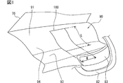
- FIG. 1 is a conceptual diagram illustrating an example of an embodiment of a vehicle display device.
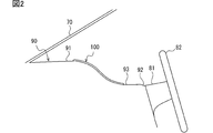
- FIG. 2 is a conceptual diagram for explaining a cross-sectional shape and a mounting position of the vehicle display device
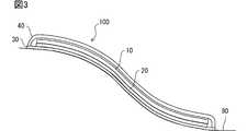
- FIG. 3 is a diagram for explaining the structure of the vehicle display device.
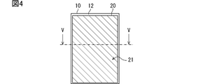
- FIG. 4 is a diagram for explaining a manner of attaching the magnet sheet to the display main body.
- FIG. 5 is a diagram showing a cross-sectional shape of the magnet sheet;
- FIG. 6 is a diagram for explaining the shape of the back plate.
- FIG. 7 is a diagram for explaining the shape of the back plate.
- FIG. 8 is a diagram showing a modification of the cross-sectional shape of the magnet sheet.
- FIG. 9 is a diagram illustrating a modification of the cross-sectional shape of the magnet sheet.
- FIG. 10 is a diagram illustrating a modification of the cross-sectional shape of the magnet sheet.
- FIG. 11A is a diagram illustrating a modification of the cross-sectional shape of the magnet sheet.
- FIG. 11B is a diagram showing a modification of the cross-sectional shape of the magnet sheet.
- FIG. 12A is a diagram showing a modification of the manner of attaching the magnet sheet to the display body
- FIG. 12B is a diagram showing a modification of the mode of attaching the magnet sheet to the display main body, FIG.
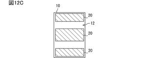
- FIG. 12C is a diagram showing a modification of the manner of attaching the magnet sheet to the display main body
- FIG. 13 is a diagram for describing a high heat generating portion and a low heat generating portion of the display main body.
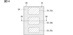
- FIG. 14 is a diagram illustrating a cross-sectional shape of a magnet sheet in a case where an adhesion rate between a sheet lower surface portion and a back plate is changed according to the position of a display main body.
- FIG. 15 is a diagram illustrating a cross-sectional shape of a magnet sheet in a case where an adhesion rate between a sheet lower surface portion and a back plate is changed according to a position of a display main body.
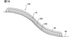
- FIG. 16 is a diagram showing a modification of the vehicle display device
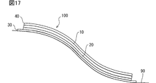
- FIG. 17 is a diagram showing a modification of the configuration of the vehicle display device.
- FIG. 18 is a diagram illustrating a modified example of the usage mode of the vehicle display device.
- the vehicular display device 100 includes a display main body 10, a magnet sheet 20, a back plate 30, and a front cover 40, which will be described later, as main components.
- the vehicle display device 100 is installed on an instrument panel (hereinafter, instrument panel 90) of the vehicle and configured to display predetermined information related to the vehicle to an occupant.
- instrument panel 90 an instrument panel
- the vehicle display device 100 is arranged so that the display surface 11 of the instrument panel 90 faces the viewing side where the face of the occupant sitting in the driver's seat is located. That is, the vehicle display device 100 is mounted on a vehicle and used so as to display information toward the viewer side.
- a plane orthogonal to the height direction of the vehicle is referred to as a vehicle horizontal plane.
- the direction from the instrument panel 90 to the seat is referred to as a seat direction.
- the seat direction includes a direction from the front end of the vehicle to the rear end and parallel to the vehicle horizontal plane (hereinafter, the rear direction of the vehicle).
- the seat direction also includes a direction that is upward at a predetermined angle (for example, about 30 degrees) with respect to the rear direction of the vehicle.
- the seat direction corresponds to the viewing side described above.
- the vehicle display device 100 of the present embodiment is arranged in an area located in front of the driver's seat in the instrument panel 90 (hereinafter, a driver's seat front area). More specifically, in the front area of the driver's seat, a continuous display is provided from the upper surface portion of the instrument panel 90 (hereinafter, instrument panel upper surface portion 91) to the vicinity of the joint portion with the steering column cover 81 (hereinafter, steering joint portion 92). It is configured to provide a surface 11.
- the instrument panel upper surface portion 91 is a surface portion connected to the lower end of the windshield 70 and substantially parallel to the vehicle horizontal plane.
- the instrument panel 90 has, as an external shape, an inclined portion 94 extending downward from the seat side end of the instrument panel upper surface portion 91 toward the vehicle lower side, and a terrace formed from the lower end of the inclined portion 94 toward the vehicle rear.
- a part 93 is provided.
- the terrace portion 93 refers to a flat portion of the entire instrument panel 90 that is formed below the instrument panel upper surface portion 91 and is substantially parallel to the vehicle horizontal plane.
- the terrace 93 corresponds to an area that continues to the steering joint 92.
- the instrument panel upper surface 91 is connected to the terrace 93 via an inclined portion 94.
- the instrument panel 90 is configured to have a gentle step from the instrument panel upper surface portion 91 to the steering joint portion 92.
- 82 indicates a steering wheel
- 83 indicates a steering pad.
- the vehicle display device 100 includes a display body 10, a magnet sheet 20, a back plate 30, and a front cover 40, as shown in FIG.
- the vehicle display device 100 includes a circuit board on which a power supply circuit, a display controller, and the like are mounted as elements not shown.
- the circuit board may also be realized using a flexible printed wiring board.
- the back plate 30 is a member located at the lowest position (in other words, the back side) in the vehicle display device 100.
- the display main body 10, the magnet sheet 20, and the front cover 40 are arranged above the back plate 30.
- the front cover 40 is a member located at the uppermost position (in other words, the viewing side) in the vehicle display device 100.
- the front cover 40 and the rear plate 30 are combined with each other using a fitting structure such as a snap fit, for example, to function as a housing for housing the display body 10.
- the display body 10 is a module that displays an image.
- the display main body 10 of the present embodiment is a display (hereinafter, a flexible display) configured so that the display surface 11 can be curved.
- a display hereinafter, a flexible display
- an organic EL display, a full active flex (registered trademark), or the like can be adopted.
- An organic EL display is a display using an organic light emitting element (OLED: Organic @ Light-Emitting @ Diode).
- Full Active Flex is a type of liquid crystal display.
- the display main body 10 is an organic EL display.
- the display main body 10 forms an information image by causing the plurality of organic light emitting elements to emit light by themselves.
- the display main body unit 10 realizes a black background by stopping light emission of the organic light emitting elements in the area where the information image is not displayed.
- the organic light emitting element is, for example, an organic light emitting diode, an organic light emitting transistor, or the like.
- the vertical direction and the horizontal direction are set in the display body 10 in advance.
- the vertical direction of the display main body 10 corresponds to the vertical direction of the display main body 10.
- the left-right direction for the display main body 10 corresponds to the horizontal direction for the display main body 10.
- a magnet sheet 20 is affixed to the back part 12 of the display body 10 (hereinafter, the display back part 12).
- the display main body 10 is attached along the back plate 30 curved by the magnetic attraction force provided by the magnet sheet 20 as described later, so that the display surface 11 is curved (that is, a curved display).
- the magnet sheet 20 is a sheet-like permanent magnet.
- the magnet sheet 20 is configured to have a desired flexibility.
- the flexibility corresponds to a concept such as flexibility, flexibility, and flexibility.
- the magnet sheet 20 is a flexible magnet.
- the magnet sheet 20 is configured as a magnet that can bend along the surface of the back plate 30 described later. Further, the magnet sheet 20 may be described as a magnet 20.
- the magnet sheet 20 is configured as a member having a thickness of about 1 mm.
- the thickness of the magnet sheet 20 can be changed as appropriate, and may be set to, for example, 1.0 mm or less, such as 0.5 mm. Further, it may be set to 2 mm or more, such as 3.0 mm.
- the sheet shape includes a configuration having a certain thickness.
- the sheet shape may include a film shape and a plate shape.
- the magnet sheet 20 is manufactured by, for example, rolling a mixture obtained by kneading a ferromagnetic powder at a predetermined ratio into an elastic base material into a sheet shape, and then performing a magnetizing process.
- a base material of the magnet sheet silicon, urethane, rubber, chlorinated polyethylene, or the like can be used.
- the base material corresponds to a binder for bonding the ferromagnetic powder.
- a ferromagnetic material refers to a magnetic material in which magnetic moments of adjacent magnetic atoms in a crystal are arranged in parallel and exhibit strong magnetism to the outside.
- Various ferromagnetic materials such as a ferrite magnet, a neodymium magnet, and an alnico magnet can be used as the ferromagnetic material constituting the magnet sheet 20.
- the content of the ferromagnetic component in the magnet sheet 20 may be set so as to provide a desired magnetic force (in other words, an attraction force) and a desired flexibility.
- the content of the ferromagnetic material component indicates a mass ratio or a volume ratio of the ferromagnetic powder to the base material. The higher the ferromagnetic component content, the higher the adsorptive power.
- the flexibility of the magnet sheet 20 can be adjusted by adjusting the type of the base material and the content ratio of the magnetic component.
- the magnet sheet 20 only needs to be magnetized so that at least the surface facing the back plate 30 (hereinafter, the sheet lower surface portion 21) functions as a permanent magnet.
- the surface of the magnet sheet 20 on the side to be bonded to the display main body 10 (hereinafter, sheet upper surface portion 22) may not be magnetized. That is, the magnet sheet 20 may be such that only the sheet lower surface portion 21 is magnetized. Of course, the magnet sheet 20 may be magnetized on both sides.
- the magnet sheet 20 of the present embodiment is configured as an anisotropic magnet in order to realize a high attraction force. In another embodiment, the magnet sheet 20 may be configured as an isotropic magnet.
- the magnet sheet 20 is adhered so as to cover the entire area of the display back surface 12. Further, as shown in FIG. 5, the seat lower surface portion 21 is formed flat (in other words, smoothly). Thereby, the sheet lower surface portion 21 is attracted to the back plate 30 described later over the entire surface. Note that the magnet sheet 20 only needs to be adhered to an area of 80% or more of the display back surface 12. The magnet sheet 20 only needs to be provided in a range that can be regarded as substantially the entire area of the display back surface 12.
- a mode in which the magnet sheet 20 is adhered in a range that can be regarded as substantially the entire region of the display back portion 12 (for example, in an area of 80% or more). Is also included.
- the back plate 30 is a metal member arranged on the back side from the display main body 10.
- the rear plate 30 corresponds to the rear housing unit 30.
- the back plate 30 is realized using a ferromagnetic material such as iron so as to be attached to the magnet sheet 20.
- the back plate 30 may be realized by using a material to which the magnet sheet 20 is adsorbed, and the material is not limited to iron. Silicon iron, ceramics (so-called ferrite) mainly containing cobalt, nickel, and iron oxide, permalloy (Fe—Ni), and the like can be used.
- the material of the back plate 30 may be a soft magnetic material or a hard magnetic material.
- the soft magnetic material refers to a ferromagnetic material whose magnetic pole disappears or reverses relatively easily.
- the hard magnetic material corresponds to a ferromagnetic material with little change in the magnetic pole.
- the mode in which a hard magnetic material is used as the material of the back plate 30 corresponds to a mode in which the back plate 30 itself is configured to function as a magnet. In the configuration in which the back plate 30 is a hard magnetic material, it is assumed that the respective contact surfaces are set to different magnetic poles so that the back plate 30 and the magnet sheet 20 are attracted.
- the back plate 30 is fixed to a predetermined position of the instrument panel 90 by snap fitting, screwing, or the like.
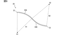
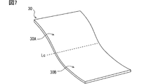
- the rear plate 30 is formed in a shape corresponding to the surface shape of a predetermined area (hereinafter, an installation area) for mounting the vehicle display device 100 on the instrument panel 90. That is, the rear plate 30 of the present embodiment is formed in a plate shape curved in the vehicle height direction as shown in FIGS. 6 and 7 so as to correspond to the curved shape of the installation area.
- the rear plate 30 has a portion that curves downward toward the rear of the vehicle (hereinafter, a first region 30A) and an opposite portion to the first region 30A. And a portion curved in the direction (hereinafter, the second region 30B).
- a line that serves as a boundary between the first region 30A and the second region 30B is referred to as an inflection curve Lc.
- the inflection curve Lc is a set of inflection points.
- the first region 30A corresponds to a region that is curved in a convex shape above the vehicle.
- the first region 30A is a region above the inflection curve Lc (that is, an upper half).
- the first region 30A corresponds to a region where the surface protrudes toward the occupant with respect to a plane connecting the upper end portion 32 and the inflection curve Lc.
- the second region 30B is a region below the inflection curve Lc (that is, a lower half).
- the second region 30B corresponds to a region where the surface sinks with respect to a plane connecting the lower end portion 33 and the inflection curve Lc.
- the second region 30B is located behind the first region 30A and corresponds to a region that is concavely curved below the vehicle.
- the first region 30A corresponds to a convex curved portion
- the second region 30B corresponds to a concave curved portion.
- the area near the middle between the upper end 32 and the lower end 33 of the back plate 30, in other words, the area near the inflection curve Lc is referred to as the center.
- the first region 30A and the second region 30B are configured by virtually dividing the back plate 30 which is an integrated object.
- the first area 30A and the second area 30B are physically (in other words, as an entity) continuously and integrally connected.
- both the first region 30A and the second region 30B are curved with a predetermined radius of curvature. That is, the first region 30A is curved at a predetermined first radius R1, and the second region 30B is curved at a predetermined second radius R2.
- O1 in the drawing represents the center of the curvature circle of the first region 30A (so-called center of curvature)
- O2 in the drawing represents the center of the curvature circle of the second region 30B.
- the first radius R1 and the second radius R2 may have the same value or different values. What is necessary is just to set the value according to the shape of the instrument panel 90. Here, as an example, it is assumed that the first radius R1 and the second radius R2 are set to 200 mm.
- the display main body 10 is attached to the viewing side surface of the back plate 30 via the magnet sheet 20 so that the upper end is located relatively forward of the vehicle and the lower end is located on the seat side. . Since the back plate 30 is made of a ferromagnetic material, the magnet sheet 20 attached to the display back portion 12 is attracted to the back plate 30. That is, the display body 10 of the present embodiment is configured to be sucked and held on the back plate 30 by the magnet sheet 20.
- the display body 10 of the present embodiment is a flexible display, and the magnet sheet 20 is also configured to have flexibility. Therefore, the display main body 10 is sucked and held (that is, adhered) to the back plate 30 in a state of being curved along the surface of the back plate 30.
- the back plate 30 is formed in a shape curved in the vehicle height direction so as to correspond to the surface shape of the instrument panel 90. Therefore, the display main body 10 is attached to the back plate 30 via the magnet sheet 20 to provide the display surface 11 that is curved (in other words, curved) in the vehicle height direction.
- the front cover 40 is a member that protects the display body 10 and the like housed in the back plate 30.
- the front cover 40 is formed into a curved shape that matches the external shape of the instrument panel 90.
- the front cover 40 is realized using a light-transmitting material such as an acrylic resin or a polycarbonate resin.
- the front cover 40 presents the display of the display main body 10 to the occupant due to its translucency.
- An antireflection film or a louver film may be provided on the display surface 11 of the display main body 10 or the surface of the front cover 40.
- the front cover 40 may have a function as an anti-reflection film or a louver film.
- the display body 10, the magnet sheet 20, and the back plate 30 can expand due to heat.
- the coefficient of linear expansion which is the rate at which the length of an object changes in response to an increase in temperature, differs depending on the material and configuration of the object. That is, the display body 10, the magnet sheet 20, and the back plate 30 have different coefficients of linear expansion.
- the linear expansion coefficient of the magnet sheet 20 is determined by the type of the base material and the content of the ferromagnetic component.
- the linear expansion coefficient between the display main body 10 and the back plate 30 includes not only a value located exactly in the middle, but also a peripheral value.
- the comparative configuration employs a sponge-based adhesive member as a means for fixing the display main body 10 to the back plate 30 inside the device (hereinafter, main body support means).
- the sponge-based adhesive member refers to a member in which an adhesive / adhesive is added to both surfaces of a band-shaped or sheet-shaped member having cushioning properties such as a sponge (hereinafter, a cushion member). .
- a cushion member a member in which an adhesive / adhesive is added to both surfaces of a band-shaped or sheet-shaped member having cushioning properties such as a sponge.
- the display main body 10 is attached to the back plate 30 by the magnetic attraction provided by the magnet sheet 20. That is, the display main body 10 of the present embodiment is not bonded to the back plate 30 by the sponge-based bonding member.
- magnets have higher thermal conductivity than members such as sponges. Therefore, according to the above configuration, the heat dissipation can be improved as compared with the comparative configuration.
- the magnet sheet 20 is attached to substantially the entire display back surface 12. According to such a configuration, the contact area between the magnet sheet 20 and the back plate 30 is larger than that in a configuration in which the magnet sheet 20 is attached to a part of the display back portion 12. Therefore, the heat radiation of the display main body 10 can be further enhanced.
- the ferromagnetic powder contained in the magnet sheet 20 has a property of absorbing electromagnetic waves. That is, the magnet sheet 20 functions as an electromagnetic wave absorbing sheet. Therefore, it is possible to reduce the possibility that the electromagnetic noise emitted from the display main body 10 reaches another electric / electronic device (hereinafter, an external device) and causes a malfunction. In addition, since the electromagnetic noise generated from the external device is also absorbed by the magnet sheet 20, the possibility that the display main body 10 malfunctions due to the electromagnetic noise generated from the external device can be reduced. That is, according to the above configuration, the level of EMC (Electro Magnetic Compatibility) measures can be increased.
- EMC Electro Magnetic Compatibility
- the display main body 10 is attached to the back plate 30 by the attraction force provided by the magnet sheet 20. According to such an attachment mode, the display main body 10 can slide with respect to the back plate 30. That is, by using magnetic attraction instead of bonding as a means for attaching the display main body 10 to the back plate 30, a certain amount of slippery permitting effect can be obtained at the joint between the members. As a result, it is possible to reduce a possibility that the display main body 10 and the rear plate 30 are damaged due to a difference in linear expansion coefficient between the display main body 10 and the rear plate 30.
- the magnet sheet 20 is formed so as to have an intermediate linear expansion coefficient between the linear expansion coefficient of the display main body 10 and the linear expansion coefficient of the back plate 30. According to such a configuration, the magnet sheet 20 acts so as to absorb the difference in thermal expansion between the display main body 10 and the back plate 30. Therefore, the possibility that the display body 10 and the back plate 30 are damaged due to the difference in the linear expansion coefficient between the display body 10 and the back plate 30 can be further reduced.
- the display main body 10 is not adhered / adhered to the back plate 30, even if the display main body 10 is damaged due to a defect in an inspection process or an external factor during use, it is relatively easy.
- the display body 10 can be replaced. In other words, the back plate 30 can be diverted.
- the contact surface of the magnet sheet 20 with the back plate 30 (that is, the sheet lower surface portion 21) is formed smoothly.
- the shape of the seat lower surface 21 is not limited to this.
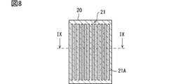
- the seat lower surface portion 21 may be provided with a plurality of linear grooves 21A. According to this configuration, the magnet sheet 20 comes into partial contact with the back plate 30, and an air flow path is formed between the magnet sheet 20 and the back plate 30. As a result, an air cooling effect can be obtained.
- the hatched portions shown in FIG. 8 represent portions that can come into contact with the back plate 30 in the sheet lower surface portion 21, and the hatched portions of the dot pattern correspond to the sheet lower surface portions 21. Represents a portion that is not in contact with the back plate 30.
- the portion of the seat lower surface 21 that is not in contact with the back plate 30 corresponds to the bottom of the groove 21A.
- FIG. 8 shows a mode in which the groove 21A is formed in the vertical direction, but as another mode, the groove 21A may extend in the horizontal direction.
- the seat lower surface portion 21 may be provided with random irregularities as shown in FIG.
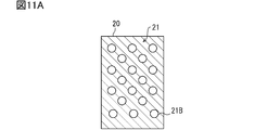
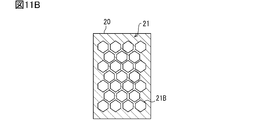
- a plurality of holes 21 ⁇ / b> B may be formed in the magnet sheet 20.
- an air layer is partially formed between the magnet sheet 20 and the back plate 30, so that an air cooling effect can be expected.
- the shape of the hole 21B may be circular as shown in FIG. 11A, or may be a regular hexagon as shown in FIG. 11B.
- the configuration in which the regular hexagonal holes 21B shown in FIG. 11B are provided without a gap corresponds to a configuration in which a honeycomb structure is introduced in a part or the entire area of the magnet sheet 20.
- the hole 21B may be realized as a concave portion instead of a through hole.
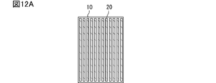
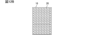
- a plurality of magnet sheets 20 may be attached to the display back surface portion 12 of the magnet sheet 20.
- an air flow path is formed between the display main body 10 and the back plate 30 as in the first modification.
- an air cooling effect can be obtained.
- the hatched portions in the diagonal lines indicate the regions on the display back surface 12 where the magnet sheet 20 is attached.
- each magnet sheet 20 does not necessarily have flexibility. You don't have to. This is because the portion of the display main body 10 where the magnet sheet 20 is not provided is bent so that the display main body 10 can be deformed along the back plate 30.
- 12A, 12B, and 12C correspond to a mode in which the magnet sheet 20 is partially adhered to the display back surface portion 12.
- 12A, 12B, and 12C correspond to a state in which a plurality of magnet sheets 20 are dispersedly arranged on the display back surface 12.
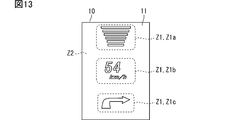
- an information presenting area Z1 for displaying an information image and a background area Z2 for not displaying an information image may be set in advance in the display body unit 10.
- the background area Z2 corresponds to an area other than the information presentation area Z1.
- Z1a shown in FIG. 13 is, for example, an information presentation area Z1 for displaying an inter-vehicle distance to a preceding vehicle.
- Z1b is, for example, an information presentation area Z1 that displays an operating state of a traveling speed, a direction indicator, and the like.
- Z1c is, for example, an information presentation area Z1 that displays a planned traveling route of the vehicle (so-called turn-by-turn).
- the organic light emitting elements located in the background area Z2 do not basically emit light.
- the organic light-emitting elements located in the information presentation area Z1 emit light at a high frequency.
- a light emitting element generates a larger amount of heat than a non-light emitting element. Therefore, the information presentation area Z1 corresponds to an area in which heat is more likely to be generated than the background area Z2.
- the information presentation area Z1 corresponds to an area having a relatively large heat generation amount (hereinafter, a high heat generation portion) in the display main body section 10, and the background area Z2 has a relatively heat generation amount in the display main body section 10.
- the information presentation area Z1 as a high heat generation part corresponds to an area where the amount of heat generation is expected to be equal to or more than a predetermined threshold.
- the background area Z2 as a low heat generation portion corresponds to an area where the amount of heat generation is expected to be less than a predetermined threshold.
- the magnet sheet 20 When the high heat generation part and the low heat generation part are mixed in the display main body 10, unevenness of the temperature distribution (and, consequently, the heat load) of the display main body 10 occurs, which may cause an unexpected operation of the display main body 10. is there. Further, if the high heat generating portion and the low heat generating portion are mixed in the display main body portion 10, the magnet sheet 20 will have a non-uniform temperature distribution (and, consequently, a heat load) corresponding thereto. If the temperature distribution of the magnet sheet 20 becomes uneven, the thermal expansion amount differs for each region, and the display body 10 may be damaged due to thermal stress.
- the magnet sheet 20 is configured such that a portion overlapping the high heat generating portion of the display main body 10 has a higher contact ratio per unit area with the back plate 30 than a portion overlapping the low heat generating portion. Is preferred.
- the portion of the magnet sheet 20 that overlaps the high heat generation portion of the display main body 10 is referred to as a high heat generation back side portion 23.
- a portion of the magnet sheet 20 that overlaps the low heat generation portion of the display main body 10 is referred to as a low heat generation back side portion 24.
- the surface of the high heat generation back side portion 23 is formed smoothly so that the adhesion ratio with the back plate 30 is equal to or more than a predetermined first target value, while the surface of the low heat generation back side portion 24 is formed with the adhesion ratio with the back plate 30.
- the first target value may be set to a relatively high value, for example, 95%.
- the second target value is set in a range lower than the first target value, for example, to a value corresponding to a ratio of the amount of heat generated between the high heat generating portion and the low heat generating portion. If the heat generation amount of the low heat generation portion is about 70% of the heat generation amount of the high heat generation portion, the second target value may be set to 70%.
- FIG. 14 illustrates the high heat generation back side portion 23 and the low heat generation back side portion 24 corresponding to the area setting of the display main body unit 10 illustrated in FIG.
- the hatched portion of the hatched pattern indicates the high heat generation back side portion 23
- the hatched portion of the dot pattern indicates the low heat generation back side portion 24.
- FIG. 15 is a diagram showing a cross-sectional shape of the magnet sheet 20 along the line XV-XV shown in FIG.
- the contact ratio with the back plate 30 is set to a different value at a location where the thermal influence of the display main body 10 is strong and at a location where the thermal influence of the display main body 10 is weak, the temperature of the magnet sheet 20 and the display main body 10 Variation in distribution can be suppressed.
- the display main body is configured so that the calorific value is different for each part, and the magnet sheet 20 is more closely connected to the back plate 30 in a region where the calorific value of the display main body 10 is higher. This corresponds to an aspect that is formed so as to be in contact.
- This modification can also be realized by applying the configuration of Modification 2. That is, the magnet sheet may be attached more densely to the high heat generation back side portion 23 than to the low heat generation back side portion 24. Even with such a configuration, it is possible to suppress variations in the temperature distribution of the magnet sheet 20 and the display main body 10. Note that this configuration corresponds to an example of a configuration in which the display main body unit 10 includes a high heat generation unit and a low heat generation unit, and the high heat generation unit is provided with magnets more densely than the low heat generation unit.
- the magnet sheet 20 is attached to the display main body 10 and the back plate 30 is realized by using a material (for example, a soft magnetic material) that sticks to the magnet. It is attached to the back plate 30.
- a material for example, a soft magnetic material
- the embodiment of the configuration in which the display main body 10 is attached to the back plate 30 by magnetic attraction is not limited to this.
- the vehicle display device 100 may be realized using a ferromagnetic sheet 20X and a magnetized back plate 30X.
- the ferromagnetic sheet 20X is a sheet-like member made of a ferromagnetic material such as a soft magnetic material.
- the ferromagnetic sheet 20X is adhered to the rear surface of the display main body 10 (that is, the display rear surface 12).
- the ferromagnetic sheet 20X is manufactured, for example, by rolling a mixture obtained by kneading a soft magnetic material powder in a predetermined ratio into an elastic base material into a sheet shape.
- the base material of the ferromagnetic sheet 20X silicon, urethane, rubber, chlorinated polyethylene, or the like can be used.
- Various soft magnetic material powders such as iron, silicon iron, cobalt, and permalloy can be used as the soft magnetic material powder.
- the ferromagnetic sheet 20X may be a sheet-shaped hard magnetic member.
- the ferromagnetic sheet 20X using a hard magnetic material is used in a state where it is not magnetized (that is, it is not magnetized) or in a state where the lower surface of the sheet is magnetized to a polarity that can be attracted to the magnetized back plate 30X. Is preferably performed.
- the magnetized back plate 30X corresponds to the back plate 30 functioning as a magnet.
- the magnetized back plate 30X is obtained by, for example, subjecting a back plate 30 made of a hard magnetic material to magnetization (that is, magnetization). Even with such a configuration, the display main body 10 is attached by the magnetic attraction provided by the back plate 30.
- the magnetized back plate 30X only needs to be magnetized on at least the surface on which the display main body 10 is disposed.
- the front cover 40 may be formed so as to be in close contact with the display surface 11 of the display body 10 as shown in FIG. In other words, the front cover 40 may be stacked on the display surface 11 of the display main body 10.
- the vehicle display device 100 may be used by being mounted so as to be buried in the instrument panel 90. In this case, it is sufficient that a recess 95 for installing the vehicle display device 100 is formed in the installation area of the instrument panel 90.
- the vehicle display device 100 is used by being attached to the instrument panel 90.
- the attachment destination of the vehicle display device 100 is not limited to the instrument panel 90. It can be installed in various places, such as the ceiling in the cabin, the back part of the front seat, and the exterior surface of the vehicle body.
- the technical idea of using a magnet as a means for attaching the display body 10 to the lower case has been applied to a display device for a vehicle.
- the technical idea can be applied to various display devices.
- the technical idea described above can be applied to a display for advertising (a display for digital signage) installed on a wall or a pillar of a commercial facility / public facility.
- the present invention can be applied to a display serving as a guide sign, a display of an automated teller machine (ATM), a mobile terminal, and the like.
- ATM automated teller machine
- the display device of the present disclosure is configured to provide a curved display surface, it is possible to use a curved structure, such as a side surface of a columnar column installed in a station yard, a public facility, or a commercial facility. Can be used by attaching to the surface.
- the back plate 30 as the lower case of the display device only needs to be formed in a shape corresponding to the surface shape of the structure to be attached.
- the display main body 10 is a flexible display, but is not limited to this.
- the display main body 10 may be configured to have a certain curved shape.
- the display main body 10 may be configured as a non-deformable display having a curved display surface.
- the display body 10 may have a flat display surface 11.
- the display main body 10 may be a combination of a flat liquid crystal panel and a backlight. In the case where the display main body 10 is provided with a backlight, the area where the backlight is provided corresponds to a high heat generating portion.
- the embodiment, the configuration, and the aspect of the display device according to an embodiment of the present disclosure have been illustrated, but the embodiment, the configuration, and the aspect according to the present disclosure are limited to the above-described embodiments, each configuration, and each aspect. Not something.
- embodiments, configurations, and aspects obtained by appropriately combining technical portions disclosed in different embodiments, configurations, and aspects are also included in the scope of the embodiments, configurations, and aspects according to the present disclosure.
Abstract
表示装置は、画像を表示するモジュールである表示本体部(10)と、表示本体部の背面側に配置されている背面側筐体部(30)と、表示本体部の背面部(12)に付着されている磁石(20)と、を備える。背面側筐体部は磁石が吸着する部材により形成される。表示本体部は、磁石が提供する磁気的吸着力によって背面側筐体部に付着されている。表示本体部が発した熱は磁石を介して背面側筐体部に伝播する。これにより、表示本体部の放熱性を高めることができる。
Description
本出願は、2018年9月27日に出願された日本国特許出願2018-182145号に基づくものであり、ここにその記載内容を参照により援用する。
本開示は、画像を表示する表示装置に関する。
画像を表示するモジュール(以降、表示本体部)として液晶ディスプレイを備える表示装置がある。また、近年では、液晶ディスプレイの代わりに、有機ELディスプレイやフルアクティブ・フレックス(登録商標)等、表示面を湾曲可能なディスプレイ(以降、フレキシブルディスプレイ)が種々登場してきている(例えば特許文献1)。このフレキシブルディスプレイ技術の発展に伴い、車両においても商品性向上の観点から、表示面が湾曲した形状を有する曲面ディスプレイを用いた車両用表示装置も提案されている。
ところで、表示装置の内部において液晶ディスプレイやフレキシブルディスプレイなどの表示本体部をロアケースに固定する手段(以降、本体支持手段)として、スポンジ系接着部材が採用されることがある(例えば特許文献2、3)。
なお、ここでのスポンジ系接着部材とは、スポンジ等のクッション性を有するテープ状又はシート状の部材の両面に接着剤/粘着剤が付加されているものを指す。ロアケースとは、表示本体部にとって背面側に位置する筐体部分を指す。
本体支持手段としてスポンジ系接着部材を用いる構成では、スポンジ部分に熱がこもりやすく、放熱性が良くない。
本開示は、表示本体部の放熱性を向上可能な表示装置を提供することを目的とする。
本開示の一態様によると、表示装置は、一例として画像を表示するモジュールである表示本体部と、表示本体部の背面側に配置されている背面側筐体部と、表示本体部の背面部に付着されている磁石と、を備える。背面側筐体部は磁石が吸着する部材により形成される。表示本体部は、磁石が提供する磁気的吸着力によって背面側筐体部に付着されている。
本開示の一態様によると、表示本体部が発した熱は磁石を介して背面側筐体部に伝播する。一般的に磁石はスポンジ等の部材よりも熱伝導性が高い。故に、表示本体部の放熱性を高めることができる。
本開示の他の一態様によると、表示装置は、画像を表示するモジュールである表示本体部と、表示本体部の背面側に配置された、強磁性体を用いてなる背面側筐体部と、を備える。表示本体部の背面部には、磁石に吸着するシート状の部材である強磁性体シートが接着されている。背面側筐体部において、表示本体部が配される方の面は、磁石として機能するように構成されている。表示本体部は、背面側筐体部が提供する磁気的吸着力によって背面側筐体部に付着されている。
本開示の他の一態様によれば、表示本体部は、背面部に接着されている強磁性体シートに、磁石としての背面側筐体部が提供する磁力が作用することによって、背面側筐体部に付着される。また、表示本体部が発した熱は強磁性体シートを介して背面側筐体部に伝播する。強磁性体シートに含まれる強磁性体は、スポンジ等の部材よりも熱伝導性が高い。故に、表示本体部の放熱性を高めることができる。
本開示についての上記および他の目的、特徴や利点は、添付図面を参照した下記詳細な説明から、より明確になる。添付図面において、
図1は、車両用表示装置の実施形態の一例を示す概念図であり、
図2は、車両用表示装置の断面形状及び取り付け位置を説明するための概念図であり、
図3は、車両用表示装置の構造を説明するための図であり、
図4は、表示本体部へのマグネットシートの付着態様を説明するための図であり、
図5は、マグネットシートの断面形状を示す図であり、
図6は、背面板の形状を説明するための図であり、
図7は、背面板の形状を説明するための図であり、
図8は、マグネットシートの断面形状の変形例を示す図であり、
図9は、マグネットシートの断面形状の変形例を示す図であり、
図10は、マグネットシートの断面形状の変形例を示す図であり、
図11Aは、マグネットシートの断面形状の変形例を示す図であり、
図11Bは、マグネットシートの断面形状の変形例を示す図であり
図12Aは、表示本体部へのマグネットシートの付着態様の変形例を示す図であり、
図12Bは、表示本体部へのマグネットシートの付着態様の変形例を示す図であり、
図12Cは、表示本体部へのマグネットシートの付着態様の変形例を示す図であり、
図13は、表示本体部が有する高発熱部、低発熱部について説明するための図であり、
図14は、表示本体部の位置に応じてシート下面部と背面板との接着率を異ならせる場合のマグネットシートの断面形状を示す図であり、
図15は、表示本体部の位置に応じてシート下面部と背面板との接着率を異ならせる場合のマグネットシートの断面形状を示す図であり、
図16は、車両用表示装置の変形例を示す図であり、
図17は、車両用表示装置の構成の変形例を示す図であり、
図18は、車両用表示装置の使用態様の変形例を示す図である。
以下、本開示の実施形態について図を用いて説明する。図1、図2は、本開示に係る車両用表示装置100の概略的な構成の一例を示す図である。車両用表示装置100は、別途後述する表示本体部10、マグネットシート20、背面板30、及びフロントカバー40を主たる構成要素として備える。車両用表示装置100は、車両のインストゥルメントパネル(以降、インパネ90)に設置されて、車両に関連する所定情報を乗員に表示する装置として構成されている。車両用表示装置100はインパネ90において表示面11が、運転席に着座した乗員の顔部が位置することとなる視認側へ向くように配置されている。つまり、車両用表示装置100は、視認側に向けて情報を表示するように車両に搭載されて使用される。
便宜上、車両の高さ方向に直交する平面のことを車両水平面と称する。また、インパネ90から座席へと向かう方向を座席方向と称する。座席方向には、車両前端から後端に向かう、車両水平面に平行な方向(以降、車両後部方向)が含まれる。また、座席方向には車両後部方向に対して所定角度(例えば30度程度)上向きとなる方向も含まれる。座席方向は前述の視認側に相当する。
本実施形態の車両用表示装置100は一例として、インパネ90において運転席の正面に位置する領域(以降、運転席正面領域)に配置されている。より具体的には、運転席正面領域のうち、インパネ90の上面部(以降、インパネ上面部91)から、ステアリングコラムカバー81との接合部(以降、ステアリング接合部92)付近まで連続的な表示面11を提供するように構成されている。インパネ上面部91は、フロントガラス70の下端と接続する、車両水平面に略平行な面部である。
インパネ90は、外観形状として、インパネ上面部91の座席側端部から車両下方に向かって延設されている傾斜部94と、当該傾斜部94の下端から車両後方に向かって形成されているテラス部93とを備えている。テラス部93は、インパネ90全体のうち、インパネ上面部91よりも下方に形成された、車両水平面に略平行な平坦部を指す。テラス部93はステアリング接合部92へと続く領域に相当する。インパネ上面部91は傾斜部94を介してテラス部93と接続している。このようにインパネ90は、インパネ上面部91からステアリング接合部92に向けてなだらかな段差を有するように構成されている。なお、82はステアリングホイールを示しており、83はステアリングパッドを示している。以下、車両用表示装置100の具体的な構成について説明する。
車両用表示装置100は、図3に示すように、表示本体部10と、マグネットシート20と、背面板30と、フロントカバー40と、を備える。なお、車両用表示装置100は、図示しない要素として、電源回路やディスプレイコントローラ等が実装された回路基板を備える。回路基板もまたフレキシブルプリント配線板を用いて実現されていれば良い。
背面板30は、車両用表示装置100において最も下方(換言すれば背面側)に位置する部材である。当該背面板30の上側に表示本体部10やマグネットシート20、フロントカバー40が配されている。フロントカバー40は、車両用表示装置100において最も上方(換言すれば視認側)に位置する部材である。フロントカバー40と背面板30は、例えばスナップフィット等の嵌合構造を用いて互いに組み合わされることにより、表示本体部10を収容する筐体として機能する。
表示本体部10は、画像を表示するモジュールである。本実施形態の表示本体部10は、表示面11を湾曲可能に構成されているディスプレイ(以降、フレキシブルディスプレイ)である。表示本体部10としては、有機ELディスプレイや、フルアクティブ・フレックス(登録商標)などを採用可能である。有機ELディスプレイは有機発光素子(OLED:Organic Light-Emitting Diode)を用いてなるディスプレイである。フルアクティブ・フレックスは液晶ディスプレイの一種である。
ここでは一例として表示本体部10は、有機ELディスプレイとする。表示本体部10は、複数の有機発光素子が自発光することによって情報画像を形成する。また、表示本体部10は情報画像を表示しない領域の有機発光素子については発光を停止させることにより、黒色の背景を実現する。有機発光素子は、例えば有機発光ダイオード、有機発光トランジスタなどである。
表示本体部10には予め上下方向と左右方向とが設定されている。表示本体部10にとっての上下方向は表示本体部10にとって縦方向に相当する。表示本体部10にとっての左右方向は表示本体部10にとっての横方向に相当する。表示本体部10の表示面11は、例えば縦方向の長さL=285mm、横方向の長さW=160mmの矩形状に形成されている。すなわち、本実施形態の表示本体部10は、アスペクト比が16:9の縦長の矩形状に形成されているフレキシブルディスプレイである。
表示本体部10において短辺に相当する2つの縁部のうち、表示本体部10にとっての上側に位置する縁部を上端部と称し、他方を下端部と称する。表示本体部10の背面部12(以降、表示背面部12)には、マグネットシート20が貼り付けられている。表示本体部10は、後述するようにマグネットシート20が提供する磁気的吸着力によって湾曲した背面板30に沿うように付着されることにより、表示面11が湾曲しているディスプレイ(つまり曲面ディスプレイ)として機能する。
マグネットシート20は、シート状の永久磁石である。マグネットシート20は、所望の屈曲性を有するように構成されている。ここでの屈曲性とは、柔軟性や、可撓性、フレキシビリティといった概念に相当する。マグネットシート20は換言すれば可撓性を有する磁石である。マグネットシート20は、後述する背面板30の表面に沿うように湾曲可能な磁石として構成されている。また、マグネットシート20は、磁石20と記載してもよい。
例えばマグネットシート20は、1ミリ程度の厚みを有する部材として構成されている。なお、マグネットシート20の厚みは、適宜変更可能であって、例えば0.5mmなど、1.0mm以下に設定されていても良い。また、3.0mmなど、2mm以上に設定されていても良い。ここでのシート状には、或る程度の厚みを有する構成も含まれる。シート状には、フィルム状や、板状も含めることができる。
当該マグネットシート20は、例えば、弾性を有するベース材料に強磁性体の粉末を所定の比率で練り込んだ混合物を、シート状に圧延加工した後に、着磁処理を施すことによって製造される。マグネットシート20のベース材料としては、シリコンや、ウレタン、ゴム、塩素化ポリエチレンなどを採用可能である。ベース材料は、強磁性粉末を接着するバインダに相当する。強磁性体は、磁性体のうち、結晶内の隣り合った磁性原子の磁気モーメントが平行に並んで外部に強い磁性を示す材料を指す。マグネットシート20を構成する強磁性体としては、フェライト磁石や、ネオジム磁石、アルニコ磁石など、多様な強磁性材料を採用可能である。
マグネットシート20における強磁性体成分の含有率は、所望の磁力(換言すれば吸着力)や所望の屈曲性を提供するように設定されれば良い。強磁性体成分の含有率は、ベース材料に対する強磁性体粉末の質量比又は体積比を指す。強磁性体成分の含有率が高いほど吸着力を高めることができる。マグネットシート20の屈曲性は、ベース材料の種類や、磁性体成分の含有比率を調整することによって調整可能である。
マグネットシート20は少なくとも背面板30と対向する面(以降、シート下面部21)が、永久磁石として機能するように着磁されていればよい。マグネットシート20において表示本体部10と貼り合わされる側の面(以降、シート上面部22)は、着磁されていなくともよい。つまり、マグネットシート20はシート下面部21のみが着磁されたものであっても良い。もちろん、マグネットシート20は両面とも着磁されていてもよい。本実施形態のマグネットシート20は、高い吸着力を実現するために異方性磁石として構成されているものとする。なお、他の態様としてマグネットシート20は等方性磁石として構成されていても良い。
マグネットシート20は、図4に示すように、表示背面部12の全領域を覆うように接着されている。また、シート下面部21は、図5に示すように、平坦に(換言すれば滑らかに)形成されている。これにより、シート下面部21は全面に渡って後述する背面板30と吸着する。なお、マグネットシート20は、表示背面部12の80%以上の領域に接着されていればよい。マグネットシート20は概ね表示背面部12の全領域とみなせる範囲に設けられていればよい。マグネットシート20が表示背面部12の全面に渡って接着されている構成には、表示背面部12の概ね全領域とみなせる範囲(例えば80%以上の領域に)マグネットシート20が接着されている態様も含まれる。
背面板30は、表示本体部10から背面側に配置されている金属部材である。背面板30は背面側筐体部30に相当する。背面板30は、マグネットシート20とひっつくように、例えば鉄などの強磁性体を用いて実現されている。背面板30は、マグネットシート20が吸着する材料を用いて実現されていればよく、その素材は鉄に限定されない。ケイ素鉄や、コバルト、ニッケル、酸化鉄を主成分とするセラミックス(いわゆるフェライト)、パーマロイ(Fe-Ni)などを採用可能である。背面板30の材料は、軟磁性体であってもよいし、硬磁性体であっても良い。軟磁性体は比較的簡単に磁極が消えたり反転してしたりする強磁性体を指す。硬磁性体は、磁極の変化が少ない強磁性体に相当する。背面板30の材料として硬磁性体を用いる態様は、背面板30そのものが磁石として作用し得るように構成されている態様に相当する。背面板30が硬磁性体である構成においては、背面板30とマグネットシート20とが吸着するように、それぞれの接触面は異なる磁極に設定されているものとする。
背面板30は、インパネ90の所定位置にスナップフィットやネジ止め等によって固定される。背面板30は、インパネ90において車両用表示装置100が取り付けられるための所定領域(以降、設置領域)の表面形状に対応する形状に形成されている。すなわち、本実施形態の背面板30は、設置領域の湾曲形状に対応するように、図6、図7に示すように、車両高さ方向に湾曲した板状に形成されている。
具体的には背面板30は、図6及び図7に示すように、車両後方に向かうにつれて車両下方へと湾曲している部分(以降、第1領域30A)と、第1領域30Aとは逆方向に湾曲している部分(以降、第2領域30B)とを備える。第1領域30Aと第2領域30Bとの境目となる線を変曲線Lcと称する。変曲線Lcは変曲点の集合である。
第1領域30Aは、車両上方に凸状に湾曲している領域に相当する。第1領域30Aは、別の観点によれば、変曲線Lcよりも上側の領域(つまり上半分)である。第1領域30Aは、上端部32と変曲線Lcとを接続する平面に対して表面が乗員側に隆起している領域に相当する。また、第2領域30Bは、変曲線Lcよりも下側の領域(つまり下半分)である。第2領域30Bは下端部33と変曲線Lcとを接続する平面に対して表面が沈み込んでいる領域に相当する。別の観点によれば、第2領域30Bは、第1領域30Aよりも車両後方に位置し、且つ、車両下方に凹状に湾曲している領域に相当する。第1領域30Aが凸状湾曲部に相当し、第2領域30Bが凹状湾曲部に相当する。背面板30において上端部32と下端部33の中間付近の領域、換言すれば、変曲線Lc付近の領域を中央部と称する。
第1領域30Aと第2領域30Bは、一体物である背面板30を仮想的に分割してなる構成である。第1領域30Aと第2領域30Bは、物理的には(換言すれば実体としては)これらは一体的に連続的につながっている。ここでは説明の簡易化のため、第1領域30A及び第2領域30Bは何れも所定の曲率半径で湾曲しているものとする。すなわち、第1領域30Aは所定の第1半径R1で湾曲しており、第2領域30Bは所定の第2半径R2で湾曲している。図中のO1は第1領域30Aの曲率円の中心(いわゆる曲率中心)を表しており、図中のO2は第2領域30Bの曲率円の中心を表している。第1半径R1と第2半径R2は同じ値であってもよいし、異なる値であってもよい。インパネ90の形状に応じた値に設定されていれば良い。ここでは一例として第1半径R1及び第2半径R2は200mmに設定されているものとする。
表示本体部10は、その上端部が相対的に車両前方に位置し、かつ、下端部が座席側に位置するように、マグネットシート20を介して背面板30の視認側表面に取り付けられている。背面板30が強磁性体で実現されているため、表示背面部12に付着されているマグネットシート20は、背面板30に吸着する。つまり、本実施形態の表示本体部10はマグネットシート20によって背面板30に吸着保持されるように構成されている。なお、本実施形態の表示本体部10はフレキシブルディスプレイであるとともに、マグネットシート20もまた屈曲性を有するように構成されている。故に、表示本体部10は背面板30の表面に沿って湾曲した状態で、背面板30に吸着保持(つまり付着)される。
また、背面板30は、上述の通り、インパネ90の表面形状に対応するように、車両高さ方向に湾曲した形状に形成されている。故に、表示本体部10はマグネットシート20を介して背面板30に取り付けられることにより、車両高さ方向に湾曲した(換言すれば曲面状の)表示面11を提供する。
フロントカバー40は、背面板30に収容されている表示本体部10等を保護する部材である。フロントカバー40はインパネ90の外観形状に適合した曲面形状に形成されている。フロントカバー40は、例えばアクリル樹脂又はポリカーボネート樹脂等、透光性を有する材料を用いて実現されている。フロントカバー40は、その透光性により、表示本体部10の表示を乗員に提示する。表示本体部10の表示面11や、フロントカバー40の表面には、反射防止フィルムやルーバーフィルムが付与されていても良い。フロントカバー40は、反射防止フィルムやルーバーフィルムとしての機能を備えるものであっても良い。
ところで、表示本体部10、マグネットシート20、及び背面板30は、熱によって膨張しうる。物体が温度の上昇に対応して長さが変化する割合である線膨張率は、物体の材質や構成に応じて異なる。つまり、表示本体部10、マグネットシート20、及び背面板30はそれぞれ異なる線膨張率を有する。
マグネットシート20の線膨張率は、ベース材料の種類や強磁性体成分の含有率によって定まる。マグネットシート20は、表示本体部10と背面板30の中間的な線膨張率を有するように構成されている。例えば、表示本体部10の線膨張率をα1、マグネットシート20の線膨張率をα2、背面板30の線膨張率をα3とすると、α2=(α1+α3)/2に設定されている。仮に表示本体部10の線膨張率α1=6×10^-6(=6×10-6)[/℃]であり、背面板30の線膨張率α3=12×10^-6(=12×10-6)[/℃]である場合には、マグネットシート20は、線膨張率α2=9×10^-6(=9×10-6)[/℃]となるように構成されていれば良い。なお、上記例においては、マグネットシート20は、8×10^-6(=8×10-6)[/℃]から10×10^-6(=10×10-6)[/℃]までの線膨張率α2を備えるように構成されていれば良い。表示本体部10と背面板30の中間的な線膨張率には、ちょうど中間に位置する値だけでなく、その周辺値も含まれる。
<実施形態の効果>
ここでは、比較構成を導入して上述した実施形態の効果について説明する。比較構成は、装置内部において表示本体部10を背面板30に固定する手段(以降、本体支持手段)として、スポンジ系接着部材が採用したものである。ここでのスポンジ系接着部材とは、帯状又はシート状に形成された、スポンジ等のクッション性を有する部材(以降、クッション部材)の両面に、接着剤/粘着剤が付加されているものを指す。比較構成では、クッション部材に熱がこもりやすい。
ここでは、比較構成を導入して上述した実施形態の効果について説明する。比較構成は、装置内部において表示本体部10を背面板30に固定する手段(以降、本体支持手段)として、スポンジ系接着部材が採用したものである。ここでのスポンジ系接着部材とは、帯状又はシート状に形成された、スポンジ等のクッション性を有する部材(以降、クッション部材)の両面に、接着剤/粘着剤が付加されているものを指す。比較構成では、クッション部材に熱がこもりやすい。
対して、上記の構成では、マグネットシート20が提供する磁気的吸着力によって表示本体部10が背面板30に付着される。すなわち、本実施形態の表示本体部10はスポンジ系接着部材によって背面板30に接着されるわけではない。また、一般的に、磁石はスポンジ等の部材よりも熱伝導性が高い。そのため、上記の構成によれば比較構成よりも放熱性を向上させることができる。
特に、本実施形態の車両用表示装置100においては、表示背面部12の略全面に渡って当該マグネットシート20が貼り付けられている。このような構成によれば、表示背面部12の一部にマグネットシート20を付着した構成に比べて、マグネットシート20と背面板30との接触面積が大きい。そのため、表示本体部10の放熱性をより一層高めることができる。
また、マグネットシート20が含有する強磁性体粉末は電磁波を吸収する性質を有する。つまり、マグネットシート20は、電磁波吸収シートとして機能する。そのため、表示本体部10から発せられた電磁性のノイズが、他の電気・電子機器(以降、外部機器)に到達し、誤作動を招く恐れを低減することができる。また、外部機器から発せられた電磁性のノイズもまたマグネットシート20によって吸収されるため、外部機器から発せられた電磁気ノイズによって表示本体部10が誤作動する恐れを低減できる。つまり、上記構成によれば、EMC(Electro Magnetic Compatibility)対策レベルを高めることができる。
ところで、一般的に、熱膨張率の異なる材料を組み合わせて使う場合には、それぞれの熱膨張率(例えば線膨張率)の違いから熱応力が生じる。この熱応力によって部材にクラックなどが入って壊れる恐れがあり、様々なものの故障原因のひとつとなりうる。比較構成では、表示本体部10が背面板30に対して接着されているため、部材同士の熱膨張率(例えば線膨張率)の違いに由来する熱応力によって、表示本体部10や背面板30が損傷する恐れがある。特に、車室内は温度変化が激しいため、その傾向は顕著となりうる。
本実施形態の構成では、表示本体部10はマグネットシート20が提供する吸着力によって背面板30に付着されている。このような付着態様によれば、表示本体部10が背面板30に対して滑ることができる。つまり、表示本体部10を背面板30に付着する手段として、接着でなく、磁気的な吸着力を用いることで、部材間の結合部分に一定量の滑り許容効果が得られる。その結果、表示本体部10と背面板30の線膨張率の違いに由来して表示本体部10や背面板30が損傷する恐れを低減することができる。
また、本実施形態では、マグネットシート20が、表示本体部10の線膨張率と背面板30の線膨張率の中間的な線膨張率を有するように形成されている。このような構成によれば、マグネットシート20が、表示本体部10と背面板30との熱膨張の差を吸収するように作用する。そのため、より一層、表示本体部10と背面板30の線膨張率の違いに由来して表示本体部10や背面板30が損傷する恐れを低減することができる。
加えて、比較構成では、スポンジ系接着部材を背面板30に貼り付ける際に、接着面と背面板30との間に気泡が入らないように、例えば真空引きや加圧ロールを用いた押圧工程などの脱泡作業が必要となる。これに対して本実施形態では、比較構成を製造する際に必要となる脱泡作業が不要となる。その結果、製造設備の簡素化や、組み付け作業の簡易化といった効果が期待できる。また、加圧ロールを用いた押圧工程を省略できるため、表示本体部10の耐久性低下や損傷のリスクも抑制できる。
その他、表示本体部10は背面板30に対して接着/粘着されていないため、検査工程での不良や使用中の外的要因で表示本体部10が損傷した場合にも、相対的に簡易に表示本体部10を交換することができる。換言すれば、背面板30は流用することもできる。
以上、本開示の実施形態を説明したが、本開示は上述の実施形態に限定されるものではなく、以降で述べる種々の変形例も本開示の技術的範囲に含まれ、さらに、下記以外にも要旨を逸脱しない範囲内で種々変更して実施することができる。例えば下記の種々の変形例は、技術的な矛盾が生じない範囲において適宜組み合わせて実施することができる。
なお、前述の実施形態で述べた部材と同一の機能を有する部材については、同一の符号を付し、その説明を省略する。また、構成の一部のみに言及している場合、他の部分については先に説明した実施形態の構成を適用することができる。
[変形例1]
上述した実施形態では、マグネットシート20における背面板30との接触面(つまりシート下面部21)が滑らかに形成されている。しかし、シート下面部21の形状はこれに限定されない。シート下面部21には、図8、図9に示すように、直線状の溝部21Aが複数設けられていても良い。当該構成によれば、マグネットシート20は背面板30と部分的に接触する事となり、マグネットシート20と背面板30との間に空気の流路が形成される。その結果、空冷効果を得ることができる。なお、図8に示す斜線パターンのハッチングを施している部分は、シート下面部21において背面板30と接触しうる部分を表しており、ドットパターンのハッチングを施している部分は、シート下面部21において背面板30と非接触な部分を表している。シート下面部21において背面板30と非接触な部分とは、溝部21Aの底部に相当する。
上述した実施形態では、マグネットシート20における背面板30との接触面(つまりシート下面部21)が滑らかに形成されている。しかし、シート下面部21の形状はこれに限定されない。シート下面部21には、図8、図9に示すように、直線状の溝部21Aが複数設けられていても良い。当該構成によれば、マグネットシート20は背面板30と部分的に接触する事となり、マグネットシート20と背面板30との間に空気の流路が形成される。その結果、空冷効果を得ることができる。なお、図8に示す斜線パターンのハッチングを施している部分は、シート下面部21において背面板30と接触しうる部分を表しており、ドットパターンのハッチングを施している部分は、シート下面部21において背面板30と非接触な部分を表している。シート下面部21において背面板30と非接触な部分とは、溝部21Aの底部に相当する。
なお、シート下面部21の形状は、上述した以外にも種々変更可能である。例えば図8では溝部21Aを縦方向に形成した態様を示しているが、他の態様として、溝部21Aは横方向に延設されていてもよい。シート下面部21には、図10に示すようにランダムな凹凸が設けられていても良い。図11A及び図11Bに示すようにマグネットシート20には複数の穴21Bが形成されていてもよい。
これらの態様によっても、マグネットシート20と背面板30との間に部分的に空気層が形成されるため、空冷効果が期待できる。なお、穴21Bの形状は、図11Aに示すように円形であってもよいし、図11Bに示すように正六角形状であってもよい。図11Bに示す正六角形の穴21Bを隙間なく設けた構成は、マグネットシート20の一部又は全領域にハニカム構造を導入した構成に相当する。なお、穴21Bは貫通孔ではなく、凹部として実現されていても良い。
[変形例2]
なお、マグネットシート20は、例えば図12A、図12B、図12Cに示すように、表示背面部12は、複数のマグネットシート20が貼り付けられていても良い。図12A、図12B、図12Cに示す構成によっても、前述の変形例1と同様に、表示本体部10と背面板30との間に空気の流路が形成される。その結果、空冷効果を得ることができる。図12A、図12B、図12Cにおいて斜線パターンのハッチングを施している部分は、表示背面部12においてマグネットシート20が貼付けられている領域を示している。
なお、マグネットシート20は、例えば図12A、図12B、図12Cに示すように、表示背面部12は、複数のマグネットシート20が貼り付けられていても良い。図12A、図12B、図12Cに示す構成によっても、前述の変形例1と同様に、表示本体部10と背面板30との間に空気の流路が形成される。その結果、空冷効果を得ることができる。図12A、図12B、図12Cにおいて斜線パターンのハッチングを施している部分は、表示背面部12においてマグネットシート20が貼付けられている領域を示している。
なお、図12Bや図12Cに示すように、湾曲方向(ここでは上下方向)に直交するように、線/帯状のマグネットシート20を複数配列した構成においては、必ずしも各マグネットシート20は柔軟性を有している必要はない。表示本体部10においてマグネットシート20が設けられていない部分が屈折することにより、表示本体部10は背面板30に沿うように変形可能であるためである。図12A、図12B、図12Cに示すマグネットシート20の付着態様は、表示背面部12に部分的にマグネットシート20を接着する態様に相当する。また、図12A、図12B、図12Cに示すマグネットシート20の付着態様は、複数のマグネットシート20を表示背面部12に分散配置した態様に相当する。
なお、車両用表示装置100の製造の簡易さといった観点においては、表示背面部12に複数のマグネットシート20を貼り付ける必要がある本変形例2よりも、1枚のマグネットシート20を貼り付ければよい実施形態や変形例1のほうが好適である。
[変形例3]
表示本体部10には、図13に示すように、情報画像を表示する情報提示領域Z1と、情報画像を表示しない背景領域Z2が、予め設定されていてもよい。背景領域Z2は、情報提示領域Z1以外の領域に相当する。図13に示すZ1aは、例えば、先行車両との車間距離を表示する情報提示領域Z1である。Z1bは、例えば、走行速度や方向指示器等の作動状態を表示する情報提示領域Z1である。Z1cは、例えば、車両の走行予定経路(いわゆるターンバイターン)を表示する情報提示領域Z1である。
表示本体部10には、図13に示すように、情報画像を表示する情報提示領域Z1と、情報画像を表示しない背景領域Z2が、予め設定されていてもよい。背景領域Z2は、情報提示領域Z1以外の領域に相当する。図13に示すZ1aは、例えば、先行車両との車間距離を表示する情報提示領域Z1である。Z1bは、例えば、走行速度や方向指示器等の作動状態を表示する情報提示領域Z1である。Z1cは、例えば、車両の走行予定経路(いわゆるターンバイターン)を表示する情報提示領域Z1である。
表示本体部10が上述した有機ELディスプレイである場合、背景領域Z2に位置する有機発光素子は基本的には発光しない。他方、情報提示領域Z1に位置する有機発光素子は発光する頻度が高い。当然、発光している素子は、発光していない素子に比べて発する熱量は大きい。故に、情報提示領域Z1は、背景領域Z2よりも発熱しやすい領域に相当する。換言すれば、情報提示領域Z1は、表示本体部10において相対的に発熱量が大きい領域(以降、高発熱部)に相当し、背景領域Z2は、表示本体部10において相対的に発熱量が小さい領域(以降、低発熱部)に相当する。高発熱部としての情報提示領域Z1は、発熱量が所定の閾値以上となることが見込まれる領域に相当する。低発熱部としての背景領域Z2は、発熱量が所定の閾値未満となることが見込まれる領域に相当する。
そして、表示本体部10に、高発熱部と低発熱部とが混在すると、表示本体部10の温度分布(ひいては熱負荷)のムラが生じ、表示本体部10に予期せぬ動作を引き起こす恐れがある。また、表示本体部10に、高発熱部と低発熱部とが混在すると、これに対応するように、マグネットシート20にも温度分布(ひいては熱負荷)のムラが生じる。マグネットシート20に温度分布のムラが生じると、領域ごとに熱膨張量が異なってしまい、表示本体部10に対して熱応力に由来する損傷を与える恐れがある。
このため、マグネットシート20において表示本体部10の高発熱部と重なる部分は、低発熱部と重なる部分よりも、背面板30との単位面積あたりの接触率が高くなるように構成されていることが好ましい。便宜上、マグネットシート20において表示本体部10の高発熱部と重なる部分を高発熱裏側部23と称する。また、マグネットシート20において表示本体部10の低発熱部と重なる部分を低発熱裏側部24と称する。
例えば高発熱裏側部23の表面は背面板30との接着率が所定の第1目標値以上となるように滑らかに形成される一方、低発熱裏側部24の表面は背面板30との接着率が所定の第2目標値となるように溝部21Aや穴21Bが形成されている。第1目標値は、例えば95%など、相対的に高い値に設定されれば良い。第2目標値は、第1目標値よりも低い範囲において、例えば高発熱部と低発熱部の発熱量の比に応じた値に設定されている。仮に低発熱部の発熱量が高発熱部の発熱量の70%程度である場合には、第2目標値は70%に設定されれば良い。図14は、図13に示す表示本体部10の領域設定に対応する高発熱裏側部23と低発熱裏側部24を示したものである。図14において、斜線パターンのハッチングを施している部分が高発熱裏側部23を示しており、ドットパターンのハッチングを示している部分が低発熱裏側部24を示している。図15は、図14に示すXV-XV線でのマグネットシート20の断面形状を示す図である。
このようにマグネットシート20において表示本体部10の熱影響が強い個所と弱い個所とで背面板30との接触率を異なる値に設定する構成によれば、マグネットシート20及び表示本体部10の温度分布のばらつきを抑制することができる。本変形例としての構成は、表示本体部が、部位毎に発熱量が異なるように構成されているとともに、マグネットシート20が、表示本体部10の発熱量が高い領域ほど密に背面板30と接触するように形成されている態様に相当する。
なお、本変形例は、変形例2としての構成を適用して実現することもできる。すなわち、高発熱裏側部23には、低発熱裏側部24よりも密にマグネットシートを貼り付けられていてもよい。そのような構成によっても、マグネットシート20及び表示本体部10の温度分布のばらつきを抑制することができる。なお、当該構成は、表示本体部10が高発熱部と低発熱部とを備えるとともに、高発熱部には、低発熱部よりも密に磁石が設けられている構成の一例に相当する。
[変形例4]
上述した実施形態では表示本体部10にマグネットシート20を貼り付けるとともに、背面板30を磁石とひっつく材料(例えば軟磁性体)を用いて実現することにより、磁気的吸着力によって表示本体部10を背面板30に付着させる。しかしながら、磁気的吸着力によって表示本体部10を背面板30に付着させる構成の実施態様はこれに限らない。
上述した実施形態では表示本体部10にマグネットシート20を貼り付けるとともに、背面板30を磁石とひっつく材料(例えば軟磁性体)を用いて実現することにより、磁気的吸着力によって表示本体部10を背面板30に付着させる。しかしながら、磁気的吸着力によって表示本体部10を背面板30に付着させる構成の実施態様はこれに限らない。
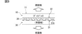
例えば図16に示すように、車両用表示装置100は、強磁性体シート20Xと、磁化背面板30Xとを用いて実現されていてもよい。強磁性体シート20Xは、例えば軟磁性体などの強磁性体を用いて成るシート状の部材である。強磁性体シート20Xは、表示本体部10の背面部(つまり表示背面部12)に接着されている。強磁性体シート20Xは、例えば、弾性を有するベース材料に軟磁性体の粉末を所定の比率で練り込んだ混合物を、シート状に圧延加工することによって製造される。強磁性体シート20Xのベース材料としては、シリコンや、ウレタン、ゴム、塩素化ポリエチレンなどを採用可能である。軟磁性体粉末としては、鉄やケイ素鉄、コバルト、パーマロイなど、多様な軟磁性材料の粉末を採用可能である。なお、強磁性体シート20Xは、シート状の硬磁性体部材であっても良い。硬磁性体を用いてなる強磁性体シート20Xは着磁処理されていない(つまり磁化されていない)状態、又は、シート下面部が磁化背面板30Xと吸着可能な極性に磁化された状態で使用されることが好ましい。
磁化背面板30Xは、磁石として機能する背面板30に相当する。磁化背面板30Xは、例えば、硬磁性体を材料とする背面板30に対して着磁(つまり磁化)処理を施したものである。このような構成によっても、表示本体部10は背面板30が提供する磁気的吸着力によって付着される。尚、磁化背面板30Xは、少なくとも表示本体部10が配置される方の面が着磁処理されていればよい。
[変形例5]
フロントカバー40は、図17に示すように、表示本体部10の表示面11に密着するように形成されていても良い。換言すれば、フロントカバー40は、表示本体部10の表示面11の上に積層されていても良い。その他、車両用表示装置100は図18に示すようにインパネ90に埋没するように取り付けられて使用されるものであっても良い。その場合、インパネ90の設置領域には、車両用表示装置100を設置するための凹部95が形成されていれば良い。
フロントカバー40は、図17に示すように、表示本体部10の表示面11に密着するように形成されていても良い。換言すれば、フロントカバー40は、表示本体部10の表示面11の上に積層されていても良い。その他、車両用表示装置100は図18に示すようにインパネ90に埋没するように取り付けられて使用されるものであっても良い。その場合、インパネ90の設置領域には、車両用表示装置100を設置するための凹部95が形成されていれば良い。
[変形例6]
上述した実施形態では、車両用表示装置100がインパネ90に取り付けられて使用されたが、車両用表示装置100の取り付け先はインパネ90に限定されない。車室内の天井や、前部座席用シートの背面部分、車両ボディの外装面など、多様な場所に設置可能である。
上述した実施形態では、車両用表示装置100がインパネ90に取り付けられて使用されたが、車両用表示装置100の取り付け先はインパネ90に限定されない。車室内の天井や、前部座席用シートの背面部分、車両ボディの外装面など、多様な場所に設置可能である。
[変形例7]
以上では、表示本体部10のロアケースへの付着手段(換言すれば装置内部における表示本体部10の支持手段)として磁石を使用するといった技術的思想を、車両用の表示装置に適用した。しかしながら、当該技術的思想は、多様な表示装置に適用することができる。例えば上記の技術的思想は、商業施設/公共施設の壁面や柱に設置される、広告用のディスプレイ(いわゆるデジタルサイネージ用のディスプレイ)に適用可能である。また、案内看板としての役割を担うディスプレイや、現金自動預け払い機(ATM:Automated/Automatic Teller Machine)のディスプレイ、携帯端末などにも適用することができる。
以上では、表示本体部10のロアケースへの付着手段(換言すれば装置内部における表示本体部10の支持手段)として磁石を使用するといった技術的思想を、車両用の表示装置に適用した。しかしながら、当該技術的思想は、多様な表示装置に適用することができる。例えば上記の技術的思想は、商業施設/公共施設の壁面や柱に設置される、広告用のディスプレイ(いわゆるデジタルサイネージ用のディスプレイ)に適用可能である。また、案内看板としての役割を担うディスプレイや、現金自動預け払い機(ATM:Automated/Automatic Teller Machine)のディスプレイ、携帯端末などにも適用することができる。
本開示の表示装置は曲面状の表示面を提供するように構成されているため、駅構内や公共施設、商業施設に設置されている円柱状の柱の側面など、湾曲している構造物の表面に取り付けて使用することができる。表示装置のロアケースとしての背面板30は、取り付け先とする構造物の表面形状に応じた形状に形成されていればよい。
[変形例8]
以上では表示本体部10をフレキシブルディスプレイとしたがこれに限定されない。表示本体部10は、一定の湾曲形状を有するように、構成されていても良い。例えば表示本体部10の基板材料として硬質な樹脂を採用することにより、表示本体部10は曲面状の表示面を有する、変形不可能なディスプレイとして構成されていても良い。また、表示本体部10は、平坦な表示面11を備えるものであっても良い。表示本体部10は、平板状の液晶パネルとバックライトとが組み合わったものでもよい。なお、表示本体部10がバックライトを備える構成の場合、バックライトが配されている領域が高発熱部に相当する。
以上では表示本体部10をフレキシブルディスプレイとしたがこれに限定されない。表示本体部10は、一定の湾曲形状を有するように、構成されていても良い。例えば表示本体部10の基板材料として硬質な樹脂を採用することにより、表示本体部10は曲面状の表示面を有する、変形不可能なディスプレイとして構成されていても良い。また、表示本体部10は、平坦な表示面11を備えるものであっても良い。表示本体部10は、平板状の液晶パネルとバックライトとが組み合わったものでもよい。なお、表示本体部10がバックライトを備える構成の場合、バックライトが配されている領域が高発熱部に相当する。
以上、本開示の一態様に係る表示装置の実施形態、構成、態様を例示したが、本開示に係る実施形態、構成、態様は、上述した各実施形態、各構成、各態様に限定されるものではない。例えば、異なる実施形態、構成、態様にそれぞれ開示された技術的部を適宜組み合わせて得られる実施形態、構成、態様についても本開示に係る実施形態、構成、態様の範囲に含まれる。
Claims (12)
- 画像を表示するモジュールである表示本体部(10)と、
前記表示本体部の背面側に配置されている背面側筐体部(30)と、
前記表示本体部の背面部(12)に付着されている磁石(20)と、を備え、
前記背面側筐体部は前記磁石が吸着する部材により形成されており、
前記表示本体部は、前記磁石が提供する磁気的吸着力によって前記背面側筐体部に付着されている表示装置。 - 請求項1に記載の表示装置であって、
前記背面側筐体部は、所定の湾曲形状に形成されており、
前記表示本体部は、前記背面側筐体部の表面に沿うように湾曲可能なディスプレイであって、
前記表示本体部は、前記背面部に配されている前記磁石によって、前記背面側筐体部の表面に沿うように付着されている表示装置。 - 請求項2に記載の表示装置であって、
前記表示装置は、車両用表示装置として構成され、
前記背面側筐体部は、インストゥルメントパネルの所定領域の外観形状に沿うように湾曲した曲面状に形成されている表示装置。 - 請求項1に記載の表示装置であって、
前記表示本体部は、曲面状の表示面を有するディスプレイであって、
前記背面側筐体部は、前記表示本体部の形状に対応する曲面状に形成されている表示装置。 - 請求項4に記載の表示装置であって、
前記表示装置は、車両用表示装置として構成され、
前記表示本体部は、インストゥルメントパネルの所定領域の外観形状に沿うように湾曲した曲面状に形成されている表示装置。 - 請求項2から5の何れか1項に記載の表示装置であって、
前記磁石は、屈曲性を有するマグネットシートであって、
前記背面部には、前記磁石としての前記マグネットシートが全面に渡って接着されている表示装置。 - 請求項6に記載の表示装置であって、
前記磁石としての前記マグネットシートにおいて、前記背面部と接着されていない方の面であるシート下面部は、全面に渡って前記背面側筐体部と接触するように平坦に形成されている表示装置。 - 請求項6に記載の表示装置であって、
前記磁石としての前記マグネットシートにおいて、前記背面部と接着されていない方の面であるシート下面部には凹凸が形成されている表示装置。 - 請求項3又は5に記載の表示装置であって、
前記磁石は、屈曲性を有するマグネットシートであって、
当前記背面部には、前記磁石としての前記マグネットシートが全面に渡って接着されており、
前記表示本体部は、部位毎に発熱量が異なるように構成されており、
前記磁石は、前記表示本体部の発熱量が高い領域ほど密に前記背面側筐体部と接触するように形成されている表示装置。 - 請求項3又は5に記載の表示装置であって、
前記表示本体部は、発熱量が所定の閾値以上となることが見込まれる領域である高発熱部(Z1)と、発熱量が所定の閾値未満となることが見込まれる領域である低発熱部(Z2)と、を備え、
前記高発熱部には、前記低発熱部よりも密に前記磁石が設けられている表示装置。 - 請求項1から10の何れか1項に記載の表示装置であって、
前記磁石は、前記表示本体部と前記背面側筐体部の線膨張率の中間的な線膨張率を有するように構成されている表示装置。 - 画像を表示するモジュールである表示本体部(10)と、
前記表示本体部の背面側に配置された、強磁性体を用いてなる背面側筐体部(30X)と、を備え、
前記表示本体部の背面部(12)には、磁石に吸着するシート状の部材である強磁性体シート(20X)が接着されており、
前記背面側筐体部において、前記表示本体部が配される方の面は、前記磁石として機能するように構成されており、
前記表示本体部は、前記背面側筐体部が提供する磁気的吸着力によって前記背面側筐体部に付着されている表示装置。
Applications Claiming Priority (2)
| Application Number | Priority Date | Filing Date | Title |
|---|---|---|---|
| JP2018182145A JP6828727B2 (ja) | 2018-09-27 | 2018-09-27 | 表示装置 |
| JP2018-182145 | 2018-09-27 |
Publications (1)
| Publication Number | Publication Date |
|---|---|
| WO2020066271A1 true WO2020066271A1 (ja) | 2020-04-02 |
Family
ID=69949326
Family Applications (1)
| Application Number | Title | Priority Date | Filing Date |
|---|---|---|---|
| PCT/JP2019/029638 WO2020066271A1 (ja) | 2018-09-27 | 2019-07-29 | 表示装置 |
Country Status (2)
| Country | Link |
|---|---|
| JP (1) | JP6828727B2 (ja) |
| WO (1) | WO2020066271A1 (ja) |
Families Citing this family (1)
| Publication number | Priority date | Publication date | Assignee | Title |
|---|---|---|---|---|
| KR20220017176A (ko) * | 2020-08-04 | 2022-02-11 | 엘지이노텍 주식회사 | 탄성 부재 및 이를 포함하는 디스플레이 장치 |
Citations (3)
| Publication number | Priority date | Publication date | Assignee | Title |
|---|---|---|---|---|
| JP2013134808A (ja) * | 2011-12-23 | 2013-07-08 | Semiconductor Energy Lab Co Ltd | 発光装置およびその作製方法 |
| JP2017227863A (ja) * | 2016-06-20 | 2017-12-28 | エルジー ディスプレイ カンパニー リミテッド | ローラブル表示装置 |
| US20180164852A1 (en) * | 2015-02-06 | 2018-06-14 | Lg Electronics Inc. | Mobile terminal |
Family Cites Families (1)
| Publication number | Priority date | Publication date | Assignee | Title |
|---|---|---|---|---|
| JPH07326017A (ja) * | 1994-06-02 | 1995-12-12 | Matsushita Electric Ind Co Ltd | 磁気ヘッド並びにその製造方法及びそれを用いた磁気記録再生装置 |
-
2018
- 2018-09-27 JP JP2018182145A patent/JP6828727B2/ja active Active
-
2019
- 2019-07-29 WO PCT/JP2019/029638 patent/WO2020066271A1/ja active Application Filing
Patent Citations (3)
| Publication number | Priority date | Publication date | Assignee | Title |
|---|---|---|---|---|
| JP2013134808A (ja) * | 2011-12-23 | 2013-07-08 | Semiconductor Energy Lab Co Ltd | 発光装置およびその作製方法 |
| US20180164852A1 (en) * | 2015-02-06 | 2018-06-14 | Lg Electronics Inc. | Mobile terminal |
| JP2017227863A (ja) * | 2016-06-20 | 2017-12-28 | エルジー ディスプレイ カンパニー リミテッド | ローラブル表示装置 |
Also Published As
| Publication number | Publication date |
|---|---|
| JP6828727B2 (ja) | 2021-02-10 |
| JP2020052265A (ja) | 2020-04-02 |
Similar Documents
| Publication | Publication Date | Title |
|---|---|---|
| KR102520539B1 (ko) | 표시장치 | |
| TWI722211B (zh) | 面板振動型聲音產生顯示裝置 | |
| CN107454519B (zh) | 通过振动面板发声的显示装置 | |
| CN113596688B (zh) | 显示设备和声音产生器 | |
| TWI300668B (en) | Organic electroluminescence display panel, display module for mobile using display panel, and electronic apparatus | |
| KR102424048B1 (ko) | 디스플레이 장치 | |
| CN109729480B (zh) | 显示设备 | |
| CN108989957B (zh) | 显示设备 | |
| US9202398B2 (en) | Display module of display device | |
| US11381672B2 (en) | Display apparatus | |
| US11064274B2 (en) | Display apparatus | |
| WO2020066271A1 (ja) | 表示装置 | |
| US20200205288A1 (en) | Display device and electronic apparatus | |
| KR20070013571A (ko) | 플라즈마 디스플레이 장치 | |
| CN112188371B (zh) | 显示设备 | |
| CN215181323U (zh) | 光学模组、电子设备 | |
| WO2023032607A1 (ja) | 表示装置 | |
| US20240080624A1 (en) | Vibration apparatus and apparatus including the same | |
| JP3777127B2 (ja) | ホワイトボード | |
| KR102312265B1 (ko) | 디스플레이 장치 | |
| JP2016119205A (ja) | 表示装置 | |
| JP2022177713A (ja) | 表示装置、および表示装置の製造方法 | |
| JP2020131756A (ja) | 車両用表示装置 | |
| JP2023003233A (ja) | 表示装置 | |
| JP2011053502A (ja) | 表示装置 |
Legal Events
| Date | Code | Title | Description |
|---|---|---|---|
| 121 | Ep: the epo has been informed by wipo that ep was designated in this application |
Ref document number: 19866870 Country of ref document: EP Kind code of ref document: A1 |
|
| NENP | Non-entry into the national phase |
Ref country code: DE |
|
| 122 | Ep: pct application non-entry in european phase |
Ref document number: 19866870 Country of ref document: EP Kind code of ref document: A1 |