WO2020066271A1 - 表示装置 - Google Patents
表示装置 Download PDFInfo
- Publication number
- WO2020066271A1 WO2020066271A1 PCT/JP2019/029638 JP2019029638W WO2020066271A1 WO 2020066271 A1 WO2020066271 A1 WO 2020066271A1 JP 2019029638 W JP2019029638 W JP 2019029638W WO 2020066271 A1 WO2020066271 A1 WO 2020066271A1
- Authority
- WO
- WIPO (PCT)
- Prior art keywords
- display
- magnet
- display device
- main body
- sheet
- Prior art date
- Legal status (The legal status is an assumption and is not a legal conclusion. Google has not performed a legal analysis and makes no representation as to the accuracy of the status listed.)
- Ceased
Links
Images


Classifications
-
- B—PERFORMING OPERATIONS; TRANSPORTING
- B60—VEHICLES IN GENERAL
- B60K—ARRANGEMENT OR MOUNTING OF PROPULSION UNITS OR OF TRANSMISSIONS IN VEHICLES; ARRANGEMENT OR MOUNTING OF PLURAL DIVERSE PRIME-MOVERS IN VEHICLES; AUXILIARY DRIVES FOR VEHICLES; INSTRUMENTATION OR DASHBOARDS FOR VEHICLES; ARRANGEMENTS IN CONNECTION WITH COOLING, AIR INTAKE, GAS EXHAUST OR FUEL SUPPLY OF PROPULSION UNITS IN VEHICLES
- B60K35/00—Instruments specially adapted for vehicles; Arrangement of instruments in or on vehicles
- B60K35/20—Output arrangements, i.e. from vehicle to user, associated with vehicle functions or specially adapted therefor
- B60K35/21—Output arrangements, i.e. from vehicle to user, associated with vehicle functions or specially adapted therefor using visual output, e.g. blinking lights or matrix displays
- B60K35/22—Display screens
-
- B—PERFORMING OPERATIONS; TRANSPORTING
- B60—VEHICLES IN GENERAL
- B60K—ARRANGEMENT OR MOUNTING OF PROPULSION UNITS OR OF TRANSMISSIONS IN VEHICLES; ARRANGEMENT OR MOUNTING OF PLURAL DIVERSE PRIME-MOVERS IN VEHICLES; AUXILIARY DRIVES FOR VEHICLES; INSTRUMENTATION OR DASHBOARDS FOR VEHICLES; ARRANGEMENTS IN CONNECTION WITH COOLING, AIR INTAKE, GAS EXHAUST OR FUEL SUPPLY OF PROPULSION UNITS IN VEHICLES
- B60K35/00—Instruments specially adapted for vehicles; Arrangement of instruments in or on vehicles
- B60K35/40—Instruments specially adapted for improving the visibility thereof to the user, e.g. fogging prevention or anti-reflection arrangements
- B60K35/425—Anti-reflection arrangements
-
- B—PERFORMING OPERATIONS; TRANSPORTING
- B60—VEHICLES IN GENERAL
- B60K—ARRANGEMENT OR MOUNTING OF PROPULSION UNITS OR OF TRANSMISSIONS IN VEHICLES; ARRANGEMENT OR MOUNTING OF PLURAL DIVERSE PRIME-MOVERS IN VEHICLES; AUXILIARY DRIVES FOR VEHICLES; INSTRUMENTATION OR DASHBOARDS FOR VEHICLES; ARRANGEMENTS IN CONNECTION WITH COOLING, AIR INTAKE, GAS EXHAUST OR FUEL SUPPLY OF PROPULSION UNITS IN VEHICLES
- B60K35/00—Instruments specially adapted for vehicles; Arrangement of instruments in or on vehicles
- B60K35/50—Instruments characterised by their means of attachment to or integration in the vehicle
-
- B—PERFORMING OPERATIONS; TRANSPORTING
- B60—VEHICLES IN GENERAL
- B60R—VEHICLES, VEHICLE FITTINGS, OR VEHICLE PARTS, NOT OTHERWISE PROVIDED FOR
- B60R11/00—Arrangements for holding or mounting articles, not otherwise provided for
- B60R11/02—Arrangements for holding or mounting articles, not otherwise provided for for radio sets, television sets, telephones, or the like; Arrangement of controls thereof
-
- G—PHYSICS
- G09—EDUCATION; CRYPTOGRAPHY; DISPLAY; ADVERTISING; SEALS
- G09F—DISPLAYING; ADVERTISING; SIGNS; LABELS OR NAME-PLATES; SEALS
- G09F9/00—Indicating arrangements for variable information in which the information is built-up on a support by selection or combination of individual elements
- G09F9/30—Indicating arrangements for variable information in which the information is built-up on a support by selection or combination of individual elements in which the desired character or characters are formed by combining individual elements
Definitions
- the present disclosure relates to a display device that displays an image.
- a display device having a liquid crystal display as a module for displaying an image
- a display main body various displays (hereinafter referred to as flexible displays), such as an organic EL display and a full active flex (registered trademark), capable of bending a display surface have appeared (for example, Patent Document 1).
- flexible displays such as an organic EL display and a full active flex (registered trademark)
- Patent Document 1 a display device for a vehicle using a curved display having a curved display surface has also been proposed from the viewpoint of improving the marketability of vehicles.
- a sponge-based adhesive member may be employed as a means for fixing a display body such as a liquid crystal display or a flexible display to a lower case inside a display device (hereinafter, body support means) (for example, Patent Documents 2 and 3). ).
- the sponge-based adhesive member refers to a sponge or other member having a cushioning property in the form of a tape or sheet having an adhesive / adhesive added to both surfaces.
- the lower case refers to a housing portion located on the back side of the display main body.
- the present disclosure aims to provide a display device capable of improving the heat radiation of the display main body.
- a display device includes, as an example, a display main body that is a module that displays an image, a rear housing that is disposed on a rear side of the display main body, and a rear surface of the display main body. And a magnet attached to the magnet.
- the rear housing portion is formed of a member to which the magnet is attracted.
- the display main body is attached to the rear housing by magnetic attraction provided by a magnet.
- heat generated by the display main body propagates to the rear housing via the magnet.
- magnets have higher thermal conductivity than members such as sponges. Therefore, the heat radiation of the display main body can be improved.
- the display device includes a display main body that is a module that displays an image, and a rear housing that is disposed on the rear side of the display main body and that includes a ferromagnetic material. , Is provided.
- a ferromagnetic sheet which is a sheet-like member that is attracted to a magnet, is adhered to the back of the display body.
- the surface of the rear housing on which the display main body is disposed is configured to function as a magnet.
- the display main body is attached to the rear housing by magnetic attraction provided by the rear housing.
- the display main unit is configured such that the magnetic force provided by the rear housing unit as a magnet acts on the ferromagnetic sheet adhered to the rear unit, thereby causing the rear housing to operate. Attached to body. Further, the heat generated by the display main body propagates to the rear housing through the ferromagnetic sheet.
- the ferromagnetic material included in the ferromagnetic sheet has higher thermal conductivity than a member such as a sponge. Therefore, the heat radiation of the display main body can be improved.
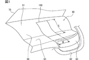
- FIG. 1 is a conceptual diagram illustrating an example of an embodiment of a vehicle display device.
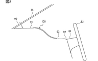
- FIG. 2 is a conceptual diagram for explaining a cross-sectional shape and a mounting position of the vehicle display device
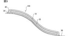
- FIG. 3 is a diagram for explaining the structure of the vehicle display device.
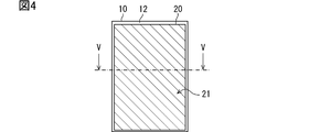
- FIG. 4 is a diagram for explaining a manner of attaching the magnet sheet to the display main body.
- FIG. 5 is a diagram showing a cross-sectional shape of the magnet sheet;
- FIG. 6 is a diagram for explaining the shape of the back plate.
- FIG. 7 is a diagram for explaining the shape of the back plate.
- FIG. 8 is a diagram showing a modification of the cross-sectional shape of the magnet sheet.
- FIG. 9 is a diagram illustrating a modification of the cross-sectional shape of the magnet sheet.
- FIG. 10 is a diagram illustrating a modification of the cross-sectional shape of the magnet sheet.
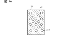
- FIG. 11A is a diagram illustrating a modification of the cross-sectional shape of the magnet sheet.
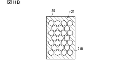
- FIG. 11B is a diagram showing a modification of the cross-sectional shape of the magnet sheet.
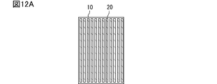
- FIG. 12A is a diagram showing a modification of the manner of attaching the magnet sheet to the display body
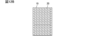
- FIG. 12B is a diagram showing a modification of the mode of attaching the magnet sheet to the display main body, FIG.
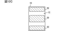
- FIG. 12C is a diagram showing a modification of the manner of attaching the magnet sheet to the display main body
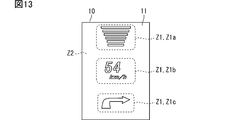
- FIG. 13 is a diagram for describing a high heat generating portion and a low heat generating portion of the display main body.
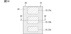
- FIG. 14 is a diagram illustrating a cross-sectional shape of a magnet sheet in a case where an adhesion rate between a sheet lower surface portion and a back plate is changed according to the position of a display main body.
- FIG. 15 is a diagram illustrating a cross-sectional shape of a magnet sheet in a case where an adhesion rate between a sheet lower surface portion and a back plate is changed according to a position of a display main body.
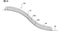
- FIG. 16 is a diagram showing a modification of the vehicle display device
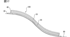
- FIG. 17 is a diagram showing a modification of the configuration of the vehicle display device.
- FIG. 18 is a diagram illustrating a modified example of the usage mode of the vehicle display device.
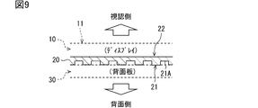
- the vehicular display device 100 includes a display main body 10, a magnet sheet 20, a back plate 30, and a front cover 40, which will be described later, as main components.
- the vehicle display device 100 is installed on an instrument panel (hereinafter, instrument panel 90) of the vehicle and configured to display predetermined information related to the vehicle to an occupant.
- instrument panel 90 an instrument panel
- the vehicle display device 100 is arranged so that the display surface 11 of the instrument panel 90 faces the viewing side where the face of the occupant sitting in the driver's seat is located. That is, the vehicle display device 100 is mounted on a vehicle and used so as to display information toward the viewer side.
- a plane orthogonal to the height direction of the vehicle is referred to as a vehicle horizontal plane.
- the direction from the instrument panel 90 to the seat is referred to as a seat direction.
- the seat direction includes a direction from the front end of the vehicle to the rear end and parallel to the vehicle horizontal plane (hereinafter, the rear direction of the vehicle).
- the seat direction also includes a direction that is upward at a predetermined angle (for example, about 30 degrees) with respect to the rear direction of the vehicle.
- the seat direction corresponds to the viewing side described above.
- the vehicle display device 100 of the present embodiment is arranged in an area located in front of the driver's seat in the instrument panel 90 (hereinafter, a driver's seat front area). More specifically, in the front area of the driver's seat, a continuous display is provided from the upper surface portion of the instrument panel 90 (hereinafter, instrument panel upper surface portion 91) to the vicinity of the joint portion with the steering column cover 81 (hereinafter, steering joint portion 92). It is configured to provide a surface 11.
- the instrument panel upper surface portion 91 is a surface portion connected to the lower end of the windshield 70 and substantially parallel to the vehicle horizontal plane.
- the instrument panel 90 has, as an external shape, an inclined portion 94 extending downward from the seat side end of the instrument panel upper surface portion 91 toward the vehicle lower side, and a terrace formed from the lower end of the inclined portion 94 toward the vehicle rear.
- a part 93 is provided.
- the terrace portion 93 refers to a flat portion of the entire instrument panel 90 that is formed below the instrument panel upper surface portion 91 and is substantially parallel to the vehicle horizontal plane.
- the terrace 93 corresponds to an area that continues to the steering joint 92.
- the instrument panel upper surface 91 is connected to the terrace 93 via an inclined portion 94.
- the instrument panel 90 is configured to have a gentle step from the instrument panel upper surface portion 91 to the steering joint portion 92.
- 82 indicates a steering wheel
- 83 indicates a steering pad.
- the vehicle display device 100 includes a display body 10, a magnet sheet 20, a back plate 30, and a front cover 40, as shown in FIG.
- the vehicle display device 100 includes a circuit board on which a power supply circuit, a display controller, and the like are mounted as elements not shown.
- the circuit board may also be realized using a flexible printed wiring board.
- the back plate 30 is a member located at the lowest position (in other words, the back side) in the vehicle display device 100.
- the display main body 10, the magnet sheet 20, and the front cover 40 are arranged above the back plate 30.
- the front cover 40 is a member located at the uppermost position (in other words, the viewing side) in the vehicle display device 100.
- the front cover 40 and the rear plate 30 are combined with each other using a fitting structure such as a snap fit, for example, to function as a housing for housing the display body 10.
- the display body 10 is a module that displays an image.
- the display main body 10 of the present embodiment is a display (hereinafter, a flexible display) configured so that the display surface 11 can be curved.
- a display hereinafter, a flexible display
- an organic EL display, a full active flex (registered trademark), or the like can be adopted.
- An organic EL display is a display using an organic light emitting element (OLED: Organic @ Light-Emitting @ Diode).
- Full Active Flex is a type of liquid crystal display.
- the display main body 10 is an organic EL display.
- the display main body 10 forms an information image by causing the plurality of organic light emitting elements to emit light by themselves.
- the display main body unit 10 realizes a black background by stopping light emission of the organic light emitting elements in the area where the information image is not displayed.
- the organic light emitting element is, for example, an organic light emitting diode, an organic light emitting transistor, or the like.
- the vertical direction and the horizontal direction are set in the display body 10 in advance.
- the vertical direction of the display main body 10 corresponds to the vertical direction of the display main body 10.
- the left-right direction for the display main body 10 corresponds to the horizontal direction for the display main body 10.
- a magnet sheet 20 is affixed to the back part 12 of the display body 10 (hereinafter, the display back part 12).
- the display main body 10 is attached along the back plate 30 curved by the magnetic attraction force provided by the magnet sheet 20 as described later, so that the display surface 11 is curved (that is, a curved display).
- the magnet sheet 20 is a sheet-like permanent magnet.
- the magnet sheet 20 is configured to have a desired flexibility.
- the flexibility corresponds to a concept such as flexibility, flexibility, and flexibility.
- the magnet sheet 20 is a flexible magnet.
- the magnet sheet 20 is configured as a magnet that can bend along the surface of the back plate 30 described later. Further, the magnet sheet 20 may be described as a magnet 20.
- the magnet sheet 20 is configured as a member having a thickness of about 1 mm.
- the thickness of the magnet sheet 20 can be changed as appropriate, and may be set to, for example, 1.0 mm or less, such as 0.5 mm. Further, it may be set to 2 mm or more, such as 3.0 mm.
- the sheet shape includes a configuration having a certain thickness.
- the sheet shape may include a film shape and a plate shape.
- the magnet sheet 20 is manufactured by, for example, rolling a mixture obtained by kneading a ferromagnetic powder at a predetermined ratio into an elastic base material into a sheet shape, and then performing a magnetizing process.
- a base material of the magnet sheet silicon, urethane, rubber, chlorinated polyethylene, or the like can be used.
- the base material corresponds to a binder for bonding the ferromagnetic powder.
- a ferromagnetic material refers to a magnetic material in which magnetic moments of adjacent magnetic atoms in a crystal are arranged in parallel and exhibit strong magnetism to the outside.
- Various ferromagnetic materials such as a ferrite magnet, a neodymium magnet, and an alnico magnet can be used as the ferromagnetic material constituting the magnet sheet 20.
- the content of the ferromagnetic component in the magnet sheet 20 may be set so as to provide a desired magnetic force (in other words, an attraction force) and a desired flexibility.
- the content of the ferromagnetic material component indicates a mass ratio or a volume ratio of the ferromagnetic powder to the base material. The higher the ferromagnetic component content, the higher the adsorptive power.
- the flexibility of the magnet sheet 20 can be adjusted by adjusting the type of the base material and the content ratio of the magnetic component.
- the magnet sheet 20 only needs to be magnetized so that at least the surface facing the back plate 30 (hereinafter, the sheet lower surface portion 21) functions as a permanent magnet.
- the surface of the magnet sheet 20 on the side to be bonded to the display main body 10 (hereinafter, sheet upper surface portion 22) may not be magnetized. That is, the magnet sheet 20 may be such that only the sheet lower surface portion 21 is magnetized. Of course, the magnet sheet 20 may be magnetized on both sides.
- the magnet sheet 20 of the present embodiment is configured as an anisotropic magnet in order to realize a high attraction force. In another embodiment, the magnet sheet 20 may be configured as an isotropic magnet.
- the magnet sheet 20 is adhered so as to cover the entire area of the display back surface 12. Further, as shown in FIG. 5, the seat lower surface portion 21 is formed flat (in other words, smoothly). Thereby, the sheet lower surface portion 21 is attracted to the back plate 30 described later over the entire surface. Note that the magnet sheet 20 only needs to be adhered to an area of 80% or more of the display back surface 12. The magnet sheet 20 only needs to be provided in a range that can be regarded as substantially the entire area of the display back surface 12.
- a mode in which the magnet sheet 20 is adhered in a range that can be regarded as substantially the entire region of the display back portion 12 (for example, in an area of 80% or more). Is also included.
- the back plate 30 is a metal member arranged on the back side from the display main body 10.
- the rear plate 30 corresponds to the rear housing unit 30.
- the back plate 30 is realized using a ferromagnetic material such as iron so as to be attached to the magnet sheet 20.
- the back plate 30 may be realized by using a material to which the magnet sheet 20 is adsorbed, and the material is not limited to iron. Silicon iron, ceramics (so-called ferrite) mainly containing cobalt, nickel, and iron oxide, permalloy (Fe—Ni), and the like can be used.
- the material of the back plate 30 may be a soft magnetic material or a hard magnetic material.
- the soft magnetic material refers to a ferromagnetic material whose magnetic pole disappears or reverses relatively easily.
- the hard magnetic material corresponds to a ferromagnetic material with little change in the magnetic pole.
- the mode in which a hard magnetic material is used as the material of the back plate 30 corresponds to a mode in which the back plate 30 itself is configured to function as a magnet. In the configuration in which the back plate 30 is a hard magnetic material, it is assumed that the respective contact surfaces are set to different magnetic poles so that the back plate 30 and the magnet sheet 20 are attracted.
- the back plate 30 is fixed to a predetermined position of the instrument panel 90 by snap fitting, screwing, or the like.
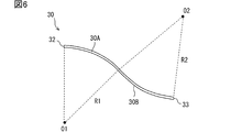
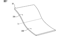
- the rear plate 30 is formed in a shape corresponding to the surface shape of a predetermined area (hereinafter, an installation area) for mounting the vehicle display device 100 on the instrument panel 90. That is, the rear plate 30 of the present embodiment is formed in a plate shape curved in the vehicle height direction as shown in FIGS. 6 and 7 so as to correspond to the curved shape of the installation area.
- the rear plate 30 has a portion that curves downward toward the rear of the vehicle (hereinafter, a first region 30A) and an opposite portion to the first region 30A. And a portion curved in the direction (hereinafter, the second region 30B).
- a line that serves as a boundary between the first region 30A and the second region 30B is referred to as an inflection curve Lc.
- the inflection curve Lc is a set of inflection points.
- the first region 30A corresponds to a region that is curved in a convex shape above the vehicle.
- the first region 30A is a region above the inflection curve Lc (that is, an upper half).
- the first region 30A corresponds to a region where the surface protrudes toward the occupant with respect to a plane connecting the upper end portion 32 and the inflection curve Lc.
- the second region 30B is a region below the inflection curve Lc (that is, a lower half).
- the second region 30B corresponds to a region where the surface sinks with respect to a plane connecting the lower end portion 33 and the inflection curve Lc.
- the second region 30B is located behind the first region 30A and corresponds to a region that is concavely curved below the vehicle.
- the first region 30A corresponds to a convex curved portion
- the second region 30B corresponds to a concave curved portion.
- the area near the middle between the upper end 32 and the lower end 33 of the back plate 30, in other words, the area near the inflection curve Lc is referred to as the center.
- the first region 30A and the second region 30B are configured by virtually dividing the back plate 30 which is an integrated object.
- the first area 30A and the second area 30B are physically (in other words, as an entity) continuously and integrally connected.
- both the first region 30A and the second region 30B are curved with a predetermined radius of curvature. That is, the first region 30A is curved at a predetermined first radius R1, and the second region 30B is curved at a predetermined second radius R2.
- O1 in the drawing represents the center of the curvature circle of the first region 30A (so-called center of curvature)
- O2 in the drawing represents the center of the curvature circle of the second region 30B.
- the first radius R1 and the second radius R2 may have the same value or different values. What is necessary is just to set the value according to the shape of the instrument panel 90. Here, as an example, it is assumed that the first radius R1 and the second radius R2 are set to 200 mm.
- the display main body 10 is attached to the viewing side surface of the back plate 30 via the magnet sheet 20 so that the upper end is located relatively forward of the vehicle and the lower end is located on the seat side. . Since the back plate 30 is made of a ferromagnetic material, the magnet sheet 20 attached to the display back portion 12 is attracted to the back plate 30. That is, the display body 10 of the present embodiment is configured to be sucked and held on the back plate 30 by the magnet sheet 20.
- the display body 10 of the present embodiment is a flexible display, and the magnet sheet 20 is also configured to have flexibility. Therefore, the display main body 10 is sucked and held (that is, adhered) to the back plate 30 in a state of being curved along the surface of the back plate 30.
- the back plate 30 is formed in a shape curved in the vehicle height direction so as to correspond to the surface shape of the instrument panel 90. Therefore, the display main body 10 is attached to the back plate 30 via the magnet sheet 20 to provide the display surface 11 that is curved (in other words, curved) in the vehicle height direction.
- the front cover 40 is a member that protects the display body 10 and the like housed in the back plate 30.
- the front cover 40 is formed into a curved shape that matches the external shape of the instrument panel 90.
- the front cover 40 is realized using a light-transmitting material such as an acrylic resin or a polycarbonate resin.
- the front cover 40 presents the display of the display main body 10 to the occupant due to its translucency.
- An antireflection film or a louver film may be provided on the display surface 11 of the display main body 10 or the surface of the front cover 40.
- the front cover 40 may have a function as an anti-reflection film or a louver film.
- the display body 10, the magnet sheet 20, and the back plate 30 can expand due to heat.
- the coefficient of linear expansion which is the rate at which the length of an object changes in response to an increase in temperature, differs depending on the material and configuration of the object. That is, the display body 10, the magnet sheet 20, and the back plate 30 have different coefficients of linear expansion.
- the linear expansion coefficient of the magnet sheet 20 is determined by the type of the base material and the content of the ferromagnetic component.
- the linear expansion coefficient between the display main body 10 and the back plate 30 includes not only a value located exactly in the middle, but also a peripheral value.
- the comparative configuration employs a sponge-based adhesive member as a means for fixing the display main body 10 to the back plate 30 inside the device (hereinafter, main body support means).
- the sponge-based adhesive member refers to a member in which an adhesive / adhesive is added to both surfaces of a band-shaped or sheet-shaped member having cushioning properties such as a sponge (hereinafter, a cushion member). .
- a cushion member a member in which an adhesive / adhesive is added to both surfaces of a band-shaped or sheet-shaped member having cushioning properties such as a sponge.
- the display main body 10 is attached to the back plate 30 by the magnetic attraction provided by the magnet sheet 20. That is, the display main body 10 of the present embodiment is not bonded to the back plate 30 by the sponge-based bonding member.
- magnets have higher thermal conductivity than members such as sponges. Therefore, according to the above configuration, the heat dissipation can be improved as compared with the comparative configuration.
- the magnet sheet 20 is attached to substantially the entire display back surface 12. According to such a configuration, the contact area between the magnet sheet 20 and the back plate 30 is larger than that in a configuration in which the magnet sheet 20 is attached to a part of the display back portion 12. Therefore, the heat radiation of the display main body 10 can be further enhanced.
- the ferromagnetic powder contained in the magnet sheet 20 has a property of absorbing electromagnetic waves. That is, the magnet sheet 20 functions as an electromagnetic wave absorbing sheet. Therefore, it is possible to reduce the possibility that the electromagnetic noise emitted from the display main body 10 reaches another electric / electronic device (hereinafter, an external device) and causes a malfunction. In addition, since the electromagnetic noise generated from the external device is also absorbed by the magnet sheet 20, the possibility that the display main body 10 malfunctions due to the electromagnetic noise generated from the external device can be reduced. That is, according to the above configuration, the level of EMC (Electro Magnetic Compatibility) measures can be increased.
- EMC Electro Magnetic Compatibility
- the display main body 10 is attached to the back plate 30 by the attraction force provided by the magnet sheet 20. According to such an attachment mode, the display main body 10 can slide with respect to the back plate 30. That is, by using magnetic attraction instead of bonding as a means for attaching the display main body 10 to the back plate 30, a certain amount of slippery permitting effect can be obtained at the joint between the members. As a result, it is possible to reduce a possibility that the display main body 10 and the rear plate 30 are damaged due to a difference in linear expansion coefficient between the display main body 10 and the rear plate 30.
- the magnet sheet 20 is formed so as to have an intermediate linear expansion coefficient between the linear expansion coefficient of the display main body 10 and the linear expansion coefficient of the back plate 30. According to such a configuration, the magnet sheet 20 acts so as to absorb the difference in thermal expansion between the display main body 10 and the back plate 30. Therefore, the possibility that the display body 10 and the back plate 30 are damaged due to the difference in the linear expansion coefficient between the display body 10 and the back plate 30 can be further reduced.
- the display main body 10 is not adhered / adhered to the back plate 30, even if the display main body 10 is damaged due to a defect in an inspection process or an external factor during use, it is relatively easy.
- the display body 10 can be replaced. In other words, the back plate 30 can be diverted.
- the contact surface of the magnet sheet 20 with the back plate 30 (that is, the sheet lower surface portion 21) is formed smoothly.
- the shape of the seat lower surface 21 is not limited to this.
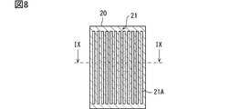
- the seat lower surface portion 21 may be provided with a plurality of linear grooves 21A. According to this configuration, the magnet sheet 20 comes into partial contact with the back plate 30, and an air flow path is formed between the magnet sheet 20 and the back plate 30. As a result, an air cooling effect can be obtained.
- the hatched portions shown in FIG. 8 represent portions that can come into contact with the back plate 30 in the sheet lower surface portion 21, and the hatched portions of the dot pattern correspond to the sheet lower surface portions 21. Represents a portion that is not in contact with the back plate 30.
- the portion of the seat lower surface 21 that is not in contact with the back plate 30 corresponds to the bottom of the groove 21A.
- FIG. 8 shows a mode in which the groove 21A is formed in the vertical direction, but as another mode, the groove 21A may extend in the horizontal direction.
- the seat lower surface portion 21 may be provided with random irregularities as shown in FIG.
- a plurality of holes 21 ⁇ / b> B may be formed in the magnet sheet 20.
- an air layer is partially formed between the magnet sheet 20 and the back plate 30, so that an air cooling effect can be expected.
- the shape of the hole 21B may be circular as shown in FIG. 11A, or may be a regular hexagon as shown in FIG. 11B.
- the configuration in which the regular hexagonal holes 21B shown in FIG. 11B are provided without a gap corresponds to a configuration in which a honeycomb structure is introduced in a part or the entire area of the magnet sheet 20.
- the hole 21B may be realized as a concave portion instead of a through hole.
- a plurality of magnet sheets 20 may be attached to the display back surface portion 12 of the magnet sheet 20.
- an air flow path is formed between the display main body 10 and the back plate 30 as in the first modification.
- an air cooling effect can be obtained.
- the hatched portions in the diagonal lines indicate the regions on the display back surface 12 where the magnet sheet 20 is attached.
- each magnet sheet 20 does not necessarily have flexibility. You don't have to. This is because the portion of the display main body 10 where the magnet sheet 20 is not provided is bent so that the display main body 10 can be deformed along the back plate 30.
- 12A, 12B, and 12C correspond to a mode in which the magnet sheet 20 is partially adhered to the display back surface portion 12.
- 12A, 12B, and 12C correspond to a state in which a plurality of magnet sheets 20 are dispersedly arranged on the display back surface 12.
- an information presenting area Z1 for displaying an information image and a background area Z2 for not displaying an information image may be set in advance in the display body unit 10.
- the background area Z2 corresponds to an area other than the information presentation area Z1.
- Z1a shown in FIG. 13 is, for example, an information presentation area Z1 for displaying an inter-vehicle distance to a preceding vehicle.
- Z1b is, for example, an information presentation area Z1 that displays an operating state of a traveling speed, a direction indicator, and the like.
- Z1c is, for example, an information presentation area Z1 that displays a planned traveling route of the vehicle (so-called turn-by-turn).
- the organic light emitting elements located in the background area Z2 do not basically emit light.
- the organic light-emitting elements located in the information presentation area Z1 emit light at a high frequency.
- a light emitting element generates a larger amount of heat than a non-light emitting element. Therefore, the information presentation area Z1 corresponds to an area in which heat is more likely to be generated than the background area Z2.
- the information presentation area Z1 corresponds to an area having a relatively large heat generation amount (hereinafter, a high heat generation portion) in the display main body section 10, and the background area Z2 has a relatively heat generation amount in the display main body section 10.
- the information presentation area Z1 as a high heat generation part corresponds to an area where the amount of heat generation is expected to be equal to or more than a predetermined threshold.
- the background area Z2 as a low heat generation portion corresponds to an area where the amount of heat generation is expected to be less than a predetermined threshold.
- the magnet sheet 20 When the high heat generation part and the low heat generation part are mixed in the display main body 10, unevenness of the temperature distribution (and, consequently, the heat load) of the display main body 10 occurs, which may cause an unexpected operation of the display main body 10. is there. Further, if the high heat generating portion and the low heat generating portion are mixed in the display main body portion 10, the magnet sheet 20 will have a non-uniform temperature distribution (and, consequently, a heat load) corresponding thereto. If the temperature distribution of the magnet sheet 20 becomes uneven, the thermal expansion amount differs for each region, and the display body 10 may be damaged due to thermal stress.
- the magnet sheet 20 is configured such that a portion overlapping the high heat generating portion of the display main body 10 has a higher contact ratio per unit area with the back plate 30 than a portion overlapping the low heat generating portion. Is preferred.
- the portion of the magnet sheet 20 that overlaps the high heat generation portion of the display main body 10 is referred to as a high heat generation back side portion 23.
- a portion of the magnet sheet 20 that overlaps the low heat generation portion of the display main body 10 is referred to as a low heat generation back side portion 24.
- the surface of the high heat generation back side portion 23 is formed smoothly so that the adhesion ratio with the back plate 30 is equal to or more than a predetermined first target value, while the surface of the low heat generation back side portion 24 is formed with the adhesion ratio with the back plate 30.
- the first target value may be set to a relatively high value, for example, 95%.
- the second target value is set in a range lower than the first target value, for example, to a value corresponding to a ratio of the amount of heat generated between the high heat generating portion and the low heat generating portion. If the heat generation amount of the low heat generation portion is about 70% of the heat generation amount of the high heat generation portion, the second target value may be set to 70%.
- FIG. 14 illustrates the high heat generation back side portion 23 and the low heat generation back side portion 24 corresponding to the area setting of the display main body unit 10 illustrated in FIG.
- the hatched portion of the hatched pattern indicates the high heat generation back side portion 23
- the hatched portion of the dot pattern indicates the low heat generation back side portion 24.
- FIG. 15 is a diagram showing a cross-sectional shape of the magnet sheet 20 along the line XV-XV shown in FIG.
- the contact ratio with the back plate 30 is set to a different value at a location where the thermal influence of the display main body 10 is strong and at a location where the thermal influence of the display main body 10 is weak, the temperature of the magnet sheet 20 and the display main body 10 Variation in distribution can be suppressed.
- the display main body is configured so that the calorific value is different for each part, and the magnet sheet 20 is more closely connected to the back plate 30 in a region where the calorific value of the display main body 10 is higher. This corresponds to an aspect that is formed so as to be in contact.
- This modification can also be realized by applying the configuration of Modification 2. That is, the magnet sheet may be attached more densely to the high heat generation back side portion 23 than to the low heat generation back side portion 24. Even with such a configuration, it is possible to suppress variations in the temperature distribution of the magnet sheet 20 and the display main body 10. Note that this configuration corresponds to an example of a configuration in which the display main body unit 10 includes a high heat generation unit and a low heat generation unit, and the high heat generation unit is provided with magnets more densely than the low heat generation unit.
- the magnet sheet 20 is attached to the display main body 10 and the back plate 30 is realized by using a material (for example, a soft magnetic material) that sticks to the magnet. It is attached to the back plate 30.
- a material for example, a soft magnetic material
- the embodiment of the configuration in which the display main body 10 is attached to the back plate 30 by magnetic attraction is not limited to this.
- the vehicle display device 100 may be realized using a ferromagnetic sheet 20X and a magnetized back plate 30X.
- the ferromagnetic sheet 20X is a sheet-like member made of a ferromagnetic material such as a soft magnetic material.
- the ferromagnetic sheet 20X is adhered to the rear surface of the display main body 10 (that is, the display rear surface 12).
- the ferromagnetic sheet 20X is manufactured, for example, by rolling a mixture obtained by kneading a soft magnetic material powder in a predetermined ratio into an elastic base material into a sheet shape.
- the base material of the ferromagnetic sheet 20X silicon, urethane, rubber, chlorinated polyethylene, or the like can be used.
- Various soft magnetic material powders such as iron, silicon iron, cobalt, and permalloy can be used as the soft magnetic material powder.
- the ferromagnetic sheet 20X may be a sheet-shaped hard magnetic member.
- the ferromagnetic sheet 20X using a hard magnetic material is used in a state where it is not magnetized (that is, it is not magnetized) or in a state where the lower surface of the sheet is magnetized to a polarity that can be attracted to the magnetized back plate 30X. Is preferably performed.
- the magnetized back plate 30X corresponds to the back plate 30 functioning as a magnet.
- the magnetized back plate 30X is obtained by, for example, subjecting a back plate 30 made of a hard magnetic material to magnetization (that is, magnetization). Even with such a configuration, the display main body 10 is attached by the magnetic attraction provided by the back plate 30.
- the magnetized back plate 30X only needs to be magnetized on at least the surface on which the display main body 10 is disposed.
- the front cover 40 may be formed so as to be in close contact with the display surface 11 of the display body 10 as shown in FIG. In other words, the front cover 40 may be stacked on the display surface 11 of the display main body 10.
- the vehicle display device 100 may be used by being mounted so as to be buried in the instrument panel 90. In this case, it is sufficient that a recess 95 for installing the vehicle display device 100 is formed in the installation area of the instrument panel 90.
- the vehicle display device 100 is used by being attached to the instrument panel 90.
- the attachment destination of the vehicle display device 100 is not limited to the instrument panel 90. It can be installed in various places, such as the ceiling in the cabin, the back part of the front seat, and the exterior surface of the vehicle body.
- the technical idea of using a magnet as a means for attaching the display body 10 to the lower case has been applied to a display device for a vehicle.
- the technical idea can be applied to various display devices.
- the technical idea described above can be applied to a display for advertising (a display for digital signage) installed on a wall or a pillar of a commercial facility / public facility.
- the present invention can be applied to a display serving as a guide sign, a display of an automated teller machine (ATM), a mobile terminal, and the like.
- ATM automated teller machine
- the display device of the present disclosure is configured to provide a curved display surface, it is possible to use a curved structure, such as a side surface of a columnar column installed in a station yard, a public facility, or a commercial facility. Can be used by attaching to the surface.
- the back plate 30 as the lower case of the display device only needs to be formed in a shape corresponding to the surface shape of the structure to be attached.
- the display main body 10 is a flexible display, but is not limited to this.
- the display main body 10 may be configured to have a certain curved shape.
- the display main body 10 may be configured as a non-deformable display having a curved display surface.
- the display body 10 may have a flat display surface 11.
- the display main body 10 may be a combination of a flat liquid crystal panel and a backlight. In the case where the display main body 10 is provided with a backlight, the area where the backlight is provided corresponds to a high heat generating portion.
- the embodiment, the configuration, and the aspect of the display device according to an embodiment of the present disclosure have been illustrated, but the embodiment, the configuration, and the aspect according to the present disclosure are limited to the above-described embodiments, each configuration, and each aspect. Not something.
- embodiments, configurations, and aspects obtained by appropriately combining technical portions disclosed in different embodiments, configurations, and aspects are also included in the scope of the embodiments, configurations, and aspects according to the present disclosure.
Landscapes
- Engineering & Computer Science (AREA)
- Mechanical Engineering (AREA)
- Chemical & Material Sciences (AREA)
- Combustion & Propulsion (AREA)
- Transportation (AREA)
- Physics & Mathematics (AREA)
- General Physics & Mathematics (AREA)
- Theoretical Computer Science (AREA)
- Devices For Indicating Variable Information By Combining Individual Elements (AREA)
- Fittings On The Vehicle Exterior For Carrying Loads, And Devices For Holding Or Mounting Articles (AREA)
- Instrument Panels (AREA)
Applications Claiming Priority (2)
| Application Number | Priority Date | Filing Date | Title |
|---|---|---|---|
| JP2018182145A JP6828727B2 (ja) | 2018-09-27 | 2018-09-27 | 表示装置 |
| JP2018-182145 | 2018-09-27 |
Publications (1)
| Publication Number | Publication Date |
|---|---|
| WO2020066271A1 true WO2020066271A1 (ja) | 2020-04-02 |
Family
ID=69949326
Family Applications (1)
| Application Number | Title | Priority Date | Filing Date |
|---|---|---|---|
| PCT/JP2019/029638 Ceased WO2020066271A1 (ja) | 2018-09-27 | 2019-07-29 | 表示装置 |
Country Status (2)
| Country | Link |
|---|---|
| JP (1) | JP6828727B2 (enExample) |
| WO (1) | WO2020066271A1 (enExample) |
Families Citing this family (1)
| Publication number | Priority date | Publication date | Assignee | Title |
|---|---|---|---|---|
| KR20220017176A (ko) * | 2020-08-04 | 2022-02-11 | 엘지이노텍 주식회사 | 탄성 부재 및 이를 포함하는 디스플레이 장치 |
Citations (3)
| Publication number | Priority date | Publication date | Assignee | Title |
|---|---|---|---|---|
| JP2013134808A (ja) * | 2011-12-23 | 2013-07-08 | Semiconductor Energy Lab Co Ltd | 発光装置およびその作製方法 |
| JP2017227863A (ja) * | 2016-06-20 | 2017-12-28 | エルジー ディスプレイ カンパニー リミテッド | ローラブル表示装置 |
| US20180164852A1 (en) * | 2015-02-06 | 2018-06-14 | Lg Electronics Inc. | Mobile terminal |
Family Cites Families (1)
| Publication number | Priority date | Publication date | Assignee | Title |
|---|---|---|---|---|
| JPH07326017A (ja) * | 1994-06-02 | 1995-12-12 | Matsushita Electric Ind Co Ltd | 磁気ヘッド並びにその製造方法及びそれを用いた磁気記録再生装置 |
-
2018
- 2018-09-27 JP JP2018182145A patent/JP6828727B2/ja active Active
-
2019
- 2019-07-29 WO PCT/JP2019/029638 patent/WO2020066271A1/ja not_active Ceased
Patent Citations (3)
| Publication number | Priority date | Publication date | Assignee | Title |
|---|---|---|---|---|
| JP2013134808A (ja) * | 2011-12-23 | 2013-07-08 | Semiconductor Energy Lab Co Ltd | 発光装置およびその作製方法 |
| US20180164852A1 (en) * | 2015-02-06 | 2018-06-14 | Lg Electronics Inc. | Mobile terminal |
| JP2017227863A (ja) * | 2016-06-20 | 2017-12-28 | エルジー ディスプレイ カンパニー リミテッド | ローラブル表示装置 |
Also Published As
| Publication number | Publication date |
|---|---|
| JP2020052265A (ja) | 2020-04-02 |
| JP6828727B2 (ja) | 2021-02-10 |
Similar Documents
| Publication | Publication Date | Title |
|---|---|---|
| US11985444B2 (en) | Display apparatus | |
| CN113115187B (zh) | 显示设备 | |
| CN107454512B (zh) | 面板振动型发声显示装置 | |
| US20210112324A1 (en) | Display apparatus | |
| US20210315111A1 (en) | Display Device | |
| TWI300668B (en) | Organic electroluminescence display panel, display module for mobile using display panel, and electronic apparatus | |
| CN101083144B (zh) | 显示装置 | |
| CN107561753A (zh) | 面板振动型发声显示装置 | |
| US20140078719A1 (en) | Display module of display device | |
| CN114501240A (zh) | 显示装置和包括该显示装置的车辆 | |
| CN115171555B (zh) | 电子设备 | |
| CN103171220A (zh) | 用于移动设备的窗口和包括该窗口的移动设备 | |
| CN112289245B (zh) | 显示装置和包括该显示装置的车辆 | |
| JP6828727B2 (ja) | 表示装置 | |
| CN112188371B (zh) | 显示设备 | |
| US20200205288A1 (en) | Display device and electronic apparatus | |
| KR101706312B1 (ko) | 유기 발광 표시 장치 | |
| JP3777127B2 (ja) | ホワイトボード | |
| WO2023032607A1 (ja) | 表示装置 | |
| CN120529486A (zh) | 显示设备 | |
| KR20250087253A (ko) | 디스플레이장치 | |
| GB2625641A (en) | Apparatus for outputting a sound | |
| JP2022177713A (ja) | 表示装置、および表示装置の製造方法 | |
| JP2020131756A (ja) | 車両用表示装置 |
Legal Events
| Date | Code | Title | Description |
|---|---|---|---|
| 121 | Ep: the epo has been informed by wipo that ep was designated in this application |
Ref document number: 19866870 Country of ref document: EP Kind code of ref document: A1 |
|
| NENP | Non-entry into the national phase |
Ref country code: DE |
|
| 122 | Ep: pct application non-entry in european phase |
Ref document number: 19866870 Country of ref document: EP Kind code of ref document: A1 |