WO2020059617A1 - エアガイド構造 - Google Patents
エアガイド構造 Download PDFInfo
- Publication number
- WO2020059617A1 WO2020059617A1 PCT/JP2019/035834 JP2019035834W WO2020059617A1 WO 2020059617 A1 WO2020059617 A1 WO 2020059617A1 JP 2019035834 W JP2019035834 W JP 2019035834W WO 2020059617 A1 WO2020059617 A1 WO 2020059617A1
- Authority
- WO
- WIPO (PCT)
- Prior art keywords
- lid
- closed position
- air guide
- discharge opening
- opening
- Prior art date
- Legal status (The legal status is an assumption and is not a legal conclusion. Google has not performed a legal analysis and makes no representation as to the accuracy of the status listed.)
- Ceased
Links
Images




Classifications
-
- B—PERFORMING OPERATIONS; TRANSPORTING
- B60—VEHICLES IN GENERAL
- B60K—ARRANGEMENT OR MOUNTING OF PROPULSION UNITS OR OF TRANSMISSIONS IN VEHICLES; ARRANGEMENT OR MOUNTING OF PLURAL DIVERSE PRIME-MOVERS IN VEHICLES; AUXILIARY DRIVES FOR VEHICLES; INSTRUMENTATION OR DASHBOARDS FOR VEHICLES; ARRANGEMENTS IN CONNECTION WITH COOLING, AIR INTAKE, GAS EXHAUST OR FUEL SUPPLY OF PROPULSION UNITS IN VEHICLES
- B60K11/00—Arrangement in connection with cooling of propulsion units
- B60K11/02—Arrangement in connection with cooling of propulsion units with liquid cooling
- B60K11/04—Arrangement or mounting of radiators, radiator shutters, or radiator blinds
-
- B—PERFORMING OPERATIONS; TRANSPORTING
- B62—LAND VEHICLES FOR TRAVELLING OTHERWISE THAN ON RAILS
- B62D—MOTOR VEHICLES; TRAILERS
- B62D25/00—Superstructure or monocoque structure sub-units; Parts or details thereof not otherwise provided for
- B62D25/08—Front or rear portions
Definitions
- the present disclosure relates to an air guide structure.
- Patent Document 1 describes a cooling air introduction structure for a vehicle.
- the air-cooled heat exchanger of this vehicle includes a radiator and a condenser, the outer peripheral side of the condenser is covered with a shroud, and the rear side of the vehicle with respect to the air-cooled heat exchanger passes through the air-cooled heat exchanger.
- a fan for generating an air flow is arranged.
- the cooling air introduction structure includes an under cover that covers a space in the power unit room from below the vehicle.
- the power unit chamber is provided with a first cooling air passage having an under cover as a lower wall.
- the first cooling air passage is a passage for guiding air from the first inlet of the bumper cover, which is the front end of the power unit chamber, to the air-cooled heat exchanger via the space between the power unit and the under cover.
- the upper wall of the first cooling air passage includes an upper wall extending from the upper end edge of the first inlet of the bumper cover to the vehicle rear side, a lower surface of the power unit, and an upper wall of the shroud. It is composed of
- the cooling air introduction structure described in Patent Literature 1 includes an under cover (air guide) that covers the space in the power unit room from below the vehicle, and an air-cooled type is provided above the air guide from a first introduction port of a bumper cover.
- a cooling air passage for guiding air to the heat exchanger is provided. For this reason, if foreign matter enters the cooling air passage from the first inlet of the bumper cover, the foreign matter is deposited above the air guide, which may cause a decrease in cooling efficiency or damage to the air guide. is there.
- foreign matters such as pebbles and plants enter the cooling air passage together with water from the first inlet of the bumper cover, and the foreign matters enter above the air guide. May be deposited, which may cause a decrease in cooling efficiency and damage to the air guide.
- an object of the present disclosure is to provide an air guide structure that can suppress the accumulation of foreign matter above the air guide.
- a first aspect of the present disclosure is arranged such that an air inlet on one side in a predetermined direction that communicates between the outside and the inside of a vehicle and the other side in the predetermined direction than the air inlet.
- An air guide structure for partitioning at least a lower part of a cooling air flow path between the heat exchanger and the heat exchanger includes a plate-shaped air guide main body, a lid, and a lid opening / closing means.
- the plate-shaped air guide main body has a discharge opening vertically penetrating on one side from the heat exchanger, and is disposed below the cooling air flow path and intersects the vertical direction.
- the lid is tiltably supported on the peripheral edge of the discharge opening of the air guide main body, and is tiltable downward from a closed position for closing the discharge opening to open the discharge opening.
- the lid opening / closing means can switch the lid between a closed state in which the discharge opening is closed in the closed position and an open state in which the lid is tilted from the closed position to open the discharge opening.
- the air guide main body has a discharge opening that penetrates in the up-down direction on one side (for example, forward) of the heat exchanger in a predetermined direction (for example, front-rear direction).
- a lid that can open and close the discharge opening is supported on the peripheral edge of the discharge opening of the air guide main body in a tiltable manner.
- a lid opening / closing means capable of switching the lid between a closed state and an open state is provided. For this reason, for example, the lid opening / closing means switches between the closed state and the open state every predetermined time, or the closed state according to the weight of the sediment that has entered the cooling air flow path using a predetermined threshold value.
- the lid opening / closing means may be an electric means for tilting the lid by an actuator or the like, or a mechanical means for tilting the lid downward by the weight of the deposits deposited on the upper surface of the lid. Means may be used.
- a second aspect of the present disclosure is the air guide structure of the first aspect, wherein the lid opening / closing means has a biasing means for biasing the lid upward toward the closed position.
- the urging force of the urging means against the lid toward the closing position is a predetermined force from above with respect to the lid such that the lid switches between the closed state and the open state according to the magnitude of the load input from above.
- the lid is held in the closed position until a load of a magnitude is input, and the strength is set so that the lid cannot be held in the closed position when a load greater than the predetermined size is input from above to the lid. I have.
- the lid opening / closing means has an urging means for urging the lid toward the closed position, and the urging force of the urging means depends on the magnitude of the load input from above. Is held in the closed position until a load of a predetermined size is input from above to the lid so that the lid switches between the closed state and the open state, and the predetermined size is applied to the lid from above. If a load greater than that is input, the strength is set so that the lid cannot be held in the closed position. Therefore, for example, the lid is held in the closed position until the weight of the deposit deposited above the lid reaches the predetermined weight, and the weight of the deposit becomes equal to or more than the predetermined weight. Sometimes, the discharge opening of the air guide main body is opened, and the deposit can be discharged from the discharge opening to below the air guide main body.
- the deposit can be discharged to the lower side of the air guide main body only by appropriately setting the urging force of the urging means (for example, a spring), the accumulation of foreign matter on the upper surface of the air guide main body with a simple structure. Can be suppressed.
- the urging force of the urging means for example, a spring
- a third aspect of the present disclosure is the air guide structure according to the first aspect or the second aspect, and further includes a regulating unit.
- the restricting means restricts tilting of the lid upward from the closed position.
- a regulating means is provided for regulating the tilting of the lid upward from the closed position. For this reason, since the lid does not tilt upward from the closed position, it is possible to prevent the discharge opening from being opened due to the tilt of the lid upward from the closed position. Also, since the lid does not tilt upward from the closed position, unlike the case where the lid tilts upward from the closed position and projects into the cooling air flow path, the increase in the resistance of the cooling air flow path due to the lid is suppressed. can do.
- FIG. 1 is an external perspective view of a vehicle to which an air guide structure according to an embodiment of the present disclosure is applied.
- FIG. 2 is a sectional view taken along the line II-II of FIG.
- FIG. 3 is a schematic view of FIG. 2 viewed from the direction III.
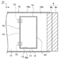
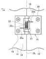
- FIG. 4 is an enlarged view of a main part of FIG.
- FIG. 5 is a schematic view of FIG. 4 viewed from the V direction.
- FIG. 6A is an explanatory view of an air guide structure according to another embodiment, and shows an air guide structure using a leaf spring.
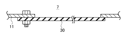
- FIG. 6B is an explanatory diagram of an air guide structure according to another embodiment, which illustrates a structure using a rubber plate.
- FR indicates the front of the vehicle
- UP indicates the upper side
- IN indicates the inner side in the vehicle width direction
- the dashed line CL indicates the rotation axis of the lid.
- the left-right direction refers to the left-right direction in a state in which the vehicle faces the front.
- the vehicle 1 to which the air guide structure according to the present embodiment is applied includes an engine behind a bumper 2 at an end of a front side (one side in a predetermined direction (front-rear direction)) of the vehicle 1.
- Room 3 is provided.
- an engine not shown
- a heat exchanger 4 in this embodiment, a radiator 4a and an intercooler 4b
- a fan 5 and the like are arranged.
- the bumper 2 is provided with an air inlet 6 for introducing air passing through the heat exchanger 4 into the engine room 3.
- the air inlet 6 of the bumper 2 communicates between the outside and the inside of the vehicle 1 (engine room 3).
- the heat exchanger 4 is disposed at a position separated from the air inlet 6 of the bumper 2 rearward (on the other side in the predetermined direction).
- the fan 5 is disposed behind the heat exchanger 4 and generates a front-to-back air flow passing through the heat exchanger 4.
- a duct (air) defining an air flow path 7 (hereinafter, referred to as a cooling air flow path 7) from the air inlet 6 to the heat exchanger 4 is provided between the air inlet 6 of the bumper 2 and the heat exchanger 4.
- Guide) 10 is provided.
- the duct 10 is a resin duct, and penetrates in the front-rear direction by a duct upper plate portion 10a, left and right duct side plate portions 10b and 10c, and a duct lower plate portion 10d. It is formed in a substantially rectangular cylindrical shape, and defines a cooling air flow path 7 therein.
- the front ends of the plates 10a to 10d are connected to the peripheral edge of the air inlet 6 of the bumper 2, and the rear ends of the plates 10a to 10d are connected to the peripheral surface of the heat exchanger 4.
- the duct upper plate portion 10a is a plate portion that crosses the vertical direction, and extends continuously from the upper edge of the air inlet 6 of the bumper 2 to the upper surface of the heat exchanger 4.
- the left and right duct side plates 10b and 10c are plate portions intersecting with the vehicle width direction, and extend continuously from the left and right side edges of the air inlet 6 of the bumper 2 to the left and right side portions of the heat exchanger 4. .
- the duct lower plate portion 10d is a plate portion that crosses in the vertical direction, and extends continuously from the lower edge of the air inlet 6 of the bumper 2 to the lower surface of the heat exchanger 4. The duct 10 guides the air introduced from the air inlet 6 of the bumper 2 to the front of the heat exchanger 4.
- the duct lower plate portion 10d includes a resin main body (air guide main body) 11 formed in a plate shape crossing in a vertical direction, a resin lid (lid) 12 supported by the main body 11, A plurality (two in this embodiment) of spring-loaded hinges (cover opening / closing means) 15 are provided.
- the main body portion 11 is a plate portion that crosses in the vertical direction, and includes a front region 11a extending substantially horizontally rearward from a lower edge portion of the air inlet 6 of the bumper 2 and a rear lower portion from a rear end of the front region 11a.
- a middle region 11b extending obliquely to the horizontal direction, and a rear region 11c extending substantially horizontally rearward from the rear end of the middle region 11b to the lower surface of the heat exchanger 4.
- a substantially rectangular foreign matter discharge opening (discharge opening) 13 penetrating in the vertical direction is formed in the rear region 11c of the main body 11 near the front of the front surface of the heat exchanger 4.
- Left and right opening side edges 17 and 18 of the main body 11 that divides the left and right of the foreign matter discharge opening 13 are arranged near the inner surfaces of the left and right duct side plates 10b and 10c.
- the lid 12 is a substantially rectangular plate slightly smaller than the foreign matter discharge opening 13.
- a front edge 16 of the lid 12 is rotatably supported via a hinge 15 with a spring on an opening front edge 14 of the main body 11 that defines the front of the foreign matter discharge opening 13.
- the lid 12 rotatably supported by the opening front edge portion 14 of the main body 11 is moved downward from a closed position (the position of the lid 12 indicated by a solid line in FIG. 2) for closing the foreign matter discharge opening 13 of the main body 11. By tilting, the foreign matter discharge opening 13 of the main body 11 can be opened.
- the lid 12 tilts downward from the closed position the rear edge of the lid 12 tilts forward and downward from near the opening rear edge 23 of the main body 11 (closed position).
- the hinge with spring 15 includes a first wing 19 fixed to the lower surface of the opening front edge 14 of the main body 11, and a lower surface of the front edge 16 of the lid 12.
- the second wing 20 is fixed to the first wing 19, a core rod 21 connecting the first wing 19 and the second wing 20, and a coil spring (biasing means) 22 through which the core rod 21 is inserted.
- the first wing 19 and the second wing 20 are rotatably connected to each other by a core rod 21 extending in the vehicle width direction.
- the axis CL of the core rod 21 (the dashed line CL in FIG. 5) is the rotation axis of the hinge 15 with spring.
- the axis CL of the core rod 21 of the hinge 15 with the spring becomes the rotation axis of the lid 12.
- the rotation of the second wing 20 in one direction with respect to the first wing 19 is performed at a position where the first wing 19 and the second wing 20 are arranged on the same plane side by side in the front-rear direction (shown in FIG. 4).
- State the first wing 19 and the second wing 20 are regulated by contact with each other.
- Such a restriction functions as a restriction means for restricting the tilt of the lid 12 in the closing direction for closing the foreign matter discharge opening 13 of the main body 11 to the closed position.
- the coil spring 22 has one end 22a and the other end 22b extending linearly, and a coil spring main body 22c between the one end 22a and the end 22b.
- the core rod 21 is inserted through the coil spring main body 22c.
- One end 22 a of the coil spring 22 contacts the lower surface of the first wing 19, and the other end 22 b of the coil spring 22 contacts the lower surface of the second wing 20.
- the coil spring 22 urges the lid 12 upward toward the closed position.
- the urging force of the coil spring 22 holds the lid 12 in the closed position until a load of a predetermined magnitude is input from above (the cooling air flow path 7 side) to the lid 12 in the closed position.
- the hinge 15 with the spring moves the lid 12 in a closed state (a state shown by a solid line in FIG. 2) in which the lid 12 is held in a closed position in accordance with the magnitude of the load input to the lid 12, and moves downward from the closed position.
- It functions as a lid opening / closing means that can be switched to an open state in which the foreign matter discharge opening 13 of the main body 11 is opened by tilting (a state shown by a two-dot chain line in FIG. 2).
- the predetermined magnitude (threshold) of the load can be obtained by an experiment, a simulation, or the like.
- the duct 10 configured as described above, for example, when a large amount of river water enters the duct 10 from the air inlet 6 of the bumper 2 when the vehicle 1 enters the river, the duct 10 enters the duct 10.
- the weight of the water acts on the lid 12 in the closed position.
- the weight of the water causes the lid 12 to tilt in the opening direction and open the foreign matter discharge opening 13. Then, water is discharged from the foreign matter discharge opening 13 to below the duct lower plate portion 10d.
- the sediment can be discharged to the lower side of the duct lower plate portion 10d only by appropriately setting the urging force of the coil spring 22 of the spring-loaded hinge 15, so that the sediment can be easily transferred to the upper surface of the duct lower plate portion 10d. Of foreign matter can be suppressed.
- the hinge 15 with spring regulates the tilt of the lid 12 in the closing direction for closing the foreign substance discharge opening 13 of the main body 11 to the closed position. For this reason, since the lid 12 does not tilt upward from the closed position, it is possible to prevent the foreign matter discharge opening 13 from being opened due to the tilt of the lid 12 above the closed position. In addition, since the lid 12 does not tilt upward from the closed position, unlike the case where the lid 12 tilts upward from the closed position and projects into the cooling air flow path 7, the cooling air flow path 7 An increase in resistance can be suppressed.
- the resin duct 10 is provided, but the duct 10 is not limited to the resin, and may be, for example, a metal duct.
- the duct (air guide) 10 having a substantially rectangular cylindrical shape penetrating in the front-rear direction is provided.
- the present invention is not limited to this, and an air guide that partitions at least the lower part of the cooling air flow path 7 is provided.
- an air guide having only the duct lower plate portion 10d in the present embodiment may be used.
- the front edge 16 of the lid 12 is rotatably connected to the opening front edge 14 of the main body 11.
- the lid 12 may be rotatably connected to one of the left and right opening side edges 17, 18 or the opening rear edge 23 of the main body 11. That is, in the present embodiment, when the lid 12 is tilted in the opening direction from the closed position, the rear end edge of the lid 12 is tilted forward and downward from near the opening rear edge 23 of the main body 11 (closed position).
- the side edge of the lid 12 on one side in the vehicle width direction may be tilted downward on the other side in the vehicle width direction, or the front edge of the lid 12 tilts rearward and downward. It may be configured.
- the foreign matter discharge opening 13 of the main body 11 is formed near the front of the front surface of the heat exchanger 4, but the position of the foreign matter discharge opening 13 is not limited to this.
- the shape of the lid 12 is slightly smaller than the foreign matter discharge opening 13, but the shape of the lid 12 is not limited to this.
- the shape of the lid 12 may be made larger than the foreign matter discharge opening 13, and the lid 12 in the closed position may be brought into contact with the peripheral edge of the foreign matter discharge opening 13 of the main body 11 from below.
- the rotation of the hinge 15 with the spring in one direction is restricted to a predetermined position, thereby functioning as a restricting means for restricting the tilt of the lid 12 in the closing direction to the closed position.
- the regulation means is not limited to this.
- the rear surface of the opening front edge portion 14 of the main body portion 11 and the front surface of the front end edge portion 16 of the lid body 12 may be configured to abut at the closed position, and the abutment may be used as a restricting means.
- a stopper 29 protruding forward from the opening rear edge 23 may be provided on the upper surface of the opening rear edge 23 of the portion 11, and the stopper 29 may function as a regulating means.
- the regulating means for regulating the tilt of the lid 12 in the closing direction to the closed position is provided, but the regulating means may not be provided.
- the urging force of the coil spring 22 is set so that the lid 12 is held at the closed position in a state where no external force other than the weight of the lid 12 is acting on the coil spring 22 of the spring-loaded hinge 15. May be. That is, the lid 12 may be held at the closed position without providing a restricting means for restricting the movement of the lid 12 above the closed position.
- the lid 12 is connected to the main body 11 via the hinge 15 with a spring.
- the present invention is not limited to this.
- the lid 12 may be connected to the main body 11 via a metal leaf spring (lid opening / closing means, biasing means) 28.
- the urging force of the leaf spring 28 applies the lid 12 to the closed position until a load of a predetermined magnitude is input from above (the cooling air flow path 7 side) to the lid 12 at the closed position.
- a load equal to or larger than the above-mentioned predetermined value is input to the lid 12 from above, the strength is set so that the lid 12 cannot be held at the closed position.
- a lid (lid, lid opening / closing means, urging means) 30 made of flat rubber may be provided instead of the lid 12.
- the elasticity of the lid 30 is determined so that the lid 30 is not deformed until the load of a predetermined magnitude is input from above (the cooling air flow path 7 side) to the lid 30 in the closed position.
- the lid 30 is elastically deformed and is set to an elastic modulus at which the closed position cannot be held.
- the lid 30 elastically deformed in the opening direction from the closed position urges the lid 30 itself toward the closed position by a restoring force.
- the mechanical lid opening / closing means (spring hinge 15) is provided in which the lid 12 tilts downward due to the weight of the deposits or the like deposited on the upper surface of the lid 12.
- the opening / closing means is not limited to a mechanical means, and may be an electric means capable of switching the lid 12 between a closed state and an open state.
- a tilting means (motor or the like) capable of tilting the lid 12 and a controller or the like capable of controlling the tilting means at predetermined time intervals to switch the lid 12 between a closed state and an open state may be provided.
- a sensor or the like capable of measuring the weight of the foreign matter deposited on the upper surface of the duct lower plate portion 10d is provided, and the weight of the foreign material (deposit) deposited on the upper surface of the duct lower plate portion 10d exceeds a predetermined weight.
- a controller or the like that can control the tilting means to switch the lid 12 from the closed state to the open state may be provided.
- the air inlet 6 is provided on the front side (one side) of the vehicle 1 in the front-rear direction (predetermined direction), and the heat exchanger 4 is provided on the rear side (other side) of the air inlet 6.
- the present invention is not limited to this, and an air inlet may be provided on one side in the vehicle width direction (predetermined direction), and a heat exchanger may be provided on the other side in the vehicle width direction of the air inlet.
- an air guide structure capable of suppressing accumulation of foreign matter above the air guide can be provided.
Landscapes
- Engineering & Computer Science (AREA)
- Chemical & Material Sciences (AREA)
- Combustion & Propulsion (AREA)
- Transportation (AREA)
- Mechanical Engineering (AREA)
- Cooling, Air Intake And Gas Exhaust, And Fuel Tank Arrangements In Propulsion Units (AREA)
- Body Structure For Vehicles (AREA)
Abstract
ダクト10のダクト下板部10dは、上下方向に交叉する板状に形成された本体部11と、本体部11に支持される蓋体12と、ばね付ヒンジ15とを備える。本体部11の後部領域11cには、上下方向に貫通する異物排出開口13が形成される。蓋体12の前端縁部は、本体部11の開口前縁部に対し、ばね付ヒンジ15を介して回転自在に支持される。蓋体12は、本体部11の異物排出開口13を閉止する閉止位置から下方へ傾動することによって、本体部11の異物排出開口13を開放可能である。ばね付ヒンジ15は、蓋体12を、蓋体12に入力する荷重の大きさに応じて、閉止位置に保持した閉止状態と、閉止位置から下方へ傾動して本体部11の異物排出開口13を開放した開放状態とに切り替える。
Description
本開示は、エアガイド構造に関する。
特許文献1には、車両の冷却風導入構造が記載されている。この車両の空冷式熱交換器は、ラジエータ及びコンデンサを含み、コンデンサの外周側はシュラウドによって覆われており、空冷式熱交換器に対して車両後方側には、空冷式熱交換器を通過する空気流を生成するファンが配置されている。冷却風導入構造は、パワーユニット室内の空間を車両下方側から覆うアンダカバーを備えている。パワーユニット室には、アンダカバーを下壁部とする第一冷却風通路が設けられている。第一冷却風通路は、パワーユニット室の前端部であるバンパカバーの第一導入口から、パワーユニットとアンダカバーとの間を経て空冷式熱交換器に空気を導くための通路である。第一冷却風通路の上壁部は、バンパカバーにおける第一導入口の上端縁部から車両後方側に延設された上壁部と、パワーユニットの下面部と、シュラウドの上壁部とを含んで構成されている。
特許文献1に記載の冷却風導入構造では、パワーユニット室内の空間を車両下方側から覆うアンダカバー(エアガイド)を備えており、エアガイドの上方には、バンパカバーの第一導入口から空冷式熱交換器に空気を導くための冷却風通路が設けられている。このため、バンパカバーの第一導入口から異物が冷却風通路に浸入してしまうと、エアガイドの上方に異物が堆積してしまい、冷却効率の低下やエアガイドの破損を招いてしまうおそれがある。例えば、車両を比較的水深の深い河川内で走行させた場合には、バンパカバーの第一導入口から水とともに小石や植物等の異物が冷却風通路に浸入して、エアガイドの上方に異物が堆積してしまう可能性があり、冷却効率の低下やエアガイドの破損を招いてしまうおそれがある。
そこで、本開示は、エアガイドの上方への異物の堆積を抑制することが可能なエアガイド構造の提供を目的とする。
上記課題を解決するため、本開示の第1の態様は、車両の外部と内部とを連通する所定方向の一側の空気導入口と前記空気導入口よりも前記所定方向の他側に配置される熱交換器との間の冷却風流路の少なくとも下方を区画するエアガイド構造であって、板状のエアガイド本体と蓋部と蓋部開閉手段とを備える。板状のエアガイド本体は、熱交換器よりも上記一側で上下方向に貫通する排出開口を有し、冷却風流路の下方に配置されて上下方向と交叉する。蓋部は、エアガイド本体の排出開口の周縁部に傾動自在に支持され、排出開口を閉止する閉止位置から下方へ傾動して排出開口を開放可能である。蓋部開閉手段は、蓋部を、閉止位置で排出開口を閉止する閉止状態と、閉止位置から傾動して排出開口を開放する開放状態とに切り替え可能である。
上記構成では、エアガイド本体は、上下方向に貫通する排出開口を熱交換器よりも所定方向(例えば、前後方向)の一側(例えば、前方)に有する。エアガイド本体の排出開口の周縁部には、排出開口を開閉可能な蓋部が傾動自在に支持されている。そして、蓋部を、閉止状態と開放状態とに切り替え可能な蓋部開閉手段が設けられている。このため、例えば、蓋部開閉手段が、所定時間ごとに閉止状態と開放状態とを切り替え、或いは、所定の閾値を用いて冷却風流路内に侵入した堆積物の重さに応じて閉止状態と開放状態とを切り替えるなどして、冷却風流路に浸入した異物をエアガイド本体の排出開口からエアガイド本体の下方へ排出することができる。従って、エアガイド本体の上面への異物の堆積を抑制することができる。なお、蓋部開閉手段は、蓋部をアクチュエータ等によって傾動させる電気的な手段であってもよいし、或いは蓋部の上面に堆積した堆積物の重さによって蓋部が下方へ傾動する機械的な手段であってもよい。
本開示の第2の態様は、上記第1の態様のエアガイド構造であって、蓋部開閉手段は、蓋部を閉止位置側へ向かって上方へ付勢する付勢手段を有する。蓋部に対する付勢手段による閉止位置側への付勢力は、上方から入力する荷重の大きさに応じて蓋部が閉止状態と開放状態とに切り替わるように、蓋部に対して上方から所定の大きさの荷重が入力するまでは蓋部を閉止位置に保持し、蓋部に対して上方から上記所定の大きさ以上の荷重が入力すると蓋部を閉止位置に保持できない強さに設定されている。
上記構成では、蓋部開閉手段は、蓋部を閉止位置側へ向かって付勢する付勢手段を有し、付勢手段の付勢力は、上方から入力する荷重の大きさに応じて蓋部が閉止状態と開放状態とに切り替わるように、蓋部に対して上方から所定の大きさの荷重が入力するまでは蓋部を閉止位置に保持し、蓋部に対して上方から上記所定の大きさ以上の荷重が入力すると蓋部を閉止位置に保持できない強さに設定されている。このため、例えば、蓋部の上方に堆積する堆積物の重さが所定の重さになるまでは蓋部を閉止位置に保持し、堆積物の重さが上記所定の重さ以上になったときにエアガイド本体の排出開口を開放して、堆積物を排出開口からエアガイド本体の下方へ排出することができる。
また、付勢手段(例えばバネ)の付勢力を適切に設定するだけで堆積物をエアガイド本体の下方へ排出することができるので、簡易な構造でエアガイド本体の上面への異物の堆積を抑制することができる。
本開示の第3の態様は、上記第1の態様または上記第2の態様のエアガイド構造であって、規制手段を備える。規制手段は、閉止位置よりも上方への蓋部の傾動を規制する。
上記構成では、閉止位置よりも上方への蓋部の傾動を規制する規制手段を備える。このため、蓋部は、閉止位置から上方へ傾動しないので、閉止位置よりも上方への蓋部の傾動による排出開口の開放を防止することができる。また、蓋部が閉止位置から上方へ傾動しないので、蓋部が閉止位置よりも上方へ傾動して冷却風流路内に突出する場合とは異なり、蓋部による冷却風流路の抵抗の増大を抑制することができる。
本開示によれば、エアガイドの上方への異物の堆積を抑制することができる。
以下、本開示の一実施形態を図面に基づいて説明する。なお、各図において、FRは車両の前方を、UPは上方を、INは車幅方向内側をそれぞれ示し、一点鎖線CLは蓋体の回転軸を示す。また、以下の説明において、左右方向は車両前方を向いた状態での左右方向を意味する。
図1及び図2に示すように、本実施形態に係るエアガイド構造を適用する車両1は、車両1の前側(所定方向(前後方向)の一側)の端部のバンパー2の後方にエンジンルーム3を有する。エンジンルーム3内には、エンジン(図示省略)、熱交換器4(本実施形態では、ラジエータ4a及びインタークーラ4b)、及びファン5等が配置される。バンパー2には、熱交換器4を通過させる空気をエンジンルーム3へ導入するための空気導入口6が形成される。バンパー2の空気導入口6は、車両1の外部と内部(エンジンルーム3)とを連通する。熱交換器4は、バンパー2の空気導入口6から後方(上記所定方向の他側)に離間した位置に配置される。ファン5は、熱交換器4の後方に配置され、熱交換器4を通過する前方から後方への空気の流れを生成する。バンパー2の空気導入口6と熱交換器4との間には、空気導入口6から熱交換器4への空気の流路7(以下、冷却風流路7という。)を区画するダクト(エアガイド)10が設けられる。
図2及び図3に示すように、ダクト10は、樹脂製のダクトであって、ダクト上板部10a、左右のダクト側板部10b,10c、及びダクト下板部10dによって、前後方向に貫通する略矩形筒状に形成され、内部に冷却風流路7を区画する。各板部10a~10dの前端部は、バンパー2の空気導入口6の周縁部に接続され、各板部10a~10dの後端部は、熱交換器4の周面部に接続される。ダクト上板部10aは、上下方向と交叉する板部であって、バンパー2の空気導入口6の上縁部から熱交換器4の上面部まで連続して延びる。左右のダクト側板部10b,10cは、車幅方向と交叉する板部であって、バンパー2の空気導入口6の左右の側縁部から熱交換器4の左右の側面部まで連続して延びる。ダクト下板部10dは、上下方向に交叉する板部であって、バンパー2の空気導入口6の下縁部から熱交換器4の下面部まで連続して延びる。ダクト10は、バンパー2の空気導入口6から導入された空気を熱交換器4の前面へ案内する。
ダクト下板部10dは、上下方向に交叉する板状に形成された樹脂製の本体部(エアガイド本体)11と、本体部11に支持される樹脂製の蓋体(蓋部)12と、複数(本実施形態では、2つ)のばね付ヒンジ(蓋部開閉手段)15とを備える。
本体部11は、上下方向に交叉する板部であって、バンパー2の空気導入口6の下縁部から略水平に後方へ延びる前部領域11aと、前部領域11aの後端から後下方へ水平方向に対して傾斜して延びる中間部領域11bと、中間部領域11bの後端から略水平に後方へ熱交換器4の下面部まで延びる後部領域11cとを有する。本体部11の後部領域11cのうち熱交換器4の前面の前方近傍には、上下方向に貫通する略矩形状の異物排出開口(排出開口)13が形成される。異物排出開口13の左右を区画する本体部11の左右の開口側縁部17,18は、左右のダクト側板部10b,10cの内面近傍に配置される。
蓋体12は、異物排出開口13よりも僅かに小さい略矩形状の板体である。蓋体12の前端縁部16は、異物排出開口13の前方を区画する本体部11の開口前縁部14に対し、ばね付ヒンジ15を介して回転自在に支持される。本体部11の開口前縁部14に回転自在に支持された蓋体12は、本体部11の異物排出開口13を閉止する閉止位置(図2に実線で示す蓋体12の位置)から下方へ傾動することによって、本体部11の異物排出開口13を開放可能である。蓋体12が閉止位置から下方へ傾動する際には、蓋体12の後端縁が、本体部11の開口後縁部23の近傍(閉止位置)から前下方へ傾動する。
図4及び図5に示すように、ばね付ヒンジ15は、本体部11の開口前縁部14の下面側に固定される第1の羽19と、蓋体12の前端縁部16の下面側に固定される第2の羽20と、第1の羽19と第2の羽20とを連結する芯棒21と、芯棒21が挿通するコイルばね(付勢手段)22とを有する。第1の羽19と第2の羽20とは、車幅方向に延びる芯棒21によって互いに回転自在に連結される。芯棒21の軸心CL(図5の一点鎖線CL)が、ばね付ヒンジ15の回転軸となる。すなわち、ばね付ヒンジ15の芯棒21の軸心CLが、蓋体12の回転軸となる。第1の羽19に対する第2の羽20の一方向への回転は、第1の羽19と第2の羽20とが前後に並んで略同一平面上に配置される位置(図4に示す状態)で、第1の羽19と第2の羽20とが互いに当接することによって規制される。係る規制は、本体部11の異物排出開口13を閉止する閉方向への蓋体12の傾動を、閉止位置までに規制する規制手段として機能する。
コイルばね22は、直線状に延びる一端部22a及び他端部22bと、一端部22aと端部22bとの間のコイルばね本体22cとを有する。コイルばね本体22cには、芯棒21が挿通する。コイルばね22の一端部22aは、第1の羽19の下面に当接し、コイルばね22の他端部22bは、第2の羽20の下面に当接する。コイルばね22は、蓋体12を閉止位置側へ向かって上方へ付勢する。コイルばね22の付勢力は、閉止位置の蓋体12に対して上方(冷却風流路7側)から所定の大きさの荷重が入力するまでは蓋体12を閉止位置に保持し、蓋体12に対して上方から上記所定の大きさ以上の荷重が入力すると蓋体12を閉止位置に保持できない強さに設定される。すなわち、ばね付ヒンジ15は、蓋体12を、蓋体12に入力する荷重の大きさに応じて、閉止位置に保持した閉止状態(図2で実線で示す状態)と、閉止位置から下方へ傾動して本体部11の異物排出開口13を開放した開放状態(図2で二点鎖線で示す状態)とに切り替え可能な蓋部開閉手段として機能する。なお、荷重の上記所定の大きさ(閾値)は、実験やシミュレーション等によって求めることができる。
上記のように構成されたダクト10では、例えば、車両1を河川に侵入させた際に、バンパー2の空気導入口6からダクト10内に河川の水が大量に浸入すると、ダクト10内に侵入した水の重さが閉止位置の蓋体12に作用する。ダクト10内に侵入した水から蓋体12に対して上方から上記所定の大きさ以上の荷重が入力すると、その水の重さによって蓋体12が開方向へ傾動して異物排出開口13を開放し、水が異物排出開口13からダクト下板部10dの下方へ排出される。
また、河川の水と共に石や枯葉等の異物がダクト10内に侵入すると、ダクト10内のダクト下板部10dの上面に異物が堆積する。ダクト下板部10dの上面に堆積した異物(堆積物)の重さが閉止位置の蓋体12に作用し、堆積物から蓋体12に対して上方から上記所定の大きさ以上の荷重が入力すると、その堆積物の重さによって蓋体12が開方向へ傾動して異物排出開口13を開放し、堆積物が異物排出開口13からダクト下板部10dの下方へ排出される。
従って、本実施形態によれば、ダクト下板部10dの上面への異物の堆積を抑制することができる。
また、ばね付ヒンジ15のコイルばね22の付勢力を適切に設定するだけで堆積物をダクト下板部10dの下方へ排出することができるので、簡易な構造でダクト下板部10dの上面への異物の堆積を抑制することができる。
また、ばね付ヒンジ15は、本体部11の異物排出開口13を閉止する閉方向への蓋体12の傾動を、閉止位置までに規制する。このため、蓋体12は、閉止位置から上方へ傾動しないので、閉止位置よりも上方への蓋体12の傾動による異物排出開口13の開放を防止することができる。また、蓋体12が閉止位置から上方へ傾動しないので、蓋体12が閉止位置よりも上方へ傾動して冷却風流路7内に突出する場合とは異なり、蓋体12による冷却風流路7の抵抗の増大を抑制することができる。
なお、本実施形態では、樹脂製のダクト10を設けたが、ダクト10は樹脂製に限定されず、例えば、金属製のダクトであってもよい。
また、本実施形態では、前後方向に貫通する略矩形筒状のダクト(エアガイド)10を設けたが、これに限定されるものではなく、冷却風流路7の少なくとも下方を区画するエアガイドであればよく、例えば、本実施形態におけるダクト下板部10dのみのエアガイドであってもよい。
また、本実施形態では、本体部11の開口前縁部14に対して蓋体12の前端縁部16を回転自在に連結したが、これに限定されるものではなく、例えば、本体部11の左右の開口側縁部17,18のいずれか一方や、或いは本体部11の開口後縁部23に対して蓋体12を回転自在に連結してもよい。すなわち、本実施形態では、蓋体12が閉止位置から開方向へ傾動する際に、蓋体12の後端縁が本体部11の開口後縁部23の近傍(閉止位置)から前下方へ傾動する構成としたが、蓋体12の車幅方向一側の側端縁が車幅方向他側の下方へ傾動する構成としてもよいし、或いは、蓋体12の前端縁が後下方へ傾動する構成としてもよい。
また、本実施形態では、本体部11の異物排出開口13を、熱交換器4の前面の前方近傍に形成したが、異物排出開口13の位置はこれに限定されるものではない。
また、本実施形態では、蓋体12の形状を、異物排出開口13よりも僅かに小さい形状としたが、蓋体12の形状はこれに限定されるものではない。例えば、蓋体12の形状を、異物排出開口13よりも大きくし、閉止位置の蓋体12を、本体部11の異物排出開口13の周縁部に下方から当接させてもよい。
また、本実施形態では、ばね付ヒンジ15の一方向への回転を所定の位置までに規制することによって、閉方向への蓋体12の傾動を閉止位置までに規制する規制手段として機能させたが、規制手段はこれに限定されるものではない。例えば、閉止位置で本体部11の開口前縁部14の後面と蓋体12の前端縁部16の前面とが当接するように構成し、係る当接を規制手段としてもよいし、或いは、本体部11の開口後縁部23の上面に開口後縁部23から前方へ突出するストッパ29(図4参照)を設け、当該ストッパ29を規制手段として機能させてもよい。
また、本実施形態では、閉方向への蓋体12の傾動を閉止位置までに規制する規制手段を設けたが、規制手段を設けなくてもよい。例えば、ばね付ヒンジ15のコイルばね22に対して蓋体12の重さ以外の外力が作用していない状態で、蓋体12が閉止位置に保持されるようにコイルばね22の付勢力を設定してもよい。すなわち、閉止位置よりも上方への蓋体12の移動を規制する規制手段を設けることなく、蓋体12を閉止位置に保持してもよい。
また、本実施形態では、蓋体12を本体部11に対してばね付ヒンジ15を介して連結したが、これに限定されるものではない。例えば、図6Aに示すように、蓋体12を本体部11に対して金属製の板ばね(蓋部開閉手段、付勢手段)28を介して連結してもよい。この場合も上記同様に、板ばね28の付勢力は、閉止位置の蓋体12に対して上方(冷却風流路7側)から所定の大きさの荷重が入力するまでは蓋体12を閉止位置に保持し、蓋体12に対して上方から上記所定の大きさ以上の荷重が入力すると蓋体12を閉止位置に保持できない強さに設定される。或いは、図6Bに示すように、上記蓋体12に代えて、板ゴム製の蓋体(蓋部、蓋部開閉手段、付勢手段)30を設けてもよい。この場合、蓋体30の弾性率は、閉止位置の蓋体30に対して上方(冷却風流路7側)から所定の大きさの荷重が入力するまでは蓋体30が変形することなく閉止位置に保持され、蓋体30に対して上方から上記所定の大きさ以上の荷重が入力すると蓋体30が弾性変形して閉止位置を保持できない弾性率に設定される。閉止位置から開方向へ弾性変形した蓋体30は、復元力によって蓋体30自体を閉止位置側へ付勢する。
また、本実施形態では、蓋体12の上面に堆積した堆積物等の重さによって蓋体12が下方へ傾動する機械的な蓋部開閉手段(ばね付ヒンジ15)を設けたが、蓋部開閉手段は機械的な手段に限定されるものではなく、蓋体12を閉止状態と開放状態とに切り替え可能な電気的な手段であってもよい。例えば、蓋体12を傾動可能な傾動手段(モータ等)と、所定時間ごとに前記傾動手段を制御して蓋体12を閉止状態と開放状態とに切り替え可能なコントローラ等を設けてもよい。或いは、ダクト下板部10dの上面に堆積する異物の重さを計測可能なセンサ等を設け、ダクト下板部10dの上面に堆積した異物(堆積物)の重さが所定の重さ以上になったときに前記傾動手段を制御して蓋体12を閉止状態から開放状態に切り換え可能なコントローラ等を設けてもよい。
以上、本開示について、上記実施形態に基づいて説明を行ったが、本発明は上記実施形態の内容に限定されるものではなく、当然に本開示を逸脱しない範囲で適宜変更が可能である。すなわち、この実施形態に基づいて当業者等によりなされる他の実施形態、実施例および運用技術等は全て本開示の範疇に含まれることは勿論である。
例えば、上記実施形態では、車両1の前後方向(所定方向)の前側(一側)に空気導入口6を設け、空気導入口6の後側(他側)に熱交換器4を設けたが、これに限定されるものではなく、車幅方向(所定方向)の一側に空気導入口を設け、該空気導入口の車幅方向の他側に熱交換器を設けてもよい。
本出願は、2018年09月19日付で出願された日本国特許出願(特願2018-174453)に基づくものであり、その内容はここに参照として取り込まれる。
本開示によれば、エアガイドの上方への異物の堆積を抑制することが可能なエアガイド構造を提供できる点において有用である。
1:車両
4:熱交換器
6:空気導入口
7:冷却風流路
10:ダクト(エアガイド)
11:本体部(エアガイド本体)
12:蓋体(蓋部)
13:異物排出開口(排出開口)
15:ばね付ヒンジ(蓋部開閉手段)
22:コイルばね(付勢手段)
28:板ばね(蓋部開閉手段、付勢手段)
29:ストッパ(規制手段)
30:蓋体(蓋部、蓋部開閉手段、付勢手段)
4:熱交換器
6:空気導入口
7:冷却風流路
10:ダクト(エアガイド)
11:本体部(エアガイド本体)
12:蓋体(蓋部)
13:異物排出開口(排出開口)
15:ばね付ヒンジ(蓋部開閉手段)
22:コイルばね(付勢手段)
28:板ばね(蓋部開閉手段、付勢手段)
29:ストッパ(規制手段)
30:蓋体(蓋部、蓋部開閉手段、付勢手段)
Claims (3)
- 車両の外部と内部とを連通する所定方向の一側の空気導入口と前記空気導入口よりも前記所定方向の他側に配置される熱交換器との間の冷却風流路の少なくとも下方を区画するエアガイド構造であって、
前記熱交換器よりも前記一側で上下方向に貫通する排出開口を有し、前記冷却風流路の下方に配置されて上下方向と交叉する板状のエアガイド本体と、
前記エアガイド本体の前記排出開口の周縁部に傾動自在に支持され、前記排出開口を閉止する閉止位置から下方へ傾動して前記排出開口を開放可能な蓋部と、
前記蓋部を、前記閉止位置で前記排出開口を閉止する閉止状態と、前記閉止位置から傾動して前記排出開口を開放する開放状態とに切り替え可能な蓋部開閉手段と、を備えた
ことを特徴とするエアガイド構造。 - 請求項1に記載のエアガイド構造であって、
前記蓋部開閉手段は、前記蓋部を前記閉止位置側へ向かって上方へ付勢する付勢手段を有し、
前記蓋部に対する前記付勢手段による前記閉止位置側への付勢力は、上方から入力する荷重の大きさに応じて前記蓋部が前記閉止状態と前記開放状態とに切り替わるように、前記蓋部に対して上方から所定の大きさの荷重が入力するまでは前記蓋部を前記閉止位置に保持し、前記蓋部に対して上方から前記所定の大きさ以上の荷重が入力すると前記蓋部を前記閉止位置に保持できない強さに設定されている
ことを特徴とするエアガイド構造。 - 請求項1または請求項2に記載のエアガイド構造であって、
前記閉止位置よりも上方への前記蓋部の傾動を規制する規制手段を備えた
ことを特徴とするエアガイド構造。
Applications Claiming Priority (2)
| Application Number | Priority Date | Filing Date | Title |
|---|---|---|---|
| JP2018174453A JP2020044960A (ja) | 2018-09-19 | 2018-09-19 | エアガイド構造 |
| JP2018-174453 | 2018-09-19 |
Publications (1)
| Publication Number | Publication Date |
|---|---|
| WO2020059617A1 true WO2020059617A1 (ja) | 2020-03-26 |
Family
ID=69888721
Family Applications (1)
| Application Number | Title | Priority Date | Filing Date |
|---|---|---|---|
| PCT/JP2019/035834 Ceased WO2020059617A1 (ja) | 2018-09-19 | 2019-09-12 | エアガイド構造 |
Country Status (2)
| Country | Link |
|---|---|
| JP (1) | JP2020044960A (ja) |
| WO (1) | WO2020059617A1 (ja) |
Citations (6)
| Publication number | Priority date | Publication date | Assignee | Title |
|---|---|---|---|---|
| JPH0217148Y2 (ja) * | 1982-11-04 | 1990-05-14 | ||
| JP2008008189A (ja) * | 2006-06-29 | 2008-01-17 | Denso Corp | 車両用熱交換器装置 |
| JP2014092140A (ja) * | 2012-11-06 | 2014-05-19 | Aisin Seiki Co Ltd | エンジンの冷却装置 |
| JP2016088118A (ja) * | 2014-10-29 | 2016-05-23 | 三菱自動車工業株式会社 | 車両 |
| JP2016121574A (ja) * | 2014-12-24 | 2016-07-07 | ダイハツ工業株式会社 | 車載ラジエータ用ファンシュラウド |
| JP2018034569A (ja) * | 2016-08-30 | 2018-03-08 | いすゞ自動車株式会社 | ラジエータのエアガイド構造 |
-
2018
- 2018-09-19 JP JP2018174453A patent/JP2020044960A/ja active Pending
-
2019
- 2019-09-12 WO PCT/JP2019/035834 patent/WO2020059617A1/ja not_active Ceased
Patent Citations (6)
| Publication number | Priority date | Publication date | Assignee | Title |
|---|---|---|---|---|
| JPH0217148Y2 (ja) * | 1982-11-04 | 1990-05-14 | ||
| JP2008008189A (ja) * | 2006-06-29 | 2008-01-17 | Denso Corp | 車両用熱交換器装置 |
| JP2014092140A (ja) * | 2012-11-06 | 2014-05-19 | Aisin Seiki Co Ltd | エンジンの冷却装置 |
| JP2016088118A (ja) * | 2014-10-29 | 2016-05-23 | 三菱自動車工業株式会社 | 車両 |
| JP2016121574A (ja) * | 2014-12-24 | 2016-07-07 | ダイハツ工業株式会社 | 車載ラジエータ用ファンシュラウド |
| JP2018034569A (ja) * | 2016-08-30 | 2018-03-08 | いすゞ自動車株式会社 | ラジエータのエアガイド構造 |
Also Published As
| Publication number | Publication date |
|---|---|
| JP2020044960A (ja) | 2020-03-26 |
Similar Documents
| Publication | Publication Date | Title |
|---|---|---|
| CN104070991B (zh) | 车辆用可变风道装置 | |
| US10245939B2 (en) | Grille shutter device | |
| JP5594197B2 (ja) | 建設機械の冷却構造 | |
| CN111098701B (zh) | 倾斜式活动风门片组件 | |
| US20060137678A1 (en) | In-wall heater | |
| JP2019503933A (ja) | アクティブグリルシャッター用空気入口制御システム | |
| JP4678499B2 (ja) | 可動グリルシャッタ装置 | |
| WO2013161497A1 (ja) | 車両の冷却装置 | |
| JP2020044960A (ja) | エアガイド構造 | |
| EP3076095A1 (en) | Indoor unit | |
| EP3078528B1 (en) | Structure of intercooler cover integrated into fan shroud for turbocharged engine and method for operating the same | |
| CN111497598A (zh) | 车辆用冷却装置 | |
| US10794263B2 (en) | Thermostat for engine cooling system | |
| US11985792B2 (en) | Electronic computing apparatus and enclosure therefor | |
| JP2019196112A (ja) | 車両の前部構造 | |
| KR101238859B1 (ko) | 자동차용 언더 커버 및 이를 포함하는 자동차 | |
| JP6863239B2 (ja) | 車両前部構造 | |
| JP7073885B2 (ja) | 内燃機関の遮音システム | |
| JP2006168631A (ja) | エンジンルームの排熱装置 | |
| CN112714708B (zh) | 空气引导件结构 | |
| CN215929827U (zh) | 空调室内机及空调器 | |
| JP2016117412A (ja) | 冷却システム | |
| JP2015232951A (ja) | バッテリ温度調節構造 | |
| JP2020082792A (ja) | バンパリインフォースメント及び車体前部構造 | |
| KR102425938B1 (ko) | 에어 플랩을 갖는 범퍼빔 유닛 |
Legal Events
| Date | Code | Title | Description |
|---|---|---|---|
| 121 | Ep: the epo has been informed by wipo that ep was designated in this application |
Ref document number: 19861928 Country of ref document: EP Kind code of ref document: A1 |
|
| NENP | Non-entry into the national phase |
Ref country code: DE |
|
| 122 | Ep: pct application non-entry in european phase |
Ref document number: 19861928 Country of ref document: EP Kind code of ref document: A1 |