WO2020059541A1 - 放熱板およびその製造方法 - Google Patents
放熱板およびその製造方法 Download PDFInfo
- Publication number
- WO2020059541A1 WO2020059541A1 PCT/JP2019/035193 JP2019035193W WO2020059541A1 WO 2020059541 A1 WO2020059541 A1 WO 2020059541A1 JP 2019035193 W JP2019035193 W JP 2019035193W WO 2020059541 A1 WO2020059541 A1 WO 2020059541A1
- Authority
- WO
- WIPO (PCT)
- Prior art keywords
- heat sink
- longitudinal direction
- wire
- conductive material
- present
- Prior art date
- Legal status (The legal status is an assumption and is not a legal conclusion. Google has not performed a legal analysis and makes no representation as to the accuracy of the status listed.)
- Ceased
Links
Images


Classifications
-
- H—ELECTRICITY
- H05—ELECTRIC TECHNIQUES NOT OTHERWISE PROVIDED FOR
- H05K—PRINTED CIRCUITS; CASINGS OR CONSTRUCTIONAL DETAILS OF ELECTRIC APPARATUS; MANUFACTURE OF ASSEMBLAGES OF ELECTRICAL COMPONENTS
- H05K7/00—Constructional details common to different types of electric apparatus
- H05K7/20—Modifications to facilitate cooling, ventilating, or heating
-
- H—ELECTRICITY
- H10—SEMICONDUCTOR DEVICES; ELECTRIC SOLID-STATE DEVICES NOT OTHERWISE PROVIDED FOR
- H10W—GENERIC PACKAGES, INTERCONNECTIONS, CONNECTORS OR OTHER CONSTRUCTIONAL DETAILS OF DEVICES COVERED BY CLASS H10
- H10W40/00—Arrangements for thermal protection or thermal control
- H10W40/20—Arrangements for cooling
- H10W40/25—Arrangements for cooling characterised by their materials
Definitions
- the present invention relates to a radiator plate on which a power semiconductor element for power, a high-frequency device, or a semiconductor element such as a CPU is mounted, and a method for manufacturing the same.
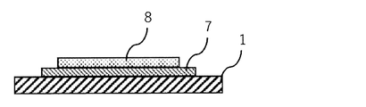
- a semiconductor element 8 such as a power semiconductor element for power, a high-frequency device, or a CPU is mounted on an insulating substrate 7 arranged on the heat sink 1.
- the semiconductor element 8 is made of a material such as silicon (Si), silicon carbide (SiC), gallium nitride (GaN), and gallium arsenide (GaAs).
- a change in length corresponding to a temperature rise of the semiconductor element 8, that is, a linear expansion coefficient is approximately 4 ⁇ 10 ⁇ 6 (1 / K) when the semiconductor element 8 is made of, for example, Si.
- the linear expansion coefficient of the heat sink 1 is, for example, approximately 17 ⁇ 10 ⁇ 6 (1 / K) in the case of being made of Cu, and approximately 23 ⁇ 10 ⁇ 6 (in the case of being made of Al). 1 / K).
- solder or solder is generated due to generation of thermal stress based on a difference in linear expansion coefficient with the semiconductor element 8. Peeling may occur at the joints formed of the material.
- the heat radiation plate 1 has CuW having a smaller linear expansion coefficient.
- Cu alloys such as CuMo and CuCr are used.
- CuW and CuMo have poor extensibility, so that processing such as rolling and pressing is difficult, and an intermediate heat treatment or the like for securing workability is required.
- these Cu alloys have poor wettability with solder and brazing material, their surfaces may require Ni plating or the like.
- the heat radiating plate 1 is constituted by pressing a Cu layer made of Cu on both sides of an FeNi layer made of a FeNi alloy (36 alloy) containing about 36% by mass of Ni, which is a well-known low thermal expansion material.
- a clad material having a layer structure (hereinafter, referred to as “CIC clad material”) is also used.
- This CIC clad material has good workability and a linear expansion coefficient close to that of the above-described semiconductor element, but has a low thermal conductivity of 36 alloy between the Cu layers, so that heat dissipation is caused. There is a problem that the thermal conductivity in the thickness direction of the plate 1 becomes low.
- Patent Document 1 discloses a modified example of a CIC clad material in which a FeNi alloy plate for forming an FeNi layer of the CIC clad material is provided with slit holes to improve thermal conductivity in a thickness direction. (Hereinafter referred to as “CIC- ⁇ cladding material”) has also been proposed.
- the linear expansion coefficient in the longitudinal direction is 8.4 ⁇ 10 ⁇ 6 (1 / K).
- the thermal conductivity in the thickness direction is 21 W / (m ⁇ K), which is a small thermal expansion coefficient suitable for a heat sink.
- the above-mentioned CIC- ⁇ cladding material has a thermal conductivity of 221 W / (m) in the thickness direction when the volume ratio of the high thermal conductive layer made of the high thermal conductive material is 68% by volume. K), which indicates a large thermal conductivity suitable for a heat sink, while the linear expansion coefficient in the longitudinal direction is 11.9 ⁇ 10 ⁇ 6 (1 / K), which is unsatisfactory as a heat sink. Is shown. Further, the above-mentioned CIC- ⁇ clad material has a large thermal expansion amount in the longitudinal direction (rolling direction) and a thermal expansion amount in the width direction of the radiator plate depending on the size and arrangement of the slit portions formed in the FeNi alloy plate. There is a concern about a new problem that a difference occurs (hereinafter, referred to as “anisotropic thermal expansion”).
- An object of the present invention is to have a relatively large thermal conductivity in the thickness direction, to be relatively close to the linear expansion coefficient of the semiconductor element described above, and to have relatively small anisotropy of thermal expansion in the longitudinal direction and the width direction. To provide a heat sink and a method of manufacturing the same.
- a plurality of core members made of a low thermal expansion material are spirally inserted in the longitudinal direction of the high thermal conductive material in a non-contact manner in the longitudinal direction, the width direction and the thickness direction. That is, in the radiator plate of the present invention, a plurality of core members made of a low thermal expansion material are combined with a high heat conductive material serving as a matrix in a spiral shape and in a non-contact state with each other.
- the high thermal conductive material is preferably made of Cu or Cu alloy.
- the low thermal expansion material is made of an FeNi-based alloy.
- the volume ratio of the high thermal conductive material is preferably in the range of 35% by volume to 80% by volume.
- the heat radiating plate of the present invention is charged with a plurality of cores made of a low thermal expansion material in the longitudinal direction of a wire made of a high thermal conductive material having a circular cross section, and in the longitudinal direction, the width direction and the thickness direction of the wire,
- the name of the constituent material of the high heat conductive material is represented by “wire”, but may be, for example, “bar”, “round bar”, or “bar”.
- the twist pitch P of the twisted wire is in the range of 1.5D ⁇ P ⁇ 5.0D with respect to the diameter D of the composite wire.
- the semiconductor device has a relatively large thermal conductivity in the thickness direction, is relatively close to the linear expansion coefficient of the semiconductor element described above, and has relatively small anisotropy of thermal expansion in the longitudinal direction and the width direction.
- a heat sink can be provided.
- the use of the heat sink of the present invention improves the stability and reliability of a semiconductor element such as a power semiconductor element for power, a high-frequency device, or a CPU mounted on the heat sink. Therefore, the present invention is a useful technique.
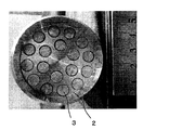
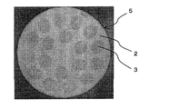
- FIG. 4 is an optical microscope photograph showing a cross section (cross section) in the width direction of a heat sink as an example of the present invention.
- FIG. 4 is a schematic view showing a compounding step in the method for manufacturing a heat sink of the present invention.
- FIG. 4 is a schematic view showing a twisting step in the method for manufacturing a heat sink of the present invention.
- the figure (graph) used for evaluation of the effect of the torsion concerning the thermal conductivity in the thickness direction The photograph which shows an example of the structure of the billet for extrusion using 18 core materials. The photograph which shows an example of a structure of the composite wire which has 18 core materials. 4 is an optical microscope photograph showing a cross section (cross section) in the width direction of a heat sink as an example of the present invention. The photograph which shows an example of arrangement
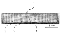
- FIG. 2 shows an example of a cross section in the width direction (transverse cross section) of the heat sink 1 which is an embodiment of the heat sink of the present invention, and its appearance is shown in FIG.
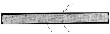
- FIG. 3 a part of the high thermal conductive material is removed by etching to expose the core made of the low thermal expansion material, and the arrangement is shown.
- the longitudinal direction refers to the rolling direction of the sheet material (wire or core material), that is, the front-back direction of the sheet in FIG. 2 and the vertical direction of the sheet in FIG. 3
- the width direction refers to the width direction of the sheet. That is, it refers to the horizontal direction of the paper in FIGS. 2 and 3.
- the heat sink 1 of the present invention is composed of a base material made of a high heat conductive material (hereinafter, referred to as “high heat conductive material 2”) and a plurality of core materials 3 made of a low thermal expansion material.
- the plurality of core members 3 are spirally arranged in the longitudinal direction of the high heat conductive material 2 inside the high heat conductive material 2 and are arranged so as to be in non-contact with each other. That is, in the radiator plate 1 of the present invention, the plurality of core members 3 made of a low thermal expansion material are formed in a spiral shape and are in a non-contact state with each other and are composited with the high heat conductive material 2 serving as a matrix.
- the heat radiating plate 1 has an arrangement structure in which the plurality of core members 3 are arranged continuously in the longitudinal direction, but are discontinuous in the thickness direction and the width direction, over the entire length in the longitudinal direction. It becomes what has. Thereby, the heat radiating plate 1 can have appropriate thermal conductivity in the thickness direction, and has appropriate low thermal expansion in the longitudinal direction and the width direction, that is, suppresses anisotropy of thermal expansion. It becomes possible. As a result, the radiator plate 1 can be suitably used for mounting a power semiconductor element for power, a high-frequency device, or a semiconductor element such as a CPU, and is used for applications requiring both characteristics of low thermal expansion and heat radiation. This is also useful.
- the heat sink 1 shown in FIG. 2 has seven core members 3.
- the number of core materials is not particularly limited.
- the number of cores in the heat sink of the present invention is adjusted to be equal to the linear expansion coefficient of the semiconductor element while being adjusted to the size of the semiconductor element to be radiated. It can be appropriately selected within the range of 50 or more.
- the heat sink of the present invention is appropriately selected according to the size of the semiconductor element to be radiated, for example, with a thickness in the range of 0.3 mm to 4.0 mm and a width in the range of 5 mm to 40 mm. it can.
- the plurality of core members constituting the heat sink of the present invention are spirally arranged in the longitudinal direction.
- the core does not exhibit a spiral shape in the longitudinal direction.
- the core member (center core member 4) located at the center in the width direction cross section (transverse cross section) of the heat sink 1 is deformed through a turning step and a rolling step described later, but has a spiral shape in the longitudinal direction.
- the core material may not be disposed at the center of the high heat conductive material (wire or rod), and may be omitted without disposing the central core material 4 of the radiator plate 1, for example. You can also.
- the heat sink 1 shown in FIG. 2 has a plurality of core members 3 arranged in a spiral. Therefore, the plurality of core members 3 other than the above-described center core member 4 have a predetermined angle with respect to the longitudinal direction and a predetermined angle with respect to the width direction.
- the predetermined angle with respect to the longitudinal direction and the width direction of the core is approximately 45 °.
- the high heat conductive material in the heat sink of the present invention for example, Cu (copper of JIS standard of 1000s), Cu alloy, or Al (aluminum of 1000s of JIS standard), Al alloy, or the like can be applied. It can be appropriately selected according to the material of the semiconductor element to be radiated. Among them, Cu or Cu alloy having excellent heat conductivity is preferable as the high heat conductive material.
- the Cu alloy and the Al alloy in the present invention do not impair the high thermal conductivity that is the gist of the present invention, and in consideration of the bondability with solder and brazing material, thermal expansion, etc.
- a Cu alloy or Al alloy containing Ag in a range of 0.01% to 3.00% by mass a Cu alloy containing Zr in a range of 0.01% to 0.50% by mass or It refers to Al alloy.
- the core material made of a low thermal expansion material is, for example, a FeNi-based alloy such as Fe-36Ni (36 alloy) and Fe-32Ni-5Co, or a Fe-54Co-9.5Cr or the like in mass%.
- FeNiCo-based alloys such as FeCo-based alloys and Fe-29Ni-16Co and Fe-29Ni-17Co can be used.
- the low thermal expansion material is preferably a FeNi-based material whose upper two elements are Fe and Ni such as Fe-36Ni, Fe-32Ni-5Co, Fe-29Ni-16Co and Fe-29Ni-17Co. Alloy.
- the core material made of the low thermal expansion material in the heat sink of the present invention includes the above-mentioned semiconductor element made of silicon (Si), silicon carbide (SiC), gallium nitride (GaN), gallium arsenide (GaAs), etc. From the viewpoint of approximating the coefficient, for example, a wire made of a single metal such as Cr, Mo, or W and having a coefficient of linear expansion of 7.0 ⁇ 10 ⁇ 6 (1 / K) or less can be used.
- the core made of a low thermal expansion material in the heat sink of the present invention may be a wire made of an FeNi-based alloy (for example, 36 alloy) or a FeNiCo-based alloy (for example, Fe-29Ni) depending on the linear expansion coefficient of the above-mentioned various semiconductor elements.
- -16Co or Fe-29Ni-17Co a wire composed of a single metal (for example, Cr, Mo, W) having a coefficient of linear expansion of 7.0 ⁇ 10 ⁇ 6 (1 / K) or less, or It is also possible to appropriately select and use such as combining a plurality of wires having different materials.
- the heat radiating plate of the present invention has a high thermal conductivity constituting a wire (bar). It is preferable that the configuration balance between the material and the plurality of core materials made of the low thermal expansion material be determined accurately. Further, the heat sink of the present invention has a value determined by the volume of the high thermal conductive material / (the volume of the high thermal conductive material + the volume of the low thermal expansion material), that is, the total volume of the high thermal conductive material and the low thermal expansion material is 100% by volume. In this case, it is preferable that the volume ratio of the high thermal conductive material is in the range of 35% by volume to 80% by volume.
- the thermal conductivity of the high thermal conductive material is preferably, for example, at least 10 times larger than the low thermal expansion material to be combined (the thermal conductivity of the 36 alloy is about 13 W / (m ⁇ K)), such as C1020 (JIS standard). It is more preferable that the thermal conductivity is equal to or closer to the thermal conductivity of pure Cu (about 400 W / (m ⁇ K)).
- a low thermal expansion material made of an FeNi alloy or the like has a small coefficient of linear expansion and is suitable for a heat sink, but has a low thermal conductivity and is unsatisfactory with the heat sink.
- a high thermal conductive material made of Cu or a Cu alloy has a high thermal conductivity and is suitable for a heat sink, but has a large linear expansion coefficient and is dissatisfied with the heat sink. For this reason, if the volume ratio of the low thermal expansion material is too large, the heat conductivity of the radiator plate is reduced, and the function of radiating heat generated from the semiconductor element may be reduced.
- the volume ratio of the high thermal conductive material in the heat sink of the present invention is preferably 35% by volume or more in order to approach the thermal conductivity of the semiconductor element, and in order not to largely differ from the linear expansion coefficient of the semiconductor element. It is preferable to make it 80% by volume or less.
- the heat radiating plate of the present invention comprises: (1) A plurality of cores made of a low thermal expansion material are charged in the longitudinal direction of a wire (or a rod) made of a high thermal conductive material having a circular cross section, and the length and width of the wire are made. A composite step of obtaining a composite wire in which the plurality of cores are not in contact with each other in the direction and the thickness direction; and (2) a twisting process in which the composite wire is subjected to a twisting process in a longitudinal direction to obtain a thread wire. It can be obtained by the method for manufacturing a heat sink of the present invention, comprising a turning step and (3) a rolling step of rolling the twisted wire material into a plate shape.
- a rod made of Cu and having a circular cross section is prepared as the high heat conductive material 2 and a plurality of rods made of Fe-36% Ni (36 alloy) are prepared. Is prepared as a low thermal expansion material.
- a plurality of holes for inserting a plurality of core members 3 are provided in the longitudinal direction in the rod material which is the high heat conductive material 2.
- the plurality of holes provided in the rod material, which is the high thermal conductive material 2 are drilled so that the plurality of core members 3 inserted in the holes are not in contact with each other in the longitudinal direction, the width direction, and the thickness direction. .
- the high heat conductive material 2 has a circular cross-section from the viewpoint of twisting the composite wire 5 in which a plurality of cores 3 are inserted in a twisting step described later. Is adopted. Subsequently, a plurality of core members 3 made of a low thermal expansion material are inserted into a plurality of holes formed in a rod material that is a high heat conductive material 2 to obtain a composite wire 5.
- the cross-sectional shape of the core material 3 and the corresponding cross-sectional shape of the hole of the high thermal conductive material 2 are not particularly limited.
- the cross-sectional shape of the core material 3 is preferably a circular cross-section from the viewpoint of the perforability of the rod material as the high thermal conductive material 2 and the availability of the core material 3 as the low thermal expansion material.
- the composite wire 5 shown in FIG. 4 has a seven-core structure in which the core material 3 that is a low thermal expansion material is inserted into all of the seven holes formed in the rod material that is the high heat conductive material 2.
- the number of the core members 3 in the heat sink of the present invention is not particularly limited, and is adjusted to a linear expansion coefficient close to the linear expansion coefficient of the semiconductor element while being adjusted to the size of the semiconductor element to be radiated. Can be selected as appropriate for the purpose of adjusting to.
- the plurality of core materials 3 are made of a rod made of the high thermal conductive material 2 so that the core materials 3 are not in contact with each other. It is preferable to arrange at equal intervals inside a hexagonal outline that can be drawn inscribed in the circular cross section of the material.
- the composite wire 5 in order to obtain the composite wire 5, in order to improve the adhesion between the high thermal conductive material 2 (bar material) made of Cu and the plurality of core materials 3 made of 36 alloy which is a low thermal expansion material, and From the viewpoint of improving workability in consideration of plastic deformability, it is preferable to perform extrusion or wire drawing with heating. In addition, it is preferable to perform a heat treatment step such as softening annealing in each of the above steps, or between the compounding step and the twisting step, or between the twisting step and the rolling step.
- a heat treatment step such as softening annealing in each of the above steps, or between the compounding step and the twisting step, or between the twisting step and the rolling step.
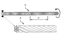
- the composite wire 5 obtained in the compounding step is subjected to a twisting process to obtain a screw circuit member 6.
- the twisted wire 6 is obtained by rotating the chuck and twisting the composite wire 5 having one end fixed and the other end gripped by a chuck or the like.
- the plurality of core members 3 which are not in contact with each other can be spirally arranged at a predetermined angle and a predetermined period with respect to the longitudinal direction.
- a method of unwinding the leading end of the coiled composite wire 5 and sequentially twisting the leading end from the leading end can be applied.
- the twist pitch P of the twisted wire member 6 be in a range of 1.5D ⁇ P ⁇ 5.0D with respect to the diameter (wire diameter) D of the composite wire member 5. It is preferable that the twist pitch P of the twisted wire 6 is 1.5 D or more with respect to the wire diameter D of the composite wire 5, and the composite wire 5 breaks beyond the twist limit, that is, beyond the limit of shear deformation. It is unlikely to cause problems. Further, it is preferable that the twist pitch P of the twisted wire 6 is 5.0 D or less with respect to the wire diameter D of the composite wire 5, and the twisted wire 6 having a sufficient amount of twist (twist angle). Is obtained.
- the radiator plate of the present invention suppresses the application of different thermal strains in the longitudinal direction and the width direction to the semiconductor element to be radiated, thereby deteriorating the performance of the semiconductor element and reducing each of the radiator plate, the insulating substrate, and the semiconductor element. Peeling at the bonding surface can be suppressed.
- the twisted wire member 6 obtained in the twisting step is rolled into a plate shape, and finally rolled so that a plate member having a cross-sectional shape of the heat sink is formed.
- rolling step for example, using a rolling mill in which a rolling stand composed of a pair of upper and lower rolls is arranged in one stage or in multiple stages, rolling is performed in one pass or a plurality of passes so that the heat sink has the shape and dimensions. be able to.
- the plurality of cores 3 arranged inside the high heat conductive material are in non-contact with each other in the longitudinal direction, width direction and thickness direction of the plate. It is preferable to perform rolling at room temperature (room temperature) while appropriately adjusting rolling conditions such as rolling reduction so as to form a structure that is not continuous in the width direction and the thickness direction.
- a heat sink having a seven-core structure which is one embodiment of the heat sink of the present invention, was manufactured.
- a rod material (wire material) made of pure Cu having a diameter of 28 mm as the high thermal conductive material 2 and a plurality of core materials 3 (wire material) made of 36 alloy as the low thermal expansion material were prepared.
- the high thermal conductive material 2 through holes having the same diameter penetrating in the longitudinal direction were formed at seven places which were substantially uniformly arranged in a circular cross section of the high thermal conductive material 2.
- the diameters of the through holes formed in the high thermal conductive material 2 were four levels of 8.3 mm, 7.5 mm, 6.4 mm, and 5.0 mm.
- the core material 3 has a diameter (wire diameter) smaller by 0.3 mm than the diameter of the through hole, and has four levels of 8.0 mm, 7.2 mm, 6.1 mm, and 4.7 mm, and a length of 150 mm.
- the core material 3 having a wire diameter corresponding to each of the seven through holes of the high thermal conductive material 2 was inserted. Then, plugs were fitted to both ends in the longitudinal direction of the high thermal conductive material 2 to produce four types of extruded billets.
- the volume ratio of the high heat conductive material 2 of the four types of extruded billets is about 43% by volume, about 52% by volume, about 66% by volume, respectively, corresponding to the wire diameter of the four types of cores 3. It is about 80% by volume.
- each of the four types of composite wires 5 was subjected to a twisting process.
- the twisted wire 6 was produced by rotating the three-way chuck and twisting the composite wire 5 having one end fixed with a vice and the other end fixed with a three-way chuck.
- 12 types of threaded wire members 6 according to the example of the present invention four levels when the volume ratio of the high thermal conductive material 2 is changed and three levels when the twist pitch P is changed
- four types four levels by changing the volume ratio of the high thermal conductive material 2 according to the comparative example, in which the composite wire 5 was cut into a length of 500 mm without passing through the twisting step, were also produced.
- the twisted wire material 6 according to the example of the present invention and the composite wire material according to the comparative example are each rolled into a plate at room temperature (room temperature) to obtain a flat rectangular wire having a thickness of 1.4 mm and a width of 8.6 mm.
- This rectangular wire is one embodiment of the heat sink of the present invention.
- both ends in the width direction are cut (slit) by 0.3 mm, and cut out so that the length in the rolling direction becomes 8 mm, and the thickness is 1.4 mm ⁇ 8 mm in width ⁇ length.
- the heat sink 1 of 8 mm was produced. The process up to this point is the rolling process.
- the linear expansion coefficient and the thermal conductivity of each of the 12 types of heatsinks of the present invention and the four types of heatsinks of the comparative example manufactured by the above-described manufacturing method were determined.
- the coefficient of linear expansion is measured by using a thermal expansion measuring device (model: TMA8310, manufactured by Rigaku Corporation) to measure the amount of thermal expansion in the length direction and width direction of the heat sink in the range of 25 ° C. to 170 ° C. It was calculated from the measurement results.
- the thermal conductivity was determined based on the Wiedemann-Frantz law by determining the electrical resistivity ⁇ by measuring the electrical resistance in the thickness direction of the heat sink. Table 1 shows the results.
- the CIC clad material has a linear expansion coefficient in the longitudinal direction of 8.4 ⁇ 10 ⁇ 6 (1 / K) when the volume ratio of the high thermal conductive material is 50% by volume, and is small as a heat sink. It shows a suitable coefficient of linear expansion.
- the thermal conductivity in the thickness direction is 21 W / (m ⁇ K), which is small and unsatisfactory as a heat sink.
- the CIC- ⁇ clad material in which a FeNi alloy plate which is a low thermal expansion material and a FeNi layer is provided with slit holes has a thermal conductivity in the thickness direction when the volume ratio of the high thermal conductive material is 68% by volume. Is 221 W / (m ⁇ K), which indicates a large and suitable thermal conductivity as a heat sink.
- the linear expansion coefficient in the longitudinal direction is 11.9 ⁇ 10 ⁇ 6 (1 / K), which is not satisfactory as a heat sink.
- Table 1 also shows these numerical values.
- the low thermal expansion material was 36 alloy, the thermal conductivity (T F ) was 13 W / (m ⁇ K), and the linear expansion coefficient (K F ) was 1.2 ⁇ 10 ⁇ 6 (1 / K).
- T F thermal conductivity
- K F linear expansion coefficient
- V C when V C is 80 vol%, about the thermal conductivity of the heat radiating plate 315W / (m ⁇ K), the linear expansion coefficient was about 13.7 ⁇ 10 -6 (1 / K ).
- the thermal conductivity of a Si substrate (Si single crystal) frequently used for a semiconductor element is about 168 W / (m ⁇ K), and the linear expansion coefficient is about 3.9 ⁇ 10 ⁇ 6 (1 / K).
- Table 1 also shows these numerical values.
- Examples 4 to 6 of the present invention shows that when the volume ratio of the high thermal conductive material is 52% by volume, the linear expansion coefficient in the longitudinal direction tends to decrease as the twist pitch decreases. This tendency is considered to be attributable to the fact that the density of the low thermal expansion material in the longitudinal direction relatively increases as the twist pitch decreases.
- examples 7 to 9 and the present invention examples 10 to 12 when the volume ratio of the high thermal conductive material is 66% by volume and 80% by volume, the linear expansion coefficient in the longitudinal direction decreases when the twist pitch becomes small. There is a peculiar tendency to increase. It is considered that this tendency occurs because the volume ratio of the high thermal conductive material is large, so that the twist pitch is small and the density of the low thermal expansion material in the longitudinal direction is relatively small.
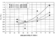
- LI / K LC is shown in Table 2, and a graph based thereon is shown in FIG.
- K LI / K LC crosses the line of 1 between approximately 40% to 45% by volume and approximately 60% to 70% by volume. Between. It is considered that the coefficient of linear expansion in the longitudinal direction is not affected by torsion in the line where K LI / K LC is 1. The effect of torsion is obtained and the coefficient of linear expansion in the longitudinal direction is reduced.
- the lower limit of the volume ratio of the high heat conductive material of the heat sink of the present invention is preferably at least 40% by volume, more preferably at least 45% by volume, still more preferably at least 50% by volume, and preferably at the upper limit.
- the range of the volume ratio of the high heat conductive material of the heat sink of the present invention can be combined with the above lower limit and upper limit according to the application.
- the heatsink of the present invention is characterized in that the low thermal expansion material (see the plurality of cores 3 shown in FIG. 5) inside the high thermal conductivity material is arranged in a special spiral shape, and the It was found that the coefficient of linear expansion was relatively close to that of the conventional CIC clad material and CIC- ⁇ clad material, and that the coefficient of linear expansion in the longitudinal direction was closer to that of the semiconductor element (Si substrate).
- the heatsink of the present invention is twisted because the low thermal expansion material (see the plurality of cores 3 shown in FIG. 5) inside the high thermal conductivity material is arranged in a special spiral shape. It was found that the coefficient of linear expansion in the width direction was smaller than that of the heat radiating plate of the comparative example having no heat sink.
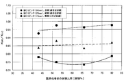
- the heat sink of the present invention obtains the effect of torsion and reduces the linear expansion coefficient in the width direction by setting the volume ratio of the high heat conductive material to 35% by volume or more and 80% by volume or less. We can see that we can do it.
- the volume ratio of the high thermal conductive material in consideration of the linear approximation line and the quadratic approximation line shown in FIG. 7, preferably 75% by volume or less, more preferably 70% by volume or less, and still more preferably It turns out that it is 65 volume% or less.
- the anisotropy shown in Table 1 is evaluated by the absolute value (
- the anisotropy of the linear expansion of the present invention example and the comparative example tends to be more suppressed based on the change tendency of the linear expansion coefficient in the longitudinal direction and the width direction when the volume ratio of the high thermal conductive material is reduced. It turns out that there is.
- the heatsink of the present invention has a low thermal expansion material (see the plurality of cores 3 shown in FIG. 5) inside the high heat conduction material, and is arranged in a special spiral shape. It has been found that the anisotropy of linear expansion is suppressed as compared with the heat sink of the comparative example having relatively small anisotropy and having no twist.
- the thermal conductivity in the thickness direction is larger than that of the heatsink of the comparative example having a relatively large thermal conductivity and no twist.
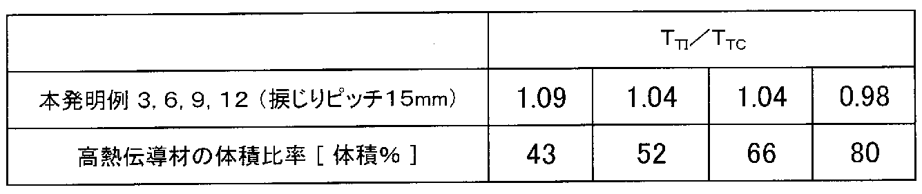
- the thermal conductivity (T TI ) in the thickness direction of each of Inventive Examples 3, 6, 9, and 12 is divided by the thermal conductivity (T TC ) in the thickness direction of Comparative Examples 1 to 4, respectively.
- Table 4 shows the values (T TI / T TC ) obtained in this manner
- FIG. 8 shows a graph based on the values.
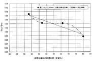
- T TI / T TC crosses the line of 1 at about 75% by volume.
- the thermal conductivity in the thickness direction is not affected by the torsion is the line where T TI / T TC is 1, and the thermal conductivity in the thickness direction is large due to the effect of the torsion.
- the volume ratio of the high thermal conductive material of the heat sink of the present invention is preferably 35% by volume or more and 75% by volume or less, the effect of twisting is obtained, and the thermal conductivity in the thickness direction is reduced. Can be bigger.
- the volume ratio is preferably 70% by volume, and more preferably 65% by volume.
- the thermal conductivity in the thickness direction of the present invention example is particularly larger than that of the CIC clad material.
- the thermal conductivity in the thickness direction of the present invention example is particularly larger than that of the CIC clad material.
- the thermal conductivity in the thickness direction is about 10 times larger than that of the CIC clad material, and when the volume ratio is 43% by volume (Example 3 of the present invention). ) Is more than 6 times larger.
- the thermal conductivity in the thickness direction of the present invention example was CIC- ⁇ when the volume ratio of the high heat conductive material was 66% by volume (Example 9 of the present invention). It can be seen that it is equivalent to the ⁇ -clad material, and is clearly larger than the CIC- ⁇ -clad material at 80% by volume (Example 12 of the present invention).
- the volume ratio of the high thermal conductive material of the heat sink of the present invention is more than 65% by volume (preferably 70% by volume or more)
- the coefficient of linear expansion in the thickness direction is higher than that of the CIC- ⁇ clad material. It can be seen that also becomes larger.
- the heatsink of the present invention has a low thermal expansion material (see a plurality of cores 3 shown in FIG. 5) inside a high thermal conductive material, and is arranged in a special spiral shape. It has been found that the CIC- ⁇ clad material may have a larger coefficient of linear expansion in the thickness direction in some cases. In this case, since the thermal conductivity in the thickness direction of the heat radiating plate of the present invention is larger than the thermal conductivity of the semiconductor element (Si substrate), it can be understood that the heat sink is effective for heat removal and heat radiation from the semiconductor element. .
- a heat sink having an 18-core structure which is one embodiment of the heat sink of the present invention, was manufactured.
- the method of manufacturing a heatsink having an 18-core structure is substantially the same as that of the above-described 7-core structure.
- a rod made of pure Cu having a diameter of 62 mm as the high thermal conductive material 2 and a plurality of cores 3 made of 36 alloy as the low thermal expansion material were prepared.
- the through holes in the longitudinal direction of the high heat conductive material 2 were formed at 18 locations that were substantially uniformly arranged in a circular cross section excluding the center of the high heat conductive material 2.
- the diameter of the through hole was 9 mm.
- the diameter of the core material 3 was 8.6 mm.
- the core material 3 is inserted into each of the 18 through-holes of the high thermal conductive material 2 (bar), and plugs are fitted into both ends of the high thermal conductive material 2 (bar) in the longitudinal direction.
- a billet was prepared. In this case, the volume ratio of the high heat conductive material 2 in the extruded billet is about 62% by volume.
- the extruded billet was extruded to a diameter of 22.5 mm while being heated to about 400 ° C.
- wire drawing was performed to reduce the diameter, and a composite wire 5 having a cross section shown in FIG. 10 and having a diameter (wire diameter) of 6 mm was produced.
- the composite wire 5 was cut at a length of 2 m, and then softened by heat treatment at about 700 ° C. for 1 hour.
- the process up to here is the compounding process.
- the composite wire 5 was twisted.
- the twisted wire 6 was produced by rotating the three-way chuck and twisting the composite wire 5 having one end fixed with a vice and the other end fixed with a three-way chuck.
- the twisted wire material 6 is rolled into a plate shape at normal temperature (room temperature) to obtain a flat rectangular wire having a thickness of 1.4 mm and a width of 15 mm having a cross section (cross section) shown in FIG. Produced.
- This rectangular wire is one embodiment of the heat sink of the present invention.
- FIG. 12 shows the appearance of this rectangular wire.
- a part of the high thermal conductive material 2 is removed by etching to expose the core material 3 made of the low thermal expansion material, and the arrangement configuration is shown.
- both ends in the width direction of the rectangular wire are cut (slit) by 0.5 mm, and cut out so that the length in the rolling direction becomes 14 mm, and the heat radiation of 1.4 mm in thickness ⁇ 14 mm in width ⁇ 14 mm in length is performed. Plate 1 was produced. The process up to this point is the rolling process.
- the linear expansion coefficient and the thermal conductivity of the heatsink as an example of the present invention manufactured by the above-described manufacturing method were determined.
- the coefficient of thermal expansion is measured by measuring the amount of thermal expansion in the length direction and width direction of the heat sink in the range of 25 ° C. to 170 ° C. using a thermal expansion measuring device (model: TMA8310) manufactured by Rigaku Corporation. It was calculated from the measurement results.
- the thermal conductivity was determined based on the Wiedemann-Frantz law by determining the electrical resistivity ⁇ by measuring the electrical resistance in the thickness direction of the heat sink.
- the linear expansion coefficient in the longitudinal direction (rolling direction) of the heatsink having an 18-core structure is about 8.5 ⁇ 10 ⁇ 6 (1 / K), and the linear expansion coefficient in the width direction is about 8.8 ⁇ 10 ⁇ 6. (1 / K).
- the linear expansion anisotropy is about 0.3 ⁇ 10 ⁇ 6 (1 / K).
- the thermal conductivity in the thickness direction of the heatsink having an 18-core structure was about 260 W / (m ⁇ K).
- the anisotropic thermal expansion of the 18-core heatsink is suppressed to a small value, and the linear expansion coefficient in the longitudinal direction is reduced to a CIC- ⁇ clad material (volume ratio of the high thermal conductive material is 68 vol.) Shown in Table 1. %), which is close to the linear expansion coefficient of, for example, a Si substrate (Si single crystal) frequently used in semiconductor devices.
- the 18-core heatsink has a thermal conductivity in the thickness direction that is about 18% larger than that of the CIC- ⁇ clad material (volume ratio of the high thermal conductive material is 68% by volume) shown in Table 1, and is used for semiconductor elements.
- the thermal conductivity is about 55% larger than the thermal conductivity of a frequently used Si substrate (Si single crystal), for example. From these results, it is found that the heat sink of the present invention has a low thermal expansion material (see a plurality of core members 3 shown in FIG. 5) inside the high heat conductive material, which is arranged in a special spiral shape. Is reduced, the coefficient of linear expansion in the longitudinal direction is closer to the semiconductor element (Si substrate) than in the conventional CIC- ⁇ clad material, and the thermal conductivity in the thickness direction is increased. It was found to be effective for heat and heat dissipation.
Landscapes
- Physics & Mathematics (AREA)
- Thermal Sciences (AREA)
- Engineering & Computer Science (AREA)
- Microelectronics & Electronic Packaging (AREA)
- Cooling Or The Like Of Semiconductors Or Solid State Devices (AREA)
- Cooling Or The Like Of Electrical Apparatus (AREA)
Abstract
厚さ方向に大きな熱伝導率を有し、半導体素子の線膨張率に近く、長手方向および幅方向に係る熱膨張の異方性が小さい、放熱板およびその製造方法を提供する 低熱膨張材からなる複数の芯材が、高熱伝導材の長手方向、幅方向および厚さ方向において互いに非接触で、長手方向に螺旋状に装入されている放熱板とする。この放熱板は、円形断面を有する高熱伝導材からなる線材の長手方向に低熱膨張材からなる複数の芯材を装入し、前記線材の長手方向および幅方向において、前記複数の芯材が互いに非接触となる複合線材を得る複合化工程と、前記複合線材の長手方向に捩じり加工を施して捩回線材を得る捩回工程と、前記捩回線材を板状に圧延する圧延工程を有する製造方法で得ることができる。この場合、前記捩回線材の捩じりピッチPは、前記複合線材の直径Dに対して1.5D≦P≦5.0Dの範囲にすることが好ましい。
Description
本発明は、例えば、電力用パワー半導体素子や、高周波デバイスあるいはCPU等の半導体素子が実装される、放熱板およびその製造方法に関するものである。
例えば、図1に示すように、電力用パワー半導体素子や高周波デバイスあるいはCPU等の半導体素子8は、放熱板1上に配置された絶縁基板7上に実装される。半導体素子8は、例えば、シリコン(Si)、炭化ケイ素(SiC)、窒化ガリウム(GaN)、ガリウムひ素(GaAs)などの材料により構成されている。ここで、半導体素子8の温度上昇に対応する長さの変化、すなわち線膨張率は、例えばSiにより構成されている場合は、概ね4×10⁻⁶(1/K)である。一方、放熱板1の線膨張率は、例えば、Cuにより構成されている場合は概ね17×10-6(1/K)であり、Alにより構成されている場合は概ね23×10-6(1/K)である。このため、半導体素子8を実装するときに、放熱板1としてCuまたはAlにより構成されている板材を用いると、半導体素子8との線膨張率の差に基づく熱応力の発生により、はんだまたはろう材で形成される接合部分で剥離が生じる場合がある。
これに対して、放熱板1には、上記の半導体素子8との線膨張率およびセラミックス等で構成される絶縁基板7との線膨張率を整合させる目的で、線膨張率がより小さいCuW、CuMo、CuCr等のCu合金が用いられている。これらのCu合金の中でもCuWやCuMoは、伸延性に乏しいため、圧延やプレス等の加工が困難であり、加工性を確保するための中間熱処理等が必要となる。また、これらのCu合金は、はんだおよびろう材との濡れ性に劣るため、表面にNiめっき等を必要とする場合がある。
一方、放熱板1には、低熱膨張材料として著名な約36質量%のNiを含むFeNi合金(36アロイ)からなるFeNi層の両面に、CuからなるCu層が圧接されて構成された、3層構造のクラッド材(以下、「CICクラッド材」という。)も用いられている。このCICクラッド材は、加工性が良好で、かつ線膨張率は上記の半導体素子に近いものの、Cu層とCu層の間に、熱伝導率が小さい36アロイを介在させているために、放熱板1の厚さ方向の熱伝導率が低くなってしまうという問題がある。
また、特許文献1では、CICクラッド材のFeNi層を構成するためのFeNi合金板にスリット孔を設けた板を採用して、厚さ方向の熱伝導性を改善した、CICクラッド材の変形例(以下、「CIC-αクラッド材」という。)からなる低熱膨張複合放熱板も提案されている。
上記したCICクラッド材は、特許文献1の開示によると、CuからなるCu層の体積比率が50体積%のときに、長手方向の線膨張率は8.4×10⁻⁶(1/K)であり、放熱板として好適な小さな線膨張率を示す一方、厚さ方向の熱伝導率は21W/(m・K)であり、放熱板として不満な小さな熱伝導率を示す。
また、上述したCIC-αクラッド材は、特許文献1の開示によると、高熱伝導材からなる高熱伝導層の体積比率が68体積%のときに、厚さ方向の熱伝導率は221W/(m・K)であり、放熱板として好適な大きな熱伝導率を示す一方、長手方向の線膨張率は11.9×10-6(1/K)であり、放熱板として不満な大きな線膨張率を示す。
また、上記したCIC-αクラッド材は、FeNi合金板に形成されるスリット部のサイズや配置によっては、放熱板の長手方向(圧延方向)の熱膨張量と幅方向の熱膨張量とに大きな差が生じる(以下、「熱膨張の異方性」という。)という、新たな問題が懸念される。
また、上記したCIC-αクラッド材は、FeNi合金板に形成されるスリット部のサイズや配置によっては、放熱板の長手方向(圧延方向)の熱膨張量と幅方向の熱膨張量とに大きな差が生じる(以下、「熱膨張の異方性」という。)という、新たな問題が懸念される。
本発明の目的は、厚さ方向に比較的大きな熱伝導率を有し、上記した半導体素子の線膨張率に比較的近く、長手方向および幅方向に係る熱膨張の異方性が比較的小さい、放熱板およびその製造方法を提供することにある。
本発明の放熱板は、低熱膨張材からなる複数の芯材が、高熱伝導材の長手方向、幅方向および厚さ方向において互いに非接触で、長手方向に螺旋状に装入されている。つまり、本発明の放熱板は、低熱膨張材からなる複数の芯材が、螺旋状をなし、かつ、互いに非接触な状態で、マトリックスとなる高熱伝導材と複合化されている。
前記高熱伝導材は、CuまたはCu合金からなることが好ましい。
前記低熱膨張材は、FeNi系合金からなることが好ましい。
前記高熱伝導材の体積比率は、35体積%以上80体積%以下の範囲にあることが好ましい。
本発明の放熱板は、円形断面を有する高熱伝導材からなる線材の長手方向に低熱膨張材からなる複数の芯材を装入し、前記線材の長手方向、幅方向および厚さ方向において、前記複層の芯材が互いに非接触となる複合線材を得る複合化工程と、前記複合線材の長手方向に捩じり加工を施して捩回線材を得る捩回工程と、前記捩回線材を板状に圧延する圧延工程を有する製造方法で得ることができる。なお、本発明では、高熱伝導材の構成材料の呼称を「線材」で代表するが、例えば「棒材」「丸棒」「バー材」などの呼称であってもよい。
前記捩回線材の捩じりピッチPは、前記複合線材の直径Dに対して1.5D≦P≦5.0Dの範囲にすることが好ましい。
本発明によれば、厚さ方向に比較的大きな熱伝導性を有し、上記した半導体素子の線膨張率に比較的近く、長手方向および幅方向に係る熱膨張の異方性が比較的小さい、放熱板を提供することができる。本発明の放熱板を用いれば、この放熱板上に実装される、例えば、電力用パワー半導体素子や、高周波デバイスあるいはCPU等の半導体素子の安定性および信頼性が向上される。よって、本発明は有用な技術となる。
本発明の放熱板は、低熱膨張材からなる複数の芯材が、高熱伝導材の長手方向、幅方向および厚さ方向において互いに非接触で、その高熱伝導材の長手方向に螺旋状に装入されている。ここで、図2に、本発明の放熱板の一実施形態となる放熱板1の幅方向断面(横断面)の一例を示し、その外観を図3に示す。なお、図3では、高熱伝導材の一部をエッチングによって除去して、低熱膨張材からなる芯材を露出させ、その配置構成を示している。また、本発明では、長手方向とは板材(線材、芯材)の圧延方向、すなわち、図2における紙面前後方向、および図3における紙面上下方向のことをいい、幅方向とは板材の幅方向、すなわち、図2および図3にける紙面左右方向のことをいう。
本発明の放熱板1は、高熱伝導材からなる母材(以下、「高熱伝導材2」という。)と、低熱膨張材からなる複数の芯材3とにより構成されている。複数の芯材3は、高熱伝導材2の内部において、高熱伝導材2の長手方向に螺旋状で、互いに非接触となるように配置されている。つまり、本発明の放熱板1は、低熱膨張材からなる複数の芯材3が、螺旋状をなし、かつ、互いに非接触な状態で、マトリックスとなる高熱伝導材2と複合化されている。したがって、放熱板1は、その長手方向の全長において、複数の芯材3が長手方向には連続して配置されているのに対して、厚さ方向および幅方向には不連続となる配置構造を有するものになる。これにより、放熱板1は、厚さ方向において相応の熱伝導性を有することが可能になるとともに、長手方向および幅方向において相応の低熱膨張性を有する、すなわち熱膨張の異方性を抑制することが可能になる。その結果、放熱板1は、電力用パワー半導体素子や、高周波デバイスあるいはCPU等の半導体素子の実装に好適に用いることができるし、さらに低熱膨張性および放熱性の両特性が要求される用途に対しても有用なものとなる。
図2に示す放熱板1は、7本の芯材3を有している。しかし、本発明の放熱板を構成する場合、芯材の本数は、特に制限されない。本発明の放熱板における芯材の本数は、放熱対象となる半導体素子のサイズに合わせるとともに、半導体素子の線膨張率に近似した線膨張率となるように調整することを目的に、例えば2本以上50本以下の範囲で、適宜選択できる。また、本発明の放熱板は、放熱対象となる半導体素子のサイズに合わせて、例えば、厚さを0.3mm以上4.0mm以下の範囲で、幅を5mm以上40mm以下の範囲で、適宜選択できる。
また、本発明の放熱板を構成する複数の芯材は、長手方向において螺旋状に配置されている。しかし、高熱伝導材の中心部に芯材が配置された場合、その芯材(図2に示す中心芯材4を参照)が長手方向において螺旋状を呈しないことは、いうまでもない。例えば、放熱板1の幅方向断面(横断面)において中央部に位置する芯材(中心芯材4)は、後述する旋回工程および圧延工程を経て変形しているが、長手方向において螺旋状を呈していない。なお、本発明の放熱板において、芯材が高熱伝導材(線材または棒材)の中心部に配置されていなくてもよく、例えば、放熱板1の中心芯材4を配置せずに省略することもできる。
図2に示す放熱板1は、複数の芯材3が螺旋状に配置されている。そのため、上記した中心芯材4以外の複数の芯材3は、長手方向に対して所定の角度を有するとともに、幅方向に対しても所定の角度を有して配置される構造になる。本発明の放熱板は、その長手方向および幅方向における熱膨張の異方性を抑制する観点から、芯材の長手方向および幅方向に対する上記所定の角度が概ね45°であることが好ましい。この構成を有する放熱板を用いることにより、放熱対象となる半導体素子に、長手方向、幅方向および厚さ方向で異なる熱歪が加わり難くなるため、半導体素子の性能低下や、放熱板、絶縁基板、半導体素子の各接合面における剥離を抑制することができる。
本発明の放熱板における高熱伝導材には、例えば、Cu(JIS規定の1000番台の銅)、Cu合金、あるいはAl(JIS規定の1000番台のアルミニウム)、Al合金等を適用することができ、放熱対象の半導体素子の材質等により適宜選択できる。中でも、高熱伝導材として好ましくは、熱伝導性に優れるCuまたはCu合金である。ここで、本発明におけるCu合金およびAl合金は、本発明の主旨である高熱伝導性を阻害せず、はんだやろう材との接合性や、熱膨張等を考慮して、CuまたはAlに対して、例えば、Agを0.01質量%以上3.00質量%以下の範囲で含むCu合金またはAl合金、あるいはZrを0.01質量%以上0.50質量%以下の範囲で含むCu合金またはAl合金のことをいう。
本発明の放熱板における低熱膨張材からなる芯材には、質量%で、例えば、Fe-36Ni(36アロイ)およびFe-32Ni-5CoなどのFeNi系合金、Fe-54Co-9.5CrなどのFeCo系合金、Fe-29Ni-16CoおよびFe-29Ni-17CoなどのFeNiCo系合金を適用することができる。中でも、低熱膨張材として好ましくは、Fe-36Ni、Fe-32Ni-5Co、Fe-29Ni-16CoおよびFe-29Ni-17Coなど、含有量が多い方から上位二つの元素がFeとNiであるFeNi系合金である。
また、本発明の放熱板における低熱膨張材からなる芯材には、上記したシリコン(Si)、炭化ケイ素(SiC)、窒化ガリウム(GaN)、ガリウムひ素(GaAs)等からなる半導体素子と線膨張率を近似させる観点から、例えば、Cr、Mo、Wなどの単一金属からなり、線膨張率が7.0×10⁻⁶(1/K)以下の線材を用いることができる。また、本発明の放熱板における低熱膨張材からなる芯材は、上記した各種半導体素子の線膨張率に応じて、FeNi系合金(例えば36アロイ)からなる線材、FeNiCo系合金(例えばFe-29Ni-16CoまたはFe-29Ni-17Co)からなる線材、線膨張率が7.0×10-6(1/K)以下の単一金属(例えばCr、Mo、W)からなる線材、または、上記した材質が異なる線材を複数組み合せるなど、適宜選択して用いることもできる。
本発明の放熱板は、厚さ方向の高熱伝導性を確保し、かつ、長手方向と幅方向とで生じる熱膨張の異方性を抑制するには、線材(棒材)を構成する高熱伝導材と、低熱膨張材からなる複数の芯材との構成バランスを的確に決めることが好ましい。また、本発明の放熱板は、高熱伝導材の体積/(高熱伝導材の体積+低熱膨張材の体積)で求まる値、すなわち、高熱伝導材と低熱膨張材の体積の合計を100体積%としたときに、高熱伝導材の体積比率を35体積%以上80体積%以下の範囲にすることが好ましい。なお、高熱伝導材の熱伝導率は、組み合せる低熱膨張材(36アロイの熱伝導率は13W/(m・K)程度)の例えば10倍以上大きい値が好ましく、例えばC1020(JIS規格)などの純Cuの熱伝導率(約400W/(m・K))と同等か、その値により近いほど好ましい。
FeNi系合金などからなる低熱膨張材は、線膨張率が小さく放熱板に適するが、熱伝導率が小さく放熱板には不満である。また、CuまたはCu合金などからなる高熱伝導材は、熱伝導率が大きく放熱板に適するが、線膨張率が大きく放熱板には不満である。このため、低熱膨張材の体積比率を大きくしすぎると、放熱板の熱伝導率が低下してしまい、半導体素子からの発熱を放熱する機能が低下する場合がある。また、高熱伝導材の体積比率を大きくしすぎると、放熱板の線膨張率が半導体素子の線膨張率と乖離してしまい、半導体素子が放熱板から剥離する場合がある。こうした観点から、本発明の放熱板における高熱伝導材の体積比率は、半導体素子の熱伝導率に近づけるために35体積%以上とすることが好ましく、半導体素子の線膨張率と大きく乖離させないために80体積%以下にすることが好ましい。
本発明の放熱板は、(1)円形断面を有する高熱伝導材からなる線材(または棒材)の長手方向に低熱膨張材からなる複数の芯材を装入し、前記線材の長手方向、幅方向および厚さ方向において、前記複数の芯材が互いに非接触となる複合線材を得る複合化工程と、(2)前記複合線材の長手方向に捩じり加工を施して捩回線材を得る捩回工程と、(3)前記捩回線材を板状に圧延する圧延工程を有する、本発明の放熱板の製造方法で得ることができる。
(1)複合化工程
複合化工程では、図4に示すように、例えば、Cuからなり円形断面を有する棒材を高熱伝導材2として準備し、Fe-36%Ni(36アロイ)からなる複数の芯材3を低熱膨張材として準備する。このとき、高熱伝導材2である棒材には、複数の芯材3を装入するための複数の穴を長手方向に設ける。高熱伝導材2である棒材に設ける複数の穴は、その穴に装入した複数の芯材3が長手方向、幅方向および厚さ方向において、互いに非接触となるように、穴開け加工する。なお、本発明の放熱板の製造方法では、後述する捩回工程で、複数の芯材3が装入された複合線材5に捩じり加工を施す観点から、高熱伝導材2には円形断面を採用する。続いて、低熱膨張材からなる複数の芯材3を、高熱伝導材2である棒材に形成した複数の穴に装入し、複合線材5を得る。ここで、芯材3の断面形状およびそれに対応する高熱伝導材2の穴の断面形状は、特に制限されない。なお、芯材3の断面形状は、高熱伝導材2である棒材の穴開け性や、低熱膨張材である芯材3の入手性の観点から、円形断面を採用することが好ましい。
複合化工程では、図4に示すように、例えば、Cuからなり円形断面を有する棒材を高熱伝導材2として準備し、Fe-36%Ni(36アロイ)からなる複数の芯材3を低熱膨張材として準備する。このとき、高熱伝導材2である棒材には、複数の芯材3を装入するための複数の穴を長手方向に設ける。高熱伝導材2である棒材に設ける複数の穴は、その穴に装入した複数の芯材3が長手方向、幅方向および厚さ方向において、互いに非接触となるように、穴開け加工する。なお、本発明の放熱板の製造方法では、後述する捩回工程で、複数の芯材3が装入された複合線材5に捩じり加工を施す観点から、高熱伝導材2には円形断面を採用する。続いて、低熱膨張材からなる複数の芯材3を、高熱伝導材2である棒材に形成した複数の穴に装入し、複合線材5を得る。ここで、芯材3の断面形状およびそれに対応する高熱伝導材2の穴の断面形状は、特に制限されない。なお、芯材3の断面形状は、高熱伝導材2である棒材の穴開け性や、低熱膨張材である芯材3の入手性の観点から、円形断面を採用することが好ましい。
また、図4に示す複合線材5は、高熱伝導材2である棒材に形成された7つの穴のすべてに低熱膨張材である芯材3が装入されている、7芯構造である。なお、本発明の放熱板における芯材3の本数は、特に制限されるものではなく、放熱対象となる半導体素子のサイズに合わせるとともに、半導体素子の線膨張率に近似した線膨張率となるように調整することを目的に、適宜選択できる。また、上記した複合化工程では、低熱膨張材である芯材3の均一配置という観点から、複数の芯材3を、芯材3が互いに非接触となるように、高熱伝導材2である棒材の円形断面に内接して描ける六角形の輪郭の内側に等間隔で配置することが好ましい。
上記した複合化工程では、複合線材5を得るために、Cuからなる高熱伝導材2(棒材)と低熱膨張材である36アロイからなる複数の芯材3との密着性を高める観点、および塑性変形能を考慮して加工性を向上させる観点から、押出し加工または伸線加工を加熱を伴って行うことが好ましい。これに加えて、上記の各工程内において、あるいは、複合化工程と捩回工程との間、捩回工程と圧延工程との間において、軟化焼鈍などの熱処理工程を行うことが好ましい。
(2)捩回工程
捩回工程では、図5に示すように、複合化工程で得た複合線材5に捩じり加工を施し、捩回線材6を得る。具体的には、一端を固定し、他端をチャックなどで把持した状態の複合線材5を、チャックを回転させて捩じることにより、捩回線材6を得る。これにより、互いに非接触の状態にある複数の芯材3を、長手方向に対して所定の角度および周期で螺旋状に配置することができる。捩回数工程では、量産性の観点から、例えば、コイル状に巻かれた複合線材5の先端部を巻出しながら、その先端部から順に捩じり加工を施す方法などが適用できる。
捩回工程では、図5に示すように、複合化工程で得た複合線材5に捩じり加工を施し、捩回線材6を得る。具体的には、一端を固定し、他端をチャックなどで把持した状態の複合線材5を、チャックを回転させて捩じることにより、捩回線材6を得る。これにより、互いに非接触の状態にある複数の芯材3を、長手方向に対して所定の角度および周期で螺旋状に配置することができる。捩回数工程では、量産性の観点から、例えば、コイル状に巻かれた複合線材5の先端部を巻出しながら、その先端部から順に捩じり加工を施す方法などが適用できる。
捩回工程では、捩回線材6の捩じりピッチPを、複合線材5の直径(線径)Dに対して1.5D≦P≦5.0Dの範囲にすることが好ましい。捩回線材6の捩じりピッチPが複合線材5の線径Dに対して1.5D以上であることは好ましく、複合線材5が捩回限界、すなわち、せん断変形の限界を超えて破断する不具合が発生しにくい。また、捩回線材6の捩じりピッチPが複合線材5の線径Dに対して5.0D以下であることは好ましく、十分な捩じり量(捩回角度)を有する捩回線材6が得られる。捩回線材6の捩じり量が十分であると、圧延工程で捩回線材6を板状に圧延して放熱板を得た際に、放熱板の長手方向および幅方向における線膨張率の差を小さくすることができるため、放熱板の熱膨張の異方性を抑制できる。これにより、本発明の放熱板は、放熱対象となる半導体素子に、長手方向と幅方向で異なる熱歪が加わることを抑えて、半導体素子の性能低下や放熱板、絶縁基板、半導体素子の各接合面における剥離を抑制することができる。
(3)圧延工程
圧延工程では、捩回工程で得た捩回線材6を板状に圧延し、最終的に放熱板の断面形状を有する板材が形成されるように圧延する。圧延工程では、例えば、上下一対のロールで構成される圧延スタンドを一段あるいは多段に配置した圧延機を用いて、1パスあるいは複数回のパスで、放熱板の形状寸法となるように、圧延することができる。圧延工程では、最終的に放熱板の断面形状を有する板材において、高熱伝導材の内部に配置された複数の芯材3が、その板材の長手方向、幅方向および厚さ方向において互いに非接触で、幅方向および厚さ方向で連なっていない構造となるように、圧下率などの圧延条件を適宜調整しながら常温(室温)で圧延することが好ましい。
圧延工程では、捩回工程で得た捩回線材6を板状に圧延し、最終的に放熱板の断面形状を有する板材が形成されるように圧延する。圧延工程では、例えば、上下一対のロールで構成される圧延スタンドを一段あるいは多段に配置した圧延機を用いて、1パスあるいは複数回のパスで、放熱板の形状寸法となるように、圧延することができる。圧延工程では、最終的に放熱板の断面形状を有する板材において、高熱伝導材の内部に配置された複数の芯材3が、その板材の長手方向、幅方向および厚さ方向において互いに非接触で、幅方向および厚さ方向で連なっていない構造となるように、圧下率などの圧延条件を適宜調整しながら常温(室温)で圧延することが好ましい。
<7芯構造の放熱板>
本発明の放熱板の一実施形態となる、7芯構造の放熱板を作製した。まず、図4に示すように、高熱伝導材2として直径が28mmの純Cuからなる棒材(線材)と、低熱膨張材として36アロイからなる複数の芯材3(線材)を準備した。高熱伝導材2には、その長手方向に貫通する同径の貫通孔を、高熱伝導材2の円形断面内に略均一配置される7か所に形成した。高熱伝導材2に形成する貫通穴の直径は、8.3mm、7.5mm、6.4mm、5.0mmの4水準とした。芯材3は、貫通穴の直径よりも0.3mm小さい直径(線径)とし、8.0mm、7.2mm、6.1mm、4.7mmの4水準とし、長さを150mmとした。上記した高熱伝導材2の7つの貫通孔のそれぞれに、これに対応する線径の芯材3を装入した。そして、この高熱伝導材2の長手方向の両端部にプラグを嵌め込み、4種類の押出し用ビレットを作製した。この場合、4種類の押出し用ビレットの高熱伝導材2の体積比率は、4種類の芯材3の線径に対応して、それぞれ、約43体積%、約52体積%、約66体積%、約80体積%となる。
本発明の放熱板の一実施形態となる、7芯構造の放熱板を作製した。まず、図4に示すように、高熱伝導材2として直径が28mmの純Cuからなる棒材(線材)と、低熱膨張材として36アロイからなる複数の芯材3(線材)を準備した。高熱伝導材2には、その長手方向に貫通する同径の貫通孔を、高熱伝導材2の円形断面内に略均一配置される7か所に形成した。高熱伝導材2に形成する貫通穴の直径は、8.3mm、7.5mm、6.4mm、5.0mmの4水準とした。芯材3は、貫通穴の直径よりも0.3mm小さい直径(線径)とし、8.0mm、7.2mm、6.1mm、4.7mmの4水準とし、長さを150mmとした。上記した高熱伝導材2の7つの貫通孔のそれぞれに、これに対応する線径の芯材3を装入した。そして、この高熱伝導材2の長手方向の両端部にプラグを嵌め込み、4種類の押出し用ビレットを作製した。この場合、4種類の押出し用ビレットの高熱伝導材2の体積比率は、4種類の芯材3の線径に対応して、それぞれ、約43体積%、約52体積%、約66体積%、約80体積%となる。
続いて、4種類の押出し用ビレットを、約400℃に加熱した状態で、直径が12mmとなるように押出し加工して、4種類のビレットを作製した。続いて、直径が12mmの4種類のビレットのそれぞれを伸線加工して細径化し、直径(線径)が5mmの4種類の複合線材5を作製した。そして、4種類の複合線材5のそれぞれについて、約700℃で2時間の保持条件で熱処理して軟化させた後、その長さを500mm毎に切り分けた。ここまでが複合化工程となる。
次に、図5に示すように、4種類の複合線材5のそれぞれについて、捩じり加工を行った。具体的には、一端を万力で固定し、他端を3方チャックで固定した状態の複合線材5を、3方チャックを回転させて捩じることにより、捩回線材6を作製した。ここで、捩じりピッチPは、複合線材5の直径D(線径5mm)に対して、10倍のP=10D(50mm)、5倍のP=5D(25mm)、および3倍のP=3D(15mm)の3水準とした。これにより、本発明例に係る12種類(高熱伝導材2の体積比率の変化で4水準、捩じりピッチPの変化で3水準)の捩回線材6を作製することができた。ここまでが捩回工程となる。また、捩回工程を通さず、複合線材5を500mmの長さに切り分けた、比較例に係る4種類(高熱伝導材2の体積比率の変化で4水準)の複合線材も作製した。
次に、本発明例に係る捩回線材6と、比較例に係る複合線材とについて、それぞれ、常温(室温)で板状に圧延して、厚さ1.4mm×幅8.6mmの平角線材を作製した。この平角線材は本発明の放熱板の一実施形態である。続いて、平角線材のそれぞれについて、幅方向の両端部を0.3mmずつ切断(スリッティング)し、圧延方向の長さが8mmとなるように切り出し、厚さ1.4mm×幅8mm×長さ8mmの放熱板1を作製した。ここまでが圧延工程となる。
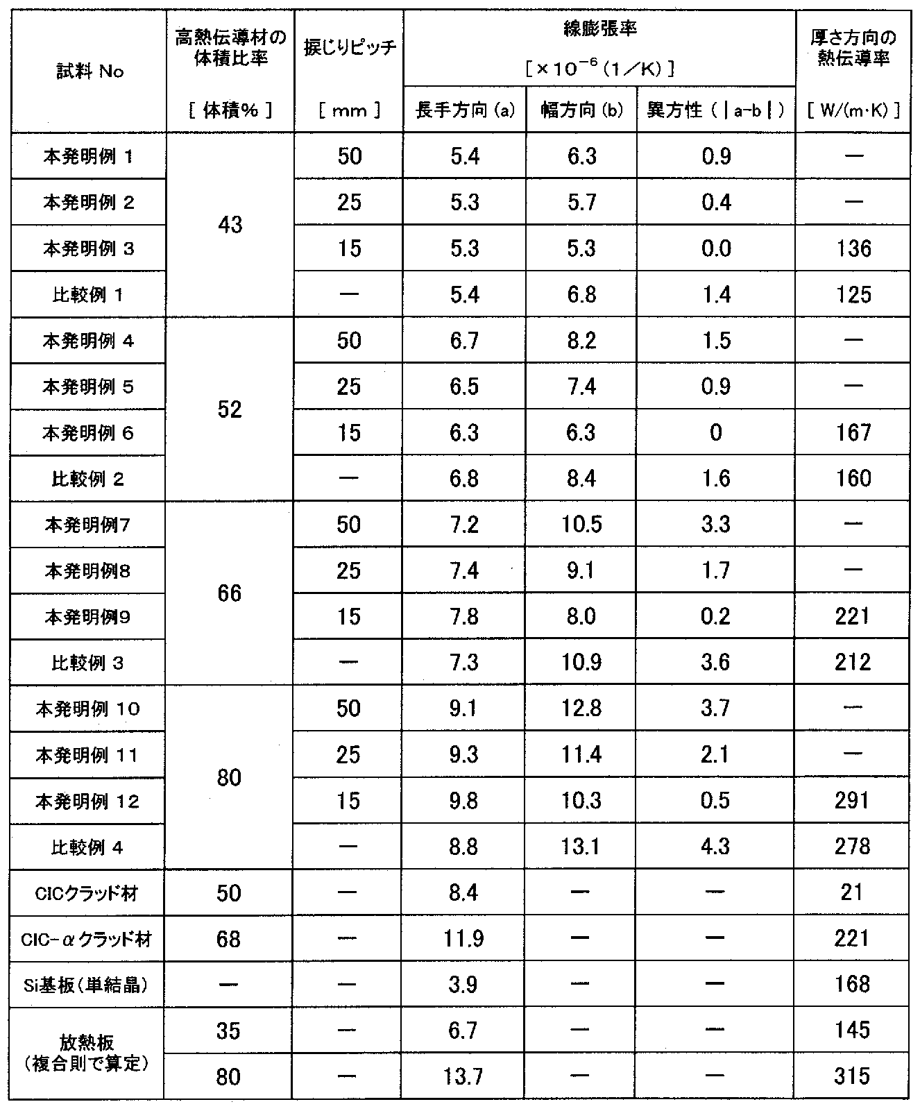
上記した製造方法により作製した、本発明例となる12種類の放熱板および比較例となる4種類の放熱板について、それぞれ、線膨張率および熱伝導率を求めた。線膨張率は、株式会社リガク製の熱膨張測定装置(型式:TMA8310)を用いて、25℃~170℃の範囲における、放熱板の長さ方向および幅方向の熱膨張量の測定を行ない、その測定結果から算出した。熱伝導率は、放熱板の厚さ方向の電気抵抗を測定することにより電気抵抗率ρを求め、Wiedemann-Frantzの法則に基づいて求めた。その結果を表1に示す。
ここで、特許文献1に開示され、従来例となるCICクラッド材およびCIC-αクラッド材について説明する。特許文献1の開示から、CICクラッド材は、高熱伝導材の体積比率が50体積%のときに長手方向の線膨張率が8.4×10⁻⁶(1/K)となり、放熱板として小さく好適な線膨張率を示す。しかし、CICクラッド材の高熱伝導材の体積率が50体積%のときの厚さ方向の熱伝導率は21W/(m・K)であり、放熱板としては小さく不満な熱伝導率を示す。また、同様に、低熱膨張材であるFeNi合金板にスリット孔を設けてFeNi層としたCIC-αクラッド材は、高熱伝導材の体積比率が68体積%のときに厚さ方向の熱伝導率が221W/(m・K)となり、放熱板として大きく好適な熱伝導率を示す。しかし、CIC-αクラッド材の高熱伝導材の体積比率が68体積%のときの長手方向の線膨張率は11.9×10-6(1/K)であり、放熱板としては大きくは不満な線膨張率を示す。これらの数値についても表1に併記する。
また、高熱伝導材と低熱膨張材とで単純に構成された放熱板を想定し、この放熱板の高熱伝導材の体積比率(VC)が35体積%の場合および80体積%の場合の熱伝導率および線膨張率を、単純な複合則によって計算した結果について説明する。なお、高熱伝導材は純Cuとし、熱伝導率(TC)を390W/(m・K)、線膨張率(KC)を16.8×10-6(1/K)とした。また、低熱膨張材は36アロイとし、熱伝導率(TF)を13W/(m・K)、線膨張率(KF)を1.2×10-6(1/K)とした。この場合、単純な複合則によれば、放熱板の熱伝導率はTc×VC+TF×(1-VC)により、線膨張率はKc×VC+KF×(1-VC)により、求めることができる。その結果、VCが35体積%の場合、放熱板の熱伝導率は約145W/(m・K)、線膨張率は約6.7×10-6(1/K)となった。また、VCが80体積%の場合、放熱板の熱伝導率は約315W/(m・K)、線膨張率は約13.7×10-6(1/K)となった。なお、例えば、半導体素子に多用されるSi基板(Si単結晶)の熱伝導率は約168W/(m・K)、線膨張率は約3.9×10-6(1/K)である。これらの数値についても表1に併記する。
(長手方向の線膨張率)
表1において、高熱伝導材の体積比率が小さくなると、本発明例および比較例の長手方向の線膨張率が小さくなる傾向が確認される。この傾向が生じるのは、低熱膨張材よりも熱伝導率が大きい高熱伝導材の体積割合が減少するからである。ここで、本発明例1~3の長手方向の線膨張率は、高熱伝導材の体積比率が大きい(43体積%)にも拘わらず、単純な複合則によって求めた高熱伝導材の体積比率が35体積%の線膨張率よりも小さくなった。
表1において、高熱伝導材の体積比率が小さくなると、本発明例および比較例の長手方向の線膨張率が小さくなる傾向が確認される。この傾向が生じるのは、低熱膨張材よりも熱伝導率が大きい高熱伝導材の体積割合が減少するからである。ここで、本発明例1~3の長手方向の線膨張率は、高熱伝導材の体積比率が大きい(43体積%)にも拘わらず、単純な複合則によって求めた高熱伝導材の体積比率が35体積%の線膨張率よりも小さくなった。
また、表1において、本発明例1~3と比較例1、本発明例4~6と比較例2、本発明例7~9と比較例3および本発明例10~12と比較例4との比較により、高熱伝導材の体積比率が43体積%、52体積%、66体積%および80体積%のそれぞれの場合において、長手方向の線膨張率は、本発明例と比較例との間に有意と考えるべき明確な差がないことが分かる。この結果から、長手方向の低熱膨張性は、捩じりの有無により有意と考えるべき明確な影響を受けないことが判明した。また、本発明例4~6の比較により、高熱伝導材の体積比率が52体積%の場合、捩じりピッチが小さくなると長手方向の線膨張率が小さくなる傾向が認められる。この傾向が生じるのは、捩じりピッチが小さくなることで相対的に長手方向における低熱膨張材の密度が大きくなるためと考えられる。また、本発明例7~9および本発明例10~12の比較により、高熱伝導材の体積比率が66体積%および80体積%の場合、捩じりピッチが小さくなると長手方向の線膨張率が大きくなる特異な傾向が認められる。この傾向が生じるのは、高熱伝導材の体積比率が大きいため、捩じりピッチが小さくなって相対的に長手方向における低熱膨張材の密度が大きくなる影響を受けにくいためと考えられる。
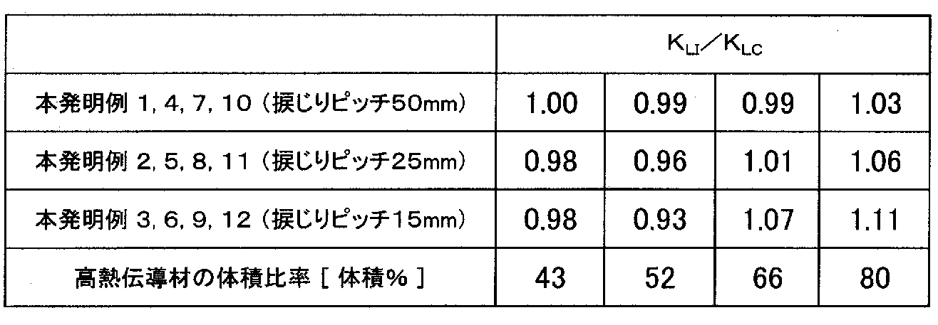
ここで、本発明例1~12の長手方向の線膨張率(KLI)をそれぞれに対応する比較例1~4の長手方向の線膨張率(KLC)で除して求めた値(KLI/KLC)を表2に示し、それに基づくグラフを図6に示す。図6において、高熱伝導材の体積比率を変化させたとき、KLI/KLCが1のラインを横切るのは、概ね40体積%から45体積%の間、および概ね60体積%から70体積%の間、と考えられる。長手方向の線膨張率が捩じりの影響を受けないと考えられるのはKLI/KLCが1のラインであり、捩じりの効果を得て長手方向の線膨張率が小さくなるのはKLI/KLCが1未満になる領域である。この観点において、本発明の放熱板の高熱伝導材の体積比率を、下限として、好ましくは40体積%以上、より好ましくは45体積%以上、より一層好ましくは50体積%以上とし、上限として、好ましくは70体積%以下、より好ましくは65体積%以下、より一層好ましくは60体積%以下とすれば、捩じりの効果を得て、長手方向の線膨張率をより小さくすることができる。なお、本発明の放熱板の高熱伝導材の体積比率の範囲は、上記した下限および上限を用途に応じて組み合わせることができる。
また、表1において、本発明例1~12とCICクラッド材との比較により、本発明例の長手方向の線膨張率は、CICクラッド材と同等またはCICクラッド材よりも小さいことが分かる。なお、この場合、本発明の放熱板の高熱伝導材の体積比率が80体積%未満(好ましくは75体積%以下、より好ましくは70体積%以下)に設定することにより、長手方向の線膨張率がCICクラッド材よりも確実に小さくなることが分かる。また、本発明例1~12とCIC-αクラッド材との比較により、本発明例の長手方向の線膨張率は、CIC-αクラッド材よりも明らかに小さいことが分かる。この結果から、本発明の放熱板は、高熱伝導材の内部の低熱膨張材(図5に示す複数の芯材3を参照)が特別な螺旋状の形態に配置されていることにより半導体素子の線膨張率に比較的近く、従来のCICクラッド材およびCIC-αクラッド材と比較して、長手方向の線膨張率が半導体素子(Si基板)の線膨張率により近いことが判明した。
(幅方向の線膨張率)
表1において、高熱伝導材の体積比率が大きくなると、本発明例および比較例の幅方向の線膨張率が大きくなる傾向が確認される。この傾向が生じるのは、低熱膨張材よりも熱伝導率が大きい高熱伝導材の体積割合が増加するからである。また、本発明例1~3と比較例1、本発明例4~6と比較例2、本発明例7~9と比較例3および本発明例10~12と比較例4との比較により、高熱伝導材の体積比率に関わらず本発明例と比較例との間に有意と考えるべき明確な差があり、本発明例の幅方向の線膨張率が比較例よりも小さいことが分かる。なお、この場合、本発明例1~3、4~6、7~9および10~12の比較により、捩じりピッチが小さくなると幅方向の線膨張率が小さくなる傾向が認められる。この傾向が生じるのは、捩じりピッチが小さくなることで相対的に低熱膨張材の密度が大きくなるからである。この結果から、本発明の放熱板は、高熱伝導材の内部の低熱膨張材(図5に示す複数の芯材3を参照)が特別な螺旋状の形態に配置されていることにより、捩じりのない比較例の放熱板と比較して、幅方向の線膨張率が小さくなることが判明した。
表1において、高熱伝導材の体積比率が大きくなると、本発明例および比較例の幅方向の線膨張率が大きくなる傾向が確認される。この傾向が生じるのは、低熱膨張材よりも熱伝導率が大きい高熱伝導材の体積割合が増加するからである。また、本発明例1~3と比較例1、本発明例4~6と比較例2、本発明例7~9と比較例3および本発明例10~12と比較例4との比較により、高熱伝導材の体積比率に関わらず本発明例と比較例との間に有意と考えるべき明確な差があり、本発明例の幅方向の線膨張率が比較例よりも小さいことが分かる。なお、この場合、本発明例1~3、4~6、7~9および10~12の比較により、捩じりピッチが小さくなると幅方向の線膨張率が小さくなる傾向が認められる。この傾向が生じるのは、捩じりピッチが小さくなることで相対的に低熱膨張材の密度が大きくなるからである。この結果から、本発明の放熱板は、高熱伝導材の内部の低熱膨張材(図5に示す複数の芯材3を参照)が特別な螺旋状の形態に配置されていることにより、捩じりのない比較例の放熱板と比較して、幅方向の線膨張率が小さくなることが判明した。
ここで、本発明例1~12の幅手方向の線膨張率(KWI)をそれぞれに対応する比較例1~4の幅方向の線膨張率(KWC)で除して求めた値(KWI/KWC)を表3に示し、それに基づくグラフを図7に示す。図7において、高熱伝導材の体積比率を変化させたとき、その全域で、KWI/KWCが1未満となった。また、捩じりピッチが小さいほど、幅方向の線膨張率が小さくなった。この結果から、高熱伝導材の体積比率に関わらず捩じりの効果が得られ、また、捩じりピッチが小さいほど多くの捩じりの効果が得られ、幅方向の線膨張率が小さくなることが判明した。この結果から、本発明の放熱板は、高熱伝導材の体積比率を35体積%以上80体積%以下とすることにより、捩じりの効果を得て、幅方向の線膨張率をより小さくすることができることが分かる。また、図7に示す線形近似線および2次近似線を考慮して高熱伝導材の体積比率の上限に着目すれば、好ましくは75体積%以下、より好ましくは70体積%以下、より一層好ましくは65体積%以下であることが分かる。

(線膨張の異方性)
表1に示す異方性は、長手方向の線膨張率(a)と幅方向の線膨張率(b)との差の絶対値(|a-b|)で評価したものである。表1において、本発明例および比較例の線膨張の異方性は、高熱伝導材の体積比率が小さくなると、長手方向および幅方向の線膨張率の変化傾向に基づいて、より抑制される傾向があることが分かる。また、本発明例1~3と比較例1、本発明例4~6と比較例2、本発明例7~9と比較例3および本発明例10~12と比較例4との比較により、高熱伝導材の体積比率に関わらず本発明例と比較例との間に有意と考えるべき明確な差があり、本発明例の線膨張の異方性が比較例よりも抑制されていることが分かる。なお、この場合、本発明例1~3、4~6、7~9および10~12の比較により、捩じりピッチが小さくなると線膨張の異方性がより抑制される傾向が認められる。この傾向が生じるのは、捩じりピッチが小さくなることで相対的に低熱膨張材の密度が大きくなるからである。この結果から、本発明の放熱板は、高熱伝導材の内部の低熱膨張材(図5に示す複数の芯材3を参照)が特別な螺旋状の形態に配置されていることにより熱膨張の異方性が比較的小さく、捩じりのない比較例の放熱板と比較して、線膨張の異方性が抑制されることが判明した。
表1に示す異方性は、長手方向の線膨張率(a)と幅方向の線膨張率(b)との差の絶対値(|a-b|)で評価したものである。表1において、本発明例および比較例の線膨張の異方性は、高熱伝導材の体積比率が小さくなると、長手方向および幅方向の線膨張率の変化傾向に基づいて、より抑制される傾向があることが分かる。また、本発明例1~3と比較例1、本発明例4~6と比較例2、本発明例7~9と比較例3および本発明例10~12と比較例4との比較により、高熱伝導材の体積比率に関わらず本発明例と比較例との間に有意と考えるべき明確な差があり、本発明例の線膨張の異方性が比較例よりも抑制されていることが分かる。なお、この場合、本発明例1~3、4~6、7~9および10~12の比較により、捩じりピッチが小さくなると線膨張の異方性がより抑制される傾向が認められる。この傾向が生じるのは、捩じりピッチが小さくなることで相対的に低熱膨張材の密度が大きくなるからである。この結果から、本発明の放熱板は、高熱伝導材の内部の低熱膨張材(図5に示す複数の芯材3を参照)が特別な螺旋状の形態に配置されていることにより熱膨張の異方性が比較的小さく、捩じりのない比較例の放熱板と比較して、線膨張の異方性が抑制されることが判明した。
(厚さ方向の熱伝導率)
表1において、高熱伝導材の体積比率が大きくなると、本発明例および比較例の厚さ方向の熱伝導率が大きくなる傾向が確認される。この傾向が生じるのは、低熱膨張材よりも熱伝導率が大きい高熱伝導材の体積割合が増加するからである。また、本発明例と比較例との比較により、高熱伝導材の体積比率に関わらず本発明例と比較例との間に有意と考えるべき明確な差があり、本発明例の厚さ方向の熱伝導率が比較例よりも大きいことが分かる。この結果から、本発明の放熱板は、高熱伝導材の内部の低熱膨張材(図5に示す複数の芯材3を参照)が特別な螺旋状の形態に配置されていることにより厚さ方向に比較的大きな熱伝導率を有し、捩じりのない比較例の放熱板と比較して、厚さ方向の熱伝導率が大きくなることが判明した。
表1において、高熱伝導材の体積比率が大きくなると、本発明例および比較例の厚さ方向の熱伝導率が大きくなる傾向が確認される。この傾向が生じるのは、低熱膨張材よりも熱伝導率が大きい高熱伝導材の体積割合が増加するからである。また、本発明例と比較例との比較により、高熱伝導材の体積比率に関わらず本発明例と比較例との間に有意と考えるべき明確な差があり、本発明例の厚さ方向の熱伝導率が比較例よりも大きいことが分かる。この結果から、本発明の放熱板は、高熱伝導材の内部の低熱膨張材(図5に示す複数の芯材3を参照)が特別な螺旋状の形態に配置されていることにより厚さ方向に比較的大きな熱伝導率を有し、捩じりのない比較例の放熱板と比較して、厚さ方向の熱伝導率が大きくなることが判明した。
ここで、本発明例3、6、9および12の厚さ方向の熱伝導率(TTI)をそれぞれに対応する比較例1~4の厚さ方向の熱伝導率(TTC)で除して求めた値(TTI/TTC)を表4に示し、それに基づくグラフを図8に示す。図8において、高熱伝導材の体積比率を変化させたとき、TTI/TTCが1のラインを横切るのは、概ね75体積%付近と考えられる。厚さ方向の熱伝導率が捩じりの影響を受けないと考えられるのはTTI/TTCが1のラインであり、捩じりの効果を得て厚さ方向の熱伝導率が大きくなるのはTTI/TTCが1を超える領域である。この観点において、本発明の放熱板の高熱伝導材の体積比率を、好ましくは35体積%以上75体積%以下とすることにより、捩じりの効果を得て、厚さ方向の熱伝導率を大きくすることができる。また、図8に示す3次近似線を考慮して高熱伝導材の体積比率の上限に着目すれば、好ましくは70体積%、より好ましくは65体積%であることが分かる。
また、表1において、本発明例とCICクラッド材との比較により、本発明例の厚さ方向の熱伝導率は、CICクラッド材よりも特段に大きいことが分かる。例えば、高熱伝導材の体積比率が66体積%の場合(本発明例9)の厚さ方向の熱伝導率は、CICクラッド材よりも約10倍大きく、43体積%の場合(本発明例3)でも6倍以上大きい。また、本発明例とCIC-αクラッド材との比較により、本発明例の厚さ方向の熱伝導率は、高熱伝導材の体積比率が66体積%の場合(本発明例9)にCIC-αクラッド材と同等となり、80体積%の場合(本発明例12)にはCIC-αクラッド材よりも明らかに大きくなることが分かる。なお、この場合、本発明の放熱板の高熱伝導材の体積比率が65体積%超(好ましくは70体積%以上)に設定することにより、厚さ方向の線膨張率がCIC-αクラッド材よりも確実に大きくなることが分かる。この結果から、本発明の放熱板は、高熱伝導材の内部の低熱膨張材(図5に示す複数の芯材3を参照)が特別な螺旋状の形態に配置されていることにより、従来のCIC-αクラッド材と比較して、厚さ方向により大きな線膨張率を有する場合があることが判明した。なお、この場合、本発明の放熱板の厚さ方向の熱伝導率が半導体素子(Si基板)の熱伝導率よりも大きくなるため、半導体素子からの抜熱および放熱に有効であることが分かる。
<18芯構造の放熱板>
本発明の放熱板の一実施形態となる、18芯構造の放熱板を作製した。18芯構造の放熱板の製造方法は、上記した7芯構造の場合と略同様である。具体的には、図4に示すように、高熱伝導材2として直径が62mmの純Cuからなる棒材と、低熱膨張材として36アロイからなる複数の芯材3を準備した。高熱伝導材2の長手方向の貫通孔は、高熱伝導材2の中心部を除く円形断面内に略均一配置される18か所に形成した。貫通穴の直径は9mmとした。芯材3の直径は8.6mmとした。高熱伝導材2(棒材)の18個の貫通孔のそれぞれに芯材3を装入し、高熱伝導材2(棒材)の長手方向の両端部にプラグを嵌め込み、図9に示す押出し用ビレットを作製した。この場合、押出し用ビレットの高熱伝導材2の体積比率は、約62体積%となる。
本発明の放熱板の一実施形態となる、18芯構造の放熱板を作製した。18芯構造の放熱板の製造方法は、上記した7芯構造の場合と略同様である。具体的には、図4に示すように、高熱伝導材2として直径が62mmの純Cuからなる棒材と、低熱膨張材として36アロイからなる複数の芯材3を準備した。高熱伝導材2の長手方向の貫通孔は、高熱伝導材2の中心部を除く円形断面内に略均一配置される18か所に形成した。貫通穴の直径は9mmとした。芯材3の直径は8.6mmとした。高熱伝導材2(棒材)の18個の貫通孔のそれぞれに芯材3を装入し、高熱伝導材2(棒材)の長手方向の両端部にプラグを嵌め込み、図9に示す押出し用ビレットを作製した。この場合、押出し用ビレットの高熱伝導材2の体積比率は、約62体積%となる。
続いて、押出し用ビレットを、約400℃に加熱した状態で、直径が22.5mmとなるように押出し加工した。続いて、伸線加工して細径化し、図10に示す横断面を有して成る、直径(線径)が6mmの複合線材5を作製した。そして、その複合線材5を2m毎の長さで切り分けた後、約700℃で1時間の保持条件で熱処理して軟化させた。ここまでが複合化工程となる。
次に、図5に示すように、複合線材5の捩じり加工を行った。具体的には、一端を万力で固定し、他端を3方チャックで固定した状態の複合線材5を、3方チャックを回転させて捩じることにより、捩回線材6を作製した。捩じりピッチPは、複合線材5の直径D(線径5mm)に対して、3.5倍のP=3.5D(21mm)とした。ここまでが捩回工程となる。
次に、捩回線材6を、常温(室温)で板状に圧延して、図11に示す幅方向断面(横断面)を有して成る、厚さ1.4mm×幅15mmの平角線材を作製した。この平角線材は本発明の放熱板の一実施形態である。この平角線材の外観を図12に示す。なお、図12では、高熱伝導材2の一部をエッチングによって除去して、低熱膨張材からなる芯材3を露出させ、その配置構成を示している。続いて、平角線材の幅方向の両端部を0.5mmずつ切断(スリッティング)し、圧延方向の長さが14mmとなるように切り出し、厚さ1.4mm×幅14mm×長さ14mmの放熱板1を作製した。ここまでが圧延工程となる。
上記した製造方法により作製した、本発明例となる放熱板の線膨張率および熱伝導率を求めた。熱膨張率は、株式会社リガク製の熱膨張測定装置(型式:TMA8310)を用いて、25℃~170℃の範囲における、放熱板の長さ方向および幅方向の熱膨張量の測定を行ない、その測定結果から算出した。熱伝導率は、放熱板の厚さ方向の電気抵抗を測定することにより電気抵抗率ρを求め、Wiedemann-Frantzの法則に基づいて求めた。その結果、18芯構造の放熱板の長手方向(圧延方向)の線膨張率は約8.5×10⁻⁶(1/K)、幅方向の線膨張率は約8.8×10-6(1/K)となった。この場合、線膨張の異方性は、約0.3×10-6(1/K)となる。また、18芯構造の放熱板の厚さ方向の熱伝導率は、約260W/(m・K)となった。
これにより、18芯構造の放熱板は熱膨張の異方性が小さく抑制されており、長手方向の線膨張率が、表1に示すCIC-αクラッド材(高熱伝導材の体積比率が68体積%)よりも約30%小さく、半導体素子に多用される例えばSi基板(Si単結晶)の線膨張率に近くなることが確認された。また、18芯構造の放熱板は、厚さ方向の熱伝導率が、表1に示すCIC-αクラッド材(高熱伝導材の体積比率が68体積%)よりも約18%大きく、半導体素子に多用される例えばSi基板(Si単結晶)の熱伝導率よりも約55%大きくなることが確認された。この結果から、本発明の放熱板は、高熱伝導材の内部の低熱膨張材(図5に示す複数の芯材3を参照)が特別な螺旋状の形態に配置されていることにより、線膨張の異方性が緩和され、長手方向の線膨張率が従来のCIC-αクラッド材よりも半導体素子(Si基板)に近づき、厚さ方向の熱伝導率が大きくなるため、半導体素子からの抜熱および放熱に有効であることが判明した。
1.放熱板
2.高熱伝導材
3.芯材
4.中心芯材
5.複合線材
6.捩回線材
7.絶縁基板
8.半導体素子
2.高熱伝導材
3.芯材
4.中心芯材
5.複合線材
6.捩回線材
7.絶縁基板
8.半導体素子
Claims (6)
- 低熱膨張材からなる複数の芯材が、高熱伝導材の長手方向、幅方向および厚さ方向において互いに非接触で、長手方向に螺旋状に装入されている放熱板。
- 前記高熱伝導材は、CuまたはCu合金からなる請求項1に記載の放熱板。
- 前記低熱膨張材は、FeNi系合金からなる請求項1または請求項2に記載の放熱板。
- 前記高熱伝導材の体積比率が35体積%以上80体積%以下である請求項1ないし請求項3のいずれか1項に記載の放熱板。
- 円形断面を有する高熱伝導材からなる線材の長手方向に低熱膨張材からなる複数の芯材を装入し、前記線材の長手方向、幅方向および厚さ方向において、前記複数の芯材が互いに非接触となる複合線材を得る複合化工程と、
前記複合線材の長手方向に捩じり加工を施して捩回線材を得る捩回工程と、
前記捩回線材を板状に圧延する圧延工程を有する放熱板の製造方法。 - 前記捩回線材の捩じりピッチPを、前記複合線材の直径Dに対して1.5D≦P≦5.0Dの範囲にする請求項5に記載の放熱板の製造方法。
Priority Applications (1)
| Application Number | Priority Date | Filing Date | Title |
|---|---|---|---|
| JP2020548332A JP7248032B2 (ja) | 2018-09-19 | 2019-09-06 | 放熱板およびその製造方法 |
Applications Claiming Priority (2)
| Application Number | Priority Date | Filing Date | Title |
|---|---|---|---|
| JP2018174954 | 2018-09-19 | ||
| JP2018-174954 | 2018-09-19 |
Publications (1)
| Publication Number | Publication Date |
|---|---|
| WO2020059541A1 true WO2020059541A1 (ja) | 2020-03-26 |
Family
ID=69887313
Family Applications (1)
| Application Number | Title | Priority Date | Filing Date |
|---|---|---|---|
| PCT/JP2019/035193 Ceased WO2020059541A1 (ja) | 2018-09-19 | 2019-09-06 | 放熱板およびその製造方法 |
Country Status (2)
| Country | Link |
|---|---|
| JP (1) | JP7248032B2 (ja) |
| WO (1) | WO2020059541A1 (ja) |
Cited By (1)
| Publication number | Priority date | Publication date | Assignee | Title |
|---|---|---|---|---|
| KR20230137507A (ko) * | 2022-03-21 | 2023-10-05 | 주식회사 세원텍 | 향상된 방열성능을 갖는 방열성형체의 제조방법, 및 이를 이용하여 제조된 방열성형체 |
Citations (2)
| Publication number | Priority date | Publication date | Assignee | Title |
|---|---|---|---|---|
| JPH07249717A (ja) * | 1994-03-08 | 1995-09-26 | Toho Kinzoku Kk | 放熱基板材料 |
| US6326685B1 (en) * | 1998-05-04 | 2001-12-04 | Agere Systems Guardian Corp. | Low thermal expansion composite comprising bodies of negative CTE material disposed within a positive CTE matrix |
-
2019
- 2019-09-06 JP JP2020548332A patent/JP7248032B2/ja active Active
- 2019-09-06 WO PCT/JP2019/035193 patent/WO2020059541A1/ja not_active Ceased
Patent Citations (2)
| Publication number | Priority date | Publication date | Assignee | Title |
|---|---|---|---|---|
| JPH07249717A (ja) * | 1994-03-08 | 1995-09-26 | Toho Kinzoku Kk | 放熱基板材料 |
| US6326685B1 (en) * | 1998-05-04 | 2001-12-04 | Agere Systems Guardian Corp. | Low thermal expansion composite comprising bodies of negative CTE material disposed within a positive CTE matrix |
Cited By (2)
| Publication number | Priority date | Publication date | Assignee | Title |
|---|---|---|---|---|
| KR20230137507A (ko) * | 2022-03-21 | 2023-10-05 | 주식회사 세원텍 | 향상된 방열성능을 갖는 방열성형체의 제조방법, 및 이를 이용하여 제조된 방열성형체 |
| KR102820021B1 (ko) | 2022-03-21 | 2025-06-16 | 김와룡 | 향상된 방열성능을 갖는 방열성형체의 제조방법, 및 이를 이용하여 제조된 방열성형체 |
Also Published As
| Publication number | Publication date |
|---|---|
| JPWO2020059541A1 (ja) | 2021-08-30 |
| JP7248032B2 (ja) | 2023-03-29 |
Similar Documents
| Publication | Publication Date | Title |
|---|---|---|
| JP5847787B2 (ja) | 導電性及び応力緩和特性に優れる銅合金板 | |
| US9397064B2 (en) | Aluminum alloy wire for bonding applications | |
| KR102194267B1 (ko) | 저항 합금, 그로부터 제조된 구성 요소 및 이의 제조방법 | |
| US6326685B1 (en) | Low thermal expansion composite comprising bodies of negative CTE material disposed within a positive CTE matrix | |
| JP6719316B2 (ja) | 放熱部材用銅合金板材およびその製造方法 | |
| JP4168077B2 (ja) | 酸化膜密着性に優れた電気電子部品用銅合金板 | |
| KR20090101833A (ko) | 도금된 평판 도체 및 이것을 이용한 가요성 평판 케이블 | |
| JP6446011B2 (ja) | 放熱部品用銅合金板及び放熱部品 | |
| JP6050738B2 (ja) | 導電性、成形加工性および応力緩和特性に優れる銅合金板 | |
| CN106029929A (zh) | 轧制铜箔、轧制铜箔的制造方法、柔性带状电缆、柔性带状电缆的制造方法 | |
| JP5467163B1 (ja) | 銅合金板、それを備える放熱用電子部品および、銅合金板の製造方法 | |
| JP2018162518A (ja) | ベーパーチャンバー用銅合金板及びベーパーチャンバー | |
| JP6328380B2 (ja) | 導電性及び曲げたわみ係数に優れる銅合金板 | |
| WO2015075990A1 (ja) | 銅合金板、並びに、それを備える大電流用電子部品及び放熱用電子部品 | |
| JP7248032B2 (ja) | 放熱板およびその製造方法 | |
| JP2019091916A (ja) | ボンディング用途のための厚い銅ワイヤを製造するための方法 | |
| JP6257912B2 (ja) | 導電性及び応力緩和特性に優れる銅合金板 | |
| WO2016111206A1 (ja) | 放熱基板 | |
| CN120519735A (zh) | 一种耐高温软化性能优异的铜合金及其制备方法与应用 | |
| JP2007113093A (ja) | 高強度高導電性耐熱銅合金及びその製造方法 | |
| WO2019187767A1 (ja) | 絶縁基板及びその製造方法 | |
| WO2014041865A1 (ja) | 導電性及び応力緩和特性に優れる銅合金板 | |
| JP4988243B2 (ja) | プリント配線基板 | |
| JP5352750B1 (ja) | 導電性及び曲げたわみ係数に優れる銅合金板 | |
| JP4617884B2 (ja) | 接続用リード線およびその製造方法 |
Legal Events
| Date | Code | Title | Description |
|---|---|---|---|
| 121 | Ep: the epo has been informed by wipo that ep was designated in this application |
Ref document number: 19863095 Country of ref document: EP Kind code of ref document: A1 |
|
| ENP | Entry into the national phase |
Ref document number: 2020548332 Country of ref document: JP Kind code of ref document: A |
|
| NENP | Non-entry into the national phase |
Ref country code: DE |
|
| 122 | Ep: pct application non-entry in european phase |
Ref document number: 19863095 Country of ref document: EP Kind code of ref document: A1 |