WO2020054687A1 - Method for treating organic wastewater, and device for treating organic wastewater - Google Patents
Method for treating organic wastewater, and device for treating organic wastewater Download PDFInfo
- Publication number
- WO2020054687A1 WO2020054687A1 PCT/JP2019/035456 JP2019035456W WO2020054687A1 WO 2020054687 A1 WO2020054687 A1 WO 2020054687A1 JP 2019035456 W JP2019035456 W JP 2019035456W WO 2020054687 A1 WO2020054687 A1 WO 2020054687A1
- Authority
- WO
- WIPO (PCT)
- Prior art keywords
- tank
- organic wastewater
- biological treatment
- activated sludge
- anaerobic
- Prior art date
Links
Images


Classifications
-
- C—CHEMISTRY; METALLURGY
- C02—TREATMENT OF WATER, WASTE WATER, SEWAGE, OR SLUDGE
- C02F—TREATMENT OF WATER, WASTE WATER, SEWAGE, OR SLUDGE
- C02F3/00—Biological treatment of water, waste water, or sewage
- C02F3/02—Aerobic processes
- C02F3/12—Activated sludge processes
- C02F3/1236—Particular type of activated sludge installations
- C02F3/1268—Membrane bioreactor systems
- C02F3/1273—Submerged membrane bioreactors
-
- C—CHEMISTRY; METALLURGY
- C02—TREATMENT OF WATER, WASTE WATER, SEWAGE, OR SLUDGE
- C02F—TREATMENT OF WATER, WASTE WATER, SEWAGE, OR SLUDGE
- C02F3/00—Biological treatment of water, waste water, or sewage
- C02F3/02—Aerobic processes
- C02F3/12—Activated sludge processes
- C02F3/1205—Particular type of activated sludge processes
- C02F3/121—Multistep treatment
-
- C—CHEMISTRY; METALLURGY
- C02—TREATMENT OF WATER, WASTE WATER, SEWAGE, OR SLUDGE
- C02F—TREATMENT OF WATER, WASTE WATER, SEWAGE, OR SLUDGE
- C02F3/00—Biological treatment of water, waste water, or sewage
- C02F3/30—Aerobic and anaerobic processes
- C02F3/302—Nitrification and denitrification treatment
-
- C—CHEMISTRY; METALLURGY
- C02—TREATMENT OF WATER, WASTE WATER, SEWAGE, OR SLUDGE
- C02F—TREATMENT OF WATER, WASTE WATER, SEWAGE, OR SLUDGE
- C02F3/00—Biological treatment of water, waste water, or sewage
- C02F3/30—Aerobic and anaerobic processes
- C02F3/308—Biological phosphorus removal
-
- C—CHEMISTRY; METALLURGY
- C02—TREATMENT OF WATER, WASTE WATER, SEWAGE, OR SLUDGE
- C02F—TREATMENT OF WATER, WASTE WATER, SEWAGE, OR SLUDGE
- C02F2203/00—Apparatus and plants for the biological treatment of water, waste water or sewage
- C02F2203/006—Apparatus and plants for the biological treatment of water, waste water or sewage details of construction, e.g. specially adapted seals, modules, connections
-
- C—CHEMISTRY; METALLURGY
- C02—TREATMENT OF WATER, WASTE WATER, SEWAGE, OR SLUDGE
- C02F—TREATMENT OF WATER, WASTE WATER, SEWAGE, OR SLUDGE
- C02F2301/00—General aspects of water treatment
- C02F2301/04—Flow arrangements
- C02F2301/046—Recirculation with an external loop
-
- C—CHEMISTRY; METALLURGY
- C02—TREATMENT OF WATER, WASTE WATER, SEWAGE, OR SLUDGE
- C02F—TREATMENT OF WATER, WASTE WATER, SEWAGE, OR SLUDGE
- C02F2301/00—General aspects of water treatment
- C02F2301/08—Multistage treatments, e.g. repetition of the same process step under different conditions
-
- Y—GENERAL TAGGING OF NEW TECHNOLOGICAL DEVELOPMENTS; GENERAL TAGGING OF CROSS-SECTIONAL TECHNOLOGIES SPANNING OVER SEVERAL SECTIONS OF THE IPC; TECHNICAL SUBJECTS COVERED BY FORMER USPC CROSS-REFERENCE ART COLLECTIONS [XRACs] AND DIGESTS
- Y02—TECHNOLOGIES OR APPLICATIONS FOR MITIGATION OR ADAPTATION AGAINST CLIMATE CHANGE
- Y02W—CLIMATE CHANGE MITIGATION TECHNOLOGIES RELATED TO WASTEWATER TREATMENT OR WASTE MANAGEMENT
- Y02W10/00—Technologies for wastewater treatment
- Y02W10/10—Biological treatment of water, waste water, or sewage
Definitions
- the present invention relates to an organic wastewater treatment method and an organic wastewater treatment device.
- an organic wastewater treatment method for biologically treating organic wastewater containing nitrogen and phosphorus using activated sludge an anaerobic tank, an anoxic tank, and an aerobic tank are arranged in this order, and the sludge in the aerobic tank is anaerobic.
- a circulating anaerobic and aerobic method (A2O method (also referred to as UCT method)) for circulating and supplying a tank or an anoxic tank is widely used.
- UCT method also referred to as UCT method
- MBR method such as UCT-MBR in which a membrane separation device is immersed and arranged in an aerobic tank instead of a settling tank for solid-liquid separation has attracted attention.
- Patent Literature 1 discloses a compact nitrogen-containing wastewater treatment facility with a nitrogen removal rate of 90% or more.
- a plurality of anaerobic tanks and aerobic tanks are alternately connected in series in the order of an anaerobic tank and an aerobic tank.
- a supply path for supplying the liquid is provided.
- the last aerobic tank is equipped with a dip-type separator to separate the activated sludge to obtain a treatment liquid, and a path for returning the activated sludge from the last aerobic tank to the foremost anaerobic tank is provided.
- the anaerobic tank of the processing equipment functions as an oxygen-free tank.
- Patent Literature 2 discloses a membrane separation device that performs advanced processing only in one processing tank.
- the membrane separation device is provided with an endless treatment tank in which the water to be treated is biologically treated and in which the swirling flow of the to-be-processed water is formed, and at an interval in the flow direction of the swirling flow.
- the raw water tank is provided inside the swirl flow, and a supply unit that supplies the water to be treated from the raw water tank to the treatment tank performs supply in multiple stages in the flow direction of the swirl flow. Have been.
- An object of the present invention is to provide an organic wastewater treatment method and an organic wastewater treatment apparatus capable of efficiently denitrifying and dephosphorizing organic wastewater containing nitrogen and phosphorus without increasing the cost. The point is to provide.
- the entire amount of the organic acid contained in the organic wastewater can be used for discharging phosphorus in the anaerobic tank, so that high dephosphorization performance can be obtained without using a coagulant.
- the membrane separation device since the stoppage or the operation of the membrane separation device can be switched and adjusted for each biological treatment unit based on the degree of the load of the nitrification / denitrification treatment on the organic wastewater, the membrane separation can be performed while ensuring high denitrification performance.
- the power required for the aeration device provided in the device can be optimized, and the operating cost can be reduced.
- by enabling the chemical cleaning of the membrane to be performed independently for each aerobic tank an increase in the phosphorus concentration in the treated water after the cleaning can be suppressed.
- a first characteristic configuration of the wastewater treatment apparatus is an organic wastewater treatment apparatus for biologically treating organic wastewater containing nitrogen and phosphorus in activated sludge, which is disposed on an upstream side along a flow of the organic wastewater.
- An anoxic tank and an aerobic tank disposed downstream of the membrane separation device immersed in activated sludge and a pair of biological treatment units, and a biological treatment tank that connects a plurality of biological treatment units in series.
- An anaerobic tank for anaerobic treatment of organic wastewater a sludge return route for returning activated sludge from an aerobic tank provided at the most downstream to an oxygen-free tank provided at the most upstream, and A raw water supply path for dividing and supplying the oxygen-free tank of each biological treatment unit from the tank, and a treated water supply path for delivering the membrane permeate as treated water from the membrane separation device of each biological treatment unit.
- the organic wastewater containing nitrogen and phosphorus is introduced into the anaerobic tank and subjected to anaerobic treatment to discharge phosphorus from the activated sludge, and then divided and supplied to the anoxic tanks constituting each biological treatment unit via the raw water supply path Is done.
- the organic wastewater divided and supplied to the anoxic tank flows down from the anoxic tank to the aerobic tank from upstream to downstream in each biological treatment unit together with activated sludge, and denitrification and nitrification are repeated.
- the denitrification process is efficiently repeated by returning from the aerobic tank installed at the most downstream to the anoxic tank installed at the most upstream via the sludge return path, and immersed in each aerobic tank Solid-liquid separation is performed by the disposed membrane separation device, and the treated water is taken out.
- a second characteristic configuration of the wastewater treatment device is that the wastewater treatment apparatus includes an anaerobic tank return path for returning activated sludge from the anoxic tank to the anaerobic tank in addition to the above-described first characteristic configuration.
- the biological treatment tank has an annular shape by alternately arranging the anoxic tank and the aerobic tank. None, the anaerobic tank is located inside the ring.
- the fourth characteristic configuration of the wastewater treatment device is such that, in addition to any of the first to third characteristic configurations described above, each anoxic tank and each aerobic tank are vertically arranged via a boundary wall.
- the aerobic tank is disposed above the boundary wall, and the anoxic tank is disposed below the aerobic tank.
- the aerobic tank is located above the anoxic tank, the installation area can be greatly reduced and a compact organic wastewater treatment device can be realized. Moreover, as a result of the anoxic tank being installed below the aerobic tank with the boundary wall interposed therebetween, there is no need to provide a special cover for shutting off outside air in the anoxic tank, and equipment costs are reduced.
- an organic wastewater treatment method and an organic wastewater treatment method capable of efficiently denitrifying and dephosphorizing organic wastewater containing nitrogen and phosphorus without increasing the cost. It has become possible to provide a wastewater treatment apparatus.
- FIG. 1 is a schematic explanatory view of a wastewater treatment apparatus according to the present invention corresponding to organic wastewater containing nitrogen and phosphorus.
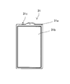
- FIG. 2 is an explanatory diagram of a membrane element provided in the membrane separation device.
- FIG. 3A is an explanatory plan view showing one embodiment of the wastewater treatment apparatus according to the present invention.
- FIG. 3B is an explanatory front view illustrating one embodiment of the wastewater treatment apparatus according to the present invention.
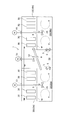
- FIG. 4A is a bottom view illustrating another embodiment of the wastewater treatment method according to the present invention.
- FIG. 4B is an explanatory view showing a cross section taken along line AA of FIG. 4A and showing another embodiment of the wastewater treatment method according to the present invention.
- FIG. 5A is an explanatory plan view showing another embodiment of the wastewater treatment method according to the present invention.
- FIG. 5B is a diagram illustrating a cross section taken along line BB of FIG. 5A and illustrating another embodiment of the wastewater treatment method according to the present invention.
- the wastewater treatment apparatus according to the present invention is an organic wastewater treatment apparatus for biologically treating organic wastewater containing nitrogen and phosphorus in activated sludge.
- FIG. 1 shows the concept of the organic wastewater treatment device.
- the wastewater treatment apparatus 1 includes an oxygen-free tank 10 (10a, 10b, 10c, 10d) disposed on the upstream side along the flow of organic wastewater containing nitrogen and phosphorus (hereinafter, also referred to as “raw water”).
- An aerobic tank 20 (20a, 20b, 20c, 20d) disposed downstream is provided as a pair of biological treatment units, and a biological treatment tank 2 for connecting a plurality of biological treatment units in series is provided.
- a membrane separation device 30 is immersed and arranged in activated sludge, and is arranged at the most upstream from the aerobic tank 20d arranged at the most downstream.
- a sludge return path 3 for returning activated sludge to the anoxic tank 10a is provided.
- the wastewater treatment apparatus 1 further divides the organic wastewater from the anaerobic tank 50 into the oxygen-free tank 20 of each biological treatment unit by anaerobic treatment of the organic wastewater introduced through the raw water conduit 4.
- a raw water supply path 5 (5a, 5b, 5c, 5d) and an anaerobic tank return path 6 (6a, 6b, 6c, 6d) for returning activated sludge from the anoxic tank 10 to the anaerobic tank 50;
- a treated water delivery path 7 for delivering the permeated liquid as treated water from the membrane separation device 30 of the biological treatment unit.
- the organic acid contained in the organic wastewater as raw water is used for discharging phosphorus in the anaerobic tank 50, so that high phosphorus removal performance can be obtained without using a coagulant.
- the discharge of the phosphorus from the activated sludge returned through the anaerobic tank return path 6 becomes remarkable due to the organic acid contained in the organic wastewater charged into the anaerobic tank 50, and thereafter, the phosphorus flows down to the aerobic tank 20. Excessive intake of phosphorus by the activated sludge is promoted, and phosphorus can be efficiently removed without using a flocculant for precipitating as insoluble phosphate.
- nitrate nitrogen obtained by nitrification of ammonia nitrogen in the aerobic tank 20 is reduced to nitrogen in the anoxic tank 10, so that effective denitrification treatment can be realized.
- FIGS. 3A and 3B show an example of a wastewater treatment apparatus 1 in which a biological treatment tank 2 is formed in a ring shape as a whole by arranging an anoxic tank 10 and an aerobic tank 20 alternately as a pair of biological treatment units. Have been.
- a biological treatment tank 2 is formed in a ring shape as a whole by arranging an anoxic tank 10 and an aerobic tank 20 alternately as a pair of biological treatment units. Have been.
- one anaerobic tank 50 is provided in the biological treatment tank 2, and the anaerobic tank 50 and each of the anoxic tanks 10 are individually connected by a raw water supply path 5 and an anaerobic tank return path 6.
- the biological treatment tank 2 is configured in which four pairs of biological treatment units are arranged in series along the flow of the organic wastewater and in an endless manner.
- the number of biological treatment units may be plural, and is not limited to four pairs as in this example.
- a plurality of biological treatment units can be configured by dividing the single biological treatment tank 2 into a plurality of regions, and a plurality of individual anoxic tanks 10 and aerobic tanks 20 are paired along the flow of organic wastewater.
- the biological treatment tank 2 can be configured by arranging them.
- Organic wastewater which is raw water
- the anaerobic tank 50 performs a process of releasing phosphorus from activated sludge, which is an anaerobic treatment, and the anaerobic tank 50 supplies the raw water supply path 5.
- the raw water is supplied to each of the oxygen-free tanks 10 together with the activated sludge in approximately equal amounts via the.
- the raw water flows into the downstream aerobic tank 20 together with the activated sludge, and the nitrification treatment, which is the aerobic treatment, is performed.
- the membrane separation device 30 is immersed in each aerobic tank 20, and an auxiliary aeration device 40 for aerobic treatment is installed in the vicinity thereof. A part of the activated sludge is returned from each of the oxygen-free tanks 10 to the anaerobic tank 50 via the anaerobic tank return path 6, and phosphorus is released in the anaerobic tank 50.
- An air lift pump AP is installed in the anoxic tank 10 (10a) on the most upstream side, and organic wastewater and activated sludge are discharged downstream along with activated sludge by an ascending flow in an air lift pipe generated by bubbles supplied from the blower B via a valve V10. Is sent to the aerobic tank 20 (20a), and thereafter, the anoxic tank 10 (10b), the aerobic tank 20 (20b), the anoxic tank 10 (10c), the aerobic tank 20 (20c), the anoxic tank 10 (10d), it flows naturally in the order of the aerobic tank 20 (20d).
- the air lift pump AP Since the air lift pump AP is provided in the anoxic tank 10, the amount of dissolved oxygen DO in the anoxic tank 10 can be reduced as compared with the case where the air lift pump AP is provided in the aerobic tank 20 and the liquid is sent to the anoxic tank 10. There is no increase.
- four pairs of biological treatment units are disposed in an endless manner along the flow of the organic wastewater, and the aerobic tank 20 (20d) disposed at the most downstream and the non-terminal disposed at the most upstream.
- the oxygen tank 10 (10a) is arranged adjacent to the partition wall, and the sludge return path 3 for returning the activated sludge of the most downstream aerobic tank 20 (20d) to the uppermost oxygen-free tank 10 (10a) is the partition wall. It is formed in a part of.
- a partition W1 is formed between the anaerobic tank 10 and the aerobic tank 20, and an organic wastewater containing activated sludge from the anaerobic tank 10 overflows into the aerobic tank 20 at a part of the upper end side of the partition W1.
- a notch 11 (see FIG. 3B) is provided.
- a partition W2 is formed between the aerobic tank 20 and the anoxic tank 10, and an outflow portion 21 for organic wastewater containing activated sludge is provided at a position corresponding to the vicinity of the bottom of the membrane separation device 30 in the vertical direction of the partition W2. Have been.
- the upper end of the opening serving as the outflow portion 21 is submerged, and is provided at a position 30 cm or less from the water surface of the aerobic tank 20.
- the flow rate of the activated sludge from the outlet 21 is 0.5 m / sec. It is set as follows.
- the outflow part 21 formed in the most downstream aerobic tank 20 (20d) becomes the above-mentioned sludge return path.
- an arrow indicated by a two-dot chain line indicates that activated sludge flows in each biological treatment unit to form a circulating flow.
- the membrane separation device 30 includes a plurality of membrane elements 31 and an aeration device 32 installed below the membrane elements 31 (see FIG. 3B).
- the plurality of membrane elements 31 are arranged and accommodated in the casing in a two-tiered manner at regular intervals so that each membrane surface has a vertical posture.
- the membrane element 31 has a structure in which separation membranes 31b are arranged on both front and back surfaces of a resin-made membrane support 31a having a water collecting pipe 31c at an upper portion.
- the separation membrane 31b is constituted by a microfiltration membrane having a porous organic polymer membrane on the surface of a nonwoven fabric and having a nominal pore size of about 0.4 ⁇ m.
- the type of the separation membrane 31b and the membrane element 31 are not limited to the above-described embodiments, and any type of separation membrane and any type of membrane element (hollow fiber membrane element, tubular membrane element, monolith membrane element, etc.) Can be used.
- the treated water that has passed through the separation membrane 31b flows into the water collecting pipe 31c along a groove formed in the membrane support 31a, and as shown in FIGS. 3A and 3B, air flows from the water collecting pipe 31c via the header pipe 34.
- the water flows into the separation tank 35 and is collected in a treated water tank 37 via a liquid feed pipe 36 connected to the air separation tank 35.
- Each header pipe 34 is provided with a flow control valve V5, V6, V7, V8, respectively, and the liquid feed pipe 36 is provided with a suction pump P.
- the amount of permeated water from each membrane separator 30 is adjusted by adjusting the pressure by the suction pump P and adjusting the opening of the valves V5, V6, V7, and V8.
- a pressure sensor Pm is provided between the air separation tank 35 and the suction pump P to detect the transmembrane pressure of the membrane separation device 30.
- reference numeral M denotes a motor for adjusting the valve opening.
- a path that flows from the water collecting pipe 31c into the air separation tank 35 via the header pipe 34 and is collected in the processing water tank 37 through the liquid sending pipe 36 connected to the air separation tank 35 is a processing water delivery path 7 Become.
- each sub-blower Ts are branched and connected to the main blower Tm connected to the blower B, and each aeration device 32 is connected to each sub-blower Ts.
- Valves V1, V2,... For restricting the flow rate are provided in the sub-blower Ts corresponding to the membrane separation tank 30 installed in each aerobic tank 20, respectively, and the aeration amount and the stop and start of the aeration can be controlled. Is configured.
- the organic wastewater is aerated with the activated sludge in the aerobic tank 20 by the auxiliary diffuser 40, the organic matter is decomposed, and the ammonia nitrogen is nitrified into nitrate nitrogen, and the activated sludge excessively ingests phosphorus, Part of the liquid is solid-liquid separated by the membrane separation device 30 as treated water.
- the inflow of raw water per unit time is Q
- the inflow of raw water into each anoxic tank 10 is Q / 4
- the total amount of treated water of Q permeate is withdrawn from each membrane separation device 30 and is the most downstream.
- the organic wastewater treatment apparatus 1 includes a flowmeter for measuring the inflow amount of organic wastewater, a liquid level meter for measuring the tank level, a pressure sensor for measuring the transmembrane pressure of each membrane separator, and a treatment water tank 37.
- a plurality of measuring devices such as a measuring instrument S for measuring the NH 3 -N concentration in the treated water are provided.
- a control unit 60 which serves as a control device for controlling the operation of the organic wastewater treatment device 1 based on the values measured by the measurement devices.
- the control unit 60 is configured by a control panel including a computer having an arithmetic circuit, an input circuit, an output circuit, and the like.
- the control unit 60 is a measuring device for measuring the degree of inflow of raw water measured by the measuring devices, the water level of the biological treatment tank 2, the value of each pressure sensor Pm, and the total nitrogen (TN) concentration provided in the treatment water tank 37. While monitoring the value of S and the like, each membrane separation device 30 is repeatedly operated in two modes of a filtration operation state and a relaxation operation state.
- the filtration operation state refers to a state in which the membrane permeated water is withdrawn as treated water from the water collection pipe 31c while performing aeration by the aeration device 32
- the relaxation operation state refers to a state in which a valve provided in the header pipe 34 is closed or a suction pump P is used. Is a state in which the surface of the separation membrane 31b is cleaned by an upward flow generated by bubbles by performing aeration by the aeration device 32 in a state where is stopped.
- the control unit 60 repeats the filtration operation for a first predetermined time (for example, 9 minutes) and the relaxation operation for a second predetermined time (for example, 1 minute).
- the membrane separation of the aerobic tank 20 is assumed. Even if the apparatus 30 is stopped and the activated sludge is not stirred, the activated sludge is surely sent to the downstream oxygen-free tank.
- the dissolved oxygen concentration DO is lower near the bottom of the membrane separation device 30 than near the liquid surface, an increase in the dissolved oxygen concentration in the downstream anoxic tank 10 can be suppressed.
- the flow rate of activated sludge is 0.5 m / sec. If it is set as follows, it is possible to suppress the occurrence of a water level difference between the aerobic tank and the anoxic tank due to the inflow of the activated sludge, and to achieve uniform aeration of the activated sludge in the aerobic tank.
- the activated sludge flow rate was 0.5 m / sec.
- the notch 11 is set as follows, and the amount of air supplied to the air lift pump AP is adjusted.
- the biological treatment tank 2 is configured as a whole by alternately arranging the anoxic tank 10 and the aerobic tank 20 as a pair of biological treatment units, and the anaerobic tank 50 is disposed inside the ring. Have been.
- Each raw water supply path 5 is provided with an air lift pump, is configured so that activated sludge is supplied to the oxygen-free tank 10 by the air lift pump, and is formed in the liquid by a partition wall between the anaerobic tank 50 and the oxygen-free tank 20.
- Each anaerobic tank return path 6 is constituted by the opening.
- a groove-shaped ceiling slab 51 is formed in the anaerobic tank 50 at a position lower than the liquid level of the aerobic tank 10 and the anoxic tank 20, and the groove-shaped space is shown in FIG. 3A.
- a pipe pit 52 in which such a header pipe 34, an air separation tank 35, valves V5, V6, V7, V8 for adjusting the flow rate, a liquid feed pipe 36, a suction pump P and the like are provided.
- a cylindrical portion 53 is formed on the ceiling slab 51, and a stirring blade 54 for stirring raw water and activated sludge inside the anaerobic tank 50 is detachably attached via the cylindrical portion 53.
- reference numeral M denotes a motor that drives the stirring blade 54.
- the tubular portion 53 is covered so that outside air does not flow into the anaerobic tank 50.
- the configuration other than the anaerobic tank 50 is the same as the configuration described with reference to FIGS. 3A and 3B.
- the sludge return path 3 can be formed to be the shortest by arranging the plurality of biological treatment tanks 2 in a ring shape, and furthermore, by disposing the anaerobic tank 50 inside the ring,
- Each water path (raw water supply path 5 and anaerobic tank return path 6) connecting the anaerobic tank 50 and the anaerobic tank 10 can be formed with the shortest and equal length, and the wastewater treatment apparatus 1 is compactly configured. Will be able to
- FIG. 5A and 5B show still another example of the wastewater treatment device 1.
- an anaerobic tank 50 is disposed inside the biological treatment tank 2 arranged in a ring, and each of the anoxic tanks 20 and each of the aerobic tanks 10 are vertically arranged via a boundary wall W.
- the aerobic tank 10 is disposed above the boundary wall W, and the anoxic tank 20 is disposed below the boundary wall W.
- the aerobic tank 10 is disposed above the anoxic tank 20, the installation area of the biological treatment tank can be significantly reduced, and the compact organic wastewater treatment apparatus 1 can be realized. Moreover, since the anoxic tank 20 is installed below the aerobic tank 10 with the boundary wall W interposed therebetween, contact with the air can be avoided without providing a special cover for shutting off outside air in the anoxic tank 20. Is done. Therefore, generation of scum is suppressed, and there is no need to provide a lid or a defoaming mechanism for shutting off outside air, and the equipment cost is reduced.
- the aerobic tanks 10d and 10c are arranged on the back side of the aerobic tanks 10a and 10b, and the anoxic tanks 20d and 20c are arranged on the back side of the anoxic tanks 20a and 20b. ing.
- Organic wastewater which is raw water
- the raw water conduit 4 is introduced into the anaerobic tank 50 through the raw water conduit 4, and the raw water is supplied through the raw water supply path 5, which is an opening formed in a partition wall between the anaerobic tank 50 and the oxygen-free tank 20.
- Activated sludge is configured to flow out into each anoxic tank 20 together with the activated sludge, and to flow in from each anoxic tank 20 via an anaerobic tank return path 6 which is also an opening formed in the partition.
- the raw water supply path 5 can be configured using an air lift pump.
- the aerobic tank 10 and the anaerobic tank 50 are covered with a lid, and raw water and activated sludge are separated from the anoxic tank 20 and the anaerobic tank 50 through rectangular openings 15 and 55 formed in the lid.
- Stirring blades 24 and 54 for stirring are detachably attached.
- reference numeral M denotes a motor that drives the stirring blades 24 and 54.
- the lid covering the anaerobic tank 50 is provided to prevent contact with the outside air, and the lid covering the aerobic tank 10 is provided to connect an air collecting duct so that the odorous gas is not released to the atmosphere. I have.
- the upper and lower pairs of the aerobic tank 10 and the anoxic tank 20 do not need to be entirely overlapped in plan view, but may be partially overlapped. That is, it is only necessary that the plurality of aerobic tanks 10 and the anoxic tank 20 overlap as a whole in plan view.
- the organic wastewater treatment method according to the present invention is an organic wastewater treatment method applied to the above-described organic wastewater treatment apparatus and biologically treating organic wastewater containing nitrogen and phosphorus in activated sludge.
- an oxygen-free tank disposed on the upstream side along the flow of the organic wastewater and an aerobic tank disposed downstream of the membrane separation device immersed in activated sludge as a pair of biological treatment units A biological treatment tank in which a plurality of biological treatment units are connected in series, and a sludge return path for returning activated sludge from an aerobic tank arranged at the most downstream to an oxygen-free tank arranged at the most upstream are provided.
- An anaerobic tank is further provided for the organic wastewater treatment apparatus, and after the organic wastewater is subjected to anaerobic treatment in the anaerobic tank, the organic wastewater is divided and supplied to the oxygen-free tank of each biological treatment unit.
- the organic wastewater is biologically treated while repeating the denitrification treatment and the nitrification treatment in the aerobic tank, and the membrane permeate is sent out as treated water from the membrane separation device of each biological treatment unit.
- the membrane separation device since the stoppage or the operation of the membrane separation device can be switched and adjusted for each biological treatment unit based on the degree of the load of the nitrification / denitrification treatment on the organic wastewater, the membrane separation can be performed while ensuring high denitrification performance.
- the power required for the aeration device provided in the device can be optimized, and the operating cost can be reduced.
- Wastewater treatment apparatus 2 Biological treatment tank 3: Sludge return path 4: Raw water supply path 5: Raw water supply path 6: Anaerobic tank return path 7: Treated water delivery path 8: Aerobic tank transfer path 9: Oxygen-free tank transfer Path 10: Anoxic tank 11: Notch section 20: Aerobic tank 21: Outflow section 30: Membrane separator 32: Aerator 40: Auxiliary diffuser 50: Anaerobic tank 60: Controller (controller)
Landscapes
- Life Sciences & Earth Sciences (AREA)
- Biodiversity & Conservation Biology (AREA)
- Chemical & Material Sciences (AREA)
- Microbiology (AREA)
- Hydrology & Water Resources (AREA)
- Engineering & Computer Science (AREA)
- Environmental & Geological Engineering (AREA)
- Water Supply & Treatment (AREA)
- Organic Chemistry (AREA)
- Molecular Biology (AREA)
- Health & Medical Sciences (AREA)
- Purification Treatments By Anaerobic Or Anaerobic And Aerobic Bacteria Or Animals (AREA)
- Separation Using Semi-Permeable Membranes (AREA)
- Activated Sludge Processes (AREA)
Abstract
Provided is a method for treating organic wastewater, the method making it possible to efficiently conduct denitrification and dephosphorization on organic wastewater containing nitrogen and phosphorus without bringing about an increase in cost. The present invention includes: configuring a non-oxygen tank that is installed on an upstream side along the flow of organic wastewater and an aerobic tank that is installed on the downstream side as a pair of biological treatment units, the aerobic tank being such that a membrane separation device is disposed so as to be immersed in activated sludge; furthermore providing an anaerobic tank to a device for treating organic wastewater, the device comprising a biological treatment tank in which a plurality of biological treatment units are connected in series, and a sludge return channel that returns activated sludge from the aerobic tank that is installed farthest downstream to the non-oxygen tank that is installed farthest upstream; dividing the organic wastewater after the same has been anaerobically treated in the anaerobic tank and supplying the divided organic wastewater to the non-oxygen tanks of the biological treatment units; biologically treating the organic wastewater while repeatedly conducting a denitrification treatment in the non-oxygen tank and a nitrification treatment in the aerobic tank; and sending out, as treated water, a membrane-permeating liquid from the membrane separation device of each of the biological treatment units.
Description
本発明は、有機性排水処理方法及び有機性排水処理装置に関する。
The present invention relates to an organic wastewater treatment method and an organic wastewater treatment device.
従来、活性汚泥を利用して窒素やリンを含む有機性排水を生物処理する有機性排水処理方法として、嫌気槽、無酸素槽、好気槽をこの順に配し、好気槽の汚泥を嫌気槽や無酸素槽に循環供給する循環式嫌気好気法(A2O法(UCT法とも称す。))が広く採用されている。近年では固液分離のための沈殿槽に代えて好気槽に膜分離装置を浸漬配置したMBR法(UCT‐MBRなど)が注目されている。
Conventionally, as an organic wastewater treatment method for biologically treating organic wastewater containing nitrogen and phosphorus using activated sludge, an anaerobic tank, an anoxic tank, and an aerobic tank are arranged in this order, and the sludge in the aerobic tank is anaerobic. A circulating anaerobic and aerobic method (A2O method (also referred to as UCT method)) for circulating and supplying a tank or an anoxic tank is widely used. In recent years, an MBR method (such as UCT-MBR) in which a membrane separation device is immersed and arranged in an aerobic tank instead of a settling tank for solid-liquid separation has attracted attention.
特許文献1には、窒素除去率90%以上で、コンパクトな、窒素含有排液の処理設備が開示されている。
当該処理設備は、嫌気槽、好気槽の順に複数個の嫌気槽と好気槽が交互に直列に結合され、最前段の嫌気槽と2段目以降の少なくともひとつの嫌気槽に窒素含有排液を供給する供給経路を備えている。
そして、最後段の好気槽には活性汚泥を分離して処理液を得るための浸漬型分離装置を備え、最後段の好気槽から最前段の嫌気槽へ活性汚泥液を返送する経路を備えている。なお、当該処理設備の嫌気槽は、正確には無酸素槽として機能する。Patent Literature 1 discloses a compact nitrogen-containing wastewater treatment facility with a nitrogen removal rate of 90% or more.
In the processing equipment, a plurality of anaerobic tanks and aerobic tanks are alternately connected in series in the order of an anaerobic tank and an aerobic tank. A supply path for supplying the liquid is provided.
The last aerobic tank is equipped with a dip-type separator to separate the activated sludge to obtain a treatment liquid, and a path for returning the activated sludge from the last aerobic tank to the foremost anaerobic tank is provided. Have. In addition, the anaerobic tank of the processing equipment functions as an oxygen-free tank.
当該処理設備は、嫌気槽、好気槽の順に複数個の嫌気槽と好気槽が交互に直列に結合され、最前段の嫌気槽と2段目以降の少なくともひとつの嫌気槽に窒素含有排液を供給する供給経路を備えている。
そして、最後段の好気槽には活性汚泥を分離して処理液を得るための浸漬型分離装置を備え、最後段の好気槽から最前段の嫌気槽へ活性汚泥液を返送する経路を備えている。なお、当該処理設備の嫌気槽は、正確には無酸素槽として機能する。
In the processing equipment, a plurality of anaerobic tanks and aerobic tanks are alternately connected in series in the order of an anaerobic tank and an aerobic tank. A supply path for supplying the liquid is provided.
The last aerobic tank is equipped with a dip-type separator to separate the activated sludge to obtain a treatment liquid, and a path for returning the activated sludge from the last aerobic tank to the foremost anaerobic tank is provided. Have. In addition, the anaerobic tank of the processing equipment functions as an oxygen-free tank.
特許文献2には、1槽の処理槽のみで高度処理を行う膜分離装置が開示されている。
当該膜分離装置は、被処理水が生物学的に処理されるとともに、前記被処理水の旋回流が形成される無端状の処理槽と、前記旋回流の流れ方向に間隔をあけて設置され、前記被処理水を膜分離処理する複数の膜ユニットと、前記処理槽に供給される被処理水が貯留される原水槽を備えている。
そして、前記原水槽を前記旋回流の内側に設け、該原水槽から前記処理槽に前記被処理水を供給する供給手段が、前記旋回流の流れ方向において多段階的に供給を行うように構成されている。Patent Literature 2 discloses a membrane separation device that performs advanced processing only in one processing tank.
The membrane separation device is provided with an endless treatment tank in which the water to be treated is biologically treated and in which the swirling flow of the to-be-processed water is formed, and at an interval in the flow direction of the swirling flow. A plurality of membrane units for subjecting the water to be treated to membrane separation, and a raw water tank for storing the water to be supplied to the treatment tank.
The raw water tank is provided inside the swirl flow, and a supply unit that supplies the water to be treated from the raw water tank to the treatment tank performs supply in multiple stages in the flow direction of the swirl flow. Have been.
当該膜分離装置は、被処理水が生物学的に処理されるとともに、前記被処理水の旋回流が形成される無端状の処理槽と、前記旋回流の流れ方向に間隔をあけて設置され、前記被処理水を膜分離処理する複数の膜ユニットと、前記処理槽に供給される被処理水が貯留される原水槽を備えている。
そして、前記原水槽を前記旋回流の内側に設け、該原水槽から前記処理槽に前記被処理水を供給する供給手段が、前記旋回流の流れ方向において多段階的に供給を行うように構成されている。
The membrane separation device is provided with an endless treatment tank in which the water to be treated is biologically treated and in which the swirling flow of the to-be-processed water is formed, and at an interval in the flow direction of the swirling flow. A plurality of membrane units for subjecting the water to be treated to membrane separation, and a raw water tank for storing the water to be supplied to the treatment tank.
The raw water tank is provided inside the swirl flow, and a supply unit that supplies the water to be treated from the raw water tank to the treatment tank performs supply in multiple stages in the flow direction of the swirl flow. Have been.
上述した何れの排水処理設備も、各分離膜が浸漬配置された好気性処理領域に隣接して形成される嫌気性処理領域に有機性排水が供給されるため、嫌気性処理領域において高BOD濃度下で高い脱窒処理性能が実現できる。
In any of the above-described wastewater treatment facilities, since organic wastewater is supplied to an anaerobic treatment region formed adjacent to an aerobic treatment region in which each separation membrane is immersed, a high BOD concentration is provided in the anaerobic treatment region. High denitrification processing performance can be realized below.
ところで、膜分離活性汚泥法を用いて有機性排水に含まれるリンを除去するために、従来は凝集剤を好気槽などに添加して不溶性のリン酸塩として沈殿させる脱リン法や、活性汚泥によるリンの吸収作用を利用する生物学的脱リン法が活用されている。
By the way, in order to remove phosphorus contained in organic wastewater using a membrane separation activated sludge method, conventionally, a dephosphorization method in which a coagulant is added to an aerobic tank to precipitate as an insoluble phosphate, A biological dephosphorization method utilizing the phosphorus absorption action of sludge is utilized.
しかし、膜分離活性汚泥法に凝集剤を用いた脱リン法を適用する場合には、薬剤コストが嵩むばかりでなく、余剰汚泥の発生量の増加に伴なう汚泥処理コストの増加や、凝集剤に起因する無機物由来の膜の閉塞により、薬液洗浄頻度も上昇し、維持コストも増大するという問題があった。
However, when the dephosphorization method using a flocculant is applied to the membrane separation activated sludge method, not only does the chemical cost increase, but also the sludge treatment cost associated with the increase in the amount of excess sludge generated, Due to the blocking of the film derived from the inorganic substance caused by the agent, there has been a problem that the frequency of cleaning the chemical solution increases and the maintenance cost also increases.
また、MBRに生物学的脱リン法を適用する場合には、膜を薬液洗浄した直後に一時的に処理水中に含まれるリン濃度が高くなるという問題があり、処理系列数が少ない場合には、処理水の水質悪化に注意が必要で、管理が煩雑になるという問題があった。
Further, when the biological dephosphorization method is applied to MBR, there is a problem that the concentration of phosphorus contained in the treated water is temporarily increased immediately after the membrane is washed with a chemical solution. However, it is necessary to pay attention to the deterioration of the quality of the treated water, and the management becomes complicated.
本発明の目的は、窒素及びリンを含有する有機性排水に対してコストの増大を伴なうことなく効率的に脱窒及び脱リンが可能な有機性排水処理方法及び有機性排水処理装置を提供する点にある。
An object of the present invention is to provide an organic wastewater treatment method and an organic wastewater treatment apparatus capable of efficiently denitrifying and dephosphorizing organic wastewater containing nitrogen and phosphorus without increasing the cost. The point is to provide.
上述の目的を達成するため、本発明による有機性排水処理方法の第一特徴構成は、窒素及びリンを含む有機性排水を活性汚泥中で生物処理する有機性排水処理方法であって、有機性排水の流れに沿う上流側に配設された無酸素槽と下流側に配設され膜分離装置が活性汚泥中に浸漬配置された好気槽とを一対の生物処理単位とし、複数の生物処理単位が直列に接続された生物処理槽と、最下流に配設された好気槽から最上流に配設された無酸素槽へ活性汚泥を返送する汚泥返送経路と、を備えた有機性排水処理装置に対して、嫌気槽をさらに設けて、有機性排水を当該嫌気槽で嫌気処理した後に、各生物処理単位の無酸素槽に分割して供給し、前記無酸素槽での脱窒処理と前記好気槽での硝化処理を繰り返しながら有機性排水を生物処理し、各生物処理単位の膜分離装置から膜透過液を処理水として送出する点にある。
In order to achieve the above object, a first characteristic configuration of an organic wastewater treatment method according to the present invention is an organic wastewater treatment method for biologically treating an organic wastewater containing nitrogen and phosphorus in activated sludge. An anoxic tank installed on the upstream side along the flow of wastewater and an aerobic tank installed on the downstream side, where the membrane separation device is immersed in activated sludge, form a pair of biological treatment units, and Organic wastewater with a biological treatment tank whose units are connected in series, and a sludge return path for returning activated sludge from the aerobic tank installed at the most downstream to the anoxic tank installed at the most upstream An anaerobic tank is further provided for the treatment apparatus, and after the organic wastewater is anaerobically treated in the anaerobic tank, the effluent is divided and supplied to the anoxic tank of each biological treatment unit, and the denitrification treatment in the anoxic tank is performed. And biological treatment of organic wastewater while repeating nitrification treatment in the aerobic tank, Lies in delivering the treated water the membrane permeate from the membrane separation unit of biological treatment unit.
当該有機性排水処理方法によれば、有機性排水に含まれる有機酸の全量を嫌気槽におけるリンの吐き出しに使用できるようになり、凝集剤を用いなくても高い脱リン性能が得られるようになる。
しかも、有機性排水に対する硝化・脱窒処理の負荷の程度に基づいて生物処理単位毎に膜分離装置の停止または稼働を切替調整することができるので、高い脱窒性能を確保しながら、膜分離装置に備えた曝気装置に要する動力の適正化を図り、運転コストを低減することができるようになる。
さらに、膜の薬液洗浄を各好気槽毎に独立して実施できるようにすることで、洗浄後の処理水中のリン濃度の上昇を抑制できる。 According to the organic wastewater treatment method, the entire amount of the organic acid contained in the organic wastewater can be used for discharging phosphorus in the anaerobic tank, so that high dephosphorization performance can be obtained without using a coagulant. Become.
Moreover, since the stoppage or the operation of the membrane separation device can be switched and adjusted for each biological treatment unit based on the degree of the load of the nitrification / denitrification treatment on the organic wastewater, the membrane separation can be performed while ensuring high denitrification performance. The power required for the aeration device provided in the device can be optimized, and the operating cost can be reduced.
Further, by enabling the chemical cleaning of the membrane to be performed independently for each aerobic tank, an increase in the phosphorus concentration in the treated water after the cleaning can be suppressed.
当該有機性排水処理方法の第二の特徴構成は、上述の第一の特徴構成に加えて、前記無酸素槽から前記嫌気槽へ活性汚泥を返送する点にある。
第二 A second characteristic configuration of the organic wastewater treatment method is that activated sludge is returned from the anoxic tank to the anaerobic tank in addition to the first characteristic configuration.
嫌気槽に投入される有機性排水に含まれる有機酸により返送された活性汚泥からのリンの吐出しが顕著になり、その後に好気槽に流下した活性汚泥によるリンの過剰摂取が促進され、効率的にリンが除去されるようになる。
Discharge of phosphorus from the activated sludge returned by the organic acid contained in the organic wastewater put into the anaerobic tank becomes remarkable, and excessive intake of phosphorus by the activated sludge that subsequently flows down to the aerobic tank is promoted. Phosphorus is efficiently removed.
本発明による排水処理装置の第一特徴構成は、窒素及びリンを含む有機性排水を活性汚泥中で生物処理する有機性排水処理装置であって、有機性排水の流れに沿う上流側に配設された無酸素槽と下流側に配設され膜分離装置が活性汚泥中に浸漬配置された好気槽とを一対の生物処理単位とし、複数の生物処理単位を直列に接続する生物処理槽と、有機性排水を嫌気処理する嫌気槽と、最下流に配設された好気槽から最上流に配設された無酸素槽へ活性汚泥を返送する汚泥返送経路と、有機性排水を前記嫌気槽から各生物処理単位の無酸素槽に分割して供給する原水供給経路と、各生物処理単位の膜分離装置から膜透過液を処理水として送出する処理水送出経路と、を備える点にある。
A first characteristic configuration of the wastewater treatment apparatus according to the present invention is an organic wastewater treatment apparatus for biologically treating organic wastewater containing nitrogen and phosphorus in activated sludge, which is disposed on an upstream side along a flow of the organic wastewater. An anoxic tank and an aerobic tank disposed downstream of the membrane separation device immersed in activated sludge and a pair of biological treatment units, and a biological treatment tank that connects a plurality of biological treatment units in series. An anaerobic tank for anaerobic treatment of organic wastewater, a sludge return route for returning activated sludge from an aerobic tank provided at the most downstream to an oxygen-free tank provided at the most upstream, and A raw water supply path for dividing and supplying the oxygen-free tank of each biological treatment unit from the tank, and a treated water supply path for delivering the membrane permeate as treated water from the membrane separation device of each biological treatment unit. .
窒素及びリンを含む有機性排水が嫌気槽に導水されて、活性汚泥からリンを吐き出させる嫌気処理が行なわれた後に、原水供給経路を介して各生物処理単位を構成する無酸素槽に分割供給される。
無酸素槽に分割供給された有機性排水は、活性汚泥とともに各生物処理単位で無酸素槽から好気槽へと上流側から下流側に向けて流下して脱窒処理、硝化処理が繰り返され、最下流に配設された好気槽から汚泥返送経路を介して最上流に配設された無酸素槽へ返送されることで効率的に脱窒処理が繰り返され、各好気槽に浸漬配置された膜分離装置によって固液分離されて処理水が取り出される。 The organic wastewater containing nitrogen and phosphorus is introduced into the anaerobic tank and subjected to anaerobic treatment to discharge phosphorus from the activated sludge, and then divided and supplied to the anoxic tanks constituting each biological treatment unit via the raw water supply path Is done.
The organic wastewater divided and supplied to the anoxic tank flows down from the anoxic tank to the aerobic tank from upstream to downstream in each biological treatment unit together with activated sludge, and denitrification and nitrification are repeated. The denitrification process is efficiently repeated by returning from the aerobic tank installed at the most downstream to the anoxic tank installed at the most upstream via the sludge return path, and immersed in each aerobic tank Solid-liquid separation is performed by the disposed membrane separation device, and the treated water is taken out.
当該排水処理装置の第二の特徴構成は、上述の第一の特徴構成に加えて、前記無酸素槽から前記嫌気槽へ活性汚泥を返送する嫌気槽返送経路を備える点にある。
第二 A second characteristic configuration of the wastewater treatment device is that the wastewater treatment apparatus includes an anaerobic tank return path for returning activated sludge from the anoxic tank to the anaerobic tank in addition to the above-described first characteristic configuration.
嫌気槽に投入される有機性排水に含まれる有機酸により返送された活性汚泥からのリンの吐出しが顕著になり、その後に好気槽に流下した活性汚泥によるリンの過剰摂取が促進され、効率的にリンが除去されるようになる。
Discharge of phosphorus from the activated sludge returned by the organic acid contained in the organic wastewater put into the anaerobic tank becomes remarkable, and excessive intake of phosphorus by the activated sludge that subsequently flows down to the aerobic tank is promoted. Phosphorus is efficiently removed.
当該排水処理装置の第三の特徴構成は、上述の第一または第二の特徴構成に加えて、前記生物処理槽が前記無酸素槽と前記好気槽とを交互に配置することで環状をなし、環状の内側に前記嫌気槽が配置される点にある。
The third characteristic configuration of the wastewater treatment device, in addition to the first or second characteristic configuration described above, the biological treatment tank has an annular shape by alternately arranging the anoxic tank and the aerobic tank. None, the anaerobic tank is located inside the ring.
複数の生物処理槽が環状に配置されることにより、汚泥返送経路を最短に形成することができ、しかも環状の内側に嫌気槽を配置することにより、嫌気槽と無酸素槽との間を接続する各水路を最短かつ同等の長さで形成することができ、排水処理装置をコンパクトに構成することができるようになる。
The sludge return path can be formed as short as possible by arranging a plurality of biological treatment tanks in an annular shape, and the anaerobic tank is arranged inside the annular shape to connect between the anaerobic tank and the oxygen-free tank. Each of the water passages can be formed with the shortest and equal length, and the wastewater treatment device can be made compact.
当該排水処理装置の第四の特徴構成は、上述の第一から第三の何れかの特徴構成に加えて、各無酸素槽と各好気槽とが境界壁を介して上下方向に配置され、前記境界壁を挟んで上方に前記好気槽が配置され、下方に前記無酸素槽が配置されている点にある。
The fourth characteristic configuration of the wastewater treatment device is such that, in addition to any of the first to third characteristic configurations described above, each anoxic tank and each aerobic tank are vertically arranged via a boundary wall. The aerobic tank is disposed above the boundary wall, and the anoxic tank is disposed below the aerobic tank.
無酸素槽の上方に好気槽が配置されるため設置面積を大幅に縮小でき、コンパクトな有機性排水処理装置を実現できる。しかも、境界壁を挟んで好気槽の下方に無酸素槽が設置される結果、無酸素槽に特段の外気遮断用の蓋体などを設ける必要が無く、設備コストも安価になる。
た め Since the aerobic tank is located above the anoxic tank, the installation area can be greatly reduced and a compact organic wastewater treatment device can be realized. Moreover, as a result of the anoxic tank being installed below the aerobic tank with the boundary wall interposed therebetween, there is no need to provide a special cover for shutting off outside air in the anoxic tank, and equipment costs are reduced.
以上説明した通り、本発明によれば、窒素及びリンを含有する有機性排水に対してコストの増大を伴なうことなく効率的に脱窒及び脱リンが可能な有機性排水処理方法及び有機性排水処理装置を提供することができるようになった。
As described above, according to the present invention, an organic wastewater treatment method and an organic wastewater treatment method capable of efficiently denitrifying and dephosphorizing organic wastewater containing nitrogen and phosphorus without increasing the cost. It has become possible to provide a wastewater treatment apparatus.
以下、本発明による排水処理方法及び排水処理装置の実施形態を図面に基づいて説明する。本発明による排水処理装置は、窒素及びリンを含む有機性排水を活性汚泥中で生物処理する有機性排水処理装置である。
Hereinafter, embodiments of a wastewater treatment method and a wastewater treatment device according to the present invention will be described with reference to the drawings. The wastewater treatment apparatus according to the present invention is an organic wastewater treatment apparatus for biologically treating organic wastewater containing nitrogen and phosphorus in activated sludge.
図1には当該有機性排水処理装置の概念が示されている。排水処理装置1は、窒素及びリンを含む有機性排水(以下、「原水」とも表記する。)の流れに沿う上流側に配設された無酸素槽10(10a,10b,10c,10d)と下流側に配設され好気槽20(20a,20b,20c,20d)とを一対の生物処理単位とし、複数の生物処理単位を直列に接続する生物処理槽2を備えている。
FIG. 1 shows the concept of the organic wastewater treatment device. The wastewater treatment apparatus 1 includes an oxygen-free tank 10 (10a, 10b, 10c, 10d) disposed on the upstream side along the flow of organic wastewater containing nitrogen and phosphorus (hereinafter, also referred to as “raw water”). An aerobic tank 20 (20a, 20b, 20c, 20d) disposed downstream is provided as a pair of biological treatment units, and a biological treatment tank 2 for connecting a plurality of biological treatment units in series is provided.
前記好気槽20(20a,20b,20c,20d)には活性汚泥中に膜分離装置30が浸漬配置されており、最下流に配設された好気槽20dから最上流に配設された無酸素槽10aへ活性汚泥を返送する汚泥返送経路3が設けられている。
In the aerobic tank 20 (20a, 20b, 20c, 20d), a membrane separation device 30 is immersed and arranged in activated sludge, and is arranged at the most upstream from the aerobic tank 20d arranged at the most downstream. A sludge return path 3 for returning activated sludge to the anoxic tank 10a is provided.
当該排水処理装置1は、さらに、原水導水経路4を介して導水された有機性排水を嫌気処理する嫌気槽50と、有機性排水を嫌気槽50から各生物処理単位の無酸素槽20に分割して供給する原水供給経路5(5a,5b,5c,5d)と、無酸素槽10から嫌気槽50へ活性汚泥を返送する嫌気槽返送経路6(6a,6b,6c,6d)と、各生物処理単位の膜分離装置30から膜透過液を処理水として送出する処理水送出経路7と、を備えている。
The wastewater treatment apparatus 1 further divides the organic wastewater from the anaerobic tank 50 into the oxygen-free tank 20 of each biological treatment unit by anaerobic treatment of the organic wastewater introduced through the raw water conduit 4. A raw water supply path 5 (5a, 5b, 5c, 5d) and an anaerobic tank return path 6 (6a, 6b, 6c, 6d) for returning activated sludge from the anoxic tank 10 to the anaerobic tank 50; A treated water delivery path 7 for delivering the permeated liquid as treated water from the membrane separation device 30 of the biological treatment unit.
このような排水処理装置1によれば、原水である有機性排水に含まれる有機酸が嫌気槽50におけるリンの吐き出しに使用され、凝集剤を用いなくても高い脱リン性能が得られるようになる。つまり、嫌気槽50に投入される有機性排水に含まれる有機酸により嫌気槽返送経路6を介して返送された活性汚泥からのリンの吐出しが顕著になり、その後に好気槽20に流下した活性汚泥によるリンの過剰摂取が促進され、不溶性のリン酸塩として沈殿させるための凝集剤を用いなくても効率的にリンが除去されるようになる。
According to such a wastewater treatment apparatus 1, the organic acid contained in the organic wastewater as raw water is used for discharging phosphorus in the anaerobic tank 50, so that high phosphorus removal performance can be obtained without using a coagulant. Become. That is, the discharge of the phosphorus from the activated sludge returned through the anaerobic tank return path 6 becomes remarkable due to the organic acid contained in the organic wastewater charged into the anaerobic tank 50, and thereafter, the phosphorus flows down to the aerobic tank 20. Excessive intake of phosphorus by the activated sludge is promoted, and phosphorus can be efficiently removed without using a flocculant for precipitating as insoluble phosphate.
さらに、好気槽20でアンモニア性窒素が硝化処理された硝酸性窒素が無酸素槽10において窒素に還元される結果、効果的な脱窒処理が実現できる。
Furthermore, nitrate nitrogen obtained by nitrification of ammonia nitrogen in the aerobic tank 20 is reduced to nitrogen in the anoxic tank 10, so that effective denitrification treatment can be realized.
図1の例では、原水の流入量1Qに対して、生物処理槽2における活性汚泥の循環量3Q、膜分離装置30による処理水の全引抜量1Q(=0.25Q×4)、嫌気槽50から無酸素槽10への原水を含む活性汚泥の供給量2Q(=0.5Q×4)、各無酸素槽10から嫌気槽50への返送量1Q(=0.25Q×4)に設定されている。その結果、無酸素槽と好気槽の一対の生物処理単位において、流入量1Qに対して仮想的に12Q(=循環量3Q×4生物処理単位)の循環比が実現できるように構成されている。
In the example of FIG. 1, for the inflow amount 1Q of the raw water, the circulation amount 3Q of the activated sludge in the biological treatment tank 2, the total extraction amount 1Q of the treatment water by the membrane separation device 30 (= 0.25Q × 4), the anaerobic tank The supply amount of the activated sludge containing raw water from 50 to the anoxic tank 10 is set at 2Q (= 0.5Q × 4), and the return amount from each anoxic tank 10 to the anaerobic tank 50 is set at 1Q (= 0.25Q × 4). Have been. As a result, in a pair of biological treatment units of an anoxic tank and an aerobic tank, a circulation ratio of 12Q (= circulation amount 3Q × 4 biological treatment units) is virtually realized with respect to the inflow amount 1Q. I have.
なお、図1の例では、生物処理単位を構成する無酸素槽10の全てから嫌気槽50へ活性汚泥が返送される例を説明したが、少なくとも1つの無酸素槽10から嫌気槽50へ活性汚泥が返送されるような構成も可能である。
In the example of FIG. 1, an example in which the activated sludge is returned to the anaerobic tank 50 from all of the anaerobic tanks 10 constituting the biological treatment unit has been described. A configuration in which sludge is returned is also possible.
図3A,図3Bには、一対の生物処理単位である無酸素槽10と好気槽20を交互に配置して生物処理槽2が全体として環状に構成された排水処理装置1の例が示されている。当該排水処理装置1は、生物処理槽2に一つの嫌気槽50が設けられ、嫌気槽50と各無酸素槽10とが個別に原水供給経路5及び嫌気槽返送経路6で接続されている。
FIGS. 3A and 3B show an example of a wastewater treatment apparatus 1 in which a biological treatment tank 2 is formed in a ring shape as a whole by arranging an anoxic tank 10 and an aerobic tank 20 alternately as a pair of biological treatment units. Have been. In the wastewater treatment apparatus 1, one anaerobic tank 50 is provided in the biological treatment tank 2, and the anaerobic tank 50 and each of the anoxic tanks 10 are individually connected by a raw water supply path 5 and an anaerobic tank return path 6.
本実施形態では4対の生物処理単位を有機性排水の流れに沿って直列に且つ無終端状に配置した生物処理槽2が構成されている。なお、生物処理単位の数は複数であればよく、この例のように4対に限るものではない。
で は In the present embodiment, the biological treatment tank 2 is configured in which four pairs of biological treatment units are arranged in series along the flow of the organic wastewater and in an endless manner. In addition, the number of biological treatment units may be plural, and is not limited to four pairs as in this example.
単一の生物処理槽2を複数領域に仕切ることにより複数の生物処理単位を構成することができ、また、有機性排水の流れに沿って個別の無酸素槽10と好気槽20を複数対配列することにより生物処理槽2を構成することができる。
A plurality of biological treatment units can be configured by dividing the single biological treatment tank 2 into a plurality of regions, and a plurality of individual anoxic tanks 10 and aerobic tanks 20 are paired along the flow of organic wastewater. The biological treatment tank 2 can be configured by arranging them.
原水である有機性排水が原水導水経路4を介して嫌気槽50に導水され、嫌気槽50で嫌気性処理である活性汚泥からのリンの放出処理が行なわれ、嫌気槽50から原水供給経路5を介して原水が活性汚泥とともに各無酸素槽10に略等量に分割して供給される。
Organic wastewater, which is raw water, is introduced into the anaerobic tank 50 via the raw water conduit 4, the anaerobic tank 50 performs a process of releasing phosphorus from activated sludge, which is an anaerobic treatment, and the anaerobic tank 50 supplies the raw water supply path 5. The raw water is supplied to each of the oxygen-free tanks 10 together with the activated sludge in approximately equal amounts via the.
各無酸素槽10で嫌気性処理である脱窒処理が行なわれた後に、原水が活性汚泥とともに下流側の好気槽20に流入して好気性処理である硝化処理が行なわれる。
(4) After the denitrification treatment, which is an anaerobic treatment, is performed in each anoxic tank 10, the raw water flows into the downstream aerobic tank 20 together with the activated sludge, and the nitrification treatment, which is the aerobic treatment, is performed.
各好気槽20に膜分離装置30が浸漬設置され、その近傍に好気処理のための補助散気装置40が設置されている。嫌気槽返送経路6を介して各無酸素槽10から活性汚泥の一部が嫌気槽50に返送され、嫌気槽50でリンの放出が行なわれる。
膜 The membrane separation device 30 is immersed in each aerobic tank 20, and an auxiliary aeration device 40 for aerobic treatment is installed in the vicinity thereof. A part of the activated sludge is returned from each of the oxygen-free tanks 10 to the anaerobic tank 50 via the anaerobic tank return path 6, and phosphorus is released in the anaerobic tank 50.
最上流側の無酸素槽10(10a)にはエアリフトポンプAPが設置され、ブロワーBからバルブV10を介して供給される気泡により発生するエアリフト管内の上昇流によって活性汚泥とともに有機性排水が下流側の好気槽20(20a)に送液され、以後、無酸素槽10(10b)、好気槽20(20b)、無酸素槽10(10c)、好気槽20(20c)、無酸素槽10(10d)、好気槽20(20d)の順に自然流下する。
An air lift pump AP is installed in the anoxic tank 10 (10a) on the most upstream side, and organic wastewater and activated sludge are discharged downstream along with activated sludge by an ascending flow in an air lift pipe generated by bubbles supplied from the blower B via a valve V10. Is sent to the aerobic tank 20 (20a), and thereafter, the anoxic tank 10 (10b), the aerobic tank 20 (20b), the anoxic tank 10 (10c), the aerobic tank 20 (20c), the anoxic tank 10 (10d), it flows naturally in the order of the aerobic tank 20 (20d).
無酸素槽10にエアリフトポンプAPを設けているため、好気槽20にエアリフトポンプAPを設けて無酸素槽10に液送する場合と比較して、無酸素槽10での溶存酸素量DOの増加を招くことがない。
Since the air lift pump AP is provided in the anoxic tank 10, the amount of dissolved oxygen DO in the anoxic tank 10 can be reduced as compared with the case where the air lift pump AP is provided in the aerobic tank 20 and the liquid is sent to the anoxic tank 10. There is no increase.
本実施形態では、有機性排水の流れに沿って4対の生物処理単位が無終端状に配置され、最下流に配設された好気槽20(20d)と最上流に配設された無酸素槽10(10a)とが隔壁を隔てて隣接配置され、最下流の好気槽20(20d)の活性汚泥を最上流の無酸素槽10(10a)に返送する汚泥返送経路3が当該隔壁の一部に形成されている。
In the present embodiment, four pairs of biological treatment units are disposed in an endless manner along the flow of the organic wastewater, and the aerobic tank 20 (20d) disposed at the most downstream and the non-terminal disposed at the most upstream. The oxygen tank 10 (10a) is arranged adjacent to the partition wall, and the sludge return path 3 for returning the activated sludge of the most downstream aerobic tank 20 (20d) to the uppermost oxygen-free tank 10 (10a) is the partition wall. It is formed in a part of.
無酸素槽10と好気槽20との間に隔壁W1が形成され、無酸素槽10の活性汚泥を含む有機性排水が好気槽20にオーバーフローするように、隔壁W1の上端側一部に切欠き部11(図3B参照。)が設けられている。
A partition W1 is formed between the anaerobic tank 10 and the aerobic tank 20, and an organic wastewater containing activated sludge from the anaerobic tank 10 overflows into the aerobic tank 20 at a part of the upper end side of the partition W1. A notch 11 (see FIG. 3B) is provided.
好気槽20と無酸素槽10との間に隔壁W2が形成され、隔壁W2の上下方向で膜分離装置30の底部近傍に対応する位置に活性汚泥を含む有機性排水の流出部21が設けられている。
A partition W2 is formed between the aerobic tank 20 and the anoxic tank 10, and an outflow portion 21 for organic wastewater containing activated sludge is provided at a position corresponding to the vicinity of the bottom of the membrane separation device 30 in the vertical direction of the partition W2. Have been.
流出部21となる開口の上端は水没しており、好気槽20の水面から30cm以下の部位に設けられている。当該流出部21から活性汚泥の流出流速は0.5m/sec.以下に設定されている。最下流の好気槽20(20d)に形成された流出部21が上述した汚泥返送経路となる。図3Aに、二点鎖線で示される矢印は、活性汚泥が生物処理ユニット単位に流れて循環流が形成されていることを示している。
(4) The upper end of the opening serving as the outflow portion 21 is submerged, and is provided at a position 30 cm or less from the water surface of the aerobic tank 20. The flow rate of the activated sludge from the outlet 21 is 0.5 m / sec. It is set as follows. The outflow part 21 formed in the most downstream aerobic tank 20 (20d) becomes the above-mentioned sludge return path. In FIG. 3A, an arrow indicated by a two-dot chain line indicates that activated sludge flows in each biological treatment unit to form a circulating flow.
膜分離装置30は、複数の膜エレメント31と、膜エレメント31の下方に設置された曝気装置32を備えている(図3B参照。)。複数の膜エレメント31は各膜面が縦姿勢となるように、ケーシングに一定間隔を隔てて上下二段に配列収容されている。
The membrane separation device 30 includes a plurality of membrane elements 31 and an aeration device 32 installed below the membrane elements 31 (see FIG. 3B). The plurality of membrane elements 31 are arranged and accommodated in the casing in a two-tiered manner at regular intervals so that each membrane surface has a vertical posture.
図2に示すように、膜エレメント31は上部に集水管31cを備えた樹脂製の膜支持体31aの表裏両面に分離膜31bが配置されて構成されている。本実施形態では、分離膜31bは、不織布の表面に多孔性を有する有機高分子膜を備えた公称孔径が0.4μm程度の精密ろ過膜で構成されている。
(2) As shown in FIG. 2, the membrane element 31 has a structure in which separation membranes 31b are arranged on both front and back surfaces of a resin-made membrane support 31a having a water collecting pipe 31c at an upper portion. In the present embodiment, the separation membrane 31b is constituted by a microfiltration membrane having a porous organic polymer membrane on the surface of a nonwoven fabric and having a nominal pore size of about 0.4 μm.
分離膜31bの種類及び膜エレメント31は、上述した態様に限定されるものではなく、任意の種類の分離膜及び任意の形態の膜エレメント(中空糸膜エレメント、管状膜エレメント、モノリス膜エレメント等)を用いることが可能である。
The type of the separation membrane 31b and the membrane element 31 are not limited to the above-described embodiments, and any type of separation membrane and any type of membrane element (hollow fiber membrane element, tubular membrane element, monolith membrane element, etc.) Can be used.
分離膜31bを透過した処理水は、膜支持体31aに形成された溝部に沿って集水管31cに流れ、図3A,図3Bに示すように、集水管31cからヘッダー管34を経由して空気分離タンク35に流入し、空気分離タンク35に接続された送液管36を介して処理水槽37に集水される。
The treated water that has passed through the separation membrane 31b flows into the water collecting pipe 31c along a groove formed in the membrane support 31a, and as shown in FIGS. 3A and 3B, air flows from the water collecting pipe 31c via the header pipe 34. The water flows into the separation tank 35 and is collected in a treated water tank 37 via a liquid feed pipe 36 connected to the air separation tank 35.
各ヘッダー管34には、それぞれ流量調整用のバルブV5,V6,V7,V8が設けられ、送液管36には吸引ポンプPが配されている。吸引ポンプPによる圧力調整及びバルブV5,V6,V7,V8の開度調節によって各膜分離装置30からの膜透過水量が調整される。
ヘ ッ ダ ー Each header pipe 34 is provided with a flow control valve V5, V6, V7, V8, respectively, and the liquid feed pipe 36 is provided with a suction pump P. The amount of permeated water from each membrane separator 30 is adjusted by adjusting the pressure by the suction pump P and adjusting the opening of the valves V5, V6, V7, and V8.
膜分離装置30の膜間差圧を検出するために、空気分離タンク35と吸引ポンプPの間に圧力センサPmが設けられている。なお、図3A,図3B中、符号Mはバルブの開度を調整するためのモータである。集水管31cからヘッダー管34を経由して空気分離タンク35に流入し、空気分離タンク35に接続された送液管36を介して処理水槽37に集水される経路が処理水送出経路7となる。
圧 力 A pressure sensor Pm is provided between the air separation tank 35 and the suction pump P to detect the transmembrane pressure of the membrane separation device 30. In FIGS. 3A and 3B, reference numeral M denotes a motor for adjusting the valve opening. A path that flows from the water collecting pipe 31c into the air separation tank 35 via the header pipe 34 and is collected in the processing water tank 37 through the liquid sending pipe 36 connected to the air separation tank 35 is a processing water delivery path 7 Become.
ブロワーBに接続された主送風管Tmに4本の副送風管Tsが分岐接続され、各副送風管Tsに各曝気装置32が接続されている。各好気槽20に設置された膜分離槽30に対応して副送風管Tsにはそれぞれ流量制限用のバルブV1,V2・・・が設けられ、曝気量や曝気の停止及び開始が制御可能に構成されている。
Four sub-blowers Ts are branched and connected to the main blower Tm connected to the blower B, and each aeration device 32 is connected to each sub-blower Ts. Valves V1, V2,... For restricting the flow rate are provided in the sub-blower Ts corresponding to the membrane separation tank 30 installed in each aerobic tank 20, respectively, and the aeration amount and the stop and start of the aeration can be controlled. Is configured.
補助散気装置40によって好気槽20内の活性汚泥とともに有機性排水が曝気されて、有機物が分解されるとともにアンモニア性窒素が硝酸性窒素に硝化され、さらに活性汚泥によりリンが過剰摂取され、膜分離装置30によって一部が処理水として固液分離される。
The organic wastewater is aerated with the activated sludge in the aerobic tank 20 by the auxiliary diffuser 40, the organic matter is decomposed, and the ammonia nitrogen is nitrified into nitrate nitrogen, and the activated sludge excessively ingests phosphorus, Part of the liquid is solid-liquid separated by the membrane separation device 30 as treated water.
好気槽20で硝化処理された有機性排水はリンを過剰摂取した活性汚泥とともに下流側に隣接する無酸素槽10に流入し、硝酸性窒素が窒素ガスに還元除去される脱窒処理が進み、さらに有機性排水が嫌気槽返送経路6を介して各無酸素槽10から嫌気槽50に返送されることにより活性汚泥からリンが放出されるとともに脱窒処理が促進される。
The organic wastewater that has been nitrified in the aerobic tank 20 flows into the oxygen-free tank 10 adjacent to the downstream side together with the activated sludge that has excessively ingested phosphorus, and the denitrification treatment in which nitrate nitrogen is reduced and removed to nitrogen gas proceeds. Further, the organic wastewater is returned from each of the oxygen-free tanks 10 to the anaerobic tank 50 via the anaerobic tank return path 6, whereby phosphorus is released from the activated sludge and the denitrification treatment is promoted.
単位時間あたりの原水の流入量をQ、各無酸素槽10への原水の流入量をQ/4とし、各膜分離装置30から総量でQの透過液量の処理水が引抜かれ、最下流の好気槽20(20d)の活性汚泥が汚泥返送経路を介して最上流の無酸素槽10(10a)に3Qの汚泥が返送される場合には、汚泥の実質的な循環比が3Q×4生物処理単位となり12Qという高い循環比が実現でき、無酸素槽10のMLSS濃度を高めることができるため、無酸素槽10の容量を小さくすることができる。
The inflow of raw water per unit time is Q, the inflow of raw water into each anoxic tank 10 is Q / 4, and the total amount of treated water of Q permeate is withdrawn from each membrane separation device 30 and is the most downstream. When activated sludge from the aerobic tank 20 (20d) is returned to the uppermost oxygen-free tank 10 (10a) via the sludge return path, the actual circulation ratio of the sludge is 3Q × Since a high circulation ratio of 12Q can be realized as four biological treatment units and the MLSS concentration of the anoxic tank 10 can be increased, the capacity of the anoxic tank 10 can be reduced.
有機性排水処理装置1には、有機性排水の流入量を測定する流量計、水槽液位を計測する液位計、各膜分離装置の膜間差圧を計測する圧力センサ、処理水槽37に設けられ処理水のT-N、処理水のNH3-N濃度を測定する測定器Sなどの複数の測定装置が設けられている。
The organic wastewater treatment apparatus 1 includes a flowmeter for measuring the inflow amount of organic wastewater, a liquid level meter for measuring the tank level, a pressure sensor for measuring the transmembrane pressure of each membrane separator, and a treatment water tank 37. provided the treated water T-N, a plurality of measuring devices, such as a measuring instrument S for measuring the NH 3 -N concentration in the treated water are provided.
そして、それら測定装置により測定された値に基づいて有機性排水処理装置1を運転制御する制御装置となる制御部60が設けられている。制御部60は演算回路、入力回路、出力回路等を備えたコンピュータを備えた制御盤で構成されている。
{Circle around (2)} A control unit 60 is provided which serves as a control device for controlling the operation of the organic wastewater treatment device 1 based on the values measured by the measurement devices. The control unit 60 is configured by a control panel including a computer having an arithmetic circuit, an input circuit, an output circuit, and the like.
制御部60は、それら測定装置によって測定された原水の流入量の程度、生物処理槽2の水位、各圧力センサPmの値、処理水槽37に備えたトータル窒素(T-N)濃度の測定器Sの値などをモニタしながら、各膜分離装置30をろ過運転状態とリラグゼーション運転状態の二態様で繰返し運転する。
The control unit 60 is a measuring device for measuring the degree of inflow of raw water measured by the measuring devices, the water level of the biological treatment tank 2, the value of each pressure sensor Pm, and the total nitrogen (TN) concentration provided in the treatment water tank 37. While monitoring the value of S and the like, each membrane separation device 30 is repeatedly operated in two modes of a filtration operation state and a relaxation operation state.
ろ過運転状態とは曝気装置32による曝気を行ないつつ集水管31cから膜透過水を処理水として引抜く状態をいい、リラグゼーション運転状態とはヘッダー管34に備えたバルブを閉塞し、または吸引ポンプPを停止した状態で、曝気装置32による曝気を行なうことにより、気泡により生じる上向流で分離膜31bの表面をクリーニングする状態をいう。制御部60によって、第1の所定時間(例えば9分)のろ過運転と、第2の所定時間(例えば1分)のリラグゼーション運転が繰り返される。
The filtration operation state refers to a state in which the membrane permeated water is withdrawn as treated water from the water collection pipe 31c while performing aeration by the aeration device 32, and the relaxation operation state refers to a state in which a valve provided in the header pipe 34 is closed or a suction pump P is used. Is a state in which the surface of the separation membrane 31b is cleaned by an upward flow generated by bubbles by performing aeration by the aeration device 32 in a state where is stopped. The control unit 60 repeats the filtration operation for a first predetermined time (for example, 9 minutes) and the relaxation operation for a second predetermined time (for example, 1 minute).
好気槽30に備えた流出部21の開口の上端が水没し、好気槽20の水面から30cm以下の部位に設けられているので(図3B参照)、仮に当該好気槽20の膜分離装置30が停止されて、活性汚泥が撹拌されない状態になっても、確実に活性汚泥が下流側の無酸素槽に送られるようになる。
Since the upper end of the opening of the outflow portion 21 provided in the aerobic tank 30 is submerged and provided at a position 30 cm or less from the water surface of the aerobic tank 20 (see FIG. 3B), the membrane separation of the aerobic tank 20 is assumed. Even if the apparatus 30 is stopped and the activated sludge is not stirred, the activated sludge is surely sent to the downstream oxygen-free tank.
しかも、膜分離装置30の底部近傍では液面近傍に比較して溶存酸素濃度DOが低いため、下流側の無酸素槽10の溶存酸素濃度の上昇を抑制することができる。
Further, since the dissolved oxygen concentration DO is lower near the bottom of the membrane separation device 30 than near the liquid surface, an increase in the dissolved oxygen concentration in the downstream anoxic tank 10 can be suppressed.
さらに、活性汚泥の流入流速が0.5m/sec.以下に設定されていれば、活性汚泥の流入による好気槽と無酸素槽の水位差の発生を抑制することができ、好気槽で活性汚泥に対する曝気の均一化を図ることができる。なお、活性汚泥の流入流速が0.5m/sec.以下となるように切欠き部11が設定され、またエアリフトポンプAPに供給される空気量が調整される。
Furthermore, the flow rate of activated sludge is 0.5 m / sec. If it is set as follows, it is possible to suppress the occurrence of a water level difference between the aerobic tank and the anoxic tank due to the inflow of the activated sludge, and to achieve uniform aeration of the activated sludge in the aerobic tank. The activated sludge flow rate was 0.5 m / sec. The notch 11 is set as follows, and the amount of air supplied to the air lift pump AP is adjusted.
図4A,図4Bには、排水処理装置1のさらに別の例が示されている。
当該排水処理装置1は、一対の生物処理単位である無酸素槽10と好気槽20を交互に配置して生物処理槽2が全体として環状に構成され、環状の内側に嫌気槽50が配置されている。 4A and 4B show still another example of thewastewater treatment device 1.
In thewastewater treatment apparatus 1, the biological treatment tank 2 is configured as a whole by alternately arranging the anoxic tank 10 and the aerobic tank 20 as a pair of biological treatment units, and the anaerobic tank 50 is disposed inside the ring. Have been.
当該排水処理装置1は、一対の生物処理単位である無酸素槽10と好気槽20を交互に配置して生物処理槽2が全体として環状に構成され、環状の内側に嫌気槽50が配置されている。 4A and 4B show still another example of the
In the
嫌気槽50の底部付近に配された管長の長い原水導水経路4を介して原水である有機性排水が嫌気槽50に導水され、嫌気槽50から原水供給経路5を介して原水が活性汚泥とともに各無酸素槽20に流出し、各無酸素槽20から嫌気槽返送経路6を介して活性汚泥が流入するように構成されている。
Organic wastewater, which is raw water, is introduced into the anaerobic tank 50 through the raw water conduit 4 having a long pipe length and arranged near the bottom of the anaerobic tank 50, and the raw water is mixed with the activated sludge through the raw water supply path 5 from the anaerobic tank 50. Activated sludge flows out of each oxygen-free tank 20 and flows in from each oxygen-free tank 20 via the anaerobic tank return path 6.
各原水供給経路5はエアリフトポンプが設けられ、エアリフトポンプにより活性汚泥が無酸素槽10に送水されるように構成され、嫌気槽50と無酸素槽20との間の隔壁で液中に形成された開口により各嫌気槽返送経路6が構成されている。
Each raw water supply path 5 is provided with an air lift pump, is configured so that activated sludge is supplied to the oxygen-free tank 10 by the air lift pump, and is formed in the liquid by a partition wall between the anaerobic tank 50 and the oxygen-free tank 20. Each anaerobic tank return path 6 is constituted by the opening.
図4Bに示すように、嫌気槽50には、好気槽10や無酸素槽20の液面より低い位置に溝状の天井スラブ51が形成され、当該溝状の空間が、図3Aに示したようなヘッダー管34、空気分離タンク35、流量調整用のバルブV5,V6,V7,V8、送液管36、吸引ポンプPなどが配設される配管ピット52が形成されている。
As shown in FIG. 4B, a groove-shaped ceiling slab 51 is formed in the anaerobic tank 50 at a position lower than the liquid level of the aerobic tank 10 and the anoxic tank 20, and the groove-shaped space is shown in FIG. 3A. A pipe pit 52 in which such a header pipe 34, an air separation tank 35, valves V5, V6, V7, V8 for adjusting the flow rate, a liquid feed pipe 36, a suction pump P and the like are provided.
また、天井スラブ51には、筒状部53が形成され、筒状部53を介して、嫌気槽50の内部で原水と活性汚泥とを撹拌する撹拌翼54が挿脱自在に取り付けられている。図4B中、符号Mは撹拌翼54を駆動するモータである。なお、筒状部53には外気が嫌気槽50に流入しないように覆蓋されている。嫌気槽50以外の構成については、図3A,図3Bで説明した構成と同等である。
Further, a cylindrical portion 53 is formed on the ceiling slab 51, and a stirring blade 54 for stirring raw water and activated sludge inside the anaerobic tank 50 is detachably attached via the cylindrical portion 53. . In FIG. 4B, reference numeral M denotes a motor that drives the stirring blade 54. The tubular portion 53 is covered so that outside air does not flow into the anaerobic tank 50. The configuration other than the anaerobic tank 50 is the same as the configuration described with reference to FIGS. 3A and 3B.
この様な構成を採用すると、複数の生物処理槽2が環状に配置されることにより、汚泥返送経路3を最短に形成することができ、しかも環状の内側に嫌気槽50を配置することにより、嫌気槽50と無酸素槽10との間を接続する各水路(原水供給経路5及び嫌気槽返送経路6)を最短かつ同等の長さで形成することができ、排水処理装置1をコンパクトに構成することができるようになる。
When such a configuration is adopted, the sludge return path 3 can be formed to be the shortest by arranging the plurality of biological treatment tanks 2 in a ring shape, and furthermore, by disposing the anaerobic tank 50 inside the ring, Each water path (raw water supply path 5 and anaerobic tank return path 6) connecting the anaerobic tank 50 and the anaerobic tank 10 can be formed with the shortest and equal length, and the wastewater treatment apparatus 1 is compactly configured. Will be able to
図5A,図5Bには、排水処理装置1のさらに別の例が示されている。当該排水処理装置1は、環状に配された生物処理槽2の内側に嫌気槽50が配置されるとともに、各無酸素槽20と各好気槽10とが境界壁Wを介して上下方向に並設され、境界壁Wを挟んで上方に好気槽10が配置され、下方に無酸素槽20が配置されている。
5A and 5B show still another example of the wastewater treatment device 1. In the wastewater treatment apparatus 1, an anaerobic tank 50 is disposed inside the biological treatment tank 2 arranged in a ring, and each of the anoxic tanks 20 and each of the aerobic tanks 10 are vertically arranged via a boundary wall W. The aerobic tank 10 is disposed above the boundary wall W, and the anoxic tank 20 is disposed below the boundary wall W.
無酸素槽20の上方に好気槽10が配置されるため生物処理槽の設置面積を大幅に縮小でき、コンパクトな有機性排水処理装置1を実現できる。
しかも、境界壁Wを挟んで好気槽10の下方に無酸素槽20が設置される結果、無酸素槽20に特段の外気遮断用の蓋体などを設けなくても空気との接触が回避される。そのため、スカムの発生が抑制され、外気遮断のための蓋体や消泡機構などを設ける必要が無く、設備コストも安価になる。 Since theaerobic tank 10 is disposed above the anoxic tank 20, the installation area of the biological treatment tank can be significantly reduced, and the compact organic wastewater treatment apparatus 1 can be realized.
Moreover, since theanoxic tank 20 is installed below the aerobic tank 10 with the boundary wall W interposed therebetween, contact with the air can be avoided without providing a special cover for shutting off outside air in the anoxic tank 20. Is done. Therefore, generation of scum is suppressed, and there is no need to provide a lid or a defoaming mechanism for shutting off outside air, and the equipment cost is reduced.
しかも、境界壁Wを挟んで好気槽10の下方に無酸素槽20が設置される結果、無酸素槽20に特段の外気遮断用の蓋体などを設けなくても空気との接触が回避される。そのため、スカムの発生が抑制され、外気遮断のための蓋体や消泡機構などを設ける必要が無く、設備コストも安価になる。 Since the
Moreover, since the
図5Bには表れていないが、好気槽10a,10bの紙面奥側に好気槽10d,10cが配置され、無酸素槽20a,20bの紙面奥側に無酸素槽20d,20cが配置されている。
Although not shown in FIG. 5B, the aerobic tanks 10d and 10c are arranged on the back side of the aerobic tanks 10a and 10b, and the anoxic tanks 20d and 20c are arranged on the back side of the anoxic tanks 20a and 20b. ing.
原水導水経路4を介して原水である有機性排水が嫌気槽50に導水され、嫌気槽50と無酸素槽20との間の隔壁に形成された開口である原水供給経路5を介して原水が活性汚泥とともに各無酸素槽20に流出し、同じく隔壁に形成された開口である嫌気槽返送経路6を介して各無酸素槽20から活性汚泥が流入するように構成されている。なお、図4Aと同様に、エアリフトポンプを用いて原水供給経路5を構成することも可能である。
Organic wastewater, which is raw water, is introduced into the anaerobic tank 50 through the raw water conduit 4, and the raw water is supplied through the raw water supply path 5, which is an opening formed in a partition wall between the anaerobic tank 50 and the oxygen-free tank 20. Activated sludge is configured to flow out into each anoxic tank 20 together with the activated sludge, and to flow in from each anoxic tank 20 via an anaerobic tank return path 6 which is also an opening formed in the partition. Note that, similarly to FIG. 4A, the raw water supply path 5 can be configured using an air lift pump.
また、好気槽10及び嫌気槽50は蓋体で被覆され、蓋体に形成された矩形の開口部15,55を介して無酸素槽20及び嫌気槽50の内部で原水と活性汚泥とを撹拌する撹拌翼24,54が挿脱自在に取り付けられている。図5B中、符号Mは撹拌翼24,54を駆動するモータである。
なお、嫌気槽50を覆う蓋体は外気との接触を防止するために設けられ、好気槽10を覆う蓋体は臭気ガスが大気開放されないように集気ダクトを接続するために設けられている。 Further, theaerobic tank 10 and the anaerobic tank 50 are covered with a lid, and raw water and activated sludge are separated from the anoxic tank 20 and the anaerobic tank 50 through rectangular openings 15 and 55 formed in the lid. Stirring blades 24 and 54 for stirring are detachably attached. In FIG. 5B, reference numeral M denotes a motor that drives the stirring blades 24 and 54.
The lid covering theanaerobic tank 50 is provided to prevent contact with the outside air, and the lid covering the aerobic tank 10 is provided to connect an air collecting duct so that the odorous gas is not released to the atmosphere. I have.
なお、嫌気槽50を覆う蓋体は外気との接触を防止するために設けられ、好気槽10を覆う蓋体は臭気ガスが大気開放されないように集気ダクトを接続するために設けられている。 Further, the
The lid covering the
嫌気槽50から原水供給経路5を介して原水とともに無酸素槽20aに送水した活性汚泥は、撹拌翼24で撹拌された後に好気槽移送経路8を介して好気槽10bに移送され、無酸素槽移送経路9を介して直下の無酸素槽20bに移送される。
The activated sludge sent from the anaerobic tank 50 to the anoxic tank 20a together with the raw water via the raw water supply path 5 is transferred to the aerobic tank 10b via the aerobic tank transfer path 8 after being stirred by the stirring blades 24. It is transferred to an oxygen-free tank 20b immediately below via an oxygen tank transfer path 9.
同様にして、無酸素槽20b、好気槽10c、無酸素槽20d、好気槽20aの順に循環するとともに、各無酸素槽20と嫌気槽50との間で活性汚泥の流出入が行なわれる。なお、好気槽移送経路8としてエアリフトポンプを備えた構成にすることが好ましい。
Similarly, while circulating in the order of the anoxic tank 20b, the aerobic tank 10c, the anoxic tank 20d, and the aerobic tank 20a, the flow of the activated sludge is performed between each anoxic tank 20 and the anaerobic tank 50. . It is preferable that the aerobic tank transfer path 8 be provided with an air lift pump.
上下に配される好気槽10と無酸素槽20の対は平面視で全面が重複している必要はなく、一部が重複していればよい。即ち、平面視で複数の好気槽10と無酸素槽20とが全体として重複していればよい。
(4) The upper and lower pairs of the aerobic tank 10 and the anoxic tank 20 do not need to be entirely overlapped in plan view, but may be partially overlapped. That is, it is only necessary that the plurality of aerobic tanks 10 and the anoxic tank 20 overlap as a whole in plan view.
図5A,図5Bでは、生物処理槽2が環状に配され、その内側に嫌気槽50が配置された構成を説明したが、環状に配された生物処理槽2の内側に嫌気槽50が配置されていなくてもよい。例えば、図3Aに示した各無酸素槽20と各好気槽10との関係を、各無酸素槽20と各好気槽10が境界壁Wを介して上下方向に並設され、境界壁Wを挟んで上方に好気槽10が配置され、下方に無酸素槽20が配置されていてもよい。
5A and 5B, the configuration in which the biological treatment tank 2 is arranged in a ring shape and the anaerobic tank 50 is arranged inside the biological treatment tank 2 has been described, but the anaerobic tank 50 is arranged inside the biological treatment tank 2 arranged in a ring shape. It does not need to be done. For example, the relationship between each of the anoxic tanks 20 and each of the aerobic tanks 10 shown in FIG. 3A is described in that the respective anoxic tanks 20 and each of the aerobic tanks 10 are vertically arranged via a boundary wall W. The aerobic tank 10 may be disposed above the W and the anoxic tank 20 may be disposed below the W.
本発明による有機性排水処理方法は、上述した有機性排水処理装置に適用され、窒素及びリンを含む有機性排水を活性汚泥中で生物処理する有機性排水処理方法である。
有機 The organic wastewater treatment method according to the present invention is an organic wastewater treatment method applied to the above-described organic wastewater treatment apparatus and biologically treating organic wastewater containing nitrogen and phosphorus in activated sludge.
即ち、有機性排水の流れに沿う上流側に配設された無酸素槽と下流側に配設され膜分離装置が活性汚泥中に浸漬配置された好気槽とを一対の生物処理単位とし、複数の生物処理単位が直列に接続された生物処理槽と、最下流に配設された好気槽から最上流に配設された無酸素槽へ活性汚泥を返送する汚泥返送経路と、を備えた有機性排水処理装置に対して、嫌気槽をさらに設けて、有機性排水を当該嫌気槽で嫌気処理した後に、各生物処理単位の無酸素槽に分割して供給し、前記無酸素槽での脱窒処理と前記好気槽での硝化処理を繰り返しながら有機性排水を生物処理し、各生物処理単位の膜分離装置から膜透過液を処理水として送出するように構成されている。
That is, an oxygen-free tank disposed on the upstream side along the flow of the organic wastewater and an aerobic tank disposed downstream of the membrane separation device immersed in activated sludge as a pair of biological treatment units, A biological treatment tank in which a plurality of biological treatment units are connected in series, and a sludge return path for returning activated sludge from an aerobic tank arranged at the most downstream to an oxygen-free tank arranged at the most upstream are provided. An anaerobic tank is further provided for the organic wastewater treatment apparatus, and after the organic wastewater is subjected to anaerobic treatment in the anaerobic tank, the organic wastewater is divided and supplied to the oxygen-free tank of each biological treatment unit. The organic wastewater is biologically treated while repeating the denitrification treatment and the nitrification treatment in the aerobic tank, and the membrane permeate is sent out as treated water from the membrane separation device of each biological treatment unit.
当該有機性排水処理方法によれば、有機性排水に含まれる有機酸の全量を嫌気槽におけるリンの吐き出しに使用できるようになり、凝集剤を用いなくても高い脱リン性能が得られるようになる。
According to the organic wastewater treatment method, the entire amount of the organic acid contained in the organic wastewater can be used for discharging phosphorus in the anaerobic tank, so that high dephosphorization performance can be obtained without using a coagulant. Become.
しかも、有機性排水に対する硝化・脱窒処理の負荷の程度に基づいて生物処理単位毎に膜分離装置の停止または稼働を切替調整することができるので、高い脱窒性能を確保しながら、膜分離装置に備えた曝気装置に要する動力の適正化を図り、運転コストを低減することができるようになる。
Moreover, since the stoppage or the operation of the membrane separation device can be switched and adjusted for each biological treatment unit based on the degree of the load of the nitrification / denitrification treatment on the organic wastewater, the membrane separation can be performed while ensuring high denitrification performance. The power required for the aeration device provided in the device can be optimized, and the operating cost can be reduced.
また、無酸素槽から嫌気槽へ活性汚泥を返送することが好ましく、嫌気槽に投入される有機性排水に含まれる有機酸により返送された活性汚泥からのリンの吐出しが顕著になり、その後に好気槽に流下した活性汚泥によるリンの過剰摂取が促進され、効率的にリンが除去されるようになる。
In addition, it is preferable to return the activated sludge from the oxygen-free tank to the anaerobic tank, and the discharge of phosphorus from the activated sludge returned by the organic acid contained in the organic wastewater charged into the anaerobic tank becomes remarkable. In addition, the excessive intake of phosphorus by the activated sludge flowing down to the aerobic tank is promoted, and phosphorus is efficiently removed.
上述した実施形態は、何れも本発明の一例であり、該記載により本発明が限定されるものではなく、各部の具体的構成は本発明の作用効果が奏される範囲で適宜変更設計可能であることはいうまでもない。また、上述した複数の実施形態の何れかまたは複数を適宜組み合わせてもよい。
Each of the above-described embodiments is an example of the present invention, and the present invention is not limited by the description, and the specific configuration of each unit can be appropriately changed and designed within a range in which the effect of the present invention is exerted. Needless to say, there is. Further, any one or a plurality of the above embodiments may be appropriately combined.
1:排水処理装置
2:生物処理槽
3:汚泥返送経路
4:原水導水経路
5:原水供給経路
6:嫌気槽返送経路
7:処理水送出経路
8:好気槽移送経路
9:無酸素槽移送経路
10:無酸素槽
11:切欠き部
20:好気槽
21:流出部
30:膜分離装置
32:曝気装置
40:補助散気装置
50:嫌気槽
60:制御部(制御装置)
1: Wastewater treatment apparatus 2: Biological treatment tank 3: Sludge return path 4: Raw water supply path 5: Raw water supply path 6: Anaerobic tank return path 7: Treated water delivery path 8: Aerobic tank transfer path 9: Oxygen-free tank transfer Path 10: Anoxic tank 11: Notch section 20: Aerobic tank 21: Outflow section 30: Membrane separator 32: Aerator 40: Auxiliary diffuser 50: Anaerobic tank 60: Controller (controller)
Claims (6)
- 窒素及びリンを含む有機性排水を活性汚泥中で生物処理する有機性排水処理方法であって、
有機性排水の流れに沿う上流側に配設された無酸素槽と下流側に配設され膜分離装置が活性汚泥中に浸漬配置された好気槽とを一対の生物処理単位とし、複数の生物処理単位が直列に接続された生物処理槽と、最下流に配設された好気槽から最上流に配設された無酸素槽へ活性汚泥を返送する汚泥返送経路と、を備えた有機性排水処理装置に対して、
嫌気槽をさらに設けて、有機性排水を当該嫌気槽で嫌気処理した後に、各生物処理単位の無酸素槽に分割して供給し、
前記無酸素槽での脱窒処理と前記好気槽での硝化処理を繰り返しながら有機性排水を生物処理し、
各生物処理単位の膜分離装置から膜透過液を処理水として送出する、
ことを特徴とする有機性排水処理方法。 An organic wastewater treatment method for biologically treating an organic wastewater containing nitrogen and phosphorus in activated sludge,
An anoxic tank arranged upstream along the flow of the organic wastewater and an aerobic tank arranged downstream and immersed in activated sludge with a membrane separation device are used as a pair of biological treatment units. An organic processing system comprising: a biological treatment tank in which biological treatment units are connected in series; and a sludge return path for returning activated sludge from an aerobic tank arranged at the most downstream to an oxygen-free tank arranged at the most upstream. Wastewater treatment equipment
An anaerobic tank is further provided, and the organic wastewater is anaerobically treated in the anaerobic tank, and then divided and supplied to the oxygen-free tank of each biological treatment unit.
Biological treatment of organic wastewater while repeating the denitrification treatment in the anoxic tank and the nitrification treatment in the aerobic tank,
Sending the membrane permeate as treated water from the membrane separation device of each biological treatment unit,
An organic wastewater treatment method, characterized in that: - 前記無酸素槽から前記嫌気槽へ活性汚泥を返送する、ことを特徴とする請求項1に記載の有機性排水処理方法。 The organic wastewater treatment method according to claim 1, wherein the activated sludge is returned from the oxygen-free tank to the anaerobic tank.
- 窒素及びリンを含む有機性排水を活性汚泥中で生物処理する有機性排水処理装置であって、
有機性排水の流れに沿う上流側に配設された無酸素槽と下流側に配設され膜分離装置が活性汚泥中に浸漬配置された好気槽とを一対の生物処理単位とし、複数の生物処理単位を直列に接続する生物処理槽と、
有機性排水を嫌気処理する嫌気槽と、
最下流に配設された好気槽から最上流に配設された無酸素槽へ活性汚泥を返送する汚泥返送経路と、
有機性排水を前記嫌気槽から各生物処理単位の無酸素槽に分割して供給する原水供給経路と、
各生物処理単位の膜分離装置から膜透過液を処理水として送出する処理水送出経路と、を備える、ことを特徴とする有機性排水処理装置。 An organic wastewater treatment device for biologically treating organic wastewater containing nitrogen and phosphorus in activated sludge,
An anoxic tank arranged upstream along the flow of the organic wastewater and an aerobic tank arranged downstream and immersed in activated sludge with a membrane separation device are used as a pair of biological treatment units. A biological treatment tank for connecting biological treatment units in series,
An anaerobic tank for anaerobic treatment of organic wastewater,
A sludge return route for returning the activated sludge from the aerobic tank arranged at the most downstream to the oxygen-free tank arranged at the most upstream,
A raw water supply path for dividing and supplying organic wastewater from the anaerobic tank to the oxygen-free tank of each biological treatment unit,
An organic wastewater treatment apparatus, comprising: a treated water delivery path for delivering a membrane permeated liquid as treated water from a membrane separation device of each biological treatment unit. - 前記無酸素槽から前記嫌気槽へ活性汚泥を返送する嫌気槽返送経路を備える、ことを特徴とする請求項3に記載の有機性排水処理装置。 4. The organic wastewater treatment apparatus according to claim 3, further comprising an anaerobic tank return path for returning activated sludge from the anoxic tank to the anaerobic tank.
- 前記生物処理槽が前記無酸素槽と前記好気槽とを交互に配置することで環状をなし、環状の内側に前記嫌気槽が配置される、ことを特徴とする請求項3または4に記載の有機性排水処理装置。 The said biological treatment tank forms an annular shape by alternately arranging the anoxic tank and the aerobic tank, and the anaerobic tank is arranged inside the annular shape, The anaerobic tank is characterized by the above-mentioned. Organic wastewater treatment equipment.
- 各無酸素槽と各好気槽とが境界壁を介して上下方向に配置され、前記境界壁を挟んで上方に前記好気槽が配置され、下方に前記無酸素槽が配置されている、ことを特徴とする請求項3から5の何れかに記載の有機性排水処理装置。 Each anoxic tank and each aerobic tank are vertically arranged via a boundary wall, the aerobic tank is disposed above the boundary wall, and the anoxic tank is disposed below, The organic wastewater treatment device according to any one of claims 3 to 5, wherein:
Priority Applications (4)
| Application Number | Priority Date | Filing Date | Title |
|---|---|---|---|
| CN201980059384.5A CN112672982A (en) | 2018-09-13 | 2019-09-10 | Organic wastewater treatment method and organic wastewater treatment device |
| EP19858933.5A EP3851417B1 (en) | 2018-09-13 | 2019-09-10 | Method for treating organic wastewater, and device for treating organic wastewater |
| ES19858933T ES2982690T3 (en) | 2018-09-13 | 2019-09-10 | Procedure for the treatment of organic wastewater and device for the treatment of organic wastewater |
| US17/187,245 US11643345B2 (en) | 2018-09-13 | 2021-02-26 | Method for treating organic wastewater, and device for treating organic wastewater |
Applications Claiming Priority (2)
| Application Number | Priority Date | Filing Date | Title |
|---|---|---|---|
| JP2018-171402 | 2018-09-13 | ||
| JP2018171402A JP7073236B2 (en) | 2018-09-13 | 2018-09-13 | Organic wastewater treatment method and organic wastewater treatment equipment |
Related Child Applications (1)
| Application Number | Title | Priority Date | Filing Date |
|---|---|---|---|
| US17/187,245 Continuation US11643345B2 (en) | 2018-09-13 | 2021-02-26 | Method for treating organic wastewater, and device for treating organic wastewater |
Publications (1)
| Publication Number | Publication Date |
|---|---|
| WO2020054687A1 true WO2020054687A1 (en) | 2020-03-19 |
Family
ID=69778104
Family Applications (1)
| Application Number | Title | Priority Date | Filing Date |
|---|---|---|---|
| PCT/JP2019/035456 WO2020054687A1 (en) | 2018-09-13 | 2019-09-10 | Method for treating organic wastewater, and device for treating organic wastewater |
Country Status (6)
| Country | Link |
|---|---|
| US (1) | US11643345B2 (en) |
| EP (1) | EP3851417B1 (en) |
| JP (1) | JP7073236B2 (en) |
| CN (1) | CN112672982A (en) |
| ES (1) | ES2982690T3 (en) |
| WO (1) | WO2020054687A1 (en) |
Cited By (2)
| Publication number | Priority date | Publication date | Assignee | Title |
|---|---|---|---|---|
| CN113880254A (en) * | 2021-11-11 | 2022-01-04 | 青海洁神环境科技股份有限公司 | Sewage treatment process with multistage AO (anaerobic-anoxic-oxic) cooperated with biological rotating disc |
| WO2023276996A1 (en) * | 2021-06-30 | 2023-01-05 | 前澤工業株式会社 | Waste water treatment device, and waste water treatment method |
Families Citing this family (2)
| Publication number | Priority date | Publication date | Assignee | Title |
|---|---|---|---|---|
| JP2023084369A (en) * | 2021-12-07 | 2023-06-19 | 株式会社クボタ | Organic wastewater treatment apparatus and method of operating organic wastewater treatment apparatus |
| CN114940539B (en) * | 2022-06-17 | 2024-02-06 | 北京工业大学 | Strengthening A based on DEAMOX technology 2 N-process biological denitrification and dephosphorization device and method |
Citations (6)
| Publication number | Priority date | Publication date | Assignee | Title |
|---|---|---|---|---|
| JP2000140886A (en) | 1998-11-11 | 2000-05-23 | Kawasaki Steel Corp | Equipment for treatment of nitrogen-containing drainage |
| JP2004305916A (en) | 2003-04-07 | 2004-11-04 | Hitachi Plant Eng & Constr Co Ltd | Membrane separator |
| JP2011000555A (en) * | 2009-06-19 | 2011-01-06 | Kubota Corp | Wastewater treatment facility and method of rebuilding the same |
| JP2013046905A (en) * | 2011-07-27 | 2013-03-07 | Metawater Co Ltd | Water treatment system and water treatment method |
| JP2017113711A (en) * | 2015-12-25 | 2017-06-29 | 株式会社クボタ | Organic wastewater treatment apparatus and organic wastewater treatment method |
| CN206384922U (en) * | 2016-12-26 | 2017-08-08 | 上海中信水务产业有限公司 | A kind of modified form compound efficient water body treatment system for denitrogenation dephosphorizing |
Family Cites Families (11)
| Publication number | Priority date | Publication date | Assignee | Title |
|---|---|---|---|---|
| US6406629B1 (en) * | 1999-07-20 | 2002-06-18 | Zenon Environmental Inc. | Biological process for removing phosphorous involving a membrane filter |
| CN1241846C (en) * | 2001-11-22 | 2006-02-15 | 株式会社荏原制作所 | Appts. and method for treating organic waste water |
| CN100369836C (en) * | 2006-03-22 | 2008-02-20 | 湖南大学 | Synchronous denitrogen dephosphorus technology of city sewagte |
| CN101439917B (en) * | 2008-12-10 | 2011-08-10 | 中国矿业大学 | Anaerobic adsorption dephosphorization and denitrification process |
| JP5665307B2 (en) * | 2009-11-30 | 2015-02-04 | 株式会社クボタ | Organic waste water treatment apparatus and organic waste water treatment method |
| CN101885559A (en) * | 2010-06-25 | 2010-11-17 | 可事托环保设备(上海)有限公司 | Multi-level biological nitrogen and phosphorus removal sewage treatment method and device |
| CN102153254B (en) * | 2011-05-20 | 2013-05-22 | 中国矿业大学 | Anoxic and aerobic cyclic activated sludge process |
| CN103408137B (en) * | 2013-07-17 | 2015-05-20 | 郑州大学 | Multi-point water-inflow circulating A/O (Anaerobic/Oxic) sewage treatment system and treatment process thereof |
| NO20131634A1 (en) * | 2013-12-09 | 2015-06-10 | Biowater Technology AS | Method of biological purification of water |
| JP5944467B2 (en) * | 2014-10-31 | 2016-07-05 | メタウォーター株式会社 | Sewage treatment system |
| CN104445619B (en) * | 2014-12-18 | 2016-02-17 | 上海交通大学 | Waste water advanced denitrification dephosphorization technique and device |
-
2018
- 2018-09-13 JP JP2018171402A patent/JP7073236B2/en active Active
-
2019
- 2019-09-10 WO PCT/JP2019/035456 patent/WO2020054687A1/en unknown
- 2019-09-10 ES ES19858933T patent/ES2982690T3/en active Active
- 2019-09-10 EP EP19858933.5A patent/EP3851417B1/en active Active
- 2019-09-10 CN CN201980059384.5A patent/CN112672982A/en active Pending
-
2021
- 2021-02-26 US US17/187,245 patent/US11643345B2/en active Active
Patent Citations (6)
| Publication number | Priority date | Publication date | Assignee | Title |
|---|---|---|---|---|
| JP2000140886A (en) | 1998-11-11 | 2000-05-23 | Kawasaki Steel Corp | Equipment for treatment of nitrogen-containing drainage |
| JP2004305916A (en) | 2003-04-07 | 2004-11-04 | Hitachi Plant Eng & Constr Co Ltd | Membrane separator |
| JP2011000555A (en) * | 2009-06-19 | 2011-01-06 | Kubota Corp | Wastewater treatment facility and method of rebuilding the same |
| JP2013046905A (en) * | 2011-07-27 | 2013-03-07 | Metawater Co Ltd | Water treatment system and water treatment method |
| JP2017113711A (en) * | 2015-12-25 | 2017-06-29 | 株式会社クボタ | Organic wastewater treatment apparatus and organic wastewater treatment method |
| CN206384922U (en) * | 2016-12-26 | 2017-08-08 | 上海中信水务产业有限公司 | A kind of modified form compound efficient water body treatment system for denitrogenation dephosphorizing |
Non-Patent Citations (1)
| Title |
|---|
| See also references of EP3851417A4 |
Cited By (2)
| Publication number | Priority date | Publication date | Assignee | Title |
|---|---|---|---|---|
| WO2023276996A1 (en) * | 2021-06-30 | 2023-01-05 | 前澤工業株式会社 | Waste water treatment device, and waste water treatment method |
| CN113880254A (en) * | 2021-11-11 | 2022-01-04 | 青海洁神环境科技股份有限公司 | Sewage treatment process with multistage AO (anaerobic-anoxic-oxic) cooperated with biological rotating disc |
Also Published As
| Publication number | Publication date |
|---|---|
| US11643345B2 (en) | 2023-05-09 |
| EP3851417B1 (en) | 2024-05-22 |
| ES2982690T3 (en) | 2024-10-17 |
| CN112672982A (en) | 2021-04-16 |
| EP3851417A1 (en) | 2021-07-21 |
| JP7073236B2 (en) | 2022-05-23 |
| JP2020040048A (en) | 2020-03-19 |
| EP3851417A4 (en) | 2022-04-27 |
| US20210179462A1 (en) | 2021-06-17 |
Similar Documents
| Publication | Publication Date | Title |
|---|---|---|
| WO2020054687A1 (en) | Method for treating organic wastewater, and device for treating organic wastewater | |
| WO2020071173A1 (en) | Organic wastewater treatment apparatus | |
| JPH07155758A (en) | Waste water treating device | |
| US10822260B2 (en) | Organic wastewater treatment method and organic wastewater treatment device | |
| RU2013116632A (en) | METHOD FOR CLEANING HOUSEHOLD AND INDUSTRIAL WASTE WATERS WITH RELAXATION OF USED DEVICES | |
| JP6624926B2 (en) | Organic wastewater treatment apparatus and organic wastewater treatment method | |
| JP3773360B2 (en) | Septic tank with membrane separation | |
| JPH09117794A (en) | Biological denitrification device | |
| JP4046445B2 (en) | Wastewater treatment method | |
| EP4445993A1 (en) | Organic waste water treatment device and operation method for organic waste water treatment device | |
| JPH09108672A (en) | Parallel two-stage membrane separation type septic tank | |
| JP2006205155A (en) | Anaerobic tank and waste water treatment system including the same | |
| JPH03284396A (en) | Device for treating organic waste water | |
| JP7195968B2 (en) | Method for operating organic wastewater treatment equipment and organic wastewater treatment equipment | |
| JPH04244294A (en) | Sewage treatment apparatus | |
| JP6775364B2 (en) | Sewage treatment equipment and sewage treatment method | |
| JP2004358410A (en) | Membrane separator for activated sludge treatment system and activated sludge treatment system having the separator, and method for increasing treatment capacity of the system | |
| JPS6268599A (en) | Apparatus for treating sewage | |
| JPH0398697A (en) | Water treatment apparatus | |
| JPH02268892A (en) | Sewage treating device using hollow-fiber-membrane module | |
| JPH11309481A (en) | Nitrogen removing device | |
| JPH1157763A (en) | Septic tank | |
| JP2000000597A (en) | Sewage treatment equipment | |
| JPH07155789A (en) | Waste water treating device | |
| JPH03221198A (en) | Equipment for treating organic waste water |
Legal Events
| Date | Code | Title | Description |
|---|---|---|---|
| 121 | Ep: the epo has been informed by wipo that ep was designated in this application |
Ref document number: 19858933 Country of ref document: EP Kind code of ref document: A1 |
|
| NENP | Non-entry into the national phase |
Ref country code: DE |
|
| ENP | Entry into the national phase |
Ref document number: 2019858933 Country of ref document: EP Effective date: 20210413 |