WO2020054548A1 - 樹脂分散電解液、ポリマーゲル電解質およびその製造方法、ならびに、二次電池およびその製造方法 - Google Patents
樹脂分散電解液、ポリマーゲル電解質およびその製造方法、ならびに、二次電池およびその製造方法 Download PDFInfo
- Publication number
- WO2020054548A1 WO2020054548A1 PCT/JP2019/034798 JP2019034798W WO2020054548A1 WO 2020054548 A1 WO2020054548 A1 WO 2020054548A1 JP 2019034798 W JP2019034798 W JP 2019034798W WO 2020054548 A1 WO2020054548 A1 WO 2020054548A1
- Authority
- WO
- WIPO (PCT)
- Prior art keywords
- resin
- electrolyte
- particles
- dispersed
- dispersion
- Prior art date
- Legal status (The legal status is an assumption and is not a legal conclusion. Google has not performed a legal analysis and makes no representation as to the accuracy of the status listed.)
- Ceased
Links
Images

Classifications
-
- H—ELECTRICITY
- H01—ELECTRIC ELEMENTS
- H01M—PROCESSES OR MEANS, e.g. BATTERIES, FOR THE DIRECT CONVERSION OF CHEMICAL ENERGY INTO ELECTRICAL ENERGY
- H01M50/00—Constructional details or processes of manufacture of the non-active parts of electrochemical cells other than fuel cells, e.g. hybrid cells
- H01M50/40—Separators; Membranes; Diaphragms; Spacing elements inside cells
- H01M50/409—Separators, membranes or diaphragms characterised by the material
-
- C—CHEMISTRY; METALLURGY
- C08—ORGANIC MACROMOLECULAR COMPOUNDS; THEIR PREPARATION OR CHEMICAL WORKING-UP; COMPOSITIONS BASED THEREON
- C08F—MACROMOLECULAR COMPOUNDS OBTAINED BY REACTIONS ONLY INVOLVING CARBON-TO-CARBON UNSATURATED BONDS
- C08F214/00—Copolymers of compounds having one or more unsaturated aliphatic radicals, each having only one carbon-to-carbon double bond, and at least one being terminated by a halogen
- C08F214/18—Monomers containing fluorine
- C08F214/22—Vinylidene fluoride
-
- C—CHEMISTRY; METALLURGY
- C08—ORGANIC MACROMOLECULAR COMPOUNDS; THEIR PREPARATION OR CHEMICAL WORKING-UP; COMPOSITIONS BASED THEREON
- C08F—MACROMOLECULAR COMPOUNDS OBTAINED BY REACTIONS ONLY INVOLVING CARBON-TO-CARBON UNSATURATED BONDS
- C08F214/00—Copolymers of compounds having one or more unsaturated aliphatic radicals, each having only one carbon-to-carbon double bond, and at least one being terminated by a halogen
- C08F214/18—Monomers containing fluorine
- C08F214/28—Hexyfluoropropene
-
- H—ELECTRICITY
- H01—ELECTRIC ELEMENTS
- H01M—PROCESSES OR MEANS, e.g. BATTERIES, FOR THE DIRECT CONVERSION OF CHEMICAL ENERGY INTO ELECTRICAL ENERGY
- H01M10/00—Secondary cells; Manufacture thereof
- H01M10/05—Accumulators with non-aqueous electrolyte
- H01M10/052—Li-accumulators
-
- H—ELECTRICITY
- H01—ELECTRIC ELEMENTS
- H01M—PROCESSES OR MEANS, e.g. BATTERIES, FOR THE DIRECT CONVERSION OF CHEMICAL ENERGY INTO ELECTRICAL ENERGY
- H01M10/00—Secondary cells; Manufacture thereof
- H01M10/05—Accumulators with non-aqueous electrolyte
- H01M10/056—Accumulators with non-aqueous electrolyte characterised by the materials used as electrolytes, e.g. mixed inorganic/organic electrolytes
-
- H—ELECTRICITY
- H01—ELECTRIC ELEMENTS
- H01M—PROCESSES OR MEANS, e.g. BATTERIES, FOR THE DIRECT CONVERSION OF CHEMICAL ENERGY INTO ELECTRICAL ENERGY
- H01M10/00—Secondary cells; Manufacture thereof
- H01M10/05—Accumulators with non-aqueous electrolyte
- H01M10/056—Accumulators with non-aqueous electrolyte characterised by the materials used as electrolytes, e.g. mixed inorganic/organic electrolytes
- H01M10/0564—Accumulators with non-aqueous electrolyte characterised by the materials used as electrolytes, e.g. mixed inorganic/organic electrolytes the electrolyte being constituted of organic materials only
- H01M10/0565—Polymeric materials, e.g. gel-type or solid-type
-
- H—ELECTRICITY
- H01—ELECTRIC ELEMENTS
- H01M—PROCESSES OR MEANS, e.g. BATTERIES, FOR THE DIRECT CONVERSION OF CHEMICAL ENERGY INTO ELECTRICAL ENERGY
- H01M10/00—Secondary cells; Manufacture thereof
- H01M10/05—Accumulators with non-aqueous electrolyte
- H01M10/056—Accumulators with non-aqueous electrolyte characterised by the materials used as electrolytes, e.g. mixed inorganic/organic electrolytes
- H01M10/0564—Accumulators with non-aqueous electrolyte characterised by the materials used as electrolytes, e.g. mixed inorganic/organic electrolytes the electrolyte being constituted of organic materials only
- H01M10/0566—Liquid materials
- H01M10/0567—Liquid materials characterised by the additives
-
- H—ELECTRICITY
- H01—ELECTRIC ELEMENTS
- H01M—PROCESSES OR MEANS, e.g. BATTERIES, FOR THE DIRECT CONVERSION OF CHEMICAL ENERGY INTO ELECTRICAL ENERGY
- H01M10/00—Secondary cells; Manufacture thereof
- H01M10/05—Accumulators with non-aqueous electrolyte
- H01M10/056—Accumulators with non-aqueous electrolyte characterised by the materials used as electrolytes, e.g. mixed inorganic/organic electrolytes
- H01M10/0564—Accumulators with non-aqueous electrolyte characterised by the materials used as electrolytes, e.g. mixed inorganic/organic electrolytes the electrolyte being constituted of organic materials only
- H01M10/0566—Liquid materials
- H01M10/0568—Liquid materials characterised by the solutes
-
- H—ELECTRICITY
- H01—ELECTRIC ELEMENTS
- H01M—PROCESSES OR MEANS, e.g. BATTERIES, FOR THE DIRECT CONVERSION OF CHEMICAL ENERGY INTO ELECTRICAL ENERGY
- H01M10/00—Secondary cells; Manufacture thereof
- H01M10/05—Accumulators with non-aqueous electrolyte
- H01M10/056—Accumulators with non-aqueous electrolyte characterised by the materials used as electrolytes, e.g. mixed inorganic/organic electrolytes
- H01M10/0564—Accumulators with non-aqueous electrolyte characterised by the materials used as electrolytes, e.g. mixed inorganic/organic electrolytes the electrolyte being constituted of organic materials only
- H01M10/0566—Liquid materials
- H01M10/0569—Liquid materials characterised by the solvents
-
- H—ELECTRICITY
- H01—ELECTRIC ELEMENTS
- H01M—PROCESSES OR MEANS, e.g. BATTERIES, FOR THE DIRECT CONVERSION OF CHEMICAL ENERGY INTO ELECTRICAL ENERGY
- H01M4/00—Electrodes
- H01M4/02—Electrodes composed of, or comprising, active material
- H01M4/62—Selection of inactive substances as ingredients for active masses, e.g. binders, fillers
-
- H—ELECTRICITY
- H01—ELECTRIC ELEMENTS
- H01M—PROCESSES OR MEANS, e.g. BATTERIES, FOR THE DIRECT CONVERSION OF CHEMICAL ENERGY INTO ELECTRICAL ENERGY
- H01M2300/00—Electrolytes
- H01M2300/0017—Non-aqueous electrolytes
- H01M2300/002—Inorganic electrolyte
-
- H—ELECTRICITY
- H01—ELECTRIC ELEMENTS
- H01M—PROCESSES OR MEANS, e.g. BATTERIES, FOR THE DIRECT CONVERSION OF CHEMICAL ENERGY INTO ELECTRICAL ENERGY
- H01M2300/00—Electrolytes
- H01M2300/0017—Non-aqueous electrolytes
- H01M2300/0025—Organic electrolyte
- H01M2300/0028—Organic electrolyte characterised by the solvent
-
- H—ELECTRICITY
- H01—ELECTRIC ELEMENTS
- H01M—PROCESSES OR MEANS, e.g. BATTERIES, FOR THE DIRECT CONVERSION OF CHEMICAL ENERGY INTO ELECTRICAL ENERGY
- H01M2300/00—Electrolytes
- H01M2300/0085—Immobilising or gelification of electrolyte
-
- Y—GENERAL TAGGING OF NEW TECHNOLOGICAL DEVELOPMENTS; GENERAL TAGGING OF CROSS-SECTIONAL TECHNOLOGIES SPANNING OVER SEVERAL SECTIONS OF THE IPC; TECHNICAL SUBJECTS COVERED BY FORMER USPC CROSS-REFERENCE ART COLLECTIONS [XRACs] AND DIGESTS
- Y02—TECHNOLOGIES OR APPLICATIONS FOR MITIGATION OR ADAPTATION AGAINST CLIMATE CHANGE
- Y02E—REDUCTION OF GREENHOUSE GAS [GHG] EMISSIONS, RELATED TO ENERGY GENERATION, TRANSMISSION OR DISTRIBUTION
- Y02E60/00—Enabling technologies; Technologies with a potential or indirect contribution to GHG emissions mitigation
- Y02E60/10—Energy storage using batteries
Definitions
- the present invention relates to a resin dispersed electrolyte, a polymer gel electrolyte and a method for producing the same, and a secondary battery and a method for producing the same.
- Non-aqueous electrolyte secondary batteries such as lithium ion secondary batteries are used as power sources for small portable devices such as smartphones, electric vehicles or hybrid vehicles because they can achieve both high capacity and miniaturization.
- a non-aqueous electrolyte obtained by dissolving a lithium electrolyte salt in a water-insoluble organic solvent is used.
- a polymer gel electrolyte in which a non-aqueous electrolyte is impregnated with a polymer has been developed to suppress leakage of the non-aqueous electrolyte.
- a vinylidene fluoride polymer is preferably used from the viewpoints of ion conductivity and oxidation-reduction resistance.
- a polymer gel electrolyte composition containing a non-aqueous electrolyte solution and a vinylidene fluoride polymer is heated or diluted with a non-aqueous solvent to form a sol, which is coated on a positive electrode and / or a negative electrode.
- a known method is known (for example, see Patent Document 1).
- a method for forming a polymer gel electrolyte in a container First, a nonaqueous electrolyte in which a vinylidene fluoride polymer powder is dispersed is poured into a laminate film container containing a positive electrode, a negative electrode, and a separator. After sealing the container, heat and pressure are applied to the sealed container to melt the vinylidene fluoride polymer, and then solidified by cooling. Thus, a polymer gel electrolyte is formed in the container (for example, see Patent Document 2).
- the polymer gel electrolyte is mostly applied to a battery container made of a laminate film or the like.
- the production process of the polymer gel electrolyte includes the steps of applying the polymer gel electrolyte composition to the electrodes and heating and drying to form the polymer gel electrolyte, or heating and pressurizing the battery container into which the polymer gel electrolyte composition has been injected. Etc. Therefore, it is applied to a cylindrical and square battery manufacturing process in which a battery is manufactured by a simple method of simply injecting a non-aqueous electrolyte in a final step into a battery container in which all components constituting the battery such as electrodes are incorporated. Is difficult. Therefore, non-aqueous electrolytes are still used in cylindrical and square batteries.
- Patent Document 2 it may be difficult to inject the above-mentioned cylindrical and rectangular containers and to form a homogeneous polymer gel electrolyte thereafter. Further, the method of Patent Document 2 is difficult to apply to a cylindrical or square battery in which an electrolyte is simply injected, because not only heating but also pressure is essential.
- the polymer gel electrolyte composition As described above, according to the prior art, application of the polymer gel electrolyte composition to various types of batteries is achieved by achieving both good dispersibility (fluidity and dispersion stability) and good gel forming ability of the polymer gel electrolyte composition. There is room for consideration from a viewpoint.
- the various forms are, for example, forms not limited to a laminate film type including a cylindrical type and a square type.
- the present invention provides a resin dispersed electrolyte having sufficient dispersibility (fluidity and dispersion stability) to enable application of the polymer gel electrolyte to various types of batteries and capable of forming a homogeneous polymer gel electrolyte.
- the task is to provide.
- Another object of the present invention is to provide a homogeneous polymer gel electrolyte and a secondary battery that can be applied to various types of batteries.
- a resin-dispersed electrolytic solution includes a non-aqueous electrolytic solution and particles of a vinylidene fluoride polymer dispersed in the non-aqueous electrolytic solution.
- a dispersed electrolyte solution wherein the particles having a non-aqueous solvent as a dispersion medium have a dispersed particle size of 80 ⁇ m or less, and the particles are heated at a first temperature of 5 ° C./min with a differential scanning calorimeter
- the peak temperature of the melting peak having the largest endotherm by the measurement is defined as a ° C.
- the peak temperature of the melting peak having the largest endotherm by the second measurement of the temperature at 5 ° C./min with the differential scanning calorimeter is defined as
- the value obtained by subtracting b from a is not less than ⁇ 30 ° C. and not more than 2 ° C.
- the absolute value of the peak height of the melting peak having the largest endothermic amount by the first temperature rise measurement is 21 mW / g. That is all.
- a polymer gel electrolyte according to one embodiment of the present invention uses the above-described resin-dispersed electrolyte.
- a method for producing a polymer gel electrolyte according to one embodiment of the present invention is a method for producing a polymer gel electrolyte using the above-described resin dispersed electrolyte.
- a secondary battery according to one embodiment of the present invention is a secondary battery including a positive electrode, a negative electrode, and the above-described polymer gel electrolyte interposed therebetween.
- a method for manufacturing a secondary battery includes a method for manufacturing a secondary battery in a battery container containing a battery element including a positive electrode, a negative electrode, and a separator disposed therebetween. And the battery container is heated or heated with a press (hereinafter, the heating or the heating is also referred to as “heating (press)”) and cooled to gel the resin dispersed electrolyte solution. It is a method for manufacturing a secondary battery including a step.
- a resin dispersed electrolyte having sufficient dispersibility (fluidity and dispersion stability) and capable of forming a homogeneous polymer gel electrolyte.
- the resin-dispersed electrolytic solution of the present invention can be formed into various types of battery containers not limited to using a laminated film or the like as a battery container because a homogeneous polymer gel electrolyte can be formed by heating (pressing) and cooling the container after injecting it into various battery containers. It is possible to apply the polymer gel electrolyte to the battery of the above.
- the resin-dispersed electrolytic solution according to this embodiment includes a non-aqueous electrolytic solution and vinylidene fluoride polymer particles dispersed in the non-aqueous electrolytic solution.
- the resin-dispersed electrolyte can be configured in the same manner as a normal non-aqueous electrolyte for a secondary battery, except that it has particles described later.
- Non-aqueous electrolyte contains a non-aqueous solvent and an electrolyte dissolved in the solvent.
- a non-aqueous electrolyte for example, a known non-aqueous electrolyte for a secondary battery can be used.
- the content of the non-aqueous solvent and the electrolyte in the non-aqueous electrolyte can be appropriately determined according to the use of the resin-dispersed electrolyte.
- the non-aqueous solvent is a solvent that dissolves an electrolyte described below.
- the non-aqueous solvent may be one kind or more.
- Examples of the non-aqueous solvent include cyclic carbonates such as ethylene carbonate, propylene carbonate, butylene carbonate, fluoroethylene carbonate and difluoroethylene carbonate; chain carbonates such as dimethyl carbonate, diethyl carbonate, ethyl methyl carbonate and fluorine-substituted products thereof; cyclic esters such as ⁇ -butyrolactone and ⁇ -valerolactone; and mixed solvents thereof.
- the non-aqueous solvent is preferably one or more compounds selected from the group consisting of propylene carbonate, ethylene carbonate, dimethyl carbonate, diethyl carbonate, and methyl ethyl carbonate.
- the electrolyte is a substance that dissolves in a non-aqueous solvent to provide and receive charges.
- an electrolyte used for a secondary battery can be suitably used.
- the electrolyte may be one kind or more.
- As the electrolyte LiPF 6, LiBF 4, LiClO 4, LiAsF 6, LiSbF 6, LiCF 3 SO 3, LiC 4 F 9 SO 3, LiBPh 4, LiCl, LiBr, LiCH 3 SO 3, LiN (CF 3 SO 2) 2 and LiC (CF 3 SO 2 ) 3 .
- it is one or more compounds selected from the group.
- particles contained in the resin dispersed electrolyte are composed of a vinylidene fluoride polymer.
- the vinylidene fluoride polymer according to this embodiment has a structural unit derived from vinylidene fluoride as a main component.
- “contains as a main component” means that the content of the constituent unit derived from vinylidene fluoride in the vinylidene fluoride polymer is 50 mol% or more.
- the vinylidene fluoride polymer may be a vinylidene fluoride homopolymer, or a copolymer of a structural unit derived from vinylidene fluoride and a structural unit derived from another monomer copolymerizable with vinylidene fluoride. It may be united. From the viewpoint of appropriately setting the heating (press) temperature in the heating (press) step of the resin dispersion electrolyte in the process of forming the polymer gel electrolyte and the dispersion stability of the resin dispersion electrolyte, a copolymer is preferable.
- the other copolymerizable monomer with vinylidene fluoride in the copolymer may be one kind or more.
- specific examples of other monomers include fluorinated monomers other than vinylidene fluoride, hydrocarbon monomers such as ethylene and propylene, acrylic acid monomers such as alkyl (meth) acrylate compounds and carboxy group-containing acrylate compounds, and maleic acid.
- unsaturated dibasic acid derivative monomers such as monomethyl maleate and dimethyl maleate, and carboxylic acid anhydride group-containing monomers.
- acryloyloxyethyl succinic acid methacryloyloxyethyl succinic acid, acryloyloxypropyl succinic acid, methacryloyloxypropyl succinic acid, acryloyloxyethyl phthalic acid, methacryloyloxyethyl phthalic acid, 2-carboxyethyl acrylate, And 2-carboxyethyl methacrylate may be used.
- fluorinated monomer examples include vinyl fluoride, trifluoroethylene, tetrafluoroethylene, chlorotrifluoroethylene, hexafluoropropylene, hexafluoroethylene, fluoroalkyl vinyl ether, and perfluoroalkyl vinyl ether represented by perfluoromethyl vinyl ether.
- hexafluoropropylene From the viewpoint of easily controlling the dispersion stability of the particles in the electrolyte and the temperature of the heating (pressing) step of the resin dispersion electrolyte in the process of forming the polymer gel electrolyte, hexafluoropropylene, chlorotrifluoroethylene, trifluoroethylene And at least one compound selected from the group consisting of tetrafluoroethylene, hexafluoroethylene and fluoroalkyl vinyl ether. Among them, from the above viewpoint, hexafluoropropylene (HFP) is more preferable.
- HFP hexafluoropropylene
- the melting point of the vinylidene fluoride polymer can be appropriately determined depending on the desired melting temperature of the particles, and is preferably, for example, 85 to 175 ° C. If the melting point is too low, the particles may be melted in the electrolytic solution even when the particles are heat-treated as described below. If the melting point is too high, the heating (press) temperature for melting the particles in the polymer gel electrolyte by heating (pressing) to melt the particles in the electrolytic solution dispersion and solidifying by cooling is reduced. There is a danger that the temperature will rise and the electrolyte will deteriorate.
- the melting point can be determined from the melting peak by DSC. Further, the melting point can be adjusted by the type or content of the structural unit derived from another monomer in the copolymer.
- the vinylidene fluoride polymer contains a structural unit derived from vinylidene fluoride and a structural unit derived from hexafluoropropylene, it preferably has a predetermined configuration and a melting peak. That is, assuming that the content of the structural unit derived from hexafluoropropylene in the vinylidene fluoride polymer is X, X is preferably from 0% by mass to 35% by mass. Further, when the peak temperature of the melting peak obtained by the second measurement of the temperature rise by the differential scanning calorimeter is Y, it is preferable that Y is 85 ° C. or more and 175 ° C. or less.
- the resin-dispersed electrolytic solution exhibits sufficient dispersibility (fluidity, dispersion stability), and the heating (press) temperature in the heating step in the process of forming the polymer gel electrolyte is adjusted to an appropriate temperature condition.
- the heating (press) temperature in the heating step in the process of forming the polymer gel electrolyte is adjusted to an appropriate temperature condition.
- Particles satisfying the above relationship can be realized by the production conditions of vinylidene fluoride polymer particles described below.
- the above-mentioned other monomer may further include a polyfunctional monomer to be crosslinked, as long as the effects of the present embodiment are exhibited.
- the polyfunctional monomer may be one or more.
- a crosslinked copolymer may be used as the vinylidene fluoride polymer used in the present embodiment. In the production of a vinylidene fluoride polymer, it is possible to obtain a vinylidene fluoride polymer having a crosslinked structure by containing a polyfunctional monomer as another monomer.
- polyfunctional monomer examples include divinylbenzene, ethylene glycol dimethacrylate, triethylene glycol dimethacrylate, tetraethylene glycol dimethacrylate, 1,3-butyl glycol dimethacrylate, propylene glycol dimethacrylate, and 1,4- Butanediol dimethacrylate, 1,6-hexanediol dimethacrylate, neopentyl glycol dimethacrylate, allyl methacrylate, allyl acrylate, 2-hydroxy-1,3-dimethacryloxypropane, bisphenol dimethacrylate, bisphenol diacrylate, Cycloaliphatic diacrylate, diacrylated isocyanurate, trimethylolpropane trimethacrylate, triacrylformal, triacrylisocyanurate, triallyl Anuneto, aliphatic triacrylate, tetra methacrylate pentaery
- the particles in the present embodiment can be obtained by a known polymerization method for synthesizing a vinylidene fluoride polymer.
- the polymerization method includes, for example, emulsion polymerization, soap-free emulsion polymerization, miniemulsion polymerization, suspension polymerization, solution polymerization, bulk polymerization and the like.
- emulsion polymerization, soap-free emulsion polymerization, miniemulsion polymerization or suspension polymerization is preferable, and emulsion polymerization and suspension polymerization are particularly preferable.
- the particles may be produced by crushing and classifying a mass of vinylidene fluoride polymer.
- the resin-dispersed electrolytic solution may further contain components other than the above-described particles, the nonaqueous solvent, and the electrolyte as long as the effects of the present embodiment can be obtained.
- Such other components can be appropriately selected from known materials for an electrolytic solution in a secondary battery and materials for improving gel strength or heat resistance when a resin gels. Examples of such other components include inorganic fillers such as alumina (Al 2 O 3 ) and silicon dioxide (SiO 2 ).
- the dispersed particle diameter of the particles in the resin-dispersed electrolyte is determined by the dispersion of the particles in the dispersion (resin dispersion) using a non-aqueous solvent as a dispersion medium.
- the diameter is 80 ⁇ m or less.
- the dispersed particle size of the particles is preferably 70 ⁇ m or less, more preferably 60 ⁇ m or less.
- the lower limit of the dispersed particle size of the particles is not limited, but is preferably 0.01 ⁇ m or more from the viewpoint of the productivity of the particles or the handleability of the particles during production of the resin-dispersed electrolytic solution. It is more preferably at least 05 ⁇ m, even more preferably at least 0.1 ⁇ m.
- the dispersed particle size of the particles in the non-aqueous solvent can be measured by a laser diffraction / scattering method.
- the dispersed particle size of the particles can be adjusted by pulverizing or classifying the resin material, or by a method of polymerizing vinylidene fluoride polymer particles or a method of granulating the particles.
- the value obtained by subtracting b from a is not less than ⁇ 30 ° C. and not more than 2 ° C.
- “A” is the peak temperature (° C.) of the melting peak having the largest endothermic amount (also referred to as “first peak”) by the first temperature rise measurement at 5 ° C./min with the differential scanning calorimeter of only the particles. is there.
- “B” is the peak temperature (° C.) of the melting peak having the largest endothermic amount (also referred to as “second peak”) by the second measurement of the temperature at 5 ° C./min with the differential scanning calorimeter of the particles. .
- the difference between a and b is ⁇ 30 ° C.
- the viscosity of the resin-dispersed electrolyte does not easily increase even after the particles are dispersed in the electrolyte, and good fluidity is exhibited. If the value obtained by subtracting b from a is larger than 2 ° C., when the particles are dispersed in the electrolytic solution, a portion having low crystallinity of the particles may be melted, and the viscosity of the resin-dispersed electrolytic solution may increase.
- ab is preferably ⁇ 30 ° C. or more and 1 ° C. or less, ab is more preferably 0 ° C. or less, and ab is ⁇ 3 ° C. or less. Is more preferred.
- Both a ° C. and b ° C. can be determined by measuring only particles by DSC.
- a ° C. indicates the thermal characteristics including the particle structure of the dispersed particles (the distribution of the crystal part and the amorphous part inside the particle, the stability of the crystal part), and shows that only the particles are not dispersed in the electrolytic solution. Indicates the temperature at which the particles melt when heated.
- a ° C is preferably 90 ° C or higher, more preferably 100 ° C or higher, and further preferably 103 ° C or higher, from the viewpoint of developing good dispersibility (fluidity) of the resin-dispersed electrolytic solution. preferable.
- the heating (press) temperature is increased and the electrolyte is decomposed to obtain a desired battery capacity.
- the temperature is preferably 165 ° C or lower, more preferably 150 ° C or lower, further preferably 130 ° C or lower.
- b ° C. indicates the thermal characteristics when the particles are once melted and the structure in the particles is homogenized, and can be said to be the thermal characteristics of the sequence of the vinylidene fluoride polymer forming the particles. .
- b ° C. is preferably 100 ° C. or higher, more preferably 110 ° C. or higher, and further preferably 117 ° C. or higher.
- ° C or lower is set at 165 from the viewpoint of preventing a desired battery capacity from being obtained due to decomposition of the electrolytic solution in a step of melting the particles by heating (pressing) to form a polymer gel electrolyte from the resin-dispersed electrolytic solution.
- ° C or lower more preferably 150 ° C or lower, and even more preferably 130 ° C or lower.
- the above-mentioned melting peak temperature is the temperature of the melting peak having the largest endothermic amount among the melting peaks in the first or second heating step in DSC.
- the heating step may be performed at least up to a temperature at which all peaks detected in the heating process are completely detected, but is preferably performed up to a sufficiently high temperature at which the particles are melted.
- the temperature of the melting peak is, for example, a low-temperature base of the lowest melting peak derived from the vinylidene fluoride polymer, and a straight line connecting the high-temperature base of the highest melting peak as the baseline. Sometimes this is the temperature at which the amount of heat absorption is greatest.
- the baseline may be set as described above, but may be automatically corrected by a computer, or may be a point in the melting curve where the heat absorption before and after the peak is substantially negligible. May be connected.
- FIG. 1 is a diagram for explaining the melting peak in DSC.
- C1 shown by a solid line is a melting peak curve in the first heating-cooling cycle of the DSC
- C2 shown by a broken line is a melting curve in the second heating-cooling cycle of the DSC.
- BL is a baseline of an endothermic peak having a melting point of a ° C.
- the baseline is, for example, a straight line connecting a point of the melting curve before the endotherm is detected and a point after all the peaks are detected.
- CA is the central axis of the melting peak and passes through the peak top of the melting peak.
- a ° C. is a peak temperature of a melting peak (first peak) having the largest endothermic amount in the first melting peak curve C1.
- a ° C. is 115 ° C.
- b ° C. is a peak temperature of a melting peak (second peak) having the largest endothermic amount in the second melting peak curve C2.
- a portion having a higher temperature than the central axis CA is a high temperature region AH.
- the portion having a temperature lower than the central axis CA is the low temperature region AL.
- the aforementioned a ° C. can be adjusted by heat treatment of the particles. For example, by heating the particles at an arbitrary temperature within a predetermined range (for example, b-60 ° C. to 0 ° C.) with respect to the aforementioned b ° C. for a sufficient time, b.degree. Can be changed to a ° C.
- the shape of the melting peak having a peak temperature of a ° C. can be sharpened by sufficiently slowing the cooling after the heat treatment (for example, 1 ° C./min or less).
- the dispersed particles according to the present embodiment preferably have an AL / AH of less than 1.5 from the viewpoint of enhancing dispersibility (fluidity).
- AL is the area on the lower side than 115 ° C. in the first temperature rise measurement at 5 ° C./min with the differential scanning calorimeter
- AH is the area on the higher side than 115 ° C. . From the viewpoint of enhancing dispersibility (fluidity), the smaller the AL, the better.
- the particles may partially melt at the dispersion temperature to increase the viscosity of the resin-dispersed electrolytic solution, resulting in insufficient fluidity.
- the areas AL and AH of the melting peak can be determined as the areas of predetermined regions in the first temperature rise curve of the DSC measurement of the dispersed particles.
- the predetermined region is a region delimited by the base line of the melting peak having the largest amount of endotherm, an axis drawn at a position of 115 ° C. so as to be perpendicular to the base line, and a melting peak curve.
- the absolute value of the peak height of the first peak is 21 mW / g or more.
- the “peak height” is a distance (HP in the figure) from the baseline to the peak top of the first peak. If the absolute value of the peak height is too low, the crystallinity of the particles will be low, and if dispersed in a non-aqueous electrolyte, the particles will melt and the viscosity of the non-aqueous electrolyte will increase, resulting in insufficient fluidity. It may be.
- the absolute value of the peak height of the first peak is preferably equal to or greater than 21 mW / g, and more preferably equal to or greater than 30 mW / g.
- the absolute value of the peak height of the first peak can be determined by measuring the temperature at 5 ° C./min with a differential scanning calorimeter (DSC).
- the solid content ratio A and the solid content ratio B Is preferably 90% or less from the viewpoint of dispersibility (dispersion stability).
- the solid content rate A is a solid content rate of the resin dispersion in a stirring state
- the solid content rate B is a solid content rate of an upper layer portion of the resin dispersion at the time of subsequent standing. is there.
- the change rate of the solid content is preferably smaller, for example, more preferably 80% or less, and further preferably 50% or less.
- the “upper layer portion” is a portion of the resin dispersion liquid contained in the container that is located above a half in the depth direction of the container.
- the “resin dispersion in a stirring state” refers to a resin dispersion in a state in which a stirring process is being performed. This is because a part of the resin dispersion liquid is sampled while the stirring is continued in consideration of particles settling immediately after the stirring is stopped, and the solid content is measured. In consideration of influences other than the stirring, for example, when heating is accompanied by stirring, the temperature of the resin dispersion is returned to room temperature while stirring is continued, and the resin dispersion is collected when the temperature returns to room temperature.
- “At rest” is a state in which an external force for dispersing particles is not applied to the resin dispersion liquid for a certain period of time. For example, it may be after a lapse of 15 minutes from immediately after the stirring is stopped.
- the solid content ratio is a ratio between the weight of a fixed amount of the sample before drying and the weight of the sample after drying, and is a value represented by the formula (1).
- the rate of change of the solid content rate (hereinafter, sometimes referred to as “solid content change rate”) is defined as W1 where the solid content rate in a sample collected from the resin dispersion being stirred is set to W1, and the resin dispersion is allowed to stand for 15 minutes.
- the solid content ratio in the sample collected after the placement is expressed as W2, and can be determined by equation (2).
- the solid content change rate can be determined as follows. For example, a dispersion in which 5% by mass of particles are dispersed in propylene carbonate (PC) is stirred at room temperature. A fixed amount of sample during stirring (hereinafter, sometimes referred to as “sample immediately after dispersion”) and a fixed amount of sample collected by standing for 15 minutes immediately after stopping stirring (hereinafter, “sample after standing”) Weight) is measured for each of the above. Thereafter, each sample is dried, the weight of the solid content in the sample is measured, and the solid content ratio of the sample immediately after dispersion and the sample after standing is calculated by (Equation 1). The solid content change rate can be determined by equation (2).
- the solid content change rate can be adjusted by, for example, the dispersed particle size of the particles.
- the viscosity of the resin-dispersed electrolytic solution according to the present embodiment is C / D, where C is the viscosity at 25 ° C. of the above-described particle dispersion using a non-aqueous solvent as a dispersion medium, and D is the viscosity of the non-aqueous solvent. Is preferably 200 or less from the viewpoint of improving dispersibility (fluidity) in the resin-dispersed electrolytic solution. C / D is preferably 100 or less, more preferably 70 or less from the above viewpoint. If it exceeds 200, the particles are partially melted, the viscosity of the resin-dispersed electrolytic solution is increased, and the dispersibility (fluidity) may be insufficient.
- the above viscosity can be determined using a known viscometer such as a rotational rheometer. Further, C / D can be appropriately adjusted by a parameter relating to dispersibility (fluidity), such as the difference between a ° C. and b ° C. described above.
- the primary particle size of the particles is preferably from 10 nm to 1 ⁇ m, from the viewpoint of enhancing the dispersion stability of the resin-dispersed electrolytic solution and from the viewpoint of uniform and rapid gelation.
- the primary particle size may be an average value of the primary particle size.
- the primary particle size is preferably smaller from the above viewpoint, but can be appropriately determined from the range in which the effects of the present embodiment can be obtained in consideration of the handling properties of the particles.
- the primary particle size is preferably at least 10 nm, more preferably at least 30 nm, even more preferably at least 50 nm.
- the upper limit of the primary particle size is also preferably 700 nm or less, more preferably 600 nm or less, and even more preferably 500 nm or less from the above viewpoint.
- the primary particle diameter of the particles is preferably 50% or more within the above range from the above viewpoint, and more preferably 70% or more. If the primary particle size is too large, the particles are likely to settle in the resin-dispersed electrolyte, and the dispersion stability of the resin-dispersed electrolyte may be insufficient.
- the primary particle size can be determined by a method in which powdered particles are photographed by a scanning electron microscope (SEM) and the primary particle size is calculated by image analysis, or a known method such as a laser diffraction / scattering method.
- SEM scanning electron microscope
- the turbidity of the above-mentioned resin dispersion solution when heated to 60 ° C. is preferably 2 or more.
- the turbidity is more preferably 8 or more, and still more preferably 15 or more.
- the turbidity of the resin-dispersed electrolyte can be determined by a known method for measuring turbidity. For the measurement of turbidity, a solution dispersed or melted in a non-aqueous solvent at 60 ° C. so that the content of particles becomes 1% by mass can be used. The turbidity can be adjusted by, for example, a polymerization method. When the turbidity is 2 or more, a sufficient amount of particles can be dispersed in a good state, and a gel having desired physical properties can be formed when the particles in the dispersion liquid are melted in the polymer gel electrolyte formation step. Is even more effective.
- the resin-dispersed electrolytic solution according to the present embodiment is characterized in that particles having the above-described absolute values of the dispersion particle diameter and the melting peak height, and a value obtained by subtracting b from a being ⁇ 30 ° C. or more and 2 ° C. or less are non-aqueous. Except for dispersing in an electrolytic solution, it can be produced using a known method for producing a resin dispersion. Particles having the above-mentioned thermal characteristics can be obtained by heat treatment of the particles.
- the heat treatment includes a heating step of heating the particles to a predetermined temperature, and a cooling step of gradually cooling the heated particles.
- the form of the particles to be subjected to the heat treatment may be as they are, or may be, for example, particles containing a solvent such as water, or particles dispersed in the solvent. After polymerization in a liquid, the particles may be particles before a dehydration step or latex before powderization.
- the predetermined temperature in the heating step may be a temperature at which only the more fusible part of the particles is melted.
- the temperature may be any temperature selected from the range of b-60 to 0 ° C.
- the part of the particles that has been melted in the heating step is solidified again. At that time, by cooling sufficiently slowly, a denser crystal structure is reconstructed.
- the end point temperature of the cooling in the cooling step may be any temperature that is low enough to recrystallize the particles, and may be, for example, room temperature (25 ° C.).
- the cooling rate in the cooling step may be a rate that is long enough to solidify the portion melted in the heating step to have a denser crystal structure than before heating, for example, 0.1. It may be 1.51.5 ° C./min.
- the preparation of the resin-dispersed electrolyte including the dispersion of the particles in the non-aqueous electrolyte may be performed at a sufficiently low temperature at which the melting of the particles is suppressed.
- the particles are partially melted by the temperature rise, and the viscosity of the resin-dispersed electrolyte begins to increase. Then, rapid melting proceeds at a temperature at which the viscosity reaches a peak. Then, after the particles are melted, the particles are gelled by cooling to form a polymer gel electrolyte.
- the resin-dispersed electrolytic solution according to the present embodiment has excellent dispersion stability in the resin-dispersed electrolytic solution because the particles are sufficiently small, and at a temperature lower than the viscosity peak temperature, the fluorinated particles constituting the particles are dispersed.
- the vinylidene polymer has high fluidity because it does not melt and the viscosity is suppressed. At a temperature higher than the viscosity peak temperature, the particles are quickly melted, and the resin dispersed electrolyte is gelled by cooling.
- the viscosity peak temperature is a temperature at which the resin particles melt in a non-aqueous solvent, and can be said to be the melting point of the particles in the non-aqueous solvent.
- the above-mentioned peak temperature a of the first peak (melting peak) corresponds to the melting point of only the particles (vinylidene fluoride polymer) when the particles are not dispersed.
- the value obtained by subtracting b from a is not less than ⁇ 30 ° C. and not more than 2 ° C. in the particles, the crystal structure of the resin becomes dense, the viscosity of the resin-dispersed electrolytic solution is suppressed low, and the increase in viscosity due to the temperature rise The temperature can be increased. For this reason, a resin dispersed electrolyte having excellent fluidity of particles in a wider temperature range is obtained.
- the above-described resin-dispersed electrolytic solution of the present embodiment is suitably used for producing a polymer gel electrolyte.
- a polymer gel electrolyte is manufactured by heating (pressing) and cooling the above-mentioned resin-dispersed electrolytic solution to form a gel.
- the temperature of the resin dispersed electrolyte heated (pressed) in the production of the polymer gel electrolyte can be appropriately determined according to the melting point of the vinylidene fluoride polymer in the non-aqueous electrolyte, for example, 50 ° C. to 150 ° C. It is.
- the heating (pressing) time may be appropriately determined, for example, from a range of 1 second to 8 hours according to the environment surrounding the resin dispersed electrolyte at the time of heating (pressing).
- the above-mentioned ratio C / D is 200 or less, since the resin-dispersed electrolyte has sufficiently high fluidity and can be easily injected into various battery containers.
- the above-mentioned resin-dispersed electrolytic solution can be gelled in the presence of a predetermined member to provide a member provided with a polymer gel electrolyte.
- a predetermined member is preferably a member used in a state having a polymer gel electrolyte, and examples thereof include a separator and an electrode for a secondary battery.
- a separator provided with such a polymer gel electrolyte or an electrode provided with a polymer gel electrolyte can be useful as a component for a secondary battery as its final product.
- a secondary battery having a polymer gel electrolyte formed from a resin dispersion electrolyte has, for example, a positive electrode, a negative electrode, a separator disposed between the two electrodes, and a polymer gel electrolyte integrally disposed therebetween.
- the polymer gel is integrally interposed means that, for example, the electrode and the member to be bonded such as the separator are bonded only by the polymer gel that has gelled at one time. When the polymer gel is integrally interposed, the members can be prevented from being shifted from each other, and a gap can be prevented from being formed between the members.
- the secondary battery includes a step of injecting the above-described resin-dispersed electrolyte into a battery container containing a battery element including a positive electrode, a negative electrode, and a separator disposed therebetween, and heating (pressing) and cooling the battery container. And melting and gelling the particles in the resin-dispersed electrolytic solution (heating (pressing) step, cooling step).
- the resin-dispersed electrolyte is injected into the battery container containing the battery element at a temperature lower than the viscosity increase start temperature.
- the resin-dispersed electrolytic solution having high fluidity reaches all corners of the battery container.
- the viscosity increase start temperature can be determined from the viscosity of a dispersion of the above-described particles using a non-aqueous solvent as a dispersion medium when measured at different measurement temperatures. The viscosity of the dispersion tends to sharply increase at a certain temperature. As the temperature immediately before the sharp increase, the viscosity increase start temperature can be obtained.
- the content of the particles in the resin-dispersed electrolytic solution in the injection step can be appropriately determined depending on the application.
- it is appropriately determined from, for example, a range of 1 to 10% by mass depending on the strength required for the polymer gel electrolyte and the adhesive strength required for the polymer gel electrolyte for bonding the battery elements. May be.
- the particles of the resin dispersed electrolyte in the battery container are melted, and in the cooling step, the resin dispersed electrolyte in which the particles are melted is gelled.
- the heating step is preferably a step involving pressing (pressing) (heating / pressing step) from the viewpoint of strengthening the adhesion between the battery elements in the battery container.
- the pressing force in the heating and pressurizing step can be appropriately determined from a range in which the battery elements can be relatively fixed at the time of gelling of the resin-dispersed electrolytic solution without deforming or breaking the battery elements.
- the method for manufacturing a secondary battery according to the present embodiment may further include other steps other than the above-described injection, heating step, and cooling step as long as the effects of the present embodiment can be obtained.
- steps other than the above-described injection, heating step, and cooling step include a step of housing the battery element and sealing the opening of the battery container into which the resin-dispersed electrolyte has been injected.
- the polymer gel electrolyte is formed by injecting, heating (pressing), and cooling the above-described resin dispersed electrolyte.
- the particles in the resin-dispersed electrolyte have good fluidity because the difference between a ° C and b ° C described above is -30 ° C or more and 2 ° C or less. Therefore, it quickly flows into a fine structure such as a battery element of a secondary battery.
- the particles of the resin-dispersed electrolyte have a sufficiently small dispersed particle size as described above. Therefore, even the fine structure described above is filled in a sufficiently uniform state.
- the particles in the resin-dispersed electrolyte melt quickly at a temperature substantially higher than the viscosity peak temperature. Therefore, it is possible to sufficiently lower the heating (press) temperature for gelation as compared with the polymerization (gelation) in the conventional polymer gel electrolyte, and to shorten the heating (press) time sufficiently. It is possible to Therefore, as compared with the polymerization (gelation) in the conventional polymer gel electrolyte, the polymer gel electrolyte and the members (such as the above-described battery element) in contact with the polymer gel electrolyte are thermally degraded by heating (pressing) for melting and gelling the resin. Can be suppressed.
- the resin dispersion of the present embodiment can be adjusted in heating (pressing) temperature and time by adjusting the particle size of the resin and the composition of the vinylidene fluoride polymer, so that the decomposition of the electrolytic solution is suppressed homogeneously.
- the formation of a polymer gel electrolyte is expected.
- the resin-dispersed electrolyte according to the present embodiment includes a nonaqueous electrolyte and vinylidene fluoride polymer particles dispersed in the nonaqueous electrolyte.
- the dispersion particle size of the particles (in the resin dispersion) using a non-aqueous solvent as a dispersion medium is 80 ⁇ m or less.
- the peak temperature of the first peak having the largest heat absorption by the first temperature measurement at 5 ° C./min with the differential scanning calorimeter of the particles is defined as a ° C.
- the second temperature of the particles with the differential scanning calorimeter is determined.
- a value obtained by subtracting b from a is ⁇ 30 ° C. or more and 2 ° C. or less, and the first peak
- the absolute value of the peak height is 21 mW / g or more.
- the melting point of the dispersed particles in the electrolyte is lower than the melting point of the particles alone.
- the viscosity of the resin-dispersed electrolytic solution starts to increase due to the start of melting of the particles due to an increase in temperature, and the particles rapidly melt at a temperature higher than the temperature at which the viscosity substantially becomes maximum (also referred to as “viscosity peak temperature”).
- Dispersed particles in which the value obtained by subtracting a from b is ⁇ 30 ° C. or more and 2 ° C. or less, and the absolute value of the peak height of the first peak is 21 mW / g or more, are not melted at least at or below the viscosity increase start temperature.
- the resin dispersed electrolyte shows good fluidity. Further, since the particles are sufficiently small, they are stably and uniformly dispersed in the resin-dispersed electrolytic solution, and are rapidly gelled by heating (pressing) at a temperature higher than the viscosity peak temperature and cooling. Therefore, according to the above configuration, it is possible to provide a resin-dispersed electrolytic solution having excellent dispersibility (fluidity and dispersion stability) and excellent gelation performance.
- the resin-dispersed electrolytic solution when a liquid dispersed in a non-aqueous solvent such that the content of particles is 5% by mass is accommodated in a container and stirred as the resin dispersion,
- the rate of change between the solid content of the resin dispersion in the state and the solid content of the upper layer of the resin dispersion at the time of standing after stopping stirring is 90% or less. It is even more effective from the viewpoint of stable dispersion. Therefore, a desired amount of the polymer gel electrolyte composition can be injected.
- the particles are more effective from the viewpoint of forming a gel having desired physical properties when the particles are melted by heating and the resin dispersed electrolyte in which the particles are melted is cooled.
- the viscosity at 25 ° C. of a dispersion liquid (resin dispersion liquid) of the above particles using a non-aqueous solvent as a dispersion medium is C
- the viscosity of the non-aqueous solvent is D.
- the C / D is 200 or less, the melting of the particles in the resin-dispersed electrolytic solution is sufficiently suppressed. Therefore, according to the above configuration, it is more effective from the viewpoint of achieving good dispersibility (fluidity) of the resin-dispersed electrolytic solution.
- the vinylidene fluoride polymer is only a structural unit derived from vinylidene fluoride, or a structural unit derived from vinylidene fluoride, and a unit copolymerizable with the vinylidene fluoride.
- the melting point of the vinylidene fluoride polymer may be from 85 to 175 ° C.
- the heating (press) temperature in the heating (press) step in the process of forming the polymer gel electrolyte is set to an appropriate temperature in order to obtain a polymer gel electrolyte having desired characteristics. Therefore, according to the above configuration, it is more effective from the viewpoint of enhancing the performance and productivity of the polymer gel electrolyte formed from the resin dispersed electrolyte.
- the monomer copolymerizable with vinylidene fluoride is hexafluoropropylene, chlorotrifluoroethylene, trifluoroethylene, tetrafluoroethylene, hexafluoroethylene and fluoroalkyl vinyl ether It is more effective to use one or more compounds selected from the group consisting of, from the viewpoint of improving the dispersion stability of the resin dispersed electrolyte and the performance and productivity of the gel formed from the resin dispersed electrolyte.
- the vinylidene fluoride polymer includes a structural unit derived from vinylidene fluoride and a structural unit derived from hexafluoropropylene (HFP).
- HFP hexafluoropropylene
- This configuration achieves good dispersibility (fluidity, dispersion stability) in a desired temperature range in a resin dispersed electrolyte containing particles of a vinylidene fluoride polymer derived from HFP, and also enables the polymer gel electrolyte in the process of forming a polymer gel electrolyte.
- the heating (press) temperature is more effective from the viewpoint that the temperature condition is appropriate.
- the primary particle size of the particles may be 10 nm to 1 ⁇ m. According to this configuration, the particles are more finely dispersed in the resin-dispersed electrolytic solution. Therefore, the above-described configuration provides the dispersion stability of the resin-dispersed electrolytic solution and rapid melting in the heating (pressing) step in the gel forming process. It is even more effective from the point of view.
- the non-aqueous electrolyte solution contains a non-aqueous solvent and an electrolyte
- the non-aqueous solvent is propylene carbonate, ethylene carbonate, dimethyl carbonate, diethyl carbonate, and methyl ethyl carbonate Being one or more compounds selected from the group is more effective from the viewpoint of dispersion stability of the vinylidene fluoride polymer.
- the electrolyte is LiPF 6 , LiAsF 6 , LiClO 4 , LiBF 4 , LiCl, LiBr, LiCH 3 SO 3 , LiCF 3 SO 3 , and LiN (CF 3 SO 2 ) 2.
- one or more compounds selected from the group consisting of LiC (CF 3 SO 2 ) 3 are more effective from the viewpoint of applying the resin dispersed electrolyte to the production of the polymer gel electrolyte of the secondary battery. is there.
- the polymer gel electrolyte according to the present embodiment is formed from the above-mentioned resin dispersed electrolyte.
- the polymer gel electrolyte is formed by pouring a resin dispersed electrolyte into a portion where a polymer gel electrolyte is to be formed, heating (pressing) at a desired temperature, and then cooling. Therefore, according to the above configuration, it is possible to provide a polymer gel electrolyte that can sufficiently fill a portion that is not sufficiently uniformly filled with a highly viscous fluid.
- the separator according to the present embodiment includes the above-described polymer gel electrolyte.
- a separator applied to a secondary battery in which a polymer gel electrolyte is sufficiently uniformly filled inside, and whose surface is covered with a polymer gel electrolyte with a sufficient thickness as necessary, is used. Can be provided.
- the electrode according to the present embodiment includes the polymer gel electrolyte described above. According to the above configuration, it is possible to provide an electrode applied to a secondary battery, which is sufficiently covered with the polymer gel electrolyte.
- the method for producing a polymer gel electrolyte according to the present embodiment is a method for producing a polymer gel electrolyte in which the above-mentioned resin dispersed electrolyte is heated (pressed) at a desired temperature and cooled to be gelled. According to the above configuration, it is possible to melt the dispersed particles at a desired heating (pressing) temperature and form a polymer gel electrolyte after cooling. Therefore, according to the above configuration, it is possible to suppress a situation where a desired battery capacity cannot be obtained due to decomposition of the electrolytic solution in the resin-dispersed electrolytic solution.
- the secondary battery according to the present embodiment includes a positive electrode, a negative electrode, a separator disposed between the two electrodes, and the above-described polymer gel electrolyte interposed therebetween.
- the resin dispersed electrolyte injected into the battery container containing the battery element is heated (pressed) at a desired heating (pressing) temperature for a short time and then cooled, so that the details of the battery element can be sufficiently obtained.
- a polymer gel electrolyte filled with the polymer may be formed. Therefore, according to the above configuration, a high-performance and long-life secondary battery having higher reliability applicable to batteries of various forms including a cylindrical type and a square type, which is not limited to the laminate film type, is provided. Can be provided. Further, according to the above configuration, it is possible to provide a polymer gel electrolyte and a secondary battery in which thermal deterioration is suppressed.
- the method for manufacturing a secondary battery according to the present embodiment includes a step of injecting the above-described resin-dispersed electrolyte into a battery container containing a battery element including a positive electrode, a negative electrode, and a separator disposed therebetween. Heating (pressing) and cooling the battery container to gel the resin dispersed electrolyte.
- the resin-dispersed electrolytic solution injected into the battery container containing the battery element is heated (pressed) at a desired temperature for a short time and cooled, thereby sufficiently filling the details of the battery element. It is possible to form a polymer gel electrolyte. Therefore, according to the above configuration, a high-performance and long-life secondary battery having higher reliability applicable to batteries of various forms including a cylindrical type and a square type, which is not limited to the laminate film type, is provided. Can be manufactured.
- resin particles 1 to 30 were prepared as resin particles of a vinylidene fluoride polymer.
- the obtained resin particle powder was heated in an oven at 110 ° C. for 60 minutes, and then cooled to 65 ° C. over 60 minutes to obtain resin particles 14.
- the obtained resin particle powder was heated in an oven at 110 ° C for 60 minutes, and then cooled to 65 ° C over 60 minutes to obtain resin particles 15.
- the obtained resin particle powder was heated in an oven at 110 ° C for 60 minutes, and then cooled to 65 ° C over 60 minutes to obtain resin particles 17.
- Resin particles 21 were obtained in the same manner as in Production Example 15 of resin particles, except that the amount of VDF was 9.7 parts by mass and the amount of HFP was 27.0 parts by mass.
- powderization of the resin particles obtained by emulsion polymerization was performed by powdering treatment by salting out or freeze drying.
- the drying temperature after the pulverization treatment was set to 50 ° C. or less.
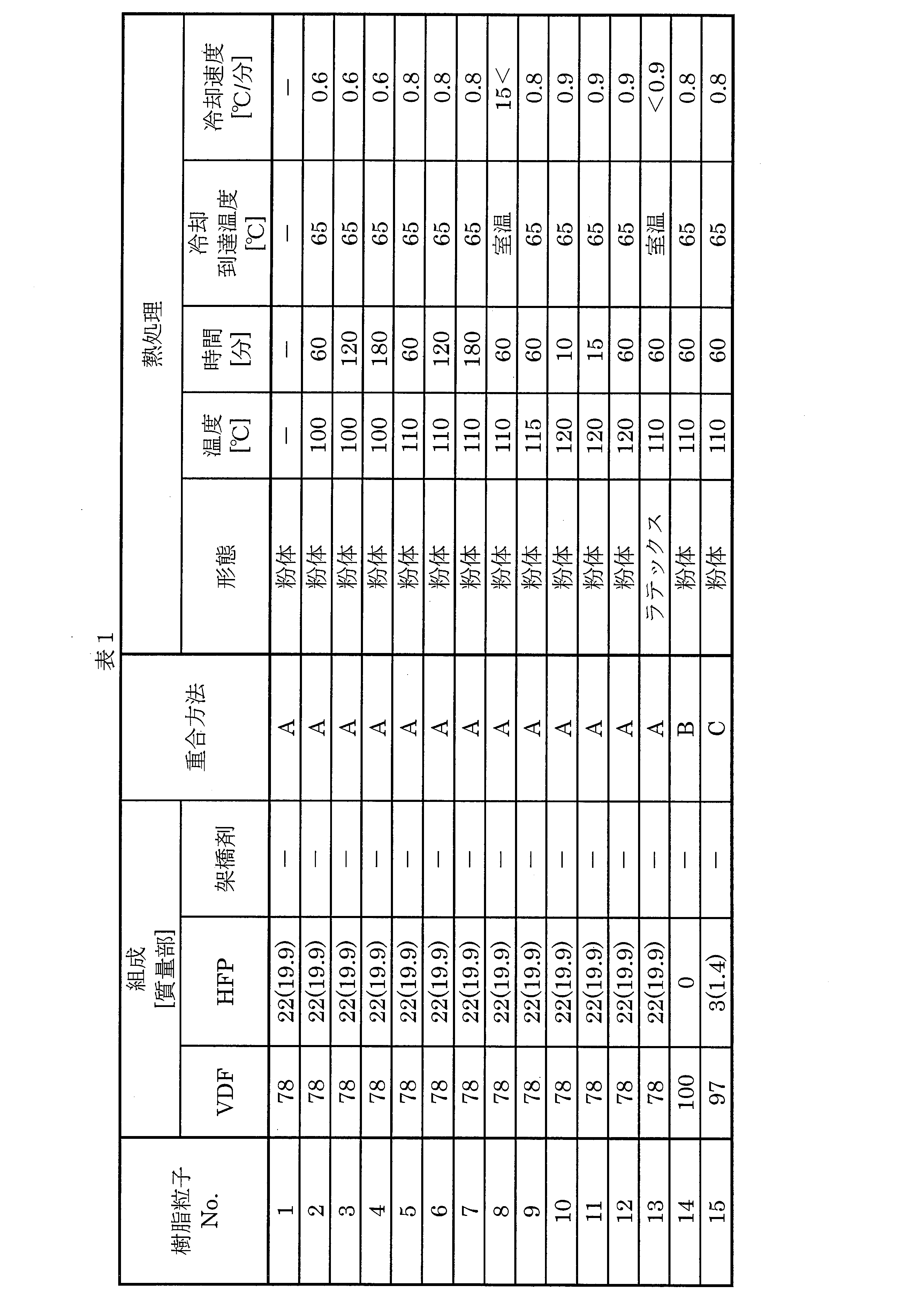
- Table 1 and Table 2 show the composition of the raw materials, the polymerization method and the heat treatment conditions for each of the resin particles 1 to 30.
- the values in parentheses indicate the amount of HFP introduced into the polymer (the content of the structural units derived from HFP in the obtained polymer).
- the upper part shows the amount of the monomer of the core particle
- the lower part shows the amount of the monomer of the shell.
- the weight ratio between the core particles and the shell in the resin particles 19 and 20 (core particle / shell) is 50/50.
- the temperature increase / decrease cycle is a cycle in which the temperature is temporarily increased from 25 ° C. to 230 ° C. at a rate of 5 ° C./min, and then decreased from 230 ° C. to 25 ° C. at a rate of 5 ° C./min.
- the peak temperature a of the melting peak (first peak) having the largest endothermic amount was determined. Further, from the DSC curve in the second cycle, the peak temperature b of the melting peak (second peak) having the largest endothermic amount was determined. Then, a value (ab) obtained by subtracting b from a was obtained.
- the area AH of the portion at a temperature higher than 115 ° C., the area AL of the portion at a temperature lower than 115 ° C., and the ratio AL / AH of AL to AH were determined.
- Dispersion Particle Size Each of the resin particles 1 to 30 was dispersed in propylene carbonate at room temperature so as to be 5% by mass to prepare a dispersion A.
- the dispersed particle size of the particles in the dispersion A was measured using a particle size analyzer Microtrac MT3300EXII (manufactured by Microtrac BELL). Ethanol is put into the sample circulation line and the mixing tank, and an appropriate amount of the dispersion liquid is dropped into the mixing tank (volume: about 200 mL). Then, ultrasonic waves are irradiated for 180 seconds to measure the particle size, and the integrated value in the volume-based particle size distribution is measured. The particle size at 50% (Dv50) was taken as the dispersed particle size.
- Viscosity (viscosity, viscosity ratio and viscosity peak temperature)
- Each of the resin particles 1 to 30 was dispersed in propylene carbonate at room temperature so as to be 5% by mass to prepare a dispersion.
- the viscosity of the dispersion was measured in the range of 25 ° C. to 80 ° C. using a viscoelasticity measuring device “ARES-G2” (manufactured by TA Instruments).
- the viscosity of propylene carbonate was measured.
- the viscosity of the dispersion at 25 ° C. was C
- the viscosity of propylene carbonate was D
- the ratio C / D of the viscosity C to the viscosity D was determined as the viscosity ratio.
- Table 3 and Table 4 show the physical properties of the dispersed particles for the resin particles 1 to 30.
- Table 5 shows the physical properties of the dispersion liquid for the resin particles 1 to 30.
- the resin particles 2 to 9, 14 to 17, 19, 20 and 22 to 25 have ab of 2 ° C. or less, HP of 21 mW / g or more, and dispersion.
- the particle size is 80 ⁇ m or less.
- these resin particles have a low solid content change rate. Further, since the temperature range from room temperature to the viscosity peak temperature is wide, it can be seen that the composition has good dispersibility (fluidity) in a sufficiently wide temperature range in a non-aqueous solvent.
- the viscosity peak temperature in the non-aqueous solvent is sufficiently lower than the melting point of the resin particles, the polymer particles can be melted by heating (pressing) at a low temperature for a short time and then cooled to form a polymer gel electrolyte. Therefore, it is understood that a non-aqueous dispersion having sufficient fluidity and uniform gelling properties is constituted.
- the above resin particles have ab of 2 ° C or less and a C / D of 70 or less. Therefore, according to the above-described example, it is considered that the resin particles having the above two characteristics also constitute a non-aqueous dispersion having sufficient fluidity and uniform gelling characteristics.
- the resin particles 10 to 12, 18, 21, and 26 to 30 do not have the above-mentioned combination of features. Therefore, it is considered that at least one of the dispersibility (fluidity and dispersion stability) is insufficient due to a large dispersion particle size and an increase in viscosity during dispersion. Therefore, it is considered that these resin particles have a low expected value for forming a non-aqueous dispersion having sufficient dispersibility (fluidity and dispersion stability) and uniform gelling characteristics.
- the present invention can be suitably used for an electrolyte of a secondary battery, and the present invention is expected to realize a secondary battery having high reliability and performance.
Landscapes
- Chemical & Material Sciences (AREA)
- Chemical Kinetics & Catalysis (AREA)
- Electrochemistry (AREA)
- General Chemical & Material Sciences (AREA)
- Engineering & Computer Science (AREA)
- Manufacturing & Machinery (AREA)
- Inorganic Chemistry (AREA)
- Condensed Matter Physics & Semiconductors (AREA)
- Physics & Mathematics (AREA)
- General Physics & Mathematics (AREA)
- Health & Medical Sciences (AREA)
- Medicinal Chemistry (AREA)
- Polymers & Plastics (AREA)
- Organic Chemistry (AREA)
- Dispersion Chemistry (AREA)
- Secondary Cells (AREA)
- Cell Separators (AREA)
- Battery Electrode And Active Subsutance (AREA)
Abstract
Description
本実施形態に係る樹脂分散電解液は、非水電解液と、非水電解液に分散しているフッ化ビニリデン重合体の粒子とを含む。樹脂分散電解液は、後述する粒子を有する以外は、通常の二次電池用非水電解液と同様に構成することが可能である。
非水電解液は、非水溶媒と、溶媒に溶解された電解質とを含む。非水電解液には、例えば、二次電池用の公知の非水電解液を用いることができる。非水電解液における非水溶媒および電解質の含有量は、樹脂分散電解液の用途に応じて適宜に決めることが可能である。
非水溶媒は、後述の電解質を溶解する溶媒である。非水溶媒は一種でもそれ以上でもよい。非水溶媒としては、例えば、エチレンカーボネート、プロピレンカーボネート、ブチレンカーボネート、フロロエチレンカーボネートおよびジフロロエチレンカーボネート等の環状カーボネート;ジメチルカーボネート、ジエチルカーボネート、エチルメチルカーボネートおよびそのフッ素置換体等の鎖状カーボネート;γ-ブチロラクトンおよびγ-バレロラクトン等の環状エステル;ならびにこれらの混合溶媒等が挙げられる。フッ化ビニリデン重合体の分散安定性の観点から、非水溶媒は、プロピレンカーボネート、エチレンカーボネート、ジメチルカーボネート、ジエチルカーボネート、およびメチルエチルカーボネートからなる群から選択される一以上の化合物であることが好ましい。
電解質は、非水溶媒に溶解して電荷の授受に供する物質である。電解質には、二次電池に用いられる電解質を好適に用いることが可能である。電解質は、一種でもそれ以上でもよい。電解質としては、LiPF6、LiBF4、LiClO4、LiAsF6、LiSbF6、LiCF3SO3、LiC4F9SO3、LiBPh4、LiCl、LiBr、LiCH3SO3、LiN(CF3SO2)2およびLiC(CF3SO2)3等が挙げられる。これらのうち、LiPF6、LiAsF6、LiClO4、LiBF4、LiCl、LiBr、LiCH3SO3、LiCF3SO3、LiN(CF3SO2)2、およびLiC(CF3SO2)3からなる群から選択される一以上の化合物であることが好ましい。
樹脂分散電解液に含有される粒子は、フッ化ビニリデン重合体で構成されている。
本実施形態に係るフッ化ビニリデン重合体は、フッ化ビニリデン由来の構成単位を主成分としている。ここで、「主成分としている」とは、フッ化ビニリデン重合体におけるフッ化ビニリデン由来の構成単位の含有率が50モル%以上であることを言う。
本実施形態における粒子は、フッ化ビニリデン重合体を合成する公知の重合方法によって得ることが可能である。当該重合方法には、例えば、乳化重合、ソープフリー乳化重合、ミニエマルション重合、懸濁重合、溶液重合、塊状重合等が挙げられる。これらの中でも、十分に小さな粒子を得る観点から、乳化重合、ソープフリー乳化重合、ミニエマルション重合または懸濁重合が好ましく、乳化重合および懸濁重合が特に好ましい。その他に、上記の粒子は、フッ化ビニリデン重合体の塊の破砕と分級によって製造されてもよい。
また、樹脂分散電解液は、本実施形態の効果が得られる範囲において、前述した粒子、非水溶媒および電解質以外の他の成分をさらに含有していてもよい。このような他の成分は、公知の二次電池における電解液の材料、および、樹脂がゲル化した際にゲル強度または耐熱性を向上させるための材料から適宜に選択することが可能である。当該他の成分の例には、アルミナ(Al2O3)および二酸化ケイ素(SiO2)などの無機フィラーが含まれる。
(粒子の分散粒径)
樹脂分散電解液における粒子の分散粒径は、樹脂分散電解液における粒子の良好な分散状態を実現させる観点から、非水溶媒を分散媒とする分散液(樹脂分散液)における当該粒子の分散粒径が80μm以下である。粒子の分散粒径は、70μm以下であることが好ましく、60μm以下であることがより好ましい。粒子の分散粒径の下限は、限定されないが、粒子の生産性の観点、あるいは、樹脂分散電解液の製造時における粒子の取り扱い性の観点から、0.01μm以上であることが好ましく、0.05μm以上であることがより好ましく、0.1μm以上であることがさらに好ましい。
本実施形態の粒子において、aからbを引いた値が-30℃以上2℃以下である。「a」は、粒子のみの示差走査熱量計での1回目の5℃/分での昇温測定による最も吸熱量の多い融解ピーク(「第一ピーク」とも言う)のピーク温度(℃)である。「b」は、粒子の示差走査熱量計での2回目の5℃/分での昇温測定による最も吸熱量の多い融解ピーク(「第二ピーク」とも言う)のピーク温度(℃)である。aとbの差が-30℃以上2℃以下の場合には、粒子を電解液に分散させた後でも樹脂分散電解液の粘度が上昇しにくく、良好な流動性を示す。aからbを引いた値が2℃よりも大きい場合には、粒子を電解液に分散させた際に粒子の結晶性の低い部分が溶融し、樹脂分散電解液の粘度が上がることがある。上記の流動性の観点から、a-bが-30℃以上1℃以下であることが好ましく、a-bが0℃以下であることがより好ましく、a-bが-3℃以下であることがさらに好ましい。
本実施形態に係る分散粒子は、AL/AHが1.5未満であることが、分散性(流動性)を高める観点から好ましい。「AL」は、示差走査熱量計での1回目の5℃/分での昇温測定において115℃よりも低温側の面積であり、「AH」は、115℃よりも高温側の面積である。分散性(流動性)を高める観点によれば、ALは小さいほど好ましい。
第一ピークのピーク高さの絶対値は、21mW/g以上である。ここで、上記の「ピーク高さ」とは、ベースラインから第一のピークのピークトップまでの距離(図中のHP)である。当該ピーク高さの絶対値は、低すぎると粒子の結晶性が低くなり、非水電解液に分散させた場合に粒子が溶融して非水電解液の粘度が増加するため流動性が不十分となることがある。分散粒子の非水電解液中での溶融を抑制する観点から、第一ピークのピーク高さの絶対値は、21mW/g以上であることが好ましく、30mW/g以上であることがより好ましい。
本実施形態に係る樹脂分散電解液では、非水溶媒を分散媒として樹脂粒子を分散させた樹脂分散液を、容器に収容して室温で撹拌したときに、固形分率Aと固形分率Bとの変化率が90%以下であることが分散性(分散安定性)の観点から好ましい。ここで言う固形分率Aとは、撹拌状態にある当該樹脂分散液の固形分率であり、固形分率Bとは、その後の静置時における当該樹脂分散液の上層部の固形分率である。上記の固形分率の変化率は、上記の観点から小さいほど好ましく、例えば80%以下であることがより好ましく、50%以下であることがさらに好ましい。


本実施形態に係る樹脂分散電解液の粘度は、非水溶媒を分散媒とする前述の粒子の分散液の25℃での粘度をC、非水溶媒の粘度をDとしたときにC/Dが200以下であることが、樹脂分散電解液における分散性(流動性)の向上の観点から好ましい。C/Dは、上記の観点から、好ましくは100以下で、さらに好ましくは70以下である。200を超えると、粒子が部分的に溶融し、樹脂分散電解液が増粘し、分散性(流動性)が不十分となることがある。
本実施形態の樹脂分散電解液において、粒子の一次粒径が10nm~1μmであることが、樹脂分散電解液の分散安定性を高める観点および均一かつ迅速なゲル化の観点から好ましい。当該一次粒径は、一次粒径の平均値であってもよい。一次粒径は、上記の観点から小さいほど好ましいが、粒子の取り扱い性を考慮して、本実施形態の効果が得られる範囲から適宜に決めることが可能である。たとえば、一次粒径は、10nm以上であることが好ましく、30nm以上であることがより好ましく、50nm以上ことがさらに好ましい。また、一次粒径の上限は、やはり上記の観点から700nm以下であることが好ましく、600nm以下であることがより好ましく、500nm以下であることがさらに好ましい。粒子の一次粒径は、50%以上が上記範囲内に入っていることが、前述の観点から好ましく、70%以上が含まれていることがより好ましい。一次粒径が大きすぎると樹脂分散電解液中で粒子が沈降しやすく、樹脂分散電解液の分散安定性が不十分になることがある。
本実施形態に係る樹脂分散電解液は、分散質が粒子のみである場合では、前述の樹脂分散液における60℃に加熱した場合の濁度が2以上であることが好ましい。この濁度が高い場合には、樹脂分散電解液を加熱(プレス)した際に、樹脂の拡散が適度に抑制され、冷却後に部材間にポリマーゲル電解質が適度にとどまることで部材間を好適に固定することができる。当該観点から、濁度は8以上であることがより好ましく、15以上であることがさらに好ましい。
本実施形態に係る樹脂分散電解液は、前述した分散粒径と融解ピーク高さの絶対値を有し、かつaからbを引いた値が-30℃以上2℃以下である粒子を非水電解液に分散させる以外は、樹脂分散液の公知の製造方法を利用して製造することが可能である。上記の熱特性を有する粒子は、当該粒子の加熱処理によって得ることが可能である。
本実施形態に係る樹脂分散電解液は、昇温により粒子の、部分的な溶融が生じ、樹脂分散電解液の粘度は上昇し始める。そして、粘度がピークとなる温度を境界として、迅速な溶融が進む。そして、粒子の溶融後、冷却することでゲル化しポリマーゲル電解質を形成する。このように、本実施形態に係る樹脂分散電解液は、粒子が十分に小さいことから樹脂分散電解液中での分散安定性に優れ、粘度ピーク温度よりも低い温度では、粒子を構成するフッ化ビニリデン重合体は溶融せず増粘が抑制されるので、高い流動性を有する。また、粘度ピーク温度よりも高い温度では、粒子が迅速に溶融し、冷却により樹脂分散電解液がゲル化する。なお、粘度ピーク温度とは、非水溶媒中で樹脂粒子が溶融する温度であり、非水溶媒中での粒子の融点とも言える。
前述した本実施形態の樹脂分散電解液は、ポリマーゲル電解質の製造に好適に用いられる。このようなポリマーゲル電解質は、前述の樹脂分散電解液を加熱(プレス)、冷却することによりゲル化させることにより製造される。ポリマーゲル電解質の製造において加熱(プレス)される樹脂分散電解液の温度は、フッ化ビニリデン重合体の非水電解液中での融点に応じて適宜に決めることができ、例えば50℃~150℃である。粒子が樹脂分散電解液中に分散している場合、分散粒子は電解液中の非水溶媒に適度に膨潤しているため、非水電解液中での粒子の融点は粒子のみの融点よりも低くなる。加熱(プレス)時間は、加熱(プレス)時における樹脂分散電解液を取り巻く環境に応じて、例えば1秒から8時間までの範囲から適宜に決定してよい。
前述の樹脂分散電解液は、所定の部材の存在下でゲル化させることにより、ポリマーゲル電解質を備える部材を提供し得る。このような所定の部材は、ポリマーゲル電解質を有している状態で使用される部材が好ましく、その例には、二次電池用のセパレータおよび電極が含まれる。このようなポリマーゲル電解質を備えたセパレータ、あるいは、ポリマーゲル電解質を備えた電極は、その最終製品である二次電池のための一部品として有用となり得る。
前述の樹脂分散電解液は、二次電池の電解質に有用である。樹脂分散電解液から形成されたポリマーゲル電解質と有する二次電池は、例えば、正極と、負極と、両極間に配置されるセパレータと、これらの間に一体的に介在するポリマーゲル電解質とを有する。「ポリマーゲルが一体的に介在する」とは、例えば、一度にゲル化したポリマーゲルのみによって、電極とセパレータなどの接着されるべき部材が接着されていることを意味する。ポリマーゲルが一体的に介在することにより、部材同士のずれを防止でき、また部材間に隙間ができることを防止することができる。
ポリマーゲル電解質は、前述した樹脂分散電解液の注入、加熱(プレス)および冷却によって形成される。樹脂分散電解液中の粒子は、前述したa℃とb℃との差が-30℃以上2℃以下であることから、良好な流動性を有している。よって、二次電池における電池要素が有するような細かな構造にも迅速に流入する。また、樹脂分散電解液の粒子は、前述したような十分に小さな分散粒径を有している。よって、上記の細かな構造においても十分に均一な状態で充満する。そして、樹脂分散電解液中の粒子は、実質的に粘度ピーク温度よりも高い温度で迅速に融解する。よって、従来のポリマーゲル電解質におけるポリマー化(ゲル化)に比べて、ゲル化のための加熱(プレス)温度を十分に低くすることが可能であり、また、加熱(プレス)時間を十分に短くすることが可能である。よって、従来のポリマーゲル電解質におけるポリマー化(ゲル化)に比べて、ポリマーゲル電解質およびそれに接する部材(前述の電池要素など)に対する、樹脂を溶融させゲル化するための加熱(プレス)による熱劣化を抑制することが可能となる。さらに本実施形態の樹脂分散液は、樹脂の粒径とフッ化ビニリデン重合体の組成を調整することにより、加熱(プレス)温度及び時間も調整できることから、均質かつ電解液の分解が抑制されたポリマーゲル電解質の形成が期待される。
以上の説明から明らかなように、本実施形態に係る樹脂分散電解液は、非水電解液と、前記非水電解液に分散しているフッ化ビニリデン重合体の粒子とを含む。非水溶媒を分散媒とする(樹脂分散液における)粒子の分散粒径が80μm以下である。そして、粒子の示差走査熱量計での1回目の5℃/分での昇温測定による最も吸熱量の多い第一ピークのピーク温度をa℃とし、粒子の示差走査熱量計での2回目の5℃/分での昇温測定による最も吸熱量の多い第二ピークのピーク温度をb℃としたとき、aからbをひいた値が-30℃以上2℃以下であり、第一ピークのピーク高さの絶対値が21mW/g以上である。
フッ化ビニリデン重合体の樹脂粒子として以下の樹脂粒子1~30を準備した。
オートクレーブに330質量部の水をいれた。脱気後、0.7質量部のパーフルオロオクタン酸アンモニウム塩(PFOA)と0.1質量部の酢酸エチルとを入れ、次いで14.7質量部のフッ化ビニリデン(VDF)と22質量部のヘキサフルオロプロピレン(HFP)とを入れた。
樹脂粒子1の粉末をオーブン中にて100℃で60分間加熱し、その後60分間かけて65℃まで冷却して樹脂粒子2を得た。冷却速度は0.6℃/分であった。
樹脂粒子1の粉末をオーブン中にて100℃で120分間加熱し、その後60分間かけて65℃まで冷却して樹脂粒子3を得た。冷却速度は0.6℃/分であった。
樹脂粒子1の粉末をオーブン中にて100℃で180分間加熱し、その後60分間かけて65℃まで冷却して樹脂粒子4を得た。冷却速度は0.6℃/分であった。
樹脂粒子1の粉末をオーブン中にて110℃で60分間加熱し、その後60分間かけて65℃まで冷却して樹脂粒子5を得た。冷却速度は0.8℃/分であった。
樹脂粒子1の粉末をオーブン中にて110℃で120分間加熱し、その後60分間かけて65℃まで冷却して樹脂粒子6を得た。冷却速度は0.8℃/分であった。
樹脂粒子1の粉末をオーブン中にて110℃で180分間加熱し、その後60分間かけて65℃まで冷却して樹脂粒子7を得た。冷却速度は0.8℃/分であった。
樹脂粒子1の粉末をオーブン中にて110℃で60分間加温し、その後直ちにオーブンから取り出して急冷して樹脂粒子8を得た。冷却速度は15℃/分以上であった。
樹脂粒子1の粉末をオーブン中にて115℃で60分間加温し、その後60分間かけて65℃まで冷却して樹脂粒子9を得た。冷却速度は0.8℃/分であった。
樹脂粒子1の粉末をオーブン中にて120℃で10分間加温し、その後60分間かけて65℃まで冷却して樹脂粒子10を得た。冷却速度は0.9℃/分であった。
樹脂粒子1の粉末をオーブン中にて120℃で15分間加温し、その後60分間かけて65℃まで冷却して樹脂粒子11を得た。冷却速度は0.9℃/分であった。
樹脂粒子1の粉末をオーブン中にて120℃で60分間加温し、その後60分間かけて65℃まで冷却して樹脂粒子12を得た。冷却速度は0.9℃/分であった。
樹脂粒子1のラテックスをオーブン中にて110℃で60分間加温し、次いで110℃を、60分間維持し、その後一晩かけて室温(RT、20℃)まで冷却した。得られた樹脂粒子1のラテックスを、凍結乾燥機にて室温で8時間乾燥し、樹脂粒子13を得た。
オートクレーブに275質量部の水をいれ、脱気後、1質量部のPFOAを仕込み、さらにオートクレーブ内に、0.25質量部の酢酸エチル、30.6質量部のVDFを入れた。
オートクレーブに330質量部の水をいれ、脱気後、0.5質量部のPFOAを仕込み、0.15質量部の酢酸エチルと33.7質量部のVDFと3質量部のHFPとを前記オートクレーブに入れた。
PFOAの量を1.2質量部、酢酸エチルの量を0.05質量部、VDFの量を31.7質量部、HFPの量を5質量部とした以外は樹脂粒子の製造例15と同じ方法で樹脂粒子を得た。
VDFの量を24.7質量部、HFPの量を12質量部とした以外は樹脂粒子の製造例15と同様にして樹脂粒子を得た。
容積2Lのオートクレーブに、イオン交換水256質量部、メチルセルロース0.15質量部、VDF90質量部、HFP10質量部、ジ-n-プロピルパーオキシジカーボネート0.4質量部を入れ、29℃で重合した。得られたVDF-HFP共重合体を、95℃で60分間熱処理した後、脱水、水洗し、さらに80℃で20時間乾燥して、VDF-HFP共重合体粒子を得た。この粒子を樹脂粒子18として用いた。このような懸濁重合を重合方法Dとする。
オートクレーブに330質量部の水をいれ、脱気後、1質量部のPFOAを仕込み、0.05質量部の酢酸エチル、9質量部のVDF、30質量部のHFPをオートクレーブにさらに入れた。
樹脂粒子19の粉末をオーブン中にて110℃で60分間加温し、その後60分間かけて65℃まで冷却して樹脂粒子20を得た。冷却速度は0.8℃/分であった。
VDFの量を9.7質量部、HFPの量を27.0質量部とした以外は樹脂粒子の製造例15と同様にして樹脂粒子21を得た。
樹脂粒子21の粉末をオーブン中にて100℃で60分間加温し、その後60分間かけて65℃まで冷却して樹脂粒子22を得た。冷却速度は0.6℃/分であった。
樹脂粒子21の粉末をオーブン中にて110℃で60分間加温し、その後60分間かけて65℃まで冷却して樹脂粒子23を得た。冷却速度は0.8℃/分であった。
樹脂粒子21の粉末をオーブン中にて115℃で60分間加温し、その後60分間かけて65℃まで冷却して樹脂粒子24を得た。冷却速度は0.8℃/分であった。
樹脂粒子21の粉末をオーブン中にて120℃で60分間加温し、その後60分間かけて65℃まで冷却して樹脂粒子25を得た。冷却速度は0.9℃/分であった。
樹脂粒子21の粉末をオーブン中にて134℃で60分間加温し、その後60分間かけて65℃まで冷却して樹脂粒子26を得た。冷却速度は1.2℃/分であった。
樹脂粒子21の粉末をオーブン中にて139℃で60分間加温し、その後60分間かけて65℃まで冷却して樹脂粒子27を得た。冷却速度は1.3℃/分であった。
樹脂粒子21の粉末をオーブン中にて144℃で60分間加温し、その後60分間かけて65℃まで冷却して樹脂粒子28を得た。冷却速度は1.3℃/分であった。
VDFの量を9.0質量部、HFPの量を37.0質量部、連続添加するVDFの量を54.0質量部、昇温後の圧力を3.2MPaとした以外は樹脂粒子の製造例1と同様にして樹脂粒子29を得た。
樹脂粒子29の粉末をオーブン中にて110℃で60分間加温し、その後60分間かけて65℃まで冷却して樹脂粒子30を得た。冷却速度は0.8℃/分であった。

(1)一次粒径
乳化重合で得られた樹脂粒子(樹脂粒子1~17、19~30)について、平均粒子径を動的光散乱法の正則化解析によって算出した。具体的には、BECKMAN COULTER社製「DelsaMaxCORE」を使用し、JIS Z 8828に準拠してラテックス中の樹脂粒子の粒子径を測定し、正則化解析によって得られる最も大きいピークの値を一次粒子径とした。一方、懸濁重合によって得た樹脂粒子(樹脂粒子18)の一次粒子径は、以下のようにして求めた。すなわち、粉体化したVDF-HFP共重合体粒子3000個の画像を撮影し、画像から長さを測定可能な任意の画像解析ソフトを用いて撮影された各粒子が円形と仮定した場合の樹脂粒子の粒径の平均値を算出し、一次粒子径とした。
樹脂粒子1~30のそれぞれについて、容器内においてプロピレンカーボネートに5質量%になるように室温で分散させ、5%分散液を作製した。攪拌した状態で分散液から約2gを分取し、これを分散直後サンプルとした。残りの5%分散液5mLを10mL試験管に入れ、15分間静置し、上澄み2mLを分取し、15分後サンプルとした。分散直後サンブルと15分後サンプルを150℃で3時間乾燥させ、分散直後サンプルの固形分の重量W1と15分後サンプルの固形分の重量W2とを測定し、静置前後における固形分の変化率を下記式より算出した。

10mgの樹脂粒子1~30のそれぞれを、METTLER社製の示差走査熱量計「DSC-1」の測定セルにセットし、窒素ガス雰囲気中で、二回の昇温-降温サイクルを実施し、各回のサイクルでDSC曲線を得た。昇温-降温サイクルは、温度25℃から5℃/分の昇温速度で230℃まで一旦昇温し、230℃から5℃/分の降温速度で25℃まで降温するサイクルである。一回目のサイクルにおけるDSC曲線から、最も吸熱量の多い融解ピーク(第一ピーク)のピーク温度aを求めた。また、二回目のサイクルにおけるDSC曲線から、最も吸熱量の多い融解ピーク(第二ピーク)のピーク温度bを求めた。そして、aからbをひいた値(a-b)を求めた。
樹脂粒子1~30のそれぞれを、プロピレンカーボネートに5質量%になるように室温で分散させ、分散液Aを作製した。分散液A中の粒子の分散粒径を、粒度分析計Microtrac MT3300EXII(MicrotracBELL社製)を用いて測定した。サンプル循環ラインおよび混合槽にエタノールを入れ、分散液を混合槽内(容積約200mL)に適量滴下したのち、超音波を180秒間照射して粒径を測定し、体積基準の粒度分布における積算値50%での粒径(Dv50)を分散粒径とした。
樹脂粒子1~30のそれぞれを、プロピレンカーボネートに1質量%になるように60℃で分散(または溶融)させ、1%分散液を作製した。20±2℃にて、濁度計「NDH2000」(日本電色工業社製)を用いて測定方法3(JIS K 7136に準じた方法)で1%分散液の濁度を測定した。
樹脂粒子1~30のそれぞれについて、プロピレンカーボネートに5質量%になるように室温で分散させ、分散液を作製した。25℃から80℃の範囲にて、粘弾性測定装置「ARES-G2」(TAインスツルメント社製)を用いて分散液の粘度を測定した。同様にプロピレンカーボネートの粘度を測定した。そして、25℃での分散液の粘度をC、プロピレンカーボネートの粘度をDとし、粘度比として粘度Dに対する粘度Cの比C/Dを求めた。
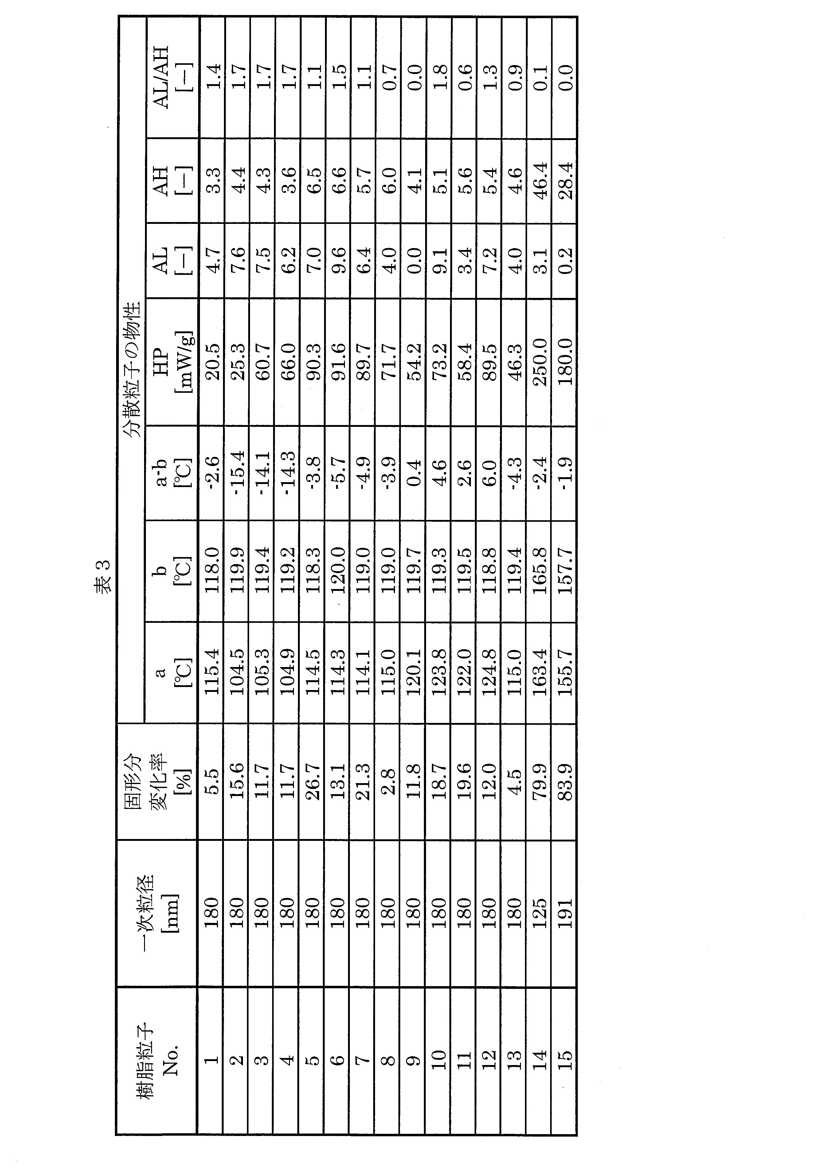


表3~5から明らかなように、樹脂粒子2~9、14~17、19、20および22~25は、a-bが2℃以下であり、HPが21mW/g以上であり、かつ分散粒径が80μm以下である。そして、これらの樹脂粒子は、低い固形分変化率を有する。また、室温から粘度ピーク温度までの温度範囲が広いことから、非水溶媒中で十分に広い温度範囲で良好な分散性(流動性)を有することがわかる。また非水溶媒中での粘度ピーク温度は、樹脂粒子の融点に比べて十分に低いので、低い温度で短時間の加熱(プレス)で溶融し、その後冷却によりポリマーゲル電解質を形成できる。よって、十分な流動性と均質なゲル化特性とを有する非水系分散液を構成することがわかる。
Claims (17)
- 非水電解液と、前記非水電解液に分散しているフッ化ビニリデン重合体の粒子と、を含む樹脂分散電解液であって、
前記粒子の非水溶媒中での分散粒径が80μm以下であり、
前記粒子の示差走査熱量計での1回目の5℃/分での昇温測定による最も吸熱量の多い融解ピークのピーク温度をa℃とし、
前記粒子の示差走査熱量計での2回目の5℃/分での昇温測定による最も吸熱量の多い融解ピークのピーク温度をb℃としたとき、
aからbを引いた値が-30℃以上2℃以下であり、
前記1回目の昇温測定による最も吸熱量の多い融解ピークのピーク高さの絶対値が21mW/g以上である、樹脂分散電解液。 - 前記粒子の示差走査熱量計での1回目の昇温測定による最も吸熱量の多い融解ピークにおける、115℃よりも低温側の面積をALとし、115℃よりも高温側の面積をAHとしたとき、AL/AHが1.5未満である、請求項1に記載の樹脂分散電解液。
- 非水溶媒を分散媒とする前記粒子の分散液を容器に収容して撹拌したときに、撹拌停止直後における当該分散液の上層部の固形分率と、その後の静置時における当該分散液の上層部の固形分率から求めた変化率が90%以下である、請求項1または2に記載の樹脂分散電解液。
- 非水溶媒を分散媒とする前記粒子の分散液の25℃における粘度をC、前記非水溶媒の粘度をDとしたときにC/Dが200以下である、請求項1~3のいずれか一項に記載の樹脂分散電解液。
- 前記フッ化ビニリデン重合体がフッ化ビニリデンに由来する構成単位と、前記フッ化ビニリデンと共重合可能な単量体に由来する構成単位とを含み、
前記フッ化ビニリデン重合体の融点が85℃以上175℃以下である、請求項1~4のいずれか一項に記載の樹脂分散電解液。 - 前記フッ化ビニリデンと共重合可能な単量体は、ヘキサフルオロプロピレン、クロロトリフルオロエチレン、トリフルオロエチレン、テトラフルオロエチレン、ヘキサフルオロエチレンおよびフルオロアルキルビニルエーテル、からなる群から選ばれる一以上の化合物である、請求項5に記載の樹脂分散電解液。
- 前記フッ化ビニリデン重合体は、フッ化ビニリデンに由来する構成単位とヘキサフルオロプロピレンに由来する構成単位とを含み、
前記フッ化ビニリデン重合体におけるヘキサフルオロプロピレンに由来する構成単位の含有量をX、前記粒子における前記b℃をYとしたときに、Xは0質量%以上35質量%以下であり、Yは85℃以上175℃以下である、請求項6に記載の樹脂分散電解液。 - 前記粒子の一次粒径が10nm~1μmである、請求項1~7のいずれか一項に記載の樹脂分散電解液。
- 前記非水電解液は、非水溶媒と電解質とを含有し、
前記非水溶媒は、プロピレンカーボネート、エチレンカーボネート、ジメチルカーボネート、ジエチルカーボネート、およびメチルエチルカーボネートからなる群から選択される一以上の化合物である、請求項1~8のいずれか一項に記載の樹脂分散電解液。 - 前記電解質は、LiPF6、LiAsF6、LiClO4、LiBF4、LiCl、LiBr、LiCH3SO3、LiCF3SO3、LiN(CF3SO2)2、およびLiC(CF3SO2)3からなる群から選択される一以上の化合物である、請求項9に記載の樹脂分散電解液。
- 請求項1~10のいずれか一項に記載された樹脂分散電解液から形成されたポリマーゲル電解質。
- 請求項11に記載のポリマーゲル電解質を備えたセパレータ。
- 請求項11に記載のポリマーゲル電解質を備えた電極。
- 樹脂分散電解液を加熱またはプレスを伴う加熱、冷却することによりゲル化させるポリマーゲル電解質の製造方法であって、
前記樹脂分散電解液に、請求項1~10のいずれか一項に記載の樹脂分散電解液を用いる、ポリマーゲル電解質の製造方法。 - 非水溶媒を分散媒とする前記粒子の分散液の25℃における粘度をC、前記非水溶媒の粘度をDとしたときにC/Dが200以下である、請求項14に記載のポリマーゲル電解質の製造方法。
- 正極と、負極と、両極間に配置されるセパレータと、これらの間に介在する請求項11に記載のポリマーゲル電解質と、を有する二次電池。
- 正極、負極およびこれらの間に配置されるセパレータを含む電池要素が収容された電池容器に樹脂分散電解液を注入する工程と、前記電池容器を加熱またはプレスを伴う加熱、冷却して前記樹脂分散電解液をゲル化させる工程と、を含む二次電池の製造方法であって、
前記樹脂分散電解液に、請求項1~10のいずれか一項に記載の樹脂分散電解液を用いる、二次電池の製造方法。
Priority Applications (3)
| Application Number | Priority Date | Filing Date | Title |
|---|---|---|---|
| KR1020217010209A KR102367508B1 (ko) | 2018-09-14 | 2019-09-04 | 수지 분산 전해액, 폴리머 겔 전해질 및 이의 제조방법, 및 이차전지 및 이의 제조방법 |
| JP2020545952A JP6804709B2 (ja) | 2018-09-14 | 2019-09-04 | 樹脂分散電解液、ポリマーゲル電解質およびその製造方法、ならびに、二次電池およびその製造方法 |
| CN201980054939.7A CN112640181B (zh) | 2018-09-14 | 2019-09-04 | 树脂分散电解液、聚合物凝胶电解质及其制造方法以及二次电池及其制造方法 |
Applications Claiming Priority (2)
| Application Number | Priority Date | Filing Date | Title |
|---|---|---|---|
| JP2018-172971 | 2018-09-14 | ||
| JP2018172971 | 2018-09-14 |
Publications (1)
| Publication Number | Publication Date |
|---|---|
| WO2020054548A1 true WO2020054548A1 (ja) | 2020-03-19 |
Family
ID=69776806
Family Applications (1)
| Application Number | Title | Priority Date | Filing Date |
|---|---|---|---|
| PCT/JP2019/034798 Ceased WO2020054548A1 (ja) | 2018-09-14 | 2019-09-04 | 樹脂分散電解液、ポリマーゲル電解質およびその製造方法、ならびに、二次電池およびその製造方法 |
Country Status (4)
| Country | Link |
|---|---|
| JP (1) | JP6804709B2 (ja) |
| KR (1) | KR102367508B1 (ja) |
| CN (1) | CN112640181B (ja) |
| WO (1) | WO2020054548A1 (ja) |
Cited By (2)
| Publication number | Priority date | Publication date | Assignee | Title |
|---|---|---|---|---|
| WO2022172951A1 (ja) * | 2021-02-10 | 2022-08-18 | ダイキン工業株式会社 | 化合物、組成物、電気化学デバイス、リチウムイオン二次電池及びモジュール |
| JPWO2023058543A1 (ja) * | 2021-10-05 | 2023-04-13 |
Citations (5)
| Publication number | Priority date | Publication date | Assignee | Title |
|---|---|---|---|---|
| JPS6059604A (ja) * | 1983-09-12 | 1985-04-06 | ダイキン工業株式会社 | 高誘電性高分子材料およびその製法 |
| JPH10261437A (ja) * | 1997-01-20 | 1998-09-29 | Matsushita Electric Ind Co Ltd | ポリマ電解質およびそれを用いたリチウム・ポリマ電池 |
| JPH1186630A (ja) * | 1997-09-16 | 1999-03-30 | Yuasa Corp | ゲル電解質 |
| JPH11204136A (ja) * | 1998-01-08 | 1999-07-30 | Toyota Motor Corp | バイポーラ型リチウムイオン2次電池及びその製造方法 |
| JP2006104391A (ja) * | 2004-10-07 | 2006-04-20 | Daikin Ind Ltd | フルオロポリマー水性分散液の製造方法 |
Family Cites Families (5)
| Publication number | Priority date | Publication date | Assignee | Title |
|---|---|---|---|---|
| CN1194278A (zh) * | 1997-01-20 | 1998-09-30 | 松下电器产业株式会社 | 聚合物电解质和使用该电解质的锂-聚合物电池 |
| JP2000013252A (ja) | 1998-06-26 | 2000-01-14 | Kenwood Corp | 送信回路 |
| JP2005056701A (ja) | 2003-08-05 | 2005-03-03 | Sony Corp | 電池の製造方法および製造装置 |
| JP4774941B2 (ja) * | 2005-11-14 | 2011-09-21 | ソニー株式会社 | ゲル電解質およびゲル電解質電池 |
| JP6829943B2 (ja) * | 2016-03-10 | 2021-02-17 | 株式会社クレハ | ゲル状電解質およびその調製方法 |
-
2019
- 2019-09-04 JP JP2020545952A patent/JP6804709B2/ja active Active
- 2019-09-04 WO PCT/JP2019/034798 patent/WO2020054548A1/ja not_active Ceased
- 2019-09-04 KR KR1020217010209A patent/KR102367508B1/ko active Active
- 2019-09-04 CN CN201980054939.7A patent/CN112640181B/zh active Active
Patent Citations (5)
| Publication number | Priority date | Publication date | Assignee | Title |
|---|---|---|---|---|
| JPS6059604A (ja) * | 1983-09-12 | 1985-04-06 | ダイキン工業株式会社 | 高誘電性高分子材料およびその製法 |
| JPH10261437A (ja) * | 1997-01-20 | 1998-09-29 | Matsushita Electric Ind Co Ltd | ポリマ電解質およびそれを用いたリチウム・ポリマ電池 |
| JPH1186630A (ja) * | 1997-09-16 | 1999-03-30 | Yuasa Corp | ゲル電解質 |
| JPH11204136A (ja) * | 1998-01-08 | 1999-07-30 | Toyota Motor Corp | バイポーラ型リチウムイオン2次電池及びその製造方法 |
| JP2006104391A (ja) * | 2004-10-07 | 2006-04-20 | Daikin Ind Ltd | フルオロポリマー水性分散液の製造方法 |
Cited By (9)
| Publication number | Priority date | Publication date | Assignee | Title |
|---|---|---|---|---|
| WO2022172951A1 (ja) * | 2021-02-10 | 2022-08-18 | ダイキン工業株式会社 | 化合物、組成物、電気化学デバイス、リチウムイオン二次電池及びモジュール |
| JP2022122846A (ja) * | 2021-02-10 | 2022-08-23 | ダイキン工業株式会社 | 化合物、組成物、電気化学デバイス、リチウムイオン二次電池及びモジュール |
| JP7168897B2 (ja) | 2021-02-10 | 2022-11-10 | ダイキン工業株式会社 | 化合物、組成物、電気化学デバイス、リチウムイオン二次電池及びモジュール |
| CN116848080A (zh) * | 2021-02-10 | 2023-10-03 | 大金工业株式会社 | 化合物、组合物、电化学器件、锂离子二次电池及组件 |
| EP4293007A4 (en) * | 2021-02-10 | 2025-03-19 | Daikin Industries, Ltd. | Compound, composition, electrochemical device, lithium ion secondary battery and module |
| CN116848080B (zh) * | 2021-02-10 | 2026-03-20 | 大金工业株式会社 | 化合物、组合物、电化学器件、锂离子二次电池及组件 |
| JPWO2023058543A1 (ja) * | 2021-10-05 | 2023-04-13 | ||
| WO2023058543A1 (ja) * | 2021-10-05 | 2023-04-13 | 株式会社クレハ | フッ化ビニリデン重合体溶液 |
| JP7716488B2 (ja) | 2021-10-05 | 2025-07-31 | 株式会社クレハ | フッ化ビニリデン重合体溶液 |
Also Published As
| Publication number | Publication date |
|---|---|
| KR102367508B1 (ko) | 2022-02-24 |
| CN112640181B (zh) | 2021-09-24 |
| KR20210054564A (ko) | 2021-05-13 |
| JPWO2020054548A1 (ja) | 2021-02-15 |
| JP6804709B2 (ja) | 2020-12-23 |
| CN112640181A (zh) | 2021-04-09 |
Similar Documents
| Publication | Publication Date | Title |
|---|---|---|
| CN112585795B (zh) | 树脂分散电解液、聚合物凝胶电解质及其制造方法以及二次电池及其制造方法 | |
| CN112956072B (zh) | 电化学元件用功能层、带电化学元件用功能层的间隔件及电化学元件 | |
| CN114556680B (zh) | 锂离子二次电池间隔件用功能层、带有锂离子二次电池间隔件用功能层的间隔件、锂离子二次电池、以及它们的制造方法 | |
| KR102683937B1 (ko) | 전기 화학 소자 기능층용 조성물, 전기 화학 소자용 기능층 및 전기 화학 소자 | |
| WO2020246394A1 (ja) | 電気化学素子用機能層付きセパレータ、および電気化学素子 | |
| JP6908032B2 (ja) | 非水系二次電池機能層用組成物、非水系二次電池用機能層、及び非水系二次電池 | |
| WO2017073022A1 (ja) | 非水系二次電池接着層用組成物、非水系二次電池用接着層、非水系二次電池用接着層付きセパレータ、非水系二次電池用接着層付き電極、並びに、非水系二次電池およびその製造方法 | |
| CN107771351A (zh) | 固体聚合物电解质和包含其的电化学装置 | |
| WO2014185072A1 (ja) | リチウムイオン二次電池正極用結着材組成物、リチウムイオン二次電池正極用スラリー組成物およびその製造方法、リチウムイオン二次電池用正極の製造方法、並びに、リチウムイオン二次電池 | |
| JP2017098203A (ja) | 非水系二次電池接着層用組成物、非水系二次電池用接着層、及び非水系二次電池 | |
| CN1147955C (zh) | 制备聚合物电解质电化学电池的方法 | |
| CN112585211B (zh) | 偏氟乙烯系聚合物粉末、粘合剂组合物、电极合剂以及电极的制造方法 | |
| JP6829943B2 (ja) | ゲル状電解質およびその調製方法 | |
| JP6804709B2 (ja) | 樹脂分散電解液、ポリマーゲル電解質およびその製造方法、ならびに、二次電池およびその製造方法 | |
| JP6829941B2 (ja) | ゲル状電解質およびその調製方法 | |
| WO2021200049A1 (ja) | 電気化学素子機能層用組成物、電気化学素子用機能層、電気化学素子用積層体、及び電気化学素子 | |
| TWI442617B (zh) | Non-aqueous electrolyte secondary battery negative electrode mixture, nonaqueous electrolyte secondary battery negative electrode and nonaqueous electrolyte secondary battery | |
| WO2019170694A1 (en) | A process for the preparation of a solid polymer electrolyte useful in batteries | |
| JP4781547B2 (ja) | 高分子ゲル電解質および電池 | |
| JP2017084651A (ja) | 非水系二次電池接着層用組成物、非水系二次電池用接着層、及び非水系二次電池 | |
| JP3654180B2 (ja) | 固体状電解質およびそれを用いた電池 | |
| EP4253430B1 (en) | Vinylidene fluoride polymer composition and method for producing same, resin composition, electrode mixture, electrode containing these, and method for producing same | |
| JP2004296335A (ja) | 高分子固体電解質二次電池 | |
| WO2021200083A1 (ja) | 電気化学素子機能層用組成物、電気化学素子用積層体、および電気化学素子 | |
| CN112789756A (zh) | 凝胶状电解质以及非水电解质二次电池 |
Legal Events
| Date | Code | Title | Description |
|---|---|---|---|
| 121 | Ep: the epo has been informed by wipo that ep was designated in this application |
Ref document number: 19860270 Country of ref document: EP Kind code of ref document: A1 |
|
| ENP | Entry into the national phase |
Ref document number: 2020545952 Country of ref document: JP Kind code of ref document: A |
|
| NENP | Non-entry into the national phase |
Ref country code: DE |
|
| ENP | Entry into the national phase |
Ref document number: 20217010209 Country of ref document: KR Kind code of ref document: A |
|
| 122 | Ep: pct application non-entry in european phase |
Ref document number: 19860270 Country of ref document: EP Kind code of ref document: A1 |