WO2020054522A1 - 耐高面圧部品およびその製造方法 - Google Patents
耐高面圧部品およびその製造方法 Download PDFInfo
- Publication number
- WO2020054522A1 WO2020054522A1 PCT/JP2019/034668 JP2019034668W WO2020054522A1 WO 2020054522 A1 WO2020054522 A1 WO 2020054522A1 JP 2019034668 W JP2019034668 W JP 2019034668W WO 2020054522 A1 WO2020054522 A1 WO 2020054522A1
- Authority
- WO
- WIPO (PCT)
- Prior art keywords
- steel
- pressure resistant
- high surface
- carburizing
- surface pressure
- Prior art date
- Legal status (The legal status is an assumption and is not a legal conclusion. Google has not performed a legal analysis and makes no representation as to the accuracy of the status listed.)
- Ceased
Links
Images

Classifications
-
- C—CHEMISTRY; METALLURGY
- C22—METALLURGY; FERROUS OR NON-FERROUS ALLOYS; TREATMENT OF ALLOYS OR NON-FERROUS METALS
- C22C—ALLOYS
- C22C38/00—Ferrous alloys, e.g. steel alloys
- C22C38/18—Ferrous alloys, e.g. steel alloys containing chromium
- C22C38/40—Ferrous alloys, e.g. steel alloys containing chromium with nickel
- C22C38/48—Ferrous alloys, e.g. steel alloys containing chromium with nickel with niobium or tantalum
-
- C—CHEMISTRY; METALLURGY
- C21—METALLURGY OF IRON
- C21D—MODIFYING THE PHYSICAL STRUCTURE OF FERROUS METALS; GENERAL DEVICES FOR HEAT TREATMENT OF FERROUS OR NON-FERROUS METALS OR ALLOYS; MAKING METAL MALLEABLE, e.g. BY DECARBURISATION OR TEMPERING
- C21D1/00—General methods or devices for heat treatment, e.g. annealing, hardening, quenching or tempering
- C21D1/06—Surface hardening
-
- C—CHEMISTRY; METALLURGY
- C21—METALLURGY OF IRON
- C21D—MODIFYING THE PHYSICAL STRUCTURE OF FERROUS METALS; GENERAL DEVICES FOR HEAT TREATMENT OF FERROUS OR NON-FERROUS METALS OR ALLOYS; MAKING METAL MALLEABLE, e.g. BY DECARBURISATION OR TEMPERING
- C21D6/00—Heat treatment of ferrous alloys
- C21D6/004—Heat treatment of ferrous alloys containing Cr and Ni
-
- C—CHEMISTRY; METALLURGY
- C21—METALLURGY OF IRON
- C21D—MODIFYING THE PHYSICAL STRUCTURE OF FERROUS METALS; GENERAL DEVICES FOR HEAT TREATMENT OF FERROUS OR NON-FERROUS METALS OR ALLOYS; MAKING METAL MALLEABLE, e.g. BY DECARBURISATION OR TEMPERING
- C21D6/00—Heat treatment of ferrous alloys
- C21D6/005—Heat treatment of ferrous alloys containing Mn
-
- C—CHEMISTRY; METALLURGY
- C21—METALLURGY OF IRON
- C21D—MODIFYING THE PHYSICAL STRUCTURE OF FERROUS METALS; GENERAL DEVICES FOR HEAT TREATMENT OF FERROUS OR NON-FERROUS METALS OR ALLOYS; MAKING METAL MALLEABLE, e.g. BY DECARBURISATION OR TEMPERING
- C21D6/00—Heat treatment of ferrous alloys
- C21D6/008—Heat treatment of ferrous alloys containing Si
-
- C—CHEMISTRY; METALLURGY
- C21—METALLURGY OF IRON
- C21D—MODIFYING THE PHYSICAL STRUCTURE OF FERROUS METALS; GENERAL DEVICES FOR HEAT TREATMENT OF FERROUS OR NON-FERROUS METALS OR ALLOYS; MAKING METAL MALLEABLE, e.g. BY DECARBURISATION OR TEMPERING
- C21D8/00—Modifying the physical properties of ferrous metals or ferrous alloys by deformation combined with, or followed by, heat treatment
-
- C—CHEMISTRY; METALLURGY
- C21—METALLURGY OF IRON
- C21D—MODIFYING THE PHYSICAL STRUCTURE OF FERROUS METALS; GENERAL DEVICES FOR HEAT TREATMENT OF FERROUS OR NON-FERROUS METALS OR ALLOYS; MAKING METAL MALLEABLE, e.g. BY DECARBURISATION OR TEMPERING
- C21D9/00—Heat treatment, e.g. annealing, hardening, quenching or tempering, adapted for particular articles; Furnaces therefor
-
- C—CHEMISTRY; METALLURGY
- C22—METALLURGY; FERROUS OR NON-FERROUS ALLOYS; TREATMENT OF ALLOYS OR NON-FERROUS METALS
- C22C—ALLOYS
- C22C38/00—Ferrous alloys, e.g. steel alloys
-
- C—CHEMISTRY; METALLURGY
- C22—METALLURGY; FERROUS OR NON-FERROUS ALLOYS; TREATMENT OF ALLOYS OR NON-FERROUS METALS
- C22C—ALLOYS
- C22C38/00—Ferrous alloys, e.g. steel alloys
- C22C38/001—Ferrous alloys, e.g. steel alloys containing N
-
- C—CHEMISTRY; METALLURGY
- C22—METALLURGY; FERROUS OR NON-FERROUS ALLOYS; TREATMENT OF ALLOYS OR NON-FERROUS METALS
- C22C—ALLOYS
- C22C38/00—Ferrous alloys, e.g. steel alloys
- C22C38/002—Ferrous alloys, e.g. steel alloys containing In, Mg, or other elements not provided for in one single group C22C38/001 - C22C38/60
-
- C—CHEMISTRY; METALLURGY
- C22—METALLURGY; FERROUS OR NON-FERROUS ALLOYS; TREATMENT OF ALLOYS OR NON-FERROUS METALS
- C22C—ALLOYS
- C22C38/00—Ferrous alloys, e.g. steel alloys
- C22C38/02—Ferrous alloys, e.g. steel alloys containing silicon
-
- C—CHEMISTRY; METALLURGY
- C22—METALLURGY; FERROUS OR NON-FERROUS ALLOYS; TREATMENT OF ALLOYS OR NON-FERROUS METALS
- C22C—ALLOYS
- C22C38/00—Ferrous alloys, e.g. steel alloys
- C22C38/04—Ferrous alloys, e.g. steel alloys containing manganese
-
- C—CHEMISTRY; METALLURGY
- C22—METALLURGY; FERROUS OR NON-FERROUS ALLOYS; TREATMENT OF ALLOYS OR NON-FERROUS METALS
- C22C—ALLOYS
- C22C38/00—Ferrous alloys, e.g. steel alloys
- C22C38/06—Ferrous alloys, e.g. steel alloys containing aluminium
-
- C—CHEMISTRY; METALLURGY
- C22—METALLURGY; FERROUS OR NON-FERROUS ALLOYS; TREATMENT OF ALLOYS OR NON-FERROUS METALS
- C22C—ALLOYS
- C22C38/00—Ferrous alloys, e.g. steel alloys
- C22C38/18—Ferrous alloys, e.g. steel alloys containing chromium
- C22C38/40—Ferrous alloys, e.g. steel alloys containing chromium with nickel
- C22C38/42—Ferrous alloys, e.g. steel alloys containing chromium with nickel with copper
-
- C—CHEMISTRY; METALLURGY
- C23—COATING METALLIC MATERIAL; COATING MATERIAL WITH METALLIC MATERIAL; CHEMICAL SURFACE TREATMENT; DIFFUSION TREATMENT OF METALLIC MATERIAL; COATING BY VACUUM EVAPORATION, BY SPUTTERING, BY ION IMPLANTATION OR BY CHEMICAL VAPOUR DEPOSITION, IN GENERAL; INHIBITING CORROSION OF METALLIC MATERIAL OR INCRUSTATION IN GENERAL
- C23C—COATING METALLIC MATERIAL; COATING MATERIAL WITH METALLIC MATERIAL; SURFACE TREATMENT OF METALLIC MATERIAL BY DIFFUSION INTO THE SURFACE, BY CHEMICAL CONVERSION OR SUBSTITUTION; COATING BY VACUUM EVAPORATION, BY SPUTTERING, BY ION IMPLANTATION OR BY CHEMICAL VAPOUR DEPOSITION, IN GENERAL
- C23C8/00—Solid state diffusion of only non-metal elements into metallic material surfaces; Chemical surface treatment of metallic material by reaction of the surface with a reactive gas, leaving reaction products of surface material in the coating, e.g. conversion coatings, passivation of metals
- C23C8/02—Pretreatment of the material to be coated
-
- C—CHEMISTRY; METALLURGY
- C23—COATING METALLIC MATERIAL; COATING MATERIAL WITH METALLIC MATERIAL; CHEMICAL SURFACE TREATMENT; DIFFUSION TREATMENT OF METALLIC MATERIAL; COATING BY VACUUM EVAPORATION, BY SPUTTERING, BY ION IMPLANTATION OR BY CHEMICAL VAPOUR DEPOSITION, IN GENERAL; INHIBITING CORROSION OF METALLIC MATERIAL OR INCRUSTATION IN GENERAL
- C23C—COATING METALLIC MATERIAL; COATING MATERIAL WITH METALLIC MATERIAL; SURFACE TREATMENT OF METALLIC MATERIAL BY DIFFUSION INTO THE SURFACE, BY CHEMICAL CONVERSION OR SUBSTITUTION; COATING BY VACUUM EVAPORATION, BY SPUTTERING, BY ION IMPLANTATION OR BY CHEMICAL VAPOUR DEPOSITION, IN GENERAL
- C23C8/00—Solid state diffusion of only non-metal elements into metallic material surfaces; Chemical surface treatment of metallic material by reaction of the surface with a reactive gas, leaving reaction products of surface material in the coating, e.g. conversion coatings, passivation of metals
- C23C8/06—Solid state diffusion of only non-metal elements into metallic material surfaces; Chemical surface treatment of metallic material by reaction of the surface with a reactive gas, leaving reaction products of surface material in the coating, e.g. conversion coatings, passivation of metals using gases
- C23C8/08—Solid state diffusion of only non-metal elements into metallic material surfaces; Chemical surface treatment of metallic material by reaction of the surface with a reactive gas, leaving reaction products of surface material in the coating, e.g. conversion coatings, passivation of metals using gases only one element being applied
- C23C8/20—Carburising
- C23C8/22—Carburising of ferrous surfaces
-
- C—CHEMISTRY; METALLURGY
- C23—COATING METALLIC MATERIAL; COATING MATERIAL WITH METALLIC MATERIAL; CHEMICAL SURFACE TREATMENT; DIFFUSION TREATMENT OF METALLIC MATERIAL; COATING BY VACUUM EVAPORATION, BY SPUTTERING, BY ION IMPLANTATION OR BY CHEMICAL VAPOUR DEPOSITION, IN GENERAL; INHIBITING CORROSION OF METALLIC MATERIAL OR INCRUSTATION IN GENERAL
- C23C—COATING METALLIC MATERIAL; COATING MATERIAL WITH METALLIC MATERIAL; SURFACE TREATMENT OF METALLIC MATERIAL BY DIFFUSION INTO THE SURFACE, BY CHEMICAL CONVERSION OR SUBSTITUTION; COATING BY VACUUM EVAPORATION, BY SPUTTERING, BY ION IMPLANTATION OR BY CHEMICAL VAPOUR DEPOSITION, IN GENERAL
- C23C8/00—Solid state diffusion of only non-metal elements into metallic material surfaces; Chemical surface treatment of metallic material by reaction of the surface with a reactive gas, leaving reaction products of surface material in the coating, e.g. conversion coatings, passivation of metals
- C23C8/80—After-treatment
Definitions
- the present invention relates to a high surface pressure resistant component such as a belt type CVT (belt type continuously variable transmission) pulley used in a state where high surface pressure is applied, and a method of manufacturing the same.
- a high surface pressure resistant component such as a belt type CVT (belt type continuously variable transmission) pulley used in a state where high surface pressure is applied, and a method of manufacturing the same.
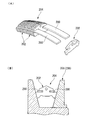
- a steel band (metal band) 200 forming an endless ring (only a part is shown) is provided with a number of steel and plate-like elements (pieces) 202 arranged side by side.
- the belt 204 is endlessly looped around a pair of pulleys (primary pulley 206 and secondary pulley 208) having variable groove widths as shown in FIG. Communicate.
- an input from the engine enters one pulley (primary pulley) 206 and is transmitted to the other pulley (secondary pulley) 208 and then output.
- the effective diameter of each pulley is changed by changing the groove width of each pulley, and the speed change is continuously performed continuously.
- a sliding surface (sheave surface) which forms a groove side surface of a CVT pulley (hereinafter sometimes simply referred to as a pulley) is liable to wear due to frictional contact between the elements at a high surface pressure. Therefore, conventionally, pulleys formed by using a steel type such as JIS SCM420 or the like are subjected to a carburizing and quenching treatment, and a shot peening treatment is added to improve the surface hardness (for example, Patent Document 1 below). reference).
- the shot peening treatment has a problem in that the production cost is high and the shot material used remains on the sliding surface as contamination and damages the sliding surface of the pulley.
- Patent Documents 2 and 3 below use steel materials containing predetermined amounts of Si and Cr to increase the high-temperature tempering hardness on the sliding surface of the pulley. Is disclosed. However, these patent documents do not disclose examples satisfying the chemical composition of the present invention, which is different from the present invention.
- the present invention provides a high surface pressure resistant component capable of improving the wear resistance of a sliding surface to which a high surface pressure is applied without adding a shot peening process, and a method of manufacturing the same. It is done for the purpose of.
- the present invention relates to the following [1] to [3].
- a high surface pressure resistant component characterized in that the surface layer C concentration of the carburized and quenched layer is 0.70 to 0.80% by mass%.
- the steel further contains, by mass%, 0.045 to 0.065% of Nb, 0.030 to 0.047% of Al, and 0.015 to 0.030% of N.
- High surface pressure resistant parts characterized by the following.
- a method for producing a high surface pressure resistant component comprising subjecting a workpiece made of steel having a component composition according to [2] to hot forging and machining to form a predetermined component shape and then carburizing the component.
- the composition of the work material and / or the production conditions are controlled so that the relationship between the effective pinning particle amount X during carburization and the average ferrite average particle size number Y before carburization satisfies the following formula (1).
- the effective pinning particle amount X is a value (ppm) obtained by subtracting the precipitation amounts of NbC and AlN after the hot forging treatment from the precipitation amounts of NbC and AlN after the carburizing treatment.
- a high surface pressure resistant component capable of improving the wear resistance of a sliding surface to which a high surface pressure is applied without adding a shot peening process, and a method of manufacturing the same.
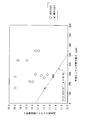
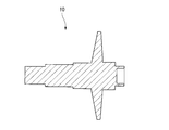
- FIG. 3 is a diagram showing the effect of the effective pinning particle amount X and the average ferrite particle size number Y before carburization on the crystal grain coarsening during carburization. It is explanatory drawing of hot forging and the subsequent rough heat treatment. It is sectional drawing of a test pulley. It is the figure which showed the heat pattern of carburizing hardening process. It is the figure which showed the steel belt of the belt type CVT with the steel band, the element, etc. It is explanatory drawing of a belt type CVT.
- tempering treatment is performed at 300 ° C. for 3 hours. If it is possible to secure the surface hardness of 650 Hv or more later, it is possible to secure the hardness of 650 Hv or more after tempering at 300 ° C. for 3 hours, based on the knowledge that the fatigue life of the sliding surface can be increased. It is a finding of the surface layer C concentration, the amount of Si, and the amount of Cr. ADVANTAGE OF THE INVENTION According to this invention, the abrasion resistance of the sliding surface in a high surface pressure resistant component can be effectively improved without adding a shot peening process.
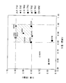
- FIG. 1 is a diagram showing the relationship between the Si content, the Cr content and the surface layer C concentration of the high-pressure resistant surface component of the present invention and the hardness after tempering at 300 ° C. for 3 hours.
- 0.22C-0.73Mn-0.15Cu-0.10Ni is a basic component
- the amount of Si is in the range of 0.55 to 1.05%
- the amount of Cr is 0.55 to 1.00%.
- Steel materials varied in the range were used.
- the history of the test piece is as follows. The hot forged material of the above components is subjected to vacuum carburizing and quenching at 970 ° C. for 150 min and tempering at 130 ° C. for 140 min, and then machined to 10 mm ⁇ 10 mm ⁇ 15 mm, and then further to 300 ° C. After a tempering treatment for 3 hours, the hardness (Hv) of the surface layer was measured.
- the carburizing treatment performed to obtain a predetermined surface layer C concentration is a high-temperature and long-time heat treatment, and there is a concern that austenite crystal grains may be coarsened.
- the presence of abnormally grown grains in the structure due to the coarsening of crystal grains causes a decrease in strength and wear resistance.
- NbC and AlN that have already been precipitated in the state after the hot forging process are coarsened in the subsequent carburizing process and the pinning effect is lost. There is. For this reason, it is effective to increase the effective pinning particle amount by subtracting the NbC and AlN precipitation amounts after the hot forging treatment from the NbC and AlN precipitation amounts after the carburizing treatment.
- FIG. 2 shows the effect of the effective pinning particle amount X and the ferrite grain size number Y before carburizing on the grain size of austenite crystal grains during carburization.
- 0.22C-0.80 to 1.01Si-0.67 to 0.94Mn-0.15Cu-0.10Ni-0.80 to 0.98Cr are used as basic components, and the Nb content is set to 0.031 to A steel material was used in which the Al content was changed in the range of 0.029% to 0.042% and the N content was changed in the range of 0.011 to 0.027% in the range of 0.062%.
- Hot forging was performed on the steel material having the above components under the conditions of 1150 ° C. to 1250 ° C., and the precipitation amounts of NbC and AlN after forging were investigated. Then, it was machined to 10 mm x 10 mm x 15 mm, the ferrite grain size number before carburizing was investigated, vacuum carburizing was performed at 970 ° C for 150 min, the presence or absence of coarsening of old austenite crystal grains, and NbC after carburizing. And the precipitation amount of AlN were investigated.
- the ferrite average grain size number Y before carburization was measured by measuring the ferrite grain size in a 100-fold visual field and 5 visual fields with an optical microscope according to “JIS G0552 Steel ferrite grain size test method”, and these grain size numbers were averaged. Value.
- the old austenite crystal grains were measured according to “JIS G 0551 Steel Austenitic Grain Size Test Method” at 100 times and 5 fields of view under an optical microscope, and based on the following criteria. Has been determined. When the average grain size number of the prior austenite crystal grains was 6 or more and the area ratio of coarse grains (grain size 4.5 or less) in the observed region was less than 20%, it was judged as “ ⁇ ” without coarsening. . On the other hand, when the area ratio of the coarse particles (particle size 4.5 or less) in the observed region is 20% or more, or when there is even a small particle size of 3 or less in the observed region, coarsening occurs. It was judged as "x".
- the ferrite average grain size number Y before carburizing is reduced (the ferrite grain size is increased), and the effective pinning particle amount X Is effective, and the component composition and / or the manufacturing conditions (for example, forging heating) of the workpiece to satisfy the above-mentioned formula (1), ie, Y ⁇ (2.26 ⁇ 10 ⁇ 3 ) X + 10.85. Temperature, forging end temperature, etc.), it is possible to effectively suppress coarsening of crystal grains during carburization.
- One of the features of the present invention is to increase the amount of Si in the steel material in order to enhance the wear resistance.
- scale is easily formed on the surface during hot forging, and scale formation is performed.
- wear of the hot forging die is promoted, and there is a problem that the life of the die is shortened.
- the surface enlargement ratio is 5 or more, the wear of the forging die is remarkable.
- it is effective to lower the forging heating temperature as a measure for extending the mold life. Specifically, by setting the hot heating temperature to 1165 ° C. or lower, mold wear can be effectively suppressed and the mold life can be extended.
- C 0.17 to 0.23%
- C is an element necessary for securing the strength, and is contained in an amount of 0.17% or more to secure the internal hardness of the component.
- the upper limit is made 0.23%.
- it is 0.20 to 0.23%.
- Si 0.80-1.00% Si is an element effective for increasing the high-temperature tempering hardness in the carburized and quenched layer. To obtain this effect, 0.80% or more must be added. However, if the content exceeds 1.00%, the workability decreases, so the upper limit is set to 1.00%. Preferably it is 0.80 to 0.95%.
- Mn 0.65 to 1.00% Mn is added as a deoxidizing agent during melting. Mn is a component useful for securing hardenability, and is contained at 0.65% or more for its function. However, if the content is too large, the machinability may be reduced. Therefore, the upper limit is set to 1.00%. Preferably it is 0.80 to 0.95%.
- P and S are impurities. Since these are elements that are not preferable for the mechanical properties of parts, such as causing embrittlement, the smaller the amount, the better. However, if it is 0.030% or less, there is no appreciable effect on the characteristics. 030%. It is preferable that P and S are not contained, but when they are contained, for example, it may be 0.001 to 0.020%.
- Cu 0.01 to 1.00%
- Cu is an element that improves tensile strength, impact resistance and fatigue strength together with Ni and Cr.
- the reason for setting the lower limit of Cu to 0.01% is that if the content is lower than this, the hardenability decreases and the strength decreases.
- the reason why the upper limit of Cu is set to 1.00% is that if the content of Cu is too large, the workability, particularly the machinability deteriorates.
- it is 0.10 to 0.20%.
- Ni 0.01 to 3.00%
- Ni is an element that improves tensile strength, impact resistance and fatigue strength together with Cu and Cr.
- the reason for setting the lower limit of Ni to 0.01% is that if the content is lower than this, the hardenability decreases and the strength decreases.
- the reason why the upper limit of Ni is set to 3.00% is that if the Ni content is too large, the workability, particularly the machinability deteriorates.
- it is 0.05 to 0.50%.
- Cr 0.80-1.00% Cr is a useful component for enhancing the hardenability and securing the internal hardness, and is contained at 0.80% or more to secure the hardness after tempering at 300 ° C. However, if the content is too large, the machinability may be reduced. Therefore, the upper limit is set to 1.00%. Preferably it is 0.80 to 0.98%.
- the surface layer C concentration 0.70 to 0.80%
- the lower limit of the surface layer C concentration is set to 0.70%.
- the upper limit of the surface layer C concentration is set to 0.80%. Preferably it is 0.75 to 0.80%.
- Nb 0.045 to 0.065% Nb functions to form carbides and pin the austenite grain boundaries during carburization. However, the effect of suppressing crystal grain coarsening is saturated even if the content is excessive, so the upper limit is preferably set to 0.065%. More preferably, it is 0.046 to 0.062%.
- Al 0.030 to 0.047%
- Al reacts with N in steel to form AlN, and has a function of preventing austenite crystal grains from becoming coarse during carburization.
- Al is preferably contained at 0.030% or more.
- the upper limit is preferably set to 0.047%. More preferably, it is 0.033 to 0.042%.
- N 0.015 to 0.030%
- N has a function of reacting with Al in steel to form AlN and preventing coarsening of austenite crystal grains during carburization, and it is preferable to contain 0.015% or more in order to obtain the effect.
- the upper limit is preferably made 0.030%. More preferably, it is 0.018 to 0.027%.
- the high surface pressure part according to the present invention uses a steel having a predetermined composition, and is melted and cast ⁇ high temperature soaking (1300 ° C.) ⁇ slab rolling ⁇ product rolling ⁇ hot forging ⁇ rough heat treatment ⁇ machining ⁇ carburizing and quenching ⁇ It can be manufactured through the manufacturing process of tempering ⁇ finishing machining.
- the workpiece is once heated to a high temperature of 1100 ° C. or higher and then hot forged.
- the material to be forged (worked material) at the time of forging has a significant effect on the underfilling and the forging load.
- Mold wear in hot forging also depends on the deformation resistance of the forged material (work material) during forging, and when the forging heating temperature is low, the deformation resistance of the forged material increases. Accompanying this, the wear amount of the mold also increases. For this reason, the forging heating temperature is preferably set to a temperature higher than 1100 ° C.
- forging heating temperature is high, a large amount of oxide scale is generated, and there is a problem that the mold is damaged, the mold life is shortened, and the productivity is deteriorated. For this reason, the portion where the surface enlargement ratio is 5 or more (the portion where the lubricant applied to the mold surface is greatly elongated and the film of the lubricant formed along the mold surface is likely to be cut).
- forging heating temperature is preferably 1165 ° C. or lower.
- the rough heat treatment is a heat treatment for suppressing the formation of a bainite phase in the structure after forging.
- the suppression of the bainite phase is effective for securing machinability in subsequent machining and preventing coarsening of crystal grains during carburization.
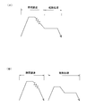
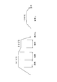
- the rough heat treatment can be performed subsequently to the forging as shown in FIG. In this case, the workpiece is held at a temperature of 640 to 700 ° C. for 30 minutes or more, and then cooled to approximately room temperature.
- the rough heat treatment can be performed on the workpiece once cooled to approximately room temperature.
- the workpiece is held at a temperature of 890 to 950 ° C. for 30 minutes or more, then at a temperature of 640 to 700 ° C. for 30 minutes or more, and cooled to approximately room temperature.
- the “precipitation amount of NbC and AlN after hot forging” required to calculate the above-mentioned effective pinning particle amount X is, as shown in FIG. If performed, it is the amount of precipitation of NbC and AlN after the rough heat treatment. On the other hand, as shown in FIG. 3 (B), when the forging and the rough heat treatment are performed separately, it is the precipitation amount of NbC and AlN after hot forging (before the rough heat treatment).
- test pulley 10 Steel having the chemical composition shown in Table 1 was melted, cast into an ingot, and then subjected to a homogenization treatment of maintaining at 1300 ° C. for 2.5 hours or more. Thereafter, hot forging, rough heat treatment, machining, carburizing and quenching, and tempering were performed to produce a test pulley 10.
- the average particle size number Y of the ferrite before carburizing, the surface layer C concentration (%) after carburizing, and the effective pinning particle amount X (ppm) were investigated. Further, the presence or absence of coarsening of crystal grains in the obtained test pulley 10 was investigated, and further, a tempering treatment was performed at 300 ° C. for 3 hours, and the tempering hardness was investigated.
- the test pulley 10 was charged into an atmospheric furnace (a type in which the furnace temperature was measured and measured with a thermocouple) maintained at 300 ° C., and the temperature was lowered to 300 ° C. at the time of charging and held for 3 hours. .
- ferrite average particle size number before carburization Y For the sliding surface of the test pulley 10 before carburizing (after machining), ferrite crystal grains were measured in a 100-fold visual field and 5 visual fields with an optical microscope according to “JIS G 0552 Ferrite grain size test method for steel”. The average value of the crystal grain size numbers was designated as ferrite average grain size number Y.
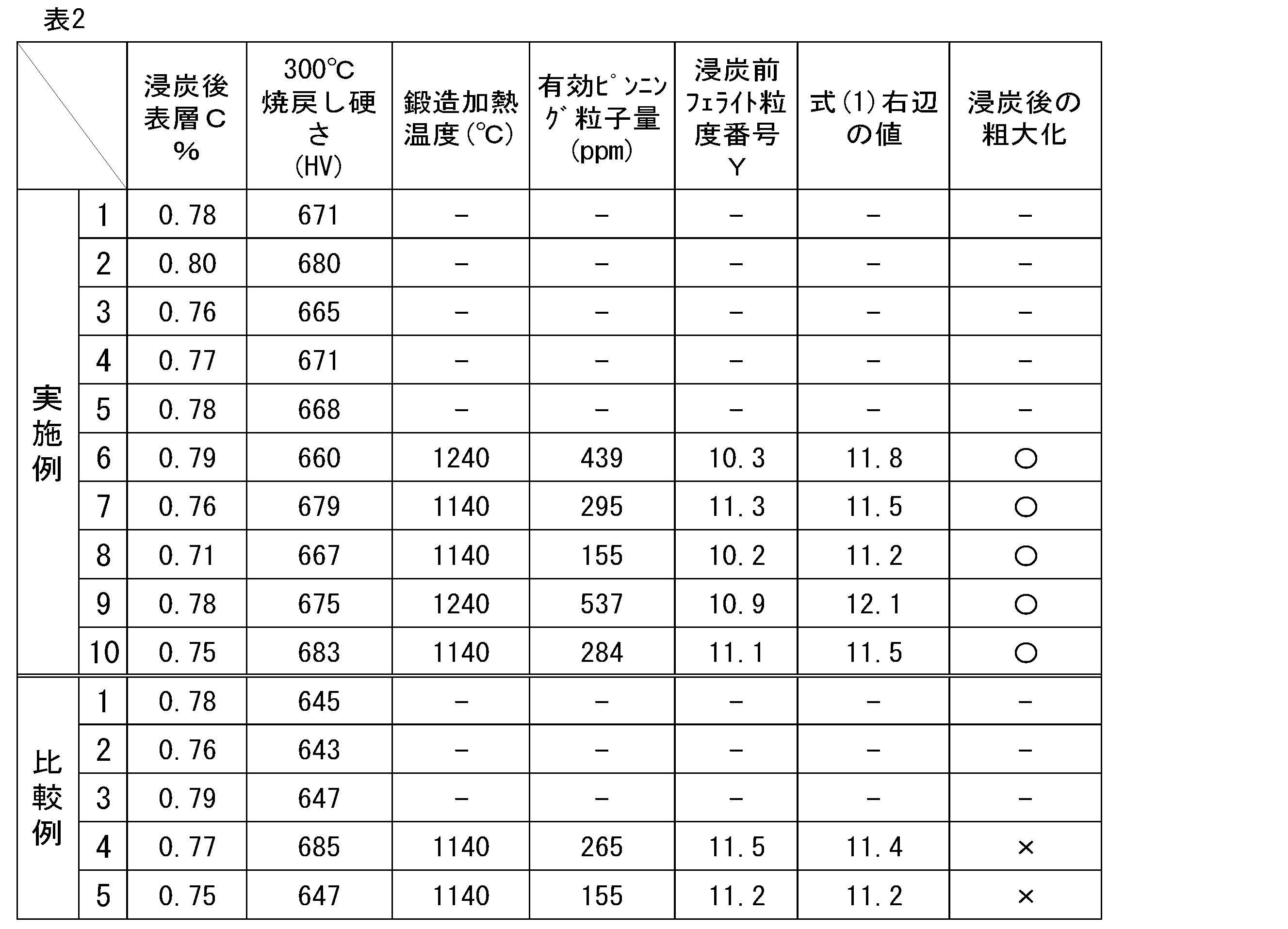
- Comparative Example 1 has a Si content and a Cr content lower than the lower limits of the present invention, and the hardness after tempering at 300 ° C. is lower than the target 650 Hv.
- Comparative Example 2 also has an Si content and a Cr content lower than the lower limits of the present invention, and the hardness after tempering at 300 ° C. is lower than the target 650 Hv.
- Comparative Example 3 the amount of Si is lower than the lower limit of the present invention, and in Comparative Example 3, the hardness after tempering at 300 ° C is lower than the target of 650 Hv.
- Comparative Example 4 the amounts of Si and Cr are within the range of the present invention, and the hardness after tempering at 300 ° C satisfies the target. However, the amounts of Nb and Al added to prevent coarsening are lower than the lower limits of the present invention. Further, in Comparative Example 4, since the forging heating temperature was relatively low at 1140 ° C., the ferrite grain size number Y before carburizing was large (the grain size was small). As a result, the effective pinning particle amount X and the ferrite average grain size number before carburizing were large. The relationship with Y did not satisfy the formula (1) of the present invention, and coarsening of crystal grains was observed in the carburizing treatment.
- Comparative Example 5 the amounts of Si and Cr are lower than the lower limits of the present invention. Therefore, the hardness after tempering at 300 ° C. is lower than the target of 650 Hv. In Comparative Example 5, Nb, Al, and N were added, but the N amount was lower than the lower limit of the present invention. For this reason, the relationship between the effective pinning particle amount X and the ferrite average particle size number Y before carburizing did not satisfy the formula (1) of the present invention, and coarsening of crystal grains was observed in the carburizing treatment.
- a high surface pressure resistant component capable of improving the wear resistance of a sliding surface to which a high surface pressure is applied without adding a shot peening process, and a method of manufacturing the same.
Landscapes
- Chemical & Material Sciences (AREA)
- Engineering & Computer Science (AREA)
- Materials Engineering (AREA)
- Mechanical Engineering (AREA)
- Metallurgy (AREA)
- Organic Chemistry (AREA)
- Thermal Sciences (AREA)
- Crystallography & Structural Chemistry (AREA)
- Physics & Mathematics (AREA)
- Chemical Kinetics & Catalysis (AREA)
- Heat Treatment Of Steel (AREA)
- Heat Treatment Of Articles (AREA)
- Solid-Phase Diffusion Into Metallic Material Surfaces (AREA)
Abstract
Description
その際、各プーリの溝幅を変化させることで各プーリの有効径を変化させ、変速を無段階で連続的に行う。
そこで従来においては、JIS SCM420等の鋼種を用いて構成したプーリに浸炭焼入れ処理を施し、更にショットピーニング処理を追加して表面硬さを向上させたものが用いられていた(例えば下記特許文献1参照)。
[1]
質量%でC:0.17~0.23%、Si:0.80~1.00%、Mn:0.65~1.00%、P:0.030%以下、S:0.030%以下、Cu:0.01~1.00%、Ni:0.01~3.00%、Cr:0.80~1.00%を含有し、残部Fe及び不可避的不純物の組成を有する鋼からなり、浸炭焼入れ層の表層C濃度が質量%で0.70~0.80%であることを特徴とする耐高面圧部品。
[1]において、前記鋼が質量%でNb:0.045~0.065%、Al:0.030~0.047%、N:0.015~0.030%を、更に含有していることを特徴とする耐高面圧部品。
[2]に記載の成分組成の鋼からなる被加工材に、熱間鍛造および機械加工を施し所定の部品形状とした後、浸炭処理を行なう耐高面圧部品の製造方法であって、
浸炭時の有効ピンニング粒子量Xと浸炭前のフェライト平均粒度番号Yとの関係が下記式(1)を満たすように、前記被加工材の成分組成および/または製造条件を制御することを特徴とする耐高面圧部品の製造方法。
Y<(2.26×10⁻³)X+10.85 ・・・式(1)
ここで有効ピンニング粒子量Xは、浸炭処理後のNbCおよびAlNの析出量から熱間鍛造処理後のNbCおよびAlNの析出量を引いた値(ppm)である。
本発明によれば、ショットピーニング処理を付加しなくても、耐高面圧部品における摺動面の耐摩耗性を効果的に高めることができる。
ここでは、0.22C-0.73Mn-0.15Cu-0.10Niを基本成分とし、Si量を0.55~1.05%の範囲で、Cr量を0.55~1.00%の範囲で変化させた鋼材を用いた。
試験片の履歴は以下の通りである。上記成分の熱間鍛造材を970℃、150minの条件での真空浸炭焼入れ、および、130℃、140minの焼戻しの処理を行った後、10mm×10mm×15mmに機械加工を行ない、その後更に300℃、3時間の焼戻し処理を実施し表層の硬さ(Hv)を測定した。
このため本発明では、鋼中にNb-Al-Nを所定量添加することが望ましい。これらの元素により形成される微細な析出物(NbCおよびAlN)のピンニング効果でオーステナイト結晶粒界の移動を抑制し、浸炭時の粒成長を抑制することができるからである。
ここでは、0.22C-0.80~1.01Si-0.67~0.94Mn-0.15Cu-0.10Ni-0.80~0.98Crを基本成分とし、Nb量を0.031~0.062%の範囲で、Al量を0.029~0.042%の範囲で、N量を0.011~0.027%の範囲で変化させた鋼材を用いた。
旧オーステナイト結晶粒の平均粒度番号が6以上で、且つ、観察した領域における粗粒(粒度4.5以下)の面積率が20%未満であった場合、粗大化なしで「○」と判定した。
一方、観察した領域における粗粒(粒度4.5以下)の面積率が20%以上であった場合や、観察した領域中にわずかでも粒度3以下の粗粒があった場合、粗大化ありで「×」と判定した。
このような場合、型寿命を延ばすための方策として鍛造加熱温度を低下させることが有効である。具体的には熱間加熱温度を1165℃以下とすることで型摩耗を効果的に抑制し得て型寿命を延ばすことが可能である。
C:0.17~0.23%
Cは、強度を確保する上で必要な元素であり、部品の内部硬さを確保するために0.17%以上含有させる。但し含有量が多くなると被削性が低下するため、上限を0.23%とする。好ましくは0.20~0.23%である。
Siは、浸炭焼入れ層での高温焼戻し硬さを高めるために有効な元素である。この効果を得るために0.80%以上の添加が必要である。ただし、1.00%を超えて含有させると加工性が低下するため、上限を1.00%とする。好ましくは0.80~0.95%である。
Mnは溶製時の脱酸剤として添加される。Mnは焼入れ性を確保する上で有用な成分であり、その働きのために0.65%以上含有させる。但し、含有量が多くなり過ぎると被削性の低下が懸念されるため、上限を1.00%とする。好ましくは0.80~0.95%である。
PおよびSは、不純物である。これらは脆化を招くなど、部品の機械的性質にとって好ましくない元素であるため、その量は少ないほうが好ましいが、0.030%以下であれば特性にそれ程の影響がなく、その上限を0.030%とする。PおよびSを含有しないことが好ましいが、含有する場合は、例えば、0.001~0.020%であってもよい。
Cuは、Ni,Crと共に引張強度、耐衝撃値および疲労強度を向上させる元素である。Cuの下限を0.01%としたのは、これよりも含有量が少ないと焼入れ性が低下し、強度が低下するためである。一方、Cuの上限を1.00%としたのはCuが多すぎると加工性、特に被削性が劣化するためである。好ましくは0.10~0.20%である。
Niは、Cu,Crと共に引張強度、耐衝撃値および疲労強度を向上させる元素である。Niの下限を0.01%としたのは、これよりも含有量が少ないと焼入れ性が低下し、強度が低下するためである。一方、Niの上限を3.00%としたのはNiが多すぎると加工性、特に被削性が劣化するためである。好ましくは0.05~0.50%である。
Crは焼入れ性を高めて内部硬度を確保する上で有用な成分であり、300℃焼戻し後の硬さを確保するために0.80%以上含有させる。但し、含有量が多くなり過ぎると被削性の低下が懸念されるため、上限を1.00%とする。好ましくは0.80~0.98%である。
所定の熱処理後硬さを維持するためには、表層C濃度が0.70%以上必要であるため、表層C濃度の下限を0.70%に規定した。一方、表層C濃度が0.80%を超えると、大型の炭化物が生成し、耐摩耗性が低下する虞があるため、表層C濃度の上限を0.80%とした。好ましくは0.75~0.80%である。
Nbは、炭化物を形成して浸炭時のオーステナイト粒界をピン止めする働きがある。但し、過大に含有しても結晶粒粗大化を抑制する効果が飽和してしまうので、その上限を0.065%とすることが好ましい。より好ましくは0.046~0.062%である。
Alは、鋼中のNと反応してAlNを形成し、浸炭時のオーステナイト結晶粒の粗大化を防止する働きがあり、その効果を得るためには0.030%以上含有させることが好ましい。但し、過大に含有しても結晶粒粗大化を抑制する効果が飽和してしまうため、上限を0.047%とすることが好ましい。より好ましくは0.033~0.042%である。
Nは、鋼中のAlと反応してAlNを形成し、浸炭時のオーステナイト結晶粒の粗大化を防止する働きがあり、その効果を得るためには0.015%以上含有させることが好ましい。但し、過大に含有しても結晶粒粗大化を抑制する効果が飽和するとともに、窒化物が増加して強度低下の原因となるため、その上限を0.030%とすることが好ましい。より好ましくは0.018~0.027%である。
粗熱処理は、図3(A)に示すように、鍛造加工後、引き続いて実施することができる。この場合、被加工材を640~700℃の温度で30分以上保持し、その後に略室温までの冷却を行う。
一方、図3(B)に示すように、鍛造加工と粗熱処理と分けて実施する場合、熱間鍛造後(粗熱処理前)におけるNbCおよびAlNの析出量である。

試験用プーリ10の製造過程で浸炭前フェライト平均粒度番号Y、浸炭後の表層C濃度(%)、有効ピンニング粒子量X(ppm)を調査した。また得られた試験用プーリ10における結晶粒粗大化の有無を調査し、更に300℃、3時間の焼戻し処理を実施し、焼戻し硬さを調査した。これらの結果が下記表2に示してある。
被加工材を表2で示す鍛造加熱温度に加熱した後、被加工材の略上半部、下半部をそれぞれ上型、下型の凹部内に挿入して所定の形状に成形した。その後、熱間鍛造に引き続いて被加工材を640~700℃の温度で30分以上保持し、その後に略室温まで冷却を行う粗熱処理(図3(A)参照)を実施した。
真空浸炭炉を用い、図5に示すヒートパターンで、浸炭温度970℃で2.5時間保持し、次いで浸炭温度890℃で0.5時間保持した後に、80℃の油で焼き入れする浸炭焼入れ処理を施した。焼戻しは130℃で1.5時間保持し、空冷することにより行った。
300℃に保持された大気炉(炉温を熱電対にて実測しながら制御するタイプ)に試験用プーリ10を投入し、投入時に低下した温度が300℃に戻ってから3時間保持を実施した。
試験用プーリ10の摺動面を埋め込んで研磨仕上げし、表層部のC濃度を電子プローブマイクロアナライザー(Electron Probe Micro Analyzer;EPMA)により分析した。
JIS Z 2244に従い、試験用プーリ10の摺動面を鏡面研摩し、表面から50μmの位置を荷重2.94Nで測定した値を用いた。
鍛造処理後および浸炭処理後、試験用プーリ10の摺動面において抽出分析(臭素メタノール法、電界抽出法)を実施し、NbC抽出量およびAlN抽出量を定量分析し、NbCおよびAlNの析出量を求めた。そして浸炭処理後のNbCおよびAlNの析出量から熱間鍛造処理後のNbCおよびAlNの析出量を引いた値(ppm)を有効ピンニング粒子量Xとした。
浸炭前(機械加工後)の試験用プーリ10の摺動面について、光学顕微鏡の100倍視野且つ5視野でのフェライト結晶粒を「JIS G 0552 鋼のフェライト結晶粒度試験方法」に準じて測定し、それら結晶粒度番号の平均値をフェライト平均粒度番号Yとした。
浸炭処理後の試験用プーリ10の摺動面について、光学顕微鏡の100倍視野且つ5視野での旧オーステナイト結晶粒を「JIS G 0551 鋼のオーステナイト結晶粒度試験方法」に準じて測定し、段落0021に記載した基準に基づいて結晶粒粗大化の有無を評価した。
200 スチールバンド(金属バンド)
202 エレメント(駒)
204 スチールベルト
206 プライマリプーリ
208 セカンダリプーリ
Claims (3)
- 質量%で
C:0.17~0.23%
Si:0.80~1.00%
Mn:0.65~1.00%
P:0.030%以下
S:0.030%以下
Cu:0.01~1.00%
Ni:0.01~3.00%
Cr:0.80~1.00%
を含有し、残部Fe及び不可避的不純物の組成を有する鋼からなり、浸炭焼入れ層の表層C濃度が質量%で0.70~0.80%であることを特徴とする耐高面圧部品。 - 請求項1において、前記鋼が質量%で
Nb:0.045~0.065%
Al:0.030~0.047%
N:0.015~0.030%
を更に含有していることを特徴とする耐高面圧部品。 - 請求項2に記載の成分組成の鋼からなる被加工材に、熱間鍛造および機械加工を施し所定の部品形状とした後、浸炭処理を行なう耐高面圧部品の製造方法であって、
浸炭時の有効ピンニング粒子量Xと浸炭前のフェライト平均粒度番号Yとの関係が下記式(1)を満たすように、前記被加工材の成分組成および/または製造条件を制御することを特徴とする耐高面圧部品の製造方法。
Y<(2.26×10⁻³)X+10.85 ・・・式(1)
ここで有効ピンニング粒子量Xは、浸炭処理後のNbCおよびAlNの析出量から熱間鍛造処理後のNbCおよびAlNの析出量を引いた値であり、単位をppmとした場合の値である。
Priority Applications (3)
| Application Number | Priority Date | Filing Date | Title |
|---|---|---|---|
| US17/275,123 US12129557B2 (en) | 2018-09-12 | 2019-09-03 | High surface-pressure resistant component and production method therefor |
| MX2021002917A MX2021002917A (es) | 2018-09-12 | 2019-09-03 | Componente resistente a alta presion superficial y metodo de produccion del mismo. |
| CN201980059607.8A CN112689686B (zh) | 2018-09-12 | 2019-09-03 | 耐高表面压部件及其制造方法 |
Applications Claiming Priority (2)
| Application Number | Priority Date | Filing Date | Title |
|---|---|---|---|
| JP2018170941A JP7154073B2 (ja) | 2018-09-12 | 2018-09-12 | 耐高面圧部品およびその製造方法 |
| JP2018-170941 | 2018-09-12 |
Publications (1)
| Publication Number | Publication Date |
|---|---|
| WO2020054522A1 true WO2020054522A1 (ja) | 2020-03-19 |
Family
ID=69777629
Family Applications (1)
| Application Number | Title | Priority Date | Filing Date |
|---|---|---|---|
| PCT/JP2019/034668 Ceased WO2020054522A1 (ja) | 2018-09-12 | 2019-09-03 | 耐高面圧部品およびその製造方法 |
Country Status (5)
| Country | Link |
|---|---|
| US (1) | US12129557B2 (ja) |
| JP (1) | JP7154073B2 (ja) |
| CN (1) | CN112689686B (ja) |
| MX (1) | MX2021002917A (ja) |
| WO (1) | WO2020054522A1 (ja) |
Citations (4)
| Publication number | Priority date | Publication date | Assignee | Title |
|---|---|---|---|---|
| JP2008195997A (ja) * | 2007-02-09 | 2008-08-28 | Daido Steel Co Ltd | 低歪真空浸炭ガス焼入れ用鋼およびそれから製造した低歪浸炭部品 |
| JP2012117102A (ja) * | 2010-11-30 | 2012-06-21 | Kobe Steel Ltd | 肌焼鋼、およびこれを用いた機械構造部品 |
| JP2013122286A (ja) * | 2011-12-12 | 2013-06-20 | Jatco Ltd | 無段変速機用プーリ及び無段変速機 |
| JP2014070256A (ja) * | 2012-09-28 | 2014-04-21 | Daido Steel Co Ltd | 耐高面圧部品 |
Family Cites Families (7)
| Publication number | Priority date | Publication date | Assignee | Title |
|---|---|---|---|---|
| CA2137744C (en) | 1994-02-03 | 1999-08-31 | Kazuo Sakamoto | Steel for carburized gear |
| JP5018586B2 (ja) | 2007-04-09 | 2012-09-05 | 大同特殊鋼株式会社 | 高強度浸炭高周波焼入れ部品 |
| JP4938603B2 (ja) | 2007-09-13 | 2012-05-23 | トヨタ自動車株式会社 | 無段変速機用プーリー及び無段変速機 |
| WO2010137607A1 (ja) | 2009-05-27 | 2010-12-02 | 住友金属工業株式会社 | 浸炭部品およびその製造方法 |
| JP5897975B2 (ja) | 2012-04-25 | 2016-04-06 | 本田技研工業株式会社 | ベルト式cvtのプーリー用鋼及びベルト式cvtプーリー |
| CN104583438B (zh) | 2012-09-03 | 2016-10-12 | 新日铁住金株式会社 | 渗碳部件 |
| JP6967337B2 (ja) * | 2015-03-31 | 2021-11-17 | 日本製鉄株式会社 | 浸炭窒化部品および浸炭窒化部品の製造方法 |
-
2018
- 2018-09-12 JP JP2018170941A patent/JP7154073B2/ja active Active
-
2019
- 2019-09-03 CN CN201980059607.8A patent/CN112689686B/zh active Active
- 2019-09-03 MX MX2021002917A patent/MX2021002917A/es unknown
- 2019-09-03 US US17/275,123 patent/US12129557B2/en active Active
- 2019-09-03 WO PCT/JP2019/034668 patent/WO2020054522A1/ja not_active Ceased
Patent Citations (4)
| Publication number | Priority date | Publication date | Assignee | Title |
|---|---|---|---|---|
| JP2008195997A (ja) * | 2007-02-09 | 2008-08-28 | Daido Steel Co Ltd | 低歪真空浸炭ガス焼入れ用鋼およびそれから製造した低歪浸炭部品 |
| JP2012117102A (ja) * | 2010-11-30 | 2012-06-21 | Kobe Steel Ltd | 肌焼鋼、およびこれを用いた機械構造部品 |
| JP2013122286A (ja) * | 2011-12-12 | 2013-06-20 | Jatco Ltd | 無段変速機用プーリ及び無段変速機 |
| JP2014070256A (ja) * | 2012-09-28 | 2014-04-21 | Daido Steel Co Ltd | 耐高面圧部品 |
Also Published As
| Publication number | Publication date |
|---|---|
| MX2021002917A (es) | 2021-06-15 |
| JP2020041199A (ja) | 2020-03-19 |
| US12129557B2 (en) | 2024-10-29 |
| US20220049341A1 (en) | 2022-02-17 |
| CN112689686A (zh) | 2021-04-20 |
| CN112689686B (zh) | 2022-08-30 |
| JP7154073B2 (ja) | 2022-10-17 |
Similar Documents
| Publication | Publication Date | Title |
|---|---|---|
| JP4872846B2 (ja) | 窒化歯車用粗形品および窒化歯車 | |
| JP2007162128A (ja) | 鍛造性と結晶粒粗大化防止特性に優れた肌焼鋼およびその製造方法並びに浸炭部品 | |
| CN103348031A (zh) | 氮化用钢以及氮化部件 | |
| JP5897975B2 (ja) | ベルト式cvtのプーリー用鋼及びベルト式cvtプーリー | |
| CN104302799B (zh) | 表面渗碳用钢钢材 | |
| JP6578651B2 (ja) | 耐摩耗性に優れた浸炭部材及びその製造方法 | |
| WO2017170540A1 (ja) | 面疲労強度および曲げ疲労強度に優れた浸炭窒化部品、並びにその製造方法 | |
| JP5683348B2 (ja) | 浸炭部材、浸炭部材用鋼および浸炭部材の製造方法 | |
| TWI544088B (zh) | Vacuum carburizing steel and its manufacturing method | |
| JP7013833B2 (ja) | 浸炭部品 | |
| TWI630278B (zh) | Surface hardened steel | |
| JP7154073B2 (ja) | 耐高面圧部品およびその製造方法 | |
| JP2016222982A (ja) | 耐ピッチング特性に優れる機械構造用肌焼鋼及び機械構造用部品素材 | |
| JP6160054B2 (ja) | 耐高面圧部品 | |
| TWI609090B (zh) | 滲碳用鋼材及滲碳元件 | |
| JP7063070B2 (ja) | 浸炭部品 | |
| JP5821512B2 (ja) | 窒化部品およびその製造方法 | |
| US11326244B2 (en) | Steel material for CVT sheave, CVT sheave, and method for manufacturing CVT sheave | |
| JP2018172751A (ja) | 窒化用cvtリング素材、cvtリング部材及びこれらの製造方法 | |
| WO2016158375A1 (ja) | 浸炭窒化用鋼材および浸炭窒化部品 | |
| JP7063071B2 (ja) | 浸炭部品 | |
| JP2018172754A (ja) | 窒化用cvtリング素材、cvtリング部材及びこれらの製造方法 | |
| JP7156021B2 (ja) | 浸炭鋼部品用鋼材 | |
| JP2024152304A (ja) | 窒化用鋼および浸硫窒化部品 | |
| JP2024152306A (ja) | 酸窒化用鋼および酸窒化部品 |
Legal Events
| Date | Code | Title | Description |
|---|---|---|---|
| 121 | Ep: the epo has been informed by wipo that ep was designated in this application |
Ref document number: 19860268 Country of ref document: EP Kind code of ref document: A1 |
|
| WWE | Wipo information: entry into national phase |
Ref document number: MX/A/2021/002917 Country of ref document: MX |
|
| NENP | Non-entry into the national phase |
Ref country code: DE |
|
| WWP | Wipo information: published in national office |
Ref document number: MX/A/2021/002917 Country of ref document: MX |
|
| 122 | Ep: pct application non-entry in european phase |
Ref document number: 19860268 Country of ref document: EP Kind code of ref document: A1 |
|
| WWG | Wipo information: grant in national office |
Ref document number: MX/A/2021/002917 Country of ref document: MX |