WO2020054027A1 - ステント - Google Patents
ステント Download PDFInfo
- Publication number
- WO2020054027A1 WO2020054027A1 PCT/JP2018/034005 JP2018034005W WO2020054027A1 WO 2020054027 A1 WO2020054027 A1 WO 2020054027A1 JP 2018034005 W JP2018034005 W JP 2018034005W WO 2020054027 A1 WO2020054027 A1 WO 2020054027A1
- Authority
- WO
- WIPO (PCT)
- Prior art keywords
- folded
- stent
- intersection
- wire
- vertical
- Prior art date
- Legal status (The legal status is an assumption and is not a legal conclusion. Google has not performed a legal analysis and makes no representation as to the accuracy of the status listed.)
- Ceased
Links
Images


Classifications
-
- A—HUMAN NECESSITIES
- A61—MEDICAL OR VETERINARY SCIENCE; HYGIENE
- A61F—FILTERS IMPLANTABLE INTO BLOOD VESSELS; PROSTHESES; DEVICES PROVIDING PATENCY TO, OR PREVENTING COLLAPSING OF, TUBULAR STRUCTURES OF THE BODY, e.g. STENTS; ORTHOPAEDIC, NURSING OR CONTRACEPTIVE DEVICES; FOMENTATION; TREATMENT OR PROTECTION OF EYES OR EARS; BANDAGES, DRESSINGS OR ABSORBENT PADS; FIRST-AID KITS
- A61F2/00—Filters implantable into blood vessels; Prostheses, i.e. artificial substitutes or replacements for parts of the body; Appliances for connecting them with the body; Devices providing patency to, or preventing collapsing of, tubular structures of the body, e.g. stents
- A61F2/82—Devices providing patency to, or preventing collapsing of, tubular structures of the body, e.g. stents
- A61F2/86—Stents in a form characterised by the wire-like elements; Stents in the form characterised by a net-like or mesh-like structure
- A61F2/90—Stents in a form characterised by the wire-like elements; Stents in the form characterised by a net-like or mesh-like structure characterised by a net-like or mesh-like structure
-
- A—HUMAN NECESSITIES
- A61—MEDICAL OR VETERINARY SCIENCE; HYGIENE
- A61F—FILTERS IMPLANTABLE INTO BLOOD VESSELS; PROSTHESES; DEVICES PROVIDING PATENCY TO, OR PREVENTING COLLAPSING OF, TUBULAR STRUCTURES OF THE BODY, e.g. STENTS; ORTHOPAEDIC, NURSING OR CONTRACEPTIVE DEVICES; FOMENTATION; TREATMENT OR PROTECTION OF EYES OR EARS; BANDAGES, DRESSINGS OR ABSORBENT PADS; FIRST-AID KITS
- A61F2/00—Filters implantable into blood vessels; Prostheses, i.e. artificial substitutes or replacements for parts of the body; Appliances for connecting them with the body; Devices providing patency to, or preventing collapsing of, tubular structures of the body, e.g. stents
- A61F2/82—Devices providing patency to, or preventing collapsing of, tubular structures of the body, e.g. stents
- A61F2/86—Stents in a form characterised by the wire-like elements; Stents in the form characterised by a net-like or mesh-like structure
-
- A—HUMAN NECESSITIES
- A61—MEDICAL OR VETERINARY SCIENCE; HYGIENE
- A61F—FILTERS IMPLANTABLE INTO BLOOD VESSELS; PROSTHESES; DEVICES PROVIDING PATENCY TO, OR PREVENTING COLLAPSING OF, TUBULAR STRUCTURES OF THE BODY, e.g. STENTS; ORTHOPAEDIC, NURSING OR CONTRACEPTIVE DEVICES; FOMENTATION; TREATMENT OR PROTECTION OF EYES OR EARS; BANDAGES, DRESSINGS OR ABSORBENT PADS; FIRST-AID KITS
- A61F2/00—Filters implantable into blood vessels; Prostheses, i.e. artificial substitutes or replacements for parts of the body; Appliances for connecting them with the body; Devices providing patency to, or preventing collapsing of, tubular structures of the body, e.g. stents
- A61F2/82—Devices providing patency to, or preventing collapsing of, tubular structures of the body, e.g. stents
- A61F2/86—Stents in a form characterised by the wire-like elements; Stents in the form characterised by a net-like or mesh-like structure
- A61F2/89—Stents in a form characterised by the wire-like elements; Stents in the form characterised by a net-like or mesh-like structure the wire-like elements comprising two or more adjacent rings flexibly connected by separate members
-
- A—HUMAN NECESSITIES
- A61—MEDICAL OR VETERINARY SCIENCE; HYGIENE
- A61F—FILTERS IMPLANTABLE INTO BLOOD VESSELS; PROSTHESES; DEVICES PROVIDING PATENCY TO, OR PREVENTING COLLAPSING OF, TUBULAR STRUCTURES OF THE BODY, e.g. STENTS; ORTHOPAEDIC, NURSING OR CONTRACEPTIVE DEVICES; FOMENTATION; TREATMENT OR PROTECTION OF EYES OR EARS; BANDAGES, DRESSINGS OR ABSORBENT PADS; FIRST-AID KITS
- A61F2/00—Filters implantable into blood vessels; Prostheses, i.e. artificial substitutes or replacements for parts of the body; Appliances for connecting them with the body; Devices providing patency to, or preventing collapsing of, tubular structures of the body, e.g. stents
- A61F2/02—Prostheses implantable into the body
- A61F2/04—Hollow or tubular parts of organs, e.g. bladders, tracheae, bronchi or bile ducts
- A61F2002/041—Bile ducts
-
- A—HUMAN NECESSITIES
- A61—MEDICAL OR VETERINARY SCIENCE; HYGIENE
- A61F—FILTERS IMPLANTABLE INTO BLOOD VESSELS; PROSTHESES; DEVICES PROVIDING PATENCY TO, OR PREVENTING COLLAPSING OF, TUBULAR STRUCTURES OF THE BODY, e.g. STENTS; ORTHOPAEDIC, NURSING OR CONTRACEPTIVE DEVICES; FOMENTATION; TREATMENT OR PROTECTION OF EYES OR EARS; BANDAGES, DRESSINGS OR ABSORBENT PADS; FIRST-AID KITS
- A61F2/00—Filters implantable into blood vessels; Prostheses, i.e. artificial substitutes or replacements for parts of the body; Appliances for connecting them with the body; Devices providing patency to, or preventing collapsing of, tubular structures of the body, e.g. stents
- A61F2/02—Prostheses implantable into the body
- A61F2/04—Hollow or tubular parts of organs, e.g. bladders, tracheae, bronchi or bile ducts
- A61F2002/044—Oesophagi or esophagi or gullets
-
- A—HUMAN NECESSITIES
- A61—MEDICAL OR VETERINARY SCIENCE; HYGIENE
- A61F—FILTERS IMPLANTABLE INTO BLOOD VESSELS; PROSTHESES; DEVICES PROVIDING PATENCY TO, OR PREVENTING COLLAPSING OF, TUBULAR STRUCTURES OF THE BODY, e.g. STENTS; ORTHOPAEDIC, NURSING OR CONTRACEPTIVE DEVICES; FOMENTATION; TREATMENT OR PROTECTION OF EYES OR EARS; BANDAGES, DRESSINGS OR ABSORBENT PADS; FIRST-AID KITS
- A61F2/00—Filters implantable into blood vessels; Prostheses, i.e. artificial substitutes or replacements for parts of the body; Appliances for connecting them with the body; Devices providing patency to, or preventing collapsing of, tubular structures of the body, e.g. stents
- A61F2/02—Prostheses implantable into the body
- A61F2/04—Hollow or tubular parts of organs, e.g. bladders, tracheae, bronchi or bile ducts
- A61F2002/045—Stomach, intestines
-
- A—HUMAN NECESSITIES
- A61—MEDICAL OR VETERINARY SCIENCE; HYGIENE
- A61F—FILTERS IMPLANTABLE INTO BLOOD VESSELS; PROSTHESES; DEVICES PROVIDING PATENCY TO, OR PREVENTING COLLAPSING OF, TUBULAR STRUCTURES OF THE BODY, e.g. STENTS; ORTHOPAEDIC, NURSING OR CONTRACEPTIVE DEVICES; FOMENTATION; TREATMENT OR PROTECTION OF EYES OR EARS; BANDAGES, DRESSINGS OR ABSORBENT PADS; FIRST-AID KITS
- A61F2240/00—Manufacturing or designing of prostheses classified in groups A61F2/00 - A61F2/26 or A61F2/82 or A61F9/00 or A61F11/00 or subgroups thereof
- A61F2240/001—Designing or manufacturing processes
Definitions
- stent placement has been used in which a stent made of a wire (element wire) or the like is placed in an affected area where stenosis or occlusion has occurred in a lumen of a tubular organ in a living body, thereby expanding and holding the lumen of the tubular organ. Have been.
- a self-expanding stent (self-expandable stent) is delivered to a diseased site where stenosis or occlusion has occurred in a reduced diameter state by a delivery system.
- the stent released from the delivery system expands stenosis and occlusion by expanding its diameter by self-expanding.
- the stent Since the lumen in which such a stent is to be placed is often bent, the stent needs to have a function of maintaining a shape conforming to the shape of the bent lumen (a channel shape maintaining function). When the stent having the duct shape maintaining function is placed in a bent lumen, the stent can maintain a shape conforming to the shape of the bent lumen without returning to the original shape of the stent due to a reaction force.
- the expansion mechanism using the shape memory alloy described in Patent Document 1 can expand a stenosis part of the body. Further, the expansion mechanism described in Patent Literature 1 has an “engaging portion” that can expand and contract in the axial direction, and maintains a shape that matches the shape of the lumen regardless of the lumen shape of the stenosis portion. Can be.
- the extensible “meshing portion” is formed by folding the wires from different positions in the longitudinal direction, folding the wires, and hanging the wires.
- the extendable “meshing portion” is formed by folding the wires from different positions in the longitudinal direction, folding the wires, and hanging the wires.
- an object of the present invention is to provide a stent that has a high degree of freedom in designing the arrangement of expandable portions in a stent woven by crossing wires.
- the stent according to the first aspect of the present invention is a tubular stent woven by crossing wires, wherein the wires are folded back in the axial direction and cross each other, and the wires are circumferentially crossed with each other. A vertical folded intersection that folds back and crosses in the direction.
- the stent of the present invention has a high degree of design freedom regarding the arrangement of expandable and contractible portions in a stent woven with wires crossed.
- FIG. 3 is a development view in which the stent is developed in a circumferential direction. It is a figure showing the same stent bent.
- FIG. 4 shows the stent when released from the delivery system. It is a figure showing the modification of the vertical turn intersection part of the same stent. It is a figure showing the modification of the vertical turn intersection part of the same stent. It is a figure showing the modification of the vertical turn intersection part of the same stent. It is a figure showing the modification of the vertical turn intersection part of the same stent. It is a figure showing the modification of the vertical turn intersection part of the same stent. It is the development view which developed the stent concerning a second embodiment of the present invention in the peripheral direction. It is the development view which expanded the modification of the same stent to the peripheral direction.
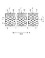
- FIG. 1 is a diagram showing an overall configuration of a stent 100 according to the present embodiment.
- FIG. 1 shows the entire configuration of the stent 100 in a self-expanded state.
- the stent 100 is formed by weaving the wire W and has a cylindrical shape.
- the stent 100 has a self-expanding property, is placed in a lumen of a digestive system body such as a bile duct, an esophagus, a duodenum, a small intestine, and a large intestine, and is mainly used for expanding and maintaining the lumen.
- the stent 100 of the present embodiment is not a so-called covered stent whose outer peripheral surface is covered with a resin film or the like, but is an uncovered stent not covered with a film or the like.
- the stent 100 can be covered with a resin film or the like and used as a covered stent.
- the stent 100 includes a tubular portion 1 and a connecting portion 2 as shown in FIG.
- the tubular portions 1 and the connecting portions 2 are alternately arranged in a longitudinal axis direction (hereinafter, referred to as “axial direction”).
- axial direction a longitudinal axis direction
- first axial direction D1 first axial direction
- second axial direction D2 second axial direction
- first circumferential direction R1 first circumferential direction
- second circumferential direction R2 One of the circumferential directions of the stent 100 is referred to as “first circumferential direction R1”
- second circumferential direction R2 is referred to as “second circumferential direction R2”.
- the wire W forms an intersection 3 where different portions of the wire W cross each other.
- the intersection 3 has a horizontal folded intersection 31, a vertical folded intersection 32, and a straight intersection 33 where different portions of the wire intersect straight.
- the tubular portion 1 is formed by knitting the wire W into a tubular shape having a mesh on the peripheral surface.
- the tubular portion 1 has a vertically folded intersection 32 and a straight intersection 33.
- the connecting portion 2 has a horizontal folded intersection 31 and a vertical folded intersection 32.
- the horizontal folded intersections 31 and the vertical folded intersections 32 are arranged in the circumferential direction.
- one connecting portion 2 has seven horizontal folded intersections 31 and one vertical folded intersection 32.
- the horizontal folded portion 31 is formed by different portions of the wire W (hereinafter, referred to as “first horizontal folded portion 31a” and “second horizontal folded portion 31b”) that are folded back in the axial direction and cross each other. It can expand and contract in the axial direction.
- the first laterally folded portion 31a is a convex portion in which the wire W extending inclining in the circumferential direction is folded and bent in the axial direction to be convex in the first axial direction D1.
- the second laterally folded portion 31b is a convex portion in which the wire W extending inclining in the circumferential direction is folded and bent in the axial direction to be convex in the second axial direction D2.
- the first horizontal folded portion 31a and the second horizontal folded portion 31b intersect in a “hook shape” in the radial direction, and are connected so as to be relatively movable although they cannot be separated.
- the vertical folded intersection 32 is formed by crossing different portions of the wire W (hereinafter, referred to as “first vertical folded portion 32a” and “second vertical folded portion 32b”) in a circumferential direction with respect to each other. It can expand and contract in the circumferential direction.
- the first vertical folded portion 32a is a convex portion in which the wire W extending inclining in the axial direction is bent by bending in the circumferential direction to be bent toward the first circumferential direction R1.
- the second vertical folded portion 32b is a convex portion in which the wire W extending inclining in the axial direction is bent in the circumferential direction by bending and bending toward the second circumferential direction R2.
- the first vertically folded portion 32a and the second vertically folded portion 32b intersect in a "hook shape" in the radial direction, and are connected to each other so as to be inseparable but relatively movable.
- the straight crossing portion 33 is formed by wires W that extend obliquely in both the circumferential direction and the axial direction intersect each other without being folded back. At the straight intersections 33 that are continuous along the wires W, the wires W alternately pass radially outside and radially inside of the intersecting wires W.
- the straight intersecting portion 33 thus woven has a repulsive force against expansion and contraction in the axial direction and the circumferential direction.
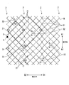
- FIG. 2 is a development view in which the stent 100 is developed in the circumferential direction.
- the wire W forming the stent 100 extends from the start position S in a direction inclined in both the circumferential direction and the axial direction (hereinafter, referred to as an “oblique direction”), A folded intersection 31 and a vertically folded intersection 32 are formed.
- the wire W extends obliquely from the start position S, and forms one of the intersecting wires W at five continuous straight intersections 33. Thereafter, the wire W constitutes one of the intersecting wires W at the laterally folded intersection 31 of the connecting portion 2 (the portion 1 shown in FIG. 2).
- the wire W folded back in the axial direction at the connecting portion 2 extends in an oblique direction, and forms one of the intersecting wires W at five continuous straight intersections 33. Thereafter, the wire W constitutes one of the intersecting wires W at the laterally folded intersection 31 of the connecting portion 2 (portion 2 shown in FIG. 2).
- the wire W folded back in the axial direction at the connecting portion 2 extends in an oblique direction, and forms one of the intersecting wires W at five continuous straight intersections 33. Thereafter, the wire W constitutes one of the intersecting wires W at the laterally folded intersection 31 of the connecting portion 2 (portion 3 shown in FIG. 2).
- the wire W folded back in the axial direction at the connecting portion 2 extends in an oblique direction, and forms one of the intersecting wires W at two continuous straight intersections 33. Thereafter, the wire W forms one of the intersecting wires W at the vertically folded intersection 32 (portion 4 shown in FIG. 2).
- the wire W folded in the circumferential direction at the vertical folded intersection 32 extends in an oblique direction and forms one of the intersecting wires W at two continuous straight intersections 33. Thereafter, the wire W constitutes one of the intersecting wires W at the laterally folded intersection 31 of the connecting portion 2 (portion 5 shown in FIG. 2).
- the wire W folded back in the axial direction at the connecting portion 2 extends in an oblique direction, and forms one of the intersecting wires W at five continuous straight intersections 33. Thereafter, the wire W forms one of the intersecting wires W at the vertically folded intersection 32 of the connecting portion 2 (portion 6 shown in FIG. 2).
- the wire W constitutes one of the intersecting wires W in the vertically folded intersection portion 32 in the connecting portion 2, so that the tubular portions 1 adjacent to each other across the connecting portion 2 can be continuously woven without being cut. .
- the wire W folded in the circumferential direction at the vertically folded intersection 32 of the connecting portion 2 extends in an oblique direction and forms one of the intersecting wires W at five continuous straight intersections 33. Thereafter, the wire W constitutes one of the intersecting wires W at the horizontal folded intersection 31 of the connecting portion 2 (the portion 7 shown in FIG. 2).
- the wire W folded back in the axial direction at the connecting portion 2 extends in an oblique direction, and forms one of the intersecting wires W at five continuous straight intersections 33. Thereafter, the wire W constitutes one of the intersecting wires W at the laterally folded intersection 31 of the connecting portion 2 (the portion 8 shown in FIG. 2).
- the wire W forms other horizontal folded intersections 31, vertical folded intersections 32, and straight intersections 33 by the same method, and is woven to the end point E without being cut.
- the wire W is a superelastic alloy mainly composed of NiTi.
- the superelastic alloy containing NiTi as a main material does not undergo permanent deformation at the time of braiding, and the braided shape is memorized by applying heat treatment in the braided state.
- the stent 100 is stored in a delivery system in a reduced diameter state, and is conveyed to an affected area where stenosis or occlusion has occurred.
- the stent 100 released from the delivery system expands stenosis and occlusion by expanding its diameter by self-expanding. Since the configuration of the stent 100 is simple, the storage diameter when stored in the delivery system can be reduced.
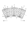
- FIG. 3 is a view showing the bending stent 100.
- the connecting portion 2 is composed of a horizontal folded intersection portion 31 that can expand and contract in the axial direction, and a vertical folded intersection portion 32 that can expand and contract in the circumferential direction. Since the number of the horizontal folded intersections 31 that can be expanded and contracted in the axial direction is larger than the number of the vertically folded intersections 32 in the connecting portion 2, the adjacent tubular portions 1 can be preferably relatively moved in the axial direction.
- the deformation of the connecting portion 2 due to the relative movement of the adjacent tubular portions 1 is referred to as “slip deformation”.
- the wire W which is a superelastic alloy, does not “resiliently deform”, and the transversely folded intersections are arranged in the circumferential direction. 31 bends by "slip deformation” in the axial direction. As a result, the bent shape can be maintained without trying to return to the original shape of the stent 100. That is, the stent 100 has a function of maintaining a shape conforming to the shape of the bent lumen (a conduit shape maintaining function).
- the vertically folded intersection portion 32 of the connecting portion 2 is expandable and contractible in the circumferential direction and is not expandable in the axial direction, the function of maintaining the conduit shape of the connecting portion 2 when the stent 100 is bent is improved. It does not contribute to. As shown in FIG. 3, the vertical folded intersection portion 32 of the connecting portion 2 does not expand and contract in the axial direction, and a reaction force returning to the original shape of the stent 100 is generated. Therefore, it is considered that forming the vertically folded intersection portion 32 in the connecting portion 2 is disadvantageous from the viewpoint of the duct shape maintaining function. However, by forming one or more longitudinally folded intersections 32 in the connecting portion 2, the stent 100 can be braided without cutting the wire W.
- FIG. 4 shows the stent 100 when it is released from the delivery system.
- the spread angle ⁇ of the stent 100 can be reduced, so that the stent 100 can be easily stored (recaptured) in the delivery system. That is, the stent 100 has a recapture function that can be easily re-stored (recaptured) in the delivery system.
- Patent Literature 1 has a large number of “meshing portions” crossing in a hook shape, and the expansion angle of the expansion mechanism when the expansion mechanism is released becomes extremely large. For this reason, it is necessary to apply a large force when re-storing (recapturing) the expansion mechanism in the delivery system, and it is difficult to re-storing (recapturing).
- the stent 100 of the present embodiment has the connecting portions 2 crossing in a hook shape.
- the connecting portion 2 including a large number of the laterally folded intersection portions 31 that undergoes slip deformation in the axial direction has a radial direction at the time of release as compared with the tubular portion 1 mainly including a linear intersection portion 33 that spreads evenly in the longitudinal axis direction. Easy to spread.
- the slip-deformable connection portion 2 and the non-slip-deformable tubular portion 1 are arranged in the axial direction. Therefore, when the stent 100 is released, the spread angle ⁇ of the stent 100 can be reduced as compared with the expansion mechanism described in Patent Document 1.
- the stent 100 of the present embodiment it is possible to achieve both the function of maintaining the shape of the conduit and the function of recapturing that can be stored again in the delivery system.
- the stent 100 of the present embodiment has a stretchable horizontal folded intersection 31 and a stretchable vertical folded intersection 32, and by appropriately arranging these two types of stretchable intersections, The stent 100 can be formed without cutting the wire W, and the degree of design freedom is high.
- the stent 100 of the present embodiment since the degree of freedom in design is high, the stent 100 having a duct shape maintaining function and a recapture function can be formed. By forming one or more vertically folded intersections 32 in the connecting portion 2, the function of maintaining the conduit shape of the connecting portion 2 is reduced, but the stent 100 can be braided without cutting the wire W. The effect can be obtained.
- the durability of the stent 100 is improved as compared with a stent having a small number of wire joints and a large number of wire joints.
- the first embodiment of the present invention has been described in detail with reference to the drawings.
- the specific configuration is not limited to this embodiment, and includes a design change and the like without departing from the gist of the present invention.
- the components shown in the above-described first embodiment and the following modified examples can be appropriately combined and configured.
- the stent 100 has the conduit shape maintaining function and the recapturing function by arranging the slip deformable connecting portion 2 and the non-slip deformable straight crossing portion 33 in the axial direction.
- I was balancing.
- the form of the stent is not limited to this.
- the number of the linear intersections 33 woven in the axial direction of the tubular portion may be increased.
- the higher the ratio of the linear intersections 33 in the stent the more the conduit shape maintaining function is suppressed. Therefore, the ratio of the linear intersections 33 in the stent is taken into consideration in consideration of the balance between the recapture function and the conduit shape maintaining function. It is desirable to determine
- the vertically folded intersection portion 32 is formed such that the first vertically folded portion 32a and the second vertically folded portion 32b intersect in a "hook shape" in the radial direction.
- the aspect of the vertically folded intersection is not limited to this.
- 5 to 8 are views showing modified examples of the vertically folded intersection. In the vertical folded intersections of these modified examples, slip deformation in the circumferential direction is suppressed. Therefore, it can be used as an alternative to the vertical folded intersection 32 in the above embodiment when it is desired to suppress a change in the circumferential slip, such as when it is necessary to indwell a stent in a lumen having a strong stenosis.
- the first vertical folded portion 32a 'and the second vertical folded portion 32b intersect.
- the first vertical folded portion 32a ' is a convex in which the wire W extending inclining in the axial direction wraps around and turns and bends to form a torsion (first torsion) L1 and convex toward the first circumferential direction R1.
- first torsion first torsion
- the first vertical folded portion 32a ′ and the second vertical folded portion 32b ′ intersect.
- the second vertical folded portion 32b ' is formed by projecting the wire W extending inclining in the axial direction to turn and bend to form a torsion (second torsion) L2 and to be convex in the second circumferential direction R2. Department.
- the vertical folded intersection 32E of the modified example shown in FIG. 8 has another wire W1 spirally arranged with respect to the first vertical folded portion 32a and the second vertical folded portion 32b that cross in a “hook shape” in the radial direction. It is wound. Therefore, the vertical folded intersection portion 32E cannot undergo slip deformation in the circumferential direction, and has a repulsive force against expansion and contraction in the circumferential direction.
- the stent 100B according to the second embodiment is different from the stent 100 according to the first embodiment in that the stent 100B is not divided into a tubular portion and a connecting portion.
- the stent 100B is formed by braiding the wire W, and has a cylindrical shape.
- the wire W forms an intersection 3 where different portions of the wire W intersect each other.
- the intersection 3 has a horizontally folded intersection 31 and a vertically folded intersection 32.
- FIG. 9 is a development view in which the stent 100B is developed in the circumferential direction.
- the wire W forming the stent 100 ⁇ / b> B extends from the start position S in a direction inclined in both the circumferential direction and the axial direction (hereinafter, referred to as an “oblique direction”). And a vertically folded intersection 32.
- the wire W extends obliquely from the start position S, repeatedly bends, and constitutes one of the intersecting wires W at the six consecutive horizontal folded intersections 31. Thereafter, the wire W forms one of the intersecting wires W at the vertically folded intersection 32 (the portion 1 shown in FIG. 9).
- the wire W folded in the circumferential direction at the vertically folded intersection portion 32 extends in an oblique direction, repeatedly bends, and forms one of the intersecting wires W in the continuous horizontally folded intersection portion 31. Thereafter, the wire W constitutes one of the intersecting wires W at the vertically folded intersection 32 (portion 2 shown in FIG. 9).
- the wire W folded in the circumferential direction at the vertically folded intersection 32 extends in an oblique direction, repeats bending, and forms one of the intersecting wires W in the continuous eight horizontally folded intersections 31. Thereafter, the wire W constitutes one of the intersecting wires W at the vertically folded intersection 32 (portion 3 shown in FIG. 9).
- the vertical folded intersection 32 of the portion 1 shown in FIG. 9 and the vertical folded intersection 32 of the portion 3 shown in FIG. 9 are arranged in an oblique direction.
- the wire W forms other horizontal folded intersections 31 and vertical folded intersections 32 by the same method, and is woven to the end point E without being cut.
- the stent 100B of this embodiment has a stretchable horizontal folded intersection 31 and a stretchable vertical folded intersection 32, and by appropriately arranging these two types of stretchable intersections, The stent 100B can be formed without cutting the wire W, and the design flexibility is high.
- the second embodiment of the present invention has been described in detail with reference to the drawings.
- the specific configuration is not limited to this embodiment, and includes a design change and the like without departing from the gist of the present invention.
- the components shown in the embodiments and the modifications can be appropriately combined and configured.
- the stent 100 ⁇ / b> B is formed by the horizontal folded intersections 31 and the vertical folded intersections 32 and does not have the linear intersections 33, but the form of the stent is limited to this. Not done.
- the stent may have a straight crossing portion 33 in a part of the stent, like a stent 100C which is a modified example of the stent 100B.
- the linear intersections 33 having repulsive force may be appropriately arranged at locations where repulsive force is required.
- the present invention can be applied to a medical device for expanding a tubular part of a human body from the inside of a lumen.
Landscapes
- Health & Medical Sciences (AREA)
- Engineering & Computer Science (AREA)
- Biomedical Technology (AREA)
- Cardiology (AREA)
- Oral & Maxillofacial Surgery (AREA)
- Transplantation (AREA)
- Heart & Thoracic Surgery (AREA)
- Vascular Medicine (AREA)
- Life Sciences & Earth Sciences (AREA)
- Animal Behavior & Ethology (AREA)
- General Health & Medical Sciences (AREA)
- Public Health (AREA)
- Veterinary Medicine (AREA)
- Media Introduction/Drainage Providing Device (AREA)
Abstract
ステントは、ワイヤを交差させて編み込まれた円管状のステントであって、前記ワイヤが互いに軸方向に折り返して交差する横折り返し交差部と、前記ワイヤが互いに周方向に折り返して交差する縦折り返し交差部と、を備える。前記縦折り返し交差部は、前記周方向の一方である第一周方向の側に屈曲して凸となる第一縦折り返し部と、前記周方向の他方である第二周方向の側に屈曲して凸となる第二縦折り返し部とが径方向に交差して形成される。
Description
近年、生体内の管状器官の管腔において狭窄や閉塞が発生した患部に、線材(素線)等からなるステントを留置することで、管状器官の管腔を拡張・保持するステント留置術が用いられている。
自己拡張性を有するステント(自己拡張型ステント)は、縮径された状態で狭窄や閉塞が発生した患部にデリバリシステムによって搬送される。デリバリシステムからリリースされたステントは、自己拡張性により拡径することで狭窄や閉塞を押し広げる。
このようなステントを留置する管腔は屈曲している場合が多いため、ステントには屈曲した管腔の形状に合わせた形状を維持する機能(管路形状維持機能)が必要とされている。管路形状維持機能を有するステントは、屈曲する管腔に留置された場合において、反力によってステント本来の形状に戻ることなく、屈曲した管腔の形状に合わせた形状を維持することができる。
特許文献1に記載の形状記憶合金を用いた拡張機構は、身体の狭窄部位を拡張させることができる。また、特許文献1に記載の拡張機構は、軸方向に伸縮可能な「かみ合わせ部」を有しており、狭窄部の管腔形状にかかわらず、管腔の形状に合わせた形状を維持することができる。
しがしながら、特許文献1に記載の拡張機構における、伸縮可能な「かみ合わせ部」はワイヤが相異なる位置から、長さ方向に折り返して互いに折り返し、筋違いに掛けられて形成されていた。ワイヤを経路に対して重複なく編み込む場合、伸縮可能な「かみ合わせ部」を所定の位置に配置することは難しく、設計自由度が低かった。
上記事情を踏まえ、本発明は、ワイヤを交差させて編み込まれたステントにおいて、伸縮可能な部分の配置に関する設計自由度が高いステントを提供することを目的とする。
上記課題を解決するために、この発明は以下の手段を提案している。
本発明の第一の態様に係るステントは、ワイヤを交差させて編み込まれた円管状のステントであって、前記ワイヤが互いに軸方向に折り返して交差する横折り返し交差部と、前記ワイヤが互いに周方向に折り返して交差する縦折り返し交差部と、を備える。
本発明の第一の態様に係るステントは、ワイヤを交差させて編み込まれた円管状のステントであって、前記ワイヤが互いに軸方向に折り返して交差する横折り返し交差部と、前記ワイヤが互いに周方向に折り返して交差する縦折り返し交差部と、を備える。
本発明のステントは、ワイヤを交差させて編み込まれたステントにおいて、伸縮可能な部分の配置に関する設計自由度が高い。
(第一実施形態)
本発明の第一実施形態について、図1から図4を参照して説明する。
図1は、本実施形態に係るステント100の全体構成を示す図である。図1は、自己拡張した状態のステント100の全体構成を示している。
本発明の第一実施形態について、図1から図4を参照して説明する。
図1は、本実施形態に係るステント100の全体構成を示す図である。図1は、自己拡張した状態のステント100の全体構成を示している。
ステント100は、ワイヤWを編み込んで形成されており、円筒形状を有する。ステント100は、自己拡張性を有しており、胆管、食道、十二指腸、小腸、大腸等の消化器系体内管腔等に留置され、主として管腔を拡張・保持する目的で使用される。本実施形態のステント100は、その外周面側を樹脂フィルム等で被覆したいわゆるカバードステントではなく、フィルム等で被覆されないアンカバードステントである。ただし、ステント100は、樹脂フィルム等で被覆してカバードステントとして用いることもできる。
ステント100は、図1に示すように、管状部1と、連結部2と、を備える。管状部1と連結部2とは、長手軸方向(以降、「軸方向」という)に交互に配列している。以降の説明において、ステント100の軸方向の一方を「第一軸方向D1」といい、ステント100の長手軸方向の他方を「第二軸方向D2」という。また、ステント100の周方向の一方を「第一周方向R1」といい、ステント100の周方向の他方を「第二周方向R2」という。
ワイヤWは、ワイヤWの異なる箇所が互いに交差する交差部3を構成する。交差部3は、横折り返し交差部31と、縦折り返し交差部32と、ワイヤの異なる箇所が直線交差する直線交差部33と、を有する。
管状部1は、ワイヤWを編み込んで、網目を周面に有する円管状に形成されている。管状部1は、縦折り返し交差部32と、直線交差部33と、を有する。
連結部2は、横折り返し交差部31と、縦折り返し交差部32と、を有する。横折り返し交差部31と縦折り返し交差部32とは周方向に配列する。本実施形態において、一個の連結部2は、七個の横折り返し交差部31と、一個の縦折り返し交差部32と、を有している。
横折り返し交差部31は、ワイヤWの異なる箇所(以降、「第一横折り返し部31a」と「第二横折り返し部31b」という)が、互いに軸方向に折り返して交差して形成されており、軸方向に伸縮可能である。
第一横折り返し部31aは、周方向に傾いて延びるワイヤWが軸方向に折り返して屈曲し、第一軸方向D1側に凸となる凸部である。
第二横折り返し部31bは、周方向に傾いて延びるワイヤWが軸方向に折り返して屈曲し、第二軸方向D2側に凸となる凸部である。
第一横折り返し部31aと第二横折り返し部31bとは、径方向に「フック状」に交差し、分離不能ではあるが相対移動可能に連結される。
縦折り返し交差部32は、ワイヤWの異なる箇所(以降、「第一縦折り返し部32a」と「第二縦折り返し部32b」という)が、互いに周方向に折り返して交差して形成されており、周方向に伸縮可能である。
第一縦折り返し部32aは、軸方向に傾いて延びるワイヤWが周方向に折り返して屈曲し、第一周方向R1側に凸となる凸部である。
第二縦折り返し部32bは、軸方向に傾いて延びるワイヤWが周方向に折り返して屈曲し、第二周方向R2側に凸となる凸部である。
第一縦折り返し部32aと第二縦折り返し部32bとは、径方向に「フック状」に交差し、分離不能ではあるが相対移動可能に連結される。
直線交差部33は、周方向にも軸方向にも傾いて延びるワイヤWが互いに折り返さず交差して形成される。ワイヤWに沿って連続する直線交差部33において、ワイヤWは、交差するワイヤWの径方向外側と径方向内側とを交互に通過する。このように編み込まれた直線交差部33は、軸方向および周方向の伸縮に対する反発力を有する。
図2は、ステント100を周方向に展開した展開図である。
ステント100を形成するワイヤWは、図2に示すように、スタート位置Sから周方向にも軸方向にも傾いた方向(以降、「斜め方向」という)に延び、直線交差部33と、横折り返し交差部31と、縦折り返し交差部32と、を形成する。
ステント100を形成するワイヤWは、図2に示すように、スタート位置Sから周方向にも軸方向にも傾いた方向(以降、「斜め方向」という)に延び、直線交差部33と、横折り返し交差部31と、縦折り返し交差部32と、を形成する。
ワイヤWは、スタート位置Sから斜め方向に延び、5つの連続する直線交差部33において、交差するワイヤWの一方を構成する。その後、ワイヤWは連結部2の横折り返し交差部31において、交差するワイヤWの一方を構成する(図2に示す1の部分)。
連結部2で軸方向に折り返したワイヤWは斜め方向に延び、5つの連続する直線交差部33において、交差するワイヤWの一方を構成する。その後、ワイヤWは連結部2の横折り返し交差部31において、交差するワイヤWの一方を構成する(図2に示す2の部分)。
連結部2で軸方向に折り返したワイヤWは斜め方向に延び、5つの連続する直線交差部33において、交差するワイヤWの一方を構成する。その後、ワイヤWは連結部2の横折り返し交差部31において、交差するワイヤWの一方を構成する(図2に示す3の部分)。
連結部2で軸方向に折り返したワイヤWは斜め方向に延び、2つの連続する直線交差部33において、交差するワイヤWの一方を構成する。その後、ワイヤWは縦折り返し交差部32において、交差するワイヤWの一方を構成する(図2に示す4の部分)。
縦折り返し交差部32で周方向に折り返したワイヤWは斜め方向に延び、2つの連続する直線交差部33において、交差するワイヤWの一方を構成する。その後、ワイヤWは連結部2の横折り返し交差部31において、交差するワイヤWの一方を構成する(図2に示す5の部分)。
連結部2で軸方向に折り返したワイヤWは斜め方向に延び、5つの連続する直線交差部33において、交差するワイヤWの一方を構成する。その後、ワイヤWは連結部2の縦折り返し交差部32において、交差するワイヤWの一方を構成する(図2に示す6の部分)。
ワイヤWは、連結部2において縦折り返し交差部32における交差するワイヤWの一方を構成することで、連結部2を挟んで隣り合う管状部1を、切断されずに連続して編み込むことができる。
連結部2の縦折り返し交差部32で周方向に折り返したワイヤWは斜め方向に延び、5つの連続する直線交差部33において、交差するワイヤWの一方を構成する。その後、ワイヤWは連結部2の横折り返し交差部31において、交差するワイヤWの一方を構成する(図2に示す7の部分)。
連結部2で軸方向に折り返したワイヤWは斜め方向に延び、5つの連続する直線交差部33において、交差するワイヤWの一方を構成する。その後、ワイヤWは連結部2の横折り返し交差部31において、交差するワイヤWの一方を構成する(図2に示す8の部分)。
ワイヤWは、同様の方法により、他の横折り返し交差部31、縦折り返し交差部32および直線交差部33を形成し、切断されることなく、終了地点Eまで編み込まれる。
スタート位置Sおよび終了地点Eに位置するワイヤWの両端部は、カシメ、レーザ溶接、ロウ付け等の接合法を用いて連結される。図3では、ワイヤWは、横折り返し交差部31における端部を接合しているが、端部では応力の集中が起こりやすいことを考慮するならば、横折り返し交差部31の端部ではなく、直線部分にて接合する方が望ましい。
ワイヤWは、NiTiを主材料とする超弾性合金である。NiTiを主材料とする超弾性合金は、編み込んだ時点では永久変形をしておらず、編み込んだ状態で熱処理を加えることで編み込み形状が記憶される。
次に、ステント100の動作について説明する。
ステント100は、縮径された状態でデリバリシステムに格納され、狭窄や閉塞が発生した患部に搬送される。デリバリシステムからリリースされたステント100は、自己拡張性により拡径することで狭窄や閉塞を押し広げる。ステント100は、構成が単純であるため、デリバリシステムに収納された際の収納径を小さくすることができる。
ステント100は、縮径された状態でデリバリシステムに格納され、狭窄や閉塞が発生した患部に搬送される。デリバリシステムからリリースされたステント100は、自己拡張性により拡径することで狭窄や閉塞を押し広げる。ステント100は、構成が単純であるため、デリバリシステムに収納された際の収納径を小さくすることができる。
図3は、屈曲するステント100を示す図である。連結部2は、軸方向に伸縮可能な横折り返し交差部31と、周方向に伸縮可能な縦折り返し交差部32と、で構成されている。連結部2は、縦折り返し交差部32の数より、軸方向に伸縮可能な横折り返し交差部31の数が多いため、隣り合う管状部1を軸方向に好適に相対移動させることができる。以降、隣り合う管状部1の相対移動による連結部2の変形を「すべり変形」という。
ステント100は、図3に示すように、ステント100全体を長手軸に対して屈曲させた場合、超弾性合金であるワイヤWが「弾性変形」することなく、周方向に配列する横折り返し交差部31が軸方向に「すべり変形」して屈曲する。その結果、ステント100本来の形状に戻ろうとせず、屈曲形状を維持することが可能である。すなわち、ステント100は、屈曲した管腔の形状に合わせた形状を維持する機能(管路形状維持機能)を有する。
ここで、連結部2の縦折り返し交差部32は、周方向に伸縮可能であり、軸方向に伸縮可能ではないため、ステント100を屈曲させた場合における連結部2の管路形状維持機能の向上に寄与するものではない。図3に示すように、連結部2の縦折り返し交差部32は、軸方向に伸縮しておらず、ステント100本来の形状に戻る反力が発生する。そのため、連結部2に縦折り返し交差部32を形成することは、管路形状維持機能の観点では不利であるとも考えられる。しかしながら、連結部2に一以上の縦折り返し交差部32を形成することで、ワイヤWが切断されることなく、ステント100を編み込むことができる。
図4は、デリバリシステムからリリースする際のステント100を示す図である。
デリバリシステムの先端のアウターシースAからステント100がリリースされる際、ステント100の広がり角度θを小さくすることができるため、ステント100をデリバリシステムに容易に再収納(リキャプチャ)することができる。すなわち、ステント100は、デリバリシステムに容易に再収納(リキャプチャ)することができるリキャプチャ機能を有する。
デリバリシステムの先端のアウターシースAからステント100がリリースされる際、ステント100の広がり角度θを小さくすることができるため、ステント100をデリバリシステムに容易に再収納(リキャプチャ)することができる。すなわち、ステント100は、デリバリシステムに容易に再収納(リキャプチャ)することができるリキャプチャ機能を有する。
特許文献1に記載の拡張機構は、フック状に交差した「かみ合わせ部」の数が多く、拡張機構がリリースされた際の拡張機構の広がり角度が非常に大きくなる。そのため、デリバリシステムに拡張機構を再収納(リキャプチャ)する際に大きな力を加える必要があり、再収納(リキャプチャ)することが難しい。
本実施形態のステント100は、フック状に交差した連結部2を有している。軸方向へのすべり変形を行う横折り返し交差部31を多く含む連結部2は、長手軸方向に均等に広がる直線交差部33を主として構成された管状部1と比較して、リリース時において径方向に広がりやすい。しかしながら、ステント100は、すべり変形可能な連結部2と、すべり変形不能な管状部1とが、軸方向に配置される。そのため、ステント100がリリースされる際、特許文献1に記載の拡張機構と比較して、ステント100の広がり角度θを小さくすることができる。
本実施形態のステント100によれば、管路形状維持機能と、デリバリシステムに再収納することができるリキャプチャ機能と、を両立することができる。
本実施形態のステント100によれば、伸縮可能な横折り返し交差部31と伸縮可能な縦折り返し交差部32とを有しており、これら二種類の伸縮可能な交差部を適宜配置することで、ワイヤWが切断されることなくステント100を形成することができ、設計自由度が高い。
本実施形態のステント100によれば、設計自由度が高いため、管路形状維持機能およびリキャプチャ機能を有するステント100を形成することができる。連結部2に一以上の縦折り返し交差部32を形成することで、連結部2の管路形状維持機能は低下するが、ワイヤWが切断されることなく、ステント100を編み込むことができる有利な効果を得ることができる。ワイヤの接合部分が少なく、ワイヤの接合部分が多いステントと比較して、ステント100の耐久性が向上する。
以上、本発明の第一実施形態について図面を参照して詳述したが、具体的な構成はこの実施形態に限られるものではなく、本発明の要旨を逸脱しない範囲の設計変更等も含まれる。また、上述の第一実施形態および以下で示す変形例において示した構成要素は適宜に組み合わせて構成することが可能である。
(変形例1)
例えば、上記実施形態において、ステント100は、すべり変形可能な連結部2と、すべり変形不能な直線交差部33とを、軸方向に配置することで、管路形状維持機能とリキャプチャ機能とを両立させていた。しかしながらステントの態様はこれに限定されない。さらにリキャプチャ機能を高める場合、管状部の軸方向に編み込まれる直線交差部33の数を増やしてもよい。ただし、ステントにおける直線交差部33の比率を高くするほど、管路形状維持機能が抑制されるため、リキャプチャ機能と管路形状維持機能とのバランスを考慮してステントにおける直線交差部33の比率を決定することが望ましい。
例えば、上記実施形態において、ステント100は、すべり変形可能な連結部2と、すべり変形不能な直線交差部33とを、軸方向に配置することで、管路形状維持機能とリキャプチャ機能とを両立させていた。しかしながらステントの態様はこれに限定されない。さらにリキャプチャ機能を高める場合、管状部の軸方向に編み込まれる直線交差部33の数を増やしてもよい。ただし、ステントにおける直線交差部33の比率を高くするほど、管路形状維持機能が抑制されるため、リキャプチャ機能と管路形状維持機能とのバランスを考慮してステントにおける直線交差部33の比率を決定することが望ましい。
(変形例2)
例えば、上記実施形態において、縦折り返し交差部32は、第一縦折り返し部32aと第二縦折り返し部32bとは、径方向に「フック状」に交差して形成されていた。しかしながら縦折り返し交差部の態様はこれに限定されない。図5から図8は縦折り返し交差部の変形例を示す図である。これらの変形例の縦折り返し交差部は、周方向へのすべり変形が抑制される。そのため、狭窄力が強い管腔にステントを留置する必要がある場合等の周方向のすべり変更を抑制したい場合に、上記実施形態の縦折り返し交差部32の代替として用いることができる。
例えば、上記実施形態において、縦折り返し交差部32は、第一縦折り返し部32aと第二縦折り返し部32bとは、径方向に「フック状」に交差して形成されていた。しかしながら縦折り返し交差部の態様はこれに限定されない。図5から図8は縦折り返し交差部の変形例を示す図である。これらの変形例の縦折り返し交差部は、周方向へのすべり変形が抑制される。そのため、狭窄力が強い管腔にステントを留置する必要がある場合等の周方向のすべり変更を抑制したい場合に、上記実施形態の縦折り返し交差部32の代替として用いることができる。
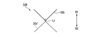
図5に示す変形例の縦折り返し交差部32Bは、第一縦折り返し部32a´と、第二縦折り返し部32bと、が交差している。第一縦折り返し部32a´は、軸方向に傾いて延びるワイヤWが周回して折り返して屈曲し、ねじり目(第一ねじり目)L1を形成し、第一周方向R1側に凸となる凸部である。第二縦折り返し部32bは、第一縦折り返し部32a´の第一ねじり目L1を通過しているため、縦折り返し交差部32Bは周方向のすべり変形が抑制される。
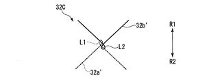
図6に示す変形例の縦折り返し交差部32Cは、第一縦折り返し部32a´と、第二縦折り返し部32b´と、が交差している。第二縦折り返し部32b´は、軸方向に傾いて延びるワイヤWが周回して折り返して屈曲し、ねじり目(第二ねじり目)L2を形成し、第二周方向R2側に凸となる凸部である。第一縦折り返し部32a´は第二縦折り返し部32b´の第二ねじり目L2を通過し、第二縦折り返し部32b´は第一縦折り返し部32a´の第一ねじり目L1を通過しているため、縦折り返し交差部32Cは周方向のすべり変形が抑制される。
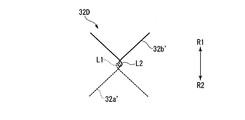
図7に示す変形例の縦折り返し交差部32Dは、第一縦折り返し部32a´と、第二縦折り返し部32b´と、が交差している。第一縦折り返し部32a´の第一ねじり目L1と、第二縦折り返し部32b´の第二ねじり目L2と、が交差している。そのため、縦折り返し交差部32Dは周方向のすべり変形は不能となり、逆に周方向の伸縮に対する反発力を有する。
図8に示す変形例の縦折り返し交差部32Eは、径方向に「フック状」に交差する第一縦折り返し部32aと第二縦折り返し部32bとに対して、別のワイヤW1がらせん状に巻き付けられている。そのため、縦折り返し交差部32Eは周方向のすべり変形は不能となり、逆に周方向の伸縮に対する反発力を有する。
(第二実施形態)
本発明の第二実施形態について、図9を参照して説明する。以降の説明において、既に説明したものと共通する構成については、同一の符号を付して重複する説明を省略する。第二実施形態に係るステント100Bは、第一実施形態に係るステント100と比較して、管状部と連結部とに区分されていない点が異なる。
本発明の第二実施形態について、図9を参照して説明する。以降の説明において、既に説明したものと共通する構成については、同一の符号を付して重複する説明を省略する。第二実施形態に係るステント100Bは、第一実施形態に係るステント100と比較して、管状部と連結部とに区分されていない点が異なる。
ステント100Bは、ワイヤWを編み込んで形成されており、円筒形状を有する。
ワイヤWは、ワイヤWの異なる箇所が互いに交差する交差部3を構成する。交差部3は、横折り返し交差部31と、縦折り返し交差部32と、を有する。
ワイヤWは、ワイヤWの異なる箇所が互いに交差する交差部3を構成する。交差部3は、横折り返し交差部31と、縦折り返し交差部32と、を有する。
図9は、ステント100Bを周方向に展開した展開図である。
ステント100Bを形成するワイヤWは、図9に示すように、スタート位置Sから周方向にも軸方向にも傾いた方向(以降、「斜め方向」という)に延び、横折り返し交差部31と、縦折り返し交差部32と、を形成する。
ステント100Bを形成するワイヤWは、図9に示すように、スタート位置Sから周方向にも軸方向にも傾いた方向(以降、「斜め方向」という)に延び、横折り返し交差部31と、縦折り返し交差部32と、を形成する。
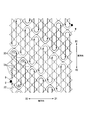
ワイヤWは、スタート位置Sから斜め方向に延び、屈曲を繰り返し、連続する6個の横折り返し交差部31において、交差するワイヤWの一方を構成する。その後、ワイヤWは縦折り返し交差部32において、交差するワイヤWの一方を構成する(図9に示す1の部分)。
縦折り返し交差部32で周方向に折り返したワイヤWは斜め方向に延び、屈曲を繰り返し、連続する横折り返し交差部31において、交差するワイヤWの一方を構成する。その後、ワイヤWは縦折り返し交差部32において、交差するワイヤWの一方を構成する(図9に示す2の部分)。
縦折り返し交差部32で周方向に折り返したワイヤWは斜め方向に延び、屈曲を繰り返し、連続する8個の横折り返し交差部31において、交差するワイヤWの一方を構成する。その後、ワイヤWは縦折り返し交差部32において、交差するワイヤWの一方を構成する(図9に示す3の部分)。
図9に示す1の部分の縦折り返し交差部32と、図9に示す3の部分の縦折り返し交差部32と、は斜め方向に配列する。
ワイヤWは、同様の方法により、他の横折り返し交差部31および縦折り返し交差部32を形成し、切断されることなく、終了地点Eまで編み込まれる。
本実施形態のステント100Bによれば、伸縮可能な横折り返し交差部31と伸縮可能な縦折り返し交差部32とを有しており、これら二種類の伸縮可能な交差部を適宜配置することで、ワイヤWが切断されることなくステント100Bを形成することができ、設計自由度が高い。
以上、本発明の第二実施形態について図面を参照して詳述したが、具体的な構成はこの実施形態に限られるものではなく、本発明の要旨を逸脱しない範囲の設計変更等も含まれる。また、実施形態および変形例において示した構成要素は適宜に組み合わせて構成することが可能である。
(変形例3)
例えば、上記実施形態において、ステント100Bは、横折り返し交差部31と、縦折り返し交差部32と、によって形成されており、直線交差部33を有していなかったが、ステントの態様はこれに限定されない。ステントは、図10に示すようステント100Bの変形例であるステント100Cのように、ステント一部に直線交差部33を有してもよい。横折り返し交差部31と縦折り返し交差部32により設計自由度を確保したうえで、反発力を有する直線交差部33を、反発力が必要な箇所に適宜配置してもよい。
例えば、上記実施形態において、ステント100Bは、横折り返し交差部31と、縦折り返し交差部32と、によって形成されており、直線交差部33を有していなかったが、ステントの態様はこれに限定されない。ステントは、図10に示すようステント100Bの変形例であるステント100Cのように、ステント一部に直線交差部33を有してもよい。横折り返し交差部31と縦折り返し交差部32により設計自由度を確保したうえで、反発力を有する直線交差部33を、反発力が必要な箇所に適宜配置してもよい。
本発明は、人体の管状の部分を管腔内部から広げる医療機器に適用することができる。
100,100B,100C ステント
1 管状部
2 連結部
3 交差部
31 横折り返し交差部
31a 第一横折り返し部
31b 第二横折り返し部
32,32B,32C,32D,32E 縦折り返し交差部
32a 第一縦折り返し部
32b 第二縦折り返し部
33 直線交差部
L1 第一ねじり目
L2 第二ねじり目
1 管状部
2 連結部
3 交差部
31 横折り返し交差部
31a 第一横折り返し部
31b 第二横折り返し部
32,32B,32C,32D,32E 縦折り返し交差部
32a 第一縦折り返し部
32b 第二縦折り返し部
33 直線交差部
L1 第一ねじり目
L2 第二ねじり目
Claims (11)
- ワイヤを交差させて編み込まれた円管状のステントであって、
前記ワイヤが互いに軸方向に折り返して交差する横折り返し交差部と、
前記ワイヤが互いに周方向に折り返して交差する縦折り返し交差部と、
を備える、
ステント。 - 前記縦折り返し交差部は、
前記周方向の一方である第一周方向の側に屈曲して凸となる第一縦折り返し部と、
前記周方向の他方である第二周方向の側に屈曲して凸となる第二縦折り返し部とが
径方向に交差して形成される、
請求項1に記載のステント。 - 前記横折り返し交差部は、
前記軸方向の一方である第一軸方向の側に屈曲して凸となる第一横折り返し部と、
前記軸方向の他方である第二軸方向の側に屈曲して凸となる第二横折り返し部とが
径方向に交差して形成される、
請求項1または請求項2に記載のステント。 - 前記ワイヤが直線交差する直線交差部をさらに備える、
請求項1から請求項3のいずれか一項に記載のステント。 - 前記第一縦折り返し部は、周回して第一ねじり目を形成し、
前記第一ねじり目が前記第二縦折り返し部と交差している、
請求項2から請求項4のいずれか一項に記載のステント。 - 前記第二縦折り返し部は、周回して第二ねじり目を形成し、
前記第二ねじり目が前記第一縦折り返し部と交差している、
請求項2から請求項5のいずれか一項に記載のステント。 - 前記第一ねじり目と前記第二ねじり目とが交差する、
請求項6に記載のステント。 - 前記縦折り返し交差部は、第一縦折り返し部と第二縦折り返し部とにらせん状に巻き付くワイヤをさらに有する、
請求項2から請求項4のいずれか一項に記載のステント。 - 複数の前記横折り返し交差部と一以上の前記縦折り返し交差部とが前記周方向に配列した連結部が、前記軸方向に間隔をあけて配列する、
請求項4に記載のステント。 - 前記直線交差部と前記縦折り返し交差部を有する管状部と、
前記連結部とが、
前記軸方向に交互に配列する、
請求項9に記載のステント。 - 前記ワイヤは超弾性合金で形成されており、
前記ステントは生体の管腔を拡張する自己拡張性を有する
請求項1から請求項10のいずれか一項に記載のステント。
Priority Applications (4)
| Application Number | Priority Date | Filing Date | Title |
|---|---|---|---|
| JP2020546630A JP7085010B2 (ja) | 2018-09-13 | 2018-09-13 | ステント |
| PCT/JP2018/034005 WO2020054027A1 (ja) | 2018-09-13 | 2018-09-13 | ステント |
| CN201880097392.4A CN112672718B (zh) | 2018-09-13 | 2018-09-13 | 支架 |
| US17/198,411 US11559414B2 (en) | 2018-09-13 | 2021-03-11 | Stent |
Applications Claiming Priority (1)
| Application Number | Priority Date | Filing Date | Title |
|---|---|---|---|
| PCT/JP2018/034005 WO2020054027A1 (ja) | 2018-09-13 | 2018-09-13 | ステント |
Related Child Applications (1)
| Application Number | Title | Priority Date | Filing Date |
|---|---|---|---|
| US17/198,411 Continuation US11559414B2 (en) | 2018-09-13 | 2021-03-11 | Stent |
Publications (1)
| Publication Number | Publication Date |
|---|---|
| WO2020054027A1 true WO2020054027A1 (ja) | 2020-03-19 |
Family
ID=69778500
Family Applications (1)
| Application Number | Title | Priority Date | Filing Date |
|---|---|---|---|
| PCT/JP2018/034005 Ceased WO2020054027A1 (ja) | 2018-09-13 | 2018-09-13 | ステント |
Country Status (4)
| Country | Link |
|---|---|
| US (1) | US11559414B2 (ja) |
| JP (1) | JP7085010B2 (ja) |
| CN (1) | CN112672718B (ja) |
| WO (1) | WO2020054027A1 (ja) |
Cited By (4)
| Publication number | Priority date | Publication date | Assignee | Title |
|---|---|---|---|---|
| JP2023008427A (ja) * | 2021-07-06 | 2023-01-19 | 株式会社Jimro | ステント |
| US11986406B2 (en) | 2021-02-16 | 2024-05-21 | Olympus Corporation | Stent |
| WO2024154363A1 (ja) * | 2023-01-19 | 2024-07-25 | 朝日インテック株式会社 | ステント |
| US20240390970A1 (en) * | 2021-09-24 | 2024-11-28 | Microport Urocare (Jiaxing) Co., Ltd. | Stent for use in intestinal tract, and weaving method therefor |
Families Citing this family (3)
| Publication number | Priority date | Publication date | Assignee | Title |
|---|---|---|---|---|
| CN116327460A (zh) * | 2021-12-24 | 2023-06-27 | 微创优通医疗科技(嘉兴)有限公司 | 支架及支架编织方法 |
| CN116616970A (zh) * | 2022-02-22 | 2023-08-22 | 上海微创心脉医疗科技(集团)股份有限公司 | 医用支架及医用支架系统 |
| CN115553972B (zh) * | 2022-10-19 | 2023-10-20 | 常州乐奥医疗科技股份有限公司 | 一种胆道支架制造方法及胆道支架 |
Citations (5)
| Publication number | Priority date | Publication date | Assignee | Title |
|---|---|---|---|---|
| JPH10272190A (ja) * | 1997-02-04 | 1998-10-13 | Solco Co Ltd | 体腔拡張用ステント |
| JP2000060975A (ja) * | 1997-08-01 | 2000-02-29 | Schneider Usa Inc | 放射線不透過性標識及びその使用方法 |
| JP2003079743A (ja) * | 2001-09-17 | 2003-03-18 | Piolax Medical Device:Kk | ステント及びステント付きグラフト |
| JP2004528862A (ja) * | 2000-11-15 | 2004-09-24 | エンドロジックス、インク | 埋め込み可能な脈管移植片 |
| JP2014522268A (ja) * | 2011-05-23 | 2014-09-04 | ラザラス エフェクト, インコーポレイテッド | 回収システムおよびその使用方法 |
Family Cites Families (11)
| Publication number | Priority date | Publication date | Assignee | Title |
|---|---|---|---|---|
| KR100457630B1 (ko) | 2001-04-04 | 2004-11-18 | (주) 태웅메디칼 | 형상기억합금을 이용한 가변상태 유지형 확장기구의제조방법과 이에 의해 제조된 확장기구 |
| JP4094367B2 (ja) * | 2002-07-24 | 2008-06-04 | 株式会社パイオラックスメディカルデバイス | ステント及びステント付きグラフト |
| CN2571401Y (zh) * | 2002-08-20 | 2003-09-10 | 胡晓民 | 医用镍钛记忆合金无交叉支架 |
| JP4429833B2 (ja) * | 2004-07-21 | 2010-03-10 | Junken Medical株式会社 | ステント及びステントグラフト |
| GB2418362C (en) * | 2004-09-22 | 2010-05-05 | Veryan Medical Ltd | Stent |
| US20130289690A1 (en) * | 2011-11-01 | 2013-10-31 | Hira V. Thapliyal | Personalized prosthesis and methods of use |
| JP6045036B2 (ja) * | 2014-01-28 | 2016-12-14 | 日本ライフライン株式会社 | ステント |
| KR101654861B1 (ko) * | 2014-08-27 | 2016-09-06 | 주식회사 비씨엠 | 스텐트와 그 스텐트 제조방법 |
| JP6177259B2 (ja) * | 2015-01-13 | 2017-08-09 | 日本ライフライン株式会社 | ステントおよびステントグラフト |
| KR101728319B1 (ko) * | 2015-04-15 | 2017-04-19 | 주식회사 엠아이텍 | 스텐트 제조방법 |
| EP3302311B1 (en) * | 2015-06-03 | 2019-11-20 | Covidien LP | Flexible intravascular treatment devices |
-
2018
- 2018-09-13 JP JP2020546630A patent/JP7085010B2/ja active Active
- 2018-09-13 CN CN201880097392.4A patent/CN112672718B/zh active Active
- 2018-09-13 WO PCT/JP2018/034005 patent/WO2020054027A1/ja not_active Ceased
-
2021
- 2021-03-11 US US17/198,411 patent/US11559414B2/en active Active
Patent Citations (5)
| Publication number | Priority date | Publication date | Assignee | Title |
|---|---|---|---|---|
| JPH10272190A (ja) * | 1997-02-04 | 1998-10-13 | Solco Co Ltd | 体腔拡張用ステント |
| JP2000060975A (ja) * | 1997-08-01 | 2000-02-29 | Schneider Usa Inc | 放射線不透過性標識及びその使用方法 |
| JP2004528862A (ja) * | 2000-11-15 | 2004-09-24 | エンドロジックス、インク | 埋め込み可能な脈管移植片 |
| JP2003079743A (ja) * | 2001-09-17 | 2003-03-18 | Piolax Medical Device:Kk | ステント及びステント付きグラフト |
| JP2014522268A (ja) * | 2011-05-23 | 2014-09-04 | ラザラス エフェクト, インコーポレイテッド | 回収システムおよびその使用方法 |
Cited By (5)
| Publication number | Priority date | Publication date | Assignee | Title |
|---|---|---|---|---|
| US11986406B2 (en) | 2021-02-16 | 2024-05-21 | Olympus Corporation | Stent |
| JP2023008427A (ja) * | 2021-07-06 | 2023-01-19 | 株式会社Jimro | ステント |
| JP7702287B2 (ja) | 2021-07-06 | 2025-07-03 | 株式会社Jimro | ステント |
| US20240390970A1 (en) * | 2021-09-24 | 2024-11-28 | Microport Urocare (Jiaxing) Co., Ltd. | Stent for use in intestinal tract, and weaving method therefor |
| WO2024154363A1 (ja) * | 2023-01-19 | 2024-07-25 | 朝日インテック株式会社 | ステント |
Also Published As
| Publication number | Publication date |
|---|---|
| US11559414B2 (en) | 2023-01-24 |
| JPWO2020054027A1 (ja) | 2021-08-30 |
| CN112672718B (zh) | 2024-05-14 |
| US20210220155A1 (en) | 2021-07-22 |
| CN112672718A (zh) | 2021-04-16 |
| JP7085010B2 (ja) | 2022-06-15 |
Similar Documents
| Publication | Publication Date | Title |
|---|---|---|
| WO2020054027A1 (ja) | ステント | |
| JP7075493B2 (ja) | ステント | |
| JP5523700B2 (ja) | フレキシブルステント | |
| KR101314224B1 (ko) | 플렉서블 장치 | |
| JP7760807B2 (ja) | 胆管ステント | |
| US20180318115A1 (en) | Fracture resistant stent | |
| JP6177259B2 (ja) | ステントおよびステントグラフト | |
| WO2020194506A1 (ja) | ステント | |
| JP2018527124A5 (ja) | ||
| JP7333433B2 (ja) | ステント | |
| JPWO2020045315A1 (ja) | 消化管ステント | |
| JP2003334255A (ja) | ステント及びステントグラフト | |
| JP2021129982A (ja) | ステント | |
| JP7567115B2 (ja) | ステント | |
| JP7646967B2 (ja) | ステント | |
| JP7815717B2 (ja) | 編み込みステント、編み込みステント製造用治具および編み込みステントの製造方法 | |
| JP2019118810A (ja) | 内腔拡張用3重構造ステント及びその製造方法 | |
| JP5037514B2 (ja) | ねじれ解消形状を有するステント | |
| WO2022181661A1 (ja) | ステント | |
| JP2023118339A (ja) | ステント |
Legal Events
| Date | Code | Title | Description |
|---|---|---|---|
| 121 | Ep: the epo has been informed by wipo that ep was designated in this application |
Ref document number: 18933336 Country of ref document: EP Kind code of ref document: A1 |
|
| ENP | Entry into the national phase |
Ref document number: 2020546630 Country of ref document: JP Kind code of ref document: A |
|
| NENP | Non-entry into the national phase |
Ref country code: DE |
|
| 122 | Ep: pct application non-entry in european phase |
Ref document number: 18933336 Country of ref document: EP Kind code of ref document: A1 |