WO2020050125A1 - タイヤユニフォミティデータの補正方法 - Google Patents
タイヤユニフォミティデータの補正方法 Download PDFInfo
- Publication number
- WO2020050125A1 WO2020050125A1 PCT/JP2019/033907 JP2019033907W WO2020050125A1 WO 2020050125 A1 WO2020050125 A1 WO 2020050125A1 JP 2019033907 W JP2019033907 W JP 2019033907W WO 2020050125 A1 WO2020050125 A1 WO 2020050125A1
- Authority
- WO
- WIPO (PCT)
- Prior art keywords
- tire
- tire uniformity
- transfer function
- correcting
- rim
- Prior art date
- Legal status (The legal status is an assumption and is not a legal conclusion. Google has not performed a legal analysis and makes no representation as to the accuracy of the status listed.)
- Ceased
Links
Images





Classifications
-
- B—PERFORMING OPERATIONS; TRANSPORTING
- B60—VEHICLES IN GENERAL
- B60C—VEHICLE TYRES; TYRE INFLATION; TYRE CHANGING; CONNECTING VALVES TO INFLATABLE ELASTIC BODIES IN GENERAL; DEVICES OR ARRANGEMENTS RELATED TO TYRES
- B60C19/00—Tyre parts or constructions not otherwise provided for
-
- G—PHYSICS
- G01—MEASURING; TESTING
- G01M—TESTING STATIC OR DYNAMIC BALANCE OF MACHINES OR STRUCTURES; TESTING OF STRUCTURES OR APPARATUS, NOT OTHERWISE PROVIDED FOR
- G01M1/00—Testing static or dynamic balance of machines or structures
- G01M1/14—Determining imbalance
- G01M1/16—Determining imbalance by oscillating or rotating the body to be tested
-
- G—PHYSICS
- G01—MEASURING; TESTING
- G01M—TESTING STATIC OR DYNAMIC BALANCE OF MACHINES OR STRUCTURES; TESTING OF STRUCTURES OR APPARATUS, NOT OTHERWISE PROVIDED FOR
- G01M17/00—Testing of vehicles
- G01M17/007—Wheeled or endless-tracked vehicles
- G01M17/02—Tyres
Definitions
- the present invention relates to a method for correcting tire uniformity data.
- TUM tire uniformity machine
- Each of the TUM includes a tire shaft on which a tire can be mounted, a rotating drum rotating around a drive shaft parallel to the tire shaft, and each of the tires generated by rotating the rotating drum while pressing the rotating drum against the tire.
- a load cell mounted on a housing on the tire shaft side for measuring a directional fluctuating load waveform (referred to as a uniformity waveform) is known (for example, see Patent Document 1).
- the measured load measured by the load cell with respect to the uniformity waveform in each direction of the tire rotating in a state where the rotating drum is pressed i.e., the excitation force of the tire.
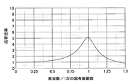
- the response transfer function ⁇ referred to as "measured load transfer function (response magnification)" ⁇ has a relationship as shown in FIG.
- the measured load transfer function (response magnification) as shown in FIG. 9, the measured load transfer function (response magnification) is 1 at low speed rotation of the tire (that is, in a low frequency band).
- An accurate (highly accurate) tire uniformity waveform can be obtained from the measured measurement load. Therefore, this signal can be subjected to predetermined signal processing (for example, extraction of the amplitude and phase of the rotational speed component and higher-order components by FFT calculation) to output accurate (highly accurate) tire uniformity data.
- An object of the present invention is to provide an accurate (highly accurate) tire uniformity data for a high-order component frequency of various types of tires rotating at high speed without using a TUM (tire uniformity machine) having excessive rigidity. It is an object of the present invention to provide a method for correcting tire uniformity data that can be obtained.
- the method of correcting tire uniformity data includes a method of measuring a tire uniformity waveform generated on a tire shaft that holds a tire that is driven and rotated in contact with a rotating drum.
- a tire uniformity machine provided with a tire uniformity measurement unit having a force sensor installed in a housing, and a signal processing operation unit that performs predetermined signal processing on a tire uniformity waveform measured by the force sensor and outputs the result as tire uniformity data.
- a tire uniformity data correction method in which a natural vibration characteristic of the tire uniformity machine in a predetermined state is measured in advance, taking into account the measurement result of the natural vibration characteristic, and measuring the tire uniformity waveform.
- the predetermined state may be a state where no mass body is attached to the tire uniformity machine.
- the predetermined state may be a state in which a mass body is attached to the tire uniformity machine.
- FIG. 3 is a schematic side view for explaining a TUM according to the method for correcting tire uniformity data of the present invention.
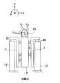
- FIG. 2 is an explanatory diagram for explaining a structure in a first state in which nothing is added to the TUM shown in FIG. 1 and a concept of an exciting force.
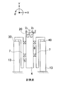
- FIG. 3 is an explanatory diagram of excitation points at which three excitation forces are applied so as to be linearly independent of a reference position in the conceptual structure illustrated in FIG. 2.
- FIG. 3 is an explanatory diagram of three measurement points for measuring acceleration in the conceptual structure shown in FIG. 2.
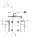
- FIG. 4 is an explanatory diagram for describing a measured load measured by a force sensor and a measured load around a reference position in the conceptual structure illustrated in FIG. 3.
- FIG. 3 is a schematic side view for explaining a TUM according to the method for correcting tire uniformity data of the present invention.
- FIG. 2 is an explanatory diagram for explaining a structure in a first state in which nothing is added to the TUM shown in
- FIG. 9 is an explanatory diagram for describing definitions of m, I, and s in first, second, third, and fourth states in deriving a mass matrix M.
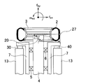
- FIG. 9 is an explanatory diagram for explaining an excitation force vector conversion matrix Tfe for converting an excitation force from a reference position to an excitation force at an arbitrary contact portion where an actual tire and a rotating drum contact.
- FIG. 4 is an explanatory diagram for describing a load transfer function matrix G and a transition load transfer function matrix G ′ at a reference position illustrated in FIG. 3.
- 4 is a flowchart illustrating a method for correcting tire uniformity data according to the present invention. It is explanatory drawing for demonstrating the measured load transfer function (response magnification) of the conventional TUM (with tire and rim).
- the inventor of the present invention has made it possible to provide the housing on the tire shaft side with respect to the frequency of higher-order components of various types of tires rotating at high speed without using a TUM (tire uniformity machine) having excessive rigidity.
- TUM tire uniformity machine
- various tires refer to tires having different masses and sizes.
- the tire uniformity waveform refers to a radial variable load waveform (tire RFV waveform), a tractive variable load waveform (tire TFV waveform) and a lateral variable load waveform (tire LFV waveform) measured by a force sensor. )
- tire uniformity data is a general term for data obtained by performing predetermined signal processing on the tire uniformity waveform ⁇ for example, extracting a rotation speed component and an amplitude and a phase of a higher-order component by FFT calculation ⁇ .
- the first invention according to the method for correcting tire uniformity data of the present invention is a method of measuring a tire uniformity waveform generated on a tire shaft that holds a tire that is driven and rotated in contact with a rotating drum.
- a tire uniformity machine provided with a tire uniformity measurement unit having a force sensor installed in a housing, and a signal processing operation unit that performs predetermined signal processing on a tire uniformity waveform measured by the force sensor and outputs the result as tire uniformity data.
- the second invention according to the method for correcting tire uniformity data of the present invention is a method for measuring a tire uniformity waveform generated on a tire shaft that holds a tire that is driven and rotated in contact with a rotating drum.
- a tire uniformity machine provided with a tire uniformity measurement unit having a force sensor installed in a housing, and a signal processing operation unit that performs predetermined signal processing on a tire uniformity waveform measured by the force sensor and outputs the result as tire uniformity data.
- a method of correcting tire uniformity data wherein a natural vibration characteristic measuring step of previously measuring a natural vibration characteristic of the tire uniformity machine in a second state in which an arbitrary mass body is attached; Consider the case where the process is performed in the second state And a second transfer function Z as a correction transfer function Z for correcting the load transfer characteristic of the tire uniformity machine in a state where the actual rim corresponding to the actual tire to be measured and the actual rim corresponding to the actual tire are mounted.
- a third invention according to a method for correcting tire uniformity data of the present invention, wherein the arbitrary mass is the actual rim, or a rim having the same specification as the actual rim, and the actual rim,
- a natural vibration characteristic measuring step of measuring in advance a natural vibration characteristic of the tire uniformity machine in a third state in which a rim having the same specification as the actual rim is attached; and Taking into consideration the case where the actual tire and the actual rim are mounted, a third correction transfer function as a correction transfer function Z that corrects the load transfer characteristic of the tire uniformity machine in a state where the actual tire and the actual rim are mounted.
- a step of deriving a corrected transfer function Z for deriving Z3 (details will be defined later); and The ununiformity waveform is measured by the force sensor, and the tire uniformity data output by performing the predetermined signal processing is multiplied by the third correction transfer function Z3 derived in the correction transfer function Z derivation step. And a tire uniformity data correction step.
- the fourth invention according to the method for correcting tire uniformity data of the present invention, wherein the actual tire, or a tire having the same specification as the actual tire is further added as the arbitrary mass body, A device natural vibration characteristic measuring step of previously measuring a natural vibration characteristic of the tire or the tire uniformity machine in a fourth state to which a tire having the same specification as the actual tire is further added; and a device natural vibration characteristic measuring step.
- a device natural vibration characteristic measuring step of previously measuring a natural vibration characteristic of the tire or the tire uniformity machine in a fourth state to which a tire having the same specification as the actual tire is further added; and a device natural vibration characteristic measuring step.
- a step of deriving a corrected transfer function Z4 for deriving a corrected transfer function Z4 (details will be defined later);
- the fourth correction transfer function derived in the correction transfer function Z derivation step is obtained by measuring the tire uniformity waveform with the force sensor in a state where the rim is attached, and applying the predetermined signal processing to the output tire uniformity data.
- the tire uniformity machine of the present invention includes a tire shaft for holding a tire, a housing for rotatably supporting the tire shaft around a shaft center of the tire shaft via a bearing, and a drive parallel to the tire shaft. Occurs on the rotating drum disposed around the axis of the shaft so as to be rotatable and rotatable with respect to the tire, and on the tire shaft holding the tire that is driven and rotated in contact with the rotating drum.
- a force sensor installed in the housing on the tire axis side for measuring a tire uniformity waveform, and a signal processing calculation unit that performs predetermined signal processing on the tire uniformity waveform measured by the force sensor and outputs the result as tire uniformity data.
- a tire uniformity machine comprising: measuring the tire uniformity waveform with the force sensor in a state where an actual tire and an actual rim are attached, performing the predetermined signal processing and outputting the tire uniformity data.
- the multiplication by the correction transfer function Z for correcting the load transfer characteristics of the tire uniformity machine in a state where the actual tire and the actual rim are attached is performed by the signal processing operation unit or another signal processing operation unit. It is characterized by being constituted so that it may be.
- FIG. 1 is a schematic side view for explaining a TUM according to the method for correcting tire uniformity data of the present invention.
- 1 is a TUM
- 2 is a tire as an evaluation object
- 3 is a rim on which the tire 2 is mounted
- 4 is a tire shaft holding the tire 2
- 5, 6 are bearings
- 7 is a tire shaft 4.
- a housing rotatably supported around the axis of the shaft 4 via bearings 5 and 6, 8 and 9 are bearings
- 10 is a drive shaft parallel to the tire shaft 4
- 11 is around the axis of the drive shaft 10.
- a rotating drum that is rotatably driven and freely attached to and detached from the tire 2.
- Reference numeral 12 is a force sensor capable of measuring a tire RFV waveform, a tire LFV waveform, and a tire TFV waveform generated on the tire shaft 4 and capable of measuring in three axial directions.
- a load cell, 13 a gantry as a support for supporting the housing 7 via the load cell 12, and 15 a predetermined signal processing for the tire RFV waveform, the tire TFV waveform, and the tire LFV waveform, respectively.
- the signal processing operation unit 16 that outputs tire RFV data, tire TFV data, and tire LFV data as tire uniformity data, 16
- This is a tire uniformity measurement unit including the load cell 12 and the signal processing operation unit 15.
- the drive shaft 10 is rotatably supported by the housing 7 around bearings 8 and 9 around the axis of the drive shaft 10.
- the tire 2 such as the rim 3 having an integral structure can be mounted as the rim, but the present invention is not necessarily limited to this.
- a split rim such as an upper rim or a lower rim, a rim corresponding to an actual tire, or a predetermined rim such as a commercially available tire wheel.
- the method of correcting tire uniformity data according to the present invention is an apparatus that measures in advance the natural vibration characteristics of the tire uniformity machine (TUM) 1 in the first state where nothing is added as described above.
- Natural vibration characteristic measurement process A correction transfer function Z for correcting the load transfer characteristic of the TUM 1 in a state where the actual tire 2 whose tire uniformity waveform is to be measured and the rim 3 as the actual rim (predetermined rim) corresponding to the actual tire 2 are attached.
- a tire uniformity waveform (tire RFV waveform) with the actual tire 2 hereinafter simply referred to as “tire 2”
- tire 2 tire uniformity waveform
- the tire TFV waveform and the tire LFV waveform) are measured by the load cell 12, and the correction transfer function Z is derived into tire uniformity data (tire RFV data, tire TFV data and tire LFV data) which are output after performing the predetermined signal processing.
- a tire unit that performs an arithmetic process for multiplying the first correction transfer function Z1 derived in the step.
- a follower proximity data correction process, and a are used to calculate tire uniformity data.
- FIG. 2 is an explanatory diagram for explaining the concept of the structure of TUM1 (without tires and rims) shown in FIG.
- FIG. 3A is an explanatory diagram of excitation points at which three excitation forces are applied so as to be linearly independent of a reference position in the conceptual structure shown in FIG. 2, and
- FIG. 3B is a diagram of three measurement points for measuring acceleration.
- the reference position is an arbitrary point on the rim attachment portion or a peripheral portion that shows a rigid behavior with respect to the rim attachment portion.
- the structure without TUM1 (without tires and rims) is represented as shown in FIG. 2, the reference position of TUM1 is defined as 20, and Fx and Fy as primary independent excitation forces with respect to this reference position 20 are defined. , Mz are added. Further, in FIG. 2, load cells 30 and 40 are assumed in place of the load cell 12 shown in FIG. 1 (actually, four triaxial load cells are attached, but in order to simplify the description, A description will be given in two dimensions (assuming that there are two biaxial load cells). In FIG. 2, Fx, Fy, and Mz as excitation forces that are linearly independent with respect to the reference position 20 of the TUM1 are collectively referred to as an excitation force F, and the load cell when the excitation force F is applied to the TUM1.
- the measured loads measured at 30, 40 are collectively represented as P. Further, each of the X direction, the Y direction, and the ⁇ direction at the reference position 20 generated when Fx, Fy, and Mz as primary independent excitation forces are applied to the reference position 20 of the TUM1 shown in FIG.
- the acceleration that is, the second derivative of each of X, Y, and ⁇ with respect to time.
- each of the accelerations is also described using Newton's notation.
- the accelerations described in these Newton's notations are X2dot, The relationship is called “two-dot dot and theta-two dot”.
- G (f) is a load transfer function matrix.
- the relationship between the excitation force F and the measured load P is determined by the tire variation load (the tire RFV, the tire RFV, which is generated on the tire shaft 4 holding the tire 2 that is driven and rotated in contact with the rotating drum 11 shown in FIG.
- the relationship leads to the relationship between the tire variation load waveforms (tire RFV waveform, tire TFV waveform, and tire LFV waveform) measured by the load cell 12 and the tire TFV and tire LFV, respectively.
- H (f) is an acceleration transfer function matrix
- the relationship between the excitation force F and the acceleration X is determined by the tire variation load (tire RFV, tire RFV) generated on the tire shaft 4 that holds the tire 2 that is driven and rotated in contact with the rotating drum 11 shown in FIG. TFV and tire LFV) and the acceleration measured by an acceleration sensor installed at an arbitrary position of TUM1 (with tire and rim).
- G (f) in the above equation (2) by measurement in advance by an experiment is one step of a method of correcting the influence of resonance due to the natural frequency of TUM1.
- G (f) can be derived as in the following equation (6) from the relationship with the measured load P when the excitation force F is applied n times so as to be linearly independent.
- acceleration vector conversion matrix TX is defined as in the following equation (18).
- the natural vibration characteristics of the TUM 1 in the first state in which nothing is added to the tire uniformity machine (TUM) 1 can be measured in advance.
- An example has been described in which the acceleration transfer function matrix H of the reference position 20 when the exciting force is applied to the reference position 20 is derived from the relationship (that is, the second derivative of x, y1, and y2 with respect to time). It is not necessarily limited to this.
- the relationship with the measured load P when the excitation forces fx, fy1, and fy2 are applied so as to be linearly independent has been described.
- the present invention is not limited to this. Excitation is performed on at least three or more conditions so as to be next independent, and the relationship with the measured load P at that time may be derived.
- the natural vibration characteristic of the TUM 1 in the first state in which nothing is added to the tire uniformity machine (TUM) 1 is measured in advance.
- TUM tire uniformity machine
- the vibration characteristics are measured in advance.
- the derived load transfer function matrix G and acceleration transfer function matrix H are stored in the signal processing operation unit 15.
- the mass m0 of the arbitrary mass body, the moment of inertia I0, and the distance s0 from the reference position to the position of the center of gravity of the arbitrary mass body are also stored in the signal processing operation unit 15.
- m0, I0 and s0 are all "0" (step S-4 shown in FIG. 8).
- Step of Deriving Corrected Transfer Function Z In the above-described device natural vibration characteristic measuring step, when the tire uniformity machine (TUM) 1 changes from the first state in which nothing is added to the TUM 1 to the second state in which an arbitrary mass is attached to the TUM 1, the attached arbitrary body is changed. Under the influence of the mass m0 of the mass body and the moment of inertia I0 around the center of gravity ( ⁇ direction) of the arbitrary mass body, the load transfer function matrix G (f) ⁇ shown in the above equation (8) is simply referred to as “load transfer”. ⁇ Also referred to as “function G”, “transfer function matrix G”, “transfer function G”, or “G” changes.
- the transfer function G in the case of the third state or the fourth state also changes from the transfer function G in the case of the first state. That is, if the content of an arbitrary mass body changes, the transfer function G in the above-described device natural vibration characteristic measurement step also changes.
- the transfer function G is re-examined, and thereafter, the transfer load transfer function matrix G ′ (f) ⁇ , which will be described later, is simply referred to as “transfer load transfer function G ′”, “transfer transfer function matrix G ′”, “” And “G ′”.
- the load transfer function matrix G obtained by this measurement step can be obtained only by performing the apparatus natural vibration characteristic measurement step once.
- a transfer load transfer function matrix G ′ (details will be described later) is calculated by calculation, and the excitation forces Fx, Fy, and Mz subjected to coordinate transformation from an arbitrary excitation point to the reference position 20 are excited.
- a force vector conversion matrix Tfe deriving step a force for converting from the reference position 20 into an exciting force at an arbitrary contact portion 27 where the actual tire 2 and the rotating drum 11 contact with each other or at the center of the actual rim.
- a procedure for deriving the correction transfer function Z for correcting the load transfer characteristic of the TUM 1 in a state where the actual tire 2 and the actual rim 3 are mounted will be described focusing on the case of the first state described above.
- step S-7 in the step of deriving the corrected transfer function Z, the step of deriving the mass matrix M at the reference position (step S-5 shown in FIG. 8) and the step of deriving the excitation force vector conversion matrix Tfe (step S-6 shown in FIG. 8) ) And a step of deriving a first correction transfer function Z1 as the correction transfer function Z (step S-7 shown in FIG. 8).
- Step of deriving mass matrix M at reference position The method of deriving the mass matrix M at the reference position 20 is as follows. First, each acceleration in the X, Y, and ⁇ directions at the reference position 20 (that is, the second derivative of X, Y, and ⁇ with time) is shown in FIG. The coordinates are converted to the position of the center of gravity 25 of the mass body and multiplied by the mass matrix Mc around the center of gravity of the additional mass body to calculate the load.
- the additional mass means a mass attached to the TUM, specifically, a mass such as a tire or a rim or an arbitrary mass actually measured.
- the center of gravity 25 of the additional mass body is converted again to the reference position 20, and a mass matrix M at the reference position 20 is derived (step S-5 shown in FIG. 8).
- a mass matrix M at the reference position 20 is derived (step S-5 shown in FIG. 8).
- the relationship of the load at the reference position 20 is as shown in the following equation (21).
- m is the mass of the additional mass
- I is the moment of inertia around the center of gravity of the additional mass
- s is the distance from the reference position 20 to the center of gravity 25 of the additional mass.
- the mass matrix M of the center of gravity of an arbitrary mass body such as the first, second, third, and fourth states is actually attached. It is necessary to calculate the mass matrix M in consideration of the difference of the mass matrix at the center of gravity of the tire and the rim. Therefore, the mass matrix M of the reference position 20 finally used for the calculation is represented by the following equation (23).
- (In the first state) ⁇
- the combined mass of the tire and rim actually measured is m1
- the moment of inertia around the center of gravity ( ⁇ direction) of the tire and rim to be actually measured is I1
- the distance from the reference position 20 to the center of gravity of the tire and rim to be actually measured is s1.
- TUM1 Any mass attached to TUM1 is m0, ⁇
- the moment of inertia around the center of gravity ( ⁇ direction) of an arbitrary mass The distance from the reference position 20 to the position of the center of gravity 25 of an arbitrary mass body is s0.
- m0, I0, and s0 represented by the above equation (21) are set to 0.
- I1 The moment of inertia around the center of gravity ( ⁇ direction) of the tire and rim to be actually measured.
- the distance from the reference position 20 to the center of gravity of the tire and rim to be actually measured is s1.
- any mass attached to TUM1 is m0, ⁇
- the moment of inertia around the center of gravity ( ⁇ direction) of an arbitrary mass The distance from the reference position 20 to the position of the center of gravity 25 of an arbitrary mass body is s0.
- ⁇ The combined mass of the tire and rim actually measured is m1
- ⁇ The moment of inertia around the center of gravity ( ⁇ direction) of the tire and rim to be actually measured
- I1 The distance from the reference position 20 to the center of gravity of the tire and rim to be actually measured.
- the moment of inertia around the center of gravity of the rim ( ⁇ direction) is I0,
- the distance from the reference position 20 to the center of gravity 25 of the rim is s0.
- ⁇ The combined mass of the tire and rim actually measured is m1
- the moment of inertia around the center of gravity ( ⁇ direction) of the tire and rim to be actually measured is I1
- the distance from the reference position 20 to the center of gravity of the tire and rim to be actually measured is s1.
- a tire to be actually measured further attached to the third state (a rim to be actually measured or a rim having the same specification as the rim to be actually measured) attached to the TUM1, or the tire to be actually measured
- the combined mass of tires with the same specifications as m0, -The moment of inertia around the center of gravity ( ⁇ direction) combining the rim and the tire is I0,
- the distance from the reference position 20 to the position of the center of gravity of the rim and the tire is defined as s0.
- the excitation force F ′ after the tire and the rim to be actually measured are added, the vibration force F ′ before the tire and the rim to be actually measured are added (that is,
- the relationship using the excitation force F, the mass matrix M, and the acceleration at the reference position 20 of the TUM1 is also expressed by the following equation (24). This can be expressed by the following equation (25) when expressed by a simplified equation.
- the acceleration of the reference position 20 of the TUM1 is expressed as the following equation (28) by developing the above equation (26) into the following equation (27) and arranging it.
- tire uniformity waveform P obtained by separating the load (DC component) of the tire or by including the load (DC component) as it is (not separating it but including it as it is) can be expressed by the above equation (31).
- FIG. 7 is an explanatory diagram for explaining the load transfer function matrix G and the transfer load transfer function matrix G 'at the reference position 20 of the TUM 1 in the structure shown in FIG.
- the reference data in FIG. 7 is the load transfer function matrix G of the “corresponding to the first state” TUM without the rim and the tire mounted, and the result of the estimation target (analysis result) is the actual rim and the actual tire mounted
- the TUM load transfer function matrix G and the estimation result according to the present invention are obtained by applying the correction method of the present invention to the reference data and estimating an actual rim and a transfer load transfer matrix G ′ when the tire is actually mounted. is there.
- FIG. 6 shows an exciting force vector conversion matrix Tfe (FIG. 8) for converting the exciting force into an exciting force at an arbitrary contact portion 27 at which the (actual) tire and the rotating drum come into contact with each other, which actually measures the exciting force from the reference position 20.
- FIG. 6 is an explanatory diagram for explaining a step S-6) described in FIG.
- the relationship between the exciting force at the reference position 20 and the exciting force at an arbitrary contact portion 27 where the actually measured (actual) tire and the rotating drum come into contact is expressed by the following equation. (33).
- fex, fey, and mez indicate the vibrating force in the x direction, the y direction, and the rotation direction at an arbitrary contact portion 27 where the tire 2 and the rotating drum 11 contact.
- the excitation force vector conversion matrix Tfe is represented by the following equation (34).
- a first correction transfer function Z1, a second correction transfer function Z2, a third correction transfer function Z3, and a fourth correction transfer function Z4 as the correction transfer function Z are defined as follows.
- the mass matrix M calculated from the above equation (23) is substituted into the above equation (32), and an actual rim and a transfer load transfer function matrix G ′ when the tire is actually mounted are obtained.
- the transfer load transfer function matrix G ′′ is substituted into the above equation (35) to obtain a transfer load transfer function matrix G ′′ at an arbitrary contact portion where the actual tire contacts the rotating drum.
- the transfer load transfer function matrix G ′′ is affected by the increase in the inertial force due to the addition of the actual tire and the actual rim from the first state and the natural frequency of the TUM alone, and It shows what behavior (load transfer characteristics, response) the uniformity waveform (ie, the measured load measured by the load cell) at an arbitrary contact portion where the rotating drum contacts.
- the mass matrix M calculated from the above equation (23) is substituted into the above equation (32), and an actual rim and a transfer load transfer function matrix G ′ when the tire is actually mounted are obtained.
- the transfer load transfer function matrix G ′′ is substituted into the above equation (35) to obtain a transfer load transfer function matrix G ′′ at an arbitrary contact portion where the actual tire contacts the rotating drum.
- the transfer load transfer function matrix G ′′ is affected by the increase in the inertial force due to the addition of the actual tire and the actual rim from the second state and the natural frequency of the TUM alone, and It shows what behavior (load transfer characteristics, response) the uniformity waveform (ie, the measured load measured by the load cell) at an arbitrary contact portion where the rotating drum contacts.
- the mass matrix M calculated from the above equation (23) is substituted into the above equation (32), and an actual rim and a transfer load transfer function matrix G ′ when the tire is actually mounted are obtained.
- the transfer load transfer function matrix G ′′ is substituted into the above equation (35) to obtain a transfer load transfer function matrix G ′′ at an arbitrary contact portion where the actual tire contacts the rotating drum.
- the transfer load transfer function matrix G ′′ is affected by the increase in the inertial force due to the addition of the actual tire and the actual rim from the third state and the natural frequency of the TUM alone, and It shows what behavior (load transfer characteristics, response) the uniformity waveform (ie, the measured load measured by the load cell) at an arbitrary contact portion where the rotating drum contacts.
- the mass matrix M calculated from the above equation (23) is substituted into the above equation (32), and an actual rim and a transfer load transfer function matrix G ′ when the tire is actually mounted are obtained.
- the transfer load transfer function matrix G ′′ is substituted into the above equation (35) to obtain a transfer load transfer function matrix G ′′ at an arbitrary contact portion where the actual tire contacts the rotating drum.
- the transfer load transfer function matrix G ′′ is affected by the increase in the inertial force due to the addition of the actual tire and the actual rim from the fourth state and the natural frequency of the TUM alone, and It shows what behavior (load transfer characteristics, response) the uniformity waveform (ie, the measured load measured by the load cell) at an arbitrary contact portion where the rotating drum contacts.
- the correction transfer function Z in this case is referred to as a fourth correction transfer function Z4. Since the difference between the fourth state and the state where the actual rim and the actual tire are mounted is substantially zero, in the above equation (32), the displacement load when the actual rim and the actual tire are mounted is calculated.
- the transfer function matrix G ' is equal to the load transfer function matrix G obtained in the device natural vibration characteristic measurement step in the fourth state.
- the tire uniformity waveform is measured by a load cell as a force sensor in a state where the tire 2 and the rim 3 are actually attached to the TUM 1, subjected to the above-described predetermined signal processing, and output.
- the correction transfer function Z for example, the first correction transfer function Z1 represented by the above equation (36) or the above equation (37) derived in the above-described correction transfer function Z derivation step.
- the method for correcting tire uniformity data according to the present invention includes the above-described steps, so that high-order components of various tires rotating at high speed without using a TUM (tire uniformity machine) having excessive rigidity. It is possible to obtain accurate (highly accurate) tire uniformity data for the frequency of
Landscapes
- Physics & Mathematics (AREA)
- General Physics & Mathematics (AREA)
- Engineering & Computer Science (AREA)
- Mechanical Engineering (AREA)
- Tires In General (AREA)
- Testing Of Balance (AREA)
Abstract
過剰な剛性を有したTUMを用いることなく、高速で回転する各種タイヤの高次成分の周波数に対しても正確な(精度の高い)タイヤユニフォミティデータを求めることが可能なタイヤユニフォミティデータの補正方法を提供する。所定の状態における前記タイヤユニフォミティマシンの固有振動特性を予め計測し、前記固有振動特性の計測結果を考慮に入れ、前記タイヤユニフォミティ波形を測定する対象のタイヤと当該タイヤに対応したリムが取り付けられた状態の前記タイヤユニフォミティマシンの荷重伝達特性を補正する補正伝達関数を導出し、前記タイヤおよび前記リムを取り付けた状態で前記タイヤユニフォミティ波形を前記力センサで測定し、前記所定の信号処理を施し出力されるタイヤユニフォミティデータに、前記補正伝達関数を乗ずる演算処理を行なう。
Description
本発明は、タイヤユニフォミティデータの補正方法に関する。
乗用車、トラック、バス等のタイヤの振動特性は、これらの車輌の乗り心地や騒音に影響を与える。したがって、タイヤの振動特性は、従来からタイヤユニフォミティマシン(TUMとも称す)を用いて評価している。
上記TUMとしては、タイヤを装着可能なタイヤ軸と、このタイヤ軸と平行な駆動軸廻りに回転する回転ドラムと、前記タイヤに前記回転ドラムを押し付けた状態で回転させることにより生じる前記タイヤの各方向の変動荷重波形(ユニフォミティ波形と称す)を計測する前記タイヤ軸側のハウジングに取付けられたロードセルと、を備えたものが知られている(例えば、特許文献1参照)。
上記特許文献1に開示された技術の場合、前記回転ドラムを押し付けた状態で回転する前記タイヤの各方向のユニフォミティ波形(すなわち、前記タイヤの加振力)に対する、前記ロードセルにより計測した計測荷重の応答伝達関数{これを「計測荷重伝達関数(応答倍率)」と称す}は、図9に示すような関係になる。
図9に示すような計測荷重伝達関数(応答倍率)の場合、上記タイヤの低速回転(すなわち、低い周波数帯)においては、上記計測荷重伝達関数(応答倍率)が1であるため、上記ロードセルで計測した計測荷重から正確な(精度の高い)タイヤユニフォミティ波形を求めることが可能である。したがって、この波形に所定の信号処理(例えば、FFT計算による回転数成分、および高次成分の振幅と位相の抽出)を施し、正確な(精度の高い)タイヤユニフォミティデータを出力できる。
しかし、上記タイヤが高速回転(すなわち、高い周波数帯)になるにつれ、その高次成分の周波数は、TUM単体の固有振動数に接近し、TUM単体の固有振動数とタイヤやリムなどの付加された質量による慣性力の影響も受け、上記ロードセルで計測した計測荷重から正確な(精度の高い)タイヤユニフォミティ波形を求めることが困難になる。したがって、このような波形に上記所定の信号処理を施したところで、正確な(精度の高い)タイヤユニフォミティデータは得られないという問題点があった。
近年、自動車メーカやタイヤメーカからは、さらなる高速回転による高次成分の周波数におけるタイヤユニフォミティ波形およびタイヤユニフォミティデータが求められるため、この問題はより深刻である。
これらの問題点を解決する一つの手段として、TUMの構造を変更し剛性を高めることも考えられるが、これにも限界があり、上記問題点の解消に至っていないのが現状である。
本発明の目的は、過剰な剛性を有したTUM(タイヤユニフォミティマシン)を用いることなく、高速で回転する各種タイヤの高次成分の周波数に対しても正確な(精度の高い)タイヤユニフォミティデータを求めることが可能なタイヤユニフォミティデータの補正方法を提供することにある。
この目的を達成するために、本発明のタイヤユニフォミティデータの補正方法は、回転ドラムと接触して従動回転しているタイヤを保持するタイヤ軸に発生するタイヤユニフォミティ波形を測定する前記タイヤ軸側のハウジングに設置した力センサと、前記力センサで測定したタイヤユニフォミティ波形に所定の信号処理を施し、タイヤユニフォミティデータとして出力する信号処理演算部と、を有するタイヤユニフォミティ測定部を備えたタイヤユニフォミティマシンにおける、タイヤユニフォミティデータの補正方法であって、所定の状態における前記タイヤユニフォミティマシンの固有振動特性を予め計測し、前記固有振動特性の計測結果を考慮に入れ、前記タイヤユニフォミティ波形を測定する対象のタイヤと当該タイヤに対応したリムが取り付けられた状態の前記タイヤユニフォミティマシンの荷重伝達特性を補正する補正伝達関数を導出し、前記タイヤおよび前記リムを取り付けた状態で前記タイヤユニフォミティ波形を前記力センサで測定し、前記所定の信号処理を施し出力されるタイヤユニフォミティデータに、前記補正伝達関数を乗ずる演算処理を行なう、ことを特徴とする。
なお、前記所定の状態は、前記タイヤユニフォミティマシンに質量体が取り付けられていない状態であってもよい。
また、前記所定の状態は、前記タイヤユニフォミティマシンに質量体が取り付けられている状態であってもよい。
上記構成により、過剰な剛性を有したTUM(タイヤユニフォミティマシン)を用いることなく、高速で回転する各種タイヤの高次成分の周波数に対しても正確な(精度の高い)タイヤユニフォミティデータを求めることが可能なタイヤユニフォミティデータの補正方法を提供することが可能である。
また、上述した装置固有振動特性計測工程において、上記第2の状態を採用した場合は、上記第1の状態を採用した場合に比べて、実際のタイヤと実際のリムを取り付けて上記タイヤユニフォミティ波形を測定する状態により近づけることが可能であるため、上記補正伝達関数Z導出工程で導出される上記補正伝達関数Zの精度もより向上するという作用効果を奏する。したがって、上記タイヤユニフォミティデータの補正精度もより向上する。
本発明者は、如何にすれば、過剰な剛性を有したTUM(タイヤユニフォミティマシン)を用いることなく、高速で回転する各種タイヤの高次成分の周波数に対しても、タイヤ軸側のハウジングに設置された力センサ(後記)で測定したタイヤユニフォミティ波形から正確な(精度の高い)タイヤユニフォミティデータを求めることが可能であるのか鋭意研究を行った。その結果、以下に説明するような構成を採用することで初めて目的を達成できることを見出した。ここで、各種タイヤとは、質量やサイズ等の異なるタイヤを言う。また、タイヤユニフォミティ波形とは、力センサで測定したタイヤのラジアル方向の変動荷重波形(タイヤRFV波形)およびトラクティブ方向の変動荷重波形(タイヤTFV波形)およびラテラル方向の変動荷重波形(タイヤLFV波形)の総称を言う。また、タイヤユニフォミティデータとは、前記タイヤユニフォミティ波形に所定の信号処理を施す{例えば、FFT計算による回転数成分、および高次成分の振幅と位相の抽出を行う}ことによって、得られるデータの総称を言う。また、正確な(精度の高い)タイヤユニフォミティデータとは、計測したい周波数範囲(高次成分)において、タイヤとドラムの間で発生する変動荷重と力センサで計測される荷重が1対1に対応するデータを言う。この周波数範囲にTUMの固有振動数があると、計測される荷重が増幅される。
(本発明のタイヤユニフォミティデータの補正方法)
すなわち、本発明のタイヤユニフォミティデータの補正方法に係る第1の発明は、回転ドラムと接触して従動回転しているタイヤを保持するタイヤ軸に発生するタイヤユニフォミティ波形を測定する前記タイヤ軸側のハウジングに設置した力センサと、前記力センサで測定したタイヤユニフォミティ波形に所定の信号処理を施し、タイヤユニフォミティデータとして出力する信号処理演算部と、を有するタイヤユニフォミティ測定部を備えたタイヤユニフォミティマシンにおける、タイヤユニフォミティデータの補正方法であって何も付加されていない第1の状態の前記タイヤユニフォミティマシンの固有振動特性を予め計測する装置固有振動特性計測工程と、前記装置固有振動特性計測工程を前記第1の状態で実施した場合を考慮に入れ、前記タイヤユニフォミティ波形を測定する対象の実際のタイヤとこの実際のタイヤに対応した実際のリムが取り付けられた状態の前記タイヤユニフォミティマシンの荷重伝達特性を補正する補正伝達関数Zとしての第1の補正伝達関数Z1を導出する補正伝達関数Z導出工程と、前記実際のタイヤおよび前記実際のリムを取り付けた状態で前記タイヤユニフォミティ波形を前記力センサで測定し、前記所定の信号処理を施し出力されるタイヤユニフォミティデータに、前記補正伝達関数Z導出工程で導出した前記第1の補正伝達関数Z1を乗ずる演算処理を行なうタイヤユニフォミティデータ補正工程と、を有したことを特徴とする。
すなわち、本発明のタイヤユニフォミティデータの補正方法に係る第1の発明は、回転ドラムと接触して従動回転しているタイヤを保持するタイヤ軸に発生するタイヤユニフォミティ波形を測定する前記タイヤ軸側のハウジングに設置した力センサと、前記力センサで測定したタイヤユニフォミティ波形に所定の信号処理を施し、タイヤユニフォミティデータとして出力する信号処理演算部と、を有するタイヤユニフォミティ測定部を備えたタイヤユニフォミティマシンにおける、タイヤユニフォミティデータの補正方法であって何も付加されていない第1の状態の前記タイヤユニフォミティマシンの固有振動特性を予め計測する装置固有振動特性計測工程と、前記装置固有振動特性計測工程を前記第1の状態で実施した場合を考慮に入れ、前記タイヤユニフォミティ波形を測定する対象の実際のタイヤとこの実際のタイヤに対応した実際のリムが取り付けられた状態の前記タイヤユニフォミティマシンの荷重伝達特性を補正する補正伝達関数Zとしての第1の補正伝達関数Z1を導出する補正伝達関数Z導出工程と、前記実際のタイヤおよび前記実際のリムを取り付けた状態で前記タイヤユニフォミティ波形を前記力センサで測定し、前記所定の信号処理を施し出力されるタイヤユニフォミティデータに、前記補正伝達関数Z導出工程で導出した前記第1の補正伝達関数Z1を乗ずる演算処理を行なうタイヤユニフォミティデータ補正工程と、を有したことを特徴とする。
また、本発明のタイヤユニフォミティデータの補正方法に係る第2の発明は、回転ドラムと接触して従動回転しているタイヤを保持するタイヤ軸に発生するタイヤユニフォミティ波形を測定する前記タイヤ軸側のハウジングに設置した力センサと、前記力センサで測定したタイヤユニフォミティ波形に所定の信号処理を施し、タイヤユニフォミティデータとして出力する信号処理演算部と、を有するタイヤユニフォミティ測定部を備えたタイヤユニフォミティマシンにおける、タイヤユニフォミティデータの補正方法であって、任意の質量体が取り付けられた第2の状態の前記タイヤユニフォミティマシンの固有振動特性を予め計測する装置固有振動特性計測工程と、前記装置固有振動特性計測工程を前記第2の状態で実施した場合を考慮に入れ、前記タイヤユニフォミティ波形を測定する対象の実際のタイヤとこの実際のタイヤに対応した実際のリムが取り付けられた状態の前記タイヤユニフォミティマシンの荷重伝達特性を補正する補正伝達関数Zとしての第2の補正伝達関数Z2を導出する補正伝達関数Z導出工程と、前記実際のタイヤおよび前記実際のリムを取り付けた状態で前記タイヤユニフォミティ波形を前記力センサで測定し、前記所定の信号処理を施し出力されるタイヤユニフォミティデータに、前記補正伝達関数Z導出工程で導出した前記第2の補正伝達関数Z2を乗ずる演算処理を行なうタイヤユニフォミティデータ補正工程と、を有したことを特徴とする。
また、本発明のタイヤユニフォミティデータの補正方法に係る第3の発明は、前記任意の質量体は、前記実際のリム、または、前記実際のリムと同一仕様のリムであり、前記実際のリム、または、前記実際のリムと同一仕様のリムが取り付けられた第3の状態の前記タイヤユニフォミティマシンの固有振動特性を予め計測する装置固有振動特性計測工程と、前記装置固有振動特性計測工程を前記第3の状態で実施した場合を考慮に入れ、前記実際のタイヤと前記実際のリムが取り付けられた状態の前記タイヤユニフォミティマシンの荷重伝達特性を補正する補正伝達関数Zとしての第3の補正伝達関数Z3(詳細は後記にて定義する)を導出する補正伝達関数Z導出工程と、前記実際のタイヤおよび前記実際のリムを取り付けた状態で前記タイヤユニフォミティ波形を前記力センサで測定し、前記所定の信号処理を施し出力されるタイヤユニフォミティデータに、前記補正伝達関数Z導出工程で導出した前記第3の補正伝達関数Z3を乗ずる演算処理を行なうタイヤユニフォミティデータ補正工程と、を有したことを特徴とする。
また、本発明のタイヤユニフォミティデータの補正方法に係る第4の発明は、前記任意の質量体として、前記実際のタイヤ、または、前記実際のタイヤと同一仕様のタイヤがさらに付加され、前記実際のタイヤ、または、前記実際のタイヤと同一仕様のタイヤがさらに付加された第4の状態の前記タイヤユニフォミティマシンの固有振動特性を予め計測する装置固有振動特性計測工程と、前記装置固有振動特性計測工程を前記第4の状態で実施した場合を考慮に入れ、前記実際のタイヤと前記実際のリムが取り付けられた状態の前記タイヤユニフォミティマシンの荷重伝達特性を補正する補正伝達関数Zとしての第4の補正伝達関数Z4(詳細は後記にて定義する)を導出する補正伝達関数Z導出工程と、前記実際のタイヤおよび前記実際のリムを取り付けた状態で前記タイヤユニフォミティ波形を前記力センサで測定し、前記所定の信号処理を施し出力されるタイヤユニフォミティデータに、前記補正伝達関数Z導出工程で導出した前記第4の補正伝達関数Z4を乗ずる演算処理を行なうタイヤユニフォミティデータ補正工程と、を有したことを特徴とする。
(本発明のタイヤユニフォミティマシン(TUM))
すなわち、本発明のタイヤユニフォミティマシンは、タイヤを保持するタイヤ軸と、このタイヤ軸を前記タイヤ軸の軸心回りに軸受部を介して回転自在に支持するハウジングと、前記タイヤ軸と平行な駆動軸の軸心回りに駆動回転自在に且つ前記タイヤに対して接離自在に配備された回転ドラムと、前記回転ドラムと接触して従動回転している前記タイヤを保持する前記タイヤ軸に発生するタイヤユニフォミティ波形を測定する前記タイヤ軸側の前記ハウジングに設置した力センサと、前記力センサで測定したタイヤユニフォミティ波形に所定の信号処理を施し、タイヤユニフォミティデータとして出力する信号処理演算部と、を有するタイヤユニフォミティ測定部と、前記タイヤ軸側の前記ハウジングを前記力センサを介して支持する支持部と、を備えたタイヤユニフォミティマシンであって、実際のタイヤと実際のリムを取り付けた状態で前記タイヤユニフォミティ波形を前記力センサで測定し、前記所定の信号処理を施し出力されるタイヤユニフォミティデータに、前記実際のタイヤと前記実際のリムが取り付けられた状態の前記タイヤユニフォミティマシンの荷重伝達特性を補正する補正伝達関数Zを乗ずる演算処理が前記信号処理演算部または別の信号処理演算部で行なわれるように構成されていることを特徴とする。
すなわち、本発明のタイヤユニフォミティマシンは、タイヤを保持するタイヤ軸と、このタイヤ軸を前記タイヤ軸の軸心回りに軸受部を介して回転自在に支持するハウジングと、前記タイヤ軸と平行な駆動軸の軸心回りに駆動回転自在に且つ前記タイヤに対して接離自在に配備された回転ドラムと、前記回転ドラムと接触して従動回転している前記タイヤを保持する前記タイヤ軸に発生するタイヤユニフォミティ波形を測定する前記タイヤ軸側の前記ハウジングに設置した力センサと、前記力センサで測定したタイヤユニフォミティ波形に所定の信号処理を施し、タイヤユニフォミティデータとして出力する信号処理演算部と、を有するタイヤユニフォミティ測定部と、前記タイヤ軸側の前記ハウジングを前記力センサを介して支持する支持部と、を備えたタイヤユニフォミティマシンであって、実際のタイヤと実際のリムを取り付けた状態で前記タイヤユニフォミティ波形を前記力センサで測定し、前記所定の信号処理を施し出力されるタイヤユニフォミティデータに、前記実際のタイヤと前記実際のリムが取り付けられた状態の前記タイヤユニフォミティマシンの荷重伝達特性を補正する補正伝達関数Zを乗ずる演算処理が前記信号処理演算部または別の信号処理演算部で行なわれるように構成されていることを特徴とする。
以下、図1~図8を参照しつつ、本発明のタイヤユニフォミティデータの補正方法およびタイヤユニフォミティマシン(TUM)について説明する。
図1は本発明のタイヤユニフォミティデータの補正方法に係るTUMを説明するための模式側面図である。図1において、1はTUM、2は評価対象物としてのタイヤ、3はタイヤ2を装着するリム、4はタイヤ2を保持するタイヤ軸、5、6は軸受部、7はタイヤ軸4をタイヤ軸4の軸心回りに軸受部5、6を介して回転自在に支持するハウジング、8、9は軸受部、10はタイヤ軸4と平行な駆動軸、11は駆動軸10の軸心回りに駆動回転自在に且つタイヤ2に対して接離自在に配備された回転ドラム、12はタイヤ軸4に発生するタイヤRFV波形、タイヤLFV波形およびタイヤTFV波形を測定する3軸方向計測可能な力センサとしてのロードセル、13はハウジング7をロードセル12を介して支持する支持部としての架台、15はタイヤRFV波形、タイヤTFV波形およびタイヤLFV波形にそれぞれ所定の信号処理を施す{例えば、タイヤ2に回転ドラム11を押し付ける時の負荷(DC成分)を分離する}ことによって、タイヤユニフォミティデータとしてのタイヤRFVデータ、タイヤTFVデータおよびタイヤLFVデータとして出力する信号処理演算部、16はロードセル12および信号処理演算部15から構成されたタイヤユニフォミティ測定部である。なお、駆動軸10は駆動軸10の軸心回りに軸受部8、9を介してハウジング7に回転自在に支持されている。
また、本実施形態においては、リムとして一体型構造のリム3のようなタイヤ2を装着可能である例について説明したが、必ずしもこれに限定されるものではない。例えば、上リム、下リムのような分割構造リムや実際のタイヤに対応したリムや市販のタイヤホイール等の所定リムを採用することも可能である。
例えば、本発明に係るタイヤユニフォミティデータの補正方法(上記第1の発明)は、上述した何も付加されていない第1の状態のタイヤユニフォミティマシン(TUM)1の固有振動特性を予め計測する装置固有振動特性計測工程と、
タイヤユニフォミティ波形を測定する対象の実際のタイヤ2とこの実際のタイヤ2に対応した実際のリム(所定リム)としてのリム3が取り付けられた状態のTUM1の荷重伝達特性を補正する補正伝達関数Zとしての第1の補正伝達関数Z1を導出する補正伝達関数Z導出工程と、実際のタイヤ2(以下、単に「タイヤ2」とも言う)およびリム3を取り付けた状態でタイヤユニフォミティ波形(タイヤRFV波形、タイヤTFV波形およびタイヤLFV波形)をロードセル12で測定し、前記所定の信号処理を施し出力されるタイヤユニフォミティデータ(タイヤRFVデータ、タイヤTFVデータおよびタイヤLFVデータ)に、前記補正伝達関数Z導出工程で導出した前記第1の補正伝達関数Z1を乗ずる演算処理を行なうタイヤユニフォミティデータ補正工程と、から構成されている。
タイヤユニフォミティ波形を測定する対象の実際のタイヤ2とこの実際のタイヤ2に対応した実際のリム(所定リム)としてのリム3が取り付けられた状態のTUM1の荷重伝達特性を補正する補正伝達関数Zとしての第1の補正伝達関数Z1を導出する補正伝達関数Z導出工程と、実際のタイヤ2(以下、単に「タイヤ2」とも言う)およびリム3を取り付けた状態でタイヤユニフォミティ波形(タイヤRFV波形、タイヤTFV波形およびタイヤLFV波形)をロードセル12で測定し、前記所定の信号処理を施し出力されるタイヤユニフォミティデータ(タイヤRFVデータ、タイヤTFVデータおよびタイヤLFVデータ)に、前記補正伝達関数Z導出工程で導出した前記第1の補正伝達関数Z1を乗ずる演算処理を行なうタイヤユニフォミティデータ補正工程と、から構成されている。
そこで、上述した何も付加されていない第1の状態を中心に、上記各工程について、図2~図8を用いながら順番に説明する。
(装置固有振動特性計測工程)
まず初めに、タイヤ2およびリム3が取り付けられていない状態のタイヤユニフォミティマシン(TUM)1の固有振動特性を予め計測する手順について説明する。図2は図1に示すTUM1{(タイヤおよびリム)なし}の構造の概念を説明するための説明図を示す。また、図3Aは図2に示す概念構造における基準位置に対して1次独立となるような3つの加振力を加える加振点の説明図、図3Bは加速度を計測する3つの計測点の説明図である。なお、基準位置はリム取り付け部や、リム取り付け部に対して剛体的な挙動を示す周辺部の任意の点とする。
まず初めに、タイヤ2およびリム3が取り付けられていない状態のタイヤユニフォミティマシン(TUM)1の固有振動特性を予め計測する手順について説明する。図2は図1に示すTUM1{(タイヤおよびリム)なし}の構造の概念を説明するための説明図を示す。また、図3Aは図2に示す概念構造における基準位置に対して1次独立となるような3つの加振力を加える加振点の説明図、図3Bは加速度を計測する3つの計測点の説明図である。なお、基準位置はリム取り付け部や、リム取り付け部に対して剛体的な挙動を示す周辺部の任意の点とする。
TUM1{(タイヤおよびリム)なし}の構造を図2に示すように表現し、前記TUM1の基準位置を20と定め、この基準位置20に対して1次独立な加振力としてのFx、Fy、Mzが加わる場合を仮定する。また、図2においては、図1に示すロードセル12に代えて、ロードセル30、40を仮定し(実際には、3軸のロードセルが4つ取り付けられているが、ここでは説明を簡略化するため2軸のロードセルを2個として)、2次元での説明を行う。図2において、TUM1の基準位置20に対して1次独立な加振力としてのFx、Fy、Mzを総称して加振力Fと表し、加振力FがTUM1に加えられた時のロードセル30、40で計測される計測荷重を総称してPと表している。また、図2に示すTUM1の基準位置20に対して1次独立な加振力としてのFx、Fy、Mzが加えられた時の発生する基準位置20におけるX方向、Y方向およびθ方向の各加速度(すなわち、X、Yおよびθのそれぞれ時間による2階微分である。以下、それぞれニュートンの記法も用いて表記する。また、これらのニュートンの記法で表記された各加速度は、エックスツードット、ワイツードット、シータツードットと称する。)の関係を示す。
加振力Fと計測荷重Pの関係は、下記式(1)および式(2)で表される。
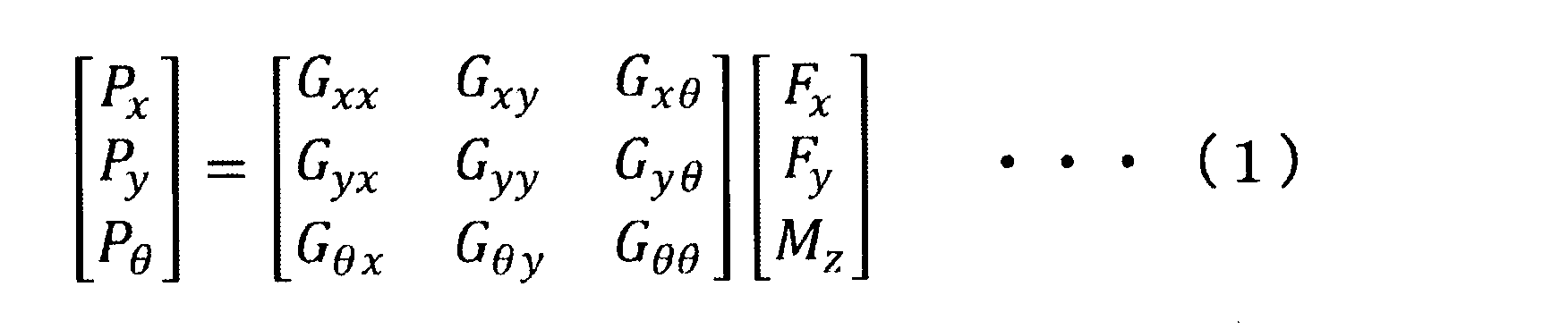

ここで、G(f)は、荷重伝達関数行列である。
ここで、上記加振力Fと計測荷重Pの関係は、図1に示す回転ドラム11と接触して従動回転しているタイヤ2を保持するタイヤ軸4に発生するタイヤ変動荷重(タイヤRFV、タイヤTFVおよびタイヤLFV)とロードセル12でそれぞれ測定されたタイヤ変動荷重波形(タイヤRFV波形、タイヤTFV波形およびタイヤLFV波形)の関係に通ずるものである。
また、上記加振力Fと加速度Xの関係は、下記式(3)または式(5)で表される。



ここで、H(f)は、加速度伝達関数行列である。
ここで、上記加振力Fと加速度Xの関係は、図1に示す回転ドラム11と接触して従動回転しているタイヤ2を保持するタイヤ軸4に発生するタイヤ変動荷重(タイヤRFV、タイヤTFVおよびタイヤLFV)とTUM1{(タイヤおよびリム)付き}の任意の位置に設置した加速度センサで測定した測定加速度の関係に通ずるものである。
予め上記式(2)のG(f)を実験により計測で求めておくことで、TUM1の固有振動数による共振の影響を補正する手法の一歩になると考えた。ここで、G(f)は、1次独立となるような加振力Fをn回与えた場合の計測荷重Pとの関係から、下記式(6)のように導出可能である。

また、上記式(6)より、1次独立となるような加振力Fを3条件与えた場合(n=3)の計測荷重Pとの概略関係は、下記式(7)および式(8)のように表現される。


次に、図8に記載するフローチャートおよび図3を用いて、上記式(8)に示す行列G(f)を導出する手順を説明する。
例えば、何も付加されていない第1の状態のタイヤユニフォミティマシン(TUM)について、図3Aに示す3箇所の1次独立の加振点を順次加振し、図3Bに示す計測点の加速度、及びロードセル30、40による荷重を計測する(図8に記載する工程S-1)。ここで、図3Aに示す任意加振点の加振力fx、fy1、fy2を加えた場合におけるロードセル30、40で計測される計測荷重P(図4に示すPx1、Px2、Py 1、Py2)の関係は、それぞれfx、fy1、fy2の加振力を与えた3回の試験の伝達関数を用いると下記式(9)となる。

一方、基準位置20における加振力(Fx、Fy、Mz)と上述した加振力(fx、fy1、fy2)の間には、下記式(10)に示すような関係式が成立する。

したがって、上記式(9)は、下記式(11)のように表される。
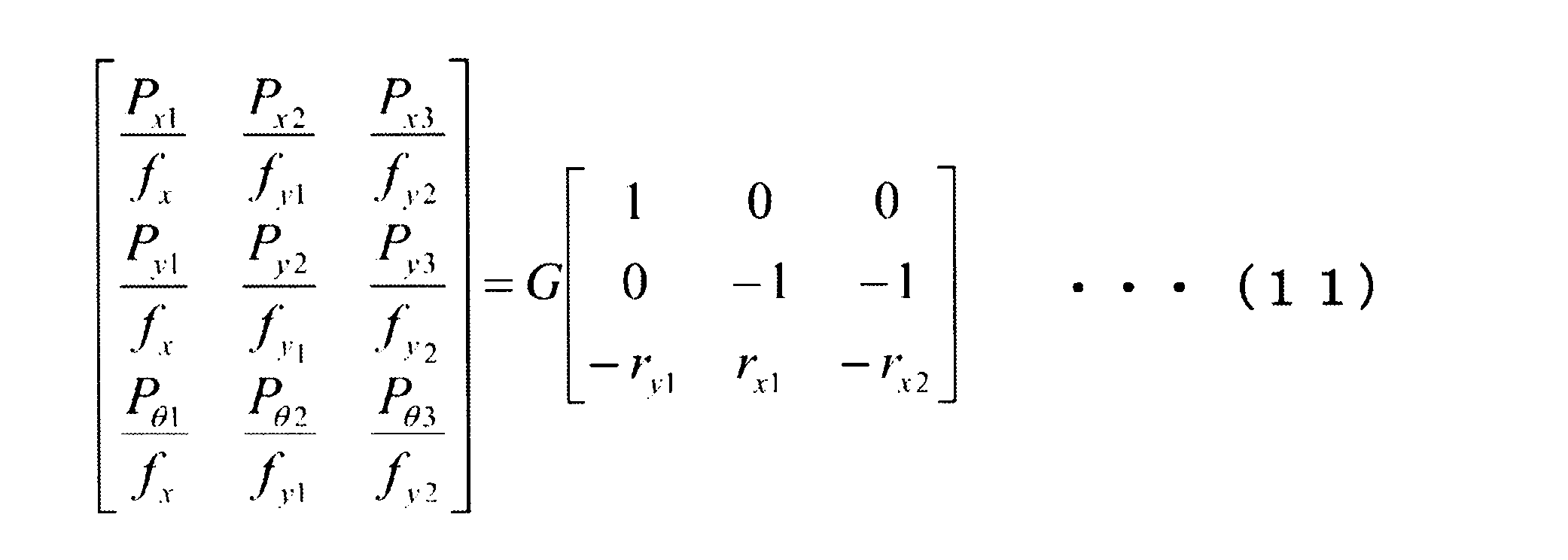
(荷重伝達関数行列G導出工程)
基準位置20に加振力を加えた場合における荷重伝達関数行列Gは、下記式(12)のようになる(図8に記載する工程S-2)。
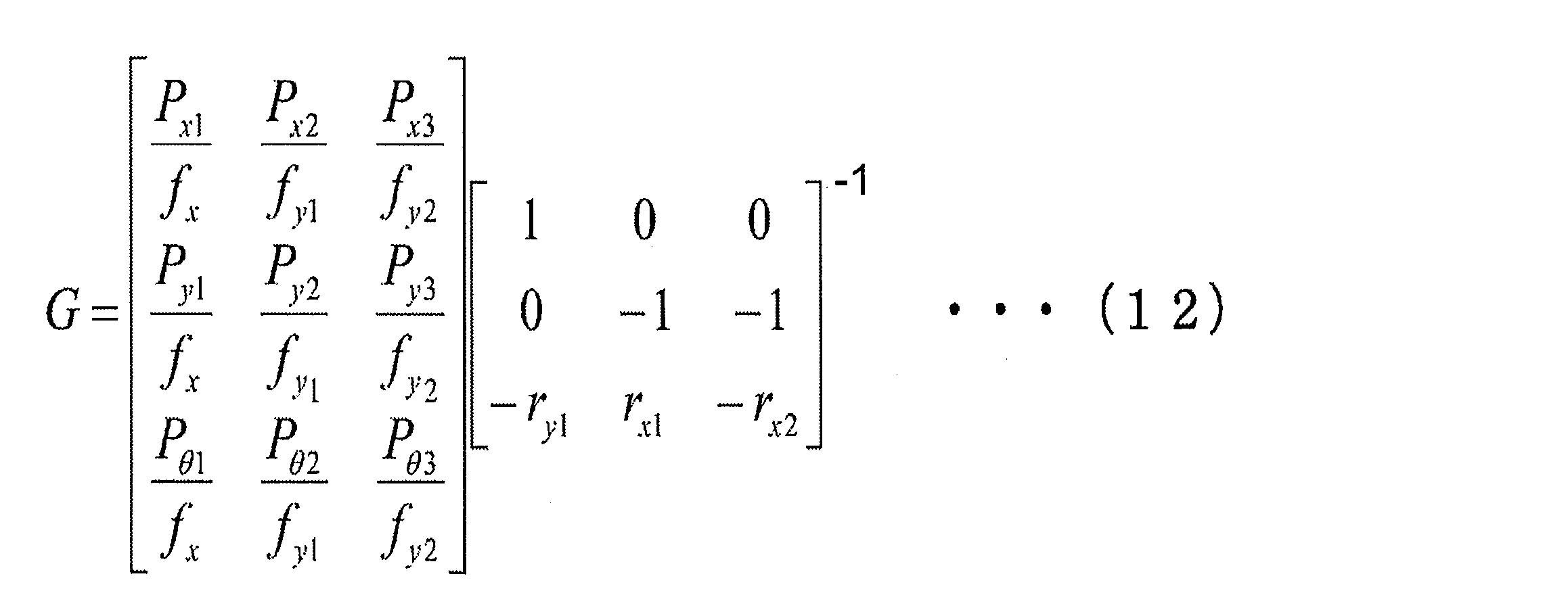
基準位置20に加振力を加えた場合における荷重伝達関数行列Gは、下記式(12)のようになる(図8に記載する工程S-2)。
上記式(12)における計測荷重P(Px、Py、Pθ)に関して、例えば図4に示す仮に定義したロードセル荷重計算点21、および4つの計測荷重(Px1、Px2、Py1、Py2)を用いると、下記式(13)~(15)のように定義することができる。


また、図3Aに示すような、TUM1の基準位置20に対して1次独立となるような加振力fx、fy1、fy2を加えた場合に、基準位置20におけるX方向、Y方向およびθ方向の各加速度(すなわち、X、Yおよびθのそれぞれ時間による2階微分)は、上記式(4)および上記式(10)の関係から下記式(16)のようになる。
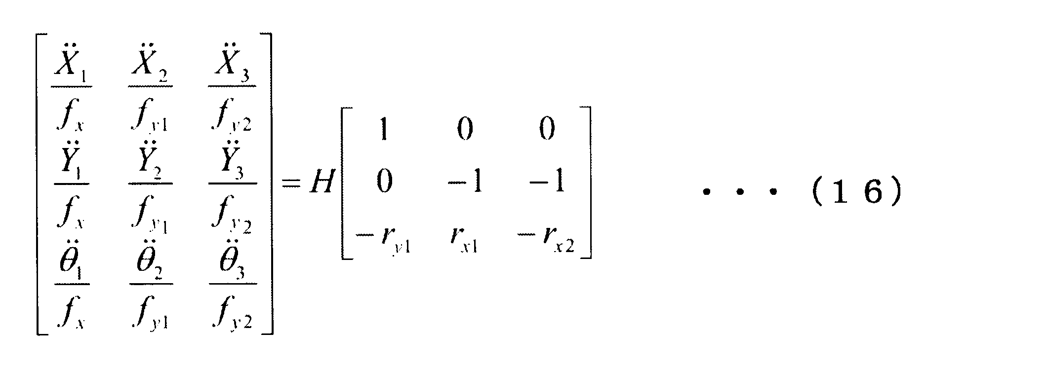
ここで、基準位置20の加速度と上記3点(図3Bに示す任意計測点)の加速度の関係は、下記式(17)のように表される。

ここで、加速度ベクトル変換行列TX を下記式(18)のように定義する。

したがって、上記式(16)は下記式(19)のように座標変換することができる。

(加速度伝達関数行列H導出工程)
基準位置20に加振力を加えた場合における基準位置20の加速度伝達関数行列Hは、上記式(5)および上記式(19)より、下記式(20)のように導出される(図8に記載する工程S-3)。
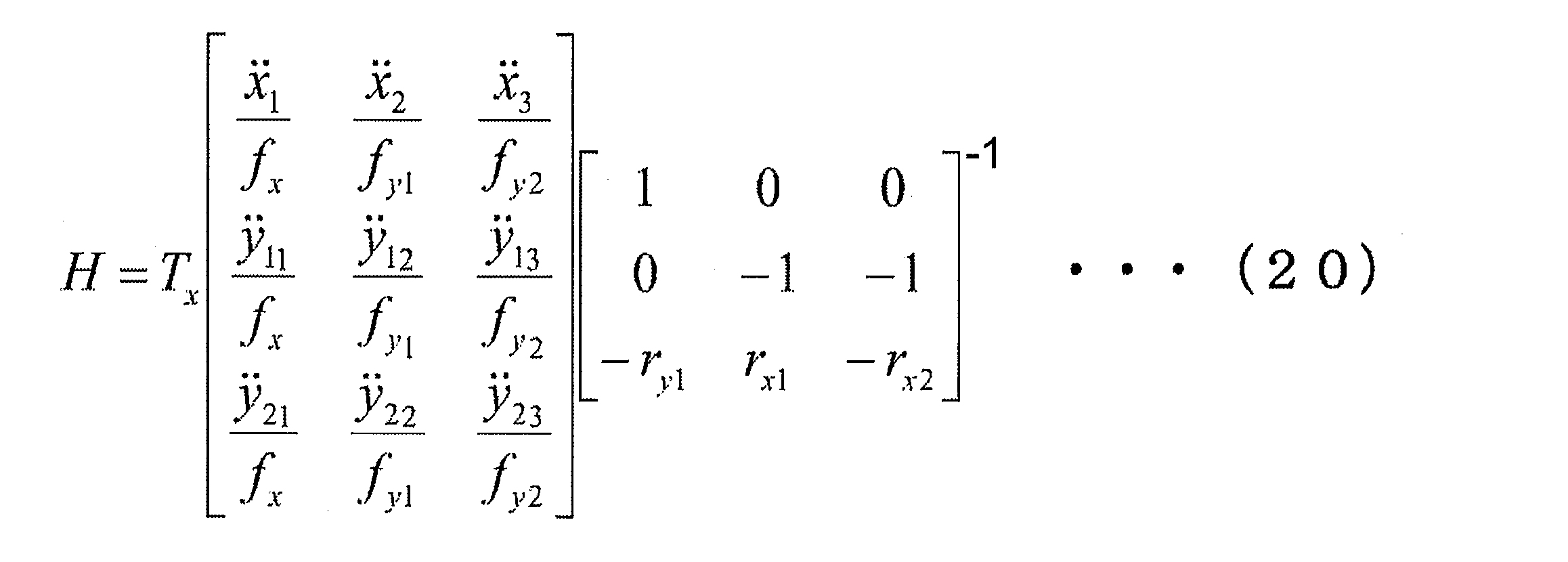
基準位置20に加振力を加えた場合における基準位置20の加速度伝達関数行列Hは、上記式(5)および上記式(19)より、下記式(20)のように導出される(図8に記載する工程S-3)。
以上により、タイヤユニフォミティマシン(TUM)1に何も付加されていない第1の状態のTUM1の固有振動特性を予め計測することが可能である。
なお、本実施形態においては、図3Aに示すように、基準位置20に対して1次独立となるような加振力fx、fy1、fy2を加えた場合におけるロードセル30、40で計測される計測荷重Pの関係より、図3Bに示すように、前記加振力が加えられた位置とは別の任意の位置に設置した3つの加速度センサで測定したx方向、y1方向およびy2方向の各加速度(すなわち、x、y1およびy2のそれぞれ時間による2階微分)の関係より、基準位置20に加振力を加えた場合における基準位置20の加速度伝達関数行列Hを導出する例について説明したが、必ずしもこれに限定されるものではない。
また、本実施形態においては、1次独立となるような加振力fx、fy1、fy2を与えた場合の計測荷重Pとの関係について説明したが、これに必ずしも限定されるものではなく、1次独立となるような、少なくとも3条件以上の加振を行い、その際の計測荷重Pとの関係を導出すればよい。
また、本実施形態においては、装置固有振動特性計測工程は、上述したように、タイヤユニフォミティマシン(TUM)1に何も付加されていない第1の状態のTUM1の固有振動特性を予め計測する例について説明したが、これに必ずしも限定されるものではない。例えば、TUM1に任意の質量体が取り付けられた第2の状態、TUM1に任意の質量体として実際のリム、または、前記実際のリムと同一仕様のリムが取り付けられた第3の状態、および、TUM1に任意の質量体として第3の状態に加えてさらに実際のタイヤ、または、前記実際のタイヤと同一仕様のタイヤが取り付けられた第4の状態のうちのいずれか一つの状態のTUM1の固有振動特性を予め計測する構成も可能である。次に、導出した荷重伝達関数行列G、加速度伝達関数行列Hを信号処理演算部15に記憶しておく。さらに、任意の質量体の質量m0、慣性モーメントI0および基準位置から任意の質量体の重心位置までの距離s0も信号処理演算部15に記憶しておく。ただし、任意の質量体が付加されていない場合は、m0、I0およびs0は、すべて「0」となる(図8に記載する工程S-4)。
(補正伝達関数Z導出工程)
上述した装置固有振動特性計測工程において、タイヤユニフォミティマシン(TUM)1に何も付加されていない第1の状態からTUM1に任意の質量体が取り付けられた第2の状態になると、取り付けられた任意の質量体の質量m0、任意の質量体の重心回り(θ 方向)の慣性モーメントI0の影響を受けて、上記式(8)に示す荷重伝達関数行列G(f){以降、単に「荷重伝達関数G」、「伝達関数行列G」、「伝達関数G」、「G」とも称す}は、変化する。また、上記第3の状態や上記第4の状態の場合の伝達関数Gも、上記第1の状態の場合の伝達関数Gから変化する。すなわち、任意の質量体としての中身が変化すれば、上述した装置固有振動特性計測工程における伝達関数Gも変化する。当然、上記第1~第4の状態のいずれか一つの状態から、上記実際のタイヤと上記実際のリムが取り付けられた状態に変移すれば、伝達関数Gも変化する。この場合の伝達関数Gを改めて、後述するような変移荷重伝達関数行列G´(f){以降、単に「変移荷重伝達関数G´」、「変移伝達関数行列G´」、「変移伝達関数G´」、「G´」とも称す}と定義する。そこで、例えば上記第1~第4の状態のうちのいずれか一つの状態において、装置固有振動特性計測工程を1回実施しておきさえすれば、この計測工程により得られた荷重伝達関数行列Gを基にして、計算により変移荷重伝達関数行列G´(詳細は、後記する)を算出し、さらに任意加振点から基準位置20へ座標変換された加振力Fx、Fy、Mzを加振力ベクトル変換行列Tfe導出工程により、前記基準位置20から前記実際のタイヤ2と前記回転ドラム11が接触する任意の接触部27または前記実際のリムの中心部における加振力に変換するための加振力ベクトル変換行列Tfeを導出し、G´Tfe{=G´´ (詳細は、後記する)}の逆数である補正伝達関数Zを導出することが可能な本発明の中核となる技術思想を着想した(詳細は、後述する)。以下に、上述した第1の状態の場合を中心に、実際のタイヤ2と実際のリム3が取り付けられた状態のTUM1の荷重伝達特性を補正する補正伝達関数Zを導出する手順について説明する。
上述した装置固有振動特性計測工程において、タイヤユニフォミティマシン(TUM)1に何も付加されていない第1の状態からTUM1に任意の質量体が取り付けられた第2の状態になると、取り付けられた任意の質量体の質量m0、任意の質量体の重心回り(θ 方向)の慣性モーメントI0の影響を受けて、上記式(8)に示す荷重伝達関数行列G(f){以降、単に「荷重伝達関数G」、「伝達関数行列G」、「伝達関数G」、「G」とも称す}は、変化する。また、上記第3の状態や上記第4の状態の場合の伝達関数Gも、上記第1の状態の場合の伝達関数Gから変化する。すなわち、任意の質量体としての中身が変化すれば、上述した装置固有振動特性計測工程における伝達関数Gも変化する。当然、上記第1~第4の状態のいずれか一つの状態から、上記実際のタイヤと上記実際のリムが取り付けられた状態に変移すれば、伝達関数Gも変化する。この場合の伝達関数Gを改めて、後述するような変移荷重伝達関数行列G´(f){以降、単に「変移荷重伝達関数G´」、「変移伝達関数行列G´」、「変移伝達関数G´」、「G´」とも称す}と定義する。そこで、例えば上記第1~第4の状態のうちのいずれか一つの状態において、装置固有振動特性計測工程を1回実施しておきさえすれば、この計測工程により得られた荷重伝達関数行列Gを基にして、計算により変移荷重伝達関数行列G´(詳細は、後記する)を算出し、さらに任意加振点から基準位置20へ座標変換された加振力Fx、Fy、Mzを加振力ベクトル変換行列Tfe導出工程により、前記基準位置20から前記実際のタイヤ2と前記回転ドラム11が接触する任意の接触部27または前記実際のリムの中心部における加振力に変換するための加振力ベクトル変換行列Tfeを導出し、G´Tfe{=G´´ (詳細は、後記する)}の逆数である補正伝達関数Zを導出することが可能な本発明の中核となる技術思想を着想した(詳細は、後述する)。以下に、上述した第1の状態の場合を中心に、実際のタイヤ2と実際のリム3が取り付けられた状態のTUM1の荷重伝達特性を補正する補正伝達関数Zを導出する手順について説明する。
次に、補正伝達関数Z導出工程において、基準位置における質量行列M導出工程(図8に記載する工程S-5)、加振力ベクトル変換行列Tfe導出工程(図8に記載する工程S-6)および補正伝達関数Zとしての第1の補正伝達関数Z1を導出する補正伝達関数Z導出工程(図8に記載する工程S-7)について詳述する。
(基準位置における質量行列M導出工程)
基準位置20における質量行列Mの導出方法は、まず基準位置20におけるX方向、Y方向およびθ方向の各加速度(すなわち、X、Yおよびθのそれぞれ時間による2階微分)を図5に示す付加質量体の重心位置25に座標変換し、付加質量体の重心周りの質量行列Mcと掛け合わせて荷重を算出する。ここで、付加質量体とは、TUMに装着する質量体を意味し、具体的には、実際に計測するタイヤ、リムなどの質量体または任意の質量体を意味する。そして、再び付加質量体の重心位置25から基準位置20へ変換し、基準位置20における質量行列Mが導出される(図8に記載する工程S-5)。図5に示す例の場合、基準位置20における荷重の関係は、下記式(21)のようになる。ここで、mは付加質量体の質量、Iは付加質量体の重心回りの慣性モーメント、sは基準位置20から付加質量体の重心位置25までの距離を示す。

基準位置20における質量行列Mの導出方法は、まず基準位置20におけるX方向、Y方向およびθ方向の各加速度(すなわち、X、Yおよびθのそれぞれ時間による2階微分)を図5に示す付加質量体の重心位置25に座標変換し、付加質量体の重心周りの質量行列Mcと掛け合わせて荷重を算出する。ここで、付加質量体とは、TUMに装着する質量体を意味し、具体的には、実際に計測するタイヤ、リムなどの質量体または任意の質量体を意味する。そして、再び付加質量体の重心位置25から基準位置20へ変換し、基準位置20における質量行列Mが導出される(図8に記載する工程S-5)。図5に示す例の場合、基準位置20における荷重の関係は、下記式(21)のようになる。ここで、mは付加質量体の質量、Iは付加質量体の重心回りの慣性モーメント、sは基準位置20から付加質量体の重心位置25までの距離を示す。
よって、基準位置20における質量行列Mは、下記式(22)のようになる。

なお、付加質量体の重心位置25が基準位置20よりも下にある場合は、sの値が負になる。
本補正法において、基準位置20における質量行列Mを導出する際は、上記第1、第2、第3および第4の状態のような任意の質量体の重心位置の質量行列と実際に装着するタイヤとリムを合わせた重心位置の質量行列の差分を考慮して質量行列Mを算出する必要がある。そのため、最終的に演算に使用される基準位置20の質量行列Mは、下記式(23)のようになる。

ここで、
(第1の状態の場合)
・実際に計測するタイヤとリムを合わせた質量をm1、
・実際に計測するタイヤとリムを合わせた重心回り(θ方向)の慣性モーメントをI1、
・基準位置20から実際に計測するタイヤとリムを合わせた重心位置までの距離をs1 とする。
・TUM1に取り付けられた任意の質量体をm0、
・任意の質量体の重心回り(θ方向)の慣性モーメントをI0、
・基準位置20から任意の質量体の重心位置25までの距離をs0とする。
但し、TUM1に何も付加されていないため、上記式(21)で表されるm0、I0、s0は0とする。
(第2の状態の場合)
・実際に計測するタイヤとリムを合わせた質量をm1、
・実際に計測するタイヤとリムを合わせた重心回り(θ方向)の慣性モーメントをI1、
・基準位置20から実際に計測するタイヤとリムを合わせた重心位置までの距離をs1 とする。
・TUM1に取り付けられた任意の質量体をm0、
・任意の質量体の重心回り(θ方向)の慣性モーメントをI0、
・基準位置20から任意の質量体の重心位置25までの距離をs0とする。
(第3の状態の場合)
・実際に計測するタイヤとリムを合わせた質量をm1、
・実際に計測するタイヤとリムを合わせた重心回り(θ方向)の慣性モーメントをI1、
・基準位置20から実際に計測するタイヤとリムを合わせた重心位置までの距離をs1 とする。
・TUM1に取り付けられた任意の質量体としての実際に計測するリム、または、前記実際に計測するリムと同一仕様のリムの質量体をm0、
・上記リムの重心回り(θ方向)の慣性モーメントをI0、
・基準位置20から上記リムの重心位置25までの距離をs0とする。
(第4の状態の場合)
・実際に計測するタイヤとリムを合わせた質量をm1、
・実際に計測するタイヤとリムを合わせた重心回り(θ方向)の慣性モーメントをI1、
・基準位置20から実際に計測するタイヤとリムを合わせた重心位置までの距離をs1 とする。
・TUM1に取り付けられた、上記第3の状態(実際に計測するリム、または、実際に計測するリムと同一仕様のリム)にさらに付加された実際に計測するタイヤ、または、前記実際に計測するタイヤと同一仕様のタイヤを合わせた質量をm0、
・上記リムと上記タイヤを合わせた重心回り(θ方向)の慣性モーメントをI0、
・基準位置20から上記リムと上記タイヤを合わせた重心位置までの距離をs0とする。
(第1の状態の場合)
・実際に計測するタイヤとリムを合わせた質量をm1、
・実際に計測するタイヤとリムを合わせた重心回り(θ方向)の慣性モーメントをI1、
・基準位置20から実際に計測するタイヤとリムを合わせた重心位置までの距離をs1 とする。
・TUM1に取り付けられた任意の質量体をm0、
・任意の質量体の重心回り(θ方向)の慣性モーメントをI0、
・基準位置20から任意の質量体の重心位置25までの距離をs0とする。
但し、TUM1に何も付加されていないため、上記式(21)で表されるm0、I0、s0は0とする。
(第2の状態の場合)
・実際に計測するタイヤとリムを合わせた質量をm1、
・実際に計測するタイヤとリムを合わせた重心回り(θ方向)の慣性モーメントをI1、
・基準位置20から実際に計測するタイヤとリムを合わせた重心位置までの距離をs1 とする。
・TUM1に取り付けられた任意の質量体をm0、
・任意の質量体の重心回り(θ方向)の慣性モーメントをI0、
・基準位置20から任意の質量体の重心位置25までの距離をs0とする。
(第3の状態の場合)
・実際に計測するタイヤとリムを合わせた質量をm1、
・実際に計測するタイヤとリムを合わせた重心回り(θ方向)の慣性モーメントをI1、
・基準位置20から実際に計測するタイヤとリムを合わせた重心位置までの距離をs1 とする。
・TUM1に取り付けられた任意の質量体としての実際に計測するリム、または、前記実際に計測するリムと同一仕様のリムの質量体をm0、
・上記リムの重心回り(θ方向)の慣性モーメントをI0、
・基準位置20から上記リムの重心位置25までの距離をs0とする。
(第4の状態の場合)
・実際に計測するタイヤとリムを合わせた質量をm1、
・実際に計測するタイヤとリムを合わせた重心回り(θ方向)の慣性モーメントをI1、
・基準位置20から実際に計測するタイヤとリムを合わせた重心位置までの距離をs1 とする。
・TUM1に取り付けられた、上記第3の状態(実際に計測するリム、または、実際に計測するリムと同一仕様のリム)にさらに付加された実際に計測するタイヤ、または、前記実際に計測するタイヤと同一仕様のタイヤを合わせた質量をm0、
・上記リムと上記タイヤを合わせた重心回り(θ方向)の慣性モーメントをI0、
・基準位置20から上記リムと上記タイヤを合わせた重心位置までの距離をs0とする。
例えば、上記第1の状態の場合のように、実際に計測するタイヤとリムが付加された後の加振力F´、実際に計測するタイヤとリムが付加される前(すなわち、TUM1に何も付加されていない状態)の加振力F、質量行列M、TUM1の基準位置20の加速度を用いた関係は、下記式(24)で表される。これを簡易式で表すと下記式(25)のようになる。
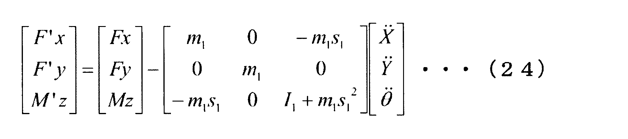

また、上述した式(4)は、上記加振力F´に対しても、下記式(26)のように成立する。

TUM1の基準位置20の加速度は、上記式(26)を下記式(27)のように展開し経由し整理すると、下記式(28)のように表される。


また、上述した式(2)は、上記加振力F´{すなわち、実際にタイヤ2およびリム3を取り付けた状態でのタイヤユニフォミティ(タイヤ変動荷重)}に対しても、下記式(29)のように成立する。

上記式(29)を下記式(30)のように展開し経由し整理すると、下記式(31)のように表される。


すなわち、正確な(精度の高い)タイヤユニフォミティデータFとタイヤ軸側のハウジングに設置された力センサとしてのロードセルで測定され、所定の信号処理を施す{例えば、タイヤ2に回転ドラム11を押し付ける時の負荷(DC成分)を分離する、または、そのまま含有する(分離せず、そのまま含む)}ことにより得られたタイヤユニフォミティ波形Pとは、上記式(31)によって表現できることが分かる。
よって、上記式(31)中に記載される荷重伝達関数行列に関する項を下記式(32)を用いて、変移荷重伝達関数行列G´と表現する。

また、上記式(32)より、タイヤ2およびリム3がTUM1に取り付けられていない時(すなわち、第1の状態の場合に相当する時)の荷重伝達関数行列Gを基にして、実際のタイヤ2および実際のリム3がTUM1に取り付けられる時の変移荷重伝達関数行列G´が計算可能であることも分かる。
図7は図1に示す構造におけるTUM1の基準位置20の荷重伝達関数行列G、変移荷重伝達関数行列G´を説明するための説明図である。図7における基準データは、リムとタイヤを装着していない「第1の状態に相当する」TUMの荷重伝達関数行列G、推定対象の結果(解析結果)は実際のリムと実際のタイヤを装着したTUMの荷重伝達関数行列G、本発明による推定結果は上記基準データに本発明の補正手法を適用して実際のリムと実際のタイヤ装着時の変移荷重伝達関数行列G´を推定したものである。なお、図7の縦軸は、G、G´(応答倍率)を示し、横軸は、周波数を基準データの1次の固有振動数で無次元化して表示している。図7より、有限要素法(FEM)によるG(応答倍率)の解析結果と本発明のタイヤユニフォミティデータの補正方法によるG´(応答倍率)の推定結果が良く一致することが分かる。なお、この結果は、実際のタイヤと実際のリムを集中質量と仮定して解析したものである。
(加振力ベクトル変換行列Tfe導出工程)
図6は加振力を基準位置20から実際に計測する(実際の)タイヤと回転ドラムが接触する任意の接触部27における加振力に変換するための加振力ベクトル変換行列Tfe(図8に記載する工程S-6)を説明するための説明図である。
図6は加振力を基準位置20から実際に計測する(実際の)タイヤと回転ドラムが接触する任意の接触部27における加振力に変換するための加振力ベクトル変換行列Tfe(図8に記載する工程S-6)を説明するための説明図である。
図6のような場合を例にあげると、基準位置20の加振力と実際に計測する(実際の)タイヤと回転ドラムが接触する任意の接触部27における加振力の関係は、下記式(33)のようになる。

ここで、fex、feyおよびmezは、タイヤ2と回転ドラム11が接触する任意の接触部27におけるx方向、y方向、および回転方向の加振力を示す。
よって、図6に示す数値ex1、ey1を用いると加振力ベクトル変換行列Tfeは、下記式(34)のようになる。

(補正伝達関数Z導出工程)
したがって、基準位置20から実際に計測する(実際の)タイヤと回転ドラムが接触する任意の接触部27における変移荷重伝達関数行列G´´は、下記式(35)のように表される。

したがって、基準位置20から実際に計測する(実際の)タイヤと回転ドラムが接触する任意の接触部27における変移荷重伝達関数行列G´´は、下記式(35)のように表される。
また、上記式(35)で表現される変移荷重伝達関数行列G´´の逆数を下記式(36)または下記式(37)のように、補正伝達関数Zと改めて設定する(図8に記載する工程S-7)。


ここで、補正伝達関数Zとしての第1の補正伝達関数Z1、第2の補正伝達関数Z2、第3の補正伝達関数Z3および第4の補正伝達関数Z4を以下のように定義する。
<第1の補正伝達関数Z1>
上述した第1の状態における装置固有振動特性計測工程で得られた荷重伝達関数行列Gと加速度伝達関数行列H、および、前記第1の状態と実際のリムと実際のタイヤを装着した状態との差分を考慮して上記式(23)から算出した質量行列Mを上記式(32)に代入し、実際のリムと実際のタイヤ装着時の変移荷重伝達関数行列G´を求める。そして、この変移荷重伝達関数行列G´を上記式(35)に代入し、実際のタイヤと回転ドラムが接触する任意の接触部における変移荷重伝達関数行列G´´を求める。この変移荷重伝達関数行列G´´は、前記第1の状態から実際のタイヤと実際のリムが付加されたことによる慣性力の増加およびTUM単体の固有振動数の影響を受け、実際のタイヤと回転ドラムが接触する任意の接触部におけるユニフォミティ波形(すなわち、ロードセルで計測した計測荷重)がどのような挙動(荷重伝達特性、応答)となるかを示す。したがって、この変移荷重伝達関数行列G´´の逆数(補正伝達関数Z)を下記式(38)に代入すれば、正確な(精度の高い)タイヤユニフォミティデータFが得られる(すなわち、上記影響を排除するように補正できる)。この場合の補正伝達関数Zを第1の補正伝達関数Z1と称す。
<第2の補正伝達関数Z2>
上述した第2の状態における装置固有振動特性計測工程で得られた荷重伝達関数行列Gと加速度伝達関数行列H、および、前記第2の状態と実際のリムと実際のタイヤを装着した状態との差分を考慮して上記式(23)から算出した質量行列Mを上記式(32)に代入し、実際のリムと実際のタイヤ装着時の変移荷重伝達関数行列G´を求める。そして、この変移荷重伝達関数行列G´を上記式(35)に代入し、実際のタイヤと回転ドラムが接触する任意の接触部における変移荷重伝達関数行列G´´を求める。この変移荷重伝達関数行列G´´は、前記第2の状態から実際のタイヤと実際のリムが付加されたことによる慣性力の増加およびTUM単体の固有振動数の影響を受け、実際のタイヤと回転ドラムが接触する任意の接触部におけるユニフォミティ波形(すなわち、ロードセルで計測した計測荷重)がどのような挙動(荷重伝達特性、応答)となるかを示す。したがって、この変移荷重伝達関数行列G´´の逆数(補正伝達関数Z)を下記式(38)に代入すれば、正確な(精度の高い)タイヤユニフォミティデータFが得られる(すなわち、上記影響を排除するように補正できる)。この場合の補正伝達関数Zを第2の補正伝達関数Z2と称す。
<第3の補正伝達関数Z3>
上述した第3の状態における装置固有振動特性計測工程で得られた荷重伝達関数行列Gと加速度伝達関数行列H、および、前記第3の状態と実際のリムと実際のタイヤを装着した状態との差分を考慮して上記式(23)から算出した質量行列Mを上記式(32)に代入し、実際のリムと実際のタイヤ装着時の変移荷重伝達関数行列G´を求める。そして、この変移荷重伝達関数行列G´を上記式(35)に代入し、実際のタイヤと回転ドラムが接触する任意の接触部における変移荷重伝達関数行列G´´を求める。この変移荷重伝達関数行列G´´は、前記第3の状態から実際のタイヤと実際のリムが付加されたことによる慣性力の増加およびTUM単体の固有振動数の影響を受け、実際のタイヤと回転ドラムが接触する任意の接触部におけるユニフォミティ波形(すなわち、ロードセルで計測した計測荷重)がどのような挙動(荷重伝達特性、応答)となるかを示す。したがって、この変移荷重伝達関数行列G´´の逆数(補正伝達関数Z)を下記式(38)に代入すれば、正確な(精度の高い)タイヤユニフォミティデータFが得られる(すなわち、上記影響を排除するように補正できる)。この場合の補正伝達関数Zを第3の補正伝達関数Z3と称す。
<第4の補正伝達関数Z4>
上述した第4の状態における装置固有振動特性計測工程で得られた荷重伝達関数行列Gと加速度伝達関数行列H、および、前記第4の状態と実際のリムと実際のタイヤを装着した状態との差分を考慮して上記式(23)から算出した質量行列Mを上記式(32)に代入し、実際のリムと実際のタイヤ装着時の変移荷重伝達関数行列G´を求める。そして、この変移荷重伝達関数行列G´を上記式(35)に代入し、実際のタイヤと回転ドラムが接触する任意の接触部における変移荷重伝達関数行列G´´を求める。この変移荷重伝達関数行列G´´は、前記第4の状態から実際のタイヤと実際のリムが付加されたことによる慣性力の増加およびTUM単体の固有振動数の影響を受け、実際のタイヤと回転ドラムが接触する任意の接触部におけるユニフォミティ波形(すなわち、ロードセルで計測した計測荷重)がどのような挙動(荷重伝達特性、応答)となるかを示す。したがって、この変移荷重伝達関数行列G´´の逆数(補正伝達関数Z)を下記式(38)に代入すれば、正確な(精度の高い)タイヤユニフォミティデータFが得られる(すなわち、上記影響を排除するように補正できる)。この場合の補正伝達関数Zを第4の補正伝達関数Z4と称す。なお、前記第4の状態と実際のリムと実際のタイヤを装着した状態との差分は実質的にゼロであるため、上記式(32)において、実際のリムと実際のタイヤ装着時の変移荷重伝達関数行列G´と、前記第4の状態における装置固有振動特性計測工程で得られた荷重伝達関数行列Gは、同等になる。
<第1の補正伝達関数Z1>
上述した第1の状態における装置固有振動特性計測工程で得られた荷重伝達関数行列Gと加速度伝達関数行列H、および、前記第1の状態と実際のリムと実際のタイヤを装着した状態との差分を考慮して上記式(23)から算出した質量行列Mを上記式(32)に代入し、実際のリムと実際のタイヤ装着時の変移荷重伝達関数行列G´を求める。そして、この変移荷重伝達関数行列G´を上記式(35)に代入し、実際のタイヤと回転ドラムが接触する任意の接触部における変移荷重伝達関数行列G´´を求める。この変移荷重伝達関数行列G´´は、前記第1の状態から実際のタイヤと実際のリムが付加されたことによる慣性力の増加およびTUM単体の固有振動数の影響を受け、実際のタイヤと回転ドラムが接触する任意の接触部におけるユニフォミティ波形(すなわち、ロードセルで計測した計測荷重)がどのような挙動(荷重伝達特性、応答)となるかを示す。したがって、この変移荷重伝達関数行列G´´の逆数(補正伝達関数Z)を下記式(38)に代入すれば、正確な(精度の高い)タイヤユニフォミティデータFが得られる(すなわち、上記影響を排除するように補正できる)。この場合の補正伝達関数Zを第1の補正伝達関数Z1と称す。
<第2の補正伝達関数Z2>
上述した第2の状態における装置固有振動特性計測工程で得られた荷重伝達関数行列Gと加速度伝達関数行列H、および、前記第2の状態と実際のリムと実際のタイヤを装着した状態との差分を考慮して上記式(23)から算出した質量行列Mを上記式(32)に代入し、実際のリムと実際のタイヤ装着時の変移荷重伝達関数行列G´を求める。そして、この変移荷重伝達関数行列G´を上記式(35)に代入し、実際のタイヤと回転ドラムが接触する任意の接触部における変移荷重伝達関数行列G´´を求める。この変移荷重伝達関数行列G´´は、前記第2の状態から実際のタイヤと実際のリムが付加されたことによる慣性力の増加およびTUM単体の固有振動数の影響を受け、実際のタイヤと回転ドラムが接触する任意の接触部におけるユニフォミティ波形(すなわち、ロードセルで計測した計測荷重)がどのような挙動(荷重伝達特性、応答)となるかを示す。したがって、この変移荷重伝達関数行列G´´の逆数(補正伝達関数Z)を下記式(38)に代入すれば、正確な(精度の高い)タイヤユニフォミティデータFが得られる(すなわち、上記影響を排除するように補正できる)。この場合の補正伝達関数Zを第2の補正伝達関数Z2と称す。
<第3の補正伝達関数Z3>
上述した第3の状態における装置固有振動特性計測工程で得られた荷重伝達関数行列Gと加速度伝達関数行列H、および、前記第3の状態と実際のリムと実際のタイヤを装着した状態との差分を考慮して上記式(23)から算出した質量行列Mを上記式(32)に代入し、実際のリムと実際のタイヤ装着時の変移荷重伝達関数行列G´を求める。そして、この変移荷重伝達関数行列G´を上記式(35)に代入し、実際のタイヤと回転ドラムが接触する任意の接触部における変移荷重伝達関数行列G´´を求める。この変移荷重伝達関数行列G´´は、前記第3の状態から実際のタイヤと実際のリムが付加されたことによる慣性力の増加およびTUM単体の固有振動数の影響を受け、実際のタイヤと回転ドラムが接触する任意の接触部におけるユニフォミティ波形(すなわち、ロードセルで計測した計測荷重)がどのような挙動(荷重伝達特性、応答)となるかを示す。したがって、この変移荷重伝達関数行列G´´の逆数(補正伝達関数Z)を下記式(38)に代入すれば、正確な(精度の高い)タイヤユニフォミティデータFが得られる(すなわち、上記影響を排除するように補正できる)。この場合の補正伝達関数Zを第3の補正伝達関数Z3と称す。
<第4の補正伝達関数Z4>
上述した第4の状態における装置固有振動特性計測工程で得られた荷重伝達関数行列Gと加速度伝達関数行列H、および、前記第4の状態と実際のリムと実際のタイヤを装着した状態との差分を考慮して上記式(23)から算出した質量行列Mを上記式(32)に代入し、実際のリムと実際のタイヤ装着時の変移荷重伝達関数行列G´を求める。そして、この変移荷重伝達関数行列G´を上記式(35)に代入し、実際のタイヤと回転ドラムが接触する任意の接触部における変移荷重伝達関数行列G´´を求める。この変移荷重伝達関数行列G´´は、前記第4の状態から実際のタイヤと実際のリムが付加されたことによる慣性力の増加およびTUM単体の固有振動数の影響を受け、実際のタイヤと回転ドラムが接触する任意の接触部におけるユニフォミティ波形(すなわち、ロードセルで計測した計測荷重)がどのような挙動(荷重伝達特性、応答)となるかを示す。したがって、この変移荷重伝達関数行列G´´の逆数(補正伝達関数Z)を下記式(38)に代入すれば、正確な(精度の高い)タイヤユニフォミティデータFが得られる(すなわち、上記影響を排除するように補正できる)。この場合の補正伝達関数Zを第4の補正伝達関数Z4と称す。なお、前記第4の状態と実際のリムと実際のタイヤを装着した状態との差分は実質的にゼロであるため、上記式(32)において、実際のリムと実際のタイヤ装着時の変移荷重伝達関数行列G´と、前記第4の状態における装置固有振動特性計測工程で得られた荷重伝達関数行列Gは、同等になる。
(タイヤユニフォミティデータ補正工程)
したがって、下記式(38)に示すように、実際にタイヤ2およびリム3をTUM1に取り付けた状態でタイヤユニフォミティ波形を力センサとしてのロードセルで測定し、上述した所定の信号処理を施し出力されるタイヤユニフォミティデータPに、上述した補正伝達関数Z導出工程で導出した上記式(36)または上記式(37)で表される補正伝達関数Z(例えば、第1の補正伝達関数Z1)を乗ずる演算処理を行なうことで、正確な(精度の高い)タイヤユニフォミティデータFが得られる(図8に記載する工程S-8、S-9)。

したがって、下記式(38)に示すように、実際にタイヤ2およびリム3をTUM1に取り付けた状態でタイヤユニフォミティ波形を力センサとしてのロードセルで測定し、上述した所定の信号処理を施し出力されるタイヤユニフォミティデータPに、上述した補正伝達関数Z導出工程で導出した上記式(36)または上記式(37)で表される補正伝達関数Z(例えば、第1の補正伝達関数Z1)を乗ずる演算処理を行なうことで、正確な(精度の高い)タイヤユニフォミティデータFが得られる(図8に記載する工程S-8、S-9)。
本発明のタイヤユニフォミティデータの補正方法は、上述したような各工程を有したことにより、過剰な剛性を有したTUM(タイヤユニフォミティマシン)を用いることなく、高速で回転する各種タイヤの高次成分の周波数に対しても正確な(精度の高い)タイヤユニフォミティデータを求めることが可能となる。
以上、本発明の実施形態を説明したが、具体例を例示したに過ぎず、特に本発明を限定するものではなく、具体的構成などは、適宜設計変更可能である。また、発明の実施の形態に記載された、作用及び効果は、本発明から生じる最も好適な作用及び効果を列挙したに過ぎず、本発明による作用及び効果は、本発明の実施の形態に記載されたものに限定されるものではない。
本出願を詳細にまた特定の実施態様を参照して説明したが、本発明の精神と範囲を逸脱することなく様々な変更や修正を加えることができることは当業者にとって明らかである。
本出願は、2018年9月3日出願の日本特許出願(特願2018-164546)に基づくものであり、その内容はここに参照として取り込まれる。
本出願は、2018年9月3日出願の日本特許出願(特願2018-164546)に基づくものであり、その内容はここに参照として取り込まれる。
1 TUM
2 タイヤ
3 リム
4 タイヤ軸
5、6、8、9 軸受部
7 ハウジング
10 駆動軸
11 回転ドラム
12、30、40 ロードセル
13 架台
15 信号処理演算部
16 タイヤユニフォミティ測定部
20 基準位置
21 ロードセル荷重計算点
25 付加質量体の重心位置
27 接触部
2 タイヤ
3 リム
4 タイヤ軸
5、6、8、9 軸受部
7 ハウジング
10 駆動軸
11 回転ドラム
12、30、40 ロードセル
13 架台
15 信号処理演算部
16 タイヤユニフォミティ測定部
20 基準位置
21 ロードセル荷重計算点
25 付加質量体の重心位置
27 接触部
Claims (9)
- 回転ドラムと接触して従動回転しているタイヤを保持するタイヤ軸に発生するタイヤユニフォミティ波形を測定する前記タイヤ軸側のハウジングに設置した力センサと、前記力センサで測定したタイヤユニフォミティ波形に所定の信号処理を施し、タイヤユニフォミティデータとして出力する信号処理演算部と、を有するタイヤユニフォミティ測定部を備えたタイヤユニフォミティマシンにおける、タイヤユニフォミティデータの補正方法であって、
所定の状態における前記タイヤユニフォミティマシンの固有振動特性を予め計測し、
前記固有振動特性の計測結果を考慮に入れ、前記タイヤユニフォミティ波形を測定する対象のタイヤと当該タイヤに対応したリムが取り付けられた状態の前記タイヤユニフォミティマシンの荷重伝達特性を補正する補正伝達関数を導出し、
前記タイヤおよび前記リムを取り付けた状態で前記タイヤユニフォミティ波形を前記力センサで測定し、前記所定の信号処理を施し出力されるタイヤユニフォミティデータに、前記補正伝達関数を乗ずる演算処理を行なう、
ことを特徴とするタイヤユニフォミティデータの補正方法。 - 請求項1に記載のタイヤユニフォミティデータの補正方法において、
前記所定の状態は、前記タイヤユニフォミティマシンに質量体が取り付けられていない状態であることを特徴とするタイヤユニフォミティデータの補正方法。 - 請求項1に記載のタイヤユニフォミティデータの補正方法において、
前記所定の状態は、前記タイヤユニフォミティマシンに質量体が取り付けられている状態であることを特徴とするタイヤユニフォミティデータの補正方法。 - 請求項3に記載のタイヤユニフォミティデータの補正方法において、
前記質量体は、前記リム、または、前記リムと同一仕様のリムであることを特徴とするタイヤユニフォミティデータの補正方法。 - 請求項4に記載のタイヤユニフォミティデータの補正方法において、
前記質量体として、前記タイヤ、または、前記タイヤと同一仕様のタイヤがさらに付加されることを特徴とするタイヤユニフォミティデータの補正方法。 - 請求項1~5のいずれか1項に記載のタイヤユニフォミティデータの補正方法において、
前記固有振動特性の計測において、前記所定の状態の前記タイヤユニフォミティマシンの基準位置に対して1次独立となるような3条件以上の加振力を加えることを特徴とするタイヤユニフォミティデータの補正方法。 - 請求項6に記載のタイヤユニフォミティデータの補正方法において、
前記固有振動特性の計測において、前記加振力と前記力センサで測定した測定荷重の関係を示す荷重伝達関数行列を予め導出することを特徴とするタイヤユニフォミティデータの補正方法。 - 請求項7に記載のタイヤユニフォミティデータの補正方法において、
前記固有振動特性の計測において、前記加振力と前記加振力が加えられた位置とは別の位置に設置した加速度センサで測定した測定加速度の関係を示す加速度伝達関数行列を予め導出することを特徴とするタイヤユニフォミティデータの補正方法。 - 請求項8に記載のタイヤユニフォミティデータの補正方法において、
前記前記タイヤユニフォミティマシンにおける前記所定の状態並びに前記タイヤと前記リムを考慮に入れ、質量行列を導出し、
前記加振力を前記基準位置から前記タイヤと前記回転ドラムが接触する接触部における加振力に変換するための加振力ベクトル変換行列を導出し、
下記式(1)に基づいて前記補正伝達関数を導出することを特徴とするタイヤユニフォミティデータの補正方法。

G:荷重伝達関数行列
H:加速度伝達関数行列
M:質量行列
Tfe:加振力ベクトル変換行列
Applications Claiming Priority (2)
| Application Number | Priority Date | Filing Date | Title |
|---|---|---|---|
| JP2018164546A JP2020037299A (ja) | 2018-09-03 | 2018-09-03 | タイヤユニフォミティデータの補正方法およびタイヤユニフォミティマシン |
| JP2018-164546 | 2018-09-03 |
Publications (1)
| Publication Number | Publication Date |
|---|---|
| WO2020050125A1 true WO2020050125A1 (ja) | 2020-03-12 |
Family
ID=69721827
Family Applications (1)
| Application Number | Title | Priority Date | Filing Date |
|---|---|---|---|
| PCT/JP2019/033907 Ceased WO2020050125A1 (ja) | 2018-09-03 | 2019-08-29 | タイヤユニフォミティデータの補正方法 |
Country Status (3)
| Country | Link |
|---|---|
| JP (1) | JP2020037299A (ja) |
| TW (1) | TW202016524A (ja) |
| WO (1) | WO2020050125A1 (ja) |
Cited By (3)
| Publication number | Priority date | Publication date | Assignee | Title |
|---|---|---|---|---|
| CN111912631A (zh) * | 2019-05-08 | 2020-11-10 | 株式会社神户制钢所 | 轮胎均匀性数据的校正方法及轮胎均匀性试验机 |
| CN112326272A (zh) * | 2021-01-06 | 2021-02-05 | 永一橡胶有限公司 | 一种反包胶囊压力均匀性检测装置及检测方法 |
| CN112345273A (zh) * | 2020-09-29 | 2021-02-09 | 中策橡胶集团有限公司 | 一种轮胎高速均匀性设备控制胎监测方法 |
Citations (6)
| Publication number | Priority date | Publication date | Assignee | Title |
|---|---|---|---|---|
| JPH0618352A (ja) * | 1992-06-30 | 1994-01-25 | Yokohama Rubber Co Ltd:The | タイヤユニフォミティー測定方法及びその装置 |
| US6584836B1 (en) * | 2001-12-10 | 2003-07-01 | The Goodyear Tire & Rubber Company | Bias method for identifying and removing machine contribution to test data |
| JP2003194653A (ja) * | 2001-12-26 | 2003-07-09 | Toshiba Mach Co Ltd | 回転体の不釣り合いの測定方法並びに修正方法およびその装置 |
| JP2007121042A (ja) * | 2005-10-26 | 2007-05-17 | Kobe Steel Ltd | タイヤ試験機及びタイヤ試験の方法 |
| JP2008058082A (ja) * | 2006-08-30 | 2008-03-13 | Kobe Steel Ltd | タイヤ試験方法及びタイヤ試験装置 |
| JP2013221792A (ja) * | 2012-04-13 | 2013-10-28 | Kobe Steel Ltd | タイヤバランス検査装置の校正方法及びタイヤバランス検査装置 |
-
2018
- 2018-09-03 JP JP2018164546A patent/JP2020037299A/ja active Pending
-
2019
- 2019-08-29 WO PCT/JP2019/033907 patent/WO2020050125A1/ja not_active Ceased
- 2019-09-02 TW TW108131492A patent/TW202016524A/zh unknown
Patent Citations (6)
| Publication number | Priority date | Publication date | Assignee | Title |
|---|---|---|---|---|
| JPH0618352A (ja) * | 1992-06-30 | 1994-01-25 | Yokohama Rubber Co Ltd:The | タイヤユニフォミティー測定方法及びその装置 |
| US6584836B1 (en) * | 2001-12-10 | 2003-07-01 | The Goodyear Tire & Rubber Company | Bias method for identifying and removing machine contribution to test data |
| JP2003194653A (ja) * | 2001-12-26 | 2003-07-09 | Toshiba Mach Co Ltd | 回転体の不釣り合いの測定方法並びに修正方法およびその装置 |
| JP2007121042A (ja) * | 2005-10-26 | 2007-05-17 | Kobe Steel Ltd | タイヤ試験機及びタイヤ試験の方法 |
| JP2008058082A (ja) * | 2006-08-30 | 2008-03-13 | Kobe Steel Ltd | タイヤ試験方法及びタイヤ試験装置 |
| JP2013221792A (ja) * | 2012-04-13 | 2013-10-28 | Kobe Steel Ltd | タイヤバランス検査装置の校正方法及びタイヤバランス検査装置 |
Cited By (4)
| Publication number | Priority date | Publication date | Assignee | Title |
|---|---|---|---|---|
| CN111912631A (zh) * | 2019-05-08 | 2020-11-10 | 株式会社神户制钢所 | 轮胎均匀性数据的校正方法及轮胎均匀性试验机 |
| CN112345273A (zh) * | 2020-09-29 | 2021-02-09 | 中策橡胶集团有限公司 | 一种轮胎高速均匀性设备控制胎监测方法 |
| CN112326272A (zh) * | 2021-01-06 | 2021-02-05 | 永一橡胶有限公司 | 一种反包胶囊压力均匀性检测装置及检测方法 |
| CN112326272B (zh) * | 2021-01-06 | 2021-03-12 | 永一橡胶有限公司 | 一种反包胶囊压力均匀性检测装置及检测方法 |
Also Published As
| Publication number | Publication date |
|---|---|
| TW202016524A (zh) | 2020-05-01 |
| JP2020037299A (ja) | 2020-03-12 |
Similar Documents
| Publication | Publication Date | Title |
|---|---|---|
| JP4887146B2 (ja) | ころがり要素軸受に作用する接触力ベクトルを決定するための方法及びそのためのセンサ装置 | |
| CN105406797A (zh) | 控制装置和减速机系统 | |
| KR101505345B1 (ko) | 구름 저항 시험기에 구비된 다분력 검출기의 교정 방법 | |
| JP5316151B2 (ja) | 動力系の試験装置及びその制御方法 | |
| TW200944770A (en) | Tire testing machine and method for testing tire | |
| US20200355577A1 (en) | Method for correcting tire uniformity data and tire uniformity machine | |
| JP2020037299A (ja) | タイヤユニフォミティデータの補正方法およびタイヤユニフォミティマシン | |
| WO2013191055A1 (ja) | 転がり抵抗試験機に備えられた多分力検出器の校正方法 | |
| JP5904851B2 (ja) | タイヤバランス検査装置の校正方法及びタイヤバランス検査装置 | |
| JP2019020243A (ja) | 車両駆動系試験システム及び車両駆動系試験方法 | |
| JP5790339B2 (ja) | 動力伝達系の試験装置 | |
| WO2012165442A1 (ja) | タイヤバランス試験方法及びタイヤバランス試験機 | |
| CN113656994B (zh) | 一种汽车悬置系统的悬置力获取方法及装置 | |
| JP2003302305A (ja) | 不釣合い修正方法および装置 | |
| JP2011107051A (ja) | パワートレインの試験システム | |
| CN115391916A (zh) | 一种车轮双轴疲劳仿真分析方法、装置、设备及介质 | |
| Vinattieri et al. | Target setting and structural design of an EPS-in-the-Loop test bench for steering feeling simulation | |
| JP6443237B2 (ja) | ステアリング状態推定装置及びプログラム | |
| JP5888371B2 (ja) | 揺動式ダイナモメータシステム及びその制御方法 | |
| JP5160734B2 (ja) | 車軸多分力計測方法 | |
| JP2009222539A (ja) | 特性解析装置及び特性解析プログラム | |
| CN121655368B (zh) | 机载环境下直升机传动轴位移测试方法、装置、设备及介质 | |
| JP6488611B2 (ja) | 車両用モーメント解析装置、車両用モーメント解析方法および車両用モーメント解析プログラム | |
| JP6463174B2 (ja) | 制御装置及び減速機システム | |
| JP7175445B2 (ja) | タイヤ試験装置の軸トルク制御器 |
Legal Events
| Date | Code | Title | Description |
|---|---|---|---|
| 121 | Ep: the epo has been informed by wipo that ep was designated in this application |
Ref document number: 19856917 Country of ref document: EP Kind code of ref document: A1 |
|
| NENP | Non-entry into the national phase |
Ref country code: DE |
|
| 122 | Ep: pct application non-entry in european phase |
Ref document number: 19856917 Country of ref document: EP Kind code of ref document: A1 |