WO2020049915A1 - クライオポンプおよびクライオポンプの監視方法 - Google Patents
クライオポンプおよびクライオポンプの監視方法 Download PDFInfo
- Publication number
- WO2020049915A1 WO2020049915A1 PCT/JP2019/030301 JP2019030301W WO2020049915A1 WO 2020049915 A1 WO2020049915 A1 WO 2020049915A1 JP 2019030301 W JP2019030301 W JP 2019030301W WO 2020049915 A1 WO2020049915 A1 WO 2020049915A1
- Authority
- WO
- WIPO (PCT)
- Prior art keywords
- stage
- cryopanel
- cryopump
- refrigerator
- gas
- Prior art date
- Legal status (The legal status is an assumption and is not a legal conclusion. Google has not performed a legal analysis and makes no representation as to the accuracy of the status listed.)
- Ceased
Links
Images





Classifications
-
- F—MECHANICAL ENGINEERING; LIGHTING; HEATING; WEAPONS; BLASTING
- F04—POSITIVE - DISPLACEMENT MACHINES FOR LIQUIDS; PUMPS FOR LIQUIDS OR ELASTIC FLUIDS
- F04B—POSITIVE-DISPLACEMENT MACHINES FOR LIQUIDS; PUMPS
- F04B37/00—Pumps having pertinent characteristics not provided for in, or of interest apart from, groups F04B25/00 - F04B35/00
- F04B37/06—Pumps having pertinent characteristics not provided for in, or of interest apart from, groups F04B25/00 - F04B35/00 for evacuating by thermal means
- F04B37/08—Pumps having pertinent characteristics not provided for in, or of interest apart from, groups F04B25/00 - F04B35/00 for evacuating by thermal means by condensing or freezing, e.g. cryogenic pumps
- F04B37/085—Regeneration of cryo-pumps
-
- F—MECHANICAL ENGINEERING; LIGHTING; HEATING; WEAPONS; BLASTING
- F04—POSITIVE - DISPLACEMENT MACHINES FOR LIQUIDS; PUMPS FOR LIQUIDS OR ELASTIC FLUIDS
- F04B—POSITIVE-DISPLACEMENT MACHINES FOR LIQUIDS; PUMPS
- F04B37/00—Pumps having pertinent characteristics not provided for in, or of interest apart from, groups F04B25/00 - F04B35/00
- F04B37/06—Pumps having pertinent characteristics not provided for in, or of interest apart from, groups F04B25/00 - F04B35/00 for evacuating by thermal means
- F04B37/08—Pumps having pertinent characteristics not provided for in, or of interest apart from, groups F04B25/00 - F04B35/00 for evacuating by thermal means by condensing or freezing, e.g. cryogenic pumps
-
- F—MECHANICAL ENGINEERING; LIGHTING; HEATING; WEAPONS; BLASTING
- F04—POSITIVE - DISPLACEMENT MACHINES FOR LIQUIDS; PUMPS FOR LIQUIDS OR ELASTIC FLUIDS
- F04B—POSITIVE-DISPLACEMENT MACHINES FOR LIQUIDS; PUMPS
- F04B37/00—Pumps having pertinent characteristics not provided for in, or of interest apart from, groups F04B25/00 - F04B35/00
- F04B37/10—Pumps having pertinent characteristics not provided for in, or of interest apart from, groups F04B25/00 - F04B35/00 for special use
- F04B37/14—Pumps having pertinent characteristics not provided for in, or of interest apart from, groups F04B25/00 - F04B35/00 for special use to obtain high vacuum
-
- F—MECHANICAL ENGINEERING; LIGHTING; HEATING; WEAPONS; BLASTING
- F04—POSITIVE - DISPLACEMENT MACHINES FOR LIQUIDS; PUMPS FOR LIQUIDS OR ELASTIC FLUIDS
- F04B—POSITIVE-DISPLACEMENT MACHINES FOR LIQUIDS; PUMPS
- F04B37/00—Pumps having pertinent characteristics not provided for in, or of interest apart from, groups F04B25/00 - F04B35/00
- F04B37/10—Pumps having pertinent characteristics not provided for in, or of interest apart from, groups F04B25/00 - F04B35/00 for special use
- F04B37/14—Pumps having pertinent characteristics not provided for in, or of interest apart from, groups F04B25/00 - F04B35/00 for special use to obtain high vacuum
- F04B37/16—Means for nullifying unswept space
-
- F—MECHANICAL ENGINEERING; LIGHTING; HEATING; WEAPONS; BLASTING
- F04—POSITIVE - DISPLACEMENT MACHINES FOR LIQUIDS; PUMPS FOR LIQUIDS OR ELASTIC FLUIDS
- F04B—POSITIVE-DISPLACEMENT MACHINES FOR LIQUIDS; PUMPS
- F04B49/00—Control, e.g. of pump delivery, or pump pressure of, or safety measures for, machines, pumps, or pumping installations, not otherwise provided for, or of interest apart from, groups F04B1/00 - F04B47/00
- F04B49/06—Control using electricity
- F04B49/065—Control using electricity and making use of computers
-
- F—MECHANICAL ENGINEERING; LIGHTING; HEATING; WEAPONS; BLASTING
- F04—POSITIVE - DISPLACEMENT MACHINES FOR LIQUIDS; PUMPS FOR LIQUIDS OR ELASTIC FLUIDS
- F04B—POSITIVE-DISPLACEMENT MACHINES FOR LIQUIDS; PUMPS
- F04B2201/00—Pump parameters
- F04B2201/08—Cylinder or housing parameters
- F04B2201/0801—Temperature
-
- F—MECHANICAL ENGINEERING; LIGHTING; HEATING; WEAPONS; BLASTING
- F05—INDEXING SCHEMES RELATING TO ENGINES OR PUMPS IN VARIOUS SUBCLASSES OF CLASSES F01-F04
- F05B—INDEXING SCHEME RELATING TO WIND, SPRING, WEIGHT, INERTIA OR LIKE MOTORS, TO MACHINES OR ENGINES FOR LIQUIDS COVERED BY SUBCLASSES F03B, F03D AND F03G
- F05B2210/00—Working fluid
- F05B2210/10—Kind or type
- F05B2210/12—Kind or type gaseous, i.e. compressible
Definitions
- the present invention relates to a cryopump and a method for monitoring the cryopump.
- a cryopump is a vacuum pump that captures and exhausts gas molecules by condensing or adsorbing on a cryopanel cooled to an extremely low temperature.
- a cryopump is generally used to realize a clean vacuum environment required for a semiconductor circuit manufacturing process or the like. Since the cryopump is a so-called gas accumulation type vacuum pump, it needs to be regenerated by periodically discharging trapped gas to the outside.
- Cryopumps are usually provided with two types of cryopanel with different temperatures.
- the low-temperature cryopanel is cooled to a cooling temperature of, for example, about 20 K or less so that a gas having a relatively high vapor pressure such as argon or nitrogen is condensed on the surface thereof. It is cooled to a cooling temperature of about 80K or more.
- a condensed layer of gas grows on the cold cryopanel, which may eventually contact the hot cryopanel. Then, the gas is vaporized again at the contact portion between the high-temperature cryopanel and the condensed layer and released to the surroundings. After that, the cryopump cannot fulfill its original role sufficiently.
- the condensed layer present on the cold cryopanel at the point of contact will provide the maximum amount of gas that can be stored in the cryopump (also called the storage limit or maximum storage).
- One of the exemplary purposes of one embodiment of the present invention is to provide a technique for predicting, during use of the cryopump, that the amount of gas stored in the cryopump is approaching the storage limit.
- a cryopump having a space for accommodating a gas condensed layer.
- a cryopump a first-stage cryopanel cooled to a temperature higher than a condensation temperature of the gas, the first cryopanel having a first-stage cryopanel inner surface arranged so as to surround the accommodation space;
- a second-stage cryopanel cooled to a temperature equal to or lower than a condensation temperature of the gas and on which a condensed layer of the gas is deposited, wherein the second stage is disposed together with the accommodation space and surrounded by an inner surface of the first-stage cryopanel.
- a second-stage cryopanel monitoring unit that monitors an amount of condensed gas in the storage space based on a change in the first-stage heat load.
- a method for monitoring a cryopump comprising: cooling the first-stage cryopanel to a temperature higher than the condensation temperature of the gas; and cooling the second-stage cryopanel to a temperature equal to or lower than the condensation temperature of the gas.
- the present invention it is possible to predict during use of the cryopump that the amount of gas stored in the cryopump is approaching the storage limit.
- FIG. 1 is a diagram schematically illustrating a cryopump according to an embodiment.
- FIG. 2 is a control block diagram relating to the cryopump shown in FIG. 1.
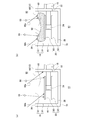
- FIGS. 3A and 3B are diagrams for explaining in principle a cryopump monitoring method according to an embodiment.
- FIG. 4 is a diagram illustrating a change in the operating frequency of the refrigerator during the evacuation operation of the cryopump.
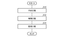
- 5 is a flowchart illustrating a cryopump monitoring method according to an embodiment. 6 is a flowchart showing the monitoring step shown in FIG. 5 in more detail.
- FIG. 1 is a diagram schematically illustrating a cryopump according to an embodiment.
- FIG. 4 is a diagram schematically illustrating an example of a condensed gas amount table according to an embodiment.
- FIG. 1 is a diagram schematically showing a cryopump 10 according to an embodiment.
- the cryopump 10 is attached to, for example, a vacuum chamber 90 of a sputtering apparatus, a vapor deposition apparatus, or another vacuum processing apparatus, and is used to increase the degree of vacuum inside the vacuum chamber 90 to a level required for a desired vacuum process. You.
- the cryopump 10 has a cryopump suction port (hereinafter, also referred to as a suction port) 12 for receiving a gas to be evacuated from the vacuum chamber. Gas enters the internal space 14 of the cryopump 10 through the intake port 12.
- the cryopump 10 may be intended to be installed and used in a vacuum chamber in the illustrated direction, that is, with the intake port 12 facing upward.
- the posture of the cryopump 10 is not limited thereto, and the cryopump 10 may be installed in the vacuum chamber in another direction.
- axial direction and “radial direction” may be used to clearly show the positional relationship of the components of the cryopump 10.
- the axial direction represents the direction passing through the intake port 12 (in FIG. 1, the direction along the cryopump central axis C passing through the center of the intake port 12), and the radial direction represents the direction along the intake port 12 (the direction perpendicular to the central axis C). ).
- a position relatively close to the intake port 12 in the axial direction may be referred to as “up” and a position relatively far from the intake port 12 may be referred to as “down”.
- a position relatively far from the bottom of the cryopump 10 may be referred to as “up”, and a position relatively close to the bottom may be referred to as “down”.
- a position close to the center of the intake port 12 (center axis C in FIG. 1) may be referred to as “inside”, and a position near the periphery of the intake port 12 may be referred to as “outside”.
- these expressions have nothing to do with the arrangement when the cryopump 10 is attached to the vacuum chamber.
- the cryopump 10 may be attached to the vacuum chamber with the intake port 12 facing downward in the vertical direction.
- a direction surrounding the axial direction may be referred to as a “circumferential direction”.
- the circumferential direction is a second direction along the intake port 12, and is a tangential direction orthogonal to the radial direction.
- the cryopump 10 includes a refrigerator 16, a first-stage cryopanel 18, a second-stage cryopanel 20, and a cryopump housing 70.
- the first-stage cryopanel 18 may be referred to as a high-temperature cryopanel portion or a 100K portion.
- the second-stage cryopanel 20 may be referred to as a low-temperature cryopanel portion or a 10K portion.
- the refrigerator 16 is a cryogenic refrigerator such as a Gifford McMahon refrigerator (so-called GM refrigerator).
- the refrigerator 16 is a two-stage refrigerator. Therefore, the refrigerator 16 includes a first cooling stage 22 and a second cooling stage 24.
- the refrigerator 16 is configured to cool the first cooling stage 22 to a first cooling temperature and cool the second cooling stage 24 to a second cooling temperature.
- the second cooling temperature is lower than the first cooling temperature.
- the first cooling stage 22 is cooled to about 65K to 120K, preferably 80K to 100K
- the second cooling stage 24 is cooled to about 10K to 20K.
- the refrigerator 16 further includes a refrigerator structure 21 that structurally supports the second cooling stage 24 on the first cooling stage 22 and structurally supports the first cooling stage 22 on the room temperature portion 26 of the refrigerator 16.
- the refrigerator structure 21 includes a first cylinder 23 and a second cylinder 25 that extend coaxially in the radial direction.
- the first cylinder 23 connects the room temperature part 26 of the refrigerator 16 to the first cooling stage 22.
- the second cylinder 25 connects the first cooling stage 22 to the second cooling stage 24.
- the room temperature section 26, the first cylinder 23, the first cooling stage 22, the second cylinder 25, and the second cooling stage 24 are linearly arranged in this order.
- a first displacer and a second displacer are reciprocally disposed inside the first cylinder 23 and the second cylinder 25, respectively.
- a first regenerator and a second regenerator are incorporated in the first displacer and the second displacer, respectively.
- the room temperature section 26 has a drive mechanism (not shown in FIG. 1, for example, a refrigerator motor 80) for reciprocating the first displacer and the second displacer.
- the drive mechanism includes a flow path switching mechanism that switches the flow path of the working gas so as to periodically supply and discharge the working gas (for example, helium) to the inside of the refrigerator 16.
- the first cooling stage 22 is installed at the first stage low temperature end of the refrigerator 16.
- the first cooling stage 22 is a member that encloses the end of the first cylinder 23 on the side opposite to the room temperature section 26 and surrounds the first expansion space of the working gas.
- the first expansion space is formed between the first cylinder 23 and the first displacer inside the first cylinder 23, and is a variable volume whose volume changes as the first displacer reciprocates.
- the first cooling stage 22 is formed of a metal material having a higher thermal conductivity than the first cylinder 23.
- the first cooling stage 22 is formed of copper
- the first cylinder 23 is formed of stainless steel.
- the second cooling stage 24 is installed at the low temperature end of the second stage of the refrigerator 16.
- the second cooling stage 24 is a member that encloses the end of the second cylinder 25 on the side opposite to the room temperature part 26 and surrounds the second expansion space of the working gas.
- the second expansion space is formed between the second cylinder 25 and the second displacer inside the second cylinder 25, and is a variable volume whose volume changes with reciprocation of the second displacer.
- the second cooling stage 24 is formed of a metal material having a higher thermal conductivity than the second cylinder 25.
- the second cooling stage 24 is formed of copper, and the second cylinder 25 is formed of stainless steel.
- the refrigerator 16 is connected to a compressor (not shown) for working gas.
- the refrigerator 16 cools the first cooling stage 22 and the second cooling stage 24 by expanding the working gas pressurized by the compressor therein.
- the expanded working gas is recovered by the compressor and pressurized again.
- the refrigerator 16 generates cold by repeating a thermodynamic cycle including supply and discharge of the working gas and reciprocation of the first displacer and the second displacer in synchronization with the supply and discharge of the working gas.
- the illustrated cryopump 10 is a so-called horizontal cryopump.
- the horizontal cryopump is generally a cryopump in which the refrigerator 16 is disposed so as to intersect (usually perpendicular to) the central axis C of the cryopump 10.
- the first cooling stage 22 and the second cooling stage 24 of the refrigerator 16 are arranged in a direction perpendicular to the central axis C of the cryopump (the horizontal direction in FIG. 1 and the direction of the central axis D of the refrigerator 16). .
- the first-stage cryopanel 18 includes a radiation shield 30 and an entrance cryopanel 32, and surrounds the second-stage cryopanel 20.
- the first-stage cryopanel 18 is a cryopanel provided to protect the second-stage cryopanel 20 from radiation heat from outside the cryopump 10 or from the cryopump housing 70.
- the first cryopanel 18 is thermally coupled to the first cooling stage 22. Therefore, the first stage cryopanel 18 is cooled to the first cooling temperature.
- the first cryopanel 18 has a gap between itself and the second cryopanel 20, and the first cryopanel 18 is not in contact with the second cryopanel 20.
- the radiation shield 30 and the entrance cryopanel 32 are formed of a metal material having a high thermal conductivity such as copper, for example, and may be covered with a plating layer such as nickel or another coating layer.
- the radiation shield 30 is provided to protect the second-stage cryopanel 20 from radiation heat of the cryopump housing 70.
- the radiation shield 30 is located between the cryopump housing 70 and the second cryopanel 20 and surrounds the second cryopanel 20.
- the radiation shield 30 has a shield main opening 34 for receiving gas from outside the cryopump 10 into the internal space 14.
- the shield main opening 34 is located at the intake port 12.
- the radiation shield 30 includes a shield front end 36 that defines the shield main opening 34, a shield bottom 38 located on the opposite side of the shield main opening 34, and a shield side 40 that connects the shield front end 36 to the shield bottom 38.
- the shield front end 36 forms a part of the shield side part 40.
- the shield side portion 40 extends in the axial direction from the shield front end 36 to the side opposite to the shield main opening 34, and extends in the circumferential direction so as to surround the second cooling stage 24.
- the radiation shield 30 has a cylindrical shape (for example, a cylindrical shape) in which the shield bottom 38 is closed, and is formed in a cup shape.
- An annular gap 42 is formed between the shield side portion 40 and the second cryopanel 20.
- the shield bottom 38 may be a separate member from the shield side 40.
- the shield bottom portion 38 may be a flat disk having substantially the same diameter as the shield side portion 40, and may be attached to the shield side portion 40 on the side opposite to the shield main opening 34. Further, at least a part of the shield bottom 38 may be open. For example, the radiation shield 30 may not be blocked by the shield bottom 38. That is, both ends of the shield side portion 40 may be open.
- the shield side portion 40 has a shield side opening 44 into which the refrigerator structure 21 is inserted.
- the second cooling stage 24 and the second cylinder 25 are inserted into the radiation shield 30 from outside the radiation shield 30 through the shield side opening 44.
- the shield side opening 44 is a mounting hole formed in the shield side portion 40 and is, for example, circular.
- the first cooling stage 22 is disposed outside the radiation shield 30.
- the shield side portion 40 includes a mounting seat 46 for the refrigerator 16.
- the mounting seat 46 is a flat portion for mounting the first cooling stage 22 to the radiation shield 30, and is slightly depressed when viewed from outside the radiation shield 30.
- the mounting seat 46 forms the outer periphery of the shield side opening 44.
- the mounting seat 46 is closer to the shield bottom 38 than the shield front end 36 in the axial direction.
- the radiation shield 30 is thermally coupled to the first cooling stage 22 by attaching the first cooling stage 22 to the mounting seat 46.
- the inlet cryopanel 32 is provided in the shield main opening 34 to protect the second cryopanel 20 from radiant heat from a heat source outside the cryopump 10.
- the heat source outside the cryopump 10 is, for example, a heat source inside the vacuum chamber 90 to which the cryopump 10 is attached.
- the entrance cryopanel 32 can restrict not only the radiant heat but also the entry of gas molecules.
- the inlet cryopanel 32 occupies a part of the opening area of the shield main opening 34 so as to limit the gas flow through the shield main opening 34 to a desired amount.
- An annular open area 48 is formed between the entrance cryopanel 32 and the shield front end 36.
- the entrance cryopanel 32 is attached to the shield front end 36 by an appropriate attachment member, and is thermally coupled to the radiation shield 30.
- the inlet cryopanel 32 is thermally coupled to the first cooling stage 22 via the radiation shield 30.
- the entrance cryopanel 32 has, for example, a plurality of annular or linear blades. Alternatively, the entrance cryopanel 32 may be a single plate-like member.
- the second cryopanel 20 is attached to the second cooling stage 24 so as to surround the second cooling stage 24. Therefore, the second cryopanel 20 is thermally coupled to the second cooling stage 24, and the second cryopanel 20 is cooled to the second cooling temperature.
- the second-stage cryopanel 20 is surrounded by the shield side portion 40 together with the second cooling stage 24.
- the second-stage cryopanel 20 includes a top cryopanel 60 facing the shield main opening 34, a cryopanel member 62 disposed between the top cryopanel 60 and the shield bottom 38, and a cryopanel mounting member 64.
- the cryopanel members 62 are arranged on both sides of the second cooling stage 24 with the cryopump center axis C interposed therebetween.
- the cryopanel member 62 is disposed along a plane perpendicular to the cryopump central axis C.
- the top cryopanel 60 and the cryopanel member 62 are mounted on the second cooling stage 24 via a cryopanel mounting member 64.
- the top cryopanel 60 is a part of the second cryopanel 20 that is closest to the entrance cryopanel 32.
- the top cryopanel 60 is disposed between the shield main opening 34 or the inlet cryopanel 32 and the refrigerator 16 in the axial direction.
- the top cryopanel 60 is located at the center of the internal space 14 of the cryopump 10 in the axial direction. Therefore, the space 65 for storing the condensed layer is formed widely between the front surface of the top cryopanel 60 and the entrance cryopanel 32.
- the condensed layer storage space 65 occupies the upper half of the internal space 14.
- the axial height of the housing space 65 may be in the range of 1/3 to 2/3 of the axial length of the radiation shield 30.
- the top cryopanel 60 is a generally flat cryopanel arranged perpendicular to the axial direction. That is, the top cryopanel 60 extends in the radial direction and the circumferential direction.
- the top cryopanel 60 is a disk-shaped panel having a size (for example, a projected area) larger than the entrance cryopanel 32.
- the relationship between the dimensions of the top cryopanel 60 and the entrance cryopanel 32 is not limited to this, and the top cryopanel 60 may be smaller or both may have substantially the same dimensions.
- the top cryopanel 60 is disposed so as to form a gap region 66 between the top cryopanel 60 and the refrigerator structure 21.
- the gap region 66 is a space formed in the axial direction between the back surface of the top cryopanel 60 and the second cylinder 25.
- the top cryopanel 60 and the cryopanel member 62 are formed of a metal material having a high thermal conductivity such as copper, for example, and may be covered with a plating layer such as nickel.
- the cryopanel member 62 is provided with an adsorbent 74 such as activated carbon.
- the adsorbent 74 is adhered to the back surface of the cryopanel member 62, for example.
- the front surface of the cryopanel member 62 is intended to function as a condensation surface, and the rear surface is intended to function as an adsorption surface.
- An adsorbent 74 may be provided on the front surface of the cryopanel member 62.
- the top cryopanel 60 may have the adsorbent 74 on the front and / or back. Alternatively, the top cryopanel 60 may not include the adsorbent 74.
- the cryopump 10 includes a gas flow adjusting member 50 configured to deflect the flow of gas flowing from the shield main opening 34 from the refrigerator structure 21.
- the gas flow adjusting member 50 is configured to deflect the gas flow flowing into the storage space 65 through the entrance cryopanel 32 or the open area 48 from the second cylinder 25.
- the gas flow adjusting member 50 may be a gas flow deflecting member or a gas flow reflecting member disposed above and adjacent to the refrigerator structure 21 or the second cylinder 25.
- the gas flow adjusting member 50 is locally provided at the same position as the shield side opening 44 in the circumferential direction.
- the gas flow adjusting member 50 has a rectangular shape when viewed from above.
- the gas flow adjusting member 50 is, for example, a single flat plate, but may be curved.
- the gas flow adjusting member 50 extends from the shield side portion 40 and is inserted into the gap region 66. However, the gas flow adjusting member 50 is not in contact with the top cryopanel 60, the second cylinder 25, and other portions of the second cooling temperature surrounding the gap region 66.
- the gas flow adjustment member 50 is thermally coupled to the first cooling stage 22 via the radiation shield 30. Therefore, the gas flow adjusting member 50 is cooled to the first cooling temperature.
- the cryopump housing 70 is a housing of the cryopump 10 that houses the first-stage cryopanel 18, the second-stage cryopanel 20, and the refrigerator 16, and is configured to maintain the vacuum tightness of the internal space 14. It is a vacuum container.
- the cryopump housing 70 includes the first-stage cryopanel 18 and the refrigerator structure 21 in a non-contact manner.
- the cryopump housing 70 is attached to the room temperature section 26 of the refrigerator 16.
- the inlet 12 is defined by the front end of the cryopump housing 70.
- the cryopump housing 70 has an inlet flange 72 extending radially outward from a front end thereof.
- the intake port flange 72 is provided over the entire circumference of the cryopump housing 70.
- the cryopump 10 is attached to the vacuum chamber 90 using the inlet flange 72.
- the cryopump housing 70 includes a cryopanel housing 76 surrounding the radiation shield 30 without contact with the radiation shield 30, and a refrigerator housing 77 surrounding the first cylinder 23 of the refrigerator 16.
- the cryopanel housing section 76 and the refrigerator housing section 77 are formed integrally.
- the cryopanel housing portion 76 has a cylindrical or dome shape in which an inlet flange 72 is formed at one end and the other end is closed as a housing bottom surface 70a.
- An opening through which the refrigerator 16 is inserted is formed separately from the intake port 12 on the side wall of the cryopanel housing portion 76 that connects the intake port flange 72 to the housing bottom surface 70a.
- the refrigerator housing portion 77 has a cylindrical shape extending from the opening to the room temperature portion 26 of the refrigerator 16. The refrigerator housing section 77 connects the cryopanel housing section 76 to the room temperature section 26 of the refrigerator 16.
- the cryopump 10 When the cryopump 10 is operated, first, the inside of the vacuum chamber 90 is roughly evacuated to about 1 Pa by another appropriate roughing pump before the operation. Thereafter, the cryopump 10 is operated. By driving the refrigerator 16, the first cooling stage 22 and the second cooling stage 24 are cooled to the first cooling temperature and the second cooling temperature, respectively. Therefore, the first-stage cryopanel 18 and the second-stage cryopanel 20 that are thermally coupled thereto are also cooled to the first cooling temperature and the second cooling temperature, respectively.
- the inlet cryopanel 32 cools gas flowing from the vacuum chamber 90 toward the cryopump 10.
- a gas having a sufficiently low vapor pressure for example, 10 ⁇ 8 Pa or less
- This gas may be referred to as a first type gas (also referred to as a type 1 gas).
- the first type gas is, for example, water vapor.
- the inlet cryopanel 32 can exhaust the first type gas. Part of the gas whose vapor pressure is not sufficiently low at the first cooling temperature passes through the inlet cryopanel 32 or the open area 48 and enters the accommodation space 65. Alternatively, another part of the gas is reflected by the entrance cryopanel 32 and does not enter the storage space 65.
- the gas that has entered the storage space 65 is cooled by the second-stage cryopanel 20.
- a gas having a sufficiently low vapor pressure for example, 10 ⁇ 8 Pa or less
- This gas may be referred to as a second type gas (also referred to as a type 2 gas).
- the second type gas is a gas that does not condense at the first cooling temperature.
- the second type gas is, for example, argon, nitrogen, or oxygen.
- the second stage cryopanel 20 can exhaust the second type gas. Since it directly faces the storage space 65, a condensed layer of the second type gas can grow largely on the front surface of the top cryopanel 60. Since the cryopump 10 has a large accommodation space 65, it can store a large amount of the second type gas.
- the gas whose vapor pressure is not sufficiently low at the second cooling temperature is adsorbed by the adsorbent 74 of the second-stage cryopanel 20.
- This gas may be referred to as a third type gas (also referred to as a type 3 gas).
- the third type gas is, for example, hydrogen.
- the second stage cryopanel 20 can exhaust the third type gas. Therefore, the cryopump 10 can exhaust various gases by condensing or adsorbing, and can reach a desired degree of vacuum in the vacuum chamber 90.
- the cryopump 10 is configured to have the storage space 65 for the condensed layer of the gas (for example, the second type gas).
- the first-stage cryopanel 18 is arranged so as to surround the storage space 65, and is cooled to a temperature higher than the condensation temperature of the second type gas.
- the second-stage cryopanel 20 is arranged so as to be surrounded by the inner surface of the first-stage cryopanel (for example, the inner surface of the shield side portion 40) together with the accommodation space 65, and is cooled to a temperature equal to or lower than the condensation temperature of the second type gas.
- On the second stage cryopanel 20 for example, the top cryopanel 60), a condensed layer of the second type gas is deposited.
- the intake port 12 enters a first-stage heat load (for example, radiant heat) incident on the inner surface of the first-stage cryopanel from outside the cryopump 10 (that is, the vacuum chamber 90), and enters the accommodation space 65 from outside the cryopump 10. Allow the passage of gas.
- a first-stage heat load for example, radiant heat
- the gate valve 92 is provided between the cryopump 10 and the vacuum chamber 90.
- the gate valve 92 is arranged adjacent to the intake port 12.
- An inlet flange 72 is attached to one side of the gate valve 92, and an opening of the vacuum chamber 90 is attached to the opposite side of the gate valve 92.
- the gate valve 92 When the gate valve 92 is open, the first-stage heat load and the second-class gas can enter the accommodation space 65 from the vacuum chamber 90 through the intake port 12.
- the intake port 12 is closed. Therefore, the first-stage heat load and the second-class gas do not enter the storage space 65.
- the gate valve 92 may be provided by a separate supplier from the cryopump 10 manufacturer, or may be provided with the cryopump 10 by the cryopump 10 manufacturer.
- a gate valve controller 94 for controlling the gate valve 92 may be provided.
- the gate valve controller 94 is configured to control opening and closing of the gate valve 92.
- the gate valve controller 94 may constitute a part of a control device of a vacuum processing device having the vacuum chamber 90.
- the gate valve controller 94 may be communicably connected to a cryopump controller (hereinafter, also referred to as a CP controller) 100 that controls the cryopump 10.
- the gate valve controller 94 may be configured to output a signal indicating the open / closed state of the gate valve 92 (for example, a gate valve closing signal G indicating that the gate valve 92 is closed) to the CP controller 100.
- the gate valve controller 94 may constitute a part of a cryopump controller (hereinafter, also referred to as a CP controller) 100 for controlling the cryopump 10 or may be provided alone.
- FIG. 2 is a control block diagram relating to the cryopump 10 shown in FIG.
- the control configuration of the cryopump 10 is realized by hardware and other elements and circuits including a CPU and a memory, and the software configuration is realized by a computer program and the like. It is depicted as a functional block realized by cooperation. It is understood by those skilled in the art that these functional blocks can be realized in various forms by a combination of hardware and software.
- the cryopump 10 includes the CP controller 100.
- the CP controller 100 includes a CPU that executes various arithmetic processes, a ROM that stores various control programs, a RAM that is used as a work area for storing data and executing programs, an input / output interface, and a memory. Further, the CP controller 100 is configured to be able to communicate with a higher-level controller (not shown) for controlling a vacuum process device to which the cryopump 10 is attached.
- the refrigerator 16 controls the refrigerator motor 80 as a drive source for driving the thermodynamic cycle of the refrigerator 16 and a specified voltage and frequency power supplied from an external power supply, for example, a commercial power supply. And a refrigerator inverter 82 for supplying.
- the refrigerator inverter 82 converts input power from an external power supply and outputs the converted power to the refrigerator motor 80 according to the operating frequency of the refrigerator 16 controlled by the CP controller 100.
- the refrigerator motor 80 is driven at the operating frequency determined by the CP controller 100 and output from the refrigerator inverter 82.
- the refrigerator motor 80 and the refrigerator inverter 82 may be mounted on the room temperature section 26 shown in FIG.
- the operating frequency (also referred to as an operating speed) of the refrigerator 16 includes an operating frequency or a rotation speed of the refrigerator motor 80, an operating frequency of the refrigerator inverter 82, a thermodynamic cycle of the refrigerator 16 (for example, a refrigeration cycle such as a GM cycle). ) Or any of these.
- the frequency of the thermodynamic cycle is the number of thermodynamic cycles performed in the refrigerator 16 per unit time.
- the refrigerator 16 includes a cryopanel temperature sensor 84.
- the cryopanel temperature sensor 84 is mounted on the first cooling stage 22 and measures the temperature of the first cryopanel 18.
- the cryopanel temperature sensor 84 may be mounted on the first cryopanel 18.
- the cryopanel temperature sensor 84 is communicably connected to the CP controller 100 so as to periodically measure the temperature of the first-stage cryopanel 18 and output a signal indicating the measured temperature value to the CP controller 100.
- the CP controller 100 includes a first-stage temperature control unit 102 that controls the operating frequency of the refrigerator 16 to cool the first-stage cryopanel 18 to the first-stage target temperature.
- the first-stage temperature control unit 102 is configured to determine the operating frequency of the refrigerator 16 as a function of the deviation between the first-stage target temperature and the measured temperature of the first-stage cryopanel 18 (for example, by PID control). .
- the temperature of the first cryopanel 18 may increase.
- the first-stage temperature controller 102 increases the operating frequency of the refrigerator 16.
- the frequency of the thermodynamic cycle in the refrigerator 16 is also increased (that is, the refrigerating capacity of the refrigerator 16 is increased), and the first-stage cryopanel 18 is cooled toward the first-stage target temperature.
- the temperature measured by the cryopanel temperature sensor 84 is lower than the target temperature, the operating frequency of the refrigerator 16 is reduced and the refrigerating capacity is reduced, and the first-stage cryopanel 18 reaches the first-stage target temperature. The temperature is raised toward.
- the temperature of the first-stage cryopanel 18 can be kept in a temperature range near the first-stage target temperature. Since the operating frequency of the refrigerator 16 can be appropriately adjusted according to the first-stage heat load, such control helps reduce the power consumption of the cryopump 10.
- the CP controller 100 also includes a second-stage cryopanel monitoring unit 104 that monitors the amount of condensed gas in the storage space 65 based on a change in the first-stage heat load.
- the second-stage cryopanel monitoring unit 104 may be configured to receive a signal indicating the open / closed state of the gate valve 92 (for example, a gate valve closing signal G) from the gate valve controller 94. The details of the second-stage cryopanel monitoring unit 104 will be described later.
- FIGS. 3A and 3B are diagrams for explaining in principle the method of monitoring the cryopump 10 according to an embodiment.
- FIG. 3A shows an initial situation in which there is no second-class gas condensed layer
- FIG. 3B shows that the second-class gas condensed layer 68 has a top cryopanel during the evacuation operation of the cryopump 10.
- 60 shows the situation where it has grown.
- the condensed layer 68 is a gas such as a second type gas such as ice or frost.
- the radiant heat 86 a and 86 b and the gas molecules 88 of the second type gas enter the accommodation space 65 from outside the cryopump 10 through the open area 48 of the intake port 12.
- the radiant heats 86 a and 86 b and the gas molecules 88 of the second type gas enter the cryopump 10 from the vacuum chamber 90 along a straight path.
- the entry angle may depend on the design of the vacuum chamber 90, including the location of the heat source and gas inlet within the vacuum chamber 90.
- an exemplary incident path of the radiant heat 86a, 86b is illustrated by a solid arrow
- an exemplary incident path of the second type gas molecule 88 is illustrated by a broken arrow.
- a part of the radiant heat 86a enters the inner surface of the first-stage cryopanel, for example, the inner surface of the radiation shield 30, and becomes the first-stage heat load.
- the radiant heat 86a is incident on the inner peripheral surface of the shield side portion 40, but depending on the incident angle of the radiant heat 86a, the radiant heat 86a is also transmitted to the inner peripheral surface of the shield front end 36 or the upper surface of the shield bottom portion 38. Can be incident.
- Another part of the radiant heat 86b is incident on the upper surface of the second cryopanel 20, for example, the top cryopanel 60, and becomes a second heat load.
- the first stage heat load is removed by the first cooling stage 22 of the refrigerator 16 and the second stage heat load is removed by the second cooling stage 24 of the refrigerator 16.
- the gas molecules 88 of the second-class gas are topped as a second-class gas condensed layer 68 as shown in FIG. It is deposited on the cryopanel 60.
- the condensation layer 68 can also be deposited on the cryopanel member 62, but is not shown here.
- An inlet cryopanel 32 is disposed at the center of the inlet 12 and an open area 48 is formed around the inlet cryopanel 32, so that the growth rate of the condensed layer 68 and the resulting thickness of the condensed layer 68 (axial height) ) Is larger at the outer edge and smaller at the center. Therefore, the condensed layer 68 swells below the open area 48 and has a shape having a recess below the entrance cryopanel 32, as shown in the figure.
- condensed layer 68 eventually contacts any portion of first stage cryopanel 18 (eg, shield front end 36, shield side 40, and / or entrance cryopanel 32). .
- the cooling temperature of the first-stage cryopanel 18 is higher than the condensation temperature of the second-class gas, and the first-stage cryopanel 18 cannot condense the second-class gas. Re-vaporized at the contact site.
- the second type gas stored in the cryopump 10 as the condensed layer 68 is re-discharged, and thereafter, the cryopump 10 cannot provide an exhaust function of the second type gas. That is, the cryopump 10 reaches the storage limit at the time of contact between the first-stage cryopanel 18 and the condensing layer 68.
- cryopump housing 70 is provided with a viewport or other viewing window, the operator can reach the storage limit soon by viewing the condensed layer 68 from the outside of the cryopump 10 through the viewing window. Or not.
- existing cryopumps 10 do not have such viewing windows.
- the condensed layer 68 cannot be visually observed.
- the storage limit depends on the specific shape of the condensed layer 68 because of the physical contact between the first-stage cryopanel 18 and the condensed layer 68. Therefore, it is difficult to accurately predict the arrival time of the storage limit from only the cumulative amount of the second type gas introduced into the vacuum chamber 90.
- this document proposes a new technique for predicting in real time that the amount of the second type gas stored in the cryopump 10 is approaching the storage limit during the evacuation operation of the cryopump 10.
- the amount of condensed gas in the storage space 65 is monitored based on the change in the first-stage heat load.
- This concept is based on the fact that the ratio of the first-stage heat load and the second-stage heat load incident on the cryopump 10 through the intake port 12 changes according to the volume and / or shape of the condensed layer 68.
- the volume and / or shape of the condensed layer 68 changes, the first-stage heat load and the second-stage heat load respectively change, and the cooling balance of the first-stage cryopanel 18 and the second-stage cryopanel 20 by the refrigerator 16 is increased. change. Therefore, by detecting a change in the first-stage heat load, information indicating a change in the volume and / or shape of the condensation layer 68 can be obtained.
- the first stage heat load tends to decrease and the second stage heat load tends to increase. It can be said that the amount of the second type gas stored in the condensing layer 68 is correlated with the first stage heat load (or the second stage heat load).
- the first-stage heat load decreases, it can be determined that the amount of condensed gas in the storage space 65 has increased.
- the first-stage heat load increases (in general, the amount of condensed gas gradually increases during the evacuation operation of the cryopump 10, such a situation hardly occurs), It can be determined that the gas amount has decreased. In this manner, the amount of condensed gas in the storage space 65 can be monitored based on the change in the first-stage heat load.
- a change in the first-stage heat load can be detected as a change in at least one operating parameter of the refrigerator 16.
- the change in the first-stage heat load is caused by the change in the operating frequency of the refrigerator 16. Can be detected.
- FIG. 4 shows a change in the operating frequency of the refrigerator 16 during the evacuation operation of the cryopump 10.
- the vertical axis represents the operating frequency [Hz] of the refrigerator 16 and the horizontal axis represents the amount [std @ L] of the second type gas (argon gas) supplied to the vacuum chamber 90, which is shown in FIG. This corresponds to the amount (also referred to as occlusion amount) of the second type gas condensed in the condensing layer 68 shown in b).
- the operating frequency of the refrigerator 16 tends to decrease as the storage amount increases. As the amount of occlusion increases and the condensed layer 68 grows, the first-stage heat load decreases as described above. If the first-stage heat load decreases, the temperature of the first-stage cryopanel 18 measured by the cryopanel temperature sensor 84 may decrease. However, since the temperature of the first-stage cryopanel 18 is controlled to the first-stage target temperature, the operating frequency of the refrigerator 16 is actually reduced, the refrigeration capacity of the refrigerator 16 is reduced, and the first-stage cryopanel is reduced. The panel 18 is maintained at the first-stage target temperature. It is to be noted that although shown is a test result by the present inventor of the cryopump 10 having a certain specific design, it has been confirmed that the same tendency is applied to various cryopumps 10.
- the vertical axis of FIG. 4 shows the first threshold value S1 and the second threshold value S2, and the horizontal axis shows the designed storage limit value VL.
- the first threshold value S1 corresponds to an operation frequency of the refrigerator 16 that can be obtained when the amount of second gas stored by the cryopump 10 reaches a designed storage limit value VL.
- the second threshold value S2 corresponds to an operating frequency of the refrigerator 16 that can be obtained when the storage amount of the second type gas by the cryopump 10 reaches the allowable storage amount VA.
- the allowable storage amount VA is a value obtained by subtracting a predetermined margin from a design storage limit value VL.
- the margin may be as large as, for example, within 20%, or within 10%, or within 5% of the designed storage limit value VL, and may be larger than, for example, 1% of the designed storage limit value VL. Is also good.
- the first threshold value S1 and the second threshold value S2 can be appropriately determined experimentally or empirically.
- the operating frequency of the refrigerator 16 decreases to the first threshold value S1 or the second threshold value S2 during the evacuation operation of the cryopump 10, the amount of second-class gas stored approaches the storage limit. Can be considered to be.
- the operating frequency of the refrigerator 16 can be used as an index indicating the amount of second gas stored, that is, the amount of condensed gas in the storage space 65 in real time. As described above, by monitoring the operating frequency of the refrigerator 16, it is possible to predict in real time that the storage amount of the second type gas is approaching the storage limit during the evacuation operation of the cryopump 10.
- FIG. 5 is a flowchart showing a method for monitoring the cryopump 10 according to an embodiment. This method includes a cooling step (S10), a deposition step (S12), and a monitoring step (S14).
- the cooling step (S10) includes controlling the operating frequency of the refrigerator 16 by the first-stage temperature controller 102 of the CP controller 100 to cool the first-stage cryopanel 18 to the first-stage target temperature. .
- the second-stage gas condensed layer 68 that enters the storage space 65 from outside the cryopump 10 through the intake port 12 is formed on the second-stage cryopanel 20. Including depositing.
- the monitoring step (S14) is to monitor the amount of condensed gas in the storage space 65 based on a change in the first-stage heat load incident on the inner surface of the first-stage cryopanel 18 from the outside of the cryopump 10 through the air inlet 12. including.
- the amount of the condensed gas in the storage space 65 mainly corresponds to the amount of the second type gas captured by the condensed layer 68 condensed on the top cryopanel 60.
- the amount of condensed gas is reduced by the second-stage cryopanel monitoring unit 104 of the CP controller 100 when the first-stage heat load decreases (for example, when the operating frequency of the refrigerator 16 decreases). Including determining that the number has increased. Further, the second-stage cryopanel monitoring unit 104 may determine that the condensed gas amount has decreased when the first-stage heat load increases (for example, when the operating frequency of the refrigerator 16 increases).
- FIG. 6 is a flowchart showing the monitoring step (S14) shown in FIG. 5 in more detail.
- the second-stage cryopanel monitoring unit 104 acquires the operating frequency of the refrigerator 16 from the first-stage temperature control unit 102 (S16).
- the operating frequency of the refrigerator 16 can be changed according to a change in the amount of heat input from the vacuum chamber 90 to the cryopump 10 through the air inlet 12.
- the amount of heat input from the vacuum chamber 90 can depend, for example, on the vacuum process performed in the vacuum chamber 90.
- Such a change in the thermal conditions in the vacuum chamber 90 may cause an error in estimating the amount of condensed gas based on the operating frequency of the refrigerator 16. Therefore, it is preferable that the second-stage cryopanel monitoring unit 104 obtains the operating frequency of the refrigerator 16 at a timing at which radiant heat entering the intake port 12 from outside the cryopump 10 becomes a predetermined value. This can reduce or prevent the influence of the change in the thermal conditions in the vacuum chamber 90.
- the timing is set, for example, while the gate valve 92 is closed. Therefore, the second-stage cryopanel monitoring unit 104 may acquire the operating frequency of the refrigerator 16 in response to the gate valve closing signal G.
- the closing of the gate valve 92 closes the intake port 12 and isolates the internal space 14 of the cryopump 10 from the vacuum chamber 90. Therefore, heat input from the vacuum chamber 90 to the cryopump 10 through the air inlet 12 is limited or substantially shut off.
- the second-stage cryopanel monitoring unit 104 can reduce the influence of a change in thermal conditions in the vacuum chamber 90 or prevent the refrigerator from being affected. Sixteen operating frequencies can be obtained.
- the second-stage cryopanel monitoring unit 104 may acquire the operating frequency or other operating parameters of the refrigerator 16 from the first-stage temperature control unit 102 when the operation state of the refrigerator 16 is stabilized.
- the second-stage cryopanel monitoring unit 104 may acquire the operating frequency of the refrigerator 16 when a predetermined time has elapsed from the reception of the gate valve closing signal G or other timing.
- the second-stage cryopanel monitoring unit 104 may acquire the operating frequency of the refrigerator 16 when the change rate of the operating frequency of the refrigerator 16 becomes within a predetermined threshold after the above timing. By doing so, it is possible to avoid acquiring the operating frequency of the refrigerator 16 in a transient state such as immediately after the gate valve 92 is closed.
- the second-stage cryopanel monitoring unit 104 compares the obtained operating frequency of the refrigerator 16 with the threshold value S (S18).
- the threshold value S may be either the first threshold value S1 or the second threshold value S2 shown in FIG.
- the second-stage cryopanel monitoring unit 104 determines that the condensed gas amount has exceeded the reference value (S20).
- the threshold value S is the first threshold value S1
- the reference value corresponds to a design storage limit value VL.
- the threshold value S is the second threshold value S2
- the reference value corresponds to the allowable storage amount VA.
- the second-stage cryopanel monitoring unit 104 may be configured to output that the condensed gas amount has exceeded a reference value.
- the second-stage cryopanel monitoring unit 104 may be configured to indicate to the operator that the amount of condensed gas has exceeded the reference value in the form of an image, a sound, or any other appropriate format.
- the second-stage cryopanel monitoring unit 104 determines that the condensed gas amount is lower than the reference value (S22). Similarly, the second-stage cryopanel monitoring unit 104 may be configured to output that the condensed gas amount is lower than the reference value.
- the monitoring step (S14) ends.
- the monitoring step (S14) may be repeated each time it is allowed to close the gate valve 92, periodically, or at any other appropriate frequency.
- FIG. 7 is a diagram schematically showing a cryopump 10 according to an embodiment.
- the refrigerator 16 may include a variable output heater 96 for heating the first cooling stage 22, for example, an electric heater.
- the heater 96 may be mounted on the first cooling stage 22. Alternatively, the heater 96 may be attached to any part of the first-stage cryopanel 18.
- the first-stage temperature control unit 102 controls the output of the heater 96 (for example, the voltage and / or current supplied to the heater 96) to cool the first-stage cryopanel 18 to the first-stage target temperature. You may.
- the first-stage temperature control unit 102 may be configured to determine the output of the heater 96 as a function of the deviation between the first-stage target temperature and the measured temperature of the first-stage cryopanel 18 (for example, by PID control). .
- the temperature of the first cryopanel 18 may increase.
- the first-stage temperature control unit 102 reduces the output of the heater 96.
- the first stage cryopanel 18 is cooled toward the first stage target temperature.
- the first-stage temperature control unit 102 increases the output of the heater 96.
- the first stage cryopanel 18 is heated toward the first stage target temperature.
- the temperature of the first-stage cryopanel 18 can be kept in a temperature range near the first-stage target temperature.
- the second-stage cryopanel monitoring unit 104 monitors the amount of condensed gas in the storage space 65 based on a change in the first-stage heat load, and more specifically, when the first-stage heat load decreases, the storage space is reduced. It is determined that the amount of condensed gas in 65 has increased. Therefore, the second-stage cryopanel monitoring unit 104 may be configured to acquire the output of the heater 96 from the first-stage temperature control unit 102 and compare the output of the heater 96 with a threshold. The second-stage cryopanel monitoring unit 104 may determine that the condensed gas amount has exceeded the reference value when the output of the heater 96 exceeds the threshold. The second-stage cryopanel monitoring unit 104 may determine that the amount of condensed gas falls below the reference value when the output of the heater 96 is less than the threshold.
- the second-stage cryopanel monitoring unit 104 may obtain the output of the heater 96 from the first-stage temperature control unit 102 at the timing when the radiant heat entering the intake port 12 from outside the cryopump 10 becomes a predetermined value.
- the timing may be set while the gate valve 92 is closed.
- the amount of condensed gas in the storage space 65 is monitored based on the change in the first-stage heat load. Since the change in the first-stage heat load reflects the change in the shape of the condensed layer 68, compared to the existing attempts to predict the reaching of the storage limit from only the accumulated amount of the second type gas introduced into the vacuum chamber 90. Thus, the amount of condensed gas in the cryopump 10 can be more accurately estimated. It can be predicted during use of the cryopump that the amount of gas stored in the cryopump 10 is approaching the storage limit.
- a change in the first-stage heat load is detected as a change in the operation parameter of the refrigerator 16 such as the operation frequency or the heater output of the refrigerator 16, and the inside of the accommodation space 65 is determined based on the detected change in the operation parameter. Is monitored. In this way, it can be predicted in real time during the evacuation operation of the cryopump 10 that the storage amount of the second type gas is approaching the storage limit.
- the second-stage cryopanel monitoring unit 104 determines a plurality of values of the condensed gas amount by operating parameters of the refrigerator 16 (for example, operating frequency or output of the heater 96). ) May be provided.
- the condensed gas amount table 106 may have a look-up table, a function, or any other form.
- the second-stage cryopanel monitoring unit 104 may acquire the operation parameters of the refrigerator 16 from the first-stage temperature control unit 102.
- the second-stage cryopanel monitoring unit 104 may calculate an estimated value of the condensed gas amount from the operation parameters of the refrigerator 16 and the condensed gas amount table 106.
- the second-stage cryopanel monitoring unit 104 may be configured to output the estimated value of the calculated condensed gas amount in the form of an image, a sound, or another appropriate format. By doing so, the cryopump 10 can estimate the amount of condensed gas in real time.
- the vertical cryopump refers to a cryopump in which the refrigerator 16 is disposed along the cryopump center axis C of the cryopump 10.
- the internal configuration of the cryopump such as the arrangement, shape, and number of cryopanels, is not limited to the specific embodiment described above. Various known configurations can be appropriately adopted.
- the present invention can be used in the field of a cryopump and a method for monitoring a cryopump.
Landscapes
- Engineering & Computer Science (AREA)
- Mechanical Engineering (AREA)
- General Engineering & Computer Science (AREA)
- Computer Hardware Design (AREA)
- Compressors, Vaccum Pumps And Other Relevant Systems (AREA)
Abstract
Description
Claims (12)
- 気体の凝縮層の収容スペースを有するクライオポンプであって、
前記気体の凝縮温度より高い温度に冷却される第1段クライオパネルであって、前記収容スペースを囲むように配置された第1段クライオパネル内面を有する第1段クライオパネルと、
前記気体の凝縮温度以下の温度に冷却され、前記気体の凝縮層が堆積する第2段クライオパネルであって、前記収容スペースとともに前記第1段クライオパネル内面に囲まれて配置された第2段クライオパネルと、
前記クライオポンプの外から前記第1段クライオパネル内面に入射する第1段熱負荷、および、前記クライオポンプの外から前記収容スペースに進入する前記気体の通過を許容するクライオポンプ吸気口と、
前記第1段熱負荷の変化に基づいて前記収容スペース内の凝縮気体量を監視する第2段クライオパネル監視部と、を備えることを特徴とするクライオポンプ。 - 前記第2段クライオパネル監視部は、前記第1段熱負荷が減少した場合に前記凝縮気体量が増加したと判定することを特徴とする請求項1に記載のクライオポンプ。
- 前記第1段クライオパネルに熱的に結合された第1冷却ステージと、前記第2段クライオパネルに熱的に結合された第2冷却ステージとを備える冷凍機と、
前記第1段クライオパネルを第1段目標温度に冷却すべく前記冷凍機の運転周波数を制御する第1段温度制御部と、をさらに備え、
前記第2段クライオパネル監視部は、前記冷凍機の運転周波数をしきい値と比較し、前記冷凍機の運転周波数が前記しきい値を下回る場合に前記凝縮気体量が基準値を超えたと判定することを特徴とする請求項1または2に記載のクライオポンプ。 - 前記第2段クライオパネル監視部は、前記クライオポンプ吸気口に前記クライオポンプの外から入射する輻射熱が既定値となるタイミングで前記冷凍機の運転周波数を取得し、取得した前記冷凍機の運転周波数を前記しきい値と比較することを特徴とする請求項3に記載のクライオポンプ。
- 前記クライオポンプ吸気口を閉鎖するゲートバルブが設けられており、
前記タイミングは、前記ゲートバルブの閉鎖中に設定されることを特徴とする請求項4に記載のクライオポンプ。 - 前記凝縮気体量の複数の値それぞれを前記冷凍機の運転周波数の値に対応付けた凝縮気体量テーブルをさらに備え、
前記第2段クライオパネル監視部は、前記冷凍機の運転周波数と前記凝縮気体量テーブルから前記凝縮気体量の推測値を算出することを特徴とする請求項3から5のいずれかに記載のクライオポンプ。 - 前記第1段クライオパネルに熱的に結合された第1冷却ステージと、前記第1冷却ステージを加熱するヒータと、前記第2段クライオパネルに熱的に結合された第2冷却ステージとを備える冷凍機と、
前記第1段クライオパネルを第1段目標温度に冷却すべく前記ヒータの出力を制御する第1段温度制御部と、をさらに備え、
前記第2段クライオパネル監視部は、前記ヒータの出力をしきい値と比較し、前記ヒータの出力が前記しきい値を上回る場合に前記凝縮気体量が基準値を超えたと判定することを特徴とする請求項1または2に記載のクライオポンプ。 - 前記第1段クライオパネルに熱的に結合された第1冷却ステージと、前記第2段クライオパネルに熱的に結合された第2冷却ステージとを備える冷凍機と、
前記第1段クライオパネルを第1段目標温度に冷却すべく前記冷凍機の運転パラメータを制御する第1段温度制御部と、をさらに備え、
前記第2段クライオパネル監視部は、前記冷凍機の運転パラメータを前記第1段温度制御部から取得し、前記冷凍機の運転パラメータをしきい値と比較することにより前記凝縮気体量が基準値を超えたか否かを判定することを特徴とする請求項1または2に記載のクライオポンプ。 - 前記第2段クライオパネル監視部は、前記クライオポンプ吸気口に前記クライオポンプの外から入射する輻射熱が既定値となるタイミングで前記冷凍機の運転パラメータを取得し、取得した前記冷凍機の運転パラメータを前記しきい値と比較することを特徴とする請求項8に記載のクライオポンプ。
- 前記凝縮気体量の複数の値それぞれを前記冷凍機の運転パラメータの値に対応付けた凝縮気体量テーブルをさらに備え、
前記第2段クライオパネル監視部は、前記冷凍機の運転パラメータと前記凝縮気体量テーブルから前記凝縮気体量の推測値を算出することを特徴とする請求項8または9に記載のクライオポンプ。 - 前記第1段クライオパネルは第1冷却温度に冷却され、前記第2段クライオパネルは前記第1冷却温度より低い第2冷却温度に冷却され、
前記気体は、前記第1冷却温度では凝縮せず、前記第2冷却温度で凝縮するタイプ2ガスであることを特徴とする請求項1から10のいずれかに記載のクライオポンプ。 - クライオポンプの監視方法であって、
前記クライオポンプは、気体の凝縮層の収容スペースを囲むように配置された第1段クライオパネル内面を有する第1段クライオパネルと、前記収容スペースとともに前記第1段クライオパネル内面に囲まれて配置された第2段クライオパネルと、を備え、
前記方法は、
前記第1段クライオパネルを前記気体の凝縮温度より高い温度に冷却するとともに、前記第2段クライオパネルを前記気体の凝縮温度以下の温度に冷却することと、
前記クライオポンプの外からクライオポンプ吸気口を通じて前記収容スペースに進入する前記気体の凝縮層を前記第2段クライオパネルに堆積させることと、
前記クライオポンプの外から前記クライオポンプ吸気口を通じて前記第1段クライオパネル内面に入射する第1段熱負荷の変化に基づいて前記収容スペース内の凝縮気体量を監視することと、を備えることを特徴とする方法。
Priority Applications (4)
| Application Number | Priority Date | Filing Date | Title |
|---|---|---|---|
| CN201980055056.8A CN112639288B (zh) | 2018-09-03 | 2019-08-01 | 低温泵及低温泵的监视方法 |
| JP2020541068A JP7369129B2 (ja) | 2018-09-03 | 2019-08-01 | クライオポンプおよびクライオポンプの監視方法 |
| KR1020217005152A KR102597865B1 (ko) | 2018-09-03 | 2019-08-01 | 크라이오펌프 및 크라이오펌프의 감시방법 |
| US17/188,408 US11920576B2 (en) | 2018-09-03 | 2021-03-01 | Cryopump and method of monitoring cryopump |
Applications Claiming Priority (2)
| Application Number | Priority Date | Filing Date | Title |
|---|---|---|---|
| JP2018164405 | 2018-09-03 | ||
| JP2018-164405 | 2018-09-03 |
Related Child Applications (1)
| Application Number | Title | Priority Date | Filing Date |
|---|---|---|---|
| US17/188,408 Continuation US11920576B2 (en) | 2018-09-03 | 2021-03-01 | Cryopump and method of monitoring cryopump |
Publications (1)
| Publication Number | Publication Date |
|---|---|
| WO2020049915A1 true WO2020049915A1 (ja) | 2020-03-12 |
Family
ID=69722505
Family Applications (1)
| Application Number | Title | Priority Date | Filing Date |
|---|---|---|---|
| PCT/JP2019/030301 Ceased WO2020049915A1 (ja) | 2018-09-03 | 2019-08-01 | クライオポンプおよびクライオポンプの監視方法 |
Country Status (6)
| Country | Link |
|---|---|
| US (1) | US11920576B2 (ja) |
| JP (1) | JP7369129B2 (ja) |
| KR (1) | KR102597865B1 (ja) |
| CN (1) | CN112639288B (ja) |
| TW (1) | TWI710699B (ja) |
| WO (1) | WO2020049915A1 (ja) |
Cited By (2)
| Publication number | Priority date | Publication date | Assignee | Title |
|---|---|---|---|---|
| GB2588826A (en) * | 2019-11-11 | 2021-05-12 | Edwards Vacuum Llc | Cryopump |
| US20260028975A1 (en) * | 2024-07-29 | 2026-01-29 | Applied Materials, Inc. | Protective coatings for cryogenic pump components in process chambers |
Families Citing this family (1)
| Publication number | Priority date | Publication date | Assignee | Title |
|---|---|---|---|---|
| JP7856447B2 (ja) * | 2022-02-18 | 2026-05-11 | 住友重機械工業株式会社 | クライオポンプおよびクライオポンプの運転方法 |
Citations (4)
| Publication number | Priority date | Publication date | Assignee | Title |
|---|---|---|---|---|
| JPS60256574A (ja) * | 1984-06-01 | 1985-12-18 | Hitachi Ltd | クライオポンプ |
| JPS6480777A (en) * | 1987-09-24 | 1989-03-27 | Hitachi Ltd | Cryopump |
| JPH07293438A (ja) * | 1994-04-28 | 1995-11-07 | Ebara Corp | クライオポンプ |
| JPH11214199A (ja) * | 1998-01-21 | 1999-08-06 | Mitsubishi Electric Corp | サイクロトロン装置の真空排気装置、真空排気方法および真空ポンプの再生方法 |
Family Cites Families (19)
| Publication number | Priority date | Publication date | Assignee | Title |
|---|---|---|---|---|
| JPH0861232A (ja) * | 1994-08-24 | 1996-03-08 | Ebara Corp | クライオポンプの再生方法及び再生装置 |
| DE69528913T2 (de) | 1994-04-28 | 2003-09-04 | Ebara Corp., Tokio/Tokyo | Kryopumpe |
| US7555911B2 (en) * | 2002-08-20 | 2009-07-07 | Sumitomo Heavy Industries, Ltd. | Cryogenic refrigerator |
| TWI490408B (zh) * | 2008-04-04 | 2015-07-01 | Brooks Automation Inc | 利用錫鎵合金的低溫泵 |
| JP4686572B2 (ja) * | 2008-05-14 | 2011-05-25 | 住友重機械工業株式会社 | クライオポンプ、真空排気システム、及びその診断方法 |
| JP4521047B2 (ja) * | 2008-05-16 | 2010-08-11 | 住友重機械工業株式会社 | クライオポンプ |
| WO2010038415A1 (ja) * | 2008-09-30 | 2010-04-08 | キヤノンアネルバ株式会社 | 真空排気システム、真空排気システムの運転方法、冷凍機、真空排気ポンプ、冷凍機の運転方法、二段式冷凍機の運転制御方法、クライオポンプの運転制御方法、二段式冷凍機、クライオポンプ、基板処理装置、電子デバイスの製造方法 |
| WO2010097888A1 (ja) * | 2009-02-24 | 2010-09-02 | キヤノンアネルバテクニクス株式会社 | 二段式冷凍機の運転制御方法、二段式冷凍機を有するクライオポンプの運転制御方法、二段式冷凍機、クライオポンプ及び真空基板処理装置 |
| JP5084794B2 (ja) * | 2009-07-22 | 2012-11-28 | 住友重機械工業株式会社 | クライオポンプ、及びクライオポンプの監視方法 |
| JP5634323B2 (ja) * | 2011-05-13 | 2014-12-03 | 住友重機械工業株式会社 | クライオポンプシステム、クライオポンプのための再生方法 |
| JP5846966B2 (ja) * | 2012-03-01 | 2016-01-20 | 住友重機械工業株式会社 | クライオポンプ及びその再生方法 |
| JP6076843B2 (ja) | 2013-06-14 | 2017-02-08 | 住友重機械工業株式会社 | クライオポンプ |
| JP6084119B2 (ja) * | 2013-05-27 | 2017-02-22 | 住友重機械工業株式会社 | クライオポンプ |
| TWI601923B (zh) * | 2013-08-19 | 2017-10-11 | 住友重機械工業股份有限公司 | Monitoring methods and cooling system |
| KR20150114225A (ko) * | 2014-04-01 | 2015-10-12 | 주식회사 조인솔루션 | 스토리지 탱크를 이용한 가변용량형 크라이오 압축기장치 |
| US10060655B2 (en) * | 2014-08-11 | 2018-08-28 | Raytheon Company | Temperature control of multi-stage cryocooler with load shifting capabilities |
| JP6415230B2 (ja) * | 2014-10-07 | 2018-10-31 | 住友重機械工業株式会社 | クライオポンプ |
| JP6410590B2 (ja) * | 2014-12-17 | 2018-10-24 | 住友重機械工業株式会社 | コールドトラップ及びコールドトラップの制御方法 |
| JP6615663B2 (ja) * | 2016-03-22 | 2019-12-04 | 住友重機械工業株式会社 | クライオポンプ、クライオポンプ吸蔵ガス量推測装置及びクライオポンプ吸蔵ガス量推測方法 |
-
2019
- 2019-08-01 WO PCT/JP2019/030301 patent/WO2020049915A1/ja not_active Ceased
- 2019-08-01 CN CN201980055056.8A patent/CN112639288B/zh active Active
- 2019-08-01 JP JP2020541068A patent/JP7369129B2/ja active Active
- 2019-08-01 KR KR1020217005152A patent/KR102597865B1/ko active Active
- 2019-08-30 TW TW108131174A patent/TWI710699B/zh active
-
2021
- 2021-03-01 US US17/188,408 patent/US11920576B2/en active Active
Patent Citations (4)
| Publication number | Priority date | Publication date | Assignee | Title |
|---|---|---|---|---|
| JPS60256574A (ja) * | 1984-06-01 | 1985-12-18 | Hitachi Ltd | クライオポンプ |
| JPS6480777A (en) * | 1987-09-24 | 1989-03-27 | Hitachi Ltd | Cryopump |
| JPH07293438A (ja) * | 1994-04-28 | 1995-11-07 | Ebara Corp | クライオポンプ |
| JPH11214199A (ja) * | 1998-01-21 | 1999-08-06 | Mitsubishi Electric Corp | サイクロトロン装置の真空排気装置、真空排気方法および真空ポンプの再生方法 |
Cited By (3)
| Publication number | Priority date | Publication date | Assignee | Title |
|---|---|---|---|---|
| GB2588826A (en) * | 2019-11-11 | 2021-05-12 | Edwards Vacuum Llc | Cryopump |
| US12146480B2 (en) | 2019-11-11 | 2024-11-19 | Edwards Vacuum Llc | Cryopump |
| US20260028975A1 (en) * | 2024-07-29 | 2026-01-29 | Applied Materials, Inc. | Protective coatings for cryogenic pump components in process chambers |
Also Published As
| Publication number | Publication date |
|---|---|
| JPWO2020049915A1 (ja) | 2021-08-12 |
| TWI710699B (zh) | 2020-11-21 |
| TW202010939A (zh) | 2020-03-16 |
| JP7369129B2 (ja) | 2023-10-25 |
| KR102597865B1 (ko) | 2023-11-02 |
| US11920576B2 (en) | 2024-03-05 |
| US20210180579A1 (en) | 2021-06-17 |
| CN112639288B (zh) | 2022-05-13 |
| CN112639288A (zh) | 2021-04-09 |
| KR20210044227A (ko) | 2021-04-22 |
Similar Documents
| Publication | Publication Date | Title |
|---|---|---|
| JP5084794B2 (ja) | クライオポンプ、及びクライオポンプの監視方法 | |
| JP5808691B2 (ja) | クライオポンプ、及びクライオポンプの再生方法 | |
| JP6253464B2 (ja) | クライオポンプ、及びクライオポンプの再生方法 | |
| TWI599721B (zh) | 低溫泵系統,低溫泵控制裝置,及低溫泵再生方法 | |
| KR101333062B1 (ko) | 크라이오펌프 제어장치, 크라이오펌프 시스템, 및 크라이오펌프 감시방법 | |
| JP6124626B2 (ja) | クライオポンプ及びその再生方法 | |
| US11920576B2 (en) | Cryopump and method of monitoring cryopump | |
| JP2009275579A (ja) | クライオポンプ、及びクライオポンプの診断方法 | |
| KR101144189B1 (ko) | 크라이오펌프 및 크라이오펌프의 감시 방법 | |
| US11078900B2 (en) | Cryopump, cryopump controller, and cryopump control method | |
| US11428216B2 (en) | Cryopump and method for controlling cryopump | |
| US20240392767A1 (en) | Cryopump and method of operating cryopump | |
| JP2019203508A (ja) | クライオポンプシステム、クライオポンプ制御装置、クライオポンプ再生方法、及びクライオポンプ | |
| JP5404702B2 (ja) | 真空排気システム | |
| JP6952168B2 (ja) | クライオポンプ及びクライオポンプ制御方法 |
Legal Events
| Date | Code | Title | Description |
|---|---|---|---|
| 121 | Ep: the epo has been informed by wipo that ep was designated in this application |
Ref document number: 19856895 Country of ref document: EP Kind code of ref document: A1 |
|
| ENP | Entry into the national phase |
Ref document number: 2020541068 Country of ref document: JP Kind code of ref document: A |
|
| ENP | Entry into the national phase |
Ref document number: 20217005152 Country of ref document: KR Kind code of ref document: A |
|
| NENP | Non-entry into the national phase |
Ref country code: DE |
|
| 122 | Ep: pct application non-entry in european phase |
Ref document number: 19856895 Country of ref document: EP Kind code of ref document: A1 |