WO2020045146A1 - シフトレンジ制御装置 - Google Patents
シフトレンジ制御装置 Download PDFInfo
- Publication number
- WO2020045146A1 WO2020045146A1 PCT/JP2019/032276 JP2019032276W WO2020045146A1 WO 2020045146 A1 WO2020045146 A1 WO 2020045146A1 JP 2019032276 W JP2019032276 W JP 2019032276W WO 2020045146 A1 WO2020045146 A1 WO 2020045146A1
- Authority
- WO
- WIPO (PCT)
- Prior art keywords
- motor
- shift range
- control device
- phase
- upper arm
- Prior art date
Links
- 238000004804 winding Methods 0.000 claims abstract description 37
- 238000000034 method Methods 0.000 description 24
- 230000008569 process Effects 0.000 description 21
- 230000007246 mechanism Effects 0.000 description 15
- 230000001276 controlling effect Effects 0.000 description 10
- 238000004364 calculation method Methods 0.000 description 6
- 238000010586 diagram Methods 0.000 description 6
- 239000003638 chemical reducing agent Substances 0.000 description 4
- 238000012545 processing Methods 0.000 description 4
- 230000006870 function Effects 0.000 description 3
- 230000009467 reduction Effects 0.000 description 3
- 101100187346 Aspergillus sp. (strain MF297-2) notP gene Proteins 0.000 description 2
- 230000009471 action Effects 0.000 description 2
- 230000002238 attenuated effect Effects 0.000 description 2
- 238000004590 computer program Methods 0.000 description 2
- 238000013459 approach Methods 0.000 description 1
- 230000006399 behavior Effects 0.000 description 1
- 230000005540 biological transmission Effects 0.000 description 1
- 230000008859 change Effects 0.000 description 1
- 230000003247 decreasing effect Effects 0.000 description 1
- 230000000694 effects Effects 0.000 description 1
- 230000005389 magnetism Effects 0.000 description 1
- 238000005259 measurement Methods 0.000 description 1
- 238000012986 modification Methods 0.000 description 1
- 230000004048 modification Effects 0.000 description 1
- 230000003134 recirculating effect Effects 0.000 description 1
- 230000001105 regulatory effect Effects 0.000 description 1
Images


Classifications
-
- H—ELECTRICITY
- H02—GENERATION; CONVERSION OR DISTRIBUTION OF ELECTRIC POWER
- H02P—CONTROL OR REGULATION OF ELECTRIC MOTORS, ELECTRIC GENERATORS OR DYNAMO-ELECTRIC CONVERTERS; CONTROLLING TRANSFORMERS, REACTORS OR CHOKE COILS
- H02P3/00—Arrangements for stopping or slowing electric motors, generators, or dynamo-electric converters
- H02P3/06—Arrangements for stopping or slowing electric motors, generators, or dynamo-electric converters for stopping or slowing an individual dynamo-electric motor or dynamo-electric converter
- H02P3/18—Arrangements for stopping or slowing electric motors, generators, or dynamo-electric converters for stopping or slowing an individual dynamo-electric motor or dynamo-electric converter for stopping or slowing an AC motor
- H02P3/22—Arrangements for stopping or slowing electric motors, generators, or dynamo-electric converters for stopping or slowing an individual dynamo-electric motor or dynamo-electric converter for stopping or slowing an AC motor by short-circuit or resistive braking
-
- F—MECHANICAL ENGINEERING; LIGHTING; HEATING; WEAPONS; BLASTING
- F16—ENGINEERING ELEMENTS AND UNITS; GENERAL MEASURES FOR PRODUCING AND MAINTAINING EFFECTIVE FUNCTIONING OF MACHINES OR INSTALLATIONS; THERMAL INSULATION IN GENERAL
- F16H—GEARING
- F16H61/00—Control functions within control units of change-speed- or reversing-gearings for conveying rotary motion ; Control of exclusively fluid gearing, friction gearing, gearings with endless flexible members or other particular types of gearing
- F16H61/26—Generation or transmission of movements for final actuating mechanisms
- F16H61/28—Generation or transmission of movements for final actuating mechanisms with at least one movement of the final actuating mechanism being caused by a non-mechanical force, e.g. power-assisted
- F16H61/32—Electric motors , actuators or related electrical control means therefor
- F16H2061/326—Actuators for range selection, i.e. actuators for controlling the range selector or the manual range valve in the transmission
Definitions
- the present disclosure relates to a shift range control device.
- Patent Document 1 a target position stop holding process is performed by two-phase energization.
- An object of the present disclosure is to provide a shift range control device capable of stopping a motor with high accuracy.
- the shift range control device switches a shift range by controlling driving of a motor having a motor winding, and includes a drive circuit and a control unit.
- the drive circuit has switching elements provided for each phase of the motor winding.
- the control unit drives the motor by controlling the on / off operation of the switching element, and stops the motor at the target stop position corresponding to the target shift range.
- a switching element connected to the high potential side is an upper arm element
- a switching element connected to the lower potential side of the upper arm element is a lower arm element.
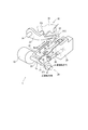
- FIG. 1 is a perspective view showing a shift-by-wire system according to the first embodiment
- FIG. 2 is a schematic configuration diagram illustrating a shift-by-wire system according to the first embodiment
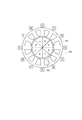
- FIG. 3 is a schematic diagram showing a stator and a rotor according to the first embodiment.
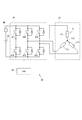
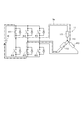
- FIG. 4 is a circuit diagram showing a motor winding and a drive circuit according to the first embodiment
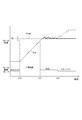
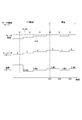
- FIG. 5 is a time chart illustrating motor drive control according to the first embodiment.
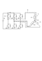
- FIG. 6 is a diagram illustrating an energization path during feedback control according to the first embodiment.
- FIG. 7 is a diagram illustrating an energization path during stop control by two-phase energization according to the reference example.
- FIG. 8 is an explanatory diagram illustrating an energization path during stop control according to the first embodiment.
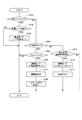
- FIG. 9 is a flowchart illustrating a motor drive control process according to the first embodiment.
- FIG. 10 is a time chart illustrating switching of the energized phase during stop control according to the first embodiment.
- FIG. 11 is a flowchart illustrating a motor drive control process according to the second embodiment.
- the shift-by-wire system 1 which is a shift range switching system, includes a motor 10, a shift range switching mechanism 20, a parking lock mechanism 30, a shift range control device 40, and the like.
- the motor 10 rotates by being supplied with electric power from a battery 45 mounted on a vehicle (not shown), and functions as a drive source of the shift range switching mechanism 20.
- the motor 10 of the present embodiment is a permanent magnet type DC brushless motor.
- the motor 10 has a stator 101, a rotor 105, and a motor winding 11 (see FIG. 4).
- the motor winding 11 has a U-phase coil 111, a V-phase coil 112, and a W-phase coil 113.
- Slot 102 is formed in stator 101.
- the number of slots in this embodiment is 12.
- the motor winding 11 is wound around the slot 102.
- the rotor 105 has a permanent magnet, and rotates integrally with a motor shaft (not shown) when the motor winding 11 is energized.
- the number of magnetic poles of the rotor 105 is eight. The number of slots and the number of magnetic poles can be appropriately designed.
- the encoder 13 as a motor rotation angle sensor detects the rotation position of the rotor 105.
- the encoder 13 is, for example, a magnetic rotary encoder, and includes a magnet that rotates integrally with the rotor, a Hall IC for detecting magnetism, and the like.
- the encoder 13 is a three-phase encoder that outputs an A-phase, a B-phase, and a C-phase pulse signal, which are pulse signals at predetermined angles, in synchronization with the rotation of the rotor.
- the speed reducer 14 is provided between the motor shaft of the motor 10 and the output shaft 15, and reduces the rotation of the motor 10 and outputs the rotation to the output shaft 15.
- the output shaft 15 is provided with an output shaft sensor 16 for detecting the angle of the output shaft 15.
- the output shaft sensor 16 of the present embodiment is, for example, a potentiometer.
- the shift range switching mechanism 20 has a detent plate 21, a detent spring 25, and the like, and applies a rotational driving force output from the reduction gear 14 to a manual valve 28 and a parking lock mechanism 30. Communicate to
- the detent plate 21 is fixed to the output shaft 15 and is driven by the motor 10.
- the direction in which the detent plate 21 moves away from the base of the detent spring 25 is defined as a forward rotation direction
- the direction in which the detent plate 21 approaches the base is defined as a reverse rotation direction.
- the detent plate 21 is provided with a pin 24 projecting in parallel with the output shaft 15.
- the pin 24 is connected to the manual valve 28.
- the shift range switching mechanism 20 converts the rotational movement of the motor 10 into a linear movement and transmits the linear movement to the manual valve 28.
- the manual valve 28 is provided on a valve body 29.
- concave portions 22 and 23 are provided on the detent spring 25 side of the detent plate 21.
- the side closer to the base of the detent spring 25 is referred to as the concave portion 22 and the side farther from the base is referred to as the concave portion 23.
- the concave portion 22 corresponds to a NotP range other than the P range
- the concave portion 23 corresponds to the P range.
- the detent spring 25 is a plate-like member that can be elastically deformed, and has a detent roller 26 at the tip.
- the detent spring 25 urges the detent roller 26 toward the center of rotation of the detent plate 21.
- a rotational force greater than a predetermined value is applied to the detent plate 21, the detent spring 25 is elastically deformed, and the detent roller 26 moves between the concave portions 22 and 23.
- the detent roller 26 fits into one of the recesses 22 and 23, the swing of the detent plate 21 is regulated, the axial position of the manual valve 28 and the state of the parking lock mechanism 30 are determined, and the automatic transmission is changed.
- the shift range of the machine 5 is fixed.
- the detent roller 26 fits into the concave portion 22 when the shift range is the NotP range, and fits into the concave portion 23 when the shift range is the P range.
- the parking lock mechanism 30 includes a parking rod 31, a cone 32, a parking lock pawl 33, a shaft 34, and a parking gear 35.
- the parking rod 31 is formed in a substantially L-shape, and one end 311 side is fixed to the detent plate 21.
- a cone 32 is provided on the other end 312 side of the parking rod 31, a cone 32 is provided.
- the conical body 32 is formed so as to decrease in diameter toward the other end 312 side. When the detent plate 21 swings in the reverse rotation direction, the cone 32 moves in the P direction.
- the parking lock pawl 33 is provided to be in contact with the conical surface of the conical body 32 and to be swingable about the shaft 34.
- a projection 331 that can mesh with the parking gear 35 is provided on the parking gear 35 side of the parking lock pole 33.
- the parking gear 35 is provided on an axle (not shown), and is provided so as to be able to mesh with the projection 331 of the parking lock pole 33.
- the rotation of the axle is restricted.
- the shift range is the NotP range
- the parking gear 35 is not locked by the parking lock pawl 33, and the rotation of the axle is not hindered by the parking lock mechanism 30.
- the shift range is the P range
- the parking gear 35 is locked by the parking lock pole 33, and the rotation of the axle is restricted.
- the shift range control device 40 includes a drive circuit 41, an ECU 50, and the like.
- the drive circuit 41 is a three-phase inverter for converting the power supplied from the battery 45, and the switching elements 411 to 416 are connected in a bridge.
- a relay 46 is provided between the battery 45 and the drive circuit 41.
- One end of the U-phase coil 111 is connected to a connection point of the U-phase switching elements 411 and 414 forming a pair.
- One end of the V-phase coil 112 is connected to a connection point of the V-phase switching elements 412 and 415 that form a pair.
- One end of the W-phase coil 113 is connected to a connection point of the W-phase switching elements 413 and 416 that form a pair.
- the other ends of the coils 111 to 113 are connected by a connection section 115.
- the switching elements 411 to 416 of the present embodiment are MOSFETs, other elements such as IGBTs may be used.
- the switching elements 411 to 413 connected to the high potential side are appropriately referred to as “upper arm elements”
- the switching elements 414 to 416 connected to the low potential side are appropriately referred to as “lower arm elements”.
- the ECU 50 is mainly configured by a microcomputer or the like, and includes a CPU, ROM, RAM, I / O, bus lines for connecting these components, and the like, which are not shown.
- Each process in the ECU 50 may be a software process by executing a program stored in advance in a substantial memory device such as a ROM (ie, a readable non-temporary tangible recording medium) by the CPU, or a dedicated process. Hardware processing by an electronic circuit may be used.
- the ECU 50 controls the on / off operation of the switching elements 411 to 416, and controls the motor 10 so that the driver requested shift range input by operating a shift lever or the like (not shown) matches the shift range of the shift range switching mechanism 20. Control the drive. Further, the ECU 50 controls the driving of the shift hydraulic control solenoid 6 based on the vehicle speed, the accelerator opening, the driver's requested shift range, and the like. The shift speed is controlled by controlling the shift hydraulic control solenoid 6. The number of shift hydraulic control solenoids 6 is provided in accordance with the number of shift stages.
- one ECU 50 controls the driving of the motor 10 and the solenoid 6, but the motor ECU for controlling the motor 10 for controlling the motor 10 and the AT-ECU for controlling the solenoid may be separated.
- the drive control of the motor 10 will be mainly described.
- the ECU 50 includes an angle calculation unit 51 and a drive control unit 55.
- the angle calculator 51 counts the pulse edges of each phase of the encoder signal output from the encoder 13 and calculates the encoder count value ⁇ en.
- the encoder count value ⁇ en is a value corresponding to the rotational position of the motor 10, and corresponds to “motor angle”.
- the drive control unit 55 generates a drive signal related to drive control of the motor 10 such that the encoder count value ⁇ en falls within the control range Rc including the target count value ⁇ cmd set according to the required shift range.
- the generated drive signal is output to the drive circuit 41.
- the target count value ⁇ cmd corresponds to the “target stop position”.
- FIG. 5 is a time chart for explaining the drive control of the motor 10.
- the horizontal axis is the common time axis
- the motor angle is shown in the upper part
- the motor drive mode is shown in the lower part.
- the feedback is appropriately described as “F / B”.
- the motor angle is shown as a count value of the encoder 13
- the target count value ⁇ cmd is shown by a one-dot chain line
- the encoder count value ⁇ en is shown by a solid line. Note that, for the sake of explanation, the lines are appropriately shifted. Also, the time scale and the like are appropriately changed, and do not always match the actual behavior.
- FIG. 5 illustrates an example in which the shift range is switched from the P range to the notP range.
- the motor drive mode is switched from the standby mode to the feedback control mode. Further, the target count value ⁇ cmd is set, and the motor 10 is driven such that the encoder count value ⁇ en becomes the target count value ⁇ cmd.
- the motor drive mode is switched from the feedback control mode to the stop control mode.
- FIG. 6 shows an example of an energized state immediately before switching to stop control. 6 to 8, the description of some components such as the relay 46 is omitted, and the energization path is indicated by a dashed line arrow Im.
- the energization pattern immediately before switching to the stop control is UV phase energization
- the U-phase upper arm element 411 is turned on
- the V-phase lower arm element 415 is turned on and off at a set duty.
- FIG. 5 shows an example in which overshoot occurs, an undershoot may occur depending on the power-off timing.
- step S101 The motor drive control processing of the present embodiment will be described based on the flowchart of FIG. This process is executed by the ECU 50 at a predetermined cycle (for example, 1 [ms]).
- a predetermined cycle for example, 1 [ms]
- step S101 the “step” of step S101 will be omitted, and will be simply referred to as a symbol “S”.
- S the other steps are the same.
- the drive control unit 55 determines whether the motor drive mode is the standby mode. If it is determined that the mode is not the standby mode (S101: NO), the process proceeds to S104. If it is determined that the mode is the standby mode (S101: YES), the process proceeds to S102.
- the drive control unit 55 determines whether or not the target shift range has been switched. If it is determined that the target range has not been switched (S102: NO), the process of S103 is not performed, the standby mode is maintained, and this routine ends. When it is determined that the target shift range has been switched (S102: YES), the process proceeds to S103, and the motor drive mode is switched to the feedback control mode.
- the drive control unit 55 determines whether the motor drive mode is the feedback control mode. When it is determined that the current mode is not the feedback control mode (S104: NO), the process proceeds to S109. When it is determined that the motor drive mode is the feedback control mode (S104: YES), the process proceeds to S105.
- the drive control unit 55 determines whether or not the encoder count value ⁇ en matches the target count value ⁇ cmd.
- the encoder count value ⁇ en is within a predetermined range including the target count value ⁇ cmd (for example, ⁇ 2 counts)
- the process proceeds to S106.
- the drive control unit 55 switches the motor drive mode to the stop control mode.
- the drive control unit 55 sets the energized phase based on the encoder count value ⁇ en.
- the two-phase upper arm element determined in S107 is turned on. As a result, the motor current flows between the drive circuit 41 and the motor winding 11.
- the drive control unit 55 determines whether or not the motor speed N has become equal to or less than the speed determination threshold Nth. to decide.
- the rotation speed determination threshold Nth is set according to a rotation speed at which the rotor 105 can be stopped within the control range Rc when all the switching elements 411 to 416 are turned off.
- Steps S107 and S108 will be described with reference to FIG.
- FIG. 10 shows the motor drive mode, the motor angle, the encoder pattern, and the energization pattern from the top, with the common time axis being the horizontal axis.
- the stop control is switched to when the encoder count value ⁇ en reaches the target count value ⁇ cmd.
- the encoder pattern is set to 0 to 6 according to the encoder count value ⁇ en. Then, an energization pattern is determined according to the set encoder pattern.
- the timing indicated by a white triangle is the execution timing of the motor drive control process in FIG. Note that the calculation of the encoder count value ⁇ en by the angle calculation unit 51 is interrupted every time a pulse edge of the encoder signal is detected.
- the shift range control device 40 of the present embodiment switches the shift range by controlling the drive of the motor 10 having the motor winding 11, and is a drive circuit 41 and a control unit. And an ECU 50.
- the drive circuit 41 has switching elements 411 to 416 provided corresponding to each phase of the motor winding.
- the ECU 50 drives the motor 10 by controlling the on / off operation of the switching elements 411 to 416, and stops the motor 10 at a target stop position corresponding to the target shift range. Specifically, the motor 10 is stopped such that the encoder count value ⁇ en is in the control range Rc including the target count value ⁇ cmd that is the target stop position.
- the switching elements 411 to 413 connected to the high potential side are upper arm elements, and the switching elements 414 to 416 connected to the lower potential side of the upper arm element are lower arm elements.
- the ECU 50 turns off all lower arm elements, turns on a predetermined number of upper arm elements, and circulates current between the motor winding 11 and the drive circuit 41. Let it.
- the motor 10 By circulating the current between the motor winding 11 and the drive circuit 41, the current is reduced and the kinetic energy of the motor 10 is consumed, so that the motor 10 can be stopped accurately at the target stop position. it can. In addition, since the power of the battery 45 is not used in the stop control, the power consumption for switching the range can be reduced.
- the ECU 50 switches the upper arm element to be turned on in accordance with a signal from the encoder 13 that detects the rotation angle of the motor 10. Thereby, the motor 10 can be stopped more appropriately.
- the motor winding 11 is a three-phase winding, and turns on the two upper arm elements in the stop control.
- One ends of the U-phase coil 111, the V-phase coil 112, and the W-phase coil 113, which are the respective phase windings constituting the motor winding 11, are connected by a connection portion 115.
- the current can be appropriately circulated.
- the motor 10 has a stator 101 around which the motor winding 11 is wound, and a rotor 105 which rotates when the motor winding 11 is energized.
- the rotor 105 has a magnet. Even when the rotor 105 has a magnet and the rotor 105 vibrates in the stop control due to the influence of the cogging torque, the vibration is attenuated by recirculating the current by the stop control, and the motor 10 is controlled. It can be stopped appropriately at the target stop position.
- FIG. 11 shows a second embodiment. This embodiment is different from the above-described embodiment in the motor drive control processing, and therefore, the description will be focused on this point.
- the motor drive control processing according to the present embodiment will be described with reference to the flowchart in FIG. FIG. 11 differs from FIG. 8 in that S119 is replaced with S119. Further, when the drive mode is set to the stop control mode in S106, time measurement from the start of the stop control is started.
- the drive control unit 55 determines whether the stop control continuation time has elapsed since the start of the stop control. Judge. When it is determined that the stop control continuation time has not elapsed (S119: NO), the process after S110 is not performed, the stop control mode is continued, and the present routine ends. When it is determined that the stop control duration time has elapsed (S109: YES), the process proceeds to S110.
- the stop control continuation time is set according to the time required to consume the motor current to such an extent that the rotor 105 can be stopped within the control range Rc when all the switching elements 411 to 416 are turned off.
- the ECU 50 turns off all the switching elements 411 to 416 when the stop control continuation time has elapsed since the start of the stop control.
- overshoot and undershoot after the end of the stop control can be prevented. Further, the same effects as those of the above embodiment can be obtained.
- the two-phase upper arm element is turned on in the stop control.
- the three-phase upper arm element may be turned on.
- the energized phase is switched according to the encoder count value.
- the on-state of the element that was turned on at the start of the stop control may be continued until the end of the stop control without switching the energized phase.
- the method of controlling the motor before the start of the stop control is not limited to the feedback control.
- the circuit configuration and the number of energized phases may be different from those in the above embodiment as long as the current can be circulated between the drive circuit and the motor winding.
- one set of the motor winding and the drive circuit are provided.
- a plurality of sets of motor windings and drive circuits may be provided.
- the motor rotation angle sensor that detects the rotation angle of the motor is a three-phase encoder.
- the motor rotation angle sensor may be a two-phase encoder, and is not limited to an encoder, and may be a resolver or the like.
- a potentiometer has been exemplified as the output shaft sensor.
- the output shaft sensor may be other than a potentiometer. Further, the output shaft sensor may be omitted.
- the detent plate is provided with two concave portions.
- the number of recesses is not limited to two, and for example, a recess may be provided for each range.
- the shift range switching mechanism, the parking lock mechanism, and the like may be different from those in the above embodiment.
- the speed reducer is provided between the motor shaft and the output shaft.
- the details of the reduction gear are not mentioned in the above embodiment, for example, a cycloid gear, a planetary gear, a gear using a spur gear that transmits torque from a reduction mechanism substantially coaxial with the motor shaft to the drive shaft, Any configuration may be used, such as a combination of the above.
- the speed reducer between the motor shaft and the output shaft may be omitted, or a mechanism other than the speed reducer may be provided.
- the present disclosure is not limited to the above embodiments, and can be implemented in various forms without departing from the gist of the present disclosure.
- control unit and the technique according to the present disclosure are implemented by a dedicated computer provided by configuring a processor and a memory programmed to execute one or more functions embodied by a computer program. May be done.
- control unit and the technique described in the present disclosure may be implemented by a dedicated computer provided by configuring a processor with one or more dedicated hardware logic circuits.
- control unit and the method according to the present disclosure may be implemented by a combination of a processor and a memory programmed to perform one or more functions and a processor configured by one or more hardware logic circuits. It may be realized by one or more dedicated computers configured.
- the computer program may be stored in a computer-readable non-transitional tangible recording medium as instructions to be executed by a computer.
Landscapes
- Engineering & Computer Science (AREA)
- General Engineering & Computer Science (AREA)
- Power Engineering (AREA)
- Mechanical Engineering (AREA)
- Gear-Shifting Mechanisms (AREA)
- Stopping Of Electric Motors (AREA)
Priority Applications (3)
| Application Number | Priority Date | Filing Date | Title |
|---|---|---|---|
| CN201980044537.9A CN112368933A (zh) | 2018-08-27 | 2019-08-19 | 换挡挡位控制装置 |
| DE112019004286.6T DE112019004286T5 (de) | 2018-08-27 | 2019-08-19 | Schaltbereich-Steuervorrichtung |
| US17/184,779 US20210180690A1 (en) | 2018-08-27 | 2021-02-25 | Shift range control device |
Applications Claiming Priority (2)
| Application Number | Priority Date | Filing Date | Title |
|---|---|---|---|
| JP2018158252A JP2020034013A (ja) | 2018-08-27 | 2018-08-27 | シフトレンジ制御装置 |
| JP2018-158252 | 2018-08-27 |
Related Child Applications (1)
| Application Number | Title | Priority Date | Filing Date |
|---|---|---|---|
| US17/184,779 Continuation US20210180690A1 (en) | 2018-08-27 | 2021-02-25 | Shift range control device |
Publications (1)
| Publication Number | Publication Date |
|---|---|
| WO2020045146A1 true WO2020045146A1 (ja) | 2020-03-05 |
Family
ID=69643906
Family Applications (1)
| Application Number | Title | Priority Date | Filing Date |
|---|---|---|---|
| PCT/JP2019/032276 WO2020045146A1 (ja) | 2018-08-27 | 2019-08-19 | シフトレンジ制御装置 |
Country Status (5)
Families Citing this family (1)
| Publication number | Priority date | Publication date | Assignee | Title |
|---|---|---|---|---|
| KR102263101B1 (ko) * | 2019-12-03 | 2021-06-09 | 주식회사 현대케피코 | 전동식 변속 레버 시스템의 모터 위치 학습 장치 및 위치 학습 방법 |
Citations (4)
| Publication number | Priority date | Publication date | Assignee | Title |
|---|---|---|---|---|
| JP2003235287A (ja) * | 2001-12-05 | 2003-08-22 | Matsushita Electric Ind Co Ltd | モータ駆動装置及びモータ駆動方法 |
| JP2016103874A (ja) * | 2014-11-27 | 2016-06-02 | コニカミノルタ株式会社 | モーター制御装置、シート搬送装置、画像形成装置、画像読取装置およびモーター制御方法 |
| JP2017184338A (ja) * | 2016-03-28 | 2017-10-05 | パナソニックIpマネジメント株式会社 | 車両制御装置、車両制御方法、および車両制御プログラム |
| JP2018040461A (ja) * | 2016-09-09 | 2018-03-15 | 株式会社デンソー | シフトレンジ制御装置 |
Family Cites Families (8)
| Publication number | Priority date | Publication date | Assignee | Title |
|---|---|---|---|---|
| JP2586771B2 (ja) * | 1992-03-06 | 1997-03-05 | ブラザー工業株式会社 | モータの駆動装置 |
| US5426355A (en) * | 1993-11-12 | 1995-06-20 | Exabyte Corporation | Power-off motor deceleration control system |
| JP4082164B2 (ja) * | 2002-10-07 | 2008-04-30 | 株式会社デンソー | モータ制御装置 |
| JP5421405B2 (ja) * | 2012-02-28 | 2014-02-19 | ファナック株式会社 | ダイナミックブレーキ制御手段を備えるモータ駆動装置 |
| JP5762582B1 (ja) * | 2014-02-04 | 2015-08-12 | 三菱電機株式会社 | シフトレンジ切り替え装置 |
| CN107408902B (zh) * | 2015-02-25 | 2020-03-24 | 本田技研工业株式会社 | 电力系统 |
| JP6398782B2 (ja) * | 2015-02-25 | 2018-10-03 | 株式会社デンソー | モータ制御装置 |
| JP6536465B2 (ja) * | 2016-04-26 | 2019-07-03 | 株式会社デンソー | シフトレンジ制御装置 |
-
2018
- 2018-08-27 JP JP2018158252A patent/JP2020034013A/ja active Pending
-
2019
- 2019-08-19 WO PCT/JP2019/032276 patent/WO2020045146A1/ja active Application Filing
- 2019-08-19 DE DE112019004286.6T patent/DE112019004286T5/de active Pending
- 2019-08-19 CN CN201980044537.9A patent/CN112368933A/zh not_active Withdrawn
-
2021
- 2021-02-25 US US17/184,779 patent/US20210180690A1/en not_active Abandoned
Patent Citations (4)
| Publication number | Priority date | Publication date | Assignee | Title |
|---|---|---|---|---|
| JP2003235287A (ja) * | 2001-12-05 | 2003-08-22 | Matsushita Electric Ind Co Ltd | モータ駆動装置及びモータ駆動方法 |
| JP2016103874A (ja) * | 2014-11-27 | 2016-06-02 | コニカミノルタ株式会社 | モーター制御装置、シート搬送装置、画像形成装置、画像読取装置およびモーター制御方法 |
| JP2017184338A (ja) * | 2016-03-28 | 2017-10-05 | パナソニックIpマネジメント株式会社 | 車両制御装置、車両制御方法、および車両制御プログラム |
| JP2018040461A (ja) * | 2016-09-09 | 2018-03-15 | 株式会社デンソー | シフトレンジ制御装置 |
Also Published As
| Publication number | Publication date |
|---|---|
| US20210180690A1 (en) | 2021-06-17 |
| JP2020034013A (ja) | 2020-03-05 |
| DE112019004286T5 (de) | 2021-05-20 |
| CN112368933A (zh) | 2021-02-12 |
Similar Documents
| Publication | Publication Date | Title |
|---|---|---|
| CN110337780B (zh) | 换挡挡位控制装置 | |
| JP6658416B2 (ja) | シフトレンジ制御装置 | |
| CN109075728B (zh) | 换挡挡位控制装置 | |
| US10844952B2 (en) | Shift range control apparatus | |
| CN109073073B (zh) | 换挡挡位控制装置 | |
| WO2018155333A1 (ja) | シフトレンジ制御装置 | |
| WO2017187789A1 (ja) | シフトレンジ制御装置 | |
| US11655894B2 (en) | Shift range control device | |
| CN111512074B (zh) | 换挡挡位控制装置 | |
| US11448316B2 (en) | Shift range control apparatus | |
| WO2020045146A1 (ja) | シフトレンジ制御装置 | |
| US12119762B2 (en) | Motor control device | |
| US11828362B2 (en) | Shift range control device | |
| US12104693B2 (en) | Shift range control device | |
| JP2019033620A (ja) | モータ制御装置 | |
| JP7363648B2 (ja) | モータ制御装置 | |
| US20220060138A1 (en) | Motor control device | |
| WO2020059676A1 (ja) | シフトレンジ制御装置 |
Legal Events
| Date | Code | Title | Description |
|---|---|---|---|
| 121 | Ep: the epo has been informed by wipo that ep was designated in this application |
Ref document number: 19854011 Country of ref document: EP Kind code of ref document: A1 |
|
| 122 | Ep: pct application non-entry in european phase |
Ref document number: 19854011 Country of ref document: EP Kind code of ref document: A1 |