WO2020045085A1 - 投影装置とその制御方法 - Google Patents
投影装置とその制御方法 Download PDFInfo
- Publication number
- WO2020045085A1 WO2020045085A1 PCT/JP2019/031881 JP2019031881W WO2020045085A1 WO 2020045085 A1 WO2020045085 A1 WO 2020045085A1 JP 2019031881 W JP2019031881 W JP 2019031881W WO 2020045085 A1 WO2020045085 A1 WO 2020045085A1
- Authority
- WO
- WIPO (PCT)
- Prior art keywords
- fan
- air
- state
- opening
- projection device
- Prior art date
- Legal status (The legal status is an assumption and is not a legal conclusion. Google has not performed a legal analysis and makes no representation as to the accuracy of the status listed.)
- Ceased
Links
Images





Classifications
-
- G—PHYSICS
- G03—PHOTOGRAPHY; CINEMATOGRAPHY; ANALOGOUS TECHNIQUES USING WAVES OTHER THAN OPTICAL WAVES; ELECTROGRAPHY; HOLOGRAPHY
- G03B—APPARATUS OR ARRANGEMENTS FOR TAKING PHOTOGRAPHS OR FOR PROJECTING OR VIEWING THEM; APPARATUS OR ARRANGEMENTS EMPLOYING ANALOGOUS TECHNIQUES USING WAVES OTHER THAN OPTICAL WAVES; ACCESSORIES THEREFOR
- G03B21/00—Projectors or projection-type viewers; Accessories therefor
-
- G—PHYSICS
- G03—PHOTOGRAPHY; CINEMATOGRAPHY; ANALOGOUS TECHNIQUES USING WAVES OTHER THAN OPTICAL WAVES; ELECTROGRAPHY; HOLOGRAPHY
- G03B—APPARATUS OR ARRANGEMENTS FOR TAKING PHOTOGRAPHS OR FOR PROJECTING OR VIEWING THEM; APPARATUS OR ARRANGEMENTS EMPLOYING ANALOGOUS TECHNIQUES USING WAVES OTHER THAN OPTICAL WAVES; ACCESSORIES THEREFOR
- G03B21/00—Projectors or projection-type viewers; Accessories therefor
- G03B21/14—Details
-
- G—PHYSICS
- G03—PHOTOGRAPHY; CINEMATOGRAPHY; ANALOGOUS TECHNIQUES USING WAVES OTHER THAN OPTICAL WAVES; ELECTROGRAPHY; HOLOGRAPHY
- G03B—APPARATUS OR ARRANGEMENTS FOR TAKING PHOTOGRAPHS OR FOR PROJECTING OR VIEWING THEM; APPARATUS OR ARRANGEMENTS EMPLOYING ANALOGOUS TECHNIQUES USING WAVES OTHER THAN OPTICAL WAVES; ACCESSORIES THEREFOR
- G03B21/00—Projectors or projection-type viewers; Accessories therefor
- G03B21/14—Details
- G03B21/16—Cooling; Preventing overheating
-
- H—ELECTRICITY
- H04—ELECTRIC COMMUNICATION TECHNIQUE
- H04N—PICTORIAL COMMUNICATION, e.g. TELEVISION
- H04N5/00—Details of television systems
- H04N5/74—Projection arrangements for image reproduction, e.g. using eidophor
-
- H—ELECTRICITY
- H04—ELECTRIC COMMUNICATION TECHNIQUE
- H04N—PICTORIAL COMMUNICATION, e.g. TELEVISION
- H04N9/00—Details of colour television systems
- H04N9/12—Picture reproducers
- H04N9/31—Projection devices for colour picture display, e.g. using electronic spatial light modulators [ESLM]
Definitions
- the present invention relates to a projection device and a control method thereof.
- a projector as a projection device has a light source, a light modulation element that spatially modulates light from the light source, and a member having a large temperature rise such as a power supply circuit, so that a fan for cooling these members with air is mounted. Is common.
- Patent Document 1 discloses that a housing constituting an exterior, an opening provided in the housing, and outside air are sucked into the housing by a forward rotation operation through the opening, and the inside of the housing is rotated by a reverse rotation operation.
- a projector is described that includes a fan that exhausts the air outside the electronic device, and a filter that is disposed between the opening and the fan and that prevents dust from entering the inside of the housing.
- Patent Literature 2 includes a cooling air generating unit that generates cooling air for cooling the display panel, and a cooling air supply pipe that guides the cooling air from the cooling air generating unit to at least one surface of the display panel.
- a projector is described.
- the cooling air supply pipe of the projector has a curved portion for removing dust contained in the cooling air by centrifugal force.
- Patent Literature 3 describes an electric apparatus including a ventilation hole provided in a housing, a filter for preventing dust from entering the housing, and a cooling fan disposed between the ventilation hole and the filter. Have been.
- the fan can be driven forward and reverse, and when the fan is rotated in the reverse direction to discharge the air inside the housing to the outside, the dust attached to the filter is removed by the cleaning means fixed to the fan. It is configured to be scraped off.
- the present invention has been made in view of the above circumstances, and in a configuration in which dust contained in sucked air is trapped in a curved portion using centrifugal force, dust adhered to the curved portion is removed, and the inside of the housing is removed. It is an object of the present invention to provide a projection apparatus capable of preventing dust from adhering to a member and a control method therefor.
- the projection device of the present invention includes a casing having an opening, a ventilation path for guiding air to a member to be cooled in the casing, and the air flowing from the opening to the ventilation path in a state of normal rotation. And a fan that discharges the air in the ventilation path from the opening in a state where the air is rotated in the reverse direction, and removes dust contained in the air that is taken into the ventilation path from the opening by centrifugal force.
- the control method of the projection apparatus includes a ventilation path for guiding air to a member to be cooled in a housing having an opening, and the air is taken into the ventilation path from the opening in a state of being rotated forward.
- a fan that discharges the air in the ventilation path from the opening in a reverse rotation state, and a centrifugal force to remove dust contained in the air taken into the ventilation path from the opening.
- a method of controlling a projection device comprising: a bending portion provided in the ventilation path, wherein a heating step of heating the bending portion; and, in a state where at least the bending portion is heated, reversely rotate the fan. And a control step.
- FIG. 1 is a schematic diagram illustrating a schematic configuration of a projector 100 that is an embodiment of a projection device of the present invention.
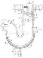
- FIG. 2 is a schematic sectional view showing a schematic configuration of a unit 70 of the projector 100 shown in FIG.
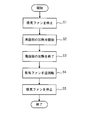
- FIG. 2 is a schematic sectional view showing a schematic configuration of a unit 70 of the projector 100 shown in FIG. 9 is a flowchart for explaining the operation of the processor of the system control unit 5 in the cleaning mode.
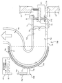
- FIG. 3 is a schematic diagram showing a schematic configuration of a unit 70A which is a first modification of the unit 70 in the projector 100 shown in FIG. FIG.
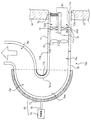
- FIG. 9 is a schematic diagram showing a schematic configuration of a unit 70B which is a second modification of the unit 70 in the projector 100 shown in FIG.
- FIG. 7 is a diagram showing a state in which an intake fan 75 of a unit 70B shown in FIG. 6 is rotated in reverse.
- FIG. 9 is a schematic diagram showing a schematic configuration of a unit 70C which is a third modification of the unit 70 in the projector 100 shown in FIG.
- FIG. 9 is a schematic diagram illustrating a schematic configuration of a unit 70D which is a fourth modification of the unit 70 in the projector 100 shown in FIG.
- FIG. 1 is a schematic diagram showing a schematic configuration of a projector 100 which is an embodiment of the projection device of the present invention.
- 2 and 3 are schematic cross-sectional views illustrating a schematic configuration of the unit 70 of the projector 100 illustrated in FIG.
- the projector 100 includes a housing 10 made of metal, resin, or the like, and a light source unit 2, a light modulation element 3, a projection optical system 4, a system control unit 5 provided inside the housing 10. , A unit 70 and an exhaust fan 8.
- the light source unit 2 includes a light source 21 that emits white light, a color wheel 22, and an illumination optical system 23.
- the light source 21 is configured to include a light emitting element such as a laser or an LED (Light Emitting Diode).
- the color wheel 22 is disposed between the light source 21 and the illumination optical system 23.
- the color wheel 22 is a disk-shaped member, and provided along its circumferential direction are an R filter that transmits red light, a G filter that transmits green light, and a B filter that transmits blue light.
- the color wheel 22 is rotated around an axis, and splits white light emitted from the light source 21 into red light, green light, and blue light in a time-sharing manner and guides the white light to the illumination optical system 23.
- Light emitted from the illumination optical system 23 enters the light modulation element 3.
- the light modulation element 3 spatially modulates the light emitted from the illumination optical system 23 based on the image data, and emits the spatially modulated light to the projection optical system 4.
- the projector 100 shown in FIG. 1 is an example in which a DMD (Digital Micromirror Device) is used as the light modulation element 3, but the light modulation element 3 is, for example, LCOS (Liquid Crystal on Silicon) or MEMS (Micro Electro Mechanical Systems). It is also possible to use an element, a liquid crystal display element, or the like.
- a DMD Digital Micromirror Device
- the light modulation element 3 is, for example, LCOS (Liquid Crystal on Silicon) or MEMS (Micro Electro Mechanical Systems). It is also possible to use an element, a liquid crystal display element, or the like.
- the projection optical system 4 receives the light from the light modulation element 3 and includes at least one lens. Light that has passed through the projection optical system 4 is projected on a screen (not shown) through an opening provided in the housing 10.
- the unit 70 is provided to capture dust contained in air taken into the inside of the housing 10 from the air inlet 10 ⁇ / b> A formed by the opening formed in the housing 10.
- the unit 70 includes a cylindrical case 71, a wall 71 a provided inside the case 71, a filter 72, a first flow path switching mechanism 73, and a second flow path.
- a switching mechanism 74, an intake fan 75, a ventilation path 76, and a heating unit 80 are provided.
- the case 71 is fitted to the intake port 10A of the housing 10, and has an opening 71A facing the intake port 10A, and an opening 71B opposite to the opening 71A.
- the opening 71B communicates with the inside of the tubular ventilation passage 76.
- the rotation direction of the intake fan 75 can be switched between forward and reverse.
- the intake fan 75 takes in air from the intake port 10A into the housing 10 through a first flow path CH1 and a ventilation path 76, which will be described later.
- the air in the housing 10 is discharged from the air inlet 10A through the ventilation passage 76 and a second flow channel CH2 described later.
- FIG. 2 shows a state in which the intake fan 75 is rotating forward
- FIG. 3 shows a state in which the intake fan 75 is rotating reversely.
- the air taken into the case 71 from the intake port 10A by the forward rotation of the intake fan 75 is introduced into the tubular ventilation path 76 from the opening 71B of the case 71 through a first flow path CH1 described later.
- the air introduced into the ventilation passage 76 is guided to a member to be cooled such as the light source 21, the light modulation element 3, or a power supply circuit (not shown) to cool them.
- the intake fan 75 is controlled by the system control unit 5.
- the intake port 10A constitutes an opening, and the intake fan 75 constitutes a fan.
- a portion of the hollow portion of the case 71 between the intake fan 75 and the opening 71A is separated into two, a first flow channel CH1 and a second flow channel CH2, by a wall portion 71a.
- the first flow path CH1 is a flow path that connects the intake port 10A and the intake fan 75.
- the second channel CH2 is a channel that connects the intake port 10A and the intake fan 75, and is a channel different from the first channel CH1.
- the first flow path switching mechanism 73 is formed in the first flow path CH1, and in the state shown in FIG. 2 in which the intake fan 75 is rotating forward, the air W1 taken into the first flow path CH1 from the intake port 10A. In the state shown in FIG. 3 in which the intake fan 75 rotates in the reverse direction, the air W2 in the ventilation path 76 is blocked from passing through the first flow path CH1.
- the first flow path switching mechanism 73 is constituted by, for example, a check valve that allows air flowing in a direction from the intake port 10A to the intake fan 75 to pass therethrough and does not allow air flowing in the opposite direction to this direction to pass.
- the first flow path switching mechanism 73 opens the first flow path CH1 when the intake fan 75 is rotating forward, and opens the first flow path CH1 when the intake fan 75 is rotating reversely. May be configured by a shutter mechanism for closing the shutter.
- the second flow path switching mechanism 74 is formed in the second flow path CH2, and is taken into the second flow path CH2 from the intake port 10A in the state shown in FIG. 2 in which the intake fan 75 is rotating forward. In the state shown in FIG. 3 in which the passage of the air W1 is blocked and the intake fan 75 is rotating in the reverse direction, the air W2 from the ventilation passage 76 passes through the intake port 10A.
- the second flow path switching mechanism 74 is configured by, for example, a check valve that shuts off air flowing in a direction from the intake port 10A toward the intake fan 75 and allows air flowing in a direction opposite to this direction to pass.
- the second flow path switching mechanism 74 closes the second flow path CH2 when the intake fan 75 is rotating in the forward direction, and closes the second flow path CH2 when the intake fan 75 is rotating in the reverse direction. It may be constituted by a shutter mechanism that opens the path CH2.
- the filter 72 is provided at a position closer to the opening 71A than the first flow path switching mechanism 73 in the first flow path CH1.
- the filter 72 is for catching dust contained in the air flowing into the first flow channel CH1 from the intake port 10A, and is, for example, a flat and mesh member that closes the first flow channel CH1.
- the ventilation passage 76 has a straight linear portion 76a communicating with the opening 71B of the case 71, a curved portion 76b curved with respect to the straight portion 76a, and an end of the curved portion 76b opposite to the straight portion 76a. And an extension 76c extending from this end to direct the air flowing out of the end in a desired direction.
- the curved portion 76b is a semicircular portion extending along a circle from the boundary (dashed line in the figure) with the straight portion 76a. The air that has flowed into the ventilation passage 76 from the opening 71B of the case 71 while the intake fan 75 is rotating forward reaches the curved portion 76b through the straight portion 76a.
- the dust contained in the air is trapped and removed by the inner wall 76w outside the curved portion 76b by centrifugal force when passing through the curved portion 76b.
- the inner wall 76w outside the curved portion 76b refers to the wall surface of the curved portion 76b on the side of the direction in which the centrifugal force generated when air flows through the curved portion 76b.
- the heating unit 80 heats the curved portion 76b, and has a plate-shaped and semicircular heat transfer member 77 fixed to the back surface of the inner wall 76w in the curved portion 76b, and a columnar shape fixed to the heat transfer member 77. And a heater 78 connected to the heat transfer member 79.
- the heat transfer member 77 and the heat transfer member 79 are each made of a material such as a metal having a high thermal conductivity.
- the heater 78 is configured to include a heating element that generates heat when energized.
- the heater 78 is controlled by the system control unit 5.
- the heat generated by the heater 78 is transmitted from the heat transfer member 79 to the heat transfer member 77. Since the heat transfer member 77 is fixed to the back surface of the inner wall 76w of the ventilation path 76, the heat transmitted from the heater 78 heats the curved portion 76b including the inner wall 76w.
- the exhaust fan 8 shown in FIG. 1 is provided at a position facing the exhaust port 10B formed by the opening formed in the housing 10, and discharges the air in the housing 10 from the exhaust port 10B.
- the exhaust fan 8 is controlled by the system control unit 5.
- a filter (not shown) is fitted to the exhaust port 10B, and the filter prevents dust from entering the housing 10 from the exhaust port 10B.
- the system control unit 5 shown in FIG. 1 performs control of the light source unit 2, control of the light modulation element 3, control of the unit 70, control of the exhaust fan 8, and the like, and includes a processor and a ROM (Read Only Memory). And a RAM (Random Access Memory).
- a programmable logic device CPU (Central Processing Unit), which is a general-purpose processor for executing various processes by executing a program, or a processor capable of changing a circuit configuration after manufacturing, such as an FPGA (Field Programmable Gate Array).
- a dedicated electric circuit which is a processor having a circuit configuration specifically designed to execute a specific process such as Programmable Logic Device (PLD) or ASIC (Application Specific Integrated Circuit), is included.
- PLD Programmable Logic Device
- ASIC Application Specific Integrated Circuit
- the structure of these processors is more specifically an electric circuit combining circuit elements such as semiconductor elements.
- the processor of the system control unit 5 may be configured by one of the various processors described above, or a combination of two or more processors of the same type or different types (for example, a combination of a plurality of FPGAs or a combination of a CPU and an FPGA). Combination).
- the processor of the system control unit 5 forms a control unit.
- first flow path switching mechanism 73 and the second flow path switching mechanism 74 are check valves.
- the projector 100 is provided with a cleaning mode for removing dust captured on the inner wall 76w of the curved portion 76b of the unit 70, in addition to a projection mode for projecting an image on a screen.
- This cleaning mode can be automatically started, for example, when an operation of turning off the power of the projector 100 is performed, or can be manually started.
- the processor of the system control unit 5 causes the intake fan 75 to rotate forward as shown in FIG.
- the air W1 taken from the intake port 10A and flowing into the opening 71A of the case 71 does not pass through the second flow path CH2 but passes through the first flow path CH1.
- the dust contained in the air W1 is captured by the filter 72 and is captured by the inner wall 76w of the curved portion 76b of the ventilation passage 76. Therefore, intrusion of the dust into the inside of the housing 10 is prevented.
- FIG. 4 is a flowchart for explaining the operation of the processor of the system control unit 5 in the cleaning mode.
- the processor of the system control unit 5 shifts, for example, from the projection mode to the cleaning mode, the processor first stops the intake fan 75 (step S1).
- the processor of the system control unit 5 energizes the heater 78 to start heating the bending portion 76b (step S2).
- the processor of the system control unit 5 stops energizing the heater 78 and ends the heating of the bending portion 76b (step S3).
- the dust containing water or oil adhered to the inner wall 76w of the curved portion 76b is dried, and the dust is easily peeled off from the inner wall 76w.
- the processor of the system control unit 5 rotates the intake fan 75 in the reverse direction (step S4).
- the air W2 from the inside of the housing 10 flows into the ventilation path 76, flows into the case 71 through the extending portion 76c, the curved portion 76b, and the straight portion 76a. I do. Further, the air W2 passes through the second channel CH2 and is discharged from the intake port 10A.
- the air passage 76 has a configuration in which the air flowing from the inside of the housing 10 to the inside of the case 71 is less affected by centrifugal force in the curved portion 76b than the air flowing from the inside of the case 71 to the inside of the housing 10. I have. For this reason, the dust trapped on the inner wall 76w of the curved portion 76b is peeled off from the inner wall 76w by the air W2 flowing from the inside of the housing 10 to the inside of the case 71 and is carried to the case 71, from which the air inlet 10A Is discharged out of
- the processor of the system control unit 5 stops the intake fan 75 when a predetermined time has elapsed after starting the reverse rotation of the intake fan 75 (step S5), and ends the cleaning mode.
- the processor of the system control unit 5 controls the first channel switching mechanism 73 in the projection mode. Is controlled to open the first channel CH1, and the second channel switching mechanism 74 is controlled to close the second channel CH2. Further, in the cleaning mode, the processor of the system control unit 5 controls the first flow path switching mechanism 73 to close the first flow path CH1 while the processing from step S1 to step S3 in FIG. 4 is performed. The second channel switching mechanism 74 is controlled to open the second channel CH2. After that, the processing after step S4 is performed.
- the intake fan 75 is rotated in the reverse direction.
- the dust containing water, oil, or the like adhered to the curved portion 76b is dried and easily peeled off from the inner wall 76w. Therefore, the dust can be easily discharged out of the intake port 10A by the air W2 generated by the reverse rotation of the intake fan 75 after the heat treatment.
- the projection mode it is possible to prevent the dust from entering the inside of the housing 10 and improve the quality of the projected image.
- the air W1 taken in from the intake port 10A flows into the ventilation path 76 only through the first flow path CH1. Since the filter 72 is disposed in the first channel CH1, dust contained in the air W1 can be captured by the filter 72. Dust that cannot be captured by the filter 72 is captured by the inner wall 76w of the curved portion 76b of the ventilation path 76. As described above, since dust is captured at two places in the passage of the air W1, dust can be prevented from adhering to the optical components inside the housing 10.
- the air W2 taken into the ventilation path 76 from the inside of the housing 10 passes only through the second flow path CH2 and is discharged outside from the intake port 10A. Since there is no filter in the passage of the air W2, the effect of removing dust contained in the air W2 can be enhanced. Further, since the air W2 does not enter the surface of the filter 72 on the intake fan 75 side, clogging of the filter 72 can be prevented, and a sufficient amount of intake air in the projection mode can be ensured.
- the curved portion 76b is heated in a state where the intake fan 75 is stopped, and after the heating is completed, the reverse rotation of the intake fan 75 is started.
- the period in which the curved portion 76b is heated and the period in which the air flow is generated in the ventilation path 76 due to the reverse rotation of the intake fan 75 are not overlapped, so that the drying of the curved portion 76b is efficiently performed. Can be done.
- the processor of the system control unit 5 overlaps the period in which the curved portion 76b is heated and the period in which the intake fan 75 is rotated in the reverse direction in the cleaning mode. Control may be performed.
- step S4 is performed after step S1, then steps S2 and S3 are performed, and then step S5 is performed, or steps S4 and S2 are performed simultaneously after step S1, Thereafter, the processing of step S3 and step S5 may be performed simultaneously.
- FIG. 5 is a schematic diagram showing a schematic configuration of a unit 70A which is a first modification of the unit 70 in the projector 100 shown in FIG. 1, and is a diagram showing a state where the intake fan 75 is rotated forward.
- the unit 70A has the same configuration as the unit 70 except that the heating unit 80 is changed to the heating unit 80A.
- the same components as those in FIG. 5 are identical to FIG. 5 in FIG. 5, the same components as those in FIG.
- the heating unit 80A is different from the heating unit 80 in that the heater 78 is omitted, and the end of the heat transfer member 79 opposite to the end in contact with the heat transfer member 77 is housed in the housing 10. It is configured to be fixed to a heat sink 91 which is a heat radiating member for radiating heat of the cooled member 90 fixed to the cooled member 90 such as the light source 21, the light modulation element 3, or the power supply circuit.
- the air W1 flows into the housing 10 from the ventilation passage 76, and the heat sink 91 and the member to be cooled 90 are cooled by the air W1.
- the temperature rise of the heat sink 91 is suppressed by the cooling effect of the air W1. Therefore, a large amount of heat is not transmitted to the heat transfer member 77 that is in contact with the heat sink 91 via the heat transfer member 79, and the curved portion 76b is not heated.
- the power for heating can be reduced. Further, since there is no need to provide a device for heating, it is possible to reduce the manufacturing cost and reduce the size of the projector 100.
- FIG. 6 is a schematic diagram showing a schematic configuration of a unit 70B which is a second modification of the unit 70 in the projector 100 shown in FIG. 1, and is a diagram showing a state where the intake fan 75 is rotating forward.
- the unit 70B has the same configuration as the unit 70 except that the heating unit 80 is changed to the heating unit 80B. 6, the same components as those in FIG. 2 are denoted by the same reference numerals, and description thereof will be omitted.
- FIG. 7 is a diagram illustrating a state in which the intake fan 75 of the unit 70B illustrated in FIG. 6 is rotated in the reverse direction.
- the heating unit 80B is different from the heating unit 80 in that the heater 78 is eliminated, the heat transfer member 79 is changed to a structure including a heat transfer member 79c and a heat transfer member 79d, and a drive unit 79e is added. I have.
- the heat transfer member 79 c is an L-shaped and cylindrical member, and one end thereof is fixed to the heat transfer member 77.
- the heat transfer member 79d is extendably supported inside the other end of the heat transfer member 79c. At a position facing the heat transfer member 79d, a light source 21, a light modulation element 3, or a heat sink 91 fixed to a member to be cooled 90 such as a power supply circuit is disposed.
- the heat transfer member 79c and the heat transfer member 79d are each made of a material such as a metal having a high thermal conductivity.
- the drive unit 79e is an actuator such as a motor or a solenoid for driving the heat transfer member 79d.
- the drive unit 79e In response to a command from the system control unit 5, the drive unit 79e extends the heat transfer member 79d, contacts the heat transfer member 79d with the heat sink 91, and forms a heat transfer path from the heat sink 91 to the curved portion 76b (FIG. 7). (See FIG. 6) and a state in which the heat transfer member 79d is contracted to separate the heat transfer member 79d from the heat sink 91 to block the heat transfer path from the heat sink 91 to the curved portion 76b.
- the heat transfer member 77, the heat transfer member 79c, and the heat transfer member 79d form a movable heat transfer member that forms and blocks a heat transfer path from the heat sink 91 to the curved portion 76b.
- step S2 in the flowchart shown in FIG. 4 the processor of the system control unit 5 of the projector 100 having the unit 70B having the above-described configuration controls the driving unit 79e to bring the heat transfer member 79d into contact with the heat sink 91. Let it. By this control, the heat transmitted from the member to be cooled 90 to the heat sink 91 is transmitted to the heat transfer member 77, and the curved portion 76b is heated.
- the processor of the system control unit 5 controls the driving unit 79e to separate the heat transfer member 79d from the heat sink 91.
- the heat transmitted from the member to be cooled 90 to the heat sink 91 is not transmitted to the heat transfer member 77, and the heating of the curved portion 76b ends.
- the heat sink 91 and the curved portion 76b can be connected by the heat transfer members 77, 79c, and 79d only when it is desired to heat the curved portion 76b. Therefore, it is possible to reliably prevent the temperature of the curved portion 76b from rising in the projection mode, and to prevent dust containing water or oil from coming off the inner wall 76w and entering the inside of the housing 10. Can be.
- the heating unit 80B has a configuration in which the end of the heat transfer member 79c opposite to the heat transfer member 77 side is fixed to the heat sink 91, and the heat transfer member 79d has an end on the heat transfer member 77 side of the heat transfer member 79c. May be provided, and the heat transfer member 79d may be moved in a state of being in contact with the heat transfer member 77 and in a state of being separated from the heat transfer member 77.
- FIG. 8 is a schematic diagram showing a schematic configuration of a unit 70C which is a third modification of the unit 70 in the projector 100 shown in FIG. 1, and shows a state where the intake fan 75 is rotated in the reverse direction.
- the unit 70C has the same configuration as the unit 70 except that a vibration unit 82 is added. 8, the same components as those in FIG. 3 are denoted by the same reference numerals, and the description will be omitted.
- the vibrating section 82 is a device for vibrating the bending section 76b, and includes, for example, an ultrasonic vibrator and a drive element for driving the vibrator.
- the vibration unit 82 is controlled by the system control unit 5.
- the processor of the system control unit 5 of the projector 100 having the unit 70C activates the vibration unit 82 to vibrate the bending portion 76b while the intake fan 75 is rotating in the reverse direction. On the other hand, the processor of the system control unit 5 stops the vibration unit 82 while the intake fan 75 is rotating forward or stopped.
- the vibration unit 82 is provided is also applicable to each of the unit 70A and the unit 70B.
- FIG. 9 is a schematic diagram showing a schematic configuration of a unit 70D which is a fourth modification of the unit 70 in the projector 100 shown in FIG. 1, and is a diagram showing a state where the intake fan 75 is rotated forward.
- the unit 70D has the same configuration as the unit 70 except that a plate-shaped and semicircular heat transfer member 77a fixed to the back surface of the inner inner wall 761w in the curved portion 76b is added.
- the inner wall 761w inside the curved portion 76b refers to the wall surface of the curved portion 76b on the opposite side to the direction in which the centrifugal force generated when air flows through the curved portion 76b.
- the heat transfer member 77a of the unit 70D shown in FIG. 9 is fixed to the heat transfer member 79, although not shown.
- dust particles adhere to the inner wall 761w inside the curved portion 76b due to the turbulence of the air W1.
- the configuration for heating the rear portion of the inner wall 761w shown in the unit 70D can be similarly applied to the units 70A, 70B, and 70C.
- the filter 72, the first channel switching mechanism 73, and the second channel switching mechanism 74 in the case 71 are not essential and may be omitted. Good. Even in this case, since the dust contained in the air taken into the ventilation passage 76 from the intake port 10A is captured by the curved portion 76b, it is possible to prevent the dust from entering the inside of the housing 10.
- a housing having an opening; A ventilation path for guiding air to the member to be cooled in the housing, A fan that takes in the air from the opening to the ventilation path in the state of normal rotation and discharges the air in the ventilation path from the opening in the state of reverse rotation, A curved portion provided in the ventilation path for removing dust contained in the air taken into the ventilation path from the opening by centrifugal force, A heating section for heating the bending section, A control unit configured to reversely rotate the fan in a state where at least the bending unit is heated.
- the heat transfer member is a movable member that takes a state of being in contact with each of the heat radiating member and the curved portion, and a state of being separated from one of the heat radiating member and the curved portion, In a state where the heat transfer member is in contact with each of the heat dissipating member and the curved portion, the heat is transmitted to the curved portion, and the heat transfer member is separated from any one of the heat dissipating member and the curved portion.
- a projection device in which transmission of the heat to the bending portion is blocked in a state.
- a projection apparatus further comprising a vibrating section that vibrates the bending section when the fan is rotating in the reverse direction.
- the projection device according to any one of (1) to (6), A first flow path connecting the opening and the fan, A second flow path different from the first flow path connecting the opening and the fan, A filter for capturing dust provided in the first flow path, When the fan is rotating forward, the air taken in from the opening is allowed to pass, and when the fan is rotating in the reverse direction, the passage of the air in the ventilation passage is blocked.
- a first channel switching mechanism formed in one channel, In the state where the fan is rotating forward, the passage of the air taken in from the opening is blocked, and when the fan is rotating in the reverse direction, the air in the ventilation passage passes through the opening.
- a second flow path switching mechanism formed in the second flow path.
- the projection device according to any one of (1) to (7), The projection device, wherein the member to be cooled is at least one of a light source and a light modulation element.
- a control method of the projection device comprising: A heating step of heating the curved portion, A control step of reversely rotating the fan in a state where at least the bending portion is heated.
- the method for controlling a projection device is a first flow path connecting the opening and the fan, a first flow path provided with a filter for capturing dust, and the first flow path connecting the opening and the fan.
- a different second flow path In a state where the fan is rotating forward, the air taken in from the opening is allowed to pass through the first flow path to the fan, and the air is blocked from passing through the second flow path. In a rotating state, a projection device that blocks passage of the air in the ventilation path in the first flow path, and passes the air in the ventilation path from the second flow path to the opening. Control method.
- the present invention is highly convenient and effective when applied to a liquid crystal projector or the like.
Landscapes
- Physics & Mathematics (AREA)
- General Physics & Mathematics (AREA)
- Engineering & Computer Science (AREA)
- Multimedia (AREA)
- Signal Processing (AREA)
- Projection Apparatus (AREA)
- Video Image Reproduction Devices For Color Tv Systems (AREA)
- Cooling Or The Like Of Electrical Apparatus (AREA)
- Transforming Electric Information Into Light Information (AREA)
Abstract
吸引した空気に含まれる粉塵を遠心力を利用して湾曲部に捕捉する構成において、湾曲部に密着した粉塵を取り除いて、筐体内部の部材への粉塵の付着を防ぐことのできる投影装置とその制御方法を提供する。 プロジェクタ100は、吸気口10Aを有する筐体10と、筐体10内の光源21等の被冷却部材に空気を導くための通風路76と、正回転されている状態においては吸気口10Aから通風路76に空気を取り込み、逆回転されている状態においては通風路76内の空気を吸気口10Aから排出する吸気ファン75と、吸気口10Aから通風路76に取り込まれる空気に含まれる粉塵を遠心力によって除去するための通風路76に設けられた湾曲部76bと、湾曲部76bを加熱する加熱部80と、少なくとも湾曲部76bが加熱された状態にて吸気ファン75を逆回転させるシステム制御部5と、を備える。
Description
本発明は、投影装置とその制御方法に関する。
投影装置としてのプロジェクタは、光源、光源からの光を空間変調する光変調素子、及び電源回路等の温度上昇の大きい部材を有するため、これらの部材を空気によって冷却するためのファンを搭載するのが一般的である。
特許文献1には、外装を構成する筐体と、筐体に設置される開口部と、開口部を介して、正回転動作により外気を筐体内部に吸入し、逆回転動作により筐体内部の空気を電子機器の外部へ排気するファンと、開口部とファンとの間に配置され、塵埃の筐体内部への侵入を防ぐフィルタと、を備えるプロジェクタが記載されている。
特許文献2には、表示パネルを冷却するための冷却風を発生させる冷却風発生手段と、冷却風を、冷却風発生手段から表示パネルの少なくとも一つの面へと導く冷却風供給管とを備えるプロジェクタが記載されている。このプロジェクタの冷却風供給管は、冷却風に含まれる粉塵を遠心力によって取り除くための湾曲部を有している。
特許文献3には、筐体に設けられた通風孔と、筐体内部に塵埃が侵入するのを防止するフィルタと、これらの間に配置された冷却用のファンと、を備える電気機器が記載されている。この電子機器では、ファンが正逆回転駆動可能であり、ファンを逆回転させて筐体内部の空気を外部に排出する場合には、ファンに固定された清掃手段によって、フィルタに付着した塵埃が掻き取られる構成となっている。
特許文献2に記載されたように、冷却風供給管の湾曲部に粉塵を付着させる構成では、この湾曲部の定期的な清掃が必要になる。この清掃の一手法として、特許文献1に記載されているように、冷却風を発生させるためのファンを逆回転させて、湾曲部に付着している粉塵を、冷却風の流入口から排出する方法が考えられる。
しかし、筐体内部にて発生した結露又は粉塵が持つ油分等によって、粉塵が湾曲部に密着していると、ファンの逆回転による空気の排出だけでは、湾曲部に密着した粉塵を除去することは難しい。特許文献3に記載されているような清掃手段による粉塵の掻き取りを採用しても、水分又は油分を持つ粉塵を充分に除去することは困難である。こうして除去しきれなかった水分又は油分を持つ粉塵が後に乾燥すると、この粉塵が剥がれ落ち、冷却風に乗って光学部品等に付着し、投影画像の品質に影響を与える可能性がある。
本発明は、上記事情に鑑みてなされたものであり、吸引した空気に含まれる粉塵を遠心力を利用して湾曲部に捕捉する構成において、湾曲部に密着した粉塵を取り除いて、筐体内部の部材への粉塵の付着を防ぐことのできる投影装置とその制御方法を提供することを目的とする。
本発明の投影装置は、開口部を有する筐体と、上記筐体内の被冷却部材に空気を導くための通風路と、正回転されている状態においては上記開口部から上記通風路に上記空気を取り込み、逆回転されている状態においては上記通風路内の上記空気を上記開口部から排出するファンと、上記開口部から上記通風路に取り込まれる上記空気に含まれる粉塵を遠心力によって除去するための上記通風路に設けられた湾曲部と、上記湾曲部を加熱する加熱部と、少なくとも上記湾曲部が加熱された状態にて、上記ファンを逆回転させる制御部と、を備えるものである。
本発明の投影装置の制御方法は、開口部を有する筐体内の被冷却部材に空気を導くための通風路と、正回転されている状態においては上記開口部から上記通風路に上記空気を取り込み、逆回転されている状態においては上記通風路内の上記空気を上記開口部から排出するファンと、上記開口部から上記通風路に取り込まれる上記空気に含まれる粉塵を遠心力によって除去するための上記通風路に設けられた湾曲部と、を有する投影装置の制御方法であって、上記湾曲部を加熱する加熱ステップと、少なくとも上記湾曲部が加熱された状態にて、上記ファンを逆回転させる制御ステップと、を備えるものである。
本発明によれば、吸引した空気に含まれる粉塵を遠心力を利用して湾曲部に捕捉する構成において、湾曲部に密着した粉塵を取り除いて、筐体内部の部材への粉塵の付着を防ぐことのできる投影装置とその制御方法を提供することができる。
以下、本発明の実施形態について図面を参照して説明する。
図1は、本発明の投影装置の一実施形態であるプロジェクタ100の概略構成を示す模式図である。図2及び図3は、図1に示すプロジェクタ100のユニット70の概略構成を示す断面模式図である。
図1に示すように、プロジェクタ100は、金属又は樹脂等からなる筐体10と、筐体10の内部に設けられた、光源ユニット2、光変調素子3、投影光学系4、システム制御部5、ユニット70、及び排気ファン8を備える。
光源ユニット2は、白色光を出射する光源21と、カラーホイール22と、照明光学系23と、を備える。光源21は、レーザ又はLED(Light Emitting Diode)等の発光素子を含んで構成される。カラーホイール22は、光源21と照明光学系23の間に配置されている。カラーホイール22は、円板状の部材であり、その周方向に沿って、赤色光を透過するRフィルタ、緑色光を透過するGフィルタ、及び青色光を透過するBフィルタが設けられている。カラーホイール22は軸周りに回転され、光源21から出射される白色光を時分割にて赤色光、緑色光、及び青色光に分光して照明光学系23に導く。照明光学系23から出射された光は光変調素子3に入射される。
光変調素子3は、照明光学系23から出射された光を画像データに基づいて空間変調し、空間変調した光を投影光学系4に出射する。
図1に示すプロジェクタ100は、光変調素子3としてDMD(Digital Micromirror Device)を用いた例であるが、光変調素子3としては、例えば、LCOS(Liquid crystal on silicon)、MEMS(Micro Electro Mechanical Systems)素子、又は液晶表示素子等を用いることも可能である。
投影光学系4は、光変調素子3からの光が入射されるものであり、少なくとも1つのレンズを含む。投影光学系4を通過した光は筐体10に設けられた開口を通って図示省略のスクリーンに投射される。
ユニット70は、筐体10に形成された開口部によって構成される吸気口10Aから筐体10の内部に取り込まれる空気に含まれる粉塵を捕捉するために設けられている。
図2及び図3に示すように、ユニット70は、筒状のケース71と、ケース71の内部に設けられた壁部71a、フィルタ72、第一の流路切替機構73、第二の流路切替機構74、及び吸気ファン75と、通風路76と、加熱部80と、を備える。
ケース71は、筐体10の吸気口10Aに嵌合されており、吸気口10Aに対向する開口71Aと、この開口71Aと反対側の開口71Bとを備える。開口71Bは、管状の通風路76の内部と連通している。
吸気ファン75は、その回転方向を正逆切替可能となっている。吸気ファン75は、一方向に回転(正回転)されている状態においては、吸気口10Aから後述の第一流路CH1及び通風路76を介して筐体10内に空気を取り込み、この一方向の反対方向に回転(逆回転)されている状態においては、筐体10内の空気を、通風路76及び後述の第二流路CH2を介して吸気口10Aから排出する。
なお、図2は、吸気ファン75が正回転されている状態を示しており、図3は、吸気ファン75が逆回転されている状態を示している。
吸気ファン75が正回転することによって吸気口10Aからケース71内に取り込まれた空気は、後述する第一流路CH1を通って、ケース71の開口71Bから管状の通風路76に導入される。通風路76に導入された空気は、例えば光源21、光変調素子3、又は図示省略の電源回路等の被冷却部材に導かれて、これらを冷却する。
吸気ファン75が逆回転することによって筐体10内部から通風路76に取り込まれた空気は、ケース71の開口71Bからケース71内に導入される。ケース71内に導入された空気は、後述する第二流路CH2を通って、吸気口10Aから外部に排出される。
吸気ファン75はシステム制御部5によって制御される。プロジェクタ100において、吸気口10Aは開口部を構成し、吸気ファン75はファンを構成する。
ケース71の中空部における吸気ファン75と開口71Aとの間の部分は、壁部71aによって第一流路CH1と第二流路CH2の2つに分離されている。第一流路CH1は、吸気口10Aと吸気ファン75とを繋ぐ流路である。第二流路CH2は、吸気口10Aと吸気ファン75とを繋ぐ流路であり、且つ、第一流路CH1とは異なる流路である。
第一の流路切替機構73は、第一流路CH1に形成されており、吸気ファン75が正回転している図2に示す状態においては、吸気口10Aから第一流路CH1に取り込まれる空気W1を通過させて通風路76まで到達させ、吸気ファン75が逆回転している図3に示す状態においては、通風路76内の空気W2の第一流路CH1における通過を遮断する機構である。
第一の流路切替機構73は、例えば、吸気口10Aから吸気ファン75に向かう方向に流れる空気は通過させ、この方向の逆方向に流れる空気は通過させない逆止弁によって構成される。または、第一の流路切替機構73は、例えば、吸気ファン75が正回転されている状態においては第一流路CH1を開放し、吸気ファン75が逆回転されている状態においては第一流路CH1を閉塞するシャッタ機構によって構成されていてもよい。
第二の流路切替機構74は、第二流路CH2に形成されており、吸気ファン75が正回転している図2に示す状態においては、吸気口10Aから第二流路CH2に取り込まれる空気W1の通過を遮断し、吸気ファン75が逆回転している図3に示す状態においては、通風路76からの空気W2を吸気口10Aに通過させる機構である。
第二の流路切替機構74は、例えば、吸気口10Aから吸気ファン75に向かう方向に流れる空気は遮断し、この方向の逆方向に流れる空気は通過させる逆止弁によって構成される。または、第二の流路切替機構74は、例えば、吸気ファン75が正回転されている状態においては第二流路CH2を閉塞し、吸気ファン75が逆回転されている状態においては第二流路CH2を開放するシャッタ機構によって構成されていてもよい。
フィルタ72は、第一流路CH1において第一の流路切替機構73よりも開口71A側の位置に設けられている。フィルタ72は、吸気口10Aから第一流路CH1に流入する空気に含まれる粉塵を捕捉するためのものであり、例えば、第一流路CH1を閉塞する平板状且つメッシュ状の部材である。
通風路76は、ケース71の開口71Bと連通している直線状の直線部76aと、直線部76aに対して湾曲した湾曲部76bと、湾曲部76bの直線部76a側と反対側の端部から流出される空気を所望の方向に向けるためにこの端部から延びる延在部76cと、を備える。湾曲部76bは、直線部76aとの境界(図中の一点鎖線)から円に沿って延びる半円状の部分である。吸気ファン75が正回転されている状態においてケース71の開口71Bから通風路76に流入した空気は、直線部76aを通って湾曲部76bに達する。この空気に含まれる粉塵は、湾曲部76bを通過する際に、遠心力によって湾曲部76bの外側の内壁76wに捕捉されて除去される。湾曲部76bの外側の内壁76wとは、湾曲部76bを空気が流れる際に生じる遠心力が働く方向側にある湾曲部76bの壁面のことを言う。
加熱部80は、湾曲部76bを加熱するものであり、湾曲部76bにおける内壁76wの背面部分に固定された板状且つ半円状の伝熱部材77と、伝熱部材77に固定された柱状の伝熱部材79と、伝熱部材79に接続された加熱器78と、を備える。
伝熱部材77と伝熱部材79は、それぞれ、熱伝導率の高い金属等の材料によって構成されている。
加熱器78は、通電によって発熱する発熱体を含んで構成されている。加熱器78はシステム制御部5によって制御される。加熱器78が発生した熱は、伝熱部材79から伝熱部材77へと伝わる。伝熱部材77は、通風路76の内壁76wの背面に固定されているため、加熱器78から伝達された熱によってこの内壁76wを含む湾曲部76bが加熱される。
図1に示す排気ファン8は、筐体10に形成された開口部によって構成される排気口10Bに対向する位置に設けられており、筐体10内の空気を排気口10Bから排出する。排気ファン8はシステム制御部5によって制御される。排気口10Bには、図示省略のフィルタが嵌合されており、このフィルタによって、排気口10Bから筐体10内への粉塵の侵入が防止されている。
図1に示すシステム制御部5は、光源ユニット2の制御、光変調素子3の制御、ユニット70の制御、及び排気ファン8の制御等を行うものであり、プロセッサと、ROM(Read Only Memory)と、RAM(Random Accsess Memory)と、を備える。
プロセッサとしては、プログラムを実行して各種処理を行う汎用的なプロセッサであるCPU(Central Prosessing Unit)、FPGA(Field Programmable Gate Array)等の製造後に回路構成を変更可能なプロセッサであるプログラマブルロジックデバイス(Programmable Logic Device:PLD)、又はASIC(Application Specific Integrated Circuit)等の特定の処理を実行させるために専用に設計された回路構成を有するプロセッサである専用電気回路等が含まれる。
これらプロセッサの構造は、より具体的には、半導体素子等の回路素子を組み合わせた電気回路である。
システム制御部5のプロセッサは、上述した各種のプロセッサのうちの1つで構成されてもよいし、同種又は異種の2つ以上のプロセッサの組み合わせ(例えば、複数のFPGAの組み合わせ又はCPUとFPGAの組み合わせ)で構成されてもよい。システム制御部5のプロセッサは制御部を構成する。
以上のように構成されプロジェクタ100の動作について説明する。なお、以下では、第一の流路切替機構73と第二の流路切替機構74がそれぞれ逆止弁であるものとして説明する。
プロジェクタ100には、スクリーンへの画像の投影を行う投影モードに加えて、ユニット70の湾曲部76bの内壁76wに捕捉された粉塵を除去するための清掃モードが設けられている。この清掃モードは、例えば、プロジェクタ100の電源をオフにする操作がなされた場合等に自動的に開始されたり、手動にて開始させたりすることができる。
システム制御部5のプロセッサは、投影モードにおいては、図2に示すように、吸気ファン75を正回転させる。吸気ファン75が正回転されている状態においては、吸気口10Aから取り込まれてケース71の開口71Aに流入した空気W1は、第二流路CH2は通過せず、第一流路CH1を通過して、ケース71の開口71Bから通風路76へと流入する。投影モードにおいては、空気W1に含まれる粉塵は、フィルタ72によって捕捉されると共に、通風路76の湾曲部76bの内壁76wにて捕捉される。このため、この粉塵の筐体10内部への侵入は防止される。
図4は、清掃モードにおけるシステム制御部5のプロセッサの動作を説明するためのフローチャートである。システム制御部5のプロセッサは、例えば投影モードから清掃モードに移行すると、まず、吸気ファン75を停止させる(ステップS1)。
次に、システム制御部5のプロセッサは、加熱器78に通電して湾曲部76bの加熱を開始する(ステップS2)。システム制御部5のプロセッサは、ステップS2にて湾曲部76bの加熱を開始してから所定時間が経過すると、加熱器78への通電を停止して、湾曲部76bの加熱を終了する(ステップS3)。このステップS2とステップS3の処理により、湾曲部76bの内壁76wに密着していた水分又は油分を含む粉塵が乾燥され、この粉塵が内壁76wから剥がれやすい状態となる。
次に、システム制御部5のプロセッサは、図3に示すように、吸気ファン75を逆回転させる(ステップS4)。吸気ファン75が逆回転されている状態においては、筐体10内部からの空気W2が通風路76に流入し、延在部76cと湾曲部76bと直線部76aを通って、ケース71内部に流入する。更に、この空気W2は、第二流路CH2を通過して吸気口10Aから排出される。
なお、通風路76は、筐体10内部からケース71内部へと流れる空気については、ケース71内部から筐体10内部へと流れる空気よりも、湾曲部76bにおいて遠心力が作用しない構成となっている。このため、湾曲部76bの内壁76wに捕捉されていた粉塵は、筐体10内部からケース71内部へと流れる空気W2によって内壁76wから引き剥がされてケース71へと運ばれ、ここから吸気口10Aの外へと排出される。
システム制御部5のプロセッサは、吸気ファン75の逆回転を開始させてから所定時間が経過すると、吸気ファン75を停止し(ステップS5)、清掃モードを終了させる。
なお、第一の流路切替機構73と第二の流路切替機構74がそれぞれシャッタ機構である場合には、システム制御部5のプロセッサは、投影モードにおいては、第一の流路切替機構73を制御して第一流路CH1を開放し、第二の流路切替機構74を制御して第二流路CH2を閉塞する。また、システム制御部5のプロセッサは、清掃モードにおいては、図4のステップS1からステップS3の処理が行われる間に、第一の流路切替機構73を制御して第一流路CH1を閉塞し、第二の流路切替機構74を制御して第二流路CH2を開放する。その後、ステップS4以降の処理が行われる。
以上のように、プロジェクタ100によれば、清掃モードにおいては、加熱部80によって湾曲部76bの加熱が行われた後、吸気ファン75が逆回転される。この加熱処理によって、湾曲部76bに密着していた水分又は油分等を含む粉塵が乾燥されて内壁76wから剥がれやすくなる。したがって、加熱処理後の吸気ファン75の逆回転によって生じる空気W2により、この粉塵を吸気口10Aの外へと容易に排出することができる。この結果、投影モード時において、この粉塵が筐体10の内部に侵入するのを防ぐことができ、投影画像の品質を向上させることができる。
また、プロジェクタ100によれば、投影モードにおいては、吸気口10Aから取り込まれる空気W1が第一流路CH1のみを通過して通風路76に流入する。第一流路CH1にはフィルタ72が配置されているため、このフィルタ72によって空気W1に含まれる粉塵を捕捉することができる。このフィルタ72によって捕捉できなかった粉塵については、通風路76の湾曲部76bの内壁76wにて捕捉される。このように、空気W1の通過経路の2か所にて粉塵の捕捉が行われるため、筐体10内部の光学部品に粉塵が付着するのを防ぐことができる。
また、プロジェクタ100によれば、清掃モードにおいては、筐体10の内部から通風路76に取り込まれる空気W2が第二流路CH2のみを通過して吸気口10Aから外に排出される。この空気W2の通過経路にはフィルタが存在しないことで、空気W2に含まれる粉塵の除去効果を高めることができる。また、この空気W2がフィルタ72の吸気ファン75側の面に入射しないため、フィルタ72の目詰まりを防ぐことができ、投影モードにおける吸気量を充分に確保することができる。
また、プロジェクタ100によれば、清掃モードにおいては、吸気ファン75を停止させた状態にて湾曲部76bの加熱を行い、この加熱の終了後に、吸気ファン75の逆回転を開始させている。このように、湾曲部76bが加熱されている期間と、吸気ファン75の逆回転によって通風路76内に空気の流れが生じている期間とを重複させないことで、湾曲部76bの乾燥を効率的に行うことができる。
なお、乾燥の効率低下を許容するのであれば、システム制御部5のプロセッサは、清掃モードにおいて、湾曲部76bを加熱している期間と、吸気ファン75を逆回転させている期間とを重複させる制御を行ってもよい。
すなわち、図4のフローチャートにおいて、ステップS1の後にステップS4を行い、その後、ステップS2とステップS3を行った後、ステップS5の処理を行ったり、ステップS1の後にステップS4とステップS2を同時に行い、その後、ステップS3とステップS5の処理を同時に行ったりしてもよい。
図5は、図1に示すプロジェクタ100におけるユニット70の第一の変形例であるユニット70Aの概略構成を示す模式図であり、吸気ファン75が正回転されている状態を示す図である。ユニット70Aは、加熱部80が加熱部80Aに変更された点を除いてはユニット70と同じ構成である。図5において図2と同じ構成には同一符号を付して説明を省略する。
加熱部80Aは、加熱部80において、加熱器78が削除され、更に、伝熱部材79の伝熱部材77と接触する側の端部と反対側の端部が、筐体10に収容されている光源21、光変調素子3、又は電源回路等の被冷却部材90に固定されたこの被冷却部材90の放熱を行うための放熱部材であるヒートシンク91に固定されている構成である。
このユニット70Aでは、吸気ファン75が正回転されている状態においては、通風路76から筐体10内部に空気W1が流入し、この空気W1によってヒートシンク91と被冷却部材90とが冷却される。このように、吸気ファン75が正回転されている状態においては、空気W1による冷却効果によって、ヒートシンク91の温度上昇は抑制される。このため、ヒートシンク91に対し伝熱部材79を介して接触している伝熱部材77には大きな熱が伝達されることはなく、湾曲部76bの加熱は行われない。
一方、吸気ファン75が逆回転されている状態においては、被冷却部材90の発熱によってヒートシンク91の温度が上昇する。このため、ヒートシンク91に対し伝熱部材79を介して接触している伝熱部材77には大きな熱が伝達されることになり、湾曲部76bが加熱される。
このように、ヒートシンク91によって放熱される熱を利用して湾曲部76bの加熱を行うことで、加熱のための電力を削減することができる。また、加熱のためのデバイスを設ける必要がないため、プロジェクタ100の製造コスト削減と小型化を実現することができる。
図6は、図1に示すプロジェクタ100におけるユニット70の第二の変形例であるユニット70Bの概略構成を示す模式図であり、吸気ファン75が正回転されている状態を示す図である。ユニット70Bは、加熱部80が加熱部80Bに変更された点を除いてはユニット70と同じ構成である。図6において図2と同じ構成には同一符号を付して説明を省略する。図7は、図6に示すユニット70Bの吸気ファン75が逆回転されている状態を示す図である。
加熱部80Bは、加熱部80に対し、加熱器78が削除され、伝熱部材79が伝熱部材79cと伝熱部材79dからなる構成に変更され、駆動部79eが追加された構成となっている。
伝熱部材79cは、L字状且つ円筒状の部材であり、その一端が伝熱部材77に固定されている。
伝熱部材79dは、伝熱部材79cの他端の内部に伸縮自在に支持されている。伝熱部材79dと対向する位置には、筐体10に収容されている光源21、光変調素子3、又は電源回路等の被冷却部材90に固定されたヒートシンク91が配置されている。伝熱部材79cと伝熱部材79dは、それぞれ、熱伝導率の高い金属等の材料によって構成されている。
駆動部79eは、伝熱部材79dを駆動するモータ又はソレノイド等のアクチュエータである。駆動部79eは、システム制御部5からの指令により、伝熱部材79dを伸ばして伝熱部材79dをヒートシンク91に接触させてヒートシンク91から湾曲部76bに至る伝熱経路を形成する状態(図7参照)と、伝熱部材79dを縮めて伝熱部材79dとヒートシンク91とを離間させてヒートシンク91から湾曲部76bに至る伝熱経路を遮断する状態(図6参照)と、を切り替える。
ユニット70Bにおいては、伝熱部材77、伝熱部材79c、及び伝熱部材79dが、ヒートシンク91から湾曲部76bに至る伝熱経路を形成及び遮断する可動の伝熱部材を構成する。
以上の構成のユニット70Bを有するプロジェクタ100のシステム制御部5のプロセッサは、図4に示したフローチャートにおけるステップS2の処理においては、駆動部79eを制御して、伝熱部材79dをヒートシンク91に接触させる。この制御により、被冷却部材90からヒートシンク91に伝達された熱が伝熱部材77に伝達されて、湾曲部76bの加熱が行われる。
また、システム制御部5のプロセッサは、図4に示したフローチャートにおけるステップS3の処理においては、駆動部79eを制御して、伝熱部材79dをヒートシンク91から離間させる。この制御により、被冷却部材90からヒートシンク91に伝達された熱は伝熱部材77に伝達されなくなり、湾曲部76bの加熱が終了される。
以上の加熱部80Bの構成によれば、湾曲部76bの加熱を行いたいときにだけ、ヒートシンク91と湾曲部76bとを伝熱部材77、79c、79dによって接続することができる。このため、投影モード時において湾曲部76bの温度が上昇するのを確実に防ぐことができ、水分又は油分を含む粉塵が内壁76wから剥がれ落ちて筐体10内部に侵入してしまうのを防ぐことができる。
なお、加熱部80Bは、伝熱部材79cの伝熱部材77側と反対側の端部をヒートシンク91に固定した構成とし、伝熱部材79cの伝熱部材77側の端部に伝熱部材79dを設け、この伝熱部材79dを伝熱部材77に接触させる状態と伝熱部材77から離間させる状態とで移動させる構成としてもよい。
図8は、図1に示すプロジェクタ100におけるユニット70の第三の変形例であるユニット70Cの概略構成を示す模式図であり、吸気ファン75が逆回転されている状態を示す図である。ユニット70Cは、加振部82が追加された点を除いてはユニット70と同じ構成である。図8において図3と同じ構成には同一符号を付して説明を省略する。
加振部82は、湾曲部76bを振動させるためのデバイスであり、例えば超音波振動子とこれを駆動する駆動素子等を含んで構成されている。加振部82はシステム制御部5によって制御される。
ユニット70Cを有するプロジェクタ100のシステム制御部5のプロセッサは、吸気ファン75を逆回転させている状態においては、加振部82を作動させて、湾曲部76bを振動させる。一方、システム制御部5のプロセッサは、吸気ファン75を正回転又は停止させている状態においては、加振部82を停止する。
以上のユニット70Cによれば、吸気ファン75が逆回転されている状態において、湾曲部76bが振動するため、内壁76wに付着していて且つ加熱部80によって乾燥された粉塵の除去効果を高めることができる。なお、加振部82を設ける構成は、ユニット70Aとユニット70Bの各々にも適用可能である。
図9は、図1に示すプロジェクタ100におけるユニット70の第四の変形例であるユニット70Dの概略構成を示す模式図であり、吸気ファン75が正回転されている状態を示す図である。ユニット70Dは、湾曲部76bにおける内側の内壁761wの背面部分に固定された板状且つ半円状の伝熱部材77aが追加された点を除いてはユニット70と同じ構成である。図9において図2と同じ構成には同一符号を付して説明を省略する。湾曲部76bの内側の内壁761wとは、湾曲部76bを空気が流れる際に生じる遠心力が働く方向と反対側にある湾曲部76bの壁面のことを言う。
図9に示すユニット70Dの伝熱部材77aは、図示は省略されているが、伝熱部材79と固定されている。湾曲部76bの内側の内壁761wには、投影モード時において、空気W1の乱流によって粉塵が少なからず付着する。このため、ユニット70Dのように、この内壁761wの背面部分も加熱できる構成とすることで、内壁761wに密着していた粉塵を、清掃モード時において除去することができる。ユニット70Dに示した内壁761wの背面部分を加熱する構成は、ユニット70A、70B、70Cにも同様に適用可能である。
以上説明してきたユニット70、70A、70B、70C、70Dにおいて、ケース71内のフィルタ72、第一の流路切替機構73、及び第二の流路切替機構74は必須ではなく、省略されてもよい。この場合であっても、吸気口10Aから通風路76に取り込まれる空気に含まれる粉塵は湾曲部76bによって捕捉されるため、粉塵の筐体10内部への侵入を防ぐことは可能である。
以上説明してきたように、本明細書には以下の事項が開示されている。
(1)
開口部を有する筐体と、
上記筐体内の被冷却部材に空気を導くための通風路と、
正回転されている状態においては上記開口部から上記通風路に上記空気を取り込み、逆回転されている状態においては上記通風路内の上記空気を上記開口部から排出するファンと、
上記開口部から上記通風路に取り込まれる上記空気に含まれる粉塵を遠心力によって除去するための上記通風路に設けられた湾曲部と、
上記湾曲部を加熱する加熱部と、
少なくとも上記湾曲部が加熱された状態にて、上記ファンを逆回転させる制御部と、を備える投影装置。
開口部を有する筐体と、
上記筐体内の被冷却部材に空気を導くための通風路と、
正回転されている状態においては上記開口部から上記通風路に上記空気を取り込み、逆回転されている状態においては上記通風路内の上記空気を上記開口部から排出するファンと、
上記開口部から上記通風路に取り込まれる上記空気に含まれる粉塵を遠心力によって除去するための上記通風路に設けられた湾曲部と、
上記湾曲部を加熱する加熱部と、
少なくとも上記湾曲部が加熱された状態にて、上記ファンを逆回転させる制御部と、を備える投影装置。
(2)
(1)記載の投影装置であって、
上記制御部は、上記ファンを停止させた状態にて上記加熱部による上記湾曲部の加熱を開始させ、その加熱が終了した後に、上記ファンの逆回転を開始させる投影装置。
(1)記載の投影装置であって、
上記制御部は、上記ファンを停止させた状態にて上記加熱部による上記湾曲部の加熱を開始させ、その加熱が終了した後に、上記ファンの逆回転を開始させる投影装置。
(3)
(1)又は(2)記載の投影装置であって、
上記加熱部は、上記被冷却部材が発生する熱を利用して上記湾曲部を加熱する投影装置。
(1)又は(2)記載の投影装置であって、
上記加熱部は、上記被冷却部材が発生する熱を利用して上記湾曲部を加熱する投影装置。
(4)
(3)記載の投影装置であって、
上記被冷却部材に固定された上記被冷却部材の熱を放熱するための放熱部材を備え、
上記加熱部は、上記放熱部材によって放熱される熱を、伝熱部材を介して上記湾曲部に伝達することで上記湾曲部を加熱する投影装置。
(3)記載の投影装置であって、
上記被冷却部材に固定された上記被冷却部材の熱を放熱するための放熱部材を備え、
上記加熱部は、上記放熱部材によって放熱される熱を、伝熱部材を介して上記湾曲部に伝達することで上記湾曲部を加熱する投影装置。
(5)
(4)記載の投影装置であって、
上記伝熱部材は、上記放熱部材と上記湾曲部の各々に接触する状態と、上記放熱部材と上記湾曲部のいずれか一方から離間する状態とをとる可動のものであり、
上記伝熱部材が上記放熱部材と上記湾曲部の各々に接触した状態にて、上記熱が上記湾曲部に伝達され、上記伝熱部材が上記放熱部材と上記湾曲部のいずれか一方から離間した状態にて、上記熱の上記湾曲部への伝達が遮断される投影装置。
(4)記載の投影装置であって、
上記伝熱部材は、上記放熱部材と上記湾曲部の各々に接触する状態と、上記放熱部材と上記湾曲部のいずれか一方から離間する状態とをとる可動のものであり、
上記伝熱部材が上記放熱部材と上記湾曲部の各々に接触した状態にて、上記熱が上記湾曲部に伝達され、上記伝熱部材が上記放熱部材と上記湾曲部のいずれか一方から離間した状態にて、上記熱の上記湾曲部への伝達が遮断される投影装置。
(6)
(1)から(5)のいずれか1つに記載の投影装置であって、
上記ファンが逆回転している状態において上記湾曲部を振動させる加振部を更に備える投影装置。
(1)から(5)のいずれか1つに記載の投影装置であって、
上記ファンが逆回転している状態において上記湾曲部を振動させる加振部を更に備える投影装置。
(7)
(1)から(6)のいずれか1つに記載の投影装置であって、
上記開口部と上記ファンとを繋ぐ第一流路と、
上記開口部と上記ファンとを繋ぐ上記第一流路と異なる第二流路と、
上記第一流路に設けられた粉塵を捕捉するためのフィルタと、
上記ファンが正回転している状態においては上記開口部から取り込まれる上記空気を通過させ、上記ファンが逆回転している状態においては、上記通風路内の上記空気の通過を遮断する、上記第一流路に形成された第一の流路切替機構と、
上記ファンが正回転している状態においては上記開口部から取り込まれる上記空気の通過を遮断し、上記ファンが逆回転している状態においては、上記通風路内の上記空気を上記開口部に通過させる、上記第二流路に形成された第二の流路切替機構と、を更に備える投影装置。
(1)から(6)のいずれか1つに記載の投影装置であって、
上記開口部と上記ファンとを繋ぐ第一流路と、
上記開口部と上記ファンとを繋ぐ上記第一流路と異なる第二流路と、
上記第一流路に設けられた粉塵を捕捉するためのフィルタと、
上記ファンが正回転している状態においては上記開口部から取り込まれる上記空気を通過させ、上記ファンが逆回転している状態においては、上記通風路内の上記空気の通過を遮断する、上記第一流路に形成された第一の流路切替機構と、
上記ファンが正回転している状態においては上記開口部から取り込まれる上記空気の通過を遮断し、上記ファンが逆回転している状態においては、上記通風路内の上記空気を上記開口部に通過させる、上記第二流路に形成された第二の流路切替機構と、を更に備える投影装置。
(8)
(1)から(7)のいずれか1つに記載の投影装置であって、
上記被冷却部材は、光源又は光変調素子の少なくとも一方である投影装置。
(1)から(7)のいずれか1つに記載の投影装置であって、
上記被冷却部材は、光源又は光変調素子の少なくとも一方である投影装置。
(9)
開口部を有する筐体内の被冷却部材に空気を導くための通風路と、正回転されている状態においては上記開口部から上記通風路に上記空気を取り込み、逆回転されている状態においては上記通風路内の上記空気を上記開口部から排出するファンと、上記開口部から上記通風路に取り込まれる上記空気に含まれる粉塵を遠心力によって除去するための上記通風路に設けられた湾曲部と、を有する投影装置の制御方法であって、
上記湾曲部を加熱する加熱ステップと、
少なくとも上記湾曲部が加熱された状態にて、上記ファンを逆回転させる制御ステップと、を備える投影装置の制御方法。
開口部を有する筐体内の被冷却部材に空気を導くための通風路と、正回転されている状態においては上記開口部から上記通風路に上記空気を取り込み、逆回転されている状態においては上記通風路内の上記空気を上記開口部から排出するファンと、上記開口部から上記通風路に取り込まれる上記空気に含まれる粉塵を遠心力によって除去するための上記通風路に設けられた湾曲部と、を有する投影装置の制御方法であって、
上記湾曲部を加熱する加熱ステップと、
少なくとも上記湾曲部が加熱された状態にて、上記ファンを逆回転させる制御ステップと、を備える投影装置の制御方法。
(10)
(9)記載の投影装置の制御方法であって、
上記制御ステップでは、上記ファンを停止させた状態にて上記湾曲部の加熱を開始させ、その加熱が終了した後に、上記ファンの逆回転を開始させる投影装置の制御方法。
(9)記載の投影装置の制御方法であって、
上記制御ステップでは、上記ファンを停止させた状態にて上記湾曲部の加熱を開始させ、その加熱が終了した後に、上記ファンの逆回転を開始させる投影装置の制御方法。
(11)
(9)又は(10)記載の投影装置の制御方法であって、
上記加熱ステップでは、上記被冷却部材が発生する熱を利用して上記湾曲部を加熱する投影装置の制御方法。
(9)又は(10)記載の投影装置の制御方法であって、
上記加熱ステップでは、上記被冷却部材が発生する熱を利用して上記湾曲部を加熱する投影装置の制御方法。
(12)
(9)から(11)のいずれか1つに記載の投影装置の制御方法であって、
上記ファンが逆回転している状態において上記湾曲部を振動させる加振ステップを更に備える投影装置の制御方法。
(9)から(11)のいずれか1つに記載の投影装置の制御方法であって、
上記ファンが逆回転している状態において上記湾曲部を振動させる加振ステップを更に備える投影装置の制御方法。
(13)
(9)から(12)のいずれか1つに記載の投影装置の制御方法であって、
上記投影装置は、上記開口部と上記ファンとを繋ぐ第一流路であって粉塵を捕捉するためのフィルタが設けられた第一流路と、上記開口部と上記ファンとを繋ぐ上記第一流路と異なる第二流路と、を有し、
上記ファンが正回転している状態においては上記開口部から取り込まれる上記空気を上記第一流路によって上記ファンまで通過させ、且つ上記空気の上記第二流路における通過を遮断し、上記ファンが逆回転している状態においては、上記通風路内の上記空気の上記第一流路における通過を遮断し、且つ上記通風路内の上記空気を上記第二流路から上記開口部に通過させる投影装置の制御方法。
(9)から(12)のいずれか1つに記載の投影装置の制御方法であって、
上記投影装置は、上記開口部と上記ファンとを繋ぐ第一流路であって粉塵を捕捉するためのフィルタが設けられた第一流路と、上記開口部と上記ファンとを繋ぐ上記第一流路と異なる第二流路と、を有し、
上記ファンが正回転している状態においては上記開口部から取り込まれる上記空気を上記第一流路によって上記ファンまで通過させ、且つ上記空気の上記第二流路における通過を遮断し、上記ファンが逆回転している状態においては、上記通風路内の上記空気の上記第一流路における通過を遮断し、且つ上記通風路内の上記空気を上記第二流路から上記開口部に通過させる投影装置の制御方法。
以上、図面を参照しながら各種の実施の形態について説明したが、本発明はかかる例に限定されないことは言うまでもない。当業者であれば、特許請求の範囲に記載された範疇内において、各種の変更例又は修正例に想到し得ることは明らかであり、それらについても当然に本発明の技術的範囲に属するものと了解される。また、発明の趣旨を逸脱しない範囲において、上記実施の形態における各構成要素を任意に組み合わせてもよい。
なお、本出願は、2018年8月31日出願の日本特許出願(特願2018-163213)に基づくものであり、その内容は本出願の中に参照として援用される。
本発明は、液晶プロジェクタ等に適用して利便性が高く、有効である。
100 プロジェクタ
10 筐体
10A 吸気口
10B 排気口
2 光源ユニット
21 光源
22 カラーホイール
23 照明光学系
3 光変調素子
4 投影光学系
5 システム制御部
70、70A、70B、70C、70D ユニット
71 ケース
71A、71B 開口
71a 壁部
72 フィルタ
73 第一の流路切替機構
74 第二の流路切替機構
75 吸気ファン
CH1 第一流路
CH2 第二流路
W1,W2 空気
76 通風路
76a 直線部
76b 湾曲部
76c 延在部
76w、761w 内壁
78 加熱器
80、80A、80B 加熱部
77、77a、79、79c、79d 伝熱部材
79e 駆動部
90 被冷却部材
91 ヒートシンク
8 排気ファン
82 加振部
10 筐体
10A 吸気口
10B 排気口
2 光源ユニット
21 光源
22 カラーホイール
23 照明光学系
3 光変調素子
4 投影光学系
5 システム制御部
70、70A、70B、70C、70D ユニット
71 ケース
71A、71B 開口
71a 壁部
72 フィルタ
73 第一の流路切替機構
74 第二の流路切替機構
75 吸気ファン
CH1 第一流路
CH2 第二流路
W1,W2 空気
76 通風路
76a 直線部
76b 湾曲部
76c 延在部
76w、761w 内壁
78 加熱器
80、80A、80B 加熱部
77、77a、79、79c、79d 伝熱部材
79e 駆動部
90 被冷却部材
91 ヒートシンク
8 排気ファン
82 加振部
Claims (13)
- 開口部を有する筐体と、
前記筐体内の被冷却部材に空気を導くための通風路と、
正回転されている状態においては前記開口部から前記通風路に前記空気を取り込み、逆回転されている状態においては前記通風路内の前記空気を前記開口部から排出するファンと、
前記開口部から前記通風路に取り込まれる前記空気に含まれる粉塵を遠心力によって除去するための前記通風路に設けられた湾曲部と、
前記湾曲部を加熱する加熱部と、
少なくとも前記湾曲部が加熱された状態にて、前記ファンを逆回転させる制御部と、を備える投影装置。 - 請求項1記載の投影装置であって、
前記制御部は、前記ファンを停止させた状態にて前記加熱部による前記湾曲部の加熱を開始させ、当該加熱が終了した後に、前記ファンの逆回転を開始させる投影装置。 - 請求項1又は2記載の投影装置であって、
前記加熱部は、前記被冷却部材が発生する熱を利用して前記湾曲部を加熱する投影装置。 - 請求項3記載の投影装置であって、
前記被冷却部材に固定された前記被冷却部材の熱を放熱するための放熱部材を備え、
前記加熱部は、前記放熱部材によって放熱される熱を、伝熱部材を介して前記湾曲部に伝達することで前記湾曲部を加熱する投影装置。 - 請求項4記載の投影装置であって、
前記伝熱部材は、前記放熱部材と前記湾曲部の各々に接触する状態と、前記放熱部材と前記湾曲部のいずれか一方から離間する状態とをとる可動のものであり、
前記伝熱部材が前記放熱部材と前記湾曲部の各々に接触した状態にて、前記熱が前記湾曲部に伝達され、前記伝熱部材が前記放熱部材と前記湾曲部のいずれか一方から離間した状態にて、前記熱の前記湾曲部への伝達が遮断される投影装置。 - 請求項1から5のいずれか1項記載の投影装置であって、
前記ファンが逆回転している状態において前記湾曲部を振動させる加振部を更に備える投影装置。 - 請求項1から6のいずれか1項記載の投影装置であって、
前記開口部と前記ファンとを繋ぐ第一流路と、
前記開口部と前記ファンとを繋ぐ前記第一流路と異なる第二流路と、
前記第一流路に設けられた粉塵を捕捉するためのフィルタと、
前記ファンが正回転している状態においては前記開口部から取り込まれる前記空気を通過させ、前記ファンが逆回転している状態においては、前記通風路内の前記空気の通過を遮断する、前記第一流路に形成された第一の流路切替機構と、
前記ファンが正回転している状態においては前記開口部から取り込まれる前記空気の通過を遮断し、前記ファンが逆回転している状態においては、前記通風路内の前記空気を前記開口部に通過させる、前記第二流路に形成された第二の流路切替機構と、を更に備える投影装置。 - 請求項1から7のいずれか1項記載の投影装置であって、
前記被冷却部材は、光源又は光変調素子の少なくとも一方である投影装置。 - 開口部を有する筐体内の被冷却部材に空気を導くための通風路と、正回転されている状態においては前記開口部から前記通風路に前記空気を取り込み、逆回転されている状態においては前記通風路内の前記空気を前記開口部から排出するファンと、前記開口部から前記通風路に取り込まれる前記空気に含まれる粉塵を遠心力によって除去するための前記通風路に設けられた湾曲部と、を有する投影装置の制御方法であって、
前記湾曲部を加熱する加熱ステップと、
少なくとも前記湾曲部が加熱された状態にて、前記ファンを逆回転させる制御ステップと、を備える投影装置の制御方法。 - 請求項9記載の投影装置の制御方法であって、
前記制御ステップでは、前記ファンを停止させた状態にて前記湾曲部の加熱を開始させ、当該加熱が終了した後に、前記ファンの逆回転を開始させる投影装置の制御方法。 - 請求項9又は10記載の投影装置の制御方法であって、
前記加熱ステップでは、前記被冷却部材が発生する熱を利用して前記湾曲部を加熱する投影装置の制御方法。 - 請求項9から11のいずれか1項記載の投影装置の制御方法であって、
前記ファンが逆回転している状態において前記湾曲部を振動させる加振ステップを更に備える投影装置の制御方法。 - 請求項9から12のいずれか1項記載の投影装置の制御方法であって、
前記投影装置は、前記開口部と前記ファンとを繋ぐ第一流路であって粉塵を捕捉するためのフィルタが設けられた第一流路と、前記開口部と前記ファンとを繋ぐ前記第一流路と異なる第二流路と、を有し、
前記ファンが正回転している状態においては前記開口部から取り込まれる前記空気を前記第一流路によって前記ファンまで通過させ、且つ前記空気の前記第二流路における通過を遮断し、前記ファンが逆回転している状態においては、前記通風路内の前記空気の前記第一流路における通過を遮断し、且つ前記通風路内の前記空気を前記第二流路から前記開口部に通過させる投影装置の制御方法。
Priority Applications (1)
| Application Number | Priority Date | Filing Date | Title |
|---|---|---|---|
| JP2020539326A JP6855640B2 (ja) | 2018-08-31 | 2019-08-13 | 投影装置とその制御方法 |
Applications Claiming Priority (2)
| Application Number | Priority Date | Filing Date | Title |
|---|---|---|---|
| JP2018-163213 | 2018-08-31 | ||
| JP2018163213 | 2018-08-31 |
Publications (1)
| Publication Number | Publication Date |
|---|---|
| WO2020045085A1 true WO2020045085A1 (ja) | 2020-03-05 |
Family
ID=69644146
Family Applications (1)
| Application Number | Title | Priority Date | Filing Date |
|---|---|---|---|
| PCT/JP2019/031881 Ceased WO2020045085A1 (ja) | 2018-08-31 | 2019-08-13 | 投影装置とその制御方法 |
Country Status (2)
| Country | Link |
|---|---|
| JP (1) | JP6855640B2 (ja) |
| WO (1) | WO2020045085A1 (ja) |
Citations (8)
| Publication number | Priority date | Publication date | Assignee | Title |
|---|---|---|---|---|
| JP2004271677A (ja) * | 2003-03-06 | 2004-09-30 | Mitsubishi Electric Corp | 投射型表示装置 |
| JP2008060108A (ja) * | 2006-08-29 | 2008-03-13 | Seiko Epson Corp | 電子機器 |
| JP2008170666A (ja) * | 2007-01-11 | 2008-07-24 | Seiko Epson Corp | 電子機器 |
| JP2009037905A (ja) * | 2007-08-02 | 2009-02-19 | Sharp Corp | ランプユニット及びこれが組み込まれる電気機器、電気機器の駆動方法 |
| JP2009175404A (ja) * | 2008-01-24 | 2009-08-06 | Canon Inc | 画像投射装置 |
| JP2010128030A (ja) * | 2008-11-26 | 2010-06-10 | Hitachi Ltd | 投写型映像表示装置 |
| JP2011170270A (ja) * | 2010-02-22 | 2011-09-01 | Sony Corp | プロジェクタ装置 |
| JP2013235188A (ja) * | 2012-05-10 | 2013-11-21 | Sony Corp | 映像表示装置および冷却用ダクト |
Family Cites Families (2)
| Publication number | Priority date | Publication date | Assignee | Title |
|---|---|---|---|---|
| JP2004064010A (ja) * | 2002-07-31 | 2004-02-26 | Seiko Epson Corp | 防塵フィルタに付着した塵埃の除去装置を備えた電子機器及び防塵フィルタの埃塵除去方法 |
| JP2010061075A (ja) * | 2008-09-08 | 2010-03-18 | Seiko Epson Corp | 投射型表示装置 |
-
2019
- 2019-08-13 JP JP2020539326A patent/JP6855640B2/ja active Active
- 2019-08-13 WO PCT/JP2019/031881 patent/WO2020045085A1/ja not_active Ceased
Patent Citations (8)
| Publication number | Priority date | Publication date | Assignee | Title |
|---|---|---|---|---|
| JP2004271677A (ja) * | 2003-03-06 | 2004-09-30 | Mitsubishi Electric Corp | 投射型表示装置 |
| JP2008060108A (ja) * | 2006-08-29 | 2008-03-13 | Seiko Epson Corp | 電子機器 |
| JP2008170666A (ja) * | 2007-01-11 | 2008-07-24 | Seiko Epson Corp | 電子機器 |
| JP2009037905A (ja) * | 2007-08-02 | 2009-02-19 | Sharp Corp | ランプユニット及びこれが組み込まれる電気機器、電気機器の駆動方法 |
| JP2009175404A (ja) * | 2008-01-24 | 2009-08-06 | Canon Inc | 画像投射装置 |
| JP2010128030A (ja) * | 2008-11-26 | 2010-06-10 | Hitachi Ltd | 投写型映像表示装置 |
| JP2011170270A (ja) * | 2010-02-22 | 2011-09-01 | Sony Corp | プロジェクタ装置 |
| JP2013235188A (ja) * | 2012-05-10 | 2013-11-21 | Sony Corp | 映像表示装置および冷却用ダクト |
Also Published As
| Publication number | Publication date |
|---|---|
| JPWO2020045085A1 (ja) | 2021-05-20 |
| JP6855640B2 (ja) | 2021-04-07 |
Similar Documents
| Publication | Publication Date | Title |
|---|---|---|
| CN106253050B (zh) | 通过共通的冷却水冷却激光振荡部、空气冷却机以及除湿器的激光装置 | |
| US6618213B2 (en) | Rotary optical filter apparatus integrated with cooling fan and illumination optical system | |
| JP2009134201A (ja) | プロジェクタ | |
| CN104932183B (zh) | 光源装置以及投影装置、光学元件以及其制造方法 | |
| CN1939053B (zh) | 投影系统以及在投影装置中的操作方法 | |
| JP2002372748A (ja) | プロジェクタ | |
| CN1720481B (zh) | 投影式视频显示器 | |
| JP2008292647A (ja) | 画像投影装置 | |
| JP2003337380A (ja) | 投射型表示装置 | |
| JP2014153578A (ja) | ヘッドアップディスプレイ | |
| JP6855640B2 (ja) | 投影装置とその制御方法 | |
| JP2010250042A (ja) | プロジェクター | |
| JP2014146742A (ja) | ヘッドアップディスプレイ | |
| JP6872084B2 (ja) | 投影装置とその制御方法 | |
| JP2012128281A (ja) | 投写型映像表示装置 | |
| JP6865331B2 (ja) | 投影装置とその制御方法 | |
| JP6877652B2 (ja) | 投影装置とその制御方法 | |
| US20070024815A1 (en) | Optical integrator | |
| JP7216558B2 (ja) | 車両用灯具 | |
| JP7101074B2 (ja) | 曇り防止装置 | |
| JP2016200657A (ja) | プロジェクター | |
| JP2004191742A (ja) | ランプユニット及びそれを備えたプロジェクタ | |
| JP2002321426A (ja) | 画像形成装置の防塵装置及び光源ボックス | |
| JP6872083B2 (ja) | 投影装置とその制御方法 | |
| JP2003206899A (ja) | 送風装置及びそれを利用した電子機器又は投射型表示装置 |
Legal Events
| Date | Code | Title | Description |
|---|---|---|---|
| 121 | Ep: the epo has been informed by wipo that ep was designated in this application |
Ref document number: 19855297 Country of ref document: EP Kind code of ref document: A1 |
|
| ENP | Entry into the national phase |
Ref document number: 2020539326 Country of ref document: JP Kind code of ref document: A |
|
| NENP | Non-entry into the national phase |
Ref country code: DE |
|
| 122 | Ep: pct application non-entry in european phase |
Ref document number: 19855297 Country of ref document: EP Kind code of ref document: A1 |