WO2020044962A1 - スイッチ及び操作装置 - Google Patents
スイッチ及び操作装置 Download PDFInfo
- Publication number
- WO2020044962A1 WO2020044962A1 PCT/JP2019/030624 JP2019030624W WO2020044962A1 WO 2020044962 A1 WO2020044962 A1 WO 2020044962A1 JP 2019030624 W JP2019030624 W JP 2019030624W WO 2020044962 A1 WO2020044962 A1 WO 2020044962A1
- Authority
- WO
- WIPO (PCT)
- Prior art keywords
- movable contact
- switch
- pressing
- contact
- contact piece
- Prior art date
- Legal status (The legal status is an assumption and is not a legal conclusion. Google has not performed a legal analysis and makes no representation as to the accuracy of the status listed.)
- Ceased
Links
Images






Classifications
-
- H—ELECTRICITY
- H01—ELECTRIC ELEMENTS
- H01H—ELECTRIC SWITCHES; RELAYS; SELECTORS; EMERGENCY PROTECTIVE DEVICES
- H01H13/00—Switches having rectilinearly-movable operating part or parts adapted for pushing or pulling in one direction only, e.g. push-button switch
- H01H13/02—Details
- H01H13/26—Snap-action arrangements depending upon deformation of elastic members
- H01H13/36—Snap-action arrangements depending upon deformation of elastic members using flexing of blade springs
Definitions
- the present invention includes a switch that includes a fixed contact, a movable contact piece having a movable contact, and a pressing member that presses the movable contact piece by receiving an external pressure, wherein the movable contact contacts the fixed contact by pressing the pressing member. , And an operating device using such a switch.
- Patent Literature 1 discloses a switch that has both characteristics of a slide switch and a snap action switch, and that presses an operation button to press an inner actuator and contact a movable contact with a normally open contact. It has been disclosed.
- the switch disclosed in Patent Literature 1 has a structure in which the movable contact and the normally-open contact are in sliding contact with each other, so that a silent sound is improved without generating a collision sound.
- Patent Document 1 As disclosed in Patent Document 1, there is a demand for a switch excellent in noise reduction, and in addition to the structure disclosed in Patent Document 1, a switch having a structure excellent in noise reduction effect is demanded. .
- the present invention has been made in view of such circumstances, and it is an object of the present invention to provide a switch in which a pressing member contacts a movable contact piece at a plurality of contact sites to suppress generation of sound.
- Another object of the present invention is to provide an operating device using such a switch.
- the switch described in the present application is a fixed contact, has flexibility, one end side is a swing fulcrum, the other end side is a movable contact piece serving as a movable contact, and receives pressure from the outside, A switch that presses between a swing fulcrum of the movable contact piece and a movable contact, wherein the movable contact piece swings by being pressed by the pressing member, and the movable contact contacts the fixed contact. Wherein the pressing member comes into contact with the movable contact piece at a plurality of contact sites and presses the movable contact piece.
- the pressing member has the contact portion on a swing fulcrum side and a movable contact side with respect to a center of a force for pressing the movable contact piece in response to an external pressure.
- the movable contact of the movable contact piece is formed in an elastic shape at the other end.
- the movable contact piece is formed with an urging portion that generates a reaction force against the pressing of the pressing member between the contact portion receiving the pressing of the pressing member and the movable contact. It is characterized by being.
- the movable contact piece bends under the pressure of the pressing member, receives further pressing, and the movable contact side is pivoted with a locking portion at which the urging portion is locked as a swing axis. It is characterized in that it is formed so as to come into contact with the fixed contact by swinging.
- the switch is further characterized in that the switch includes an urging portion buffer member provided so as to contact the urging portion.
- the switch is characterized in that the switch includes a contact buffer member disposed so that the other end side of the movable contact piece abuts when the pressing member is not pressed from the outside.
- the operation device includes a pressing operation unit that receives a pressing operation from the outside, and the switch that transmits the pressing operation received by the pressing operation unit as a pressing from the outside, and the switch includes the switch.
- a signal based on the operation of the movable contact is output.
- the switch and the operating device described in the present application can suppress generation of a sound based on pressing of the pressing member.
- the switch and the operating device according to the present invention are flexible, and are pressed against a movable contact piece, one end of which is a swing fulcrum, and the other end of which is a movable contact, by a pressing member that comes in contact with a plurality of contact portions. Thereby, it is possible to suppress the generation of the sound generated at the time of pressing and to improve the quietness.
- FIG. 1 is a schematic perspective view illustrating an example of the appearance of a switch described in the present application.
- FIG. 1 is a schematic exploded perspective view showing an example of a switch described in the present application.
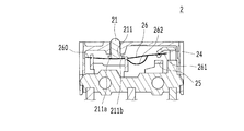
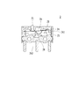
- FIG. 2 is a schematic cross-sectional view illustrating an example of a cross section of the switch described in the present application.
- FIG. 3 is a schematic external view illustrating an example of a pressing member included in the switch described in the present application.
- FIG. 3 is a schematic external view illustrating an example of a pressing member included in the switch described in the present application.
- It is a schematic external view showing an example of a movable contact piece provided in the switch described in the present application.
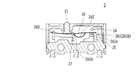
- FIG. 4 is a schematic cross-sectional view illustrating an example of the operation of the switch described in the present application.
- FIG. 4 is a schematic cross-sectional view illustrating an example of the operation of the switch described in the present application.
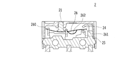
- FIG. 4 is a schematic cross-sectional view illustrating an example of the operation of the switch described in the present application.
- FIG. 4 is a schematic cross-sectional view illustrating an example of the operation of the switch described in the present application.
- FIG. 4 is a graph schematically showing an example of a relationship between a push amount of a switch and an operation load described in the present application as a dynamic system model.
- FIG. 3 is a schematic external view illustrating an example of a pressing member included in the switch described in the present application.
- FIG. 3 is a schematic external view illustrating an example of a pressing member included in the switch described in the present application.
- FIG. 2 is a schematic cross-sectional view illustrating an example of a cross section of the switch described in the present application. It is a schematic perspective view which shows an example of the buffer member with which the switch of this application is provided. It is a schematic perspective view which shows an example of the buffer member with which the switch of this application is provided.
- the operating device described in the present application is used, for example, as an operating device such as a mouse used for operating a personal computer (hereinafter, referred to as a personal computer).
- the switch described in the present application is used as a microswitch in devices such as various electronic devices including an operation device.
- the operating device 1 and the switch 2 illustrated in the drawings will be described with reference to the drawings.
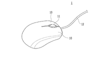
- FIG. 1 is a schematic perspective view showing an example of the appearance of the operating device 1 described in the present application.
- FIG. 1 shows an example in which the operating device 1 described in the present application is applied to a mouse used for operating an electronic device such as a personal computer.
- the operating device 1 includes a pressing operation unit 10 such as a mouse button that receives an operation of pressing with an operator's finger, and a rotating operation unit 11 such as a mouse wheel that receives an operation of rotating with the finger of the operator. .
- the rotation operation unit 11 is configured to receive not only a rotation operation but also a pressing operation, and also functions as the pressing operation unit 10.
- the operating device 1 is connected to a signal line 12 that outputs an electric signal to an external device such as a personal computer.
- the operation device 1 is not limited to wired communication using the signal line 12, and can output an electric signal by various communication methods such as wireless communication.
- a switch 2 described later is accommodated in the operation device 1 for each of the press operation units 10 and the rotation operation units 11.
- the operation of the press operation unit 10 is performed.
- An internal part presses the corresponding switch 2.
- the switch 2 outputs a signal based on the pressing state from the signal line 12 to an external electronic device such as a personal computer.
- the operating device 1 described in the present application includes a pressing operation unit 10 that receives a pressing operation from the outside, a turning operation unit 11 that receives an operation such as a turning operation, and a switch 2 inside.
- the operating device 1 transmits the pressing operation received by the pressing operation unit 10 and / or the rotating operation unit 11 to the switch 2 as an external pressing, and outputs a signal based on the operation of the switch 2 to an external electronic device. I do.
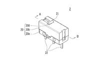
- FIG. 2 is a schematic perspective view showing an example of the appearance of the switch 2 described in the present application.
- the direction of the switch 2 is such that the left front side is forward, the right rear side is rearward, the upper side is up, the lower side is down, the left rear side is left, and the right front side is right, as viewed in FIG. Although it is expressed, it is a direction for convenience of explanation, and does not limit the mounting direction of the switch 2.
- the switch 2 is housed as a microswitch inside the electronic device such as the operating device 1 and receives a pressing operation received by a part such as the pressing operation unit 10 of the operating device 1 as an external pressing.
- the switch 2 includes a substantially rectangular parallelepiped housing 20.
- the housing 20 is formed by a lower base 20a and an upper cover 20b.
- a rectangular insertion hole 200 through which the pressing member 21 is inserted is formed on the upper surface of the housing 20 at a position on the left side from the center when viewed from the front.
- the pressing member 21 inserted into the insertion hole 200 is a member that moves up and down by being pressed from the outside of the housing 20, and the upper end of the pressing member 21 protrudes from the upper surface of the housing 20.
- the pressing operation from the outside received by the operating device 1 is transmitted to the pressing member 21 as the pressing from the outside of the housing 20.
- the pressing member 21 moves downward in response to an external pressure, and moves upward when the external pressure is released.
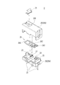
- FIG. 3 is a schematic exploded perspective view showing an example of the switch 2 described in the present application.
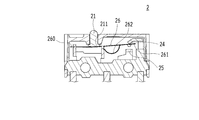
- FIG. 4 is a schematic sectional view showing an example of a section of the switch 2 described in the present application.
- FIG. 4 shows a cross section cut along a vertical plane including the line AB shown in FIG. 2 in the direction of the arrow.
- An area as a contact chamber for accommodating a contact mechanism for opening and closing an electric circuit is secured in the housing 20 of the switch 2.
- An insertion hole 200 penetrating from the outside of the housing 20 is formed on the upper surface of the contact chamber, and the pressing member 21 is inserted into the insertion hole 200.
- the contact mechanism accommodated in the contact chamber will be described.
- members such as a common contact terminal 23, a first contact terminal 24, a second contact terminal 25, and a movable contact piece 26 are provided as a contact mechanism.
- the common contact terminal 23 is disposed on the left side in the contact chamber, and is electrically connected to the connection terminal portion 22 on the left side.
- the first contact terminal 24 is disposed on the upper right side in the contact chamber, and is electrically connected to the right connection terminal portion 22.
- the second contact terminal 25 is disposed on the lower right side in the contact chamber, and is electrically connected to the central connection terminal portion 22.
- the movable contact piece 26 is a plate-shaped conductive metal member extending in the left-right direction in the contact chamber.
- the left end side of the movable contact piece 26 is a fixed end that is locked to the common contact terminal 23 and functions as a swing fulcrum 260.
- the right end side of the movable contact piece 26 is a free end that moves between the first contact terminal 24 and the second contact terminal 25, and is a movable contact 261.
- the movable contact piece 26 is formed with an urging portion 262 that functions as a return spring whose center is punched out and bent in an arc shape, and a tip of the urging portion 262 is formed near the center in the contact chamber.
- the locking plate 27 is locked.
- the urging portion 262 generates a reaction force against the pressing of the pressing member 21.
- the pressing member 21 receives an external pressure and moves downward to press the movable contact piece 26.
- the right end which is the free end of the movable contact piece 26, is lowered, and the movable contact 261 contacts the second contact terminal 25.
- the left connection terminal portion 22 connected to the common contact terminal 23 and the center connection terminal portion 22 connected to the second contact terminal 25 are brought into conduction.
- the movable contact piece 26 When the pressing of the pressing member 21 is released, the movable contact piece 26 is urged upward by the reaction force of the urging portion 262. When the movable contact piece 26 is urged upward, the pressing member 21 moves upward. Further, when the movable contact piece 26 is urged upward by the urging portion 262, the movable contact 261 located on the right end side of the movable contact piece 26 rises, and comes into contact with the first contact terminal 24. Thus, the left connection terminal portion 22 connected to the common contact terminal 23 and the right connection terminal portion 22 connected to the first contact terminal 24 are brought into conduction.
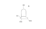
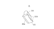
- FIG. 5A and 5B are schematic external views illustrating an example of the pressing member 21 included in the switch 2 described in the present application.
- FIG. 5A is a schematic front view
- FIG. 5B is a schematic perspective view viewed from obliquely below.
- the pressing member 21 includes an upper pressed protrusion 210 and a lower pressing plate 211.
- the pressed protrusion 210 of the pressing member 21 has a substantially rectangular parallelepiped shape, and an upper end is formed as a curved surface having a semicircular shape in a front view.
- the pressed projection 210 has an upper portion protruding from the insertion hole 200 of the housing 20 and receives external pressure.
- the pressing plate 211 has a substantially rectangular shape in a plan view, and the lower surface facing the movable contact piece 26 is formed in a substantially planar shape.
- the left end of the lower surface of the pressing plate 211 is formed so as to be inclined upward in a tapered shape, and a first ridgeline 211a serving as a boundary between the flat portion and the tapered portion extends linearly forward and backward.
- the portion that comes into contact with the movable contact piece 26 is a portion that slightly projects rightward at the front end and the rear end.
- the pressing member 21 contacts the movable contact piece 26 at a plurality of locations including at least the first ridgeline 211a and the second ridgeline 211b.
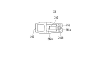
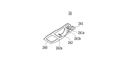
- FIG. 6A and 6B are schematic external views showing an example of the movable contact piece 26 included in the switch 2 described in the present application.
- FIG. 6A is a schematic plan view
- FIG. 6B is a schematic perspective view as viewed obliquely from below.
- the movable contact piece 26 is a flexible member formed of a thin metal plate.
- the movable contact piece 26 has a substantially rectangular shape in a plan view, and the right end, which is a free end, is formed as a movable contact 261, and a contact projection 261 a is provided on the lower surface of the movable contact 261.
- the contact protrusion 261a is provided on the lower surface side of the elastic piece 261b punched out so as to extend from the right end to the left.
- the elastic piece 261b has a substantially rectangular shape, and one side on the right side is continuous with the left end of the movable contact piece 26. Since the elastic piece 261b swings around the continuous part as a fulcrum, it has an elastic shape having elasticity. .
- the aforementioned urging portion 262 is formed on the left side of the elastic piece 261b.
- the biasing portion 262 is formed by bending a portion punched out so as to extend in a belt shape from the right side to the left side so as to function as a return spring into an arc shape with a downward convex.
- the tip of the urging portion 262 is a locking portion 262a that is locked by a locking plate 27 protruding from the base 20a of the housing 20, and the pressing portion 262 is locked by the locking plate 27.
- the movable contact 261 on the right side swings with the locked portion 262a as the swing axis.
- 7 to 10 are schematic sectional views showing an example of the operation of the switch 2 described in the present application. 7 to 10 show cross sections taken along a vertical plane including the line AB shown in FIG. 2 from a front view.
- FIG. 7 shows a state where the pressing member 21 is not pressed from the outside.
- the lower end of the pressing member 21 is a portion between the swing fulcrum 260 at which the left end of the movable contact piece 26 is locked and the position at which the locking portion 262a at the tip of the urging portion 262 of the movable contact piece 26 is locked.
- the lower surface of the lower pressing plate 211 is in contact with the movable contact piece 26.
- the movable contact piece 26 is moved upward by a reaction force against the pressing of the pressing member 21 by the urging portion 262 located between the contact portion receiving the pressing of the pressing member 21 and the movable contact 261.
- the free end formed as the movable contact 261 is in contact with the first contact terminal 24 disposed on the upper right side in the contact chamber.
- FIG. 8 shows a state where the pressing member 21 has been moved downward by receiving an external pressure from the state shown in FIG.
- the pressing plate 211 located below the pressing member 21 presses the movable contact piece 26 downward.
- the pressing member 21 comes into contact with the movable contact piece 26 at two points of the first ridge line 211a and the second ridge line 211b of the pressing plate 211.
- the entire movable contact piece 26 is pressed by the pressing member 21 and tends to move downward with the swing fulcrum 260 as the swing axis.
- the movable contact piece 26 is pushed upward by a reaction force against the pressing of the pressing member 21 by the urging portion 262 located between the contact portion receiving the pressing of the pressing member 21 and the movable contact 261.
- the movable contact 261 maintains a state of being in contact with the first contact terminal 24 provided on the upper right side in the contact chamber. Therefore, the movable contact piece 26 receives the pressure from the pressing member 21 and bends downward to be bent.
- FIG. 9 shows a state in which the pressing member 21 has been moved downward by further pressing from the outside from the state shown in FIG.
- the entire movable contact piece 26 is pressed by the pressing member 21 and attempts to move downward with the swing fulcrum 260 as the swing axis. Since the urging portion 262 of the movable contact piece 26 swings downward about the locking portion 262a locked on the locking plate 27 as a swing axis, the entire movable contact piece 26 is inverted. Oscillate with the fulcrum 260 as the oscillating axis. Therefore, the contact protrusion 261a of the movable contact 261 contacts the second contact terminal 25 provided as a fixed contact on the lower right side in the contact chamber.
- the left connection terminal portion 22 connected to the common contact terminal 23 and the center connection terminal portion 22 connected to the second contact terminal 25 become conductive.
- the contact protrusion 261a of the movable contact 261 collides with the second contact terminal 25 with the force of inversion of the movable contact piece 26, and thus involves an impact.
- the contact protrusion 261a is formed on the elastic piece 261b having an elastic shape, the impact with the second contact terminal 25 is reduced, and the sound generated at that time is suppressed.
- FIG. 10 shows a state in which the pressing member 21 has been further moved from the state shown in FIG. 9 to the lowest point of the movable range by receiving further pressing from the outside.
- the entire movable contact piece 26 is pressed by the pressing member 21 and tends to move downward with the swing fulcrum 260 as the swing axis. Accordingly, the movable contact piece 26 is bent so as to be bent downward while being supported by the swing fulcrum 260 and the movable contact 261 at both ends.
- the movable contact piece 26 When the pressing of the pressing member 21 is released, the movable contact piece 26 is urged upward by the reaction force of the urging portion 262. When the movable contact piece 26 is urged upward, the pressing member 21 moves upward. When the movable contact piece 26 is urged upward by the urging portion 262, the movable contact 261, which is a free end of the movable contact piece 26, rises and comes into contact with the first contact terminal 24. That is, the state illustrated in FIG. 7 is obtained.
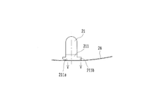
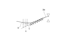
- FIG. 11A is an explanatory diagram schematically illustrating an example of a dynamic system model related to the pressing members 21 and 21x and the movable contact pieces 26 and 26x included in the switch 2 described in the present application.
- FIG. 11B is a diagram for comparison, and is an explanatory diagram schematically illustrating an example of a dynamic system model related to the pressing member 21x and the movable contact piece 26x included in the conventional switch 2x.
- 11A and 11B show the pressing members 21 and 21x and the movable contact pieces 26 and 26x from a front view.
- the dashed line indicates the center of the force that presses the movable contact pieces 26 and 26x in response to external pressure
- the arrows indicate that the pressing members 21 and 21x move the movable contact pieces 26 and 26x. Shows the force applied to
- the lower surface of the pressing plate 211 formed below the pressing member 21 provided in the switch 2 of the present application is formed in a substantially planar shape. Since the movable contact piece 26 is pressed by the pressing member 21 to bend and bend downward, the pressing member 21 comes into contact with the movable contact piece 26 at two contact portions of the first ridge line 211a and the second ridge line 211b. . That is, the pressing member 21 receives the external pressure and presses the movable contact piece 26 with respect to the center of the force that presses the movable contact piece 26.
- the pressing member 21 presses the movable contact piece 26 at two contact sites as indicated by arrows in the drawing.
- the lower part of the pressing member 21x is formed in an arc shape that is convex downward, and the pressing member 21x substantially coincides with the center of the pressing force.
- the movable contact piece 26x is brought into contact with the contact piece 26x at one contact point, and the movable contact piece 26x is pressed at one contact point as shown by the arrow in the figure.
- FIG. 12 is an explanatory diagram schematically showing an example of a dynamic model of a conventional switch 2x.
- 13A and 13B are explanatory diagrams schematically showing an example of the relationship between the load of the conventional switch 2x and the movable contact piece 26x as a dynamic system model.
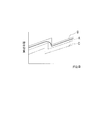
- FIG. 14 is a graph schematically showing the relationship between the pressing amount and the operating load of the conventional switch 2x as a dynamic system model.
- FIG. 12 shows a cross section obtained by cutting the switch 2x in a vertical plane from a front view, and shows the movement of the movable contact piece 26x intermittently.
- FIG. 13A schematically illustrates the relationship between the load and the deflection of the support beam at both ends
- FIG. 13B schematically illustrates the timing of the reversing operation.
- FIG. 14 shows the pushing amount (operation stroke) of the pressing member 21x when the pressing member 21x of the switch 2x is pushed downward on the horizontal axis, and the operation load received by the pressing member 21x when pushed on the vertical axis. This shows the relationship.
- the pressing member 21x comes into contact with the movable contact piece 26x at one contact portion in the pressing process.
- the dashed white arrow indicates the pressing force when the pressing member 21x contacts the movable contact piece 26x at the position A shown in FIG. 14, the broken line indicates the relationship between the pushing amount and the operating load when the pressing member 21x contacts the movable contact piece 26x at the position A shown in FIG.
- FIGS. 12, 13A and 13B and the dashed-dotted line shown in FIG. 14 indicate that the pressing member 21x is movable at a position B which is closer to the swing fulcrum 260x than the position A (left side in the figure). The pressing force and the relationship when assuming that it contacts the contact piece 26x are shown.
- the dashed-dotted white arrows shown in FIGS. 12, 13A and 13B and the dashed-dotted line shown in FIG. 14 indicate the position C on the movable contact 261x side (right side in the drawing) from the position A, and the pressing member 21x The pressing force and the relationship when it is assumed that the movable contact piece 26x comes into contact are shown.
- FIG. 13A shows the relationship between the pressing force on the movable contact piece 26x and the movable contact piece 26x, assuming a support beam at both ends. Assuming a support beam at both ends, the force required to generate the same deflection is greatest at position B near the swing fulcrum 260x, and then decreases in the order of position A and position C.
- FIG. 13B shows the timing of the reversing operation, in which the position B near the swing fulcrum 260x is the latest, and then the position A and the position C are earlier. From these relationships, a graph shown in FIG. 14 is obtained. In FIG. 14, the point at which the operation load suddenly falls is the position where the movable contact piece 26x is inverted. As shown in FIG. 14, at the reversing position, the load increases in the order closer to the swing fulcrum 260x, and the timing of the reversing operation with respect to the pushing amount is delayed. Then, a loud sound is generated during the inversion operation.
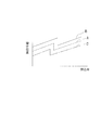
- FIG. 15 is an explanatory diagram schematically showing an example of the dynamic system model of the switch 2 described in the present application.
- FIG. 16 is a schematic diagram showing an example of the relationship between the pushing amount and the operation load of the switch 2 described in the present application as a dynamic system model. It is a graph shown typically.
- the pressing member 21 included in the switch 2 described in the present application has a flat lower surface, and thus contacts the movable contact piece 26 at two contact sites during the pressing process.
- the outline arrows indicated by the dashed line, the solid line, and the dashed line indicate the pressing force when the movable contact piece 26 comes into contact with the positions A, B, and C illustrated in FIG. 12. Shown for comparison.
- FIG. 15 is an explanatory diagram schematically showing an example of the dynamic system model of the switch 2 described in the present application.
- FIG. 16 is a schematic diagram showing an example of the relationship between the pushing amount and the operation load of the switch 2 described in the present application as a dynamic system model. It is a graph
- a thick line indicates the relationship between the pushing amount and the operation load of the switch 2 described in the present application
- a broken line, a solid line, and a dashed line indicate the relationship between the pushing amount and the operation load at the positions A, B, and C. Shown for comparison.
- the pressing member 21 receives the pressing from the outside, contacts the movable contact piece 26 at the first ridge line 211a and the second ridge line 211b, and presses the movable contact piece 26.
- the movable contact piece 26 pressed by the pressing member 21 maintains the state of being in contact with the first ridge line 211a and the second ridge line 211b while bending, but the reaction force and the ratio thereof to the first ridge line 211a and the second ridge line 211b are , And changes according to the pushing amount.
- the relationship between the pushing amount and the operation load does not change abruptly as in the case of pressing at one contact portion of the position A, the position B, and the position C, but changes like a thick line shown in FIG. . That is, when the movable contact piece 26 is inverted, the switching time from the state in which the movable contact piece 26 is in contact with the first contact terminal 24 to the time when the movable contact piece 26 collides with the second contact terminal 25 becomes longer, and the contact protrusion 261a of the movable contact 261 becomes second contact. The speed of the collision with the terminal 25 is reduced.
- the shock at the time of the collision is alleviated, and a noise generated by the collision of the contact protrusion 261a, that is, a so-called click sound is reduced, so that a silent effect is obtained.
- the switch 2 described in the present application can suppress the generation of sound as compared with the case where the pressing member 21 contacts the movable contact piece 26 at a plurality of locations, as compared with the case where the pressing member 21 contacts the movable contact piece 26 at one location. It is.
- the shape of the pressing member 21 is not limited to the above-described embodiment, but may be changed to various shapes as long as the pressing member 21 comes into contact with the movable contact piece 26 at a plurality of locations during pressing.
- 17A and 17B are schematic external views showing an example of the pressing member 21 provided in the switch 2 described in the present application.
- FIG. 17A is a schematic front view
- FIG. 17B is a schematic perspective view as viewed obliquely from below.
- portions corresponding to the first ridge line 211a and the second ridge line 211b protrude downward, forming a first contact protrusion 211c and a second contact protrusion 211d.
- the second embodiment is a mode in which the generation of sound is suppressed by using the buffer member in the first embodiment, and the quietness is improved.
- the same components as those in the first embodiment are denoted by the same reference numerals as those in the first embodiment, and the first embodiment is referred to, and the description is omitted.
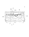
- FIG. 18 is a schematic sectional view showing an example of a section of the switch 2 described in the present application.
- FIG. 18 shows a cross section of the switch 2 taken along a vertical plane, as viewed from the front.
- FIGS. 19A and 19B are schematic perspective views showing an example of a buffer member provided in the switch 2 described in the present application.
- FIG. 19A shows the contact buffer member 28.
- the contact cushioning member 28 is a member formed by molding an elastic material such as polyurethane rubber, and is formed by combining the upper member 280 and the lower member 281.
- the upper member 280 has a substantially rectangular parallelepiped shape, and the right end side in contact with the inner wall surface of the housing 20 extends downward and is fixed.
- a notch for fitting the first contact terminal 24 is formed in the portion to be fixed.
- a lower member 281 having a U-shape in plan view is affixed to the lower surface on the left end side of the upper member 280.
- the contact buffer member 28 formed by the upper member 280 and the lower member 281 covers the first contact terminal 24, and the movable contact 261, which is a free end of the movable contact piece 26, passes through the first contact terminal 24. Indirectly or directly in contact with the lower member 281 of the contact buffer member 28.
- the movable contact piece 26 collides with the first contact terminal 24 when the pressing of the pressing member 21 is released and moves up.
- the first contact terminal 24 is covered with a contact buffer member 28, and the movable contact piece 26 is indirectly or directly in contact with the contact buffer member 28 via the first contact terminal 24. . Therefore, the contact cushioning member 28 reduces the impact at the time of collision and suppresses the generation of sound due to the collision.
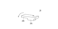
- FIG. 19B shows the urging portion buffer member 29.
- the biasing portion buffer member 29 is a member formed by molding an elastic material such as polyurethane rubber.
- the urging portion buffer member 29 has a shape in which a substantially rectangular parallelepiped base portion 291 is formed on the lower surface of a plate-like body 290 having a substantially rectangular shape in a plan view. A notch is formed so that the second contact terminal 25 is fitted.
- the plate-shaped body 290 is in contact with the lower surface of the urging portion 262 on the upper surface on the left end side.
- the base portion 291 is formed on the right side of the plate-like body 290, the left end side of the plate-like body 290 is bent as shown by an arrow in the figure due to the swing of the urging portion 262, and absorbs an impact. I do. Thereby, the shock generated when the urging portion 262 swings is absorbed.
- the second contact terminal 25 is fitted to the plate-like body 290, the impact when the movable contact 261 of the movable contact piece 26 collides with the second contact terminal 25 is reduced, and the sound due to the collision is generated. Suppress.
- the switch 2 has various shapes such as the shape of the pressing member 21 and the shape of the movable contact piece 26 near the movable contact 261.
- the cushioning members such as the contact cushioning member 28 and the urging portion cushioning member 29 provide excellent effects such as suppressing the generation of sound accompanying the operation of the movable contact piece 26.
- the pressing member 21 that comes into contact with the movable contact piece 26 at two contact sites has been exemplified.
- the present invention is not limited to this, and the pressing member 21 may have a shape that contacts the movable contact piece 26 at three or more contact sites. It can be developed in various forms such as forming the pressing member 21.
- a mouse is exemplified as the operation device 1 including the switch 2.
- the present invention is not limited to this, and various devices such as a keyboard and various push buttons used for operation are applied as the operation device 1. Can be developed in various forms.
Landscapes
- Push-Button Switches (AREA)
Abstract
【課題】静音効果に優れたスイッチ及び操作装置を提供する。 【解決手段】スイッチ2は、固定接点25と、可撓性を有し、一端側が揺動支点260、他端側が可動接点261となる可動接触片26と、外部からの押圧を受けて、可動接触片26の揺動支点260及び可動接点261の間を押圧する押圧部材21とを備えており、可動接触片26は、押圧部材21に押圧されて揺動し、可動接点261が固定接点25と接触する。押圧部材21は、可動接触片26に複数の接触部位で接触して、可動接触片26を押圧する。
Description
本発明は、固定接点と、可動接点を有する可動接触片と、外部からの押圧を受けて可動接触片を押圧する押圧部材とを備え、押圧部材の押圧により可動接点が固定接点と接触するスイッチ、及びそのようなスイッチを用いた操作装置に関する。
電子機器等の装置に用いられるスイッチが普及している。例えば、特許文献1には、スライド式のスイッチとスナップアクション式のスイッチとの両方の特性を備え、操作ボタンを押し込むことで、インナーアクチュエータを押圧し、可動接点を常開接点に接触させるスイッチが開示されている。特許文献1に開示されたスイッチは、可動接点と常開接点とが摺動接触する構造となっているため、衝突音が発生することなく、静音性を向上させている。
特許文献1にも開示されているように、静音性に優れたスイッチに対する要求があり、特許文献1に開示されている構造以外にも、静音効果に優れた構造を備えるスイッチが求められている。
本発明は斯かる事情に鑑みてなされたものであり、押圧部材は、可動接触片に複数の接触部位で接触することにより、音の発生を抑制するスイッチの提供を目的とする。
また、本発明は、そのようなスイッチを用いた操作装置の提供を他の目的とする。
上記課題を解決するため、本願記載のスイッチは、固定接点と、可撓性を有し、一端側が揺動支点、他端側が可動接点となる可動接触片と、外部からの押圧を受けて、前記可動接触片の揺動支点及び可動接点の間を押圧する押圧部材とを備え、前記可動接触片は、前記押圧部材に押圧されて揺動し、前記可動接点が前記固定接点と接触するスイッチであって、前記押圧部材は、前記可動接触片に複数の接触部位で接触して、前記可動接触片を押圧することを特徴とする。
また、前記スイッチにおいて、前記押圧部材は、外部からの押圧を受けて前記可動接触片を押圧する力の中心に対し、揺動支点側及び可動接点側に前記接触部位を有することを特徴とする。
また、前記スイッチにおいて、前記可動接触片の可動接点は、他端部に弾性形状で形成されていることを特徴とする。
また、前記スイッチにおいて、前記可動接触片は、前記押圧部材の押圧を受ける前記接触部位及び前記可動接点の間に、前記押圧部材の押圧に抗する反力を生じさせる付勢部が形成されていることを特徴とする。
また、前記スイッチにおいて、前記可動接触片は、前記押圧部材の押圧を受けて撓み、更なる押圧を受けて、前記付勢部が係止された係止部を揺動軸として前記可動接点側が揺動することにより、前記固定接点と接触するように形成されていることを特徴とする。
また、前記スイッチにおいて、前記付勢部に当接するように配設された付勢部用緩衝部材を備えることを特徴とする。
また、前記スイッチにおいて、前記押圧部材が外部から押圧されていない場合に、前記可動接触片の他端側が当接するように配設された接点用緩衝部材を備えることを特徴とする。
更に、本願記載の操作装置は、外部からの押下操作を受け付ける押下操作部と、前記押下操作部が受け付けた押下操作を外部からの押圧として伝達される前記スイッチとを備え、前記スイッチが備える前記可動接点の動作に基づく信号を出力することを特徴とする。
本願記載のスイッチ及び操作装置は、押圧部材の押圧に基づく音の発生を抑制することが可能である。
本発明に係るスイッチ及び操作装置は、可撓性を有し、一端側が揺動支点、他端側が可動接点となる可動接触片に対し、複数の接触部位で接触する押圧部材により押圧する。これにより、押圧の際に生じる音の発生を抑制し、静音性を向上させることが可能である等、優れた効果を奏する。
<適用例>
本願記載の操作装置は、例えば、パーソナルコンピュータ(以下、パソコンという)の操作に用いられるマウス等の操作装置として用いられる。また、本願記載のスイッチは、操作装置を含む様々な電子機器等の装置にマイクロスイッチとして用いられる。以下では、図面を参照しながら図面に例示された操作装置1及びスイッチ2について説明する。
本願記載の操作装置は、例えば、パーソナルコンピュータ(以下、パソコンという)の操作に用いられるマウス等の操作装置として用いられる。また、本願記載のスイッチは、操作装置を含む様々な電子機器等の装置にマイクロスイッチとして用いられる。以下では、図面を参照しながら図面に例示された操作装置1及びスイッチ2について説明する。
<第1実施形態>
<操作装置1>
まず、操作装置1について説明する。図1は、本願記載の操作装置1の外観の一例を示す概略斜視図である。図1は、本願記載の操作装置1を、パソコン等の電子機器の操作に用いるマウスに適用した例を示している。操作装置1は、操作者の指にて押下する操作を受け付けるマウスボタン等の押下操作部10、操作者の指にて回動する操作を受け付けるマウスホイール等の回動操作部11を備えている。なお、回動操作部11は、回動操作だけでなく、押下操作も受け付けるように構成されており、押下操作部10としても機能する。また、操作装置1には、パソコン等の外部の機器に電気信号を出力する信号線12が接続されている。なお、操作装置1は、信号線12を用いた有線通信に限らず、無線通信等の様々な通信方法により電気信号を出力することが可能である。
<操作装置1>
まず、操作装置1について説明する。図1は、本願記載の操作装置1の外観の一例を示す概略斜視図である。図1は、本願記載の操作装置1を、パソコン等の電子機器の操作に用いるマウスに適用した例を示している。操作装置1は、操作者の指にて押下する操作を受け付けるマウスボタン等の押下操作部10、操作者の指にて回動する操作を受け付けるマウスホイール等の回動操作部11を備えている。なお、回動操作部11は、回動操作だけでなく、押下操作も受け付けるように構成されており、押下操作部10としても機能する。また、操作装置1には、パソコン等の外部の機器に電気信号を出力する信号線12が接続されている。なお、操作装置1は、信号線12を用いた有線通信に限らず、無線通信等の様々な通信方法により電気信号を出力することが可能である。
操作装置1の内部には、各押下操作部10及び回動操作部11毎に、後述するスイッチ2が収容されており、押下操作部10に対して押下操作をした場合、押下操作部10の内部の部位が、対応するスイッチ2を押圧する。スイッチ2は、押圧状況に基づく信号を信号線12から外部のパソコン等の電子機器へ出力する。
即ち、本願記載の操作装置1は、外部からの押下操作を受け付ける押下操作部10と、回動操作等の操作を受け付ける回動操作部11とを備え、更に内部にスイッチ2を備えている。そして、操作装置1は、押下操作部10及び/又は回動操作部11が受け付けた押下操作を外部からの押圧としてスイッチ2に伝達し、スイッチ2の動作に基づく信号を外部の電子機器へ出力する。
<スイッチ2>
次に、本願記載のスイッチ2について説明する。図2は、本願記載のスイッチ2の外観の一例を示す概略斜視図である。なお、本願明細書において、スイッチ2の方向については、図2に向かって左手前側を前、右奥側を後、上方を上、下方を下、左奥側を左、そして右手前側を右として表現するが、説明の便宜上の方向であり、スイッチ2の組込方向を限定するものではない。前述のようにスイッチ2は、操作装置1等の電子機器の内部にマイクロスイッチとして収容され、操作装置1の押下操作部10等の部位が受け付けた押下操作を外部からの押圧として受け付ける。
次に、本願記載のスイッチ2について説明する。図2は、本願記載のスイッチ2の外観の一例を示す概略斜視図である。なお、本願明細書において、スイッチ2の方向については、図2に向かって左手前側を前、右奥側を後、上方を上、下方を下、左奥側を左、そして右手前側を右として表現するが、説明の便宜上の方向であり、スイッチ2の組込方向を限定するものではない。前述のようにスイッチ2は、操作装置1等の電子機器の内部にマイクロスイッチとして収容され、操作装置1の押下操作部10等の部位が受け付けた押下操作を外部からの押圧として受け付ける。
スイッチ2は、略直方体状をなす筐体20を備えている。筐体20は、下部のベース20a及び上部のカバー20bにて形成されている。筐体20の上面には、正面視で中央から左寄りの位置に、押圧部材21が挿通される長方形状の挿通孔200が開設されている。挿通孔200に挿通されている押圧部材21は、筐体20の外部からの押圧を受けて上下に移動する部材であり、筐体20の上面からは、押圧部材21の上端が突出している。更に、筐体20の下側からは、他の電気部材を接続可能な金属片である3本の接続端子部22が突出している。
このように形成されたスイッチ2では、操作装置1が受け付けた外部からの押下操作が、筐体20の外部からの押圧として押圧部材21に伝達される。押圧部材21は、外部からの押圧を受けて下方へ移動し、外部からの押圧が解除されると上方へ移動する。
次にスイッチ2の内部構造について説明する。図3は、本願記載のスイッチ2の一例を示す概略分解斜視図である。図4は、本願記載のスイッチ2の断面の一例を示す概略断面図である。図4は、図2に示すA-B線分を含む垂直面で切断した断面を矢印方向に向かって示している。
スイッチ2の筐体20内には、電気回路を開閉する接点機構を収容する接点室としての領域が確保されている。接点室の上面には、筐体20の外側から貫通する挿通孔200が開設されており、挿通孔200には、押圧部材21が挿通されている。
接点室内に収容された接点機構について説明する。接点室内には、接点機構として、共通接点端子23、第1接点端子24、第2接点端子25、可動接触片26等の部材が配設されている。共通接点端子23は、接点室内の左側に配設されており、左側の接続端子部22と電気的に接続されている。第1接点端子24は、接点室内の右上側に配設されており、右側の接続端子部22と電気的に接続されている。第2接点端子25は、接点室内の右下側に配設されており、中央の接続端子部22と電気的に接続されている。
可動接触片26は、接点室内において、左右方向に延びる板状の導電性金属部材である。可動接触片26の左端側は、共通接点端子23に係止され揺動支点260として機能する固定端となっている。可動接触片26の右端側は、第1接点端子24及び第2接点端子25の間で移動する自由端であり、可動接点261となっている。なお、可動接触片26には、中央付近が打ち抜かれ円弧状に折り曲げられた復帰バネとして機能する付勢部262が形成されており、付勢部262の先端は、接点室内の中央近傍に形成された係止板27に係止されている。付勢部262は、押圧部材21の押圧に抗する反力を生じさせる。
このように構成された接点機構は、押圧部材21が外部からの押圧を受けて下方へ移動し、可動接触片26を押下する。可動接触片26が押下されることにより、可動接触片26の自由端である右端側が下がり、可動接点261が第2接点端子25に接触する。これにより、共通接点端子23に接続された左側の接続端子部22と、第2接点端子25に接続された中央の接続端子部22とが導通状態となる。
押圧部材21の押圧が解除されると、付勢部262の反力により可動接触片26は上方へ付勢される。可動接触片26が上方へ付勢されることにより、押圧部材21が上方へ移動する。また、付勢部262により可動接触片26が上方へ付勢されることにより、可動接触片26の右端側に位置する可動接点261が上がり、第1接点端子24に接触する。これにより、共通接点端子23に接続された左側の接続端子部22と、第1接点端子24に接続された右側の接続端子部22とが導通状態となる。
押圧部材21及び可動接触片26の形状について更に説明する。図5A及び図5Bは、本願記載のスイッチ2が備える押圧部材21の一例を示す概略外観図である。図5Aは、概略正面図であり、図5Bは、斜め下からの視点で示す概略斜視図である。押圧部材21は、上部側の被押圧突起210と、下部側の押圧板211とにより構成されている。押圧部材21の被押圧突起210は、略直方体状をなし、上端が正面視半円形状の曲面として形成されている。被押圧突起210は、上部が筐体20の挿通孔200から突出し、外部からの押圧を受け付ける。押圧板211は、平面視略長方形状をなしており、可動接触片26に対向する下面は、略平面状に形成されている。押圧板211の下面の左端は、テーパー状に上方へ傾斜するように形成されており、平面部分とテーパー部分との境界となる第1稜線211aは、前後に直線状に延びている。押圧板211の下面の右端側の第2稜線211bにおいて、可動接触片26と接する部位は、前端及び後端の若干右方向へ突出した部位である。押圧部材21は、可動接触片26を押圧する過程において、少なくとも第1稜線211a及び第2稜線211bを含む複数箇所で可動接触片26に接する。
図6A及び図6Bは、本願記載のスイッチ2が備える可動接触片26の一例を示す概略外観図である。図6Aは、概略平面図であり、図6Bは、斜め下からの視点で示す概略斜視図である。可動接触片26は、薄い金属板から形成された可撓性を有する部材である。可動接触片26は、平面視略長方形状をなし、自由端となる右端部側は可動接点261として形成されており、可動接点261の下面側に接点突起261aが突設されている。接点突起261aは、右端部から左側へ延びるように打ち抜かれた弾性片261bの下面側に突設されている。弾性片261bは、略長方形状をなし、右側の一辺が可動接触片26の左端部と連続しており、連続している部位を支点として揺動するため、弾性を有する弾性形状となっている。弾性片261bの左側には、前述の付勢部262が形成されている。付勢部262は、右側から左側へ帯状に延びるように打ち抜かれた部分を、復帰バネとして機能するように下方が凸の円弧状に折り曲げて形成されている。付勢部262の先端は、筐体20のベース20aに突設された係止板27に係止される係止部262aとなっており、付勢部262は、係止板27に係止された係止部262aを揺動軸として右側となる可動接点261部側が揺動する。
<スイッチ2の動作>
以上のように構成された本願記載のスイッチ2の動作について説明する。図7乃至図10は、本願記載のスイッチ2の動作の一例を示す概略断面図である。図7乃至図10は、図2に示すA-B線分を含む垂直面で切断した断面を正面からの視点で示している。
以上のように構成された本願記載のスイッチ2の動作について説明する。図7乃至図10は、本願記載のスイッチ2の動作の一例を示す概略断面図である。図7乃至図10は、図2に示すA-B線分を含む垂直面で切断した断面を正面からの視点で示している。
図7は、押圧部材21が外部から押圧を受けていない状態を示している。押圧部材21の下端は、可動接触片26の左端が係止された揺動支点260と、可動接触片26の付勢部262先端の係止部262aが係止された位置との間の部位に対し、下部の押圧板211の下面で可動接触片26に接している。図7に示す状態において、可動接触片26は、押圧部材21の押圧を受ける接触部位及び可動接点261の間に位置する付勢部262により、押圧部材21の押圧に抗する反力にて上方へ押し上げられるため、可動接点261として形成された自由端側は、接点室内の右上側に配設された第1接点端子24に接触している。
図8は、図7に示す状態から、押圧部材21が外部からの押圧を受けて下方へ移動した状態を示している。押圧部材21が下方へ移動することにより、押圧部材21の下部に位置する押圧板211が可動接触片26を下方へ押圧する。押圧部材21は、可動接触片26に対し、押圧板211の第1稜線211a及び第2稜線211bの2点で可動接触片26に接する。可動接触片26全体は、押圧部材21に押圧され、揺動支点260を揺動軸として、下方へ移動しようとする。しかしながら、可動接触片26は、押圧部材21の押圧を受ける接触部位及び可動接点261の間に位置する付勢部262により、押圧部材21の押圧に抗する反力にて上方へ押し上げられるため、可動接点261は、接点室内の右上側に配設された第1接点端子24に接触した状態を維持する。従って、可動接触片26は、押圧部材21からの押圧を受け、下方へ屈曲し、撓んだ状態となる。
図9は、図8に示す状態から、押圧部材21が外部から更なる押圧を受けて下方へ移動した状態を示している。押圧部材21が更に下方へ移動することにより、可動接触片26全体は、押圧部材21に押圧され、揺動支点260を揺動軸として、下方へ移動しようとする。そして、可動接触片26の付勢部262が、係止板27に係止されている係止部262aを揺動軸として下方へ揺動するため、可動接触片26全体は、反転するように、揺動支点260を揺動軸として揺動する。従って、可動接点261の接点突起261aは、接点室内の右下側に固定接点として配設された第2接点端子25に接触する。これにより、共通接点端子23に接続された左側の接続端子部22と、第2接点端子25に接続された中央の接続端子部22が導通状態となる。なお、可動接点261の接点突起261aは、可動接触片26の反転の勢いで第2接点端子25に衝突するため衝撃を伴う。しかしながら、接点突起261aは、弾性形状の弾性片261bに形成されているので、第2接点端子25との衝撃が緩和され、その際に発生する音が抑制される。
図10は、図9に示す状態から、押圧部材21が外部から更なる押圧を受けて可動域の最下点まで移動した状態を示している。押圧部材21が最下点まで移動することにより、可動接触片26全体は、押圧部材21に押圧され、揺動支点260を揺動軸として下方へ移動しようとする。従って、可動接触片26は、両端の揺動支点260及び可動接点261に支えられて下方へ撓むように屈曲する。ただし、導通状態に変化はない。
押圧部材21の押圧が解除されると、付勢部262の反力により可動接触片26は上方へ付勢される。可動接触片26が上方へ付勢されることにより、押圧部材21が上方へ移動する。また、付勢部262により可動接触片26が上方へ付勢されることにより、可動接触片26の自由端である可動接点261が上がり、第1接点端子24に接触する。即ち、図7に例示した状態となる。
次に、本願記載のスイッチ2が備える押圧部材21の形状に基づく静音効果について説明する。図11Aは、本願記載のスイッチ2が備える押圧部材21,21x及び可動接触片26,26xに関する力学系モデルの一例を模式的に示す説明図である。図11Bは、比較用の図であり、従来型のスイッチ2xが備える押圧部材21x及び可動接触片26xに関する力学系モデルの一例を模式的に示す説明図である。図11A及び図11Bは、押圧部材21,21x及び可動接触片26,26xを正面からの視点で示している。図11A及び図11Bにおいて、一点鎖線は、外部からの押圧を受けて可動接触片26,26xを押圧する力の中心を示しており、矢印は、押圧部材21,21xが可動接触片26,26xに加える力を示している。
図11Aに例示するように、本願記載のスイッチ2が備える押圧部材21の下部に形成された押圧板211の下面は、略平面状に形成されている。可動接触片26は、押圧部材21に押圧されて撓み、下方へ向けて屈曲するため、押圧部材21は、第1稜線211a及び第2稜線211bの2カ所の接触部位で可動接触片26に接する。即ち、押圧部材21は、外部からの押圧を受けて可動接触片26を押圧する力の中心に対し、揺動支点260側となる第1稜線211a側及び可動接点261側となる第2稜線211b側を接触部位として有している。そして、押圧部材21は、図中矢印で示すように2カ所の接触部位で可動接触片26を押圧する。なお、図11Bに比較用に示した従来型のスイッチ2xでは、押圧部材21xの下部は下に凸となる円弧状に形成されており、押圧部材21xは、押圧する力の中心と略一致する1カ所の接触部位で可動接触片26xに接し、図中矢印で示すように1カ所の接触部位で可動接触片26xを押圧する。
図12は、従来型のスイッチ2xの力学系モデルの一例を模式的に示す説明図である。図13A及び図13Bは、従来型のスイッチ2xの荷重と可動接触片26xとの関係の一例を力学系モデルとして模式的に示す説明図である。図14は、従来型のスイッチ2xの押込量及び操作荷重の関係を力学系モデルとして概略的に示すグラフである。図12は、スイッチ2xを垂直面で切断した断面を正面からの視点で示しており、可動接触片26xの動きを断続的に示している。図13Aは、両端支持梁に係る荷重と撓みとの関係を模式的に示しており、図13Bは、反転動作のタイミングを模式的に示している。図14は、スイッチ2xの押圧部材21xが下方へ押し込まれた場合の押圧部材21xの押込量(操作ストローク)を横軸にとり、押し込まれた場合に押圧部材21xが受ける操作荷重を縦軸にとって、その関係を示している。
図12に示すように、押圧部材21xは、下面が円弧状に形成されているため、押込過程において、1カ所の接触部位で可動接触片26xに接する。図12並びに図13A及び図13Bにおいて、破線の白抜き矢印は、図12に示した位置Aで、押圧部材21xが可動接触片26xに接する場合の押圧力を示している。また、図14において、破線は、図12に示した位置Aで、押圧部材21xが可動接触片26xに接する場合の押込量及び操作荷重の関係を示している。図12、図13A及び図13Bに示す実線の白抜き矢印、並びに図14に示す実線は、位置Aより揺動支点260x側(図に向かって左側)となる位置Bで、押圧部材21xが可動接触片26xに接すると仮定した場合での押圧力及び関係を示している。図12、図13A及び図13Bに示す一点鎖線の白抜き矢印、並びに図14に示す一点鎖線は、位置Aより可動接点261x側(図に向かって右側)となる位置Cで、押圧部材21xが可動接触片26xに接すると仮定した場合での押圧力及び関係を示している。
図13Aは、可動接触片26xに係る押圧力と可動接触片26xとの関係を、両端支持梁を想定して示している。両端支持梁を想定した場合、同じ撓みを発生させるのに必要な力は、揺動支点260xに近い位置Bが最も大きく、次いで、位置A、位置Cの順に小さくなる。図13Bは、反転動作のタイミングを示しており、揺動支点260xに近い位置Bが最も遅く、次いで、位置A、位置Cの順に早くなる。これらの関係から図14に示すグラフが得られる。図14において、操作荷重が急激に下がる点が、可動接触片26xが反転する位置となる。図14に示すように、反転位置では、揺動支点260xに近い順に荷重が大きく、また、押込量に対する反転動作のタイミングが遅くなる。そして、反転動作の際に、大きな音が発生する。
図15は、本願記載のスイッチ2の力学系モデルの一例を模式的に示す説明図であり、図16は、本願記載のスイッチ2の押込量及び操作荷重の関係の一例を力学系モデルとして概略的に示すグラフである。図15に示すように、本願記載のスイッチ2が備える押圧部材21は、下面が平面状に形成されているため、押込過程において、2カ所の接触部位で可動接触片26に接する。なお、図15中において、破線、実線及び一点鎖線で示した白抜き矢印は、図12に例示した位置A、位置B及び位置Cに対応する位置で可動接触片26に接する場合の押圧力を比較のために示している。図16において、太線は、本願記載のスイッチ2の押込量及び操作荷重の関係を示しており、破線、実線及び一点鎖線は、位置A、位置B及び位置Cにおける押込量及び操作荷重の関係を比較のために示している。
本願記載のスイッチ2では、押圧部材21は、外部からの押圧を受け、第1稜線211a及び第2稜線211bにて可動接触片26に接し、可動接触片26を押圧する。押圧部材21に押圧された可動接触片26は、撓みながらも第1稜線211a及び第2稜線211bに接した状態を維持するが、第1稜線211a及び第2稜線211bに対する反力及びその比率は、押込量に応じて変化する。従って、押込量及び操作荷重の関係は、位置A、位置B及び位置Cの1カ所の接触部位で押圧した場合のように急激に変化することはなく、図16に示す太線のように変化する。即ち、可動接触片26が反転する場合、第1接点端子24に当接している状態から第2接点端子25に衝突するまでの切り替わり時間が長くなり、可動接点261の接点突起261aが第2接点端子25に衝突する速度が緩やかになる。接点突起261aの衝突速度が遅くなることにより、衝突時の衝撃が和らぎ、接点突起261aの衝突により発生する音、所謂クリック音が小さくなる静音効果が得られる。
以上のように、本願記載のスイッチ2は、押圧部材21が複数箇所で可動接触片26に接することにより、1カ所で可動接触片26と接する場合と比べ、音の発生を抑制することが可能である。
なお、押圧部材21の形状は、上述した形態に限らず、押圧の際に可動接触片26と複数箇所で接するのであれば、様々な形状に変形することが可能である。図17A及び図17Bは、本願記載のスイッチ2が備える押圧部材21の一例を示す概略外観図である。図17Aは、概略正面図であり、図17Bは、斜め下からの視点で示す概略斜視図である。図17A及び図17Bに例示した押圧部材21は、第1稜線211a及び第2稜線211bに相当する部位が下方へ突出し、第1接触突部211c及び第2接触突部211dとなっている。図17A及び図17Bに例示する押圧部材21は、第1接触突部211c及び第2接触突部211dで、可動接触片26に当接し、可動接触片26を押圧する。従って、図17A及び図17Bに例示する押圧部材21とした場合でも、本願記載のスイッチ2は、静音効果を奏する。
<第2実施形態>
第2実施形態は、第1実施形態において、緩衝部材を用いて音の発生を抑制し、静音性を向上させる形態である。なお、以下の説明において、第1実施形態と同様の構成については、第1実施形態と同様の符号を付し、第1実施形態を参照するものとし、その説明を省略する。
第2実施形態は、第1実施形態において、緩衝部材を用いて音の発生を抑制し、静音性を向上させる形態である。なお、以下の説明において、第1実施形態と同様の構成については、第1実施形態と同様の符号を付し、第1実施形態を参照するものとし、その説明を省略する。
図18は、本願記載のスイッチ2の断面の一例を示す概略断面図である。図18は、スイッチ2を垂直面で切断した断面を正面からの視点で示している。押圧部材21が外部から押圧されていない場合に、可動接触片26の自由端側となる可動接点261が当接する第1接点端子24の上方には、弾性材料を用いて形成された接点用緩衝部材28が配設されている。接点用緩衝部材28は、第1接点端子24に対して上方から接している。また、可動接触片26の付勢部262の下方には、弾性材料を用いて形成された付勢部用緩衝部材29が配設されている。付勢部用緩衝部材29は、付勢部262に対して下方から接している。
図19A及び図19Bは、本願記載のスイッチ2が備える緩衝部材の一例を示す概略斜視図である。図19Aは、接点用緩衝部材28を示している。接点用緩衝部材28は、ポリウレタンゴム等の弾性材料を成型した部材であり、上部部材280及び下部部材281を組み合わせて形成されている。上部部材280は、略直方体状をなし、筐体20の内壁面に接する右端側が下方へ延びて固定されている。固定される部位には第1接点端子24を嵌合させるための切り込みが形成されている。上部部材280の左端側の下面には、平面視U字形状をなす下部部材281が貼り付けられている。上部部材280及び下部部材281にて形成される接点用緩衝部材28は、第1接点端子24を覆っており、可動接触片26の自由端となる可動接点261は、第1接点端子24を介して間接的に又は直接に接点用緩衝部材28の下部部材281に接している。可動接触片26は、押圧部材21の押圧が解除されて上昇する際、第1接点端子24と衝突する。第1接点端子24は、接点用緩衝部材28に覆われており、また、可動接触片26は、接点用緩衝部材28と、第1接点端子24を介して間接的に又は直接当たることになる。従って、接点用緩衝部材28は、衝突時の衝撃を緩和し、衝突による音の発生を抑制する。
図19Bは、付勢部用緩衝部材29を示している。付勢部用緩衝部材29は、ポリウレタンゴム等の弾性材料を成型した部材である。付勢部用緩衝部材29は、平面視略長方形状をなす板状体290の下面に略直方体状をなす台部291が形成された形状をなしており、板状体290の奥側には切り欠きが形成され、第2接点端子25が嵌合するように形成されている。板状体290は、左端側の上面で付勢部262の下面に当接している。台部291は、板状体290の右寄りに形成されているため、板状体290の左端側は、付勢部262の揺動を受けて、図中矢印に示すように撓み、衝撃を吸収する。これにより、付勢部262の揺動時に発生する衝撃を吸収する。また、第2接点端子25は、板状体290に嵌合しているため、可動接触片26の可動接点261が第2接点端子25に衝突した場合の衝撃を緩和し、衝突による音の発生を抑制する。
以上、第1実施形態及び第2実施形態を例示して説明したように、本願記載のスイッチ2は、押圧部材21の形状、可動接触片26の可動接点261近傍の形状等の各種部材の形状、接点用緩衝部材28、付勢部用緩衝部材29等の緩衝部材により、可動接触片26の動作に伴う音の発生を抑制する等、優れた効果を奏する。
本発明は、以上説明したそれぞれの実施形態に限定されるものではなく、他の様々な形態に展開することが可能である。そのため、上述した実施形態はあらゆる点で単なる例示に過ぎず、限定的に解釈してはならない。本発明の技術範囲は、請求の範囲によって説明するものであって、明細書本文には何ら拘束されない。更に、請求の範囲の均等範囲に属する変形及び変更は、全て本発明の範囲内のものである。
例えば、前記実施形態では、2カ所の接触部位で可動接触片26に接する押圧部材21を例示したが、本発明はこれに限らず、3カ所以上の接触部位で可動接触片26に接する形状に押圧部材21を形成する等、様々な形態に展開することが可能である。
また、前記実施形態では、スイッチ2を備える操作装置1として、マウスを例示したが、本発明はこれに限らず、操作に用いられるキーボード、各種押しボタン等の様々な装置を操作装置1として適用することが可能である等、様々な形態に展開することが可能である。
1 操作装置
10 押下操作部
11 回動操作部
12 信号線
2 スイッチ
20 筐体
21 押圧部材
211a 第1稜線
211b 第2稜線
22 接続端子部
23 共通接点端子
24 第1接点端子
25 第2接点端子(固定接点)
26 可動接触片
260 揺動支点
261 可動接点
261a 接点突起
261b 弾性片
262 付勢部
262a 係止部
28 接点用緩衝部材
29 付勢部用緩衝部材
10 押下操作部
11 回動操作部
12 信号線
2 スイッチ
20 筐体
21 押圧部材
211a 第1稜線
211b 第2稜線
22 接続端子部
23 共通接点端子
24 第1接点端子
25 第2接点端子(固定接点)
26 可動接触片
260 揺動支点
261 可動接点
261a 接点突起
261b 弾性片
262 付勢部
262a 係止部
28 接点用緩衝部材
29 付勢部用緩衝部材
Claims (8)
- 固定接点と、可撓性を有し、一端側が揺動支点、他端側が可動接点となる可動接触片と、外部からの押圧を受けて、前記可動接触片の揺動支点及び可動接点の間を押圧する押圧部材とを備え、前記可動接触片は、前記押圧部材に押圧されて揺動し、前記可動接点が前記固定接点と接触するスイッチであって、
前記押圧部材は、前記可動接触片に複数の接触部位で接触して、前記可動接触片を押圧する
ことを特徴とするスイッチ。 - 請求項1に記載のスイッチであって、
前記押圧部材は、外部からの押圧を受けて前記可動接触片を押圧する力の中心に対し、揺動支点側及び可動接点側に前記接触部位を有する
ことを特徴とするスイッチ。 - 請求項1又は請求項2に記載のスイッチであって、
前記可動接触片の可動接点は、他端部に弾性形状で形成されている
ことを特徴とするスイッチ。 - 請求項1乃至請求項3のいずれか1項に記載のスイッチであって、
前記可動接触片は、前記押圧部材の押圧を受ける前記接触部位及び前記可動接点の間に、前記押圧部材の押圧に抗する反力を生じさせる付勢部が形成されている
ことを特徴とするスイッチ。 - 請求項4に記載のスイッチであって、
前記可動接触片は、前記押圧部材の押圧を受けて撓み、更なる押圧を受けて、前記付勢部が係止された係止部を揺動軸として前記可動接点側が揺動することにより、前記固定接点と接触するように形成されている
ことを特徴とするスイッチ。 - 請求項4又は請求項5に記載のスイッチであって、
前記付勢部に当接するように配設された付勢部用緩衝部材を備える
ことを特徴とするスイッチ。 - 請求項1乃至請求項6のいずれか1項に記載のスイッチであって、
前記押圧部材が外部から押圧されていない場合に、前記可動接触片の他端側が当接するように配設された接点用緩衝部材を備える
ことを特徴とするスイッチ。 - 外部からの押下操作を受け付ける押下操作部と、
前記押下操作部が受け付けた押下操作を外部からの押圧として伝達される請求項1乃至請求項7のいずれか1項に記載のスイッチと
を備え、
前記スイッチが備える前記可動接点の動作に基づく信号を出力する
ことを特徴とする操作装置。
Priority Applications (1)
| Application Number | Priority Date | Filing Date | Title |
|---|---|---|---|
| CN201980046408.3A CN112424895B (zh) | 2018-08-30 | 2019-08-05 | 开关及操作装置 |
Applications Claiming Priority (2)
| Application Number | Priority Date | Filing Date | Title |
|---|---|---|---|
| JP2018-161809 | 2018-08-30 | ||
| JP2018161809A JP7077876B2 (ja) | 2018-08-30 | 2018-08-30 | スイッチ及び操作装置 |
Publications (1)
| Publication Number | Publication Date |
|---|---|
| WO2020044962A1 true WO2020044962A1 (ja) | 2020-03-05 |
Family
ID=69643675
Family Applications (1)
| Application Number | Title | Priority Date | Filing Date |
|---|---|---|---|
| PCT/JP2019/030624 Ceased WO2020044962A1 (ja) | 2018-08-30 | 2019-08-05 | スイッチ及び操作装置 |
Country Status (4)
| Country | Link |
|---|---|
| JP (1) | JP7077876B2 (ja) |
| CN (1) | CN112424895B (ja) |
| TW (1) | TWI694478B (ja) |
| WO (1) | WO2020044962A1 (ja) |
Families Citing this family (3)
| Publication number | Priority date | Publication date | Assignee | Title |
|---|---|---|---|---|
| JP7631916B2 (ja) * | 2021-03-10 | 2025-02-19 | オムロン株式会社 | スイッチ |
| US11705294B2 (en) | 2021-06-18 | 2023-07-18 | Darfon Electronics Corp. | Input device and key structure thereof |
| TWI799899B (zh) | 2021-06-18 | 2023-04-21 | 達方電子股份有限公司 | 按鍵結構 |
Citations (4)
| Publication number | Priority date | Publication date | Assignee | Title |
|---|---|---|---|---|
| JPS5820433U (ja) * | 1981-07-31 | 1983-02-08 | アルプス電気株式会社 | 押釦スイツチ |
| JP2007042359A (ja) * | 2005-08-02 | 2007-02-15 | Hst Kk | 押釦型スイッチ |
| WO2017018097A1 (ja) * | 2015-07-24 | 2017-02-02 | 信越ポリマー株式会社 | 押釦スイッチ用部材 |
| WO2017056601A1 (ja) * | 2015-09-30 | 2017-04-06 | アルプス電気株式会社 | プッシュスイッチ |
Family Cites Families (15)
| Publication number | Priority date | Publication date | Assignee | Title |
|---|---|---|---|---|
| JPS62121725U (ja) * | 1986-01-27 | 1987-08-01 | ||
| JP2007134152A (ja) * | 2005-11-10 | 2007-05-31 | Matsushita Electric Ind Co Ltd | 可動接点およびこれを用いて構成した可動接点体、スイッチ |
| TWI356430B (en) * | 2008-01-10 | 2012-01-11 | Primax Electronics Ltd | Micro switch |
| CN201199496Y (zh) * | 2008-04-22 | 2009-02-25 | 余正明 | 一种开关 |
| CN101776959B (zh) * | 2009-01-12 | 2012-03-07 | 致伸科技股份有限公司 | 静音鼠标 |
| JP5394870B2 (ja) * | 2009-09-25 | 2014-01-22 | 日本電産サンキョー株式会社 | マイクロスイッチ |
| US8440927B2 (en) * | 2011-01-28 | 2013-05-14 | Zippy Technology Corp. | Enhanced returning elasticity micro switch |
| CN202695239U (zh) * | 2012-05-31 | 2013-01-23 | 安徽万山红科技有限公司 | 微动开关 |
| CN203260514U (zh) * | 2013-03-30 | 2013-10-30 | 钱江 | 小型化鼠标微动开关 |
| JP2016081915A (ja) * | 2014-10-09 | 2016-05-16 | シチズン電子株式会社 | プッシュスイッチ |
| CN204480932U (zh) * | 2015-04-24 | 2015-07-15 | 惠州市弘宝电器有限公司 | 一种通用型微动开关 |
| CN207116285U (zh) * | 2017-09-14 | 2018-03-16 | 惠州市正牌科电有限公司 | 一种高可靠性微动开关 |
| CN108054040B (zh) * | 2017-12-08 | 2024-10-29 | 东莞市凯华电子有限公司 | 一种静音微动开关 |
| CN108281314A (zh) * | 2017-12-08 | 2018-07-13 | 东莞市凯华电子有限公司 | 一种高寿命静音微动开关 |
| CN108320966A (zh) * | 2018-02-09 | 2018-07-24 | 三实电器(漳州)有限公司 | 一种微动开关 |
-
2018
- 2018-08-30 JP JP2018161809A patent/JP7077876B2/ja active Active
-
2019
- 2019-07-30 TW TW108127049A patent/TWI694478B/zh active
- 2019-08-05 CN CN201980046408.3A patent/CN112424895B/zh active Active
- 2019-08-05 WO PCT/JP2019/030624 patent/WO2020044962A1/ja not_active Ceased
Patent Citations (4)
| Publication number | Priority date | Publication date | Assignee | Title |
|---|---|---|---|---|
| JPS5820433U (ja) * | 1981-07-31 | 1983-02-08 | アルプス電気株式会社 | 押釦スイツチ |
| JP2007042359A (ja) * | 2005-08-02 | 2007-02-15 | Hst Kk | 押釦型スイッチ |
| WO2017018097A1 (ja) * | 2015-07-24 | 2017-02-02 | 信越ポリマー株式会社 | 押釦スイッチ用部材 |
| WO2017056601A1 (ja) * | 2015-09-30 | 2017-04-06 | アルプス電気株式会社 | プッシュスイッチ |
Also Published As
| Publication number | Publication date |
|---|---|
| CN112424895A (zh) | 2021-02-26 |
| JP7077876B2 (ja) | 2022-05-31 |
| TW202009961A (zh) | 2020-03-01 |
| JP2020035669A (ja) | 2020-03-05 |
| TWI694478B (zh) | 2020-05-21 |
| CN112424895B (zh) | 2024-05-17 |
Similar Documents
| Publication | Publication Date | Title |
|---|---|---|
| WO2020044963A1 (ja) | スイッチ及び操作装置 | |
| JP7327033B2 (ja) | スイッチ及び操作装置 | |
| JP2020035669A (ja) | スイッチ及び操作装置 | |
| JP2008071564A (ja) | プッシュスイッチ | |
| US11367580B2 (en) | Keyswitch structure | |
| CN107615432B (zh) | 按压开关 | |
| CN110651346B (zh) | 开关 | |
| JP4720435B2 (ja) | キースイッチ | |
| JP2003197061A (ja) | 押しボタン装置 | |
| JP2006351237A (ja) | スイッチ装置 | |
| CN111403214A (zh) | 带可实现不同声音手感组装结构的微动开关及鼠标 | |
| JP2005310413A (ja) | シーソスイッチ装置 | |
| WO2020012868A1 (ja) | キーボード用スイッチ装置 | |
| JP2015050049A (ja) | プッシュスイッチ | |
| JP2014090276A (ja) | 携帯端末 | |
| JP5693341B2 (ja) | 操作装置 | |
| WO2025109889A1 (ja) | スイッチ装置 | |
| JP2016054090A (ja) | スイッチユニット | |
| JP2024064523A (ja) | プッシュスイッチ | |
| JP2008112687A (ja) | 電気機器スイッチ装置 | |
| JP2008177127A (ja) | シーソースイッチ | |
| WO2014013588A1 (ja) | 押しボタン構造 | |
| JP2016054089A (ja) | スイッチユニット | |
| JP2008112688A (ja) | 電気機器スイッチ装置 | |
| JP2008269801A (ja) | スイッチ装置 |
Legal Events
| Date | Code | Title | Description |
|---|---|---|---|
| 121 | Ep: the epo has been informed by wipo that ep was designated in this application |
Ref document number: 19854798 Country of ref document: EP Kind code of ref document: A1 |
|
| NENP | Non-entry into the national phase |
Ref country code: DE |
|
| 122 | Ep: pct application non-entry in european phase |
Ref document number: 19854798 Country of ref document: EP Kind code of ref document: A1 |