WO2020044938A1 - Système d'alimentation électrique - Google Patents
Système d'alimentation électrique Download PDFInfo
- Publication number
- WO2020044938A1 WO2020044938A1 PCT/JP2019/030326 JP2019030326W WO2020044938A1 WO 2020044938 A1 WO2020044938 A1 WO 2020044938A1 JP 2019030326 W JP2019030326 W JP 2019030326W WO 2020044938 A1 WO2020044938 A1 WO 2020044938A1
- Authority
- WO
- WIPO (PCT)
- Prior art keywords
- converter
- battery
- power supply
- controller
- supply system
- Prior art date
Links
Images


Classifications
-
- H—ELECTRICITY
- H01—ELECTRIC ELEMENTS
- H01M—PROCESSES OR MEANS, e.g. BATTERIES, FOR THE DIRECT CONVERSION OF CHEMICAL ENERGY INTO ELECTRICAL ENERGY
- H01M10/00—Secondary cells; Manufacture thereof
- H01M10/42—Methods or arrangements for servicing or maintenance of secondary cells or secondary half-cells
- H01M10/48—Accumulators combined with arrangements for measuring, testing or indicating the condition of cells, e.g. the level or density of the electrolyte
-
- H—ELECTRICITY
- H01—ELECTRIC ELEMENTS
- H01M—PROCESSES OR MEANS, e.g. BATTERIES, FOR THE DIRECT CONVERSION OF CHEMICAL ENERGY INTO ELECTRICAL ENERGY
- H01M10/00—Secondary cells; Manufacture thereof
- H01M10/42—Methods or arrangements for servicing or maintenance of secondary cells or secondary half-cells
- H01M10/425—Structural combination with electronic components, e.g. electronic circuits integrated to the outside of the casing
-
- B—PERFORMING OPERATIONS; TRANSPORTING
- B60—VEHICLES IN GENERAL
- B60L—PROPULSION OF ELECTRICALLY-PROPELLED VEHICLES; SUPPLYING ELECTRIC POWER FOR AUXILIARY EQUIPMENT OF ELECTRICALLY-PROPELLED VEHICLES; ELECTRODYNAMIC BRAKE SYSTEMS FOR VEHICLES IN GENERAL; MAGNETIC SUSPENSION OR LEVITATION FOR VEHICLES; MONITORING OPERATING VARIABLES OF ELECTRICALLY-PROPELLED VEHICLES; ELECTRIC SAFETY DEVICES FOR ELECTRICALLY-PROPELLED VEHICLES
- B60L1/00—Supplying electric power to auxiliary equipment of vehicles
-
- B—PERFORMING OPERATIONS; TRANSPORTING
- B60—VEHICLES IN GENERAL
- B60L—PROPULSION OF ELECTRICALLY-PROPELLED VEHICLES; SUPPLYING ELECTRIC POWER FOR AUXILIARY EQUIPMENT OF ELECTRICALLY-PROPELLED VEHICLES; ELECTRODYNAMIC BRAKE SYSTEMS FOR VEHICLES IN GENERAL; MAGNETIC SUSPENSION OR LEVITATION FOR VEHICLES; MONITORING OPERATING VARIABLES OF ELECTRICALLY-PROPELLED VEHICLES; ELECTRIC SAFETY DEVICES FOR ELECTRICALLY-PROPELLED VEHICLES
- B60L58/00—Methods or circuit arrangements for monitoring or controlling batteries or fuel cells, specially adapted for electric vehicles
- B60L58/10—Methods or circuit arrangements for monitoring or controlling batteries or fuel cells, specially adapted for electric vehicles for monitoring or controlling batteries
- B60L58/18—Methods or circuit arrangements for monitoring or controlling batteries or fuel cells, specially adapted for electric vehicles for monitoring or controlling batteries of two or more battery modules
- B60L58/20—Methods or circuit arrangements for monitoring or controlling batteries or fuel cells, specially adapted for electric vehicles for monitoring or controlling batteries of two or more battery modules having different nominal voltages
-
- H—ELECTRICITY
- H01—ELECTRIC ELEMENTS
- H01M—PROCESSES OR MEANS, e.g. BATTERIES, FOR THE DIRECT CONVERSION OF CHEMICAL ENERGY INTO ELECTRICAL ENERGY
- H01M10/00—Secondary cells; Manufacture thereof
- H01M10/42—Methods or arrangements for servicing or maintenance of secondary cells or secondary half-cells
- H01M10/44—Methods for charging or discharging
-
- H—ELECTRICITY
- H02—GENERATION; CONVERSION OR DISTRIBUTION OF ELECTRIC POWER
- H02J—CIRCUIT ARRANGEMENTS OR SYSTEMS FOR SUPPLYING OR DISTRIBUTING ELECTRIC POWER; SYSTEMS FOR STORING ELECTRIC ENERGY
- H02J1/00—Circuit arrangements for dc mains or dc distribution networks
- H02J1/08—Three-wire systems; Systems having more than three wires
- H02J1/084—Three-wire systems; Systems having more than three wires for selectively connecting the load or loads to one or several among a plurality of power lines or power sources
- H02J1/086—Three-wire systems; Systems having more than three wires for selectively connecting the load or loads to one or several among a plurality of power lines or power sources for providing alternative feeding paths between load or loads and source or sources when the main path fails
-
- H—ELECTRICITY
- H02—GENERATION; CONVERSION OR DISTRIBUTION OF ELECTRIC POWER
- H02J—CIRCUIT ARRANGEMENTS OR SYSTEMS FOR SUPPLYING OR DISTRIBUTING ELECTRIC POWER; SYSTEMS FOR STORING ELECTRIC ENERGY
- H02J7/00—Circuit arrangements for charging or depolarising batteries or for supplying loads from batteries
- H02J7/02—Circuit arrangements for charging or depolarising batteries or for supplying loads from batteries for charging batteries from ac mains by converters
-
- H—ELECTRICITY
- H02—GENERATION; CONVERSION OR DISTRIBUTION OF ELECTRIC POWER
- H02J—CIRCUIT ARRANGEMENTS OR SYSTEMS FOR SUPPLYING OR DISTRIBUTING ELECTRIC POWER; SYSTEMS FOR STORING ELECTRIC ENERGY
- H02J7/00—Circuit arrangements for charging or depolarising batteries or for supplying loads from batteries
- H02J7/34—Parallel operation in networks using both storage and other dc sources, e.g. providing buffering
- H02J7/342—The other DC source being a battery actively interacting with the first one, i.e. battery to battery charging
-
- H—ELECTRICITY
- H02—GENERATION; CONVERSION OR DISTRIBUTION OF ELECTRIC POWER
- H02J—CIRCUIT ARRANGEMENTS OR SYSTEMS FOR SUPPLYING OR DISTRIBUTING ELECTRIC POWER; SYSTEMS FOR STORING ELECTRIC ENERGY
- H02J9/00—Circuit arrangements for emergency or stand-by power supply, e.g. for emergency lighting
- H02J9/04—Circuit arrangements for emergency or stand-by power supply, e.g. for emergency lighting in which the distribution system is disconnected from the normal source and connected to a standby source
- H02J9/06—Circuit arrangements for emergency or stand-by power supply, e.g. for emergency lighting in which the distribution system is disconnected from the normal source and connected to a standby source with automatic change-over, e.g. UPS systems
-
- B—PERFORMING OPERATIONS; TRANSPORTING
- B60—VEHICLES IN GENERAL
- B60L—PROPULSION OF ELECTRICALLY-PROPELLED VEHICLES; SUPPLYING ELECTRIC POWER FOR AUXILIARY EQUIPMENT OF ELECTRICALLY-PROPELLED VEHICLES; ELECTRODYNAMIC BRAKE SYSTEMS FOR VEHICLES IN GENERAL; MAGNETIC SUSPENSION OR LEVITATION FOR VEHICLES; MONITORING OPERATING VARIABLES OF ELECTRICALLY-PROPELLED VEHICLES; ELECTRIC SAFETY DEVICES FOR ELECTRICALLY-PROPELLED VEHICLES
- B60L2210/00—Converter types
- B60L2210/10—DC to DC converters
-
- H—ELECTRICITY
- H01—ELECTRIC ELEMENTS
- H01M—PROCESSES OR MEANS, e.g. BATTERIES, FOR THE DIRECT CONVERSION OF CHEMICAL ENERGY INTO ELECTRICAL ENERGY
- H01M10/00—Secondary cells; Manufacture thereof
- H01M10/42—Methods or arrangements for servicing or maintenance of secondary cells or secondary half-cells
- H01M10/425—Structural combination with electronic components, e.g. electronic circuits integrated to the outside of the casing
- H01M2010/4278—Systems for data transfer from batteries, e.g. transfer of battery parameters to a controller, data transferred between battery controller and main controller
-
- H—ELECTRICITY
- H01—ELECTRIC ELEMENTS
- H01M—PROCESSES OR MEANS, e.g. BATTERIES, FOR THE DIRECT CONVERSION OF CHEMICAL ENERGY INTO ELECTRICAL ENERGY
- H01M2220/00—Batteries for particular applications
- H01M2220/20—Batteries in motive systems, e.g. vehicle, ship, plane
-
- H—ELECTRICITY
- H02—GENERATION; CONVERSION OR DISTRIBUTION OF ELECTRIC POWER
- H02J—CIRCUIT ARRANGEMENTS OR SYSTEMS FOR SUPPLYING OR DISTRIBUTING ELECTRIC POWER; SYSTEMS FOR STORING ELECTRIC ENERGY
- H02J2207/00—Indexing scheme relating to details of circuit arrangements for charging or depolarising batteries or for supplying loads from batteries
- H02J2207/20—Charging or discharging characterised by the power electronics converter
-
- H—ELECTRICITY
- H02—GENERATION; CONVERSION OR DISTRIBUTION OF ELECTRIC POWER
- H02J—CIRCUIT ARRANGEMENTS OR SYSTEMS FOR SUPPLYING OR DISTRIBUTING ELECTRIC POWER; SYSTEMS FOR STORING ELECTRIC ENERGY
- H02J2310/00—The network for supplying or distributing electric power characterised by its spatial reach or by the load
- H02J2310/40—The network being an on-board power network, i.e. within a vehicle
- H02J2310/48—The network being an on-board power network, i.e. within a vehicle for electric vehicles [EV] or hybrid vehicles [HEV]
-
- Y—GENERAL TAGGING OF NEW TECHNOLOGICAL DEVELOPMENTS; GENERAL TAGGING OF CROSS-SECTIONAL TECHNOLOGIES SPANNING OVER SEVERAL SECTIONS OF THE IPC; TECHNICAL SUBJECTS COVERED BY FORMER USPC CROSS-REFERENCE ART COLLECTIONS [XRACs] AND DIGESTS
- Y02—TECHNOLOGIES OR APPLICATIONS FOR MITIGATION OR ADAPTATION AGAINST CLIMATE CHANGE
- Y02E—REDUCTION OF GREENHOUSE GAS [GHG] EMISSIONS, RELATED TO ENERGY GENERATION, TRANSMISSION OR DISTRIBUTION
- Y02E60/00—Enabling technologies; Technologies with a potential or indirect contribution to GHG emissions mitigation
- Y02E60/10—Energy storage using batteries
-
- Y—GENERAL TAGGING OF NEW TECHNOLOGICAL DEVELOPMENTS; GENERAL TAGGING OF CROSS-SECTIONAL TECHNOLOGIES SPANNING OVER SEVERAL SECTIONS OF THE IPC; TECHNICAL SUBJECTS COVERED BY FORMER USPC CROSS-REFERENCE ART COLLECTIONS [XRACs] AND DIGESTS
- Y02—TECHNOLOGIES OR APPLICATIONS FOR MITIGATION OR ADAPTATION AGAINST CLIMATE CHANGE
- Y02T—CLIMATE CHANGE MITIGATION TECHNOLOGIES RELATED TO TRANSPORTATION
- Y02T10/00—Road transport of goods or passengers
- Y02T10/60—Other road transportation technologies with climate change mitigation effect
- Y02T10/70—Energy storage systems for electromobility, e.g. batteries
-
- Y—GENERAL TAGGING OF NEW TECHNOLOGICAL DEVELOPMENTS; GENERAL TAGGING OF CROSS-SECTIONAL TECHNOLOGIES SPANNING OVER SEVERAL SECTIONS OF THE IPC; TECHNICAL SUBJECTS COVERED BY FORMER USPC CROSS-REFERENCE ART COLLECTIONS [XRACs] AND DIGESTS
- Y02—TECHNOLOGIES OR APPLICATIONS FOR MITIGATION OR ADAPTATION AGAINST CLIMATE CHANGE
- Y02T—CLIMATE CHANGE MITIGATION TECHNOLOGIES RELATED TO TRANSPORTATION
- Y02T10/00—Road transport of goods or passengers
- Y02T10/60—Other road transportation technologies with climate change mitigation effect
- Y02T10/7072—Electromobility specific charging systems or methods for batteries, ultracapacitors, supercapacitors or double-layer capacitors
-
- Y—GENERAL TAGGING OF NEW TECHNOLOGICAL DEVELOPMENTS; GENERAL TAGGING OF CROSS-SECTIONAL TECHNOLOGIES SPANNING OVER SEVERAL SECTIONS OF THE IPC; TECHNICAL SUBJECTS COVERED BY FORMER USPC CROSS-REFERENCE ART COLLECTIONS [XRACs] AND DIGESTS
- Y02—TECHNOLOGIES OR APPLICATIONS FOR MITIGATION OR ADAPTATION AGAINST CLIMATE CHANGE
- Y02T—CLIMATE CHANGE MITIGATION TECHNOLOGIES RELATED TO TRANSPORTATION
- Y02T10/00—Road transport of goods or passengers
- Y02T10/60—Other road transportation technologies with climate change mitigation effect
- Y02T10/72—Electric energy management in electromobility
-
- Y—GENERAL TAGGING OF NEW TECHNOLOGICAL DEVELOPMENTS; GENERAL TAGGING OF CROSS-SECTIONAL TECHNOLOGIES SPANNING OVER SEVERAL SECTIONS OF THE IPC; TECHNICAL SUBJECTS COVERED BY FORMER USPC CROSS-REFERENCE ART COLLECTIONS [XRACs] AND DIGESTS
- Y02—TECHNOLOGIES OR APPLICATIONS FOR MITIGATION OR ADAPTATION AGAINST CLIMATE CHANGE
- Y02T—CLIMATE CHANGE MITIGATION TECHNOLOGIES RELATED TO TRANSPORTATION
- Y02T90/00—Enabling technologies or technologies with a potential or indirect contribution to GHG emissions mitigation
- Y02T90/10—Technologies relating to charging of electric vehicles
- Y02T90/14—Plug-in electric vehicles
Definitions
- the present invention relates to a power supply system.
- Patent Document 1 a power supply system capable of supplying different voltages.
- the power supply system includes a plurality of batteries corresponding to different voltages supplied to the load, for example. In such a power supply system, for example, when one of the batteries fails, power may not be supplied.
- An object of the present invention made in view of such a point is to provide a power supply system with improved reliability.
- a power supply system includes: Multiple converters capable of bidirectional power conversion, connected in a loop, A plurality of batteries provided between adjacent converters in the plurality of converters; A controller capable of controlling the plurality of converters, Is provided.
- FIG. 2 is a block diagram of a power supply system according to the first embodiment.
- FIG. 2 is a diagram illustrating a power path when a first battery is abnormal in the configuration illustrated in FIG. 1.
- FIG. 2 is a diagram illustrating a power path when a second battery is abnormal in the configuration illustrated in FIG. 1.
- FIG. 2 is a diagram illustrating a power path when a third battery is abnormal in the configuration shown in FIG.
- FIG. 2 is a diagram illustrating a power path when a first converter is abnormal in the configuration illustrated in FIG. 1.
- FIG. 2 is a diagram illustrating a power path when a third converter is abnormal in the configuration illustrated in FIG. 1.
- 4 is a flowchart illustrating an example of an operation of the power supply system according to the first embodiment.
- FIG. 6 is a flowchart illustrating another example of the operation of the power supply system according to the first embodiment.
- FIG. 6 is a circuit diagram of a DC-DC converter according to a second embodiment.
- FIG. 6 is a circuit diagram of an AC-DC converter according to a second embodiment. It is a perspective view of the planar type transformer concerning a 2nd embodiment.
- FIG. 12 is a sectional view of the planar transformer taken along line LL shown in FIG. 11.
- FIG. 9 is a circuit diagram of a DC-DC converter according to another example of the second embodiment.
- the power supply system of the present disclosure will be described as being mounted on a vehicle such as a hybrid vehicle or an electric vehicle.
- the power supply system of the present disclosure may be mounted on any device that consumes power.
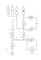
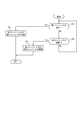
- FIG. 1 is a block diagram of a power supply system 1 according to the first embodiment.
- the solid line connecting the blocks indicates the flow of power.
- broken lines connecting the blocks indicate the flow of control.
- the power supply system 1 is mounted on a vehicle such as a hybrid vehicle or an electric vehicle.
- the power supply system 1 is connected to the AC power supply 2 when charging a first battery 21 described later.
- the AC power supply 2 can be provided in a house, a charging stand, or the like.
- AC power supply 2 may be a commercial AC power supply.
- the AC power supply 2 may be a three-phase type AC power supply.
- the AC power supply 2 may be a single-phase three-wire AC power supply or a single-phase two-wire AC power supply.
- the AC power supply 2 can supply an AC voltage in a range of, for example, 85V to 265V.
- the power supply system 1 includes a first converter 11, a second converter 12, and a third converter 13, which are connected in a loop. Further, the power supply system 1 includes a first battery 21, a second battery 22, a third battery 23, a motor 31, an accessory 32, an electronic control unit (ECU: Electronic Control Unit) 33, a memory 40, , A controller 41. In addition, the power supply system 1 may include a fourth converter 14.
- ⁇ In the power supply system 1 shown in FIG. 1, three converters of a first converter 11, a second converter 12, and a third converter 13 are connected in a loop. However, in the power supply system 1, for example, two converters may be connected in a loop or four or more converters may be connected in a loop according to the number of batteries.
- the nominal voltage of the first battery 21 is a high voltage in the range of, for example, 250 V to 450 V (hereinafter, referred to as “HV”).
- the nominal voltage of the first battery 21 may be any voltage according to the drive voltage of the motor 31.
- the nominal voltage of the second battery 22 is assumed to be 48V.
- the nominal voltage may be any voltage according to the drive voltage of the accessory 32.
- the nominal voltage of the third battery 23 is assumed to be 12V.
- the nominal voltage of the third battery 23 may be any voltage according to the drive voltage of the ECU 33, as long as the nominal voltage is lower than the nominal voltage of the second battery 22.
- the first converter 11 may include a switching element, an inductor, and the like.
- the first converter 11 is capable of bidirectional power conversion.
- the first converter 11 is, for example, a bidirectional DC-DC converter.
- the first converter 11 is capable of bidirectional power conversion between the first battery 21 and the second battery 22.
- the first converter 11 reduces the voltage HV supplied from the first battery 21 to a voltage suitable for charging the second battery 22, and converts the reduced DC voltage to the second voltage. Supply to battery 22.
- the first converter 11 reduces the voltage HV supplied from the first battery 21 to a voltage suitable for driving the auxiliary device 32 based on the control of the controller 41, and 32.
- the first converter 11 boosts the voltage 48 V supplied from the second battery 22 to a voltage suitable for driving the motor 31 and supplies the boosted DC voltage to the motor 31 based on the control of the controller 41. I do.
- the second converter 12 may include a switching element, an inductor, and the like.
- the second converter 12 is capable of bidirectional power conversion.
- the second converter 12 is, for example, a bidirectional DC-DC converter.
- the second converter 12 is capable of bidirectional power conversion between the second battery 22 and the third battery 23.
- the second converter 12 reduces the voltage of 48V supplied from the second battery 22 to a voltage suitable for charging the third battery 23, and converts the reduced DC voltage to the third voltage.
- the battery 23 is supplied.
- the second converter 12 boosts the voltage 12V supplied from the third battery 23 to a voltage suitable for charging the second battery 22, and converts the boosted DC voltage to the second voltage. Supply to battery 22.
- the second converter 12 reduces the voltage of 48 V supplied from the second battery 22 to a voltage suitable for driving the ECU 33 and supplies the reduced DC voltage to the ECU 33.
- the third converter 13 may be configured to include a switching element, an inductor, and the like.
- the third converter 13 is capable of bidirectional power conversion.
- the third converter 13 is, for example, a bidirectional DC-DC converter.
- the third converter 13 is capable of bidirectional power conversion between the first battery 21 and the third battery 23.
- the third converter 13 reduces the voltage HV supplied from the first battery 21 to a voltage suitable for charging the third battery 23, and reduces the DC voltage after the reduction to the third voltage.
- the battery 23 is supplied.
- the third converter 13 reduces the voltage HV supplied from the first battery 21 to a voltage suitable for driving the ECU 33 and supplies the reduced DC voltage to the ECU 33 based on the control of the controller 41.
- the third converter 13 boosts the voltage 12 V supplied from the third battery 23 to a voltage suitable for driving the motor 31 based on the control of the controller 41 and supplies the boosted DC voltage to the motor 31. I do.
- the fourth converter 14 may include a switching element, an inductor, and the like.
- the fourth converter 14 is capable of bidirectional power conversion.
- the fourth converter 14 is, for example, a bidirectional AC-DC converter.
- the fourth converter 14 converts AC power supplied from the AC power supply 2 into DC power under the control of the controller 41. Further, fourth converter 14 boosts the voltage of the converted DC power to voltage HV under the control of controller 41. The fourth converter 14 supplies the boosted DC voltage to the first battery 21.
- the first battery 21 may include a lithium ion battery.
- First battery 21 is provided between first converter 11 and third converter 13. That is, the first battery 21 is provided between the adjacent first converter 11 and third converter 13 in the first to third converters 11 to 13 connected in a loop.
- a positive terminal of the first battery 21 is connected between the first converter 11 and the third converter 13.
- the first battery 21 and the motor 31 are insulated from the outside.
- the first battery 21 is charged by the electric power supplied from the AC power supply 2 via the fourth converter 14, for example.
- the first battery 21 can supply DC power to at least one of the first converter 11, the third converter 13, and the motor 31 by discharging the charged power.
- the first battery 21 is used to supply electric power to the motor 31. Therefore, the nominal capacity of the first battery 21 is larger than the nominal capacity of the second battery 22 and the nominal capacity of the third battery. Therefore, in the power supply system 1, the first battery 21 is charged by the power from the AC power supply 2. Next, the electric power charged in the first battery 21 is discharged to charge the second battery 22 and the third battery 23 as described later.
- the second battery 22 may include a lithium ion battery.
- the second battery 22 is provided between the first converter 11 and the second converter 12. That is, the second battery 22 is provided between the adjacent first converter 11 and second converter 12 in the first to third converters 13 to 13 connected in a loop.
- the positive terminal of the second battery is connected between the first converter 11 and the second converter 12.
- the negative terminal of the second battery 22 is connected to a housing of the vehicle on which the power supply system 1 is mounted.
- the nominal voltage of the second battery 22 is lower than the nominal voltage of the first battery 21.
- the second battery 22 is charged by the electric power supplied from the first battery 21 via, for example, the first converter 11.
- the second battery 22 can supply DC power to at least one of the first converter 11, the second converter 12, and the accessory 32 by discharging the charged power.
- the third battery 23 may include a lithium ion battery.
- Third battery 23 is provided between second converter 12 and third converter 13. That is, the third battery 23 is provided between the adjacent second converter 12 and third converter 13 in the first to third converters 11 to 13 connected in a loop.
- a positive terminal of the third battery 23 is connected between the second converter 12 and the third converter 13.
- the negative terminal of the third battery 23 is connected to a housing of the vehicle on which the power supply system 1 is mounted.
- the nominal voltage of the third battery 23 is lower than the nominal voltage of the second battery 22.
- the third battery 23 is charged by the electric power supplied from the first battery 21 via, for example, the third converter 13.
- the third battery 23 can supply DC power to at least one of the second converter 12, the third converter 13, and the ECU 33 by discharging the charged power.
- the motor 31 generates a rotational driving force by the electric power supplied from the first battery 21.
- the rotational driving force generated by the motor 31 is transmitted to tires of a vehicle on which the power supply system 1 is mounted.
- the vehicle equipped with the power supply system 1 travels by transmitting rotational driving force to tires.
- the motor 31 may be an HEV motor or an EV motor.
- the auxiliary device 32 is driven by the electric power supplied from the second battery 22.
- one accessory 32 is connected to the second battery 22, but a plurality of accessories 32 may be connected to the second battery 22.
- the accessory 32 may be various devices provided in a vehicle on which the power supply system 1 is mounted.
- the accessory 32 may be an electric power steering, an electric suspension, a sensor for automatic driving, an electric actuator, or the like.
- the ECU 33 is driven by electric power supplied from the third battery 23.
- one ECU 33 is connected to the third battery 23, but a plurality of ECUs 33 may be connected to the third battery 23.
- the ECU 33 may be a control unit that controls the motor 31 or a control unit that controls devices included in the accessory 32.
- the memory 40 is connected to the controller 41.
- the memory 40 stores information obtained from the controller 41.
- the memory 40 may function as a working memory of the controller 41.
- the memory 40 may store a program executed by the controller 41.
- the memory 40 is formed of, for example, a semiconductor memory, but is not limited thereto, and may be formed of a magnetic storage medium or may be formed of another storage medium.
- the memory 40 may be included as a part of the controller 41.
- the controller 41 may be configured by a processor such as a CPU (Central Processing Unit) that executes a program defining a control procedure.
- the controller 41 may be a type of the ECU 33.
- the controller 41 can control the first converter 11, the second converter 12, the third converter 13, and the fourth converter 14.
- the controller 41 controls the first converter 11 and the like by outputting a control signal to the first converter 11 and the like.
- the controller 41 may be able to detect an abnormality of the first battery 21, the second battery 22, and the third battery 23.
- the controller 41 detects that the first battery 21 is abnormal.
- the controller 41 may detect the failure of the first battery 21 by using a BMS (Battery Management System) that monitors each cell voltage and the like included in the first battery 21.
- BMS Battery Management System
- the controller 41 detects that the second battery 22 is abnormal.
- the controller 41 detects that the third battery 23 is abnormal.
- the controller 41 detects that the first battery 21 is abnormal when the terminal of the first battery 21 is opened from the first converter 11 or the like and when the terminal of the first battery 21 is short-circuited.
- An open terminal is also referred to as an “open terminal”.
- a short-circuited terminal is also called a “short terminal”.
- the controller 41 may detect the open terminal and the short terminal in the first battery 21 by monitoring the voltage between the terminals of the first battery 21.
- the controller 41 detects that the second battery 22 is abnormal.
- the controller 41 detects that the third battery 23 is abnormal.
- the controller 41 may be able to detect an abnormality of the first converter 11, the second converter 12, and the third converter 13.
- the controller 41 detects that the first converter 11 is abnormal.
- the controller 41 may detect the abnormality of the first converter 11 by monitoring the output of the first converter 11.
- the controller 41 detects that the second converter 12 is abnormal.
- the controller 41 detects that the third converter 13 is abnormal.
- the controller 41 controls the fourth converter 14 by outputting a control signal to the fourth converter 14 while the power supply system 1 is connected to the AC power supply 2, and controls the first battery by the power from the AC power supply 2. Charge 21.
- the controller 41 controls the first converter 11 and the third converter 13, for example, while the vehicle equipped with the power supply system 1 is running, so that the power supplied to the first battery 21 is converted into the second battery 22 and the third battery 23.
- the power paths at this time are the path P1 and the path P2 shown in FIG.
- the path P1 is a path of power flowing from the first battery 21 to the second battery 22 via the first converter 11.
- the path P2 is a path of power flowing from the first battery 21 to the third battery 23 via the third converter 13.
- the second battery 22 is charged, and it becomes possible to supply electric power to the auxiliary device 32. Further, by such control, the third battery 23 is charged, and it becomes possible to supply electric power to the ECU 33 and the controller 41.
- the controller 41 When detecting an abnormality in the first battery 21, the controller 41 disconnects the first battery 21 that has detected the abnormality from other circuit elements by means such as a relay. That is, the controller 41 separates the failed first battery 21 from other circuit elements. Thereafter, the controller 41 controls the first converter 11 to supply the electric power charged in the second battery 22 to the motor 31 as a load connected to the first battery 21.
- the power path at this time is the path P3 shown in FIG.
- the path P3 is a path for electric power flowing from the second battery 22 to the motor 31 via the first converter 11.
- the motor 31 can continue to be driven for a while by the power supplied from the second battery 22.
- the vehicle on which the power supply system 1 is mounted can continue driving the motor 31 for a while, for example, even if an abnormality occurs in the first battery 21 during traveling.
- the vehicle can stop after traveling to a safe position such as the side of a road.
- the controller 41 controls the third converter 13 so that the electric power charged in the third battery 23 is connected to the first battery 21. It may be supplied to the motor 31 as a load.
- the power path at this time is the path P4 shown in FIG.
- the path P4 is a path of electric power flowing from the third battery 23 to the motor 31 via the third converter 13.
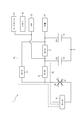
- the controller 41 When detecting an abnormality in the second battery 22, the controller 41 disconnects the second battery 22 that has detected the abnormality from other circuit elements by means such as a relay. That is, the controller 41 separates the failed second battery 22 from other circuit elements. After that, the controller 41 controls the first converter 11 to supply the electric power charged in the first battery 21 to the accessory 32 as a load connected to the second battery 22.
- the power path at this time is the path P5 shown in FIG.
- the path P5 is a path for electric power flowing from the first battery 21 to the accessory 32 via the first converter 11.
- the auxiliary device 32 can continue to be driven by the electric power from the first battery 21. That is, the vehicle equipped with the power supply system 1 can drive the accessory 32 even if an abnormality occurs in the second battery 22 during traveling, for example.
- the controller 41 may control the second converter 12 and the third converter 13 to supply the power charged in the first battery 21 to the auxiliary device 32 as a load connected to the second battery 22.
- the controller 41 detects the abnormality of the first converter 11 in addition to the abnormality of the second battery 22, the controller 41 controls the second converter 12 and the third converter 13 to supplement the power from the first battery 21. Machine 32.
- the power path at this time is the path P6 shown in FIG.
- the path P6 is a path of electric power flowing from the first battery 21 to the auxiliary device 32 via the third converter 13 and the second converter 12.
- the controller 41 When detecting an abnormality of the third battery 23, the controller 41 disconnects the third battery 23 that has detected the abnormality from other circuit elements by means such as a relay. That is, the controller 41 separates the failed third battery 23 from other circuit elements. Thereafter, the controller 41 controls the third converter 13 to supply the electric power charged in the first battery 21 to the ECU 33 as a load connected to the third battery 23 and the controller 41.
- the power path at this time is the path P7 shown in FIG.
- the path P7 is a path of electric power flowing from the first battery 21 to the ECU 33 and the like via the third converter 13.
- the ECU 33 and the like can continue to be driven by the electric power from the first battery 21. That is, the vehicle equipped with the power supply system 1 can continue to drive the ECU 33 and the like even if an abnormality occurs in the third battery 23 during traveling, for example.
- the controller 41 controls the second converter 12 to output the electric power charged in the second battery 22 to the third battery 23.
- the load may be supplied to the ECU 33 as a load connected to the ECU 23.
- the power path at this time is the path P8 shown in FIG.
- the path P8 is a path for electric power flowing from the second battery 22 to the ECU 33 and the like via the second converter 12.
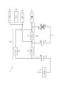
- the controller 41 When detecting an abnormality in the first converter 11, the controller 41 disconnects the first converter 11 that has detected the abnormality from other circuit elements by means such as a relay. That is, the controller 41 separates the failed first converter 11 from other circuit elements.
- the controller 41 controls the second converter 12 and the third converter 13 to supply the electric power charged in the first battery 21 to the second battery 22 and the third battery 23.
- the power path at this time is the path P9 shown in FIG.
- the path P9 is a path for power flowing from the first battery 21 to the third battery 23 via the third converter 13, and from the first battery 21 to the second battery 22 via the third converter 13 and the second converter 12. This is the path of the flowing power.
- the second battery 22 and the third battery 23 can be charged by the electric power from the first battery 21.
- the auxiliary device 32 can be continuously driven by the electric power supplied from the second battery 22.
- the ECU 33 and the controller 41 can continue to be driven by the electric power supplied from the third battery 23.
- the controller 41 When detecting an abnormality in the third converter 13, the controller 41 disconnects the third converter 13 that has detected the abnormality from other circuit elements by means such as a relay. That is, the controller 41 separates the failed third converter 13 from other circuit elements.
- the controller 41 controls the first converter 11 and the second converter 12 to supply the power charged in the first battery 21 to the second battery 22 and the third battery 23.
- the power path at this time is the path P10 shown in FIG.
- the path P10 is a path for power flowing from the first battery 21 to the second battery 22 via the first converter 11, and a path from the first battery 21 to the third battery 23 via the first converter 11 and the second converter 12. This is the path of the flowing power.
- the second battery 22 and the third battery 23 can be charged by the electric power from the first battery 21.
- the auxiliary device 32 can be continuously driven by the electric power supplied from the second battery 22.
- the ECU 33 and the controller 41 can continue to be driven by the electric power supplied from the third battery 23.
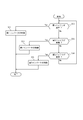
- FIG. 7 is a flowchart illustrating an example of the operation of the power supply system 1 according to the first embodiment. For example, when the vehicle equipped with the power supply system 1 starts running, the controller 41 starts the processing illustrated in FIG. When the vehicle equipped with the power supply system 1 stops running, the controller 41 ends the process illustrated in FIG.
- Step S10 determines whether the first battery 21 is abnormal.
- step S10: Yes determines that the first battery 21 is abnormal
- step S11: No determines that the first battery 21 is abnormal
- step S12: No determines that the first battery 21 is abnormal
- step S11 the controller 41 controls the first converter 11 to supply the electric power charged in the second battery 22 to the motor 31 as a load connected to the first battery 21 (see FIG. Path P3).
- step S12 the controller 41 determines whether the second battery 22 is abnormal.
- step S12: Yes the process proceeds to step S13.
- step S12: No the process proceeds to step S14.
- step S13 the controller 41 controls the first converter 11 to supply the power charged in the first battery 21 to the accessory 32 as a load connected to the second battery 22 (see: Route P5 in FIG. 3).
- step S14 the controller 41 determines whether the third battery 23 is abnormal.
- step S14: Yes the process proceeds to step S15.
- step S14: No the process returns to step S10.
- step S15 the controller 41 controls the third converter 13 to supply the power charged in the first battery 21 to the ECU 33 as a load connected to the third battery 23 and the controller 41 (see : Path P7 in FIG. 4).
- step S11 the controller 41 controls the third converter 13 to supply the electric power charged in the third battery 23 to the motor 31 as a load connected to the first battery 21. Good (see: path P4 in FIG. 2).
- the controller 41 controls the second converter 12 and the third converter 13 to use the power charged in the first battery 21 as a load connected to the second battery 22. It may be supplied to the auxiliary machine 32 (see the route P6 in FIG. 3).
- step S15 the controller 41 controls the second converter 12 to supply the electric power charged in the second battery 22 to the ECU 33 or the like as a load connected to the third battery 23. Good (see: path P8 in FIG. 4).
- FIG. 8 is a flowchart illustrating another example of the operation of the power supply system 1 according to the first embodiment.
- the controller 41 starts the process illustrated in FIG.
- the controller 41 ends the processing illustrated in FIG. Note that the controller 41 may execute the processing shown in FIG. 8 in parallel with the processing shown in FIG.
- Step S20 determines whether or not the first converter 11 is abnormal.
- step S20: Yes determines that the first converter 11 is abnormal
- step S21 determines whether or not the first converter 11 is abnormal
- step S21 determines whether or not the first converter 11 is abnormal
- step S22 determines whether or not the first converter 11 is abnormal
- step S21 the controller 41 controls the second converter 12 and the third converter 13 to supply the power charged in the first battery 21 to the second battery 22 and the third battery 23 (see: Path P9 in FIG. 5).
- step S22 the controller 41 determines whether the third converter 13 is abnormal.
- step S22: Yes the process proceeds to step S23.
- step S22: No the controller 41 returns to the processing of step S20.
- step S23 the controller 41 controls the first converter 11 and the second converter 12 to supply the power charged in the first battery 21 to the second battery 22 and the third battery 23 (see: Route P10 in FIG. 6).
- the first converter 11, the second converter 12, and the third converter 13 are connected in a loop. Further, the first battery 21 is provided between the first converter 11 and the third converter 13, the second battery 22 is provided between the first converter 11 and the second converter 12, and the third battery 23 is provided It is provided between the second converter 12 and the third converter. With such a configuration, it is possible to continue to supply power to the load even if any of the first converter 11 and the like and the first battery 21 and the like included in the power supply system 1 have an abnormality. Therefore, according to the first embodiment, the power supply system 1 with improved reliability can be provided.
- FIG. 9 is a circuit diagram of a DC-DC converter according to the second embodiment.
- FIG. 9 is a circuit diagram of the converter 10.
- Converter 10 is connected between battery 20A and battery 20B.
- the nominal voltage of battery 20A is lower than the nominal voltage of battery 20B. That is, when the converter 10 is the first converter 11, the battery 20A becomes the second battery 22 shown in FIG. 1, and the battery 20B becomes the first battery 21 shown in FIG.
- converter 10 is second converter 12
- battery 20A becomes third battery 23 shown in FIG. 1 and battery 20B becomes second battery 22 shown in FIG.
- converter 10 is third converter 13
- battery 20A becomes third battery 23 shown in FIG. 1 and battery 20B becomes first battery 21 shown in FIG.
- the converter 10 includes a drive circuit 50, switching circuits 51A and 51B, smoothing capacitors 52A and 52B, and a transformer 60. Further, converter 10 may include switches 90A and 90B for disconnecting the circuit from transformer 60.
- the drive circuit 50 generates a pulse-wave drive signal for turning on and off the switching circuits 51A and 51B at a predetermined timing based on the control signal from the controller 41 shown in FIG.
- the frequency of the drive signal that is a pulse wave is also described as “drive frequency”.
- the drive circuit 50 outputs the generated drive signal to the switching circuits 51A and 51B.
- the drive circuit 50 generates a control signal for controlling the switches 90A and 90B to be turned on and off based on the control signal from the controller 41 shown in FIG.
- the drive circuit 50 outputs the generated control signal to the switches 90A and 90B.
- the controller 41 turns on 90A and 90B when operating the converter 10, and turns off at other times.
- the switching circuit 51A is connected between the battery 20A and the transformer 60.
- the switching circuit 51A is a full-bridge circuit. When converter 10 boosts the voltage on battery 20A side to the voltage on battery 20B side, switching circuit 51A is driven by a drive signal from drive circuit 50.
- the switching circuit 51A has switching elements Q1A, Q2A, QA3, and Q4A.
- the switching elements Q1A to Q4A may be N-type MOSFETs.
- the switching elements Q1A to Q4A may be power MOSFETs.
- the switching elements Q1A to Q4A are not limited to MOSFETs.
- switching elements Q1A to Q4A may be bipolar transistors or IGBTs (Insulated Gate Bipolar Transistor).
- the drains of the switching elements Q1A and Q3A are connected to the positive terminal of the battery 20A.
- the sources of the switching elements Q2A and Q4A are connected to the negative terminal of the battery 20A.
- the source of the switching element Q1A and the drain of the switching element Q2A are connected to one end of the winding 70 of the transformer 60.
- the source of the switching element Q3A and the drain of the switching element Q4A are connected to the other end of the winding 70 of the transformer 60.
- the drive signal from the drive circuit 50 is input to the gates of the switching elements Q1A to Q4A.
- switching elements Q1A and Q4A are turned on by the input of the drive signal, switching elements Q2A and Q3A are turned off.
- switching elements Q1A and Q4A are turned off, switching elements Q2A and Q3A are turned on.
- the switching elements Q1A and Q4A and the switching elements Q2A and Q3A alternately turn on and off at the drive frequency.
- an alternating current having the drive frequency flows through the winding 70 of the transformer 60.
- an induced electromotive force is generated in the winding 80 of the transformer 60.
- the switching circuit 51B is connected between the battery 20B and the transformer 60.
- the switching circuit 51B is a full-bridge type circuit. When converter 10 steps down the voltage of battery 20B to the voltage of battery 20A, switching circuit 51B is driven by a drive signal from drive circuit 50.
- the switching circuit 51B has switching elements Q1B, Q2B, Q3B, Q4B.
- the switching elements Q1B to Q4B may be N-type MOSFETs.
- the switching elements Q1B to Q4B may be power MOSFETs.
- the switching elements Q1B to Q4B are not limited to MOSFETs.
- switching elements Q1B-Q4B may be bipolar transistors or IGBTs.
- the drains of the switching elements Q1B and Q3B are connected to the positive terminal of the battery 20B.
- the sources of the switching elements Q2B and Q4B are connected to the negative terminal of the battery 20B.
- the source of the switching element Q1B and the drain of the switching element Q2B are connected to one end of the winding 80 of the transformer 60.
- the source of the switching element Q3B and the drain of the switching element Q4B are connected to the other end of the winding 80 of the transformer 60.
- the drive signal from the drive circuit 50 is input to the gates of the switching elements Q1B to Q4B.
- switching elements Q1B and Q4B are turned on by the input of the drive signal, switching elements Q2B and Q3B are turned off.
- switching elements Q1B and Q4B are turned off, switching elements Q2B and Q3B are turned on.
- the switching elements Q1B and Q4B and the switching elements Q2B and Q3B are alternately turned on and off at the drive frequency. Since the switching elements Q1B and Q4B and the switching elements Q2B and Q3B are alternately turned on and off at the drive frequency, an alternating current having the drive frequency flows through the winding 80 of the transformer 60.
- an induced electromotive force is generated in the winding 70 of the transformer 60.
- the smoothing capacitor 52A is provided between the battery 20A and the switching circuit 51A.
- the smoothing capacitor 52A smoothes the voltage between the switching circuit 51A and the battery 20A.
- the smoothing capacitor 52B is provided between the battery 20B and the switching circuit 51B. Smoothing capacitor 52B smoothes the voltage between switching circuit 51B and battery 20B.
- the transformer 60 is an insulating transformer.
- the transformer 60 may be a planar transformer.
- the transformer 60 is not limited to a planar type transformer.
- the transformer 60 may be a transformer including a bobbin and a conductive line.
- the transformer 60 of the first converter 11 is referred to as a "transformer 61".
- the transformer 60 of the second converter 12 is referred to as a “transformer 62”.
- the transformer 60 of the third converter 13 is described as “transformer 63”.
- the transformer 60 has a core 65, a winding 70, and a winding 80.
- the transformers 61, 62, and 63 share the core 65. This configuration will be described later with reference to FIGS.
- the winding 70 is formed as a conductor pattern when the transformer 60 is a planar type transformer. Winding 70 is also referred to as “primary winding” when converter 10 boosts the voltage on battery 20A side to the voltage on battery 20B side. When converter 10 steps down the voltage on battery 20B side to the voltage on battery 20A side, winding 70 is also referred to as “secondary winding”. The number of turns of the winding 70 and the number of turns of the winding 80 are appropriately set based on the voltage at which the converter 10 steps up and steps down.
- windings 70 of the transformer 61 that is, the first converter 11
- windings 70 of the transformer 62 that is, the second converter 12
- winding 72 the winding 70 included in the transformer 63
- winding 73 the winding 70 included in the transformer 63
- winding 80 is formed as a conductor pattern when the transformer 60 is a planar type transformer. Winding 80 is also referred to as “secondary winding” when converter 10 boosts the voltage on battery 20A side to the voltage on battery 20B side. When converter 10 steps down the voltage on battery 20B side to the voltage on battery 20A side, winding 70 is also referred to as “primary winding”.
- windings 80 included in the transformer 61 are described as “windings 81”.
- the winding 80 of the transformer 62 (that is, of the second converter 12) is referred to as “winding 82”.
- the winding 80 of the transformer 63 (that is, the third converter 13) is referred to as “winding 83”.
- the switches 90A, 90B may be N-type MOSFETs, like the switching element Q1A.
- the switches 90A and 90B may be power MOSFETs.
- the switches 90A and 90B are not limited to MOSFETs.
- switches 90A and 90B may be bipolar transistors or IGBTs.
- switches 90A and 90B included in each of the first converter 11, the second converter 12, and the third converter 13 are distinguished, the switches 90A and 90B included in the first converter 11 are referred to as “switch 91A” and “switch 91B”. ".
- the switches 90A and 90B included in the second converter 12 are referred to as “switch 92A” and “switch 92B”.
- the switches 90A and 90B included in the third converter 13 are described as “switch 93A” and “switch 93B”.
- the switch 90A is provided between the battery 20A and the switching circuit 51A.
- the switch 90A is provided between the negative terminal of the battery 20A and the source of the switching element Q2A of the switching circuit 51A.
- the switch 90B is provided between the battery 20B and the switching circuit 51B.
- the switch 90B is provided between the negative terminal of the battery 20B and the source of the switching element Q4B of the switching circuit 51B.
- the switches 90A and 90B disconnect the transformer 60 from other components based on a control signal from the drive circuit 50.
- the switch 90A disconnects the connection between the transformer 60 and the switching circuit 51A from the smoothing capacitor 52A and the battery 20A by turning off based on a control signal from the drive circuit 50.
- the switch 90B is turned off based on a control signal from the drive circuit 50 to disconnect the connection between the transformer 60 and the switching circuit 51B and the smoothing capacitor 52B and the battery 20B.
- the switch 90A may be provided between the positive terminal of the battery 20A and the drain of the switching element Q1A of the switching circuit 51A.
- the switch 90B may be provided between the positive terminal of the battery 20B and the drain of the switching element Q3B of the switching circuit 51B.
- the switches 90A and 90B may be P-type MOSFETs.
- FIG. 10 is a circuit diagram of the AC-DC converter according to the second embodiment.
- FIG. 10 is a circuit diagram of the fourth converter 14.
- Fourth converter 14 includes converter 10 and rectifier circuit 15.
- the converter 10 is connected between the rectifier circuit 15 and the first battery 21.
- Converter 10 boosts the voltage from rectifier circuit 15 to a predetermined voltage and then supplies it to first battery 21.
- the transformer 60 included in the converter 10 of the fourth converter 14 is also described as “transformer 64”.
- the winding 70 of the transformer 64 is also described as “winding 74”.
- the winding 80 of the transformer 64 is also described as “winding 84”.
- the switches 90A and 90B included in the converter 10 of the fourth converter 14 are also referred to as “switches 94A” and “switches 94B”.
- the transformer 64 may be configured by sharing the core 65 with the transformers 61, 62, 63 described above. This configuration will be described later with reference to FIGS.
- the rectifier circuit 15 may include a switching element and an inductor.
- the rectifier circuit 15 may be a three-phase full-wave rectification circuit or a three-phase half-wave rectification circuit.
- the rectifier circuit 15 can be connected to the AC power supply 2.
- the rectifier circuit 15 converts an AC current from the AC power supply 2 into a DC current by rectifying the AC current.
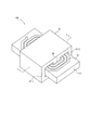
- FIG. 11 is a perspective view of a planar transformer according to the second embodiment.
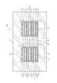
- FIG. 12 is a cross-sectional view of the planar transformer taken along line LL shown in FIG. In FIG. 12, the magnetic flux of the closed magnetic path formed inside the core 65 is indicated by a broken line.
- the planar transformer 100 includes a core 65, windings 71, 72, 73, 74, windings 81, 82, 83, 84, and a substrate 110.
- the core 65 may be made of a magnetic material such as ferrite.
- the core 65 may be configured by combining a pair of E-shaped cores having an E-shaped cross-section such that three legs face each other. As shown in FIG. 12, the core 65 includes a middle leg 66, side legs 67-1 and 67-2, an upper surface 68, and a lower surface 69.
- the middle leg portion 66 is inserted into the opening located at the center of the windings 71 to 74 and the opening located at the center of the windings 81 to 84.
- the windings 71 to 74 and the windings 81 to 84 are wound around the middle leg 66.
- the middle leg 66 may be provided with a gap 66a.
- the side leg 67-1 is located on one outside of the substrate 110 as shown in FIG.
- the side leg 67-2 is located outside the other side of the substrate 110 as shown in FIG.
- the upper surface portion 68 connects the upper portion of the middle leg portion 66 and the upper portions of the side leg portions 67-1, 67-2 as shown in FIG.
- the lower surface portion 69 connects the lower portion of the middle leg portion 66 and the lower portions of the side leg portions 67-1, 67-2, as shown in FIG.
- the windings 71 to 74 and 81 to 84 are conductor patterns formed using a conductor such as copper.
- the windings 71 to 74 and 81 to 84 have openings at their centers. As described above, the windings 71 and 81 are included in the transformer 61. Further, the windings 72 and 82 are included in the transformer 62. The windings 73 and 83 are included in the transformer 63. The windings 74 and 84 are included in the transformer 64.
- the substrate 110 includes an insulating material.
- the substrate 110 includes substrates 111, 112, 113, 114, 115, 116, 117 and 118 as shown in FIG.
- the winding 81 is arranged on the upper surface of the substrate 111.
- the winding 71 is arranged on the lower surface of the substrate 111.
- the winding 82 is arranged on the upper surface of the substrate 112.
- the winding 72 is arranged on the lower surface of the substrate 112.
- the winding 83 is arranged on the upper surface of the substrate 113.
- the winding 73 is arranged on the lower surface of the substrate 113.
- the winding 84 is arranged on the upper surface of the substrate 114.
- the winding 74 is arranged on the lower surface of the substrate 114.
- the substrate 115 is disposed between the winding 71 and the winding 82.
- the board 116 is arranged between the winding 72 and the winding 83.
- the board 117 is arranged between the winding 73 and the winding 84.
- each of the transformers 61 to 64 of the first converter 11, the second converter 12, the third converter 13, and the fourth converter 14 can be configured to share the core 65.
- the first converter 11, the second converter 12, the third converter 13, and the fourth converter 14 can be downsized. Therefore, the power supply system 1 can be downsized.
- the transformers 61 to 64 as planar type transformers, the first converter 11, the second converter 12, the third converter 13, and the fourth converter 14 can be further reduced in size.
- Bmax is the saturation magnetic flux density of the core 65.
- Bmax is a value corresponding to the magnetic characteristics of the core 65. That is, Bmax is a value corresponding to the magnetic material forming the core 65.
- A is the cross-sectional area of the middle leg 66 shown in FIG.
- Magnetic flux ⁇ is magnetic flux ⁇ generated in middle leg portion 66 when converter 10 shown in FIG. 9 is driven.
- the magnetic flux ⁇ is calculated by the following equations (2) and (3).
- V is a voltage applied to the core 65 when the converter 10 shown in FIG. 9 is driven.
- n is the number of turns of the winding 80 shown in FIG. D is the duty of the pulse wave (drive signal) for turning on and off the switching elements Q1A to Q4A shown in FIG. D may be 0.5 in a bidirectional system such as converter 10 shown in FIG. T is a period of a pulse wave (drive signal) for turning on and off the switching elements Q1A to Q4A shown in FIG. T is also called a PWM (Pulse Wide Modulation) cycle.
- the driving frequency of the first converter 11 is set to be higher than the driving frequencies of the second converter 12, the third converter 13, and the fourth converter 14. Further, the driving frequency of the first converter 11 is set so as to satisfy Expression (1).
- the drive frequency f of the first converter 11 is determined according to the magnetic characteristics of the core 65. With such a configuration, magnetic saturation in the core 65 can be prevented. Further, by driving the second converter 12, the third converter 13, and the fourth converter 14 at a drive frequency lower than the drive frequency of the first converter 11, the power conversion efficiency of the second converter 12 and the like can be improved. it can.
- controller processing In the second embodiment, the controller 41 shown in FIG. 1 controls the switches 91A to 94A and 91B to 94B so that the first converter 11, the second converter 12, the third converter 13, and the fourth converter 14 are not driven at the same time. Control.
- the controller 41 shown in FIG. 1 drives the first converter 11 among the first converter 11, the second converter 12, the third converter 13, and the fourth converter 14. That is, of the first converter 11, the second converter 12, the third converter 13, and the fourth converter 14, the second converter 12, the third converter 13, and the fourth converter 14 are converters that are not controlled by the controller 41. Shall be.
- the controller 41 controls so as not to drive the second converter 12, the third converter 13, and the fourth converter 14.
- the controller 41 shown in FIG. 1 outputs a control signal to the drive circuit 50 of the first converter 11 shown in FIG. 9 so that the switches 91A and 91B are turned on.
- the controller 41 outputs a control signal to the drive circuit 50 of each of the second converter 12, the third converter 13, and the fourth converter 14 shown in FIG. 9 so that the switches 92A to 94A and 92B to 94B are turned off. I do.
- the transformer 61 is connected to other components such as the smoothing capacitor 52A.
- the transformers 62 to 64 are separated from other components.
- the second converter 12, the third converter 13, and the fourth converter 14, which are not driven it is possible to prevent an unintended current from leaking from the transformers 62 to 64 to other components.
- switches 90A and 90B are provided is not limited to the configuration illustrated in FIG.
- a configuration as shown in FIG. 13 may be used.
- FIG. 13 is a circuit diagram of a DC-DC converter according to another example of the second embodiment.
- FIG. 13 shows a part of the configuration shown in FIG.
- the same DC-DC converter can be used for the first converter 11a, the second converter 12a, the third converter 13a, and the fourth converter 14a.
- the first converter 11a will be described as an example.
- the first converter 11a has switches 121A and 122A between the winding 71 and the switching circuit 51A.
- the first converter 11a has switches 121B and 122B between the winding 81 and the switching circuit 51B.
- the switches 121A and 122A may be configured to include a relay circuit.
- the switch 121A is provided between one end of the winding 71 and the source of the switching element Q1A and the drain of the switching element Q2A of the switching circuit 51A shown in FIG.
- the switch 122A is provided between the other end of the winding 71 and the source of the switching element Q3A and the drain of the switching element Q4A of the switching circuit 51A shown in FIG.
- the switches 121A and 122A switch between conduction and interruption based on a control signal from the controller 41 shown in FIG.
- the switches 121B and 122B may be configured to include a relay circuit.
- the switch 121B is provided between one end of the winding 81 and the source of the switching element Q1B and the drain of the switching element Q2B of the switching circuit 51B shown in FIG.
- the switch 122B is provided between the other end of the winding 81 and the source of the switching element Q3B and the drain of the switching element Q4B of the switching circuit 51B shown in FIG.
- the switches 121B and 122B switch between conduction and interruption based on a control signal from the controller 41 shown in FIG.
- the transformers 61 to 64 have been described as being configured to share the core 65 as shown in FIGS.
- the transformers 61 to 63 may be configured to share the core 65.
- REFERENCE SIGNS LIST 1 power supply system 2 AC power supply 10 converter 11, 11a first converter 12, 12a second converter 13, 13a third converter 14, 14a fourth converter 15 rectifier circuit 20A, 20B battery 21 first battery 22 second battery 23 third Battery 31 Motor (load) 32 Auxiliary equipment (load) 33 ECU (load) Reference Signs List 40 memory 41 controller 50 drive circuit 51A, 51B switching circuit 52A, 52B smoothing capacitor 60, 61 to 64 transformer 65 core 66 middle leg 66a gap 67-1, 67-2 side leg 68 upper surface portion 69 lower surface portion 70 to 74 , 80 to 84 Windings 90A to 94A, 90B to 94B Switch 100 Planar type transformer 110 to 117 Board 121A, 121B, 122A, 122B Switch P1 to P10 Path Q1A to Q4A, Q1B to Q4B Switching element
Landscapes
- Engineering & Computer Science (AREA)
- Power Engineering (AREA)
- Manufacturing & Machinery (AREA)
- Chemical & Material Sciences (AREA)
- Chemical Kinetics & Catalysis (AREA)
- Electrochemistry (AREA)
- General Chemical & Material Sciences (AREA)
- Mechanical Engineering (AREA)
- Transportation (AREA)
- Life Sciences & Earth Sciences (AREA)
- Sustainable Development (AREA)
- Sustainable Energy (AREA)
- Business, Economics & Management (AREA)
- Emergency Management (AREA)
- Microelectronics & Electronic Packaging (AREA)
- Electric Propulsion And Braking For Vehicles (AREA)
- Charge And Discharge Circuits For Batteries Or The Like (AREA)
- Secondary Cells (AREA)
Abstract
La présente invention concerne un système d'alimentation électrique d'une plus grande fiabilité. Le système d'alimentation 1 comprend un premier convertisseur 11, un second convertisseur 12 et un troisième convertisseur 13 connectés en boucle. Le système d'alimentation 1 comprend également une première batterie 21, une seconde batterie 22, une troisième batterie 23 et un dispositif de commande 41. Le premier convertisseur 11, le second convertisseur 12 et le troisième convertisseur 13 sont capables d'une conversion bidirectionnelle de la puissance. La première batterie 21 est prévue entre le premier convertisseur 11 et le troisième convertisseur 13, qui sont adjacents. La seconde batterie 22 est prévue entre le premier convertisseur 11 et le second convertisseur 12, qui sont adjacents. La troisième batterie 23 est prévue entre le second convertisseur 12 et le troisième convertisseur 13, qui sont adjacents. Le système d'alimentation électrique 1 est capable de commander le premier convertisseur 11, le second convertisseur 12 et le troisième convertisseur 13.
Priority Applications (2)
| Application Number | Priority Date | Filing Date | Title |
|---|---|---|---|
| DE112019004360.9T DE112019004360T5 (de) | 2018-08-29 | 2019-08-01 | Stromversorgungssystem |
| CN201980045373.1A CN112400264A (zh) | 2018-08-29 | 2019-08-01 | 电源系统 |
Applications Claiming Priority (2)
| Application Number | Priority Date | Filing Date | Title |
|---|---|---|---|
| JP2018160821A JP7041600B2 (ja) | 2018-08-29 | 2018-08-29 | 電源システム |
| JP2018-160821 | 2018-08-29 |
Publications (1)
| Publication Number | Publication Date |
|---|---|
| WO2020044938A1 true WO2020044938A1 (fr) | 2020-03-05 |
Family
ID=69643547
Family Applications (1)
| Application Number | Title | Priority Date | Filing Date |
|---|---|---|---|
| PCT/JP2019/030326 WO2020044938A1 (fr) | 2018-08-29 | 2019-08-01 | Système d'alimentation électrique |
Country Status (4)
| Country | Link |
|---|---|
| JP (1) | JP7041600B2 (fr) |
| CN (1) | CN112400264A (fr) |
| DE (1) | DE112019004360T5 (fr) |
| WO (1) | WO2020044938A1 (fr) |
Cited By (3)
| Publication number | Priority date | Publication date | Assignee | Title |
|---|---|---|---|---|
| US20220399727A1 (en) * | 2021-06-14 | 2022-12-15 | Aptiv Technologies Limited | Electrical Architecture |
| JP2023046105A (ja) * | 2021-09-22 | 2023-04-03 | 本田技研工業株式会社 | 車両電源システム |
| WO2023112766A1 (fr) * | 2021-12-15 | 2023-06-22 | 株式会社Gsユアサ | Système de source d'alimentation et procédé de commande pour système de source d'alimentation |
Families Citing this family (3)
| Publication number | Priority date | Publication date | Assignee | Title |
|---|---|---|---|---|
| JP7010989B2 (ja) | 2020-03-11 | 2022-01-26 | 本田技研工業株式会社 | 車両用電源装置 |
| JP7010988B2 (ja) | 2020-03-11 | 2022-01-26 | 本田技研工業株式会社 | 車両用電源装置 |
| CN113386571A (zh) * | 2021-06-30 | 2021-09-14 | 北京百度网讯科技有限公司 | 无人驾驶供电系统、供电控制方法、动力域控制器及车辆 |
Citations (7)
| Publication number | Priority date | Publication date | Assignee | Title |
|---|---|---|---|---|
| JP2006238675A (ja) * | 2005-02-28 | 2006-09-07 | Tdk Corp | 電力変換装置及び電力変換装置への過熱保護温度設定方法 |
| JP2010206864A (ja) * | 2009-02-27 | 2010-09-16 | Panasonic Corp | 電源装置 |
| JP2011030308A (ja) * | 2009-07-22 | 2011-02-10 | Aisan Industry Co Ltd | 電動車両用電源の電力供給制御装置 |
| JP2011036101A (ja) * | 2009-08-05 | 2011-02-17 | Honda Motor Co Ltd | 電力供給システム |
| JP2012023791A (ja) * | 2010-07-12 | 2012-02-02 | Mitsubishi Electric Corp | 車載電源装置 |
| WO2014132452A1 (fr) * | 2013-03-01 | 2014-09-04 | 富士電機株式会社 | Système d'alimentation électrique |
| JP6323635B1 (ja) * | 2017-11-24 | 2018-05-16 | 三菱電機株式会社 | 並列電源装置 |
Family Cites Families (3)
| Publication number | Priority date | Publication date | Assignee | Title |
|---|---|---|---|---|
| EP3113315A1 (fr) * | 2015-07-02 | 2017-01-04 | Hella KGaA Hueck & Co | Système de charge de batterie à double tension automobile |
| KR20170086298A (ko) * | 2016-01-18 | 2017-07-26 | 현대자동차주식회사 | 전기차량의 충전제어 시스템 |
| US10348088B2 (en) * | 2016-12-02 | 2019-07-09 | Lear Corporation | Bi-directional low voltage DC to AC inverter |
-
2018
- 2018-08-29 JP JP2018160821A patent/JP7041600B2/ja active Active
-
2019
- 2019-08-01 CN CN201980045373.1A patent/CN112400264A/zh active Pending
- 2019-08-01 WO PCT/JP2019/030326 patent/WO2020044938A1/fr active Application Filing
- 2019-08-01 DE DE112019004360.9T patent/DE112019004360T5/de active Pending
Patent Citations (7)
| Publication number | Priority date | Publication date | Assignee | Title |
|---|---|---|---|---|
| JP2006238675A (ja) * | 2005-02-28 | 2006-09-07 | Tdk Corp | 電力変換装置及び電力変換装置への過熱保護温度設定方法 |
| JP2010206864A (ja) * | 2009-02-27 | 2010-09-16 | Panasonic Corp | 電源装置 |
| JP2011030308A (ja) * | 2009-07-22 | 2011-02-10 | Aisan Industry Co Ltd | 電動車両用電源の電力供給制御装置 |
| JP2011036101A (ja) * | 2009-08-05 | 2011-02-17 | Honda Motor Co Ltd | 電力供給システム |
| JP2012023791A (ja) * | 2010-07-12 | 2012-02-02 | Mitsubishi Electric Corp | 車載電源装置 |
| WO2014132452A1 (fr) * | 2013-03-01 | 2014-09-04 | 富士電機株式会社 | Système d'alimentation électrique |
| JP6323635B1 (ja) * | 2017-11-24 | 2018-05-16 | 三菱電機株式会社 | 並列電源装置 |
Cited By (5)
| Publication number | Priority date | Publication date | Assignee | Title |
|---|---|---|---|---|
| US20220399727A1 (en) * | 2021-06-14 | 2022-12-15 | Aptiv Technologies Limited | Electrical Architecture |
| US11804720B2 (en) * | 2021-06-14 | 2023-10-31 | Aptiv Technologies Limited | Electrical architecture |
| JP2023046105A (ja) * | 2021-09-22 | 2023-04-03 | 本田技研工業株式会社 | 車両電源システム |
| US11979055B2 (en) | 2021-09-22 | 2024-05-07 | Honda Motor Co., Ltd. | Vehicle power supply system |
| WO2023112766A1 (fr) * | 2021-12-15 | 2023-06-22 | 株式会社Gsユアサ | Système de source d'alimentation et procédé de commande pour système de source d'alimentation |
Also Published As
| Publication number | Publication date |
|---|---|
| JP7041600B2 (ja) | 2022-03-24 |
| CN112400264A (zh) | 2021-02-23 |
| DE112019004360T5 (de) | 2021-06-10 |
| JP2020036448A (ja) | 2020-03-05 |
Similar Documents
| Publication | Publication Date | Title |
|---|---|---|
| WO2020044938A1 (fr) | Système d'alimentation électrique | |
| US11097626B2 (en) | Vehicle electrical systems, charging system, charging station, and method for transmitting electrical energy | |
| CN112513651B (zh) | 用于检测绝缘故障的方法 | |
| US9948219B2 (en) | Rotating electrical machine control device | |
| US8692508B2 (en) | Battery voltage monitoring device | |
| TWI625021B (zh) | 電力轉換系統 | |
| RU2480348C2 (ru) | Гибридное транспортное средство | |
| US9493081B2 (en) | Power supply system, vehicle equipped with the same, and control method for power supply system | |
| US10862315B2 (en) | Device and method for supplying energy to a plurality of energy storage components and/or for providing energy stored within the energy storage components | |
| US20170282747A1 (en) | Charging system for vehicle battery | |
| US9559620B2 (en) | Power supply device and method of controlling the same | |
| KR20170137490A (ko) | Obc 및 인버터 통합 모듈 및 그 제어 방법 | |
| JP2003180002A (ja) | 車両用電源装置 | |
| JPWO2020230202A1 (ja) | 変換装置、変換システム、切替装置、それらを含む車両、及び制御方法 | |
| WO2015004948A1 (fr) | Dispositif de commande de décharge | |
| CN107251392A (zh) | Dc/dc转换装置 | |
| US11305655B2 (en) | Electric power conversion system for vehicle and control method thereof | |
| US11870360B2 (en) | Bidirectional insulating DC-DC converter, control apparatus therefor, and operating method thereof | |
| JP2012085447A (ja) | Ac−dcコンバータ | |
| CN112238770A (zh) | 电源装置 | |
| US20220274498A1 (en) | Discharging vehicle and vehicle charging system | |
| JP6815762B2 (ja) | 電力変換システム | |
| CN111092464A (zh) | 带有可配置输出转换器的车辆动力系统 | |
| US11724612B2 (en) | Bidirectional charging system for vehicle | |
| CN220359039U (zh) | 磁集成电路及电动汽车 |
Legal Events
| Date | Code | Title | Description |
|---|---|---|---|
| 121 | Ep: the epo has been informed by wipo that ep was designated in this application |
Ref document number: 19856144 Country of ref document: EP Kind code of ref document: A1 |
|
| 122 | Ep: pct application non-entry in european phase |
Ref document number: 19856144 Country of ref document: EP Kind code of ref document: A1 |