WO2020044938A1 - 電源システム - Google Patents
電源システム Download PDFInfo
- Publication number
- WO2020044938A1 WO2020044938A1 PCT/JP2019/030326 JP2019030326W WO2020044938A1 WO 2020044938 A1 WO2020044938 A1 WO 2020044938A1 JP 2019030326 W JP2019030326 W JP 2019030326W WO 2020044938 A1 WO2020044938 A1 WO 2020044938A1
- Authority
- WO
- WIPO (PCT)
- Prior art keywords
- converter
- battery
- power supply
- controller
- supply system
- Prior art date
Links
Images


Classifications
-
- H—ELECTRICITY
- H01—ELECTRIC ELEMENTS
- H01M—PROCESSES OR MEANS, e.g. BATTERIES, FOR THE DIRECT CONVERSION OF CHEMICAL ENERGY INTO ELECTRICAL ENERGY
- H01M10/00—Secondary cells; Manufacture thereof
- H01M10/42—Methods or arrangements for servicing or maintenance of secondary cells or secondary half-cells
- H01M10/48—Accumulators combined with arrangements for measuring, testing or indicating the condition of cells, e.g. the level or density of the electrolyte
-
- H—ELECTRICITY
- H01—ELECTRIC ELEMENTS
- H01M—PROCESSES OR MEANS, e.g. BATTERIES, FOR THE DIRECT CONVERSION OF CHEMICAL ENERGY INTO ELECTRICAL ENERGY
- H01M10/00—Secondary cells; Manufacture thereof
- H01M10/42—Methods or arrangements for servicing or maintenance of secondary cells or secondary half-cells
- H01M10/425—Structural combination with electronic components, e.g. electronic circuits integrated to the outside of the casing
-
- B—PERFORMING OPERATIONS; TRANSPORTING
- B60—VEHICLES IN GENERAL
- B60L—PROPULSION OF ELECTRICALLY-PROPELLED VEHICLES; SUPPLYING ELECTRIC POWER FOR AUXILIARY EQUIPMENT OF ELECTRICALLY-PROPELLED VEHICLES; ELECTRODYNAMIC BRAKE SYSTEMS FOR VEHICLES IN GENERAL; MAGNETIC SUSPENSION OR LEVITATION FOR VEHICLES; MONITORING OPERATING VARIABLES OF ELECTRICALLY-PROPELLED VEHICLES; ELECTRIC SAFETY DEVICES FOR ELECTRICALLY-PROPELLED VEHICLES
- B60L1/00—Supplying electric power to auxiliary equipment of vehicles
-
- B—PERFORMING OPERATIONS; TRANSPORTING
- B60—VEHICLES IN GENERAL
- B60L—PROPULSION OF ELECTRICALLY-PROPELLED VEHICLES; SUPPLYING ELECTRIC POWER FOR AUXILIARY EQUIPMENT OF ELECTRICALLY-PROPELLED VEHICLES; ELECTRODYNAMIC BRAKE SYSTEMS FOR VEHICLES IN GENERAL; MAGNETIC SUSPENSION OR LEVITATION FOR VEHICLES; MONITORING OPERATING VARIABLES OF ELECTRICALLY-PROPELLED VEHICLES; ELECTRIC SAFETY DEVICES FOR ELECTRICALLY-PROPELLED VEHICLES
- B60L58/00—Methods or circuit arrangements for monitoring or controlling batteries or fuel cells, specially adapted for electric vehicles
- B60L58/10—Methods or circuit arrangements for monitoring or controlling batteries or fuel cells, specially adapted for electric vehicles for monitoring or controlling batteries
- B60L58/18—Methods or circuit arrangements for monitoring or controlling batteries or fuel cells, specially adapted for electric vehicles for monitoring or controlling batteries of two or more battery modules
- B60L58/20—Methods or circuit arrangements for monitoring or controlling batteries or fuel cells, specially adapted for electric vehicles for monitoring or controlling batteries of two or more battery modules having different nominal voltages
-
- H—ELECTRICITY
- H01—ELECTRIC ELEMENTS
- H01M—PROCESSES OR MEANS, e.g. BATTERIES, FOR THE DIRECT CONVERSION OF CHEMICAL ENERGY INTO ELECTRICAL ENERGY
- H01M10/00—Secondary cells; Manufacture thereof
- H01M10/42—Methods or arrangements for servicing or maintenance of secondary cells or secondary half-cells
- H01M10/44—Methods for charging or discharging
-
- H—ELECTRICITY
- H02—GENERATION; CONVERSION OR DISTRIBUTION OF ELECTRIC POWER
- H02J—CIRCUIT ARRANGEMENTS OR SYSTEMS FOR SUPPLYING OR DISTRIBUTING ELECTRIC POWER; SYSTEMS FOR STORING ELECTRIC ENERGY
- H02J1/00—Circuit arrangements for dc mains or dc distribution networks
- H02J1/08—Three-wire systems; Systems having more than three wires
- H02J1/084—Three-wire systems; Systems having more than three wires for selectively connecting the load or loads to one or several among a plurality of power lines or power sources
- H02J1/086—Three-wire systems; Systems having more than three wires for selectively connecting the load or loads to one or several among a plurality of power lines or power sources for providing alternative feeding paths between load or loads and source or sources when the main path fails
-
- H—ELECTRICITY
- H02—GENERATION; CONVERSION OR DISTRIBUTION OF ELECTRIC POWER
- H02J—CIRCUIT ARRANGEMENTS OR SYSTEMS FOR SUPPLYING OR DISTRIBUTING ELECTRIC POWER; SYSTEMS FOR STORING ELECTRIC ENERGY
- H02J7/00—Circuit arrangements for charging or depolarising batteries or for supplying loads from batteries
- H02J7/02—Circuit arrangements for charging or depolarising batteries or for supplying loads from batteries for charging batteries from ac mains by converters
-
- H—ELECTRICITY
- H02—GENERATION; CONVERSION OR DISTRIBUTION OF ELECTRIC POWER
- H02J—CIRCUIT ARRANGEMENTS OR SYSTEMS FOR SUPPLYING OR DISTRIBUTING ELECTRIC POWER; SYSTEMS FOR STORING ELECTRIC ENERGY
- H02J7/00—Circuit arrangements for charging or depolarising batteries or for supplying loads from batteries
- H02J7/34—Parallel operation in networks using both storage and other dc sources, e.g. providing buffering
- H02J7/342—The other DC source being a battery actively interacting with the first one, i.e. battery to battery charging
-
- H—ELECTRICITY
- H02—GENERATION; CONVERSION OR DISTRIBUTION OF ELECTRIC POWER
- H02J—CIRCUIT ARRANGEMENTS OR SYSTEMS FOR SUPPLYING OR DISTRIBUTING ELECTRIC POWER; SYSTEMS FOR STORING ELECTRIC ENERGY
- H02J9/00—Circuit arrangements for emergency or stand-by power supply, e.g. for emergency lighting
- H02J9/04—Circuit arrangements for emergency or stand-by power supply, e.g. for emergency lighting in which the distribution system is disconnected from the normal source and connected to a standby source
- H02J9/06—Circuit arrangements for emergency or stand-by power supply, e.g. for emergency lighting in which the distribution system is disconnected from the normal source and connected to a standby source with automatic change-over, e.g. UPS systems
-
- B—PERFORMING OPERATIONS; TRANSPORTING
- B60—VEHICLES IN GENERAL
- B60L—PROPULSION OF ELECTRICALLY-PROPELLED VEHICLES; SUPPLYING ELECTRIC POWER FOR AUXILIARY EQUIPMENT OF ELECTRICALLY-PROPELLED VEHICLES; ELECTRODYNAMIC BRAKE SYSTEMS FOR VEHICLES IN GENERAL; MAGNETIC SUSPENSION OR LEVITATION FOR VEHICLES; MONITORING OPERATING VARIABLES OF ELECTRICALLY-PROPELLED VEHICLES; ELECTRIC SAFETY DEVICES FOR ELECTRICALLY-PROPELLED VEHICLES
- B60L2210/00—Converter types
- B60L2210/10—DC to DC converters
-
- H—ELECTRICITY
- H01—ELECTRIC ELEMENTS
- H01M—PROCESSES OR MEANS, e.g. BATTERIES, FOR THE DIRECT CONVERSION OF CHEMICAL ENERGY INTO ELECTRICAL ENERGY
- H01M10/00—Secondary cells; Manufacture thereof
- H01M10/42—Methods or arrangements for servicing or maintenance of secondary cells or secondary half-cells
- H01M10/425—Structural combination with electronic components, e.g. electronic circuits integrated to the outside of the casing
- H01M2010/4278—Systems for data transfer from batteries, e.g. transfer of battery parameters to a controller, data transferred between battery controller and main controller
-
- H—ELECTRICITY
- H01—ELECTRIC ELEMENTS
- H01M—PROCESSES OR MEANS, e.g. BATTERIES, FOR THE DIRECT CONVERSION OF CHEMICAL ENERGY INTO ELECTRICAL ENERGY
- H01M2220/00—Batteries for particular applications
- H01M2220/20—Batteries in motive systems, e.g. vehicle, ship, plane
-
- H—ELECTRICITY
- H02—GENERATION; CONVERSION OR DISTRIBUTION OF ELECTRIC POWER
- H02J—CIRCUIT ARRANGEMENTS OR SYSTEMS FOR SUPPLYING OR DISTRIBUTING ELECTRIC POWER; SYSTEMS FOR STORING ELECTRIC ENERGY
- H02J2207/00—Indexing scheme relating to details of circuit arrangements for charging or depolarising batteries or for supplying loads from batteries
- H02J2207/20—Charging or discharging characterised by the power electronics converter
-
- H—ELECTRICITY
- H02—GENERATION; CONVERSION OR DISTRIBUTION OF ELECTRIC POWER
- H02J—CIRCUIT ARRANGEMENTS OR SYSTEMS FOR SUPPLYING OR DISTRIBUTING ELECTRIC POWER; SYSTEMS FOR STORING ELECTRIC ENERGY
- H02J2310/00—The network for supplying or distributing electric power characterised by its spatial reach or by the load
- H02J2310/40—The network being an on-board power network, i.e. within a vehicle
- H02J2310/48—The network being an on-board power network, i.e. within a vehicle for electric vehicles [EV] or hybrid vehicles [HEV]
-
- Y—GENERAL TAGGING OF NEW TECHNOLOGICAL DEVELOPMENTS; GENERAL TAGGING OF CROSS-SECTIONAL TECHNOLOGIES SPANNING OVER SEVERAL SECTIONS OF THE IPC; TECHNICAL SUBJECTS COVERED BY FORMER USPC CROSS-REFERENCE ART COLLECTIONS [XRACs] AND DIGESTS
- Y02—TECHNOLOGIES OR APPLICATIONS FOR MITIGATION OR ADAPTATION AGAINST CLIMATE CHANGE
- Y02E—REDUCTION OF GREENHOUSE GAS [GHG] EMISSIONS, RELATED TO ENERGY GENERATION, TRANSMISSION OR DISTRIBUTION
- Y02E60/00—Enabling technologies; Technologies with a potential or indirect contribution to GHG emissions mitigation
- Y02E60/10—Energy storage using batteries
-
- Y—GENERAL TAGGING OF NEW TECHNOLOGICAL DEVELOPMENTS; GENERAL TAGGING OF CROSS-SECTIONAL TECHNOLOGIES SPANNING OVER SEVERAL SECTIONS OF THE IPC; TECHNICAL SUBJECTS COVERED BY FORMER USPC CROSS-REFERENCE ART COLLECTIONS [XRACs] AND DIGESTS
- Y02—TECHNOLOGIES OR APPLICATIONS FOR MITIGATION OR ADAPTATION AGAINST CLIMATE CHANGE
- Y02T—CLIMATE CHANGE MITIGATION TECHNOLOGIES RELATED TO TRANSPORTATION
- Y02T10/00—Road transport of goods or passengers
- Y02T10/60—Other road transportation technologies with climate change mitigation effect
- Y02T10/70—Energy storage systems for electromobility, e.g. batteries
-
- Y—GENERAL TAGGING OF NEW TECHNOLOGICAL DEVELOPMENTS; GENERAL TAGGING OF CROSS-SECTIONAL TECHNOLOGIES SPANNING OVER SEVERAL SECTIONS OF THE IPC; TECHNICAL SUBJECTS COVERED BY FORMER USPC CROSS-REFERENCE ART COLLECTIONS [XRACs] AND DIGESTS
- Y02—TECHNOLOGIES OR APPLICATIONS FOR MITIGATION OR ADAPTATION AGAINST CLIMATE CHANGE
- Y02T—CLIMATE CHANGE MITIGATION TECHNOLOGIES RELATED TO TRANSPORTATION
- Y02T10/00—Road transport of goods or passengers
- Y02T10/60—Other road transportation technologies with climate change mitigation effect
- Y02T10/7072—Electromobility specific charging systems or methods for batteries, ultracapacitors, supercapacitors or double-layer capacitors
-
- Y—GENERAL TAGGING OF NEW TECHNOLOGICAL DEVELOPMENTS; GENERAL TAGGING OF CROSS-SECTIONAL TECHNOLOGIES SPANNING OVER SEVERAL SECTIONS OF THE IPC; TECHNICAL SUBJECTS COVERED BY FORMER USPC CROSS-REFERENCE ART COLLECTIONS [XRACs] AND DIGESTS
- Y02—TECHNOLOGIES OR APPLICATIONS FOR MITIGATION OR ADAPTATION AGAINST CLIMATE CHANGE
- Y02T—CLIMATE CHANGE MITIGATION TECHNOLOGIES RELATED TO TRANSPORTATION
- Y02T10/00—Road transport of goods or passengers
- Y02T10/60—Other road transportation technologies with climate change mitigation effect
- Y02T10/72—Electric energy management in electromobility
-
- Y—GENERAL TAGGING OF NEW TECHNOLOGICAL DEVELOPMENTS; GENERAL TAGGING OF CROSS-SECTIONAL TECHNOLOGIES SPANNING OVER SEVERAL SECTIONS OF THE IPC; TECHNICAL SUBJECTS COVERED BY FORMER USPC CROSS-REFERENCE ART COLLECTIONS [XRACs] AND DIGESTS
- Y02—TECHNOLOGIES OR APPLICATIONS FOR MITIGATION OR ADAPTATION AGAINST CLIMATE CHANGE
- Y02T—CLIMATE CHANGE MITIGATION TECHNOLOGIES RELATED TO TRANSPORTATION
- Y02T90/00—Enabling technologies or technologies with a potential or indirect contribution to GHG emissions mitigation
- Y02T90/10—Technologies relating to charging of electric vehicles
- Y02T90/14—Plug-in electric vehicles
Definitions
- the present invention relates to a power supply system.
- Patent Document 1 a power supply system capable of supplying different voltages.
- the power supply system includes a plurality of batteries corresponding to different voltages supplied to the load, for example. In such a power supply system, for example, when one of the batteries fails, power may not be supplied.
- An object of the present invention made in view of such a point is to provide a power supply system with improved reliability.
- a power supply system includes: Multiple converters capable of bidirectional power conversion, connected in a loop, A plurality of batteries provided between adjacent converters in the plurality of converters; A controller capable of controlling the plurality of converters, Is provided.
- FIG. 2 is a block diagram of a power supply system according to the first embodiment.
- FIG. 2 is a diagram illustrating a power path when a first battery is abnormal in the configuration illustrated in FIG. 1.
- FIG. 2 is a diagram illustrating a power path when a second battery is abnormal in the configuration illustrated in FIG. 1.
- FIG. 2 is a diagram illustrating a power path when a third battery is abnormal in the configuration shown in FIG.
- FIG. 2 is a diagram illustrating a power path when a first converter is abnormal in the configuration illustrated in FIG. 1.
- FIG. 2 is a diagram illustrating a power path when a third converter is abnormal in the configuration illustrated in FIG. 1.
- 4 is a flowchart illustrating an example of an operation of the power supply system according to the first embodiment.
- FIG. 6 is a flowchart illustrating another example of the operation of the power supply system according to the first embodiment.
- FIG. 6 is a circuit diagram of a DC-DC converter according to a second embodiment.
- FIG. 6 is a circuit diagram of an AC-DC converter according to a second embodiment. It is a perspective view of the planar type transformer concerning a 2nd embodiment.
- FIG. 12 is a sectional view of the planar transformer taken along line LL shown in FIG. 11.
- FIG. 9 is a circuit diagram of a DC-DC converter according to another example of the second embodiment.
- the power supply system of the present disclosure will be described as being mounted on a vehicle such as a hybrid vehicle or an electric vehicle.
- the power supply system of the present disclosure may be mounted on any device that consumes power.
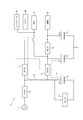
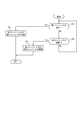
- FIG. 1 is a block diagram of a power supply system 1 according to the first embodiment.
- the solid line connecting the blocks indicates the flow of power.
- broken lines connecting the blocks indicate the flow of control.
- the power supply system 1 is mounted on a vehicle such as a hybrid vehicle or an electric vehicle.
- the power supply system 1 is connected to the AC power supply 2 when charging a first battery 21 described later.
- the AC power supply 2 can be provided in a house, a charging stand, or the like.
- AC power supply 2 may be a commercial AC power supply.
- the AC power supply 2 may be a three-phase type AC power supply.
- the AC power supply 2 may be a single-phase three-wire AC power supply or a single-phase two-wire AC power supply.
- the AC power supply 2 can supply an AC voltage in a range of, for example, 85V to 265V.
- the power supply system 1 includes a first converter 11, a second converter 12, and a third converter 13, which are connected in a loop. Further, the power supply system 1 includes a first battery 21, a second battery 22, a third battery 23, a motor 31, an accessory 32, an electronic control unit (ECU: Electronic Control Unit) 33, a memory 40, , A controller 41. In addition, the power supply system 1 may include a fourth converter 14.
- ⁇ In the power supply system 1 shown in FIG. 1, three converters of a first converter 11, a second converter 12, and a third converter 13 are connected in a loop. However, in the power supply system 1, for example, two converters may be connected in a loop or four or more converters may be connected in a loop according to the number of batteries.
- the nominal voltage of the first battery 21 is a high voltage in the range of, for example, 250 V to 450 V (hereinafter, referred to as “HV”).
- the nominal voltage of the first battery 21 may be any voltage according to the drive voltage of the motor 31.
- the nominal voltage of the second battery 22 is assumed to be 48V.
- the nominal voltage may be any voltage according to the drive voltage of the accessory 32.
- the nominal voltage of the third battery 23 is assumed to be 12V.
- the nominal voltage of the third battery 23 may be any voltage according to the drive voltage of the ECU 33, as long as the nominal voltage is lower than the nominal voltage of the second battery 22.
- the first converter 11 may include a switching element, an inductor, and the like.
- the first converter 11 is capable of bidirectional power conversion.
- the first converter 11 is, for example, a bidirectional DC-DC converter.
- the first converter 11 is capable of bidirectional power conversion between the first battery 21 and the second battery 22.
- the first converter 11 reduces the voltage HV supplied from the first battery 21 to a voltage suitable for charging the second battery 22, and converts the reduced DC voltage to the second voltage. Supply to battery 22.
- the first converter 11 reduces the voltage HV supplied from the first battery 21 to a voltage suitable for driving the auxiliary device 32 based on the control of the controller 41, and 32.
- the first converter 11 boosts the voltage 48 V supplied from the second battery 22 to a voltage suitable for driving the motor 31 and supplies the boosted DC voltage to the motor 31 based on the control of the controller 41. I do.
- the second converter 12 may include a switching element, an inductor, and the like.
- the second converter 12 is capable of bidirectional power conversion.
- the second converter 12 is, for example, a bidirectional DC-DC converter.
- the second converter 12 is capable of bidirectional power conversion between the second battery 22 and the third battery 23.
- the second converter 12 reduces the voltage of 48V supplied from the second battery 22 to a voltage suitable for charging the third battery 23, and converts the reduced DC voltage to the third voltage.
- the battery 23 is supplied.
- the second converter 12 boosts the voltage 12V supplied from the third battery 23 to a voltage suitable for charging the second battery 22, and converts the boosted DC voltage to the second voltage. Supply to battery 22.
- the second converter 12 reduces the voltage of 48 V supplied from the second battery 22 to a voltage suitable for driving the ECU 33 and supplies the reduced DC voltage to the ECU 33.
- the third converter 13 may be configured to include a switching element, an inductor, and the like.
- the third converter 13 is capable of bidirectional power conversion.
- the third converter 13 is, for example, a bidirectional DC-DC converter.
- the third converter 13 is capable of bidirectional power conversion between the first battery 21 and the third battery 23.
- the third converter 13 reduces the voltage HV supplied from the first battery 21 to a voltage suitable for charging the third battery 23, and reduces the DC voltage after the reduction to the third voltage.
- the battery 23 is supplied.
- the third converter 13 reduces the voltage HV supplied from the first battery 21 to a voltage suitable for driving the ECU 33 and supplies the reduced DC voltage to the ECU 33 based on the control of the controller 41.
- the third converter 13 boosts the voltage 12 V supplied from the third battery 23 to a voltage suitable for driving the motor 31 based on the control of the controller 41 and supplies the boosted DC voltage to the motor 31. I do.
- the fourth converter 14 may include a switching element, an inductor, and the like.
- the fourth converter 14 is capable of bidirectional power conversion.
- the fourth converter 14 is, for example, a bidirectional AC-DC converter.
- the fourth converter 14 converts AC power supplied from the AC power supply 2 into DC power under the control of the controller 41. Further, fourth converter 14 boosts the voltage of the converted DC power to voltage HV under the control of controller 41. The fourth converter 14 supplies the boosted DC voltage to the first battery 21.
- the first battery 21 may include a lithium ion battery.
- First battery 21 is provided between first converter 11 and third converter 13. That is, the first battery 21 is provided between the adjacent first converter 11 and third converter 13 in the first to third converters 11 to 13 connected in a loop.
- a positive terminal of the first battery 21 is connected between the first converter 11 and the third converter 13.
- the first battery 21 and the motor 31 are insulated from the outside.
- the first battery 21 is charged by the electric power supplied from the AC power supply 2 via the fourth converter 14, for example.
- the first battery 21 can supply DC power to at least one of the first converter 11, the third converter 13, and the motor 31 by discharging the charged power.
- the first battery 21 is used to supply electric power to the motor 31. Therefore, the nominal capacity of the first battery 21 is larger than the nominal capacity of the second battery 22 and the nominal capacity of the third battery. Therefore, in the power supply system 1, the first battery 21 is charged by the power from the AC power supply 2. Next, the electric power charged in the first battery 21 is discharged to charge the second battery 22 and the third battery 23 as described later.
- the second battery 22 may include a lithium ion battery.
- the second battery 22 is provided between the first converter 11 and the second converter 12. That is, the second battery 22 is provided between the adjacent first converter 11 and second converter 12 in the first to third converters 13 to 13 connected in a loop.
- the positive terminal of the second battery is connected between the first converter 11 and the second converter 12.
- the negative terminal of the second battery 22 is connected to a housing of the vehicle on which the power supply system 1 is mounted.
- the nominal voltage of the second battery 22 is lower than the nominal voltage of the first battery 21.
- the second battery 22 is charged by the electric power supplied from the first battery 21 via, for example, the first converter 11.
- the second battery 22 can supply DC power to at least one of the first converter 11, the second converter 12, and the accessory 32 by discharging the charged power.
- the third battery 23 may include a lithium ion battery.
- Third battery 23 is provided between second converter 12 and third converter 13. That is, the third battery 23 is provided between the adjacent second converter 12 and third converter 13 in the first to third converters 11 to 13 connected in a loop.
- a positive terminal of the third battery 23 is connected between the second converter 12 and the third converter 13.
- the negative terminal of the third battery 23 is connected to a housing of the vehicle on which the power supply system 1 is mounted.
- the nominal voltage of the third battery 23 is lower than the nominal voltage of the second battery 22.
- the third battery 23 is charged by the electric power supplied from the first battery 21 via, for example, the third converter 13.
- the third battery 23 can supply DC power to at least one of the second converter 12, the third converter 13, and the ECU 33 by discharging the charged power.
- the motor 31 generates a rotational driving force by the electric power supplied from the first battery 21.
- the rotational driving force generated by the motor 31 is transmitted to tires of a vehicle on which the power supply system 1 is mounted.
- the vehicle equipped with the power supply system 1 travels by transmitting rotational driving force to tires.
- the motor 31 may be an HEV motor or an EV motor.
- the auxiliary device 32 is driven by the electric power supplied from the second battery 22.
- one accessory 32 is connected to the second battery 22, but a plurality of accessories 32 may be connected to the second battery 22.
- the accessory 32 may be various devices provided in a vehicle on which the power supply system 1 is mounted.
- the accessory 32 may be an electric power steering, an electric suspension, a sensor for automatic driving, an electric actuator, or the like.
- the ECU 33 is driven by electric power supplied from the third battery 23.
- one ECU 33 is connected to the third battery 23, but a plurality of ECUs 33 may be connected to the third battery 23.
- the ECU 33 may be a control unit that controls the motor 31 or a control unit that controls devices included in the accessory 32.
- the memory 40 is connected to the controller 41.
- the memory 40 stores information obtained from the controller 41.
- the memory 40 may function as a working memory of the controller 41.
- the memory 40 may store a program executed by the controller 41.
- the memory 40 is formed of, for example, a semiconductor memory, but is not limited thereto, and may be formed of a magnetic storage medium or may be formed of another storage medium.
- the memory 40 may be included as a part of the controller 41.
- the controller 41 may be configured by a processor such as a CPU (Central Processing Unit) that executes a program defining a control procedure.
- the controller 41 may be a type of the ECU 33.
- the controller 41 can control the first converter 11, the second converter 12, the third converter 13, and the fourth converter 14.
- the controller 41 controls the first converter 11 and the like by outputting a control signal to the first converter 11 and the like.
- the controller 41 may be able to detect an abnormality of the first battery 21, the second battery 22, and the third battery 23.
- the controller 41 detects that the first battery 21 is abnormal.
- the controller 41 may detect the failure of the first battery 21 by using a BMS (Battery Management System) that monitors each cell voltage and the like included in the first battery 21.
- BMS Battery Management System
- the controller 41 detects that the second battery 22 is abnormal.
- the controller 41 detects that the third battery 23 is abnormal.
- the controller 41 detects that the first battery 21 is abnormal when the terminal of the first battery 21 is opened from the first converter 11 or the like and when the terminal of the first battery 21 is short-circuited.
- An open terminal is also referred to as an “open terminal”.
- a short-circuited terminal is also called a “short terminal”.
- the controller 41 may detect the open terminal and the short terminal in the first battery 21 by monitoring the voltage between the terminals of the first battery 21.
- the controller 41 detects that the second battery 22 is abnormal.
- the controller 41 detects that the third battery 23 is abnormal.
- the controller 41 may be able to detect an abnormality of the first converter 11, the second converter 12, and the third converter 13.
- the controller 41 detects that the first converter 11 is abnormal.
- the controller 41 may detect the abnormality of the first converter 11 by monitoring the output of the first converter 11.
- the controller 41 detects that the second converter 12 is abnormal.
- the controller 41 detects that the third converter 13 is abnormal.
- the controller 41 controls the fourth converter 14 by outputting a control signal to the fourth converter 14 while the power supply system 1 is connected to the AC power supply 2, and controls the first battery by the power from the AC power supply 2. Charge 21.
- the controller 41 controls the first converter 11 and the third converter 13, for example, while the vehicle equipped with the power supply system 1 is running, so that the power supplied to the first battery 21 is converted into the second battery 22 and the third battery 23.
- the power paths at this time are the path P1 and the path P2 shown in FIG.
- the path P1 is a path of power flowing from the first battery 21 to the second battery 22 via the first converter 11.
- the path P2 is a path of power flowing from the first battery 21 to the third battery 23 via the third converter 13.
- the second battery 22 is charged, and it becomes possible to supply electric power to the auxiliary device 32. Further, by such control, the third battery 23 is charged, and it becomes possible to supply electric power to the ECU 33 and the controller 41.
- the controller 41 When detecting an abnormality in the first battery 21, the controller 41 disconnects the first battery 21 that has detected the abnormality from other circuit elements by means such as a relay. That is, the controller 41 separates the failed first battery 21 from other circuit elements. Thereafter, the controller 41 controls the first converter 11 to supply the electric power charged in the second battery 22 to the motor 31 as a load connected to the first battery 21.
- the power path at this time is the path P3 shown in FIG.
- the path P3 is a path for electric power flowing from the second battery 22 to the motor 31 via the first converter 11.
- the motor 31 can continue to be driven for a while by the power supplied from the second battery 22.
- the vehicle on which the power supply system 1 is mounted can continue driving the motor 31 for a while, for example, even if an abnormality occurs in the first battery 21 during traveling.
- the vehicle can stop after traveling to a safe position such as the side of a road.
- the controller 41 controls the third converter 13 so that the electric power charged in the third battery 23 is connected to the first battery 21. It may be supplied to the motor 31 as a load.
- the power path at this time is the path P4 shown in FIG.
- the path P4 is a path of electric power flowing from the third battery 23 to the motor 31 via the third converter 13.
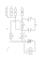
- the controller 41 When detecting an abnormality in the second battery 22, the controller 41 disconnects the second battery 22 that has detected the abnormality from other circuit elements by means such as a relay. That is, the controller 41 separates the failed second battery 22 from other circuit elements. After that, the controller 41 controls the first converter 11 to supply the electric power charged in the first battery 21 to the accessory 32 as a load connected to the second battery 22.
- the power path at this time is the path P5 shown in FIG.
- the path P5 is a path for electric power flowing from the first battery 21 to the accessory 32 via the first converter 11.
- the auxiliary device 32 can continue to be driven by the electric power from the first battery 21. That is, the vehicle equipped with the power supply system 1 can drive the accessory 32 even if an abnormality occurs in the second battery 22 during traveling, for example.
- the controller 41 may control the second converter 12 and the third converter 13 to supply the power charged in the first battery 21 to the auxiliary device 32 as a load connected to the second battery 22.
- the controller 41 detects the abnormality of the first converter 11 in addition to the abnormality of the second battery 22, the controller 41 controls the second converter 12 and the third converter 13 to supplement the power from the first battery 21. Machine 32.
- the power path at this time is the path P6 shown in FIG.
- the path P6 is a path of electric power flowing from the first battery 21 to the auxiliary device 32 via the third converter 13 and the second converter 12.
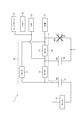
- the controller 41 When detecting an abnormality of the third battery 23, the controller 41 disconnects the third battery 23 that has detected the abnormality from other circuit elements by means such as a relay. That is, the controller 41 separates the failed third battery 23 from other circuit elements. Thereafter, the controller 41 controls the third converter 13 to supply the electric power charged in the first battery 21 to the ECU 33 as a load connected to the third battery 23 and the controller 41.
- the power path at this time is the path P7 shown in FIG.
- the path P7 is a path of electric power flowing from the first battery 21 to the ECU 33 and the like via the third converter 13.
- the ECU 33 and the like can continue to be driven by the electric power from the first battery 21. That is, the vehicle equipped with the power supply system 1 can continue to drive the ECU 33 and the like even if an abnormality occurs in the third battery 23 during traveling, for example.
- the controller 41 controls the second converter 12 to output the electric power charged in the second battery 22 to the third battery 23.
- the load may be supplied to the ECU 33 as a load connected to the ECU 23.
- the power path at this time is the path P8 shown in FIG.
- the path P8 is a path for electric power flowing from the second battery 22 to the ECU 33 and the like via the second converter 12.
- the controller 41 When detecting an abnormality in the first converter 11, the controller 41 disconnects the first converter 11 that has detected the abnormality from other circuit elements by means such as a relay. That is, the controller 41 separates the failed first converter 11 from other circuit elements.
- the controller 41 controls the second converter 12 and the third converter 13 to supply the electric power charged in the first battery 21 to the second battery 22 and the third battery 23.
- the power path at this time is the path P9 shown in FIG.
- the path P9 is a path for power flowing from the first battery 21 to the third battery 23 via the third converter 13, and from the first battery 21 to the second battery 22 via the third converter 13 and the second converter 12. This is the path of the flowing power.
- the second battery 22 and the third battery 23 can be charged by the electric power from the first battery 21.
- the auxiliary device 32 can be continuously driven by the electric power supplied from the second battery 22.
- the ECU 33 and the controller 41 can continue to be driven by the electric power supplied from the third battery 23.
- the controller 41 When detecting an abnormality in the third converter 13, the controller 41 disconnects the third converter 13 that has detected the abnormality from other circuit elements by means such as a relay. That is, the controller 41 separates the failed third converter 13 from other circuit elements.
- the controller 41 controls the first converter 11 and the second converter 12 to supply the power charged in the first battery 21 to the second battery 22 and the third battery 23.
- the power path at this time is the path P10 shown in FIG.
- the path P10 is a path for power flowing from the first battery 21 to the second battery 22 via the first converter 11, and a path from the first battery 21 to the third battery 23 via the first converter 11 and the second converter 12. This is the path of the flowing power.
- the second battery 22 and the third battery 23 can be charged by the electric power from the first battery 21.
- the auxiliary device 32 can be continuously driven by the electric power supplied from the second battery 22.
- the ECU 33 and the controller 41 can continue to be driven by the electric power supplied from the third battery 23.
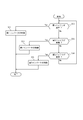
- FIG. 7 is a flowchart illustrating an example of the operation of the power supply system 1 according to the first embodiment. For example, when the vehicle equipped with the power supply system 1 starts running, the controller 41 starts the processing illustrated in FIG. When the vehicle equipped with the power supply system 1 stops running, the controller 41 ends the process illustrated in FIG.
- Step S10 determines whether the first battery 21 is abnormal.
- step S10: Yes determines that the first battery 21 is abnormal
- step S11: No determines that the first battery 21 is abnormal
- step S12: No determines that the first battery 21 is abnormal
- step S11 the controller 41 controls the first converter 11 to supply the electric power charged in the second battery 22 to the motor 31 as a load connected to the first battery 21 (see FIG. Path P3).
- step S12 the controller 41 determines whether the second battery 22 is abnormal.
- step S12: Yes the process proceeds to step S13.
- step S12: No the process proceeds to step S14.
- step S13 the controller 41 controls the first converter 11 to supply the power charged in the first battery 21 to the accessory 32 as a load connected to the second battery 22 (see: Route P5 in FIG. 3).
- step S14 the controller 41 determines whether the third battery 23 is abnormal.
- step S14: Yes the process proceeds to step S15.
- step S14: No the process returns to step S10.
- step S15 the controller 41 controls the third converter 13 to supply the power charged in the first battery 21 to the ECU 33 as a load connected to the third battery 23 and the controller 41 (see : Path P7 in FIG. 4).
- step S11 the controller 41 controls the third converter 13 to supply the electric power charged in the third battery 23 to the motor 31 as a load connected to the first battery 21. Good (see: path P4 in FIG. 2).
- the controller 41 controls the second converter 12 and the third converter 13 to use the power charged in the first battery 21 as a load connected to the second battery 22. It may be supplied to the auxiliary machine 32 (see the route P6 in FIG. 3).
- step S15 the controller 41 controls the second converter 12 to supply the electric power charged in the second battery 22 to the ECU 33 or the like as a load connected to the third battery 23. Good (see: path P8 in FIG. 4).
- FIG. 8 is a flowchart illustrating another example of the operation of the power supply system 1 according to the first embodiment.
- the controller 41 starts the process illustrated in FIG.
- the controller 41 ends the processing illustrated in FIG. Note that the controller 41 may execute the processing shown in FIG. 8 in parallel with the processing shown in FIG.
- Step S20 determines whether or not the first converter 11 is abnormal.
- step S20: Yes determines that the first converter 11 is abnormal
- step S21 determines whether or not the first converter 11 is abnormal
- step S21 determines whether or not the first converter 11 is abnormal
- step S22 determines whether or not the first converter 11 is abnormal
- step S21 the controller 41 controls the second converter 12 and the third converter 13 to supply the power charged in the first battery 21 to the second battery 22 and the third battery 23 (see: Path P9 in FIG. 5).
- step S22 the controller 41 determines whether the third converter 13 is abnormal.
- step S22: Yes the process proceeds to step S23.
- step S22: No the controller 41 returns to the processing of step S20.
- step S23 the controller 41 controls the first converter 11 and the second converter 12 to supply the power charged in the first battery 21 to the second battery 22 and the third battery 23 (see: Route P10 in FIG. 6).
- the first converter 11, the second converter 12, and the third converter 13 are connected in a loop. Further, the first battery 21 is provided between the first converter 11 and the third converter 13, the second battery 22 is provided between the first converter 11 and the second converter 12, and the third battery 23 is provided It is provided between the second converter 12 and the third converter. With such a configuration, it is possible to continue to supply power to the load even if any of the first converter 11 and the like and the first battery 21 and the like included in the power supply system 1 have an abnormality. Therefore, according to the first embodiment, the power supply system 1 with improved reliability can be provided.
- FIG. 9 is a circuit diagram of a DC-DC converter according to the second embodiment.
- FIG. 9 is a circuit diagram of the converter 10.
- Converter 10 is connected between battery 20A and battery 20B.
- the nominal voltage of battery 20A is lower than the nominal voltage of battery 20B. That is, when the converter 10 is the first converter 11, the battery 20A becomes the second battery 22 shown in FIG. 1, and the battery 20B becomes the first battery 21 shown in FIG.
- converter 10 is second converter 12
- battery 20A becomes third battery 23 shown in FIG. 1 and battery 20B becomes second battery 22 shown in FIG.
- converter 10 is third converter 13
- battery 20A becomes third battery 23 shown in FIG. 1 and battery 20B becomes first battery 21 shown in FIG.
- the converter 10 includes a drive circuit 50, switching circuits 51A and 51B, smoothing capacitors 52A and 52B, and a transformer 60. Further, converter 10 may include switches 90A and 90B for disconnecting the circuit from transformer 60.
- the drive circuit 50 generates a pulse-wave drive signal for turning on and off the switching circuits 51A and 51B at a predetermined timing based on the control signal from the controller 41 shown in FIG.
- the frequency of the drive signal that is a pulse wave is also described as “drive frequency”.
- the drive circuit 50 outputs the generated drive signal to the switching circuits 51A and 51B.
- the drive circuit 50 generates a control signal for controlling the switches 90A and 90B to be turned on and off based on the control signal from the controller 41 shown in FIG.
- the drive circuit 50 outputs the generated control signal to the switches 90A and 90B.
- the controller 41 turns on 90A and 90B when operating the converter 10, and turns off at other times.
- the switching circuit 51A is connected between the battery 20A and the transformer 60.
- the switching circuit 51A is a full-bridge circuit. When converter 10 boosts the voltage on battery 20A side to the voltage on battery 20B side, switching circuit 51A is driven by a drive signal from drive circuit 50.
- the switching circuit 51A has switching elements Q1A, Q2A, QA3, and Q4A.
- the switching elements Q1A to Q4A may be N-type MOSFETs.
- the switching elements Q1A to Q4A may be power MOSFETs.
- the switching elements Q1A to Q4A are not limited to MOSFETs.
- switching elements Q1A to Q4A may be bipolar transistors or IGBTs (Insulated Gate Bipolar Transistor).
- the drains of the switching elements Q1A and Q3A are connected to the positive terminal of the battery 20A.
- the sources of the switching elements Q2A and Q4A are connected to the negative terminal of the battery 20A.
- the source of the switching element Q1A and the drain of the switching element Q2A are connected to one end of the winding 70 of the transformer 60.
- the source of the switching element Q3A and the drain of the switching element Q4A are connected to the other end of the winding 70 of the transformer 60.
- the drive signal from the drive circuit 50 is input to the gates of the switching elements Q1A to Q4A.
- switching elements Q1A and Q4A are turned on by the input of the drive signal, switching elements Q2A and Q3A are turned off.
- switching elements Q1A and Q4A are turned off, switching elements Q2A and Q3A are turned on.
- the switching elements Q1A and Q4A and the switching elements Q2A and Q3A alternately turn on and off at the drive frequency.
- an alternating current having the drive frequency flows through the winding 70 of the transformer 60.
- an induced electromotive force is generated in the winding 80 of the transformer 60.
- the switching circuit 51B is connected between the battery 20B and the transformer 60.
- the switching circuit 51B is a full-bridge type circuit. When converter 10 steps down the voltage of battery 20B to the voltage of battery 20A, switching circuit 51B is driven by a drive signal from drive circuit 50.
- the switching circuit 51B has switching elements Q1B, Q2B, Q3B, Q4B.
- the switching elements Q1B to Q4B may be N-type MOSFETs.
- the switching elements Q1B to Q4B may be power MOSFETs.
- the switching elements Q1B to Q4B are not limited to MOSFETs.
- switching elements Q1B-Q4B may be bipolar transistors or IGBTs.
- the drains of the switching elements Q1B and Q3B are connected to the positive terminal of the battery 20B.
- the sources of the switching elements Q2B and Q4B are connected to the negative terminal of the battery 20B.
- the source of the switching element Q1B and the drain of the switching element Q2B are connected to one end of the winding 80 of the transformer 60.
- the source of the switching element Q3B and the drain of the switching element Q4B are connected to the other end of the winding 80 of the transformer 60.
- the drive signal from the drive circuit 50 is input to the gates of the switching elements Q1B to Q4B.
- switching elements Q1B and Q4B are turned on by the input of the drive signal, switching elements Q2B and Q3B are turned off.
- switching elements Q1B and Q4B are turned off, switching elements Q2B and Q3B are turned on.
- the switching elements Q1B and Q4B and the switching elements Q2B and Q3B are alternately turned on and off at the drive frequency. Since the switching elements Q1B and Q4B and the switching elements Q2B and Q3B are alternately turned on and off at the drive frequency, an alternating current having the drive frequency flows through the winding 80 of the transformer 60.
- an induced electromotive force is generated in the winding 70 of the transformer 60.
- the smoothing capacitor 52A is provided between the battery 20A and the switching circuit 51A.
- the smoothing capacitor 52A smoothes the voltage between the switching circuit 51A and the battery 20A.
- the smoothing capacitor 52B is provided between the battery 20B and the switching circuit 51B. Smoothing capacitor 52B smoothes the voltage between switching circuit 51B and battery 20B.
- the transformer 60 is an insulating transformer.
- the transformer 60 may be a planar transformer.
- the transformer 60 is not limited to a planar type transformer.
- the transformer 60 may be a transformer including a bobbin and a conductive line.
- the transformer 60 of the first converter 11 is referred to as a "transformer 61".
- the transformer 60 of the second converter 12 is referred to as a “transformer 62”.
- the transformer 60 of the third converter 13 is described as “transformer 63”.
- the transformer 60 has a core 65, a winding 70, and a winding 80.
- the transformers 61, 62, and 63 share the core 65. This configuration will be described later with reference to FIGS.
- the winding 70 is formed as a conductor pattern when the transformer 60 is a planar type transformer. Winding 70 is also referred to as “primary winding” when converter 10 boosts the voltage on battery 20A side to the voltage on battery 20B side. When converter 10 steps down the voltage on battery 20B side to the voltage on battery 20A side, winding 70 is also referred to as “secondary winding”. The number of turns of the winding 70 and the number of turns of the winding 80 are appropriately set based on the voltage at which the converter 10 steps up and steps down.
- windings 70 of the transformer 61 that is, the first converter 11
- windings 70 of the transformer 62 that is, the second converter 12
- winding 72 the winding 70 included in the transformer 63
- winding 73 the winding 70 included in the transformer 63
- winding 80 is formed as a conductor pattern when the transformer 60 is a planar type transformer. Winding 80 is also referred to as “secondary winding” when converter 10 boosts the voltage on battery 20A side to the voltage on battery 20B side. When converter 10 steps down the voltage on battery 20B side to the voltage on battery 20A side, winding 70 is also referred to as “primary winding”.
- windings 80 included in the transformer 61 are described as “windings 81”.
- the winding 80 of the transformer 62 (that is, of the second converter 12) is referred to as “winding 82”.
- the winding 80 of the transformer 63 (that is, the third converter 13) is referred to as “winding 83”.
- the switches 90A, 90B may be N-type MOSFETs, like the switching element Q1A.
- the switches 90A and 90B may be power MOSFETs.
- the switches 90A and 90B are not limited to MOSFETs.
- switches 90A and 90B may be bipolar transistors or IGBTs.
- switches 90A and 90B included in each of the first converter 11, the second converter 12, and the third converter 13 are distinguished, the switches 90A and 90B included in the first converter 11 are referred to as “switch 91A” and “switch 91B”. ".
- the switches 90A and 90B included in the second converter 12 are referred to as “switch 92A” and “switch 92B”.
- the switches 90A and 90B included in the third converter 13 are described as “switch 93A” and “switch 93B”.
- the switch 90A is provided between the battery 20A and the switching circuit 51A.
- the switch 90A is provided between the negative terminal of the battery 20A and the source of the switching element Q2A of the switching circuit 51A.
- the switch 90B is provided between the battery 20B and the switching circuit 51B.
- the switch 90B is provided between the negative terminal of the battery 20B and the source of the switching element Q4B of the switching circuit 51B.
- the switches 90A and 90B disconnect the transformer 60 from other components based on a control signal from the drive circuit 50.
- the switch 90A disconnects the connection between the transformer 60 and the switching circuit 51A from the smoothing capacitor 52A and the battery 20A by turning off based on a control signal from the drive circuit 50.
- the switch 90B is turned off based on a control signal from the drive circuit 50 to disconnect the connection between the transformer 60 and the switching circuit 51B and the smoothing capacitor 52B and the battery 20B.
- the switch 90A may be provided between the positive terminal of the battery 20A and the drain of the switching element Q1A of the switching circuit 51A.
- the switch 90B may be provided between the positive terminal of the battery 20B and the drain of the switching element Q3B of the switching circuit 51B.
- the switches 90A and 90B may be P-type MOSFETs.
- FIG. 10 is a circuit diagram of the AC-DC converter according to the second embodiment.
- FIG. 10 is a circuit diagram of the fourth converter 14.
- Fourth converter 14 includes converter 10 and rectifier circuit 15.
- the converter 10 is connected between the rectifier circuit 15 and the first battery 21.
- Converter 10 boosts the voltage from rectifier circuit 15 to a predetermined voltage and then supplies it to first battery 21.
- the transformer 60 included in the converter 10 of the fourth converter 14 is also described as “transformer 64”.
- the winding 70 of the transformer 64 is also described as “winding 74”.
- the winding 80 of the transformer 64 is also described as “winding 84”.
- the switches 90A and 90B included in the converter 10 of the fourth converter 14 are also referred to as “switches 94A” and “switches 94B”.
- the transformer 64 may be configured by sharing the core 65 with the transformers 61, 62, 63 described above. This configuration will be described later with reference to FIGS.
- the rectifier circuit 15 may include a switching element and an inductor.
- the rectifier circuit 15 may be a three-phase full-wave rectification circuit or a three-phase half-wave rectification circuit.
- the rectifier circuit 15 can be connected to the AC power supply 2.
- the rectifier circuit 15 converts an AC current from the AC power supply 2 into a DC current by rectifying the AC current.
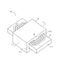
- FIG. 11 is a perspective view of a planar transformer according to the second embodiment.
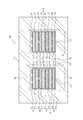
- FIG. 12 is a cross-sectional view of the planar transformer taken along line LL shown in FIG. In FIG. 12, the magnetic flux of the closed magnetic path formed inside the core 65 is indicated by a broken line.
- the planar transformer 100 includes a core 65, windings 71, 72, 73, 74, windings 81, 82, 83, 84, and a substrate 110.
- the core 65 may be made of a magnetic material such as ferrite.
- the core 65 may be configured by combining a pair of E-shaped cores having an E-shaped cross-section such that three legs face each other. As shown in FIG. 12, the core 65 includes a middle leg 66, side legs 67-1 and 67-2, an upper surface 68, and a lower surface 69.
- the middle leg portion 66 is inserted into the opening located at the center of the windings 71 to 74 and the opening located at the center of the windings 81 to 84.
- the windings 71 to 74 and the windings 81 to 84 are wound around the middle leg 66.
- the middle leg 66 may be provided with a gap 66a.
- the side leg 67-1 is located on one outside of the substrate 110 as shown in FIG.
- the side leg 67-2 is located outside the other side of the substrate 110 as shown in FIG.
- the upper surface portion 68 connects the upper portion of the middle leg portion 66 and the upper portions of the side leg portions 67-1, 67-2 as shown in FIG.
- the lower surface portion 69 connects the lower portion of the middle leg portion 66 and the lower portions of the side leg portions 67-1, 67-2, as shown in FIG.
- the windings 71 to 74 and 81 to 84 are conductor patterns formed using a conductor such as copper.
- the windings 71 to 74 and 81 to 84 have openings at their centers. As described above, the windings 71 and 81 are included in the transformer 61. Further, the windings 72 and 82 are included in the transformer 62. The windings 73 and 83 are included in the transformer 63. The windings 74 and 84 are included in the transformer 64.
- the substrate 110 includes an insulating material.
- the substrate 110 includes substrates 111, 112, 113, 114, 115, 116, 117 and 118 as shown in FIG.
- the winding 81 is arranged on the upper surface of the substrate 111.
- the winding 71 is arranged on the lower surface of the substrate 111.
- the winding 82 is arranged on the upper surface of the substrate 112.
- the winding 72 is arranged on the lower surface of the substrate 112.
- the winding 83 is arranged on the upper surface of the substrate 113.
- the winding 73 is arranged on the lower surface of the substrate 113.
- the winding 84 is arranged on the upper surface of the substrate 114.
- the winding 74 is arranged on the lower surface of the substrate 114.
- the substrate 115 is disposed between the winding 71 and the winding 82.
- the board 116 is arranged between the winding 72 and the winding 83.
- the board 117 is arranged between the winding 73 and the winding 84.
- each of the transformers 61 to 64 of the first converter 11, the second converter 12, the third converter 13, and the fourth converter 14 can be configured to share the core 65.
- the first converter 11, the second converter 12, the third converter 13, and the fourth converter 14 can be downsized. Therefore, the power supply system 1 can be downsized.
- the transformers 61 to 64 as planar type transformers, the first converter 11, the second converter 12, the third converter 13, and the fourth converter 14 can be further reduced in size.
- Bmax is the saturation magnetic flux density of the core 65.
- Bmax is a value corresponding to the magnetic characteristics of the core 65. That is, Bmax is a value corresponding to the magnetic material forming the core 65.
- A is the cross-sectional area of the middle leg 66 shown in FIG.
- Magnetic flux ⁇ is magnetic flux ⁇ generated in middle leg portion 66 when converter 10 shown in FIG. 9 is driven.
- the magnetic flux ⁇ is calculated by the following equations (2) and (3).
- V is a voltage applied to the core 65 when the converter 10 shown in FIG. 9 is driven.
- n is the number of turns of the winding 80 shown in FIG. D is the duty of the pulse wave (drive signal) for turning on and off the switching elements Q1A to Q4A shown in FIG. D may be 0.5 in a bidirectional system such as converter 10 shown in FIG. T is a period of a pulse wave (drive signal) for turning on and off the switching elements Q1A to Q4A shown in FIG. T is also called a PWM (Pulse Wide Modulation) cycle.
- the driving frequency of the first converter 11 is set to be higher than the driving frequencies of the second converter 12, the third converter 13, and the fourth converter 14. Further, the driving frequency of the first converter 11 is set so as to satisfy Expression (1).
- the drive frequency f of the first converter 11 is determined according to the magnetic characteristics of the core 65. With such a configuration, magnetic saturation in the core 65 can be prevented. Further, by driving the second converter 12, the third converter 13, and the fourth converter 14 at a drive frequency lower than the drive frequency of the first converter 11, the power conversion efficiency of the second converter 12 and the like can be improved. it can.
- controller processing In the second embodiment, the controller 41 shown in FIG. 1 controls the switches 91A to 94A and 91B to 94B so that the first converter 11, the second converter 12, the third converter 13, and the fourth converter 14 are not driven at the same time. Control.
- the controller 41 shown in FIG. 1 drives the first converter 11 among the first converter 11, the second converter 12, the third converter 13, and the fourth converter 14. That is, of the first converter 11, the second converter 12, the third converter 13, and the fourth converter 14, the second converter 12, the third converter 13, and the fourth converter 14 are converters that are not controlled by the controller 41. Shall be.
- the controller 41 controls so as not to drive the second converter 12, the third converter 13, and the fourth converter 14.
- the controller 41 shown in FIG. 1 outputs a control signal to the drive circuit 50 of the first converter 11 shown in FIG. 9 so that the switches 91A and 91B are turned on.
- the controller 41 outputs a control signal to the drive circuit 50 of each of the second converter 12, the third converter 13, and the fourth converter 14 shown in FIG. 9 so that the switches 92A to 94A and 92B to 94B are turned off. I do.
- the transformer 61 is connected to other components such as the smoothing capacitor 52A.
- the transformers 62 to 64 are separated from other components.
- the second converter 12, the third converter 13, and the fourth converter 14, which are not driven it is possible to prevent an unintended current from leaking from the transformers 62 to 64 to other components.
- switches 90A and 90B are provided is not limited to the configuration illustrated in FIG.
- a configuration as shown in FIG. 13 may be used.
- FIG. 13 is a circuit diagram of a DC-DC converter according to another example of the second embodiment.
- FIG. 13 shows a part of the configuration shown in FIG.
- the same DC-DC converter can be used for the first converter 11a, the second converter 12a, the third converter 13a, and the fourth converter 14a.
- the first converter 11a will be described as an example.
- the first converter 11a has switches 121A and 122A between the winding 71 and the switching circuit 51A.
- the first converter 11a has switches 121B and 122B between the winding 81 and the switching circuit 51B.
- the switches 121A and 122A may be configured to include a relay circuit.
- the switch 121A is provided between one end of the winding 71 and the source of the switching element Q1A and the drain of the switching element Q2A of the switching circuit 51A shown in FIG.
- the switch 122A is provided between the other end of the winding 71 and the source of the switching element Q3A and the drain of the switching element Q4A of the switching circuit 51A shown in FIG.
- the switches 121A and 122A switch between conduction and interruption based on a control signal from the controller 41 shown in FIG.
- the switches 121B and 122B may be configured to include a relay circuit.
- the switch 121B is provided between one end of the winding 81 and the source of the switching element Q1B and the drain of the switching element Q2B of the switching circuit 51B shown in FIG.
- the switch 122B is provided between the other end of the winding 81 and the source of the switching element Q3B and the drain of the switching element Q4B of the switching circuit 51B shown in FIG.
- the switches 121B and 122B switch between conduction and interruption based on a control signal from the controller 41 shown in FIG.
- the transformers 61 to 64 have been described as being configured to share the core 65 as shown in FIGS.
- the transformers 61 to 63 may be configured to share the core 65.
- REFERENCE SIGNS LIST 1 power supply system 2 AC power supply 10 converter 11, 11a first converter 12, 12a second converter 13, 13a third converter 14, 14a fourth converter 15 rectifier circuit 20A, 20B battery 21 first battery 22 second battery 23 third Battery 31 Motor (load) 32 Auxiliary equipment (load) 33 ECU (load) Reference Signs List 40 memory 41 controller 50 drive circuit 51A, 51B switching circuit 52A, 52B smoothing capacitor 60, 61 to 64 transformer 65 core 66 middle leg 66a gap 67-1, 67-2 side leg 68 upper surface portion 69 lower surface portion 70 to 74 , 80 to 84 Windings 90A to 94A, 90B to 94B Switch 100 Planar type transformer 110 to 117 Board 121A, 121B, 122A, 122B Switch P1 to P10 Path Q1A to Q4A, Q1B to Q4B Switching element
Abstract
信頼性が向上された電源システムを提供する。電源システム1は、ループ状に接続された、第1コンバータ11と、第2コンバータ12と、第3コンバータ13とを備える。さらに、電源システム1は、第1バッテリ21と、第2バッテリ22と、第3バッテリ23と、コントローラ41とを備える。第1コンバータ11、第2コンバータ12及び第3コンバータ13は、双方向の電力変換が可能である。第1バッテリ21は、隣接する第1コンバータ11と第3コンバータ13との間に設けられている。第2バッテリ22は、隣接する第1コンバータ11と第2コンバータ12との間に設けられている。第3バッテリ23は、隣接する第2コンバータ12と第3コンバータ13との間に設けられている。電源システム1は、第1コンバータ11、第2コンバータ12及び第3コンバータ13を制御可能である。
Description
本出願は、日本国特許出願2018-160821号(2018年8月29日出願)の優先権を主張するものであり、当該出願の開示全体を、ここに参照のために取り込む。
本発明は、電源システムに関する。
近年、例えば自動車等の車両では、複数の異なる電圧で駆動状態になる多様な負荷が搭載される。このような多様な負荷に電力を供給するために、異なる電圧を供給可能な電源システムが知られている(例えば、特許文献1)。
電源システムは、例えば負荷に供給する異なる電圧に応じた、複数のバッテリを備える。このような電源システムは、例えば複数のバッテリのうちの1つのバッテリが故障すると、電力を供給できなくなる虞がある。
かかる点に鑑みてなされた本発明の目的は、信頼性が向上された、電源システムを提供することにある。
上記課題を解決するために、第1の観点に係る電源システムは、
ループ状に接続された、双方向の電力変換が可能な複数のコンバータと、
前記複数のコンバータにおいて隣接するコンバータ間に設けられている複数のバッテリと、
前記複数のコンバータを制御可能なコントローラと、
を備える。
ループ状に接続された、双方向の電力変換が可能な複数のコンバータと、
前記複数のコンバータにおいて隣接するコンバータ間に設けられている複数のバッテリと、
前記複数のコンバータを制御可能なコントローラと、
を備える。
第1の観点に係る電源システムによれば、信頼性が向上され得る。
以下、本開示の実施形態について、図面を参照して説明する。以下では、本開示の電源システムは、ハイブリット車又は電気自動車等の車両に搭載されるものとして説明する。ただし、本開示の電源システムは、電力を消費する任意の装置に搭載されてよい。
(第1実施形態)
[システム構成]
図1は、第1実施形態に係る電源システム1のブロック図である。図1において、各ブロックを結ぶ実線は、電力の流れを示す。また、図1において、各ブロックを結ぶ破線は、制御の流れを示す。
[システム構成]
図1は、第1実施形態に係る電源システム1のブロック図である。図1において、各ブロックを結ぶ実線は、電力の流れを示す。また、図1において、各ブロックを結ぶ破線は、制御の流れを示す。
電源システム1は、ハイブリット車又は電気自動車等の車両に搭載される。電源システム1は、後述の第1バッテリ21を充電する際、交流電源2に接続される。交流電源2は、住宅又は充電スタンド等に設けられ得る。交流電源2は、商用交流電源であってよい。交流電源2は、三相形式の交流電源であってよい。又は、交流電源2は、単相3線形式の交流電源であってもよいし、単相2線形式の交流電源であってもよい。交流電源2は、例えば85V~265Vの範囲の、交流電圧を供給可能である。
電源システム1は、ループ状に接続された、第1コンバータ11と、第2コンバータ12と、第3コンバータ13とを備える。さらに、電源システム1は、第1バッテリ21と、第2バッテリ22と、第3バッテリ23と、モータ31と、補機32と、電子制御ユニット(ECU:Electronic Control Unit)33と、メモリ40と、コントローラ41とを備える。加えて、電源システム1は、第4コンバータ14を備えてよい。
図1に示す電源システム1では、第1コンバータ11、第2コンバータ12及び第3コンバータ13の3つのコンバータが、ループ状に接続されている。ただし、電源システム1では、例えばバッテリの数に応じて、2つのコンバータがループ状に接続されてもよいし、4つ以上のコンバータがループ状に接続されてもよい。
以下、第1バッテリ21の公称電圧は、例えば250V~450Vの範囲の高電圧(以下、「HV」と記載する)であるものとする。ただし、第1バッテリ21の公称電圧は、モータ31の駆動電圧に応じた任意の電圧であってよい。また、第2バッテリ22の公称電圧は、48Vであるものとする。ただし、第2バッテリ22の公称電圧は、第1バッテリ21の公称電圧よりも低ければ、補機32の駆動電圧に応じた任意の電圧であってよい。また、第3バッテリ23の公称電圧は、12Vであるものとする。ただし、第3バッテリ23の公称電圧は、第2バッテリ22の公称電圧よりも低ければ、ECU33の駆動電圧に応じた任意の電圧であってよい。
第1コンバータ11は、スイッチング素子及びインダクタ等を含んで構成されてよい。第1コンバータ11は、双方向の電力変換が可能である。第1コンバータ11は、例えば、双方向のDC-DCコンバータである。第1コンバータ11は、第1バッテリ21と第2バッテリ22との間で双方向の電力変換が可能である。
例えば、第1コンバータ11は、コントローラ41の制御に基づいて、第1バッテリ21から供給される電圧HVを、第2バッテリ22の充電に適した電圧まで降圧し、降圧後の直流電圧を第2バッテリ22に供給する。又は、第1コンバータ11は、コントローラ41の制御に基づいて、第1バッテリ21から供給される電圧HVを、補機32の駆動に適した電圧まで降圧し、降圧後の直流電圧を、補機32に供給する。又は、第1コンバータ11は、コントローラ41の制御に基づいて、第2バッテリ22から供給される電圧48Vを、モータ31の駆動に適した電圧まで昇圧し、昇圧後の直流電圧をモータ31に供給する。
第2コンバータ12は、スイッチング素子及びインダクタ等を含んで構成されてよい。第2コンバータ12は、双方向の電力変換が可能である。第2コンバータ12は、例えば、双方向のDC-DCコンバータである。第2コンバータ12は、第2バッテリ22と第3バッテリ23との間で双方向の電力変換が可能である。
例えば、第2コンバータ12は、コントローラ41の制御に基づいて、第2バッテリ22から供給される電圧48Vを、第3バッテリ23の充電に適した電圧まで降圧し、降圧後の直流電圧を第3バッテリ23に供給する。又は、第2コンバータ12は、コントローラ41の制御に基づいて、第3バッテリ23から供給される電圧12Vを、第2バッテリ22の充電に適した電圧まで昇圧し、昇圧後の直流電圧を第2バッテリ22に供給する。又は、第2コンバータ12は、コントローラ41の制御に基づいて、第2バッテリ22から供給される48Vを、ECU33の駆動に適した電圧に降圧し、降圧後の直流電圧をECU33に供給する。
第3コンバータ13は、スイッチング素子及びインダクタ等を含んで構成されてよい。第3コンバータ13は、双方向の電力変換が可能である。第3コンバータ13は、例えば、双方向のDC-DCコンバータである。第3コンバータ13は、第1バッテリ21と第3バッテリ23との間で双方向の電力変換が可能である。
例えば、第3コンバータ13は、コントローラ41の制御に基づいて、第1バッテリ21から供給される電圧HVを、第3バッテリ23の充電に適した電圧まで降圧し、降圧後の直流電圧を第3バッテリ23に供給する。又は、第3コンバータ13は、コントローラ41の制御に基づいて、第1バッテリ21から供給される電圧HVを、ECU33の駆動に適した電圧まで降圧し、降圧後の直流電圧をECU33に供給する。又は、第3コンバータ13は、コントローラ41の制御に基づいて、第3バッテリ23から供給される電圧12Vを、モータ31の駆動に適した電圧まで昇圧し、昇圧後の直流電圧をモータ31に供給する。
第4コンバータ14は、スイッチング素子及びインダクタ等を含んで構成されてよい。第4コンバータ14は、双方向の電力変換が可能である。第4コンバータ14は、例えば、双方向のAC-DCコンバータである。
例えば、第4コンバータ14は、コントローラ41の制御に基づいて、交流電源2から供給される交流電力を直流電力に変換する。さらに、第4コンバータ14は、コントローラ41の制御に基づいて、変換した直流電力の電圧を、電圧HVまで昇圧する。第4コンバータ14は、昇圧後の直流電圧を第1バッテリ21に供給する。
第1バッテリ21は、リチウムイオンバッテリを含んで構成されてよい。第1バッテリ21は、第1コンバータ11と第3コンバータ13との間に設けられている。つまり、第1バッテリ21は、ループ状に接続されている第1コンバータ11~第3コンバータ13において、隣接する第1コンバータ11と第3コンバータ13との間に設けられている。例えば、第1バッテリ21の正極側の端子は、第1コンバータ11と第3コンバータ13との間に接続されている。第1バッテリ21とモータ31は、外部に対し絶縁される。
第1バッテリ21は、例えば第4コンバータ14を介して、交流電源2から供給される電力によって、充電される。第1バッテリ21は、充電された電力を放電することにより、直流電力を、第1コンバータ11、第3コンバータ13及びモータ31の少なくとも何れかに供給可能である。
第1バッテリ21は、モータ31に電力を供給するために用いられる。そのため、第1バッテリ21の公称容量は、第2バッテリ22の公称容量及び第3バッテリの公称容量と比べると、大きい。このため、電源システム1では、交流電源2からの電力によって第1バッテリ21を充電する。次に、第1バッテリ21に充電された電力を放電することにより、後述のように第2バッテリ22及び第3バッテリ23を充電する。
第2バッテリ22は、リチウムイオンバッテリを含んで構成されてよい。第2バッテリ22は、第1コンバータ11と第2コンバータ12との間に設けられている。つまり、第2バッテリ22は、ループ状に接続されている第1コンバータ11~第3コンバータ13において、隣接する第1コンバータ11と第2コンバータ12との間に設けられている。例えば、第2バッテリの正極側の端子は、第1コンバータ11と第2コンバータ12との間に接続されている。また、第2バッテリ22の負極側の端子は、電源システム1を搭載する車両の筐体(ボディ)に接続されている。
第2バッテリ22の公称電圧は、第1バッテリ21の公称電圧よりも低い。第2バッテリ22は、例えば第1コンバータ11を介して、第1バッテリ21から供給される電力によって、充電される。第2バッテリ22は、充電された電力を放電することにより、直流電力を、第1コンバータ11、第2コンバータ12及び補機32の少なくとも何れかに供給可能である。
第3バッテリ23は、リチウムイオンバッテリを含んで構成されてよい。第3バッテリ23は、第2コンバータ12と第3コンバータ13との間に設けられている。つまり、第3バッテリ23は、ループ状に接続されている第1コンバータ11~第3コンバータ13において、隣接する第2コンバータ12と第3コンバータ13との間に設けられている。例えば、第3バッテリ23の正極側の端子は、第2コンバータ12と第3コンバータ13との間に接続されている。また、第3バッテリ23の負極側の端子は、電源システム1を搭載する車両の筐体(ボディ)に接続されている。
第3バッテリ23の公称電圧は、第2バッテリ22の公称電圧よりも低い。第3バッテリ23は、例えば第3コンバータ13を介して、第1バッテリ21から供給される電力によって、充電される。第3バッテリ23は、充電された電力を放電することにより、直流電力を、第2コンバータ12、第3コンバータ13及びECU33の少なくとも何れかに供給可能である。
モータ31は、第1バッテリ21から供給される電力により、回転駆動力を生成する。モータ31によって生成された回転駆動力は、電源システム1を搭載する車両のタイヤに伝達される。電源システム1を搭載する車両は、タイヤに回転駆動力が伝達されることにより、走行する。モータ31は、HEV用モータ又はEV用モータであってよい。
補機32は、第2バッテリ22から供給される電力により、駆動する。図1では、1つの補機32が第2バッテリ22に接続されているが、複数の補機32が第2バッテリ22に接続されてもよい。補機32は、電源システム1が搭載される車両が備える多様な機器であってよい。例えば、補機32は、電動パワーステアリング、電動サスペンション、自動運転用のセンサ又は電動アクチュエータ等であってよい。
ECU33は、第3バッテリ23から供給される電力により、駆動する。図1では、1つのECU33が第3バッテリ23に接続されているが、複数のECU33が第3バッテリ23に接続されてもよい。ECU33は、モータ31を制御する制御ユニット、又は、補機32に含まれる機器を制御する制御ユニット等であってよい。
メモリ40は、コントローラ41に接続されている。メモリ40は、コントローラ41から取得した情報を格納する。メモリ40は、コントローラ41のワーキングメモリとして機能してよい。メモリ40は、コントローラ41が実行するプログラムを格納してよい。メモリ40は、例えば、半導体メモリで構成されるが、これには限られず、磁気記憶媒体で構成されてよいし、他の記憶媒体で構成されてよい。メモリ40は、コントローラ41の一部として含まれてよい。
コントローラ41は、制御手順を規定したプログラムを実行するCPU(Central Processing Unit)等のプロセッサで構成されてよい。コントローラ41は、ECU33の一種であってよい。
コントローラ41は、第1コンバータ11、第2コンバータ12、第3コンバータ13及び第4コンバータ14を制御可能である。例えば、コントローラ41は、第1コンバータ11等へ制御信号を出力することにより、第1コンバータ11等を制御する。
コントローラ41は、第1バッテリ21、第2バッテリ22及び第3バッテリ23の異常を検出可能であってよい。
例えば、コントローラ41は、第1バッテリ21が故障したとき、第1バッテリ21が異常であると検出する。この場合、コントローラ41は、第1バッテリ21に含まれる各セル電圧等を監視するBMS(Battery Management System)によって、第1バッテリ21の故障を検出してよい。同様に、例えば、コントローラ41は、第2バッテリ22が故障したとき、第2バッテリ22が異常であると検出する。同様に、例えば、コントローラ41は、第3バッテリ23が故障したとき、第3バッテリ23が異常であると検出する。
例えば、コントローラ41は、第1バッテリ21の端子が第1コンバータ11等から開放されたとき及び第1バッテリ21の端子が短絡したとき、第1バッテリ21が異常であると検出する。開放された端子は、「オープン端子」ともいう。また、短絡した端子は、「ショート端子」ともいう。この場合、コントローラ41は、第1バッテリ21の端子間の電圧を監視することにより、第1バッテリ21においてオープン端子及びショート端子を検出してもよい。同様に、例えば、コントローラ41は、第2バッテリ22においてオープン端子又はショート端子を検出したとき、第2バッテリ22が異常であると検出する。同様に、例えば、コントローラ41は、第3バッテリ23においてオープン端子又はショート端子を検出したとき、第3バッテリ23が異常であると検出する。
コントローラ41は、第1コンバータ11、第2コンバータ12及び第3コンバータ13の異常を検出可能であってよい。
例えば、コントローラ41は、第1コンバータ11の出力電流又は出力電圧が所定範囲外であるとき、第1コンバータ11が異常であると検出する。この場合、コントローラ41は、第1コンバータ11の出力を監視することにより、第1コンバータ11の異常を検出してよい。同様に、例えば、コントローラ41は、第2コンバータ12の出力電流又は出力電圧が所定範囲外であるとき、第2コンバータ12が異常であると検出する。同様に、例えば、コントローラ41は、第3コンバータ13の出力電流又は出力電圧が所定範囲外であるとき、第3コンバータ13が異常であると検出する。
[正常時]
コントローラ41は、電源システム1が交流電源2に接続されている間、第4コンバータ14へ制御信号を出力することにより、第4コンバータ14を制御して、交流電源2からの電力によって第1バッテリ21を充電する。
コントローラ41は、電源システム1が交流電源2に接続されている間、第4コンバータ14へ制御信号を出力することにより、第4コンバータ14を制御して、交流電源2からの電力によって第1バッテリ21を充電する。
コントローラ41は、例えば電源システム1を搭載する車両の走行中、第1コンバータ11及び第3コンバータ13を制御して、第1バッテリ21に供給された電力を、第2バッテリ22及び第3バッテリ23に供給する。このときの電力の経路は、図1に示す経路P1及び経路P2となる。経路P1は、第1バッテリ21から第1コンバータ11を介して第2バッテリ22へ流れる電力の経路である。経路P2は、第1バッテリ21から第3コンバータ13を介して第3バッテリ23へ流れる電力の経路である。
このような制御によって、第2バッテリ22は、充電されて、補機32に電力を供給することが可能になる。また、このような制御によって、第3バッテリ23は、充電されて、ECU33及びコントローラ41に電力を供給することが可能になる。
[第1バッテリの異常時]
コントローラ41は、第1バッテリ21の異常を検出すると、異常を検出した第1バッテリ21をリレー等の手段によって、他の回路素子から切り離す。つまり、コントローラ41は、故障した第1バッテリ21を、他の回路素子から切り離す。その後、コントローラ41は、第1コンバータ11を制御して、第2バッテリ22に充電された電力を、第1バッテリ21に接続された負荷としてのモータ31に供給する。このときの電力の経路は、図2に示す経路P3となる。経路P3は、第2バッテリ22から第1コンバータ11を介してモータ31へ流れる電力の経路である。
コントローラ41は、第1バッテリ21の異常を検出すると、異常を検出した第1バッテリ21をリレー等の手段によって、他の回路素子から切り離す。つまり、コントローラ41は、故障した第1バッテリ21を、他の回路素子から切り離す。その後、コントローラ41は、第1コンバータ11を制御して、第2バッテリ22に充電された電力を、第1バッテリ21に接続された負荷としてのモータ31に供給する。このときの電力の経路は、図2に示す経路P3となる。経路P3は、第2バッテリ22から第1コンバータ11を介してモータ31へ流れる電力の経路である。
このような制御によって、第1バッテリ21に異常が生じても、モータ31は、第2バッテリ22から供給される電力により、しばらくの間、駆動し続けることができる。つまり、電源システム1を搭載する車両は、例えば走行中に第1バッテリ21に異常が生じても、しばらくの間、モータ31を駆動させ続けて走行することができる。これにより、当該車両は、例えば道路脇のような、安全な位置まで走行した後、停車することができる。
なお、コントローラ41は、例えば第2バッテリ22の充電率SOCが所定値を下回るとき、第3コンバータ13を制御して、第3バッテリ23に充電された電力を、第1バッテリ21に接続された負荷としてのモータ31に供給してもよい。このときの電力の経路は、図2に示す経路P4となる。経路P4は、第3バッテリ23から第3コンバータ13を介してモータ31へ流れる電力の経路である。
[第2バッテリの異常時]
コントローラ41は、第2バッテリ22の異常を検出すると、異常を検出した第2バッテリ22をリレー等の手段によって、他の回路素子から切り離す。つまり、コントローラ41は、故障した第2バッテリ22を、他の回路素子から切り離す。その後、コントローラ41は、第1コンバータ11を制御して、第1バッテリ21に充電された電力を、第2バッテリ22に接続された負荷としての補機32に供給する。このときの電力の経路は、図3に示す経路P5となる。経路P5は、第1バッテリ21から第1コンバータ11を介して補機32へ流れる電力の経路である。
コントローラ41は、第2バッテリ22の異常を検出すると、異常を検出した第2バッテリ22をリレー等の手段によって、他の回路素子から切り離す。つまり、コントローラ41は、故障した第2バッテリ22を、他の回路素子から切り離す。その後、コントローラ41は、第1コンバータ11を制御して、第1バッテリ21に充電された電力を、第2バッテリ22に接続された負荷としての補機32に供給する。このときの電力の経路は、図3に示す経路P5となる。経路P5は、第1バッテリ21から第1コンバータ11を介して補機32へ流れる電力の経路である。
このような制御によって、第2バッテリ22に異常が生じても、補機32は、第1バッテリ21からの電力によって駆動し続けることができる。つまり、電源システム1を搭載する車両は、例えば走行中に第2バッテリ22に異常が生じても、補機32を駆動させることが可能になる。
なお、コントローラ41は、第2コンバータ12及び第3コンバータ13を制御して、第1バッテリ21に充電された電力を、第2バッテリ22に接続された負荷としての補機32に供給してもよい。例えば、コントローラ41は、第2バッテリ22の異常に加えて第1コンバータ11の異常を検出したとき、第2コンバータ12及び第3コンバータ13を制御して、第1バッテリ21からの電力を、補機32に供給してもよい。このときの電力の経路は、図3に示す経路P6となる。経路P6は、第1バッテリ21から第3コンバータ13及び第2コンバータ12を介して補機32へ流れる電力の経路である。
[第3バッテリの異常時]
コントローラ41は、第3バッテリ23の異常を検出すると、異常を検出した第3バッテリ23をリレー等の手段によって、他の回路素子から切り離す。つまり、コントローラ41は、故障した第3バッテリ23を、他の回路素子から切り離す。その後、コントローラ41は、第3コンバータ13を制御して、第1バッテリ21に充電された電力を、第3バッテリ23に接続された負荷としてのECU33及びコントローラ41に供給する。このときの電力の経路は、図4に示す経路P7となる。経路P7は、第1バッテリ21から第3コンバータ13を介してECU33等へ流れる電力の経路である。
コントローラ41は、第3バッテリ23の異常を検出すると、異常を検出した第3バッテリ23をリレー等の手段によって、他の回路素子から切り離す。つまり、コントローラ41は、故障した第3バッテリ23を、他の回路素子から切り離す。その後、コントローラ41は、第3コンバータ13を制御して、第1バッテリ21に充電された電力を、第3バッテリ23に接続された負荷としてのECU33及びコントローラ41に供給する。このときの電力の経路は、図4に示す経路P7となる。経路P7は、第1バッテリ21から第3コンバータ13を介してECU33等へ流れる電力の経路である。
このような制御によって、第3バッテリ23に異常が生じても、ECU33等は、第1バッテリ21からの電力によって駆動し続けることができる。つまり、電源システム1を搭載する車両は、例えば走行中に第3バッテリ23に異常が生じても、ECU33等を駆動し続けることができる。
なお、コントローラ41は、例えば第3バッテリ23の異常に加えて第3コンバータ13の異常を検出したとき、第2コンバータ12を制御して、第2バッテリ22に充電された電力を、第3バッテリ23に接続された負荷としてのECU33等に供給してもよい。このときの電力の経路は、図4に示す経路P8となる。経路P8は、第2バッテリ22から第2コンバータ12を介してECU33等へ流れる電力の経路である。
[第1コンバータの異常時]
コントローラ41は、第1コンバータ11の異常を検出すると、異常を検出した第1コンバータ11をリレー等の手段によって、他の回路素子から切り離す。つまり、コントローラ41は、故障した第1コンバータ11を、他の回路素子から切り離す。コントローラ41は、第2コンバータ12及び第3コンバータ13を制御して、第1バッテリ21に充電された電力を、第2バッテリ22及び第3バッテリ23に供給する。このときの電力の経路は、図5に示す経路P9となる。経路P9は、第1バッテリ21から第3コンバータ13を介して第3バッテリ23へ流れる電力の経路、及び、第1バッテリ21から第3コンバータ13及び第2コンバータ12を介して第2バッテリ22へ流れる電力の経路である。
コントローラ41は、第1コンバータ11の異常を検出すると、異常を検出した第1コンバータ11をリレー等の手段によって、他の回路素子から切り離す。つまり、コントローラ41は、故障した第1コンバータ11を、他の回路素子から切り離す。コントローラ41は、第2コンバータ12及び第3コンバータ13を制御して、第1バッテリ21に充電された電力を、第2バッテリ22及び第3バッテリ23に供給する。このときの電力の経路は、図5に示す経路P9となる。経路P9は、第1バッテリ21から第3コンバータ13を介して第3バッテリ23へ流れる電力の経路、及び、第1バッテリ21から第3コンバータ13及び第2コンバータ12を介して第2バッテリ22へ流れる電力の経路である。
このような制御によって、第1コンバータ11に異常が生じても、第1バッテリ21からの電力によって、第2バッテリ22及び第3バッテリ23を充電することができる。これにより、補機32は、第2バッテリ22から供給される電力により駆動し続けることができる。また、ECU33及びコントローラ41は、第3バッテリ23から供給される電力により駆動し続けることができる。
[第3コンバータの異常時]
コントローラ41は、第3コンバータ13の異常を検出すると、異常を検出した第3コンバータ13をリレー等の手段によって、他の回路素子から切り離す。つまり、コントローラ41は、故障した第3コンバータ13を、他の回路素子から切り離す。コントローラ41は、第1コンバータ11及び第2コンバータ12を制御して、第1バッテリ21に充電された電力を、第2バッテリ22及び第3バッテリ23に供給する。このときの電力の経路は、図6に示す経路P10となる。経路P10は、第1バッテリ21から第1コンバータ11を介して第2バッテリ22へ流れる電力の経路、及び、第1バッテリ21から第1コンバータ11及び第2コンバータ12を介して第3バッテリ23へ流れる電力の経路である。
コントローラ41は、第3コンバータ13の異常を検出すると、異常を検出した第3コンバータ13をリレー等の手段によって、他の回路素子から切り離す。つまり、コントローラ41は、故障した第3コンバータ13を、他の回路素子から切り離す。コントローラ41は、第1コンバータ11及び第2コンバータ12を制御して、第1バッテリ21に充電された電力を、第2バッテリ22及び第3バッテリ23に供給する。このときの電力の経路は、図6に示す経路P10となる。経路P10は、第1バッテリ21から第1コンバータ11を介して第2バッテリ22へ流れる電力の経路、及び、第1バッテリ21から第1コンバータ11及び第2コンバータ12を介して第3バッテリ23へ流れる電力の経路である。
このような制御によって、第3コンバータ13に異常が生じても、第1バッテリ21からの電力によって、第2バッテリ22及び第3バッテリ23を充電することができる。これにより、補機32は、第2バッテリ22から供給される電力により駆動し続けることができる。また、ECU33及びコントローラ41は、第3バッテリ23から供給される電力により駆動し続けることができる。
[システム動作]
図7は、第1実施形態に係る電源システム1の動作の一例を示すフローチャートである。例えば、コントローラ41は、電源システム1を搭載する車両が走行を始めると、図7に示す処理を開始する。また、コントローラ41は、電源システム1を搭載する車両が走行を停止すると、図7に示す処理を終了する。
図7は、第1実施形態に係る電源システム1の動作の一例を示すフローチャートである。例えば、コントローラ41は、電源システム1を搭載する車両が走行を始めると、図7に示す処理を開始する。また、コントローラ41は、電源システム1を搭載する車両が走行を停止すると、図7に示す処理を終了する。
コントローラ41は、第1バッテリ21が異常であるか否か判定する(ステップS10)。コントローラ41は、第1バッテリ21が異常であると判定するとき(ステップS10:Yes)、ステップS11の処理に進む。一方、コントローラ41は、第1バッテリ21が異常であると判定しないとき(ステップS10:No)、ステップS12の処理に進む。
ステップS11の処理では、コントローラ41は、第1コンバータ11を制御して、第2バッテリ22に充電された電力を、第1バッテリ21に接続された負荷としてのモータ31に供給する(参照:図2の経路P3)。
ステップS12の処理では、コントローラ41は、第2バッテリ22が異常であるか否か判定する。コントローラ41は、第2バッテリ22が異常であると判定するとき(ステップS12:Yes)、ステップS13の処理に進む。一方、コントローラ41は、第2バッテリ22が異常であると判定しないとき(ステップS12:No)、ステップS14の処理に進む。
ステップS13の処理では、コントローラ41は、第1コンバータ11を制御して、第1バッテリ21に充電された電力を、第2バッテリ22に接続された負荷としての補機32に供給する(参照:図3の経路P5)。
ステップS14の処理では、コントローラ41は、第3バッテリ23が異常であるか否か判定する。コントローラ41は、第3バッテリ23が異常であると判定するとき(ステップS14:Yes)、ステップS15の処理に進む。一方、コントローラ41は、第3バッテリ23が異常であると判定しないとき(ステップS14:No)、ステップS10の処理に戻る。
ステップS15の処理では、コントローラ41は、第3コンバータ13を制御して、第1バッテリ21に充電された電力を、第3バッテリ23に接続された負荷としてのECU33及びコントローラ41に供給する(参照:図4の経路P7)。
なお、ステップS11の処理において、コントローラ41は、第3コンバータ13を制御して、第3バッテリ23に充電された電力を、第1バッテリ21に接続された負荷としてのモータ31に供給してもよい(参照:図2の経路P4)。
また、ステップS13の処理において、コントローラ41は、第2コンバータ12及び第3コンバータ13を制御して、第1バッテリ21に充電された電力を、を、第2バッテリ22に接続された負荷としての補機32に供給してもよい(参照:図3の経路P6)。
また、ステップS15の処理において、コントローラ41は、第2コンバータ12を制御して、第2バッテリ22に充電された電力を、第3バッテリ23に接続された負荷としてのECU33等に供給してもよい(参照:図4の経路P8)。
図8は、第1実施形態に係る電源システム1の動作の他の例を示すフローチャートである。例えば、コントローラ41は、電源システム1を搭載する車両が走行を始めると、図8に示す処理を開始する。また、コントローラ41は、電源システム1を搭載する車両が走行を停止すると、図8に示す処理を終了する。なお、コントローラ41は、図7に示す処理と並行して、図8に示す処理を実行してよい。
コントローラ41は、第1コンバータ11が異常であるか否か判定する(ステップS20)。コントローラ41は、第1コンバータ11が異常であると判定するとき(ステップS20:Yes)、ステップS21の処理に進む。一方、コントローラ41は、第1コンバータ11が異常であると判定しないとき(ステップS20:No)、ステップS22の処理に進む。
ステップS21の処理では、コントローラ41は、第2コンバータ12及び第3コンバータ13を制御して、第1バッテリ21に充電された電力を、第2バッテリ22及び第3バッテリ23に供給する(参照:図5の経路P9)。
ステップS22の処理では、コントローラ41は、第3コンバータ13が異常であるか否か判定する。コントローラ41は、第3コンバータ13が異常であると判定するとき(ステップS22:Yes)、ステップS23の処理に進む。一方、コントローラ41は、第3コンバータ13が異常であると判定しないとき(ステップS22:No)、ステップS20の処理に戻る。
ステップS23の処理では、コントローラ41は、第1コンバータ11及び第2コンバータ12を制御して、第1バッテリ21に充電された電力を、第2バッテリ22及び第3バッテリ23に供給する(参照:図6の経路P10)。
以上のように第1実施形態に係る電源システム1では、図1に示すように、第1コンバータ11、第2コンバータ12及び第3コンバータ13がループ状に接続されている。さらに、第1バッテリ21が第1コンバータ11と第3コンバータ13との間に設けられ、第2バッテリ22が第1コンバータ11と第2コンバータ12との間に設けられ、第3バッテリ23が第2コンバータ12と第3コンバータとの間に設けられている。このような構成によって、電源システム1が備える第1コンバータ11等及び第1バッテリ21等の何れに異常が生じても、負荷へ電力を供給し続けることができる。従って、第1実施形態によれば、信頼性が向上された、電源システム1が提供され得る。
(第2実施形態)
第2実施形態では、第1コンバータ11、第2コンバータ12、第3コンバータ13及び第4コンバータ14に採用可能な回路構成について説明する。
第2実施形態では、第1コンバータ11、第2コンバータ12、第3コンバータ13及び第4コンバータ14に採用可能な回路構成について説明する。
[DC-DCコンバータの回路構成]
第1コンバータ11、第2コンバータ12及び第3コンバータ13に採用可能な回路構成について、図9を参照して説明する。以下、第1コンバータ11、第2コンバータ12及び第3コンバータ13を特に区別しない場合、「コンバータ10」と総称する。
第1コンバータ11、第2コンバータ12及び第3コンバータ13に採用可能な回路構成について、図9を参照して説明する。以下、第1コンバータ11、第2コンバータ12及び第3コンバータ13を特に区別しない場合、「コンバータ10」と総称する。
図9は、第2実施形態に係るDC-DCコンバータの回路図である。換言すると、図9は、コンバータ10の回路図である。コンバータ10は、バッテリ20Aとバッテリ20Bとの間に接続されている。バッテリ20Aの公称電圧は、バッテリ20Bの公称電圧よりも、低いものとする。つまり、コンバータ10が第1コンバータ11である場合、バッテリ20Aは図1に示す第2バッテリ22となり、バッテリ20Bは図1に示す第1バッテリ21となる。また、コンバータ10が第2コンバータ12である場合、バッテリ20Aは図1に示す第3バッテリ23となり、バッテリ20Bは図1に示す第2バッテリ22となる。また、コンバータ10が第3コンバータ13である場合、バッテリ20Aは、図1に示す第3バッテリ23となり、バッテリ20Bは図1に示す第1バッテリ21となる。
コンバータ10は、駆動回路50と、スイッチング回路51A,51Bと、平滑コンデンサ52A,52Bと、トランス60とを備える。さらに、コンバータ10は、トランス60と回路を切り離すためのスイッチ90A,90Bを備えてよい。
駆動回路50は、図1に示すコントローラ41からの制御信号に基づいて、スイッチング回路51A,51Bを、所定のタイミングでオンオフさせるパルス波の駆動信号を生成する。パルス波である駆動信号の周波数は、「駆動周波数」とも記載する。駆動回路50は、生成した駆動信号を、スイッチング回路51A,51Bに出力する。
駆動回路50は、図1に示すコントローラ41からの制御信号に基づいて、スイッチ90A,90Bをオンオフに制御する制御信号を生成する。駆動回路50は、生成した制御信号を、スイッチ90A,90Bに出力する。コントローラ41は、コンバータ10を動作させるときには90A,90Bをオンさせ、それ以外の時ではオフさせる。
スイッチング回路51Aは、バッテリ20Aとトランス60との間に接続されている。スイッチング回路51Aは、フルブリッジ方式の回路である。スイッチング回路51Aは、コンバータ10がバッテリ20A側の電圧をバッテリ20B側の電圧に昇圧する場合、駆動回路50からの駆動信号により、駆動する。スイッチング回路51Aは、スイッチング素子Q1A,Q2A,QA3,Q4Aを有する。
スイッチング素子Q1A~Q4Aは、N型MOSFETであってよい。例えば、スイッチング素子Q1A~Q4Aは、パワーMOSFETであってよい。なお、スイッチング素子Q1A~Q4Aは、MOSFETに限定されない。例えば、スイッチング素子Q1A~Q4Aは、バイポーラトランジスタ又はIGBT(Insulated Gate Bipolar Transistor)であってよい。
スイッチング素子Q1A,Q3Aのドレインは、バッテリ20Aの正極側の端子に接続されている。スイッチング素子Q2A,Q4Aのソースは、バッテリ20Aの負極側の端子に接続されている。スイッチング素子Q1Aのソース及びスイッチング素子Q2Aのドレインは、トランス60の巻線70の一方の端部に接続されている。スイッチング素子Q3Aのソース及びスイッチング素子Q4Aのドレインは、トランス60の巻線70の他方の端部に接続されている。
スイッチング素子Q1A~Q4Aのゲートには、駆動回路50からの駆動信号が入力される。駆動信号が入力されることにより、スイッチング素子Q1A,Q4Aがオンになるとき、スイッチング素子Q2A,Q3Aはオフになる。また、スイッチング素子Q1A,Q4Aがオフになるとき、スイッチング素子Q2A,Q3Aはオンになる。換言すると、駆動信号が入力されることにより、スイッチング素子Q1A,Q4Aとスイッチング素子Q2A,Q3Aとは、駆動周波数で、交互にオンオフする。スイッチング素子Q1A,Q4Aとスイッチング素子Q2A,Q3Aとが駆動周波数で交互にオンオフすることにより、トランス60の巻線70には、駆動周波数の交流電流が流れる。トランス60の巻線70に交流電流が流れることにより、トランス60の巻線80に誘導起電力が生じる。
スイッチング回路51Bは、バッテリ20Bとトランス60との間に接続されている。スイッチング回路51Bは、フルブリッジ方式の回路である。スイッチング回路51Bは、コンバータ10がバッテリ20B側の電圧をバッテリ20A側の電圧に降圧する場合、駆動回路50からの駆動信号により、駆動する。スイッチング回路51Bは、スイッチング素子Q1B,Q2B,Q3B,Q4Bを有する。
スイッチング素子Q1B~Q4Bは、N型MOSFETであってよい。例えば、スイッチング素子Q1B~Q4Bは、パワーMOSFETであってよい。なお、スイッチング素子Q1B~Q4Bは、MOSFETに限定されない。例えば、スイッチング素子Q1B~Q4Bは、バイポーラトランジスタ又はIGBTであってよい。
スイッチング素子Q1B,Q3Bのドレインは、バッテリ20Bの正極側の端子に接続されている。スイッチング素子Q2B,Q4Bのソースは、バッテリ20Bの負極側の端子に接続されている。スイッチング素子Q1Bのソース及びスイッチング素子Q2Bのドレインは、トランス60の巻線80の一方の端部に接続されている。スイッチング素子Q3Bのソース及びスイッチング素子Q4Bのドレインは、トランス60の巻線80の他方の端部に接続されている。
スイッチング素子Q1B~Q4Bのゲートには、駆動回路50からの駆動信号が入力される。駆動信号が入力されることにより、スイッチング素子Q1B,Q4Bがオンになるとき、スイッチング素子Q2B,Q3Bはオフになる。また、スイッチング素子Q1B,Q4Bがオフになるとき、スイッチング素子Q2B,Q3Bはオンになる。換言すると、駆動信号が入力されることにより、スイッチング素子Q1B,Q4Bとスイッチング素子Q2B,Q3Bとは、駆動周波数で、交互にオンオフする。スイッチング素子Q1B,Q4Bとスイッチング素子Q2B,Q3Bとが駆動周波数で交互にオンオフすることにより、トランス60の巻線80には、駆動周波数の交流電流が流れる。トランス60の巻線80に交流電流が流れることにより、トランス60の巻線70に誘導起電力が生じる。
平滑コンデンサ52Aは、バッテリ20Aとスイッチング回路51Aとの間に設けられている。平滑コンデンサ52Aは、スイッチング回路51Aとバッテリ20Aとの間の電圧を平滑化させる。
平滑コンデンサ52Bは、バッテリ20Bとスイッチング回路51Bとの間に設けられている。平滑コンデンサ52Bは、スイッチング回路51Bとバッテリ20Bとの間の電圧を平滑化する。
トランス60は、絶縁トランスである。トランス60は、プレーナ型トランスであってよい。ただし、トランス60は、プレーナ型トランスに限定されない。例えば、トランス60は、ボビン及び導電線を含んで構成されるトランスであってよい。
以下、第1コンバータ11、第2コンバータ12及び第3コンバータ13のそれぞれが有するトランス60を区別する場合、第1コンバータ11が有するトランス60は、「トランス61」と記載する。また、第2コンバータ12が有するトランス60は、「トランス62」と記載する。また、第3コンバータ13が有するトランス60は、「トランス63」と記載する。
トランス60は、コア65と、巻線70と、巻線80とを有する。トランス61,62,63は、コア65を共有して構成される。この構成については、図11及び図12を参照して後述する。
巻線70は、トランス60がプレーナ型トランスである場合、導体パターンとして形成される。巻線70は、コンバータ10がバッテリ20A側の電圧を、バッテリ20B側の電圧に昇圧する場合、「一次巻線」ともいう。また、巻線70は、コンバータ10がバッテリ20B側の電圧を、バッテリ20A側の電圧に降圧する場合、「二次巻線」ともいう。巻線70の巻き数と巻線80の巻き数は、コンバータ10が昇圧及び降圧する電圧に基づいて、適宜設定される。
以下、トランス61~63のそれぞれが有する巻線70を区別する場合、トランス61が有する(すなわち、第1コンバータ11が有する)巻線70は、「巻線71」と記載する。また、トランス62が有する(すなわち、第2コンバータ12が有する)巻線70は、「巻線72」と記載する。また、また、トランス63が有する(すなわち、第3コンバータ13が有する)巻線70は、「巻線73」と記載する。
巻線80は、トランス60がプレーナ型トランスである場合、導体パターンとして形成される。巻線80は、コンバータ10がバッテリ20A側の電圧を、バッテリ20B側の電圧に昇圧する場合、「二次巻線」ともいう。また、巻線70は、コンバータ10がバッテリ20B側の電圧を、バッテリ20A側の電圧に降圧する場合、「一次巻線」ともいう。
以下、トランス61~63のそれぞれが有する巻線80を区別する場合、トランス61が有する(すなわち、第1コンバータ11が有する)巻線80は、「巻線81」と記載する。また、トランス62が有する(すなわち、第2コンバータ12が有する)巻線80は、「巻線82」と記載する。また、また、トランス63が有する(すなわち、第3コンバータ13が有する)巻線80は、「巻線83」と記載する。
スイッチ90A,90Bは、スイッチング素子Q1A等と同様に、N型MOSFETであってよい。例えば、スイッチ90A,90Bは、パワーMOSFETであってよい。なお、スイッチ90A,90Bは、MOSFETに限定されない。例えば、スイッチ90A,90Bは、バイポーラトランジスタ又はIGBTであってよい。
以下、第1コンバータ11、第2コンバータ12及び第3コンバータ13のそれぞれが備えるスイッチ90A,90Bを区別する場合、第1コンバータ11が備えるスイッチ90A及びスイッチ90Bは、「スイッチ91A」及び「スイッチ91B」と記載する。また、第2コンバータ12が備えるスイッチ90A及びスイッチ90Bは、「スイッチ92A」及び「スイッチ92B」と記載する。また、第3コンバータ13が備えるスイッチ90A及びスイッチ90Bは、「スイッチ93A」及び「スイッチ93B」と記載する。
スイッチ90Aは、バッテリ20Aとスイッチング回路51Aとの間に設けられている。例えば、スイッチ90Aは、バッテリ20Aの負極側の端子と、スイッチング回路51Aのスイッチング素子Q2Aのソースとの間に設けられている。スイッチ90Bは、バッテリ20Bとスイッチング回路51Bとの間に設けられている。例えば、スイッチ90Bは、バッテリ20Bの負極側の端子と、スイッチング回路51Bのスイッチング素子Q4Bのソースとの間に設けられている。
スイッチ90A,90Bは、駆動回路50からの制御信号に基づいて、トランス60を他の構成要素から切り離す。例えば、スイッチ90Aは、駆動回路50からの制御信号に基づいてオフすることにより、トランス60及びスイッチング回路51Aと、平滑コンデンサ52A及びバッテリ20Aとの間の接続を切り離す。例えば、スイッチ90Bは、駆動回路50からの制御信号に基づいてオフすることにより、トランス60及びスイッチング回路51Bと、平滑コンデンサ52B及びバッテリ20Bとの間の接続を切り離す。
なお、スイッチ90Aは、バッテリ20Aの正極側の端子と、スイッチング回路51Aのスイッチング素子Q1Aのドレインとの間に設けられてもよい。また、スイッチ90Bは、バッテリ20Bの正極側の端子と、スイッチング回路51Bのスイッチング素子Q3Bのドレインとの間に設けられてもよい。この場合、スイッチ90A,90Bは、P型MOSFETであってよい。
[AC-DCコンバータの回路構成]
図10は、第2実施形態に係るAC-DCコンバータの回路図である。換言すると、図10は、第4コンバータ14の回路図である。第4コンバータ14は、コンバータ10と、整流回路15とを有する。
図10は、第2実施形態に係るAC-DCコンバータの回路図である。換言すると、図10は、第4コンバータ14の回路図である。第4コンバータ14は、コンバータ10と、整流回路15とを有する。
コンバータ10は、整流回路15と第1バッテリ21との間に接続されている。コンバータ10は、整流回路15からの電圧を、所定電圧に昇圧した後、第1バッテリ21に供給する。
以下、第4コンバータ14のコンバータ10が有するトランス60は、「トランス64」とも記載する。また、トランス64の巻線70は、「巻線74」とも記載する。トランス64の巻線80は、「巻線84」とも記載する。第4コンバータ14のコンバータ10が有するスイッチ90A及びスイッチ90Bは、「スイッチ94A」及び「スイッチ94B」とも記載する。
トランス64は、上述のトランス61,62,63と、コア65を共有して、構成されてよい。この構成については、図11及び図12を参照して後述する。
整流回路15は、スイッチング素子及びインダクタを含んで構成されてよい。整流回路15は、三相全波整流方式の回路であってもよいし、三相半波整流方式の回路であってもよい。整流回路15は、交流電源2に接続され得る。整流回路15は、交流電源2からの交流電流を、整流することにより、直流電流に変換する。
[トランスの構成]
図11は、第2実施形態に係るプレーナ型トランスの斜視図である。図12は、図11に示すL-L線におけるプレーナ型トランスの断面図である。なお、図12には、コア65の内部に形成される閉磁路の磁束を破線で示す。
図11は、第2実施形態に係るプレーナ型トランスの斜視図である。図12は、図11に示すL-L線におけるプレーナ型トランスの断面図である。なお、図12には、コア65の内部に形成される閉磁路の磁束を破線で示す。
プレーナ型トランス100は、図11及び図12に示すように、コア65と、巻線71,72,73,74と、巻線81,82,83,84と、基板110とを備える。
コア65は、フェライト等の磁性部材で構成されてよい。コア65は、断面構造がE字状である一対のE型コアを、互いの3本の脚部が向き合うように組み合わせることにより構成されてよい。コア65は、図12に示すように、中脚部66と、側脚部67-1,67-2と、上面部68と、下面部69とを含む。
中脚部66は、図11及び図12に示すように、巻線71~74の中央に位置する開口、及び、巻線81~84の中央に位置する開口に挿入される。換言すると、巻線71~74及び巻線81~84は、中脚部66を中心として、巻かれた状態となる。中脚部66には、ギャップ66aが設けられてよい。中脚部66にギャップ66aを設けることにより、コア65の内部に形成される閉磁路の磁束密度を低下させることができ、コア65における磁気飽和を防ぐことができる。
側脚部67-1は、図11に示すように、基板110の一方の外側に位置する。側脚部67-2は、図11に示すように、基板110の他方の外側に位置する。
上面部68は、図12に示すように、中脚部66の上部と、側脚部67-1,67-2の上部とを連結する。下面部69は、図12に示すように、中脚部66の下部と、側脚部67-1,67-2の下部とを連結する。
巻線71~74,81~84は、銅等の導体を用いて形成される導体パターンである。巻線71~74,81~84は、その中央に開口を有する。上述のように、巻線71,81は、トランス61に含まれる。また、巻線72,82は、トランス62に含まれる。また、巻線73,83は、トランス63に含まれる。また、巻線74,84は、トランス64に含まれる。
基板110は、絶縁材料を含んで構成される。基板110は、図12に示すように、基板111,112,113,114,115,116,117,118を含む。
基板111の上面には、巻線81が配置される。基板111の下面には、巻線71が配置される。基板112の上面には、巻線82が配置される。基板112の下面には、巻線72が配置される。基板113の上面には、巻線83が配置される。基板113の下面には、巻線73が配置される。基板114の上面には、巻線84が配置される。基板114の下面には、巻線74が配置される。
基板115は、巻線71と巻線82との間に配置される。基板116は、巻線72と巻線83との間に配置される。基板117は、巻線73と巻線84との間に配置される。
このように、第1コンバータ11、第2コンバータ12、第3コンバータ13及び第4コンバータ14のそれぞれのトランス61~64は、コア65を共有して構成することができる。このような構成により、第1コンバータ11、第2コンバータ12、第3コンバータ13及び第4コンバータ14を小型化することができる。従って、電源システム1を小型化することができる。また、トランス61~64をプレーナ型トランスとして構成することで、第1コンバータ11、第2コンバータ12、第3コンバータ13及び第4コンバータ14をより小型化することができる。
[駆動周波数の選択]
トランス61~64がコア65を共有して構成される場合、第1コンバータ11等の駆動周波数を適宜選択することにより、コア65における磁気飽和を防ぐことができる。以下、この内容について説明する。
トランス61~64がコア65を共有して構成される場合、第1コンバータ11等の駆動周波数を適宜選択することにより、コア65における磁気飽和を防ぐことができる。以下、この内容について説明する。
図9に示すコンバータ10が駆動するときに図12に示す中脚部66に生じる磁束密度をBとする。このとき、磁束密度Bが、以下の式(1)を満たせば、コア65における磁気飽和を防ぐことができる。
B<Bmax
A>φ/Bmax 式(1)
式(1)において、Bmaxは、コア65の飽和磁束密度である。Bmaxは、コア65の磁気特性に応じた値となる。つまり、Bmaxは、コア65を構成する磁性材料に応じた値となる。Aは、図12に示す中脚部66の断面積である。磁束φは、図9に示すコンバータ10が駆動するときに、中脚部66に生じる磁束φである。
B<Bmax
A>φ/Bmax 式(1)
式(1)において、Bmaxは、コア65の飽和磁束密度である。Bmaxは、コア65の磁気特性に応じた値となる。つまり、Bmaxは、コア65を構成する磁性材料に応じた値となる。Aは、図12に示す中脚部66の断面積である。磁束φは、図9に示すコンバータ10が駆動するときに、中脚部66に生じる磁束φである。
ここで、磁束φは、以下の式(2),(3)によって算出される。


式(2)において、Vは、図9に示すコンバータ10が駆動するときに、コア65に印加される電圧である。nは、図9に示す巻線80の巻き数である。Dは、図9に示すスイッチング素子Q1A~Q4Aをオンオフさせるパルス波(駆動信号)のデューティである。Dは、図9に示すコンバータ10のような双方向式では、0.5であってよい。Tは、図9に示すスイッチング素子Q1A~Q4Aをオンオフさせるパルス波(駆動信号)の周期である。Tは、PWM(Pulse Wide Modulation)周期ともいう。fは、駆動周波数である。つまり、T=1/fである。
上述の式(2)及び式(3)から、Vが最も大きくなるコンバータ10が駆動するとき、式(1)における磁束密度Bは、最も大きくなり得る。図1に示す構成では、第1コンバータ11、第2コンバータ12、第3コンバータ13及び第4コンバータ14のうち、第1コンバータ11が駆動するとき、Vは、最も大きくなり得る。
そこで、第1コンバータ11の駆動周波数が、第2コンバータ12、第3コンバータ13及び第4コンバータ14の駆動周波数よりも、高くなるように設定する。さらに、第1コンバータ11の駆動周波数が式(1)を満たすように設定する。換言すると、第1コンバータ11の駆動周波数fは、コア65の磁気特性に応じて決定される。このような構成によって、コア65における磁気飽和を防ぐことができる。さらに、第2コンバータ12、第3コンバータ13及び第4コンバータ14を、第1コンバータ11の駆動周波数よりも低い駆動周波数で駆動させることで、第2コンバータ12等における電力変換効率を向上させることができる。
[コントローラの処理]
第2実施形態では、図1に示すコントローラ41は、スイッチ91A~94A,91B~94Bを制御して、第1コンバータ11、第2コンバータ12、第3コンバータ13及び第4コンバータ14が同時に駆動しないように制御する。
第2実施形態では、図1に示すコントローラ41は、スイッチ91A~94A,91B~94Bを制御して、第1コンバータ11、第2コンバータ12、第3コンバータ13及び第4コンバータ14が同時に駆動しないように制御する。
例えば、図1に示すコントローラ41が、第1コンバータ11、第2コンバータ12、第3コンバータ13及び第4コンバータ14のうち、第1コンバータ11を駆動させるものとする。つまり、第1コンバータ11、第2コンバータ12、第3コンバータ13及び第4コンバータ14のうち、第2コンバータ12、第3コンバータ13及び第4コンバータ14は、コントローラ41の制御対象ではないコンバータであるものとする。このとき、コントローラ41は、第2コンバータ12、第3コンバータ13及び第4コンバータ14を駆動させないように制御する。この場合、図1に示すコントローラ41は、スイッチ91A,91Bがオンするように、第1コンバータ11が有する図9に示す駆動回路50に制御信号を出力する。また、コントローラ41は、スイッチ92A~94A,92B~94Bがオフするように、第2コンバータ12、第3コンバータ13及び第4コンバータ14のそれぞれが有する図9に示す駆動回路50に制御信号を出力する。このような制御によって、第1コンバータ11では、トランス61が、平滑コンデンサ52A等の他の構成要素と接続されている。また、このような制御によって、第2コンバータ12、第3コンバータ13及び第4コンバータ14では、トランス62~64が他の構成要素から分離される。これにより、駆動しない第2コンバータ12、第3コンバータ13及び第4コンバータ14において、トランス62~64から他の構成要素へ意図しない電流が漏れ出ることを防ぐことができる。
なお、スイッチ90A,90Bを設ける構成は、図9に示す構成に限定されない。例えば、図13に示すような構成であってよい。
[DC-DCコンバータの他の回路構成]
図13は、第2実施形態の他の例に係るDC-DCコンバータの回路図である。図13では、図9に示す構成の一部を示す。第1コンバータ11a、第2コンバータ12a、第3コンバータ13a及び第4コンバータ14aは、同様のDC-DCコンバータを採用可能である。以下では、第1コンバータ11aを例に説明する。
図13は、第2実施形態の他の例に係るDC-DCコンバータの回路図である。図13では、図9に示す構成の一部を示す。第1コンバータ11a、第2コンバータ12a、第3コンバータ13a及び第4コンバータ14aは、同様のDC-DCコンバータを採用可能である。以下では、第1コンバータ11aを例に説明する。
第1コンバータ11aは、巻線71とスイッチング回路51Aとの間にスイッチ121A,122Aを有する。第1コンバータ11aは、巻線81とスイッチング回路51Bとの間にスイッチ121B,122Bを有する。
スイッチ121A,122Aは、リレー回路を含んで構成されてよい。スイッチ121Aは、巻線71の一方の端部と、図9に示すスイッチング回路51Aのスイッチング素子Q1Aのソース及びスイッチング素子Q2Aのドレインとの間に設けられている。スイッチ122Aは、巻線71の他方の端部と、図9に示すスイッチング回路51Aのスイッチング素子Q3Aのソース及びスイッチング素子Q4Aのドレインとの間に設けられている。
スイッチ121A,122Aは、図1に示すコントローラ41からの制御信号に基づいて、導通及び遮断を切替える。
スイッチ121B,122Bは、リレー回路を含んで構成されてよい。スイッチ121Bは、巻線81の一方の端部と、図9に示すスイッチング回路51Bのスイッチング素子Q1Bのソース及びスイッチング素子Q2Bのドレインとの間に設けられている。スイッチ122Bは、巻線81の他方の端部と、図9に示すスイッチング回路51Bのスイッチング素子Q3Bのソース及びスイッチング素子Q4Bのドレインとの間に設けられている。
スイッチ121B,122Bは、図1に示すコントローラ41からの制御信号に基づいて、導通及び遮断を切替える。
本開示に係る一実施形態について、諸図面及び実施例に基づき説明してきたが、当業者であれば本開示に基づき種々の変形又は修正を行うことが容易であることに注意されたい。従って、これらの変形又は修正は本開示の範囲に含まれることに留意されたい。例えば、各手段に含まれる機能等は論理的に矛盾しないように再配置可能であり、複数の手段等を1つに組み合わせたり、あるいは分割したりすることが可能である。
例えば、上述の第2実施形態では、図11及び図12に示すように、トランス61~64がコア65を共有して構成されると説明した。ただし、図1に示す電源システム1が第4コンバータ14を備えない場合、トランス61~63がコア65を共有して構成されてよい。
1 電源システム
2 交流電源
10 コンバータ
11,11a 第1コンバータ
12,12a 第2コンバータ
13,13a 第3コンバータ
14,14a 第4コンバータ
15 整流回路
20A,20B バッテリ
21 第1バッテリ
22 第2バッテリ
23 第3バッテリ
31 モータ(負荷)
32 補機(負荷)
33 ECU(負荷)
40 メモリ
41 コントローラ
50 駆動回路
51A,51B スイッチング回路
52A,52B 平滑コンデンサ
60,61~64 トランス
65 コア
66 中脚部
66a ギャップ
67-1,67-2 側脚部
68 上面部
69 下面部
70~74,80~84 巻線
90A~94A,90B~94B スイッチ
100 プレーナ型トランス
110~117 基板
121A,121B,122A,122B スイッチ
P1~P10 経路
Q1A~Q4A,Q1B~Q4B スイッチング素子
Claims (13)
- ループ状に接続された、双方向の電力変換が可能な複数のコンバータと、
前記複数のコンバータにおいて隣接するコンバータ間に設けられている複数のバッテリと、
前記複数のコンバータを制御可能なコントローラと、
を備える、電源システム。 - 請求項1に記載の電源システムにおいて、
前記複数のバッテリは、
第1バッテリと、
前記第1バッテリよりも公称電圧が低い第2バッテリと、
前記第2バッテリよりも公称電圧が低い第3バッテリと、を含み、
前記複数のコンバータは、
前記第1バッテリと前記第2バッテリとの間で双方向の電力変換が可能な第1コンバータと、
前記第2バッテリと前記第3バッテリとの間で双方向の電力変換が可能な第2コンバータと、
前記第3バッテリと前記第1バッテリとの間で双方向の電力変換が可能な第3コンバータと、を含む、電源システム。 - 請求項2に記載の電源システムにおいて、
前記コントローラは、前記第1コンバータ及び前記第3コンバータを制御して、前記第1バッテリに充電された電力を、前記第2バッテリ及び前記第3バッテリに供給する、電源システム。 - 請求項3に記載の電源システムにおいて、
前記コントローラは、前記第1バッテリの異常を検出可能であり、
前記コントローラは、前記第1バッテリの異常を検出すると、前記第1コンバータを制御して、前記第2バッテリに充電された電力を、前記第1バッテリに接続された負荷に供給する、電源システム。 - 請求項3に記載の電源システムにおいて、
前記コントローラは、前記第2バッテリの異常を検出可能であり、
前記コントローラは、前記第2バッテリの異常を検出すると、前記第1コンバータを制御して、前記第1バッテリに充電された電力を、前記第2バッテリに接続された負荷に供給する、電源システム。 - 請求項3に記載の電源システムにおいて、
前記コントローラは、前記第3バッテリの異常を検出可能であり、
前記コントローラは、前記第3バッテリの異常を検出すると、前記第3コンバータを制御して、前記第1バッテリに充電された電力を、前記第3バッテリに接続された負荷に供給する、電源システム。 - 請求項3に記載の電源システムにおいて、
前記コントローラは、前記第1コンバータの異常を検出可能であり、
前記コントローラは、前記第1コンバータの異常を検出すると、前記第2コンバータ及び前記第3コンバータを制御して、前記第1バッテリに充電された電力を、前記第2バッテリ及び前記第3バッテリに供給する、電源システム。 - 請求項3に記載の電源システムにおいて、
前記コントローラは、前記第3コンバータの異常を検出可能であり、
前記コントローラは、前記第3コンバータの異常を検出すると、前記第1コンバータ及び前記第2コンバータを制御して、前記第1バッテリに充電された電力を、前記第2バッテリ及び前記第3バッテリに供給する、電源システム。 - 請求項2から8までの何れか一項に記載の電源システムにおいて、
前記第1コンバータ、前記第2コンバータ及び前記第3コンバータのそれぞれのトランスは、コアを共有して構成される、電源システム。 - 請求項9に記載の電源システムにおいて、
前記第1コンバータ、前記第2コンバータ及び前記第3コンバータのそれぞれのトランスは、プレーナ型トランスである、電源システム。 - 請求項9又は10に記載の電源システムにおいて、
前記第1コンバータの駆動周波数は、前記第2コンバータ及び前記第3コンバータの駆動周波数よりも高く、
前記第1コンバータの駆動周波数は、前記コアの磁気特性に応じて決定される、電源システム。 - 請求項9又は10に記載の電源システムにおいて、
前記第1コンバータ、前記第2コンバータ及び前記第3コンバータのそれぞれにおいて、少なくも前記トランスを他の構成要素から切り離すスイッチが設けられている、電源システム。 - 請求項12に記載の電源システムにおいて、
前記コントローラは、前記第1コンバータ、前記第2コンバータ及び前記第3コンバータのうちの制御対象ではないコンバータでは、前記スイッチを制御して、少なくも前記トランスを他の構成要素から切り離す、電源システム。
Priority Applications (2)
| Application Number | Priority Date | Filing Date | Title |
|---|---|---|---|
| CN201980045373.1A CN112400264A (zh) | 2018-08-29 | 2019-08-01 | 电源系统 |
| DE112019004360.9T DE112019004360T5 (de) | 2018-08-29 | 2019-08-01 | Stromversorgungssystem |
Applications Claiming Priority (2)
| Application Number | Priority Date | Filing Date | Title |
|---|---|---|---|
| JP2018160821A JP7041600B2 (ja) | 2018-08-29 | 2018-08-29 | 電源システム |
| JP2018-160821 | 2018-08-29 |
Publications (1)
| Publication Number | Publication Date |
|---|---|
| WO2020044938A1 true WO2020044938A1 (ja) | 2020-03-05 |
Family
ID=69643547
Family Applications (1)
| Application Number | Title | Priority Date | Filing Date |
|---|---|---|---|
| PCT/JP2019/030326 WO2020044938A1 (ja) | 2018-08-29 | 2019-08-01 | 電源システム |
Country Status (4)
| Country | Link |
|---|---|
| JP (1) | JP7041600B2 (ja) |
| CN (1) | CN112400264A (ja) |
| DE (1) | DE112019004360T5 (ja) |
| WO (1) | WO2020044938A1 (ja) |
Cited By (3)
| Publication number | Priority date | Publication date | Assignee | Title |
|---|---|---|---|---|
| US20220399727A1 (en) * | 2021-06-14 | 2022-12-15 | Aptiv Technologies Limited | Electrical Architecture |
| JP2023046105A (ja) * | 2021-09-22 | 2023-04-03 | 本田技研工業株式会社 | 車両電源システム |
| WO2023112766A1 (ja) * | 2021-12-15 | 2023-06-22 | 株式会社Gsユアサ | 電源システム及び電源システムの制御方法 |
Families Citing this family (3)
| Publication number | Priority date | Publication date | Assignee | Title |
|---|---|---|---|---|
| JP7010988B2 (ja) * | 2020-03-11 | 2022-01-26 | 本田技研工業株式会社 | 車両用電源装置 |
| JP7010989B2 (ja) * | 2020-03-11 | 2022-01-26 | 本田技研工業株式会社 | 車両用電源装置 |
| CN113386571A (zh) * | 2021-06-30 | 2021-09-14 | 北京百度网讯科技有限公司 | 无人驾驶供电系统、供电控制方法、动力域控制器及车辆 |
Citations (7)
| Publication number | Priority date | Publication date | Assignee | Title |
|---|---|---|---|---|
| JP2006238675A (ja) * | 2005-02-28 | 2006-09-07 | Tdk Corp | 電力変換装置及び電力変換装置への過熱保護温度設定方法 |
| JP2010206864A (ja) * | 2009-02-27 | 2010-09-16 | Panasonic Corp | 電源装置 |
| JP2011030308A (ja) * | 2009-07-22 | 2011-02-10 | Aisan Industry Co Ltd | 電動車両用電源の電力供給制御装置 |
| JP2011036101A (ja) * | 2009-08-05 | 2011-02-17 | Honda Motor Co Ltd | 電力供給システム |
| JP2012023791A (ja) * | 2010-07-12 | 2012-02-02 | Mitsubishi Electric Corp | 車載電源装置 |
| WO2014132452A1 (ja) * | 2013-03-01 | 2014-09-04 | 富士電機株式会社 | 電源システム |
| JP6323635B1 (ja) * | 2017-11-24 | 2018-05-16 | 三菱電機株式会社 | 並列電源装置 |
Family Cites Families (3)
| Publication number | Priority date | Publication date | Assignee | Title |
|---|---|---|---|---|
| EP3113315A1 (en) * | 2015-07-02 | 2017-01-04 | Hella KGaA Hueck & Co | Automotive dual voltage battery charging system |
| KR20170086298A (ko) * | 2016-01-18 | 2017-07-26 | 현대자동차주식회사 | 전기차량의 충전제어 시스템 |
| US10348088B2 (en) * | 2016-12-02 | 2019-07-09 | Lear Corporation | Bi-directional low voltage DC to AC inverter |
-
2018
- 2018-08-29 JP JP2018160821A patent/JP7041600B2/ja active Active
-
2019
- 2019-08-01 DE DE112019004360.9T patent/DE112019004360T5/de active Pending
- 2019-08-01 WO PCT/JP2019/030326 patent/WO2020044938A1/ja active Application Filing
- 2019-08-01 CN CN201980045373.1A patent/CN112400264A/zh active Pending
Patent Citations (7)
| Publication number | Priority date | Publication date | Assignee | Title |
|---|---|---|---|---|
| JP2006238675A (ja) * | 2005-02-28 | 2006-09-07 | Tdk Corp | 電力変換装置及び電力変換装置への過熱保護温度設定方法 |
| JP2010206864A (ja) * | 2009-02-27 | 2010-09-16 | Panasonic Corp | 電源装置 |
| JP2011030308A (ja) * | 2009-07-22 | 2011-02-10 | Aisan Industry Co Ltd | 電動車両用電源の電力供給制御装置 |
| JP2011036101A (ja) * | 2009-08-05 | 2011-02-17 | Honda Motor Co Ltd | 電力供給システム |
| JP2012023791A (ja) * | 2010-07-12 | 2012-02-02 | Mitsubishi Electric Corp | 車載電源装置 |
| WO2014132452A1 (ja) * | 2013-03-01 | 2014-09-04 | 富士電機株式会社 | 電源システム |
| JP6323635B1 (ja) * | 2017-11-24 | 2018-05-16 | 三菱電機株式会社 | 並列電源装置 |
Cited By (5)
| Publication number | Priority date | Publication date | Assignee | Title |
|---|---|---|---|---|
| US20220399727A1 (en) * | 2021-06-14 | 2022-12-15 | Aptiv Technologies Limited | Electrical Architecture |
| US11804720B2 (en) * | 2021-06-14 | 2023-10-31 | Aptiv Technologies Limited | Electrical architecture |
| JP2023046105A (ja) * | 2021-09-22 | 2023-04-03 | 本田技研工業株式会社 | 車両電源システム |
| US11979055B2 (en) | 2021-09-22 | 2024-05-07 | Honda Motor Co., Ltd. | Vehicle power supply system |
| WO2023112766A1 (ja) * | 2021-12-15 | 2023-06-22 | 株式会社Gsユアサ | 電源システム及び電源システムの制御方法 |
Also Published As
| Publication number | Publication date |
|---|---|
| DE112019004360T5 (de) | 2021-06-10 |
| JP7041600B2 (ja) | 2022-03-24 |
| JP2020036448A (ja) | 2020-03-05 |
| CN112400264A (zh) | 2021-02-23 |
Similar Documents
| Publication | Publication Date | Title |
|---|---|---|
| WO2020044938A1 (ja) | 電源システム | |
| US11097626B2 (en) | Vehicle electrical systems, charging system, charging station, and method for transmitting electrical energy | |
| US9948219B2 (en) | Rotating electrical machine control device | |
| CN112513651B (zh) | 用于检测绝缘故障的方法 | |
| TWI625021B (zh) | 電力轉換系統 | |
| RU2480348C2 (ru) | Гибридное транспортное средство | |
| US20110248677A1 (en) | Battery voltage monitoring device | |
| US10862315B2 (en) | Device and method for supplying energy to a plurality of energy storage components and/or for providing energy stored within the energy storage components | |
| US20170282747A1 (en) | Charging system for vehicle battery | |
| US9559620B2 (en) | Power supply device and method of controlling the same | |
| US9493081B2 (en) | Power supply system, vehicle equipped with the same, and control method for power supply system | |
| JPWO2020230202A1 (ja) | 変換装置、変換システム、切替装置、それらを含む車両、及び制御方法 | |
| KR20170137490A (ko) | Obc 및 인버터 통합 모듈 및 그 제어 방법 | |
| JP2003180002A (ja) | 車両用電源装置 | |
| WO2015004948A1 (ja) | 放電制御装置 | |
| CN107251392A (zh) | Dc/dc转换装置 | |
| US11870360B2 (en) | Bidirectional insulating DC-DC converter, control apparatus therefor, and operating method thereof | |
| US11305655B2 (en) | Electric power conversion system for vehicle and control method thereof | |
| JP2012085447A (ja) | Ac−dcコンバータ | |
| CN112238770A (zh) | 电源装置 | |
| US20220274498A1 (en) | Discharging vehicle and vehicle charging system | |
| JP6815762B2 (ja) | 電力変換システム | |
| CN111092464A (zh) | 带有可配置输出转换器的车辆动力系统 | |
| US11724612B2 (en) | Bidirectional charging system for vehicle | |
| CN220359039U (zh) | 磁集成电路及电动汽车 |
Legal Events
| Date | Code | Title | Description |
|---|---|---|---|
| 121 | Ep: the epo has been informed by wipo that ep was designated in this application |
Ref document number: 19856144 Country of ref document: EP Kind code of ref document: A1 |
|
| 122 | Ep: pct application non-entry in european phase |
Ref document number: 19856144 Country of ref document: EP Kind code of ref document: A1 |