WO2020044534A1 - プリンタ - Google Patents
プリンタ Download PDFInfo
- Publication number
- WO2020044534A1 WO2020044534A1 PCT/JP2018/032354 JP2018032354W WO2020044534A1 WO 2020044534 A1 WO2020044534 A1 WO 2020044534A1 JP 2018032354 W JP2018032354 W JP 2018032354W WO 2020044534 A1 WO2020044534 A1 WO 2020044534A1
- Authority
- WO
- WIPO (PCT)
- Prior art keywords
- support member
- head
- head support
- protrusion
- support
- Prior art date
- Legal status (The legal status is an assumption and is not a legal conclusion. Google has not performed a legal analysis and makes no representation as to the accuracy of the status listed.)
- Ceased
Links
Images



Classifications
-
- B—PERFORMING OPERATIONS; TRANSPORTING
- B41—PRINTING; LINING MACHINES; TYPEWRITERS; STAMPS
- B41J—TYPEWRITERS; SELECTIVE PRINTING MECHANISMS, i.e. MECHANISMS PRINTING OTHERWISE THAN FROM A FORME; CORRECTION OF TYPOGRAPHICAL ERRORS
- B41J2/00—Typewriters or selective printing mechanisms characterised by the printing or marking process for which they are designed
- B41J2/315—Typewriters or selective printing mechanisms characterised by the printing or marking process for which they are designed characterised by selective application of heat to a heat sensitive printing or impression-transfer material
- B41J2/32—Typewriters or selective printing mechanisms characterised by the printing or marking process for which they are designed characterised by selective application of heat to a heat sensitive printing or impression-transfer material using thermal heads
-
- B—PERFORMING OPERATIONS; TRANSPORTING
- B41—PRINTING; LINING MACHINES; TYPEWRITERS; STAMPS
- B41J—TYPEWRITERS; SELECTIVE PRINTING MECHANISMS, i.e. MECHANISMS PRINTING OTHERWISE THAN FROM A FORME; CORRECTION OF TYPOGRAPHICAL ERRORS
- B41J25/00—Actions or mechanisms not otherwise provided for
- B41J25/304—Bodily-movable mechanisms for print heads or carriages movable towards or from paper surface
-
- B—PERFORMING OPERATIONS; TRANSPORTING
- B41—PRINTING; LINING MACHINES; TYPEWRITERS; STAMPS
- B41J—TYPEWRITERS; SELECTIVE PRINTING MECHANISMS, i.e. MECHANISMS PRINTING OTHERWISE THAN FROM A FORME; CORRECTION OF TYPOGRAPHICAL ERRORS
- B41J25/00—Actions or mechanisms not otherwise provided for
- B41J25/34—Bodily-changeable print heads or carriages
Definitions
- the present invention relates to a printer.
- a thermal printer including a thermal head that prints on thermal paper as a medium and a platen roller that transports the thermal paper sandwiched between the thermal heads is known.
- the above-described printer has a configuration in which a thermal head is screwed to a head support.
- the fixing screw is attached and detached using a tool, and the operation of exchanging the thermal head is complicated.
- the disclosed technology has been made in view of the above, and has as its object to provide a printer that can easily replace a thermal head.
- One aspect of a printer disclosed in the present application is a thermal head that prints by heating a medium, a platen roller that sends a medium sandwiched between the thermal head, and a first head support member that supports the thermal head. Attaching a second head support member for supporting the first head support member, a frame member for supporting the second head support member, and the second head support member in a direction in which the thermal head is pressed against the platen roller. An urging member, a regulating position for regulating movement of the first head supporting member with respect to the second head supporting member, and a stopper member movably provided at a releasing position for releasing the regulation. .
- the thermal head can be easily replaced.
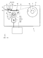
- FIG. 1 is a schematic diagram illustrating the entire printer of the embodiment.
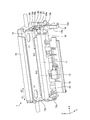
- FIG. 2 is a perspective view illustrating a printing unit of the printer according to the embodiment.
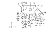
- FIG. 3 is a side view illustrating a printing unit according to the embodiment.
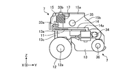
- FIG. 4 is a side view showing the printing section in the embodiment in a see-through manner.
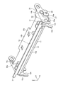
- FIG. 5 is a perspective view illustrating a first head support member and a second head support member of the printing unit according to the embodiment.
- FIG. 6 is a perspective view illustrating a second head support member and a frame member of the printing unit according to the embodiment.
- FIG. 7A is a perspective view for explaining an operation of removing the first head support member from the printing unit in the embodiment.
- FIG. 1 is a schematic diagram illustrating the entire printer of the embodiment.
- FIG. 2 is a perspective view illustrating a printing unit of the printer according to the embodiment.
- FIG. 3 is a side view illustrating a printing unit according to the embodiment.
- FIG. 4 is
- FIG. 7B is a perspective view for explaining an operation of removing the first head support member from the printing unit in the embodiment.
- FIG. 7C is a perspective view for explaining an operation of removing the first head support member from the printing unit in the embodiment.
- FIG. 7D is a perspective view for explaining an operation of removing the first head support member from the printing unit in the embodiment.
- FIG. 7E is a perspective view for explaining an operation of removing the first head support member from the printing unit in the embodiment.
- the printer according to the embodiment is a thermal printer that prints on a thermal paper such as a roll paper (continuous paper) or a label paper (seal paper) in which a label is superimposed on a release paper as a roll-shaped medium.
- a thermal paper such as a roll paper (continuous paper) or a label paper (seal paper) in which a label is superimposed on a release paper as a roll-shaped medium.
- the printer according to the present embodiment is described as printing on label paper as an example of a roll-shaped medium, but is not limited to a roll-shaped medium.
- FIG. 1 is a schematic diagram showing the entire printer of the embodiment.
- the printer 1 of the embodiment includes a supply unit 6 that supports a label sheet 3 as a roll-shaped medium, a printing unit 7 that prints on the label sheet 3 supplied from the supply unit 6, and a printing unit. And a take-up section 8 for taking up the label paper 3 that has passed through 7.
- the width direction of the printer 1 is shown as an X direction
- the depth direction of the printer 1 is shown as a Y direction
- the height direction of the printer 1 is shown as a Z direction. 1 and thereafter, the X, Y, and Z directions are shown similarly to FIG.
- the supply unit 6 has a rotating shaft 6a that supports the label paper 3.
- the printing unit 7 has a thermal head 11, a platen roller 12, and the like. Details of the printing unit 7 will be described later.
- the take-up section 8 includes a take-up shaft 21 to which one end of the label paper 3 is fixed and takes up the label paper 3, and a drive gear 22 that drives the take-up shaft 21 to rotate.
- the printer 1 has a transport path 41 through which the label paper 3 supplied from the supply section 6 is transported to the winding section 8 through the printing section 7, and transport rollers 42 along the transport path 41. Is arranged. Further, the printer 1 includes a drive unit 9 for driving the drive gear of the winding unit 8 and the platen roller 12 of the printing unit 7 to rotate.
- the driving unit 9 includes a transmission gear 51 for transmitting a driving force to the driving gear 22, a timing belt 52 for driving the transmission gear 51 and the platen roller 12, a driving motor 53 for driving the timing belt 52, and an electric power for the driving motor 53. And a power supply 54 for supplying the power. As shown in FIG. 1, the printer 1 supplies the label paper 3 by rotating the label paper 3 of the supply unit 6 counterclockwise, and rotates the winding shaft 21 of the winding unit 8 clockwise to rotate the label paper 3. Wind up the paper 3.
- FIG. 2 is a perspective view illustrating the printing unit 7 of the printer 1 according to the embodiment.
- FIG. 3 is a side view showing the printing unit 7 in the embodiment.
- FIG. 4 is a side view showing the printing unit 7 in the embodiment as seen through.
- the printing unit 7 includes a thermal head 11 for heating and printing the label paper 3, and a platen roller 12 for feeding the label paper 3 sandwiched between the thermal head 11.
- a first head support member 13 that supports the thermal head 11 a second head support member 14 that supports the first head support member 13, and a frame member 15 that supports the second head support member 14.
- the printing unit 7 includes a coil spring 17 as an urging member for urging the second head support member 14 in a direction for pressing the thermal head 11 against the peripheral surface of the platen roller 12, and a first spring 17 for the second head support member 14.
- a stopper member 18 for regulating the movement of the head support member 13 and a guide member 19 for guiding the label paper 3 passing between the thermal head 11 and the platen roller 12 are provided.
- the thermal head 11 is connected to a control unit (not shown) via wiring.
- the platen roller 12 is disposed so as to face the long thermal head 11, and is supported by a rotating shaft 12a.
- the rotating shaft 12a is supported by a structure (not shown) provided in the printer 1.
- the rotary shaft 12a is provided with a ring-shaped positioning member 26 for positioning the first head support member 13 with respect to the platen roller 12.
- the positioning member 26 has an engagement groove 26a with which a support piece 13b described later of the first head support member 13 is engaged.
- the engagement groove 26a is formed around the rotation shaft 12a.
- FIG. 5 is a perspective view showing the first head support member 13 and the second head support member 14 of the printing unit 7 in the embodiment.
- FIG. 6 is a perspective view illustrating the second head support member 14 and the frame member 15 of the printing unit 7 in the embodiment.
- the first head support member 13 includes a support plate 13a to which the thermal head 11 is fixed, a set of support pieces 13b and 13c supported by the second head support member 14, Having.
- Each of the support pieces 13b and 13c is provided with a first protrusion 27 and a second protrusion 28 supported by the support pieces 14b and 14c of the second head support member 14, respectively.
- the first protrusion 27 and the second protrusion 28 are formed as shafts that protrude in the axial direction (X direction) of the rotation shaft 12 a of the platen roller 12.
- the first head support member 13 is supported by the first protrusion 27 and the second protrusion 28 so as to be movable in the X direction with respect to the second head support member 14.
- an engagement recess 13d to be engaged with the engagement groove 26a of the positioning member 26 is formed on one support piece 13b of the first head support member 13.
- the other support piece 13c has an engagement recess 13e that engages with the rotation shaft 12a of the platen roller 12.
- the second head support member 14 includes a support plate 14 a disposed along the support plate 13 a of the first head support member 13, and a second support member 14 supported by the frame member 15. And a pair of support pieces 14b and 14c.
- Each of the support pieces 14b and 14c has a first support hole 29 that supports the first protrusion 27 of the first head support member 13 and a second support hole that supports the second protrusion 28 of the first head support member 13.
- a hole 30 is provided.
- the first head support member 13 is configured such that the first protrusion 27 is supported by the first support hole 29 and the second protrusion 28 is supported by the second support hole 30.
- 14 is provided movably in the axial direction (X direction) of a support shaft 36 that supports the stopper member 18, which will be described later.
- the first support hole 29 is formed as a round hole in each of the support pieces 14b and 14c of the second head support member 14, and the second support hole 30 is formed as a long hole extending in the Y direction.
- the second support hole 30 is formed as an elongated hole, and thus also functions as an adjustment hole for securing a clearance corresponding to manufacturing variations of the first head support member 13 and the second head support member 14.
- the first head support member 13 is attached to the second head support member 14 by adjusting the position of the first head support member 13 with respect to the second head support member 14 by the second support holes 30.
- the first support hole 29 of one of the support pieces 14b of the second head support member 14 has a first support hole 29 with respect to a Z direction which is a first direction orthogonal to an axial direction (X direction) of a support shaft 36 described later.
- a first groove 29 a that allows the one protrusion 27 to be inserted into and removed from the first support hole 29 is formed continuously with the first support hole 29.
- the second convex portion 28 is provided in the Y direction which is a second direction orthogonal to the axial direction (X direction) of the support shaft 36 and the first direction (Z direction). Is movably supported, and a second groove 30a that allows the second convex portion 28 to be inserted into and removed from the second support hole 30 in the first direction (Z direction) is continuous with the second support hole 30. It is formed.
- the size of the second head support member 14 in the axial direction (X direction) of the support shaft 36, that is, the direction in which the first protrusion 27 and the second protrusion 28 protrude, is larger than that of the first head support member 13. Are also large. Therefore, in a state where the first convex portion 27 is supported by the first support hole 29 and the second convex portion 28 is supported by the second support hole 30, the first head support member 13 is connected to the second head support member. 14 is provided so as to be movable in the X direction. Further, the second head support member 14 is formed with an engagement protrusion 31 that is engaged with the frame member 15 near each of the support pieces 14b and 14c. 4 and 5, the support plate 14a is provided with a fixed shaft 33a to which a set of coil springs 17 is attached.
- the frame member 15 includes a support plate 15a arranged along the support plate 14a of the second head support member 14, and a structure (not shown) provided in the printer 1. And a pair of supporting pieces 15b and 15c supported by
- a fixed shaft 33b to which a pair of coil springs 17 is attached is provided on the support plate 15a of the frame member 15, as shown in FIGS.
- the frame member 15 presses the second head support member 14 toward the platen roller 12 by the urging force of the coil spring 17 attached across the fixed shaft 33a of the first head support member 14 and the fixed shaft 33b of the support plate 15a. I do.
- the second head support member 14 is pressed by the coil spring 17 so that the platen roller 12 presses the thermal head 11 fixed to the first head support member 13.
- a fixing portion for fixing the wiring connected to the terminal of the thermal head 11 is formed on the support plate 15a.
- the support pieces 15b and 15c of the frame member 15 are formed with square hole-shaped engagement holes 32 with which the engagement protrusions 31 of the second head support member 14 are engaged.
- the posture of the second head support member 14 with respect to the frame member 15 is regulated by the engagement protrusion 31 being engaged with the engagement hole 32 of the second head support member 14.
- Each of the support pieces 15b and 15c is provided with a connection shaft 34 connected to the second head support member 14. Further, each support piece 15b, 15c is provided with a mounting shaft 35 that is mounted on the structure of the printer 1.
- the stopper member 18 has a restriction position P1 for restricting the movement of the first head support member 13 with respect to the second head support member 14, and a release position for releasing the restriction of the movement of the first head support member 13. It is provided movably with P2.
- the stopper member 18 is rotatably supported by a support shaft 36.
- the support shaft 36 is arranged in parallel along the rotation shaft 12a of the platen roller 12.
- the stopper member 18 is provided movably with respect to the second head support member 14 by rotating about the support shaft 36, and is provided detachably on the support piece 14 b of the second head support member 14. I have.
- the stopper member 18 is configured such that the engagement groove 18a engaged with the support piece 14b of the second head support member 14 and the support piece 13b of the first head support member 13 move in the axial direction (X2 direction) of the support shaft 36. And a regulating surface 18b for regulating the operation.
- the stopper member 18 is held by the second head support member 14 by being engaged with the support piece 14b of the second head support member 14 in the engagement groove 18a.
- the restricting surface 18b of the stopper member 18 restricts the movement of the first head support member 13 in the X2 direction by abutting against the support piece 13b of the first head support member 13.
- the support shaft 36 is provided with a plurality of transport rollers 42 at intervals in the axial direction of the support shaft 36.
- the guide member 19 is arranged along the transport direction of the label paper 3 passing between the thermal head 11 and the platen roller 12, and is supported by a support shaft 36.
- FIGS. 7A to 7E are perspective views for explaining an operation of removing the first head support member 13 from the printing unit 7 in the embodiment.
- the frame member 15 supporting the first head support member 13 and the second head support member 14 is rotated about the support shaft 36 with respect to the platen roller 12, so that the thermal head 11 is separated from the platen roller 12. Separated.
- the terminals of the wires connected to the control unit and the like are removed from the terminals of the thermal head 11.
- each support piece 13b, 13c of the first head support member 13 is inserted into the first support hole 29 with respect to each support piece 14b, 14c of the second head support member 14.
- the first head support member 13 is moved in the X2 direction with respect to the second head support member 14. Let it.
- the first protrusion 27 and the second protrusion 28 of the one support piece 13c are moved to the first protrusion 27c of the one support piece 14c of the second head support member 14. It is pulled out from the first support hole 29 and the second support hole 30.
- the first head support member 13 is configured such that the first convex portion 27 and the second convex portion 28 of the other support piece 13b are connected to the first support hole 29 of the other support piece 14b of the second head support member 14 and 2 It is in a state of being supported by the support holes 30.
- the first head support member 13 is moved around the second protrusion 28 of the support piece 13b with respect to the support piece 14b of the second head support member 14 (C in FIG. 7D).
- the first projection 27 of the support piece 13b is drawn out of the support piece 14b from the first support hole 29 of the support piece 14b through the first groove 29a.
- the first head support member 13 is connected to the support piece 14b of the second head support member 14, and the second convex portion 28 of the support piece 13b is inserted into
- the second convex portions 28 of the support pieces 13b pass through the second grooves 30a from the second support holes 30 of the support pieces 14b, It is pulled out of the support piece 14b.
- the first head support member 13 is detached from the second head support member 14 without using a tool, and is easily replaced with the first head support member 13 to which the new thermal head 11 is fixed. Can be. Further, according to the embodiment, when the first head support member 13 is detached from the second head support member 14, the urging force of the coil spring 17 for urging the second head support member 14 is directly applied to the first head support member 13. Since it does not act, the first head support member 13 can be moved relative to the second head support member 14 and easily removed without deforming the coil spring 17.
- the operation of attaching the first head support member 13 to which the new thermal head 11 is fixed to the printing unit 7 is opposite to the above-described removal operation.
- the first head support member 13 is attached to the second head support member 14.
- the first head support member 13 attached to the second head support member 14 is rotated about the support shaft 36 integrally with the frame member 15, thereby positioning the first head support member 13 provided on the rotation shaft 12 a of the platen roller 12.
- the engaging recess 13d of the support piece 13b is engaged with the engaging groove 26a of the member 26.
- the thermal head 11 fixed to the first head support member 13 is positioned at a predetermined position in the X, Y, and Z directions with respect to the platen roller 12.
- the thermal head 11 positioned in this manner is pressed by the platen roller 12 by being urged by the coil spring 17 via the second head support member 14 that supports the first head support member 13.
- the printing unit 7 of the printer 1 includes the first head support member 13 that supports the thermal head 11, the second head support member 14 that supports the first head support member 13, and the second head support member 14.
- the first head support member 13 supporting the thermal head 11 can be easily removed from the second head support member 14 without using a tool for removing the fixing screw, so that the thermal head 11 can be easily replaced. Can be done.
- the first head support member 13 does not deform the coil spring 17 for pressing the thermal head 11 against the platen roller 12. Can be easily attached and detached, so that the workability when replacing the thermal head 11 can be improved.
- the stopper member 18 of the printing unit 7 of the printer 1 of the embodiment is detachably provided on the second head support member 14. Thereby, the stopper member 18 can be easily held at the restriction position P1.
- the printing unit 7 of the printer 1 includes a rotation shaft 12 a that supports the platen roller 12, a positioning member 26 that is provided on the rotation shaft 12 a and that positions the first head support member 13 with respect to the platen roller 12. , Is provided. Accordingly, the first head support member 13 can be easily positioned by the positioning member 26, and the positional accuracy of the thermal head 11 with respect to the platen roller 12 can be improved.
- the printing unit 7 of the printer 1 includes a support shaft 36 provided along a rotation shaft 36a, and the stopper member 18 is supported rotatably around the support shaft 36. Accordingly, a structure in which the stopper member 18 easily and stably moves between the restriction position P1 and the release position P2 can be realized with a simple configuration. As a result, the reliability of the operation of restricting the movement of the first head support member 13 using the stopper member 18 can be improved, and the size of the printing section 7 and the size of the entire printer 1 can be reduced.
- the first convex portion 27 and the second convex portion 28 of the first head support member 13 correspond to the first support hole 29 and the second support hole of the second head support member 14.
- the first head support member 13 is provided so as to be movable in the axial direction (X direction) of the support shaft 36 with respect to the second head support member 14 while being supported by 30.
- the structure for regulating can be simplified. As a result, the size of the printing unit 7 and the size of the entire printer 1 can be reduced.
- the first support hole 29 of the second head support member 14 has the first protrusion in the first direction (Z direction) orthogonal to the axial direction of the support shaft 36.
- a first groove 29a that allows the portion 27 to be inserted into and removed from the first support hole 29 is formed.
- a second convex portion 28 is formed in the axial direction of the support shaft 36 and a second direction (Y direction) orthogonal to the first direction (Z direction).
- a second groove 30a is formed to be movably supported and to allow the second protrusion 28 to be inserted into and removed from the second support hole 30 in the first direction (Z direction).
- the first head support member 13 (the first convex portion 27 and the second convex portion 28) is moved.
- the clearance corresponding to the manufacturing variation of the second head support member 14 is ensured, so that the position of the first head support member 13 with respect to the second head support member 14 can be adjusted and attached.
- a structure in which the first head support member 13 can be adjusted with respect to the second head support member 14 and a structure in which the first head support member 13 can be attached to and detached from the second head support member 14, Both can be achieved with a simple configuration, and such a structure can be downsized.
Landscapes
- Electronic Switches (AREA)
- Common Mechanisms (AREA)
Abstract
プリンタは、媒体を加熱して印字するサーマルヘッドと、サーマルヘッドとの間に挟まれた媒体を送るプラテンローラと、サーマルヘッドを支持する第1ヘッド支持部材と、第1ヘッド支持部材を支持する第2ヘッド支持部材と、第2ヘッド支持部材を支持するフレーム部材と、サーマルヘッドをプラテンローラに押圧させる方向に第2ヘッド支持部材を付勢する付勢部材と、第2ヘッド支持部材に対する第1ヘッド支持部材の移動を規制する規制位置と、規制を解除する解除位置とに移動可能に設けられたストッパ部材と、を備える。
Description
本発明は、プリンタに関する。
プリンタとしては、媒体である感熱紙に印字するサーマルヘッドと、サーマルヘッドとの間に挟まれた感熱紙を送るプラテンローラと、を備えるサーマルプリンタが知られている。
上述したプリンタには、サーマルヘッドがヘッド支持体にネジ止めされた構成がある。この構成の場合には、サーマルヘッドを交換する際に、工具を用いて固定ネジを着脱することになり、サーマルヘッドの交換作業が煩雑である。
開示の技術は、上記に鑑みてなされたものであって、サーマルヘッドの交換を容易に行うことができるプリンタを提供することを目的とする。
本願の開示するプリンタの一態様は、媒体を加熱して印字するサーマルヘッドと、前記サーマルヘッドとの間に挟まれた媒体を送るプラテンローラと、前記サーマルヘッドを支持する第1ヘッド支持部材と、前記第1ヘッド支持部材を支持する第2ヘッド支持部材と、前記第2ヘッド支持部材を支持するフレーム部材と、前記サーマルヘッドを前記プラテンローラに押圧させる方向に前記第2ヘッド支持部材を付勢する付勢部材と、前記第2ヘッド支持部材に対する前記第1ヘッド支持部材の移動を規制する規制位置と、前記規制を解除する解除位置とに移動可能に設けられたストッパ部材と、を備える。
本願の開示するプリンタの一態様によれば、サーマルヘッドの交換を容易に行うことができる。
以下に、本願の開示するプリンタの実施例を図面に基づいて詳細に説明する。なお、以下の実施例によって、本願の開示するプリンタが限定されるものではない。
(プリンタの構成)
実施例のプリンタは、ロール状媒体として、ロール紙(連続紙)や、ラベルが剥離紙に重ねられたラベル紙(シール紙)等の感熱紙に印字を行うサーマルプリンタである。本実施例のプリンタは、ロール状媒体の一例としてラベル紙に印字を行うものとして説明するが、ロール状媒体に限定されるものではない。
実施例のプリンタは、ロール状媒体として、ロール紙(連続紙)や、ラベルが剥離紙に重ねられたラベル紙(シール紙)等の感熱紙に印字を行うサーマルプリンタである。本実施例のプリンタは、ロール状媒体の一例としてラベル紙に印字を行うものとして説明するが、ロール状媒体に限定されるものではない。
図1は、実施例のプリンタ全体を示す模式図である。図1に示すように、実施例のプリンタ1は、ロール状媒体としてのラベル紙3を支持する供給部6と、供給部6から供給されたラベル紙3に印字する印字部7と、印字部7を通過したラベル紙3を巻き取る巻取部8と、を備える。図1において、プリンタ1の幅方向をX方向とし、プリンタ1の奥行き方向をY方向とし、プリンタの高さ方向をZ方向として示す。図1以降においても、X、Y、Z方向について図1と同様に示す。
供給部6は、ラベル紙3を支持する回転軸6aを有する。印字部7は、サーマルヘッド11、プラテンローラ12等を有する。印字部7の詳細については後述する。巻取部8は、ラベル紙3の一端が固定されてラベル紙3を巻き取る巻取軸21と、巻取軸21を回転駆動させる駆動ギア22と、を有する。
また、プリンタ1は、供給部6から供給されたラベル紙3が、印字部7を通って巻取部8へ搬送される搬送路41を有しており、搬送路41に沿って搬送ローラ42が配置されている。さらに、プリンタ1は、巻取部8の駆動ギア及び印字部7のプラテンローラ12を回転駆動する駆動部9を備える。駆動部9は、駆動ギア22に駆動力を伝達する伝達ギア51と、伝達ギア51及びプラテンローラ12を駆動するタイミングベルト52と、タイミングベルト52を駆動する駆動モータ53と、駆動モータ53に電力を供給する電源54と、を有する。プリンタ1は、図1に示すように、供給部6のラベル紙3が反時計方向へ回転してラベル紙3を供給し、巻取部8の巻取軸21が時計方向に回転してラベル紙3を巻き取る。
(印字部の構成)
図2は、実施例のプリンタ1の印字部7を示す斜視図である。図3は、実施例における印字部7を示す側面図である。図4は、実施例における印字部7を透視して示す側面図である。
図2は、実施例のプリンタ1の印字部7を示す斜視図である。図3は、実施例における印字部7を示す側面図である。図4は、実施例における印字部7を透視して示す側面図である。
図2、図3及び図4に示すように、印字部7は、ラベル紙3を加熱して印字するサーマルヘッド11と、サーマルヘッド11との間に挟まれたラベル紙3を送るプラテンローラ12と、サーマルヘッド11を支持する第1ヘッド支持部材13と、第1ヘッド支持部材13を支持する第2ヘッド支持部材14と、第2ヘッド支持部材14を支持するフレーム部材15と、を備える。
また、印字部7は、サーマルヘッド11をプラテンローラ12の周面に押圧させる方向に第2ヘッド支持部材14を付勢する付勢部材としてのコイルバネ17と、第2ヘッド支持部材14に対する第1ヘッド支持部材13の移動を規制するストッパ部材18と、サーマルヘッド11とプラテンローラ12との間を通過するラベル紙3を案内するガイド部材19と、を備える。
サーマルヘッド11は、図示しない制御部等に配線を介して接続されている。プラテンローラ12は、長尺状のサーマルヘッド11と対向して配置されており、回転軸12aに支持されている。回転軸12aは、プリンタ1が備える構造体(図示せず)に支持されている。また、回転軸12aには、第1ヘッド支持部材13を、プラテンローラ12に対して位置決めするためのリング状の位置決め部材26が設けられている。位置決め部材26は、第1ヘッド支持部材13の後述する支持片13bが係合される係合溝26aを有する。係合溝26aは、回転軸12aまわりに沿って形成されている。位置決め部材26によって第1ヘッド支持部材13が位置決めされることで、サーマルヘッド11が図中のX、Y、Z方向に対する所定の位置に位置決めされる。
図5は、実施例における印字部7の第1ヘッド支持部材13及び第2ヘッド支持部材14を示す斜視図である。図6は、実施例における印字部7の第2ヘッド支持部材14及びフレーム部材15を示す斜視図である。
図2及び図5に示すように、第1ヘッド支持部材13は、サーマルヘッド11が固定される支持板13aと、第2ヘッド支持部材14に支持される一組の支持片13b、13cと、を有する。支持片13b、13cの各々には、第2ヘッド支持部材14の支持片14b、14cにそれぞれ支持される第1凸部27及び第2凸部28が設けられている。第1凸部27及び第2凸部28は、プラテンローラ12の回転軸12aの軸方向(X方向)に突出する軸部として形成されている。第1ヘッド支持部材13は、第1凸部27及び第2凸部28によって、第2ヘッド支持部材14に対してX方向に移動可能に支持されている。また、第1ヘッド支持部材13の一方の支持片13bには、位置決め部材26の係合溝26aに係合される係合凹部13dが形成されている。他方の支持片13cには、プラテンローラ12の回転軸12aに係合する係合凹部13eが形成されている。
図2、図5及び図6に示すように、第2ヘッド支持部材14は、第1ヘッド支持部材13の支持板13aに沿って配置される支持板14aと、フレーム部材15に支持される一組の支持片14b、14cと、を有する。支持片14b、14cの各々には、第1ヘッド支持部材13の第1凸部27を支持する第1支持穴29と、第1ヘッド支持部材13の第2凸部28を支持する第2支持穴30と、が設けられている。そして、第1ヘッド支持部材13は、第1凸部27が第1支持穴29に支持され、かつ、第2凸部28が第2支持穴30に支持された状態で、第2ヘッド支持部材14に対して、ストッパ部材18を支持する後述の支持軸36の軸方向(X方向)に移動可能に設けられている。
また、第2ヘッド支持部材14の各支持片14b、14cには、第1支持穴29が丸穴として形成されており、第2支持穴30がY方向に延びる長穴として形成されている。第2支持穴30は、長穴に形成されることにより、第1ヘッド支持部材13及び第2ヘッド支持部材14の製造上のバラツキに対応するクリアランスを確保するための調整穴としても機能する。第2支持穴30により、第1ヘッド支持部材13は、第2ヘッド支持部材14に対する第1ヘッド支持部材13の位置が調整されて取り付けられる。
また、第2ヘッド支持部材14の一方の支持片14bの第1支持穴29には、後述する支持軸36の軸方向(X方向)に直交する第1方向であるZ方向に対して、第1凸部27を第1支持穴29内から挿脱可能にする第1溝29aが、第1支持穴29に連続して形成されている。支持片14bの第2支持穴30には、支持軸36の軸方向(X方向)及び第1方向(Z方向)とそれぞれ直交する第2方向であるY方向に対して、第2凸部28が移動可能に支持されると共に、第1方向(Z方向)に対して、第2凸部28を第2支持穴30から挿脱可能にする第2溝30aが、第2支持穴30に連続して形成されている。
また、第2ヘッド支持部材14は、支持軸36の軸方向(X方向)、すなわち、第1凸部27及び第2凸部28が突出する方向に対する大きさが、第1ヘッド支持部材13よりも大きく形成されている。このため、第1凸部27が第1支持穴29に支持され、かつ、第2凸部28が第2支持穴30に支持された状態で、第1ヘッド支持部材13が第2ヘッド支持部材14に対してX方向に移動可能に設けられている。また、第2ヘッド支持部材14には、各支持片14b、14cの近傍に、フレーム部材15に係合される係合突起31が形成されている。また、支持板14aには、図4及び図5に示すように、一組のコイルバネ17が取り付けられる固定軸33aが設けられている。
図2、図4及び図6に示すように、フレーム部材15は、第2ヘッド支持部材14の支持板14aに沿って配置される支持板15aと、プリンタ1が備える構造体(図示せず)に支持される一組の支持片15b、15cと、を有する。
フレーム部材15の支持板15aには、図4及び図6に示すように、一組のコイルバネ17が取り付けられる固定軸33bが設けられている。フレーム部材15は、第1ヘッド支持部材14の固定軸33aと支持板15aの固定軸33bとに跨って取り付けられたコイルバネ17の付勢力によって、第2ヘッド支持部材14をプラテンローラ12側へ押圧する。第2ヘッド支持部材14は、コイルバネ17によって押圧されることにより、第1ヘッド支持部材13に固定されたサーマルヘッド11を、プラテンローラ12に押圧させる。また、支持板15aには、図示しないが、サーマルヘッド11の端子に接続される配線を固定する固定部が形成されている。
フレーム部材15の支持片15b、15cには、第2ヘッド支持部材14の係合突起31が係合される角穴状の係合穴32が形成されている。第2ヘッド支持部材14は、係合突起31が係合穴32に係合されることで、フレーム部材15に対する第2ヘッド支持部材14の姿勢が規制されている。また、各支持片15b、15cには、第2ヘッド支持部材14と連結される連結軸34が設けられている。さらに、各支持片15b、15cには、プリンタ1の構造体に取り付けられる取付軸35が設けられている。
ストッパ部材18は、図2に示すように、第2ヘッド支持部材14に対する第1ヘッド支持部材13の移動を規制する規制位置P1と、第1ヘッド支持部材13の移動の規制を解除する解除位置P2とに移動可能に設けられている。ストッパ部材18は、支持軸36に回動可能に支持されている。支持軸36は、プラテンローラ12の回転軸12aに沿って平行に配置されている。ストッパ部材18は、支持軸36まわりに回動することで、第2ヘッド支持部材14に対して移動可能に設けられており、第2ヘッド支持部材14の支持片14bに着脱可能に設けられている。
ストッパ部材18は、第2ヘッド支持部材14の支持片14bに係合される係合溝18aと、第1ヘッド支持部材13の支持片13bが、支持軸36の軸方向(X2方向)に移動することを規制する規制面18bと、を有する。
ストッパ部材18は、係合溝18aに第2ヘッド支持部材14の支持片14bに係合されることで、第2ヘッド支持部材14に保持される。第1ヘッド支持部材13が第2ヘッド支持部材14に対してX1方向に移動されて、第2ヘッド支持部材14の支持片14cに第1ヘッド支持部材13の支持片13cが当接された状態で、ストッパ部材18の規制面18bは、第1ヘッド支持部材13の支持片13bに突き当てられることによって、第1ヘッド支持部材13がX2方向に移動することを規制する。このため、ストッパ部材18を規制位置P1から解除位置P2へ移動させることで、第2ヘッド支持部材14に対する第1ヘッド支持部材13の移動の規制を解除することが可能になり、第2ヘッド支持部材14に取り付けられた第1ヘッド支持部材13を、第2ヘッド支持部材14から容易に取り外すことができる。
また、支持軸36には、支持軸36の軸方向に間隔をあけて複数の搬送ローラ42が設けられている。ガイド部材19は、サーマルヘッド11とプラテンローラ12との間を通過するラベル紙3の搬送方向に沿って配置されており、支持軸36に支持されている。
(サーマルヘッドの交換時の動作)
以上のように構成された印字部7について、サーマルヘッド11の交換時に、印字部7から第1ヘッド支持部材13を取り外す動作を説明する。図7A~7Eは、実施例における印字部7から第1ヘッド支持部材13を取り外す動作を説明するための斜視図である。まず、第1ヘッド支持部材13及び第2ヘッド支持部材14を支持したフレーム部材15が、プラテンローラ12に対して、支持軸36まわりに回動されることで、サーマルヘッド11がプラテンローラ12から分離される。また、第1ヘッド支持部材13を印字部7から取り外す際、サーマルヘッド11の端子から、制御部等に接続された配線の端子が取り外される。
以上のように構成された印字部7について、サーマルヘッド11の交換時に、印字部7から第1ヘッド支持部材13を取り外す動作を説明する。図7A~7Eは、実施例における印字部7から第1ヘッド支持部材13を取り外す動作を説明するための斜視図である。まず、第1ヘッド支持部材13及び第2ヘッド支持部材14を支持したフレーム部材15が、プラテンローラ12に対して、支持軸36まわりに回動されることで、サーマルヘッド11がプラテンローラ12から分離される。また、第1ヘッド支持部材13を印字部7から取り外す際、サーマルヘッド11の端子から、制御部等に接続された配線の端子が取り外される。
図7Aに示すように、サーマルヘッド11が固定された第1ヘッド支持部材13は、支持片13bにストッパ部材18の規制面18bが突き当てられていることで、X2方向への移動が規制されている。このため、図7A及び図7Bに示すように、第2ヘッド支持部材14に保持されたストッパ部材18を支持軸36まわりに回動することで、ストッパ部材18を規制位置P1から解除位置P2へ移動させる。ストッパ部材18は、解除位置P2へ移動されることで、第1ヘッド支持部材13の支持片13bから規制面18bが離されて、第1ヘッド支持部材13がX2方向へ移動可能となる。
続いて、図7B及び図7Cに示すように、第1ヘッド支持部材13の各支持片13b、13cを、第2ヘッド支持部材14の各支持片14b、14cに対して、第1支持穴29及び第2支持穴30に支持された第1凸部27及び第2凸部28をX2方向に移動させることで、第1ヘッド支持部材13を第2ヘッド支持部材14に対してX2方向に移動させる。第1ヘッド支持部材13は、X方向に移動されることで、一方の支持片13cの第1凸部27及び第2凸部28が、第2ヘッド支持部材14の一方の支持片14cの第1支持穴29及び第2支持穴30から引き出される。これにより、第1ヘッド支持部材13は、他方の支持片13bの第1凸部27及び第2凸部28が、第2ヘッド支持部材14の他方の支持片14bの第1支持穴29及び第2支持穴30に支持されている状態になる。
続いて、図7C及び図7Dに示すように、第1ヘッド支持部材13を、第2ヘッド支持部材14の支持片14bに対して、支持片13bの第2凸部28まわり(図7DのC方向)に回動させることで、支持片13bの第1凸部27が、支持片14bの第1支持穴29から第1溝29aを通って、支持片14bの外方へ引き出される。引き続き、図7D及び図7Eに示すように、第1ヘッド支持部材13を、第2ヘッド支持部材14の支持片14bに対して、支持片13bの第2凸部28を、長穴状の第2支持穴30に沿ってY方向に移動させると共にZ方向に移動させることで、支持片13bの第2凸部28が、支持片14bの第2支持穴30から第2溝30aを通って、支持片14bの外方へ引き出される。
このように第1ヘッド支持部材13は、工具を用いることなく、第2ヘッド支持部材14から取り外されて、新たなサーマルヘッド11が固定された第1ヘッド支持部材13と容易に交換を行うことができる。また、実施例によれば、第1ヘッド支持部材13を第2ヘッド支持部材14から取り外す際に、第2ヘッド支持部材14を付勢するコイルバネ17の付勢力が第1ヘッド支持部材13に直接作用していないので、コイルバネ17を変形させることなく、第1ヘッド支持部材13を第2ヘッド支持部材14に対して移動させて容易に取り外すことができる。
上述のように印字部7から第1ヘッド支持部材13を取り外した後、新たなサーマルヘッド11が固定された第1ヘッド支持部材13を印字部7に取り付ける動作は、上述した取り外し動作と逆に行うことで、第1ヘッド支持部材13が第2ヘッド支持部材14に取り付けられる。第2ヘッド支持部材14に取り付けられた第1ヘッド支持部材13は、フレーム部材15と一体的に支持軸36まわりに回動されることで、プラテンローラ12の回転軸12aに設けられたた位置決め部材26の係合溝26aに、支持片13bの係合凹部13dが係合される。これにより、第1ヘッド支持部材13に固定されたサーマルヘッド11は、プラテンローラ12に対してX、Y、Z方向に対する所定の位置に位置決めされる。また、このように位置決めされたサーマルヘッド11は、第1ヘッド支持部材13を支持する第2ヘッド支持部材14を介して、コイルバネ17によって付勢されることで、プラテンローラ12に押圧される。
上述したように実施例のプリンタ1の印字部7は、サーマルヘッド11を支持する第1ヘッド支持部材13と、第1ヘッド支持部材13を支持する第2ヘッド支持部材14と、第2ヘッド支持部材14を支持するフレーム部材15と、サーマルヘッド11をプラテンローラ12に押圧させる方向に第2ヘッド支持部材14を付勢するコイルバネ17と、第2ヘッド支持部材14に対する第1ヘッド支持部材13の移動を規制する規制位置P1と、規制を解除する解除位置P2とに移動可能に設けられたストッパ部材18と、を備える。これにより、ストッパ部材18を規制位置P1から解除位置P2へ移動することで、第2ヘッド支持部材14に対する第1ヘッド支持部材13の移動の規制を解除することができる。したがって、サーマルヘッド11を支持する第1ヘッド支持部材13を、固定ネジを取り外す工具を用いることなく、第2ヘッド支持部材14から容易に取り外すことが可能になるので、サーマルヘッド11の交換を容易に行うことができる。加えて、第1ヘッド支持部材13を第2ヘッド支持部材14に対して着脱する際に、サーマルヘッド11をプラテンローラ12に押圧させるためのコイルバネ17を変形させることなく、第1ヘッド支持部材13を容易に着脱することが可能になるので、サーマルヘッド11の交換時の作業性を高めることができる。
また、実施例のプリンタ1の印字部7のストッパ部材18は、第2ヘッド支持部材14に着脱可能に設けられている。これにより、ストッパ部材18を規制位置P1に容易に保持することができる。
また、実施例のプリンタ1の印字部7は、プラテンローラ12を支持する回転軸12aと、回転軸12aに設けられてプラテンローラ12に対して第1ヘッド支持部材13を位置決めする位置決め部材26と、を備える。これにより、第1ヘッド支持部材13を位置決め部材26によって容易に位置決めすることが可能になり、プラテンローラ12に対するサーマルヘッド11の位置精度を高めることが可能になる。
また、実施例のプリンタ1の印字部7は、回転軸36aに沿って設けられた支持軸36を備えており、ストッパ部材18が、支持軸36まわりに回動可能に支持されている、これにより、ストッパ部材18が規制位置P1と解除位置P2とに容易かつ安定的に移動する構造を簡素な構成で実現することができる。その結果、ストッパ部材18を用いた第1ヘッド支持部材13の移動の規制動作の信頼性を高めると共に、印字部7の小型化、プリンタ1全体の小型化を図ることができる。
また、実施例のプリンタ1の印字部7において、第1ヘッド支持部材13の第1凸部27及び第2凸部28が、第2ヘッド支持部材14の第1支持穴29及び第2支持穴30に支持された状態で、第1ヘッド支持部材13は、第2ヘッド支持部材14に対して支持軸36の軸方向(X方向)に移動可能に設けられている。これにより、第1ヘッド支持部材13が第2ヘッド支持部材14に対して移動可能に支持される構造と、ストッパ部材18を用いて第2ヘッド支持部材14に対する第1ヘッド支持部材13の移動を規制する構造とを簡素化することができる。その結果、印字部7の小型化、プリンタ1全体の小型化を図ることができる。
また、実施例のプリンタ1の印字部7において、第2ヘッド支持部材14の第1支持穴29には、支持軸36の軸方向に直交する第1方向(Z方向)に対して第1凸部27を第1支持穴29から挿脱可能にする第1溝29aが形成されている。また、第2ヘッド支持部材14の第2支持穴30には、支持軸36の軸方向及び第1方向(Z方向)と直交する第2方向(Y方向)に対して第2凸部28が移動可能に支持されると共に、第1方向(Z方向)に対して第2凸部28を第2支持穴30から挿脱可能にする第2溝30aが形成されている。このように第2支持穴30に対して第2凸部28が第2方向(Y方向)に移動可能とすることで、第1ヘッド支持部材13(第1凸部27及び第2凸部28)及び第2ヘッド支持部材14の製造上のバラツキに対応するクリアランスが確保されるので、第2ヘッド支持部材14に対して第1ヘッド支持部材13の位置を調整して取り付けることができる。このため、第2ヘッド支持部材14に対して第1ヘッド支持部材13を調整可能とする構造と、第2ヘッド支持部材14に対して第1ヘッド支持部材13を着脱可能にする構造とを、簡素な構成で両立すると共に、このような構造を小型化することができる。
1 プリンタ
3 ラベル紙(媒体)
7 印字部
11 サーマルヘッド
12 プラテンローラ
12a 回転軸
13 第1ヘッド支持部材
14 第2ヘッド支持部材
15 フレーム部材
17 コイルバネ(付勢部材)
18 ストッパ部材
18b 規制面
26 位置決め部材
27 第1凸部
28 第2凸部
29 第1支持穴
29a 第1溝
30 第2支持穴
30a 第2溝
36 支持軸
P1 規制位置
P2 解除位置
3 ラベル紙(媒体)
7 印字部
11 サーマルヘッド
12 プラテンローラ
12a 回転軸
13 第1ヘッド支持部材
14 第2ヘッド支持部材
15 フレーム部材
17 コイルバネ(付勢部材)
18 ストッパ部材
18b 規制面
26 位置決め部材
27 第1凸部
28 第2凸部
29 第1支持穴
29a 第1溝
30 第2支持穴
30a 第2溝
36 支持軸
P1 規制位置
P2 解除位置
Claims (6)
- 媒体を加熱して印字するサーマルヘッドと、
前記サーマルヘッドとの間に挟まれた媒体を送るプラテンローラと、
前記サーマルヘッドを支持する第1ヘッド支持部材と、
前記第1ヘッド支持部材を支持する第2ヘッド支持部材と、
前記第2ヘッド支持部材を支持するフレーム部材と、
前記サーマルヘッドを前記プラテンローラに押圧させる方向に前記第2ヘッド支持部材を付勢する付勢部材と、
前記第2ヘッド支持部材に対する前記第1ヘッド支持部材の移動を規制する規制位置と、前記規制を解除する解除位置とに移動可能に設けられたストッパ部材と、を備えるプリンタ。 - 前記ストッパ部材は、前記第2ヘッド支持部材に着脱可能に設けられている、
請求項1に記載のプリンタ。 - 前記プラテンローラを支持する回転軸と、
前記回転軸に設けられ、前記プラテンローラに対して前記第1ヘッド支持部材を位置決めする位置決め部材と、
を更に備える、請求項1に記載のプリンタ。 - 前記回転軸に沿って設けられた支持軸を更に備え、
前記ストッパ部材は、前記支持軸まわりに回動可能に支持されている、
請求項3に記載のプリンタ。 - 前記第1ヘッド支持部材は、前記第2ヘッド支持部材に支持される凸部を有し、
前記第2ヘッド支持部材は、前記凸部を支持する支持穴を有し、
前記第1ヘッド支持部材は、前記凸部が前記支持穴に支持された状態で、前記第2ヘッド支持部材に対して前記支持軸の軸方向に移動可能に設けられている、
請求項4に記載のプリンタ。 - 前記凸部は、前記支持軸の軸方向に突出する第1凸部及び第2凸部を含み、
前記支持穴は、前記第1凸部を支持する第1支持穴と、前記第2凸部を支持する第2支持穴と、を含み、
前記第1支持穴には、前記支持軸の軸方向に交差する第1方向に対して前記第1凸部を前記第1支持穴から挿脱可能にする第1溝が、前記第1支持穴に連続して形成され、
前記第2支持穴には、前記支持軸の軸方向及び前記第1方向と交差する第2方向に対して前記第2凸部が移動可能に支持されると共に、前記第1方向に対して前記第2凸部を前記第2支持穴から挿脱可能にする第2溝が、前記第2支持穴に連続して形成されている、
請求項5に記載のプリンタ。
Priority Applications (2)
| Application Number | Priority Date | Filing Date | Title |
|---|---|---|---|
| PCT/JP2018/032354 WO2020044534A1 (ja) | 2018-08-31 | 2018-08-31 | プリンタ |
| JP2020539982A JP6941239B2 (ja) | 2018-08-31 | 2018-08-31 | プリンタ |
Applications Claiming Priority (1)
| Application Number | Priority Date | Filing Date | Title |
|---|---|---|---|
| PCT/JP2018/032354 WO2020044534A1 (ja) | 2018-08-31 | 2018-08-31 | プリンタ |
Publications (1)
| Publication Number | Publication Date |
|---|---|
| WO2020044534A1 true WO2020044534A1 (ja) | 2020-03-05 |
Family
ID=69644022
Family Applications (1)
| Application Number | Title | Priority Date | Filing Date |
|---|---|---|---|
| PCT/JP2018/032354 Ceased WO2020044534A1 (ja) | 2018-08-31 | 2018-08-31 | プリンタ |
Country Status (2)
| Country | Link |
|---|---|
| JP (1) | JP6941239B2 (ja) |
| WO (1) | WO2020044534A1 (ja) |
Citations (3)
| Publication number | Priority date | Publication date | Assignee | Title |
|---|---|---|---|---|
| JPH03268983A (ja) * | 1990-03-19 | 1991-11-29 | Nippon Denshi Kagaku Kk | サーマル印字装置 |
| JP2004262016A (ja) * | 2003-02-28 | 2004-09-24 | Sato Corp | サーマルプリンターにおけるサーマルヘッド着脱装置 |
| US20050276645A1 (en) * | 2004-03-03 | 2005-12-15 | Zih Corp. | Printer with quick release print head and platen to promote installation and removal of same |
-
2018
- 2018-08-31 JP JP2020539982A patent/JP6941239B2/ja active Active
- 2018-08-31 WO PCT/JP2018/032354 patent/WO2020044534A1/ja not_active Ceased
Patent Citations (3)
| Publication number | Priority date | Publication date | Assignee | Title |
|---|---|---|---|---|
| JPH03268983A (ja) * | 1990-03-19 | 1991-11-29 | Nippon Denshi Kagaku Kk | サーマル印字装置 |
| JP2004262016A (ja) * | 2003-02-28 | 2004-09-24 | Sato Corp | サーマルプリンターにおけるサーマルヘッド着脱装置 |
| US20050276645A1 (en) * | 2004-03-03 | 2005-12-15 | Zih Corp. | Printer with quick release print head and platen to promote installation and removal of same |
Also Published As
| Publication number | Publication date |
|---|---|
| JP6941239B2 (ja) | 2021-09-29 |
| JPWO2020044534A1 (ja) | 2021-03-11 |
Similar Documents
| Publication | Publication Date | Title |
|---|---|---|
| JP4294074B1 (ja) | サーマルプリンタ | |
| JP2011073372A (ja) | サーマルプリンタ | |
| US20080193184A1 (en) | Printer | |
| WO2020044534A1 (ja) | プリンタ | |
| JP4633140B2 (ja) | プリンタ | |
| US11897273B2 (en) | Print device | |
| JP5698473B2 (ja) | 印字ユニット及び印字装置 | |
| JP7131246B2 (ja) | 印刷装置、及びモーター | |
| JP6029849B2 (ja) | プリンタ | |
| JP4914619B2 (ja) | ヘッド支持構造体、印字装置、熱活性化装置、およびプリンタ | |
| JP4563309B2 (ja) | 給紙カセット | |
| JP4111819B2 (ja) | プリンタ | |
| US20150266682A1 (en) | Image forming apparatus | |
| JP4595089B2 (ja) | 印画位置決め機構及びプリンタ | |
| JP7749951B2 (ja) | 印刷装置 | |
| JP6451988B2 (ja) | スタンプ装置、および、スタンプ装置を備える印刷機 | |
| JP2014008620A (ja) | プリンタ | |
| JP5704999B2 (ja) | サーマルプリンタ装置 | |
| JP5197272B2 (ja) | プラテンローラの位置決め機構及びこれを備えたプリンタ | |
| JP4628859B2 (ja) | サーマルヘッド位置決め機構及びサーマルプリンタ | |
| WO2020063235A1 (zh) | 准确定位热印头的结构及打印单元及打印设备 | |
| JP2006036515A (ja) | ロール紙支持装置 | |
| JP2011251346A (ja) | カッタ及びプリンタ | |
| US8436879B2 (en) | Thermal head mechanism, printing device using the same, and method of supporting thermal head | |
| JP4357333B2 (ja) | サーマルヘッド |
Legal Events
| Date | Code | Title | Description |
|---|---|---|---|
| 121 | Ep: the epo has been informed by wipo that ep was designated in this application |
Ref document number: 18931615 Country of ref document: EP Kind code of ref document: A1 |
|
| ENP | Entry into the national phase |
Ref document number: 2020539982 Country of ref document: JP Kind code of ref document: A |
|
| NENP | Non-entry into the national phase |
Ref country code: DE |
|
| 122 | Ep: pct application non-entry in european phase |
Ref document number: 18931615 Country of ref document: EP Kind code of ref document: A1 |