WO2020044526A1 - 空調機 - Google Patents
空調機 Download PDFInfo
- Publication number
- WO2020044526A1 WO2020044526A1 PCT/JP2018/032294 JP2018032294W WO2020044526A1 WO 2020044526 A1 WO2020044526 A1 WO 2020044526A1 JP 2018032294 W JP2018032294 W JP 2018032294W WO 2020044526 A1 WO2020044526 A1 WO 2020044526A1
- Authority
- WO
- WIPO (PCT)
- Prior art keywords
- motors
- motor
- inverter
- rotation speed
- voltage
- Prior art date
- Legal status (The legal status is an assumption and is not a legal conclusion. Google has not performed a legal analysis and makes no representation as to the accuracy of the status listed.)
- Ceased
Links
Images





Classifications
-
- H—ELECTRICITY
- H02—GENERATION; CONVERSION OR DISTRIBUTION OF ELECTRIC POWER
- H02P—CONTROL OR REGULATION OF ELECTRIC MOTORS, ELECTRIC GENERATORS OR DYNAMO-ELECTRIC CONVERTERS; CONTROLLING TRANSFORMERS, REACTORS OR CHOKE COILS
- H02P5/00—Arrangements specially adapted for regulating or controlling the speed or torque of two or more electric motors
- H02P5/74—Arrangements specially adapted for regulating or controlling the speed or torque of two or more electric motors controlling two or more AC dynamo-electric motors
-
- H—ELECTRICITY
- H02—GENERATION; CONVERSION OR DISTRIBUTION OF ELECTRIC POWER
- H02P—CONTROL OR REGULATION OF ELECTRIC MOTORS, ELECTRIC GENERATORS OR DYNAMO-ELECTRIC CONVERTERS; CONTROLLING TRANSFORMERS, REACTORS OR CHOKE COILS
- H02P6/00—Arrangements for controlling synchronous motors or other dynamo-electric motors using electronic commutation dependent on the rotor position; Electronic commutators therefor
- H02P6/14—Electronic commutators
- H02P6/16—Circuit arrangements for detecting position
- H02P6/18—Circuit arrangements for detecting position without separate position detecting elements
- H02P6/182—Circuit arrangements for detecting position without separate position detecting elements using back-emf in windings
-
- F—MECHANICAL ENGINEERING; LIGHTING; HEATING; WEAPONS; BLASTING
- F24—HEATING; RANGES; VENTILATING
- F24F—AIR-CONDITIONING; AIR-HUMIDIFICATION; VENTILATION; USE OF AIR CURRENTS FOR SCREENING
- F24F11/00—Control or safety arrangements
- F24F11/88—Electrical aspects, e.g. circuits
-
- H—ELECTRICITY
- H02—GENERATION; CONVERSION OR DISTRIBUTION OF ELECTRIC POWER
- H02P—CONTROL OR REGULATION OF ELECTRIC MOTORS, ELECTRIC GENERATORS OR DYNAMO-ELECTRIC CONVERTERS; CONTROLLING TRANSFORMERS, REACTORS OR CHOKE COILS
- H02P5/00—Arrangements specially adapted for regulating or controlling the speed or torque of two or more electric motors
- H02P5/46—Arrangements specially adapted for regulating or controlling the speed or torque of two or more electric motors for speed regulation of two or more dynamo-electric motors in relation to one another
-
- F—MECHANICAL ENGINEERING; LIGHTING; HEATING; WEAPONS; BLASTING
- F24—HEATING; RANGES; VENTILATING
- F24F—AIR-CONDITIONING; AIR-HUMIDIFICATION; VENTILATION; USE OF AIR CURRENTS FOR SCREENING
- F24F2110/00—Control inputs relating to air properties
- F24F2110/10—Temperature
-
- F—MECHANICAL ENGINEERING; LIGHTING; HEATING; WEAPONS; BLASTING
- F24—HEATING; RANGES; VENTILATING
- F24F—AIR-CONDITIONING; AIR-HUMIDIFICATION; VENTILATION; USE OF AIR CURRENTS FOR SCREENING
- F24F2110/00—Control inputs relating to air properties
- F24F2110/10—Temperature
- F24F2110/12—Temperature of the outside air
-
- F—MECHANICAL ENGINEERING; LIGHTING; HEATING; WEAPONS; BLASTING
- F24—HEATING; RANGES; VENTILATING
- F24F—AIR-CONDITIONING; AIR-HUMIDIFICATION; VENTILATION; USE OF AIR CURRENTS FOR SCREENING
- F24F2120/00—Control inputs relating to users or occupants
- F24F2120/10—Occupancy
- F24F2120/14—Activity of occupants
Definitions
- the present invention relates to an air conditioner.
- ⁇ In order to operate a permanent magnet synchronous motor (PMS motor), it is necessary to control current and voltage in accordance with the position of the magnetic pole of the rotor of the PMS motor. To detect the magnetic pole position, a position detector such as an encoder or a Hall sensor may be used. However, using a position detector causes problems such as an increase in cost and an increase in the size of the motor.
- Patent Document 1 discloses a motor drive control device that performs sensorless control for controlling a PMS motor by estimating a magnetic pole position of a rotor of the PMS motor.
- this sensorless control a method of estimating the position of the rotor of the PMS motor using an induced voltage at the time of rotation by the magnetic flux of the permanent magnet of the PMS motor is widely known.
- the conventional sensorless control has a problem that the position estimation accuracy is reduced during low-speed rotation where the induced voltage is small, and the PMS motor cannot be operated at low speed.
- an object of one or more aspects of the present invention is to enable a PMS motor to operate at low speed in sensorless control.
- the air conditioner according to the first aspect of the present invention includes one inverter that generates a three-phase AC voltage from a DC voltage, and n units (n is 2) that are connected in series to the output side of the inverter and generate power. (The above integer), an operation unit driven by receiving the power, and a control unit that performs sensorless control based on induced voltages by the n motors.
- An air conditioner includes: an inverter that generates a three-phase AC voltage from a DC voltage; two motors that generate power by receiving the three-phase AC voltage; A switching unit that switches between a plurality of motors connected in series to the output side of the inverter, and a single connection that connects only one of the two motors to the output side of the inverter; and An operation unit that is driven and driven, a control unit that performs sensorless control based on an induced voltage by the one motor based on an induced voltage by the two motors when the plurality of connections are performed, and It is characterized by having.
- An air conditioner includes: one inverter that generates a three-phase AC voltage from a DC voltage; and n units that generate power by receiving the three-phase AC voltage (n is an integer of 2 or more). And a switching unit that switches between a serial connection in which the n motors are connected in series to the output side of the inverter, and a parallel connection in which the n motors are connected in parallel to the output side of the inverter.
- An operation unit driven by receiving the power and a control unit that performs sensorless control based on induced voltages by the n motors are provided.
- the PMS motor in the sensorless control, can be operated at a low speed.
- FIG. 2 is a schematic diagram showing a PMS motor and a motor driving device used for the air conditioner according to Embodiment 1.
- FIG. 3 is a functional block diagram schematically showing a configuration of a part of the control unit that performs sensorless control.
- (A) And (b) is the schematic for demonstrating the example of a process in the voltage command generation part.
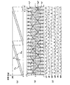
- (A)-(c) is a schematic diagram for explaining an example of processing in a PWM signal generation unit.
- FIG. 2 is a schematic diagram illustrating a configuration of an air conditioner according to Embodiment 1.
- FIG. 7 is a schematic diagram showing a motor and a motor driving device used for an air conditioner according to Embodiment 2.
- FIG. 7 is a schematic diagram illustrating a configuration of an air conditioner according to Embodiment 2.
- FIG. 9 is a schematic diagram showing a modification of the air conditioner according to Embodiment 2. It is a schematic diagram for explaining the opening and closing unit in a modification of the air conditioner according to Embodiment 2.
- FIG. 9 is a schematic diagram showing a motor and a motor driving device used for an air conditioner according to Embodiment 3.
- FIG. 9 is a schematic diagram illustrating a configuration of an air conditioner according to Embodiment 3.
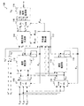
- FIG. 1 is a schematic diagram showing a PMS motor and a motor driving device used for the air conditioner according to the first embodiment.
- This motor driving device is for driving the first PMS motor 141 and the second PMS motor 142.
- the PMS motor may be simply referred to as a motor.
- the illustrated motor driving device includes a rectifier 102, a smoothing unit 103, an inverter 104, an inverter current detecting unit 105, an input voltage detecting unit 106, an induced voltage detecting unit 107, a differential amplifier 108, a control unit 109 And
- Rectifier 102 rectifies an AC voltage from AC power supply 101 to generate a DC voltage.
- the smoothing unit 103 includes a capacitor and the like, smoothes the DC voltage from the rectifier 102, and supplies the DC voltage to the inverter 104.
- the AC power supply 101 is a single-phase power supply in the example of FIG. 1, but may be a three-phase power supply. If the AC power supply 101 has three phases, a three-phase rectifier is used as the rectifier 102.
- the capacitor of the smoothing unit 103 generally, an aluminum electrolytic capacitor having a large capacitance is often used, but a film capacitor having a long life may be used. Further, a configuration may be used in which a harmonic current of a current flowing through the AC power supply 101 is suppressed by using a capacitor having a small capacitance.
- a reactor (not shown) may be inserted between the AC power supply 101 and the smoothing unit 103 to suppress a harmonic current or improve a power factor.
- the inverter 104 generates a three-phase AC voltage having a variable frequency and voltage value from the DC voltage smoothed by the smoothing unit 103.
- a first motor 141 and a second motor 142 are connected in series.
- an IGBT Insulated Gate Bipolar Transistor
- MOSFET Metal Oxide Semiconductor Connector Field Effect Transistor
- a freewheeling diode (not shown) may be connected in parallel to the semiconductor switching element in order to suppress a surge voltage due to switching of the semiconductor switching element.
- a parasitic diode of the semiconductor switching element may be used as a freewheeling diode.
- the same function as the freewheeling diode can be realized by turning the MOSFET on at the timing of the circulation.
- the material forming the semiconductor switching element is not limited to silicon Si, and it is possible to use a wide band gap semiconductor such as silicon carbide SiC, gallium nitride GaN, gallium oxide Ga 2 O 3, diamond, or the like. By using a semiconductor, low loss and high-speed switching can be realized.
- Inverter current detecting section 105 detects a current flowing through inverter 104.
- the inverter current detector 105, the resistance R u to each of the three switching elements of the lower arm of inverter 104 are connected in series, R v, the voltage across V Ru of R w, V Rv, the V Rw Based on this, the current (inverter current) i u_all , iv_all and i w_all of each phase of the inverter 104 is obtained .
- Input voltage detection section 106 detects an input voltage (DC bus voltage) V dc of inverter 104.
- the induced voltage detector 107 detects a combined induced voltage in which the induced voltages of the first motor 141 and the second motor 142 are combined.
- the differential amplifier 108 detects a potential difference between the combined induced voltage detected by the induced voltage detector 107 and a neutral point of the motor winding.
- the control unit 109 operates the inverter 104 based on the current value detected by the inverter current detection unit 105, the voltage value detected by the input voltage detection unit 106, and the potential difference detected by the differential amplifier 108.
- the signal of is output.
- the control unit 109 performs sensorless control based on the induced voltage generated by the first motor 141 and the second motor 142.
- the control unit 109 determines the position of the magnetic pole of the rotor (not shown) of the first motor 141 or the second motor 142 based on the voltage induced by the first motor 141 and the second motor 142. Is estimated, and the first motor 141 and the second motor 142 are controlled via the inverter 104.
- the inverter current detector 105 three resistors R u connected in series with the switching device in the lower arm of inverter 104, R v, the R w, the current of each phase of the inverter 104
- the current of each phase of the inverter 104 is detected by a resistor (not shown) connected between the common connection point of the switching elements of the lower arm and the negative electrode of the capacitor as the smoothing unit 103. May be detected.
- a current detection unit (not shown) may be provided between the inverter 104 and the first motor 141, and the current detection unit may detect the current of each phase of the inverter 104. Further, a current detection unit (not shown) may be provided between the first motor 141 and the second motor 142, and the current detection unit may detect the current of each phase of the inverter 104.
- a current transformer or a Hall element may be used instead of the configuration for calculating the current from the voltage across the resistor.
- the control unit 109 can be realized by a processing circuit.
- the processing circuit may be configured by dedicated hardware using an analog circuit or a digital circuit, may be configured by software, or may be configured by a combination of hardware and software.
- the control unit 109 is configured by a microcomputer having a CPU (Central Processing Unit) or a DSP (Digital Signal Processor).
- the differential amplifier 108 may use a circuit built in a microcomputer or the like constituting the control unit 109. Although only one differential amplifier 108 is shown in FIG. 1 for simplicity, three operational amplifiers are actually used to detect three phases of the combined induced voltage of the motors 141 and 142. Provided.
- the potential difference detected by the differential amplifier 108 is input to the control unit 109, but, for example, the combined induced voltage detected by the induced voltage detection unit 107 may be input to the control unit 109. . In such a case, it is not necessary to provide the differential amplifier 108.
- FIG. 2 is a functional block diagram schematically illustrating a configuration of a part of the control unit 109 that performs sensorless control.
- the control unit 109 performs the sensorless control including coordinate conversion units 110 and 111, speed estimation units 112 and 113, integration units 114 and 115, a voltage command generation unit 116, and an average value calculation unit. 117, a coordinate conversion unit 118, and a PWM signal generation unit 119.
- Coordinate conversion unit 110 uses the first phase estimates of the motor 141 (magnetic pole position estimation value) theta a, a potential difference E U_all from the differential amplifier 108, E v_all, the E W_all, from the stationary three-phase coordinate system and coordinate conversion to the rotating two-phase coordinate system, the induced voltage E d_a in the dq axis of the first motor 141 determines the E q_a.
- Coordinate conversion unit 111 the phase estimate of the second motor 142 with a (magnetic pole position estimation value) theta b, the potential difference E U_all from the differential amplifier 108, E v_all, the E W_all, from the stationary three-phase coordinate system and coordinate conversion to the rotating two-phase coordinate system, the induced voltage E D_B in the dq axis of the second motor 142 determines the E q_b.
- Speed estimating section 112 the induced voltage E d_a in the dq axis of the first motor 141 determines the rotation speed estimation value omega a of the first motor 141 based on the proportional coefficient K e with E q_a and speed.
- the speed estimating section 113, the induced voltage E D_B in the dq axis of the second motor 142 determines the rotation speed estimation value omega b of the second motor 142 based on the E q_b and proportionality coefficient K e.
- a proportional coefficient K e (hereinafter referred to as an induced voltage constant) between the induced voltage of the motor and the rotation speed is stored in advance in the control unit 109, and the induced voltage E on the q axis of each of the motors 141 and 142 is stored.
- K e K e_m ⁇ n.
- Ke_m is an induced voltage constant between the induced voltage and the rotation speed per motor.
- the method of estimating the rotation speed may be any method as long as the rotation speed or the phase can be estimated, and the information used for the calculation is shown here if the rotation speed or the phase can be estimated. There is no problem even if the information is omitted or information other than that shown here is used.
- Integrating unit 114 by integrating the rotational speed estimation value omega a of the first motor 141, obtaining the phase estimate theta a first motor 141.
- the integral unit 115 by integrating the rotational speed estimation value omega b of the second motor 142, obtaining the phase estimate theta b of the second motor 142.
- the output voltage command value is determined. For example, the output voltage command value V q * for the q-axis of the motor 141 and 142, to the target rotation speed omega *, a value obtained by multiplying the induced voltage constant K e, the output voltage command values for the d-axis V d * is , And zero.
- Voltage command generation unit 116 as shown in FIG. 3 (a), the output voltage command value V q * of the q-axis, q-axis of the q-axis induced voltage E q_a and second motor 142 of the first motor 141 difference between the average value E Q_ave of the induced voltage E q_b performs PI control to be zero, to determine the q-axis voltage command value V q **.
- the voltage command generation unit 116 outputs the d-axis output voltage command value V d * , the d-axis induced voltage Ed_a of the first motor 141, and the second motor 142 difference between the average value E D_ave the d-axis induced voltage E D_B performs PI control to be zero, to determine the d-axis voltage command value V d ** of.
- Average value calculating unit 117 calculates the average phase theta ave is the average value of the phase estimate theta b of phase estimates theta a and the second motor 142 of the first motor 141.
- the coordinate conversion unit 118 converts the d-axis voltage command value Vd ** and the q-axis voltage command value Vq ** from a rotating two-phase coordinate system to a stationary three-phase coordinate system based on the average phase ⁇ ave. , Voltage command values v u * , v v * , v w * on the stationary three-phase coordinate system.
- the coordinate conversion unit 118 obtains the applied voltage phase ⁇ v from the average phase ⁇ ave and the dq-axis voltage command values v d * and v q *, and determines the d-axis voltage command value based on the applied voltage phase ⁇ v. Vd ** and the q-axis voltage command value Vq ** are coordinate-transformed from the rotating two-phase coordinate system to the stationary three-phase coordinate system, and the voltage command values vu * , vv * , Find v w * .
- FIG. 4A shows an example of the average phase ⁇ ave , the advance phase angle ⁇ f , and the applied voltage phase ⁇ v , and the voltage command values v u * , v v * , v w * obtained by the coordinate conversion unit 118 . Is shown in FIG. 4 (b).
- the PWM signal generation unit 119 outputs the PWM signals UP, VP, WP, UN, VN, and WN shown in FIG. 4C from the input voltage V dc and the voltage command values v u * , v v * , and v w * . Generate The PWM signals UP, VP, WP, UN, VN, WN are supplied to the inverter 104 and used for controlling the switching elements.
- the inverter 104 controls the ON / OFF of the switching element of the inverter 104 based on the PWM signals UP, VP, WP, UN, VN, and WN, thereby causing the inverter 104 to output an AC voltage having a variable frequency and a variable voltage value.
- the first motor 141 and the second motor 142 are connected to The inverter 104 based on the PWM signals UP, VP, WP, UN, VN, and WN, thereby causing the inverter 104 to output an AC voltage having a variable frequency and a variable voltage value.
- the voltage command values v u * , v v * , and v w * are described as sine waves in FIG. 4, a third harmonic may be superimposed, and the first motor 141 and the second motor Any method can be used as long as the motor 142 can be driven.
- n is an integer of 2 or more PMS motors are controlled in series, the sum of the induced voltages of the PMS motors acting on the inverter is determined by operating one PMS motor. N times as large as In general, when the motor induced voltage when operating the PMS motor in the sensorless control is small, the time for turning on the switching element of the inverter becomes short, and the current detection accuracy and the position estimation accuracy of the PMS motor decrease.
- the magnitude of the induced voltage can be increased n times by connecting a plurality of PMS motors in series. That is, in the present embodiment, the minimum number of revolutions can be reduced to about 1 / n as compared with the case where one PMS motor is conventionally operated.
- two motors 141 and 142 are connected in series to the inverter 104, and therefore, compared to a case where one motor is connected to the inverter, The number of rotations can be reduced to half.
- the control unit 109 is connected in series at a rotation speed lower than the lowest rotation speed which is the lowest rotation speed at which one motor (for example, the motor 141) can be rotated for a predetermined period.
- Two motors 141 and 142 can be operated.
- the predetermined period excludes a period in which the rotation speed of the motors 141 and 142 is temporarily low, such as when the operation of the motor is started or stopped, and is a period having a certain length. It is. Therefore, the predetermined period may be any length that can exclude an instantaneous period.
- the minimum rotation speed when one PMS motor is operated by sensorless control is about 1/10 of the maximum rotation speed at which the PMS motor can be operated, which is determined by the bus voltage of the inverter and the induced voltage constant of the PMS motor. Is a guide. Therefore, by connecting n PMS motors in series, the minimum rotation speed can be reduced to approximately 1 / (10 ⁇ n).
- n PMS motors are connected in series to operate one PMS motor in sensorless control.
- N PMS motors can be operated at a rotation speed R lower than the minimum rotation speed and in the range of R H ⁇ 1 / (10 ⁇ n) ⁇ R ⁇ R H ⁇ 1/10.
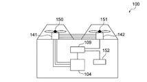
- FIG. 5 is a schematic diagram illustrating a configuration of the air conditioner 100 according to Embodiment 1.
- the air conditioner 100 includes an inverter 104, a control unit 109, motors 141 and 142, fans 150 and 151, and a sensor 152.
- two motors 141 and 142 are connected to one inverter 104.
- a fan 150 is connected to the motor 141, and a fan 151 is connected to the motor 142.
- the fans 150 and 151 are operating units that are driven by receiving power from the motors 141 and 142.
- the motors 141 and 142 generate power.
- the sensor 152 detects a physical quantity indicating at least one of a human activity amount, an indoor temperature, and an outdoor temperature.
- the sensor 152 can be realized by a camera, an infrared sensor, a temperature sensor, or the like.
- the control unit 109 determines that the physical quantity such as the amount of human activity detected by the sensor 152, the indoor temperature, or the outdoor temperature is within a predetermined range, and it is necessary to rapidly change the indoor temperature.
- the motors run out, the motors 141 and 142 are operated at a low speed, so that the fans 150 and 151 are operated at an extremely low speed. This makes it possible to improve the energy saving property or reduce the noise of the fans 150 and 151, and provide a more comfortable space.
- the PMS motors 141 and 142 operate at a low speed, in other words, lower than when one PMS motor is connected. It can be operated at rotation speed.
- the motors 141 and 142 when the physical quantity detected by the sensor is within the predetermined range, the motors 141 and 142 can be operated at a very low rotation speed.
- the physical quantity here is at least one of the amount of human activity, the indoor temperature, and the outdoor temperature, so that the air conditioner 100 according to Embodiment 1 can provide a comfortable space. Become like
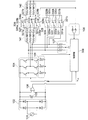
- FIG. FIG. 6 is a schematic diagram showing a motor and a motor driving device used in the air conditioner according to Embodiment 2.
- the illustrated motor driving device includes a rectifier 102, a smoothing unit 103, an inverter 104, an inverter current detecting unit 105, an input voltage detecting unit 106, an induced voltage detecting unit 107, a differential amplifier 108, and a control unit 209. And opening and closing units 220, 221 and 222.
- the motor driving device according to the second embodiment is different from the motor driving device according to the first embodiment in a control unit 209 and opening / closing units 220, 221 and 222.
- opening and closing units 220 and 221 are provided between the first motor 141 and the second motor 142. Further, in the second embodiment, the opening / closing unit 222 for switching the input to the differential amplifier 108 between the subsequent stage of the first motor 141 and the subsequent stage of the second motor 142 is provided.
- the opening / closing units 220, 221 and 222 for switching the connection between the motors 141 and 142 are provided.
- the opening / closing section 220 includes a first terminal 220a, a second terminal 220b, and a third terminal 220c.
- the first terminal 220a is connected to a u-phase output line of the first motor 141.
- the second terminal 220b is connected to a u-phase input line of the second motor 142.
- the third terminal 220c is connected to the opening / closing part 222.
- the opening / closing section 220 can switch the connection with the first terminal 220a between the second terminal 220b and the third terminal 220c according to the instruction from the control section 209.
- the opening / closing section 221 includes a first terminal 221a, a second terminal 221b, and a third terminal 221c.
- the first terminal 221a is connected to a w-phase output line of the first motor 141.
- the second terminal 221b is connected to a w-phase input line of the second motor 142.
- the third terminal 221c is connected to the opening / closing part 222.
- the opening / closing unit 221 can switch the connection with the first terminal 221a between the second terminal 221b and the third terminal 221c in accordance with an instruction from the control unit 209.
- the opening / closing section 222 includes a first terminal 222a, a second terminal 222b, and a third terminal 222c.
- the first terminal 222a is connected to an input line to the differential amplifier 108.
- the second terminal 222b is connected to an output line of the second motor 142.
- the third terminal 222c is connected to the third terminals 220c and 221c of the opening / closing units 220 and 221.
- the opening / closing unit 222 can switch the connection with the first terminal 222a between the second terminal 222b and the third terminal 222c in accordance with an instruction from the control unit 209.
- the first terminals 220a, 221a of the opening / closing portions 220, 221 are connected to the second terminals 220b, 220b, and the first terminal 222a of the opening / closing portion 222 is connected to the second terminal 222b.
- the first motor 141 and the second motor 142 can be connected in series.
- the control unit 209 detects the disconnection from the current value detected by the inverter current detection unit 105. .
- the control unit 209 having detected the disconnection instructs the opening / closing units 220, 221 and 222 to connect the first terminals 220a and 221a of the opening / closing units 220 and 221 to the third terminals 220c and 221c.
- the second motor 142 can be disconnected from the inverter 104, and only the first motor 141 can be operated.
- control unit 209 along with the switching of the number of operating the motor 141 and 142, to change the value of the induced voltage constant K e.
- the value of the induced voltage constant K e are, as the above equations, for example, when the number of operating units becomes one of two is a half value.
- FIG. 7 is a schematic diagram illustrating a configuration of an air conditioner 200 according to Embodiment 2.
- the air conditioner 200 includes an inverter 104, a control unit 209, motors 141 and 142, fans 150 and 151, a sensor 152, and opening / closing units 220, 221 and 222.
- the control unit 209 controls the open / close units 220, 221 and 222 to connect the two motors 141 and 142 to the output side of one inverter 104,
- the connection between the motors 141 can be switched.
- the opening / closing units 220, 221 and 222 function as switching units that switch between a plurality of connections that connect the plurality of motors 141 and 142 and a single connection that connects one motor 141 on the output side of the inverter 104.
- the open / close units 220, 221 and 222 are independently connected to connect one motor 141 when not energizing one motor 142.
- first motor 141 can be operated independently, and the function as air conditioner 200 can be continued. Life extension operation at the time of failure becomes possible.
- the second motor 142 is separated and the first motor 141 can operate independently. However, by changing the configuration of the opening / closing units 220, 221 and 222, the second motor 142 can be operated. The motor 142 may operate alone.
- open / close units 223, 224, and 225 are provided between the inverter 104 and the first motor 141, and the control unit 209 # controls the open / close units 223 and 224. 225 may be controlled so that either one of the first motor 141 and the second motor 142 can be operated independently.
- the opening / closing unit 223 includes a first terminal 223a, a second terminal 223b, and a third terminal 223c.
- the first terminal 223a is connected to the u-phase output line of the inverter 104.
- the second terminal 223b is connected to the first terminal 220a of the opening / closing unit 220.
- the third terminal 223c is connected to the u-phase input line of the first motor 141.
- the opening / closing unit 223 can switch the connection with the first terminal 223a between the second terminal 223b and the third terminal 223c according to an instruction from the control unit 209 #.
- the open / close unit 224 includes a first terminal 224a, a second terminal 224b, and a third terminal 224c.
- the first terminal 224a is connected to a v-phase output line of the inverter 104.
- the second terminal 224b is connected to a v-phase input line of the second motor 142.
- the third terminal 224c is connected to a v-phase input line of the first motor 141.
- the opening / closing unit 224 can switch the connection with the first terminal 224a between the second terminal 224b and the third terminal 224c according to the instruction from the control unit 209 #.
- the opening / closing unit 225 includes a first terminal 225a, a second terminal 225b, and a third terminal 225c.
- the first terminal 225a is connected to a w-phase output line of the inverter 104.
- the second terminal 225b is connected to the first terminal 221a of the opening / closing unit 221.
- the third terminal 225c is connected to a w-phase input line of the first motor 141.
- the opening / closing unit 225 can switch the connection with the first terminal 225a between the second terminal 225b and the third terminal 225c according to an instruction from the control unit 209 #.
- the first terminals 223a, 224a, and 225a of the open / close units 223, 224, and 225 are connected to the third terminals 223c, 224c, and 225c, and the first terminals 220a and 221a of the open / close units 220 and 221 are connected.
- first terminals 223a, 224a, 225a of the opening / closing portions 223, 224, 225 are connected to the second terminals 223b, 224b, 225b, and the first terminals 220a, 221a of the opening / closing portions 220, 221 are connected to the first terminals.
- first terminals 223a, 224a, 225a of the opening / closing portions 223, 224, 225 are connected to the third terminals 223c, 224c, 225c, and the first terminals 220a, 221a of the opening / closing portions 220, 221 are connected to the By connecting to the third terminals 220c and 221c and connecting the first terminal 222a of the opening / closing section 222 to the third terminal 222c, only the first motor 141 can be operated alone.
- the opening / closing sections 220, 221, 222, 223, 224, and 225 are connected to the output side of the inverter 104 by a plurality of motors 141 and 142 connected in series and by a single connection connecting the motor 141 or the motor 142. Function as a switching unit for switching between.
- FIG. 10 is a schematic diagram showing a motor and a motor driving device used for an air conditioner according to Embodiment 3.
- the illustrated motor driving device includes a rectifier 102, a smoothing unit 103, an inverter 104, an inverter current detecting unit 105, an input voltage detecting unit 106, an induced voltage detecting unit 107, a differential amplifier 108, and a control unit 309. And opening / closing parts 326, 327, 328, 329, 330, 331.
- the motor driving device according to the second embodiment is different from the motor driving device according to the first embodiment in a control unit 309 and opening / closing units 326, 327, 328, 329, 330, and 331.
- the opening / closing unit 326 includes a first terminal 326a, a second terminal 326b, and a third terminal 326c.
- the first terminal 326a is connected to the u-phase output line of the first motor 141
- the second terminal 326b is connected to the u-phase input line of the second motor 142
- the third terminal 326c is , The second motor 142. Then, the opening / closing unit 326 switches the connection of the first terminal 326a between the second terminal 326b and the third terminal 326c according to an instruction from the control unit 309.
- the opening / closing unit 327 includes a first terminal 327a, a second terminal 327b, and a third terminal 327c.
- the first terminal 327a is connected to the v-phase output line of the first motor 141
- the second terminal 327b is connected to the v-phase input line of the second motor 142
- the third terminal 327c is , The second motor 142. Then, the opening / closing unit 327 switches the connection of the first terminal 327a between the second terminal 327b and the third terminal 327c according to an instruction from the control unit 309.
- the opening / closing unit 328 includes a first terminal 328a, a second terminal 328b, and a third terminal 328c.
- the first terminal 328a is connected to a w-phase output line of the first motor 141
- the second terminal 328b is connected to a w-phase input line of the second motor 142
- the third terminal 328c is , The second motor 142. Then, the opening / closing unit 328 switches the connection of the first terminal 328a between the second terminal 328b and the third terminal 328c according to an instruction from the control unit 309.
- the opening / closing unit 329 includes a first terminal 329a, a second terminal 329b, and a third terminal 329c.
- the first terminal 329a is connected to the u-phase output line of the inverter 104
- the second terminal 329b is not connected to any line and is open
- the third terminal 329c is connected to the second terminal 329c. It is connected to the u-phase input line of the motor 142. Then, the opening / closing unit 329 switches the connection of the first terminal 329a between the second terminal 329b and the third terminal 329c according to an instruction from the control unit 309.
- the opening / closing unit 330 includes a first terminal 330a, a second terminal 330b, and a third terminal 330c.
- the first terminal 330a is connected to the v-phase output line of the inverter 104
- the second terminal 330b is not connected to any line and is open
- the third terminal 330c is connected to the second terminal 330c. It is connected to the v-phase input line of the motor 142. Then, the opening / closing unit 330 switches the connection of the first terminal 330a between the second terminal 330b and the third terminal 330c according to an instruction from the control unit 309.
- the opening / closing unit 331 includes a first terminal 331a, a second terminal 331b, and a third terminal 331c.
- the first terminal 331a is connected to the w-phase output line of the inverter 104
- the second terminal 331b is not connected to any line, and is open
- the third terminal 331c is connected to the second terminal 331c. It is connected to the w-phase input line of the motor 142.
- the opening / closing unit 331 switches the connection of the first terminal 331a between the second terminal 331b and the third terminal 331c according to an instruction from the control unit 309.
- the maximum operable speed decreases because the induced voltage of the motor increases in proportion to the number of motors operated. If the bus voltage of the inverter is increased, the maximum operable speed can be increased. However, there is a problem that the cost of the booster circuit is increased or the control is complicated.
- FIG. 11 is a schematic diagram illustrating a configuration of an air conditioner 300 according to Embodiment 3.
- the air conditioner 300 includes an inverter 104, a control unit 309, motors 141 and 142, fans 150 and 151, a sensor 152, and opening / closing units 326 to 331.
- the control unit 309 connects the first motor 141 and the second motor 142 in series and , 151 at extremely low speed, it is possible to improve energy saving and reduce noise of the fans 150, 151.
- the control unit 309 connects the first motor 141 and the second motor 142 in parallel, By operating 150 and 151 at high speed, the room temperature can be adjusted more quickly.
- control unit 309 controls the opening / closing units 326 to 331 to operate the plurality of motors 141 and 142 at a rotation speed equal to or higher than a predetermined rotation speed.
- the plurality of motors 141 and 142 are operated at a lower rotation speed than a predetermined rotation speed, the plurality of motors 141 and 142 are connected in series.
- the control unit 309 controls the open / close units 326 to 331 to connect the plurality of motors 141 and 142 in series.
- the plurality of motors 141 and 142 can be operated at a lower rotation speed than the minimum rotation speed that can be rotated for a predetermined period in the parallel connection.
- the predetermined period excludes a period in which the rotation speed of the motors 141 and 142 is temporarily low, such as when the operation of the motor is started or stopped, and is a period having a certain length. It is. Therefore, the predetermined period may be any length that can exclude an instantaneous period.
- the opening / closing units 326 to 331 are connected in series such that the plurality of motors 141 and 142 are connected in series to the output side of the inverter 104, and connected in parallel to connect the plurality of motors 141 and 142 in parallel to the output side of the inverter 104.
- the high-frequency superposition method in which a high-frequency voltage is applied to the motor and the position of the rotor of the motor is estimated using the detected current may be further applied. It is. In such a case, the rotation speed of the motor can be further reduced.
- air conditioners 100 to 300 according to Embodiments 1 to 3 described above the operation units driven by the power from the motors 141 and 142 have been described using the fans 150 and 151 as examples.
- the air conditioners 100 to 300 according to Embodiments 1 to 3 are not limited to such an example.
- air conditioners 100 to 300 according to Embodiments 1 to 3 may include a compressor (not shown) as an operation unit driven by receiving power from motors 141 and 142.
- a compressor is a device that compresses a refrigerant used in an air conditioner.
- the two motors 141 and 142 are connected in series.
- the first to third embodiments are not limited to the two motors 141 and 142.
- Three or more motors may be connected.
- the number of one or more motors connected to each of the plurality of branched paths is made equal. It is desirable.
Landscapes
- Engineering & Computer Science (AREA)
- Power Engineering (AREA)
- Chemical & Material Sciences (AREA)
- Combustion & Propulsion (AREA)
- Mechanical Engineering (AREA)
- General Engineering & Computer Science (AREA)
- Control Of Multiple Motors (AREA)
- Control Of Motors That Do Not Use Commutators (AREA)
Abstract
直流電圧から三相交流電圧を生成する1台のインバータ(104)と、インバータ(104)の出力側に直列に接続されて動力を発生するn台(nは2以上の整数)のモータ(141、142)と、その動力を受けて駆動される動作部と、n台のモータ(141、142)による誘起電圧に基づいてセンサレス制御を行う制御部(109)とを備える。
Description
本発明は、空調機に関する。
永久磁石同期モータ(PMSモータ)を運転するためには、PMSモータの回転子の磁極位置に応じて電流と電圧とを制御する必要がある。磁極位置を検出するために、エンコーダ又はホールセンサ等の位置検出器を使う場合がある。しかしながら、位置検出器を使うことで、コストアップ又はモータの大型化といった問題が発生する。
このため、例えば、特許文献1は、PMSモータの回転子の磁極位置を推定して、PMSモータを制御するセンサレス制御を行うモータ駆動制御装置を開示している。このセンサレス制御では、PMSモータの永久磁石の磁束による回転時の誘起電圧を利用して、PMSモータの回転子の位置を推定する方法が広く知られている。
空調機においては、近年の断熱技術の向上又は熱交換器の性能向上に伴い、温度調整の対象となる空間の温度が所望の値にある程度安定すると、ファン又は圧縮機を低速で運転させることで省エネ性を向上させている。
しかしながら、従来のセンサレス制御では、誘起電圧が小さい低速回転時において、位置推定精度が低下してしまい、PMSモータを低速で運転することができないという課題がある。
そこで、本発明の1又は複数の態様は、センサレス制御において、PMSモータを低速で運転することができるようにすることを目的とする。
本発明の第1の態様に係る空調機は、直流電圧から三相交流電圧を生成する1台のインバータと、前記インバータの出力側に直列に接続されて動力を発生するn台(nは2以上の整数)のモータと、前記動力を受けて駆動される動作部と、前記n台のモータによる誘起電圧に基づいてセンサレス制御を行う制御部と、を備えることを特徴とする。
本発明の第2の態様に係る空調機は、直流電圧から三相交流電圧を生成する1台のインバータと、前記三相交流電圧を受けて動力を発生する2台のモータと、前記2台のモータを前記インバータの出力側に直列に接続する複数接続と、前記2台のモータの内の一方のモータのみを前記インバータの出力側に接続する単独接続とを切り替える切替部と、前記動力を受けて駆動される動作部と、前記複数接続時には、前記2台のモータによる誘起電圧に基づいて、前記単独接続時には、前記一方のモータによる誘起電圧に基づいて、センサレス制御を行う制御部と、を備えることを特徴とする。
本発明の第3の態様に係る空調機は、直流電圧から三相交流電圧を生成する1台のインバータと、前記三相交流電圧を受けて動力を発生するn台(nは2以上の整数)のモータと、前記n台のモータを前記インバータの出力側に直列に接続する直列接続と、前記n台のモータを前記インバータの出力側に並列に接続する並列接続とを切り替える切替部と、前記動力を受けて駆動される動作部と、前記n台のモータによる誘起電圧に基づいてセンサレス制御を行う制御部と、を備えることを特徴とする。
本発明の1又は複数の態様によれば、センサレス制御において、PMSモータを低速で運転することができる。
以下に添付図面を参照し、実施の形態に係る空調機について説明する。なお、以下に示す実施の形態により本発明が限定されるものではない。
実施の形態1.
図1は、実施の形態1に係る空調機に使用されるPMSモータ及びモータ駆動装置を示す概略図である。このモータ駆動装置は、第1のPMSモータ141及び第2のPMSモータ142を駆動するためのものである。なお、以下では、PMSモータを単にモータという場合がある。
図1は、実施の形態1に係る空調機に使用されるPMSモータ及びモータ駆動装置を示す概略図である。このモータ駆動装置は、第1のPMSモータ141及び第2のPMSモータ142を駆動するためのものである。なお、以下では、PMSモータを単にモータという場合がある。
図示のモータ駆動装置は、整流器102と、平滑部103と、インバータ104と、インバータ電流検出部105と、入力電圧検出部106と、誘起電圧検出部107と、差動アンプ108と、制御部109とを備える。
整流器102は、交流電源101からの交流電圧を整流して直流電圧を生成する。
平滑部103は、コンデンサ等で構成され、整流器102からの直流電圧を平滑してインバータ104に供給する。
平滑部103は、コンデンサ等で構成され、整流器102からの直流電圧を平滑してインバータ104に供給する。
なお、交流電源101は、図1の例では単相であるが、三相電源でもよい。交流電源101が三相であれば、整流器102としても三相の整流器が用いられる。
平滑部103のコンデンサとしては、一般的には静電容量の大きなアルミ電解コンデンサを用いることが多いが、長寿命であるフィルムコンデンサを用いてもよい。さらに静電容量の小さなコンデンサを用いることで、交流電源101に流れる電流の高調波電流を抑制するよう構成してもよい。
また、交流電源101から平滑部103までの間に高調波電流の抑制又は力率の改善のためにリアクトル(図示せず)を挿入してもよい。
インバータ104は、平滑部103で平滑された直流電圧から、周波数及び電圧値が可変の三相交流電圧を生成する。インバータ104の出力側には、第1のモータ141と、第2のモータ142とが直列に接続されている。
インバータ104を構成する半導体スイッチング素子としては、IGBT(Insulated Gate Bipolar Transistor)又はMOSFET(Metal Oxide Semiconductor Field Effect Transistor)が用いられることが多い。
なお、半導体スイッチング素子のスイッチングによるサージ電圧を抑制する目的で環流ダイオード(図示せず)を半導体スイッチング素子に並列に接続した構成としてもよい。半導体スイッチング素子の寄生ダイオードを還流ダイオードとして用いてもよい。MOSFETの場合は、環流のタイミングでMOSFETをON状態とすることにより、還流ダイオードと同様の機能を実現することが可能である。
半導体スイッチング素子を構成する材料は、ケイ素Siに限定されず、ワイドバンドギャップ半導体である炭化ケイ素SiC、窒化ガリウムGaN、酸化ガリウムGa2O3又はダイヤモンド等を用いることが可能であり、ワイドバンドギャップ半導体を用いることで、低損失化及び高速スイッチング化を実現することが可能となる。
インバータ電流検出部105は、インバータ104に流れる電流を検出する。図示の例では、インバータ電流検出部105は、インバータ104の3つの下アームのスイッチング素子にそれぞれ直列に接続された抵抗Ru、Rv、Rwの両端電圧VRu、VRv、VRwに基づいて、インバータ104のそれぞれの相の電流(インバータ電流)iu_all、iv_all、iw_allを求める。
入力電圧検出部106は、インバータ104の入力電圧(直流母線電圧)Vdcを検出する。
誘起電圧検出部107は、第1のモータ141及び第2のモータ142による誘起電圧が合成された合成誘起電圧を検出する。
差動アンプ108は、誘起電圧検出部107で検出された合成誘起電圧と、モータ巻線の中性点との電位差を検出する。
誘起電圧検出部107は、第1のモータ141及び第2のモータ142による誘起電圧が合成された合成誘起電圧を検出する。
差動アンプ108は、誘起電圧検出部107で検出された合成誘起電圧と、モータ巻線の中性点との電位差を検出する。
制御部109は、インバータ電流検出部105で検出された電流値、入力電圧検出部106で検出された電圧値、及び、差動アンプ108で検出された電位差に基づいて、インバータ104を動作させるための信号を出力する。例えば、制御部109は、第1のモータ141及び第2のモータ142による誘起電圧に基づいてセンサレス制御を行う。具体的には、制御部109は、第1のモータ141及び第2のモータ142による誘起電圧に基づいて、第1のモータ141又は第2のモータ142の回転子(図示せず)の磁極位置を推定して、インバータ104を介して、第1のモータ141及び第2のモータ142を制御する。
なお、上記の例では、インバータ電流検出部105が、インバータ104の下アームのスイッチング素子に直列に接続された3つの抵抗Ru,Rv,Rwにより、インバータ104のそれぞれの相の電流を検出するが、代わりに、下アームのスイッチング素子の共通接続点と平滑部103としてのコンデンサの負側電極との間に接続された抵抗(図示せず)により、インバータ104のそれぞれの相の電流を検出するものであってもよい。
また、インバータ104と、第1のモータ141との間に電流検出部(図示せず)を設けて、この電流検出部により、インバータ104のそれぞれの相の電流を検出してもよい。
さらに、第1のモータ141と第2のモータ142との間に電流検出部(図示せず)を設けて、この電流検出部により、インバータ104のそれぞれの相の電流を検出してもよい。
さらに、第1のモータ141と第2のモータ142との間に電流検出部(図示せず)を設けて、この電流検出部により、インバータ104のそれぞれの相の電流を検出してもよい。
電流の検出には、抵抗の両端電圧から電流を算出する構成の代わりに、カレントトランス又はホール素子等を用いてもよい。
制御部109は、処理回路で実現可能である。処理回路は、アナログ回路又はデジタル回路等を用いた専用のハードウェアで構成されていてもよく、ソフトウェアで構成されていてもよく、ハードウェアとソフトウェアとの組み合せで構成されていてもよい。ソフトウェアで構成される場合、制御部109は、CPU(Central Processing Unit)を備えたマイクロコンピュータ又はDSP(Digital Signal Processor)等で構成される。
差動アンプ108は、制御部109を構成するマイコン等に内蔵された回路を用いてもよい。なお、簡略化のため、図1では、1つの差動アンプ108のみが示されているが、モータ141、142の合成誘起電圧の三相分を検出するため、実際には3つの作動アンプが備えられている。
また、図1では、差動アンプ108で検出された電位差が制御部109に入力されているが、例えば、誘起電圧検出部107で検出された合成誘起電圧が制御部109に入力されてもよい。このような場合には、差動アンプ108を設ける必要がなくなる。
図2は、制御部109のセンサレス制御を行う部分の構成を概略的に示す機能ブロック図である。
図示のように、制御部109のセンサレス制御を行う部分は、座標変換部110、111と、速度推定部112、113と、積分部114、115と、電圧指令生成部116と、平均値算出部117と、座標変換部118と、PWM信号生成部119とを有する。
図示のように、制御部109のセンサレス制御を行う部分は、座標変換部110、111と、速度推定部112、113と、積分部114、115と、電圧指令生成部116と、平均値算出部117と、座標変換部118と、PWM信号生成部119とを有する。
座標変換部110は、第1のモータ141の位相推定値(磁極位置推定値)θaを用いて、差動アンプ108からの電位差Eu_all、Ev_all、Ew_allを、静止三相座標系から回転二相座標系に座標変換して、第1のモータ141のdq軸における誘起電圧Ed_a、Eq_aを求める。
座標変換部111は、第2のモータ142の位相推定値(磁極位置推定値)θbを用いて、差動アンプ108からの電位差Eu_all、Ev_all、Ew_allを、静止三相座標系から回転二相座標系に座標変換して、第2のモータ142のdq軸における誘起電圧Ed_b、Eq_bを求める。
速度推定部112は、第1のモータ141のdq軸における誘起電圧Ed_a、Eq_a及び回転数との比例係数Keに基づいて第1のモータ141の回転数推定値ωaを求める。
同様に、速度推定部113は、第2のモータ142のdq軸における誘起電圧Ed_b、Eq_b及び比例係数Keに基づいて第2のモータ142の回転数推定値ωbを求める。
同様に、速度推定部113は、第2のモータ142のdq軸における誘起電圧Ed_b、Eq_b及び比例係数Keに基づいて第2のモータ142の回転数推定値ωbを求める。
なお、回転数の推定方法については、例えば、モータの誘起電圧の大きさと回転数とが比例の関係にあることを用いればよい。具体的には、モータの誘起電圧と回転数との比例係数Ke(以下、誘起電圧定数という)を予め制御部109に記憶しておき、各モータ141、142のq軸上の誘起電圧Ed_a、Eq_a、Ed_b、Eq_bを、それぞれ誘起電圧定数Keで除すれば、およその回転数を推定することができる。
ここで、誘起電圧定数Keの大きさは、直列に接続されたn台のモータがそれぞれ同じ仕様であれば、Ke=Ke_m×nとすればよい。値Ke_mは、モータ1台あたりの誘起電圧と回転数との誘起電圧定数である。
なお、回転数の推定方法は、回転数又は位相が推定可能な方式であればどのような方式でもよく、また、演算に使用する情報は、回転数又は位相が推定可能であれば、今回示した情報を省いても、また今回示した以外の情報を用いても何ら問題ない。
積分部114は、第1のモータ141の回転数推定値ωaを積分することで、第1のモータ141の位相推定値θaを求める。
同様に、積分部115は、第2のモータ142の回転数推定値ωbを積分することで、第2のモータ142の位相推定値θbを求める。
同様に、積分部115は、第2のモータ142の回転数推定値ωbを積分することで、第2のモータ142の位相推定値θbを求める。
続いて、出力電圧指令値を決定する。例えば、モータ141、142のq軸に対する出力電圧指令値Vq
*は、目標となる回転数ω*に、誘起電圧定数Keを乗じた値とし、d軸に対する出力電圧指令値Vd
*は、ゼロとする。
電圧指令生成部116は、図3(a)に示すように、q軸の出力電圧指令値Vq
*と、第1のモータ141のq軸誘起電圧Eq_a及び第2のモータ142のq軸誘起電圧Eq_bの平均値Eq_aveとの差分がゼロになるようにPI制御を行い、q軸電圧指令値Vq
**を決定する。
同様に、電圧指令生成部116は、図3(b)に示すように、d軸の出力電圧指令値Vd
*と、第1のモータ141のd軸誘起電圧Ed_a及び第2のモータ142のd軸誘起電圧Ed_bの平均値Ed_aveとの差分がゼロになるようにPI制御を行い、d軸電圧指令値Vd
**を決定する。
平均値算出部117は、第1のモータ141のq軸誘起電圧Eq_a及び第2のモータ142のq軸誘起電圧Eq_bの平均値Eq_ave、並びに、第1のモータ141のd軸誘起電圧Ed_a及び第2のモータ142のd軸誘起電圧Ed_bの平均値Ed_aveを算出する。
また、平均値算出部117は、第1のモータ141の位相推定値θa及び第2のモータ142の位相推定値θbの平均値である平均位相θaveを算出する。
また、平均値算出部117は、第1のモータ141の位相推定値θa及び第2のモータ142の位相推定値θbの平均値である平均位相θaveを算出する。
座標変換部118は、平均位相θaveに基づき、d軸電圧指令値Vd
**及びq軸電圧指令値Vq
**を、回転二相座標系から静止三相座標系に座標変換して、静止三相座標系上の電圧指令値vu
*、vv
*、vw
*を求める。
例えば、座標変換部118は、平均位相θaveと、dq軸電圧指令値vd
*、vq
*とから、印加電圧位相θvを求め、印加電圧位相θvに基づき、d軸電圧指令値Vd
**及びq軸電圧指令値Vq
**を回転二相座標系から静止三相座標系に座標変換して、静止三相座標系上の電圧指令値vu
*、vv
*、vw
*を求める。
印加電圧位相θvは、例えば、dq軸電圧指令値vd
*、vq
*から、θf=tan-1(vq
*/vd
*)により得られる進み位相角θfを、平均位相θaveに加算することで得られる。
平均位相θave、進み位相角θf、及び印加電圧位相θvの例が図4(a)に示され、座標変換部118で求められる電圧指令値vu
*、vv
*、vw
*の例が図4(b)に示されている。
PWM信号生成部119は、入力電圧Vdcと、電圧指令値vu
*、vv
*、vw
*とから図4(c)に示されるPWM信号UP、VP、WP、UN、VN、WNを生成する。PWM信号UP、VP、WP、UN、VN、WNは、インバータ104に供給され、スイッチング素子の制御に用いられる。
インバータ104では、PWM信号UP、VP、WP、UN、VN、WNに基づいてインバータ104のスイッチング素子のON/OFFを制御することで、インバータ104から周波数及び電圧値が可変の交流電圧を出力させ、第1のモータ141及び第2のモータ142に印加することができる。
なお、電圧指令値vu
*、vv
*、vw
*については、図4中では正弦波として説明しているが、三次高調波を重畳させてもよく、第1のモータ141及び第2のモータ142を駆動可能であれば方式は問わない。
ここで、前述したようにn台(nは2以上の整数)のPMSモータを直列に制御するため、インバータに対して作用する各PMSモータの誘起電圧の合計は、1台のPMSモータを運転する場合のn倍となる。一般に、センサレス制御にてPMSモータを運転する際のモータ誘起電圧が小さいと、インバータのスイッチング素子をONにする時間が短くなり、PMSモータの電流検出精度及び位置推定精度が低下する。
本実施の形態においては、複数のPMSモータを直列接続することで、誘起電圧の大きさをn倍にすることができる。すなわち、従来1台のPMSモータで運転した場合に比べて、本実施の形態は、最低回転数をおよそ1/nまで下げることが可能となる。
本実施の形態では、図1に示されているように、二つのモータ141、142が直列でインバータ104に接続されているため、一つのモータがインバータに接続されている場合に比べて、最低回転数を1/2まで下げることができる。これにより、制御部109は、1台のモータ(例えば、モータ141)を予め定められた期間回転させることのできる最も低い回転数である最低回転数よりも低い回転数で、直列に接続された2台のモータ141、142を運転することができる。予め定められた期間は、モータの運転開始時又は運転停止時のように、モータ141、142の回転数が一時的に低回転となる期間を除くものであって、ある程度の長さのある期間である。このため、予め定められた期間としては、瞬間的な期間を除くことのできる任意の長さが定められていればよい。
また、1台のPMSモータをセンサレス制御で運転する場合の最低回転数は、インバータの母線電圧とPMSモータの誘起電圧定数とから決まる、PMSモータを運転可能な最高回転数のおよそ1/10程度が目安となる。このため、n台のPMSモータを直列に接続することで、1/(10×n)程度の回転数まで、最低回転数を下げることができる。
このため、PMSモータを運転可能な最高回転数をRHとすると、本実施の形態では、n台のPMSモータを直列に接続することで、1台のPMSモータをセンサレス制御で運転する場合の最低回転数よりも低い、RH×1/(10×n)≦R<RH×1/10の範囲の回転数Rで、n台のPMSモータを運転することができる。
ここで、図1に示されているモータ141、142及びモータ駆動装置を空調機のファンに適用した場合について説明する。
図5は、実施の形態1に係る空調機100の構成を示す概略図である。
空調機100は、インバータ104、制御部109、モータ141、142、ファン150、151及びセンサ152を備える。
図5は、実施の形態1に係る空調機100の構成を示す概略図である。
空調機100は、インバータ104、制御部109、モータ141、142、ファン150、151及びセンサ152を備える。
図5に示されているように、1台のインバータ104に対して、2台のモータ141、142が接続されている。モータ141には、ファン150が接続され、モータ142には、ファン151が接続されている。言い換えると、ファン150、151は、モータ141、142から動力を得て駆動される動作部である。モータ141、142は、動力を発生する。
センサ152は、人の活動量、室内の温度及び室外の温度の少なくとも1つを示す物理量を検出する。例えば、センサ152は、カメラ、赤外線センサ又は温度センサ等により実現することができる。
そして、制御部109は、センサ152にて検出した人の活動量、室内の温度、又は、室外の温度といった物理量が、予め定められた範囲内にあり、室内の温度を急激に変更する必要がなくなった場合において、モータ141、142を低速運転することにより、ファン150、151を極低速で運転する。このことで、省エネ性の向上又はファン150、151の騒音低減を図ることが可能となり、より快適な空間を提供することができる。
なお、ここでいう極低速とは、1台のモータを運転可能な最高回転数の1/10よりも低く、その極低速は、その最高回転数の1/(n×10)以上の回転数であることが、望ましい。図1では、n=2である。
以上のように、実施の形態1に係る空調機100によれば、センサレス制御において、PMSモータ141、142を低速で運転すること、言い換えると、1つのPMSモータが接続されている場合よりも低い回転数で運転することができる。
実施の形態1に係る空調機100によれば、センサで検出される物理量が予め定められた範囲内である場合に、非常に低い回転数で、モータ141、142を運転することができる。
ここでの物理量は、人の活動量、室内の温度、及び、室外の温度の少なくとも何れか1つとすることで、実施の形態1に係る空調機100により、快適な空間を提供することができるようになる。
実施の形態2.
図6は、実施の形態2に係る空調機に使用されるモータ及びモータ駆動装置を示す概略図である。
図示のモータ駆動装置は、整流器102と、平滑部103と、インバータ104と、インバータ電流検出部105と、入力電圧検出部106と、誘起電圧検出部107と、差動アンプ108と、制御部209と、開閉部220、221、222とを備える。
実施の形態2におけるモータ駆動装置は、制御部209及び開閉部220、221、222において、実施の形態1におけるモータ駆動装置と異なっている。
図6は、実施の形態2に係る空調機に使用されるモータ及びモータ駆動装置を示す概略図である。
図示のモータ駆動装置は、整流器102と、平滑部103と、インバータ104と、インバータ電流検出部105と、入力電圧検出部106と、誘起電圧検出部107と、差動アンプ108と、制御部209と、開閉部220、221、222とを備える。
実施の形態2におけるモータ駆動装置は、制御部209及び開閉部220、221、222において、実施の形態1におけるモータ駆動装置と異なっている。
図6に示されているように、実施の形態2では、第1のモータ141と第2のモータ142との間に、開閉部220、221が設けられている。
また、実施の形態2では、差動アンプ108への入力を、第1のモータ141の後段と、第2のモータ142の後段との間で切り替えるための開閉部222が設けられている。
また、実施の形態2では、差動アンプ108への入力を、第1のモータ141の後段と、第2のモータ142の後段との間で切り替えるための開閉部222が設けられている。
複数のモータが直列に接続されている場合、どれか1つのモータが、例えば、断線による故障を引き起こすと、電流経路が形成されず、全てのモータが停止してしまう。そこで実施の形態2では、モータ141、142間の接続を切替えるための開閉部220、221、222が設けられている。
開閉部220は、第1の端子220aと、第2の端子220bと、第3の端子220cとを備える。第1の端子220aは、第1のモータ141のu相の出力線に接続されている。第2の端子220bは、第2のモータ142のu相の入力線に接続されている。第3の端子220cは、開閉部222に接続されている。
そして、開閉部220は、制御部209からの指示に従って、第1の端子220aとの接続を、第2の端子220bと、第3の端子220cとの間で切り替えることができる。
同様に、開閉部221は、第1の端子221aと、第2の端子221bと、第3の端子221cとを備える。第1の端子221aは、第1のモータ141のw相の出力線に接続されている。第2の端子221bは、第2のモータ142のw相の入力線に接続されている。第3の端子221cは、開閉部222に接続されている。
そして、開閉部221は、制御部209からの指示に従って、第1の端子221aとの接続を、第2の端子221bと、第3の端子221cとの間で切り替えることができる。
開閉部222は、第1の端子222aと、第2の端子222bと、第3の端子222cとを備える。第1の端子222aは、差動アンプ108への入力線に接続されている。第2の端子222bは、第2のモータ142の出力線に接続されている。第3の端子222cは、開閉部220、221の第3の端子220c、221cに接続されている。
そして、開閉部222は、制御部209からの指示に従って、第1の端子222aとの接続を、第2の端子222bと、第3の端子222cとの間で切り替えることができる。
実施の形態2では、開閉部220、221の第1の端子220a、221aを、第2の端子220b、220bに接続し、開閉部222の第1の端子222aを、第2の端子222bに接続することで、第1のモータ141と、第2のモータ142とを直列に接続することができる。
このような状態において、例えば、第2のモータ142の断線により、モータ141、142に電流が流れなくなった場合、制御部209は、インバータ電流検出部105で検出された電流値から断線を検出する。
断線を検出した制御部209は、開閉部220、221、222に指示することで、開閉部220、221の第1の端子220a、221aを、第3の端子220c、221cに接続し、開閉部222の第1の端子222aを、第3の端子222cに接続することで、第2のモータ142をインバータ104から切り離し、第1のモータ141のみを動作させることができる。
ここで、制御部209では、モータ141、142の運転台数の切り替えに伴い、誘起電圧定数Keの値を変更する。誘起電圧定数Keの値は、前述の式が示すように、例えば、運転台数が2台から1台となった場合には、半分の値となる。
ここで、図6に示されているモータ141、142及びモータ駆動装置を空調機のファンに適用した場合について説明する。
図7は、実施の形態2に係る空調機200の構成を示す概略図である。
空調機200は、インバータ104、制御部209、モータ141、142、ファン150、151、センサ152及び開閉部220、221、222を備える。
図7は、実施の形態2に係る空調機200の構成を示す概略図である。
空調機200は、インバータ104、制御部209、モータ141、142、ファン150、151、センサ152及び開閉部220、221、222を備える。
図7に示されているように、制御部209は、開閉部220、221、222を制御することで、1台のインバータ104の出力側に、2台のモータ141、142の接続と、1台のモータ141の接続とを切り替えることができる。言い換えると、開閉部220、221、222は、インバータ104の出力側に、複数のモータ141、142を接続する複数接続と、1台のモータ141を接続する単独接続とを切り替える切替部として機能する。例えば、開閉部220、221、222は、1台のモータ142に通電を行わない場合に、1台のモータ141を接続する単独接続とする。
図7のように配線することで、配線の無駄な引き回しを抑制でき、基板側に開閉部220、221、222を設ける場合よりもモータ141、142の効率悪化又はノイズ悪化を抑制できる。
実施の形態2によれば、第2のモータ142が故障した場合においても、第1のモータ141を単独で運転することができ、空調機200としての機能を継続することができるため、ファン151故障時の延命運転が可能となる。
なお、実施の形態2では、第2のモータ142を切り離し、第1のモータ141を単独で動作できるようになっているが、開閉部220、221、222の構成を変更することで、第2のモータ142を単独で動作できるようにしてもよい。
また、例えば、図8に示されているように、インバータ104と、第1のモータ141との間に、開閉部223、224、225を設けて、制御部209#により、開閉部223、224、225を制御することで、第1のモータ141及び第2のモータ142の何れか一方を単独で動作させることができるようにしてもよい。
具体的には、図9に示されているように、開閉部223は、第1の端子223aと、第2の端子223bと、第3の端子223cとを備える。第1の端子223aは、インバータ104のu相の出力線に接続されている。第2の端子223bは、開閉部220の第1の端子220aに接続されている。第3の端子223cは、第1のモータ141のu相の入力線に接続されている。
そして、開閉部223は、制御部209#からの指示に従って、第1の端子223aとの接続を、第2の端子223bと、第3の端子223cとの間で切り替えることができる。
同様に、開閉部224は、第1の端子224aと、第2の端子224bと、第3の端子224cとを備える。第1の端子224aは、インバータ104のv相の出力線に接続されている。第2の端子224bは、第2のモータ142のv相の入力線に接続されている。第3の端子224cは、第1のモータ141のv相の入力線に接続されている。
そして、開閉部224は、制御部209#からの指示に従って、第1の端子224aとの接続を、第2の端子224bと、第3の端子224cとの間で切り替えることができる。
開閉部225は、第1の端子225aと、第2の端子225bと、第3の端子225cとを備える。第1の端子225aは、インバータ104のw相の出力線に接続されている。第2の端子225bは、開閉部221の第1の端子221aに接続されている。第3の端子225cは、第1のモータ141のw相の入力線に接続されている。
そして、開閉部225は、制御部209#からの指示に従って、第1の端子225aとの接続を、第2の端子225bと、第3の端子225cとの間で切り替えることができる。
この変形例では、開閉部223、224、225の第1の端子223a、224a、225aを、第3の端子223c、224c、225cに接続し、開閉部220、221の第1の端子220a、221aを、第2の端子220b、221bに接続し、開閉部222の第1の端子222aを、第2の端子222bに接続することで、第1のモータ141と、第2のモータ142とを直列に接続することができる。
また、開閉部223、224、225の第1の端子223a、224a、225aを、第2の端子223b、224b、225bに接続し、開閉部220、221の第1の端子220a、221aを、第2の端子220b、221bに接続し、開閉部222の第1の端子222aを、第2の端子222bに接続することで、第2のモータ142のみを単独で動作させることができる。
さらに、開閉部223、224、225の第1の端子223a、224a、225aを、第3の端子223c、224c、225cに接続し、開閉部220、221の第1の端子220a、221aを、第3の端子220c、221cに接続し、開閉部222の第1の端子222aを、第3の端子222cに接続することで、第1のモータ141のみを単独で動作させることができる。
言い換えると、開閉部220、221、222、223、224、225は、インバータ104の出力側に、複数のモータ141、142を直列で接続する複数接続と、モータ141又はモータ142を接続する単独接続とを切り替える切替部として機能する。
実施の形態3.
図10は、実施の形態3に係る空調機に使用されるモータ及びモータ駆動装置を示す概略図である。
図示のモータ駆動装置は、整流器102と、平滑部103と、インバータ104と、インバータ電流検出部105と、入力電圧検出部106と、誘起電圧検出部107と、差動アンプ108と、制御部309と、開閉部326、327、328、329、330、331とを備える。
実施の形態2におけるモータ駆動装置は、制御部309及び開閉部326、327、328、329、330、331において、実施の形態1におけるモータ駆動装置と異なっている。
図10は、実施の形態3に係る空調機に使用されるモータ及びモータ駆動装置を示す概略図である。
図示のモータ駆動装置は、整流器102と、平滑部103と、インバータ104と、インバータ電流検出部105と、入力電圧検出部106と、誘起電圧検出部107と、差動アンプ108と、制御部309と、開閉部326、327、328、329、330、331とを備える。
実施の形態2におけるモータ駆動装置は、制御部309及び開閉部326、327、328、329、330、331において、実施の形態1におけるモータ駆動装置と異なっている。
開閉部326は、第1の端子326aと、第2の端子326bと、第3の端子326cとを備える。
第1の端子326aは、第1のモータ141のu相の出力線に接続され、第2の端子326bは、第2のモータ142のu相の入力線に接続され、第3の端子326cは、第2のモータ142の出力線に接続されている。
そして、開閉部326は、制御部309からの指示に従って、第1の端子326aの接続を、第2の端子326bと、第3の端子326cとの間で切り替える。
第1の端子326aは、第1のモータ141のu相の出力線に接続され、第2の端子326bは、第2のモータ142のu相の入力線に接続され、第3の端子326cは、第2のモータ142の出力線に接続されている。
そして、開閉部326は、制御部309からの指示に従って、第1の端子326aの接続を、第2の端子326bと、第3の端子326cとの間で切り替える。
開閉部327は、第1の端子327aと、第2の端子327bと、第3の端子327cとを備える。
第1の端子327aは、第1のモータ141のv相の出力線に接続され、第2の端子327bは、第2のモータ142のv相の入力線に接続され、第3の端子327cは、第2のモータ142の出力線に接続されている。
そして、開閉部327は、制御部309からの指示に従って、第1の端子327aの接続を、第2の端子327bと、第3の端子327cとの間で切り替える。
第1の端子327aは、第1のモータ141のv相の出力線に接続され、第2の端子327bは、第2のモータ142のv相の入力線に接続され、第3の端子327cは、第2のモータ142の出力線に接続されている。
そして、開閉部327は、制御部309からの指示に従って、第1の端子327aの接続を、第2の端子327bと、第3の端子327cとの間で切り替える。
開閉部328は、第1の端子328aと、第2の端子328bと、第3の端子328cとを備える。
第1の端子328aは、第1のモータ141のw相の出力線に接続され、第2の端子328bは、第2のモータ142のw相の入力線に接続され、第3の端子328cは、第2のモータ142の出力線に接続されている。
そして、開閉部328は、制御部309からの指示に従って、第1の端子328aの接続を、第2の端子328bと、第3の端子328cとの間で切り替える。
第1の端子328aは、第1のモータ141のw相の出力線に接続され、第2の端子328bは、第2のモータ142のw相の入力線に接続され、第3の端子328cは、第2のモータ142の出力線に接続されている。
そして、開閉部328は、制御部309からの指示に従って、第1の端子328aの接続を、第2の端子328bと、第3の端子328cとの間で切り替える。
開閉部329は、第1の端子329aと、第2の端子329bと、第3の端子329cとを備える。
第1の端子329aは、インバータ104のu相の出力線に接続され、第2の端子329bは、何れの線にも接続されず、開放されており、第3の端子329cは、第2のモータ142のu相の入力線に接続されている。
そして、開閉部329は、制御部309からの指示に従って、第1の端子329aの接続を、第2の端子329bと、第3の端子329cとの間で切り替える。
第1の端子329aは、インバータ104のu相の出力線に接続され、第2の端子329bは、何れの線にも接続されず、開放されており、第3の端子329cは、第2のモータ142のu相の入力線に接続されている。
そして、開閉部329は、制御部309からの指示に従って、第1の端子329aの接続を、第2の端子329bと、第3の端子329cとの間で切り替える。
開閉部330は、第1の端子330aと、第2の端子330bと、第3の端子330cとを備える。
第1の端子330aは、インバータ104のv相の出力線に接続され、第2の端子330bは、何れの線にも接続されず、開放されており、第3の端子330cは、第2のモータ142のv相の入力線に接続されている。
そして、開閉部330は、制御部309からの指示に従って、第1の端子330aの接続を、第2の端子330bと、第3の端子330cとの間で切り替える。
第1の端子330aは、インバータ104のv相の出力線に接続され、第2の端子330bは、何れの線にも接続されず、開放されており、第3の端子330cは、第2のモータ142のv相の入力線に接続されている。
そして、開閉部330は、制御部309からの指示に従って、第1の端子330aの接続を、第2の端子330bと、第3の端子330cとの間で切り替える。
開閉部331は、第1の端子331aと、第2の端子331bと、第3の端子331cとを備える。
第1の端子331aは、インバータ104のw相の出力線に接続され、第2の端子331bは、何れの線にも接続されず、開放されており、第3の端子331cは、第2のモータ142のw相の入力線に接続されている。
そして、開閉部331は、制御部309からの指示に従って、第1の端子331aの接続を、第2の端子331bと、第3の端子331cとの間で切り替える。
第1の端子331aは、インバータ104のw相の出力線に接続され、第2の端子331bは、何れの線にも接続されず、開放されており、第3の端子331cは、第2のモータ142のw相の入力線に接続されている。
そして、開閉部331は、制御部309からの指示に従って、第1の端子331aの接続を、第2の端子331bと、第3の端子331cとの間で切り替える。
以上のような構成において、開閉部326~331の第1の端子326a~331aを第2の端子326b~331bに接続させた場合には、第1のモータ141と第2のモータ142とは、直列に接続される。一方、開閉部326~331の第1の端子326a~331aを第3の端子326c~331cに接続させた場合には、第1のモータ141と第2のモータ142とは、並列に接続される。
なお、制御部309ではモータ141、142の接続方式の切り替えに伴い、誘起電圧定数Keの値を変更する。n台のモータが直列に接続されている場合、誘起電圧定数Keの値は、Ke=Ke_m×nとすればよく、n台のモータが並列に接続されている場合、誘起電圧定数Keの値は、Ke=Ke_mとすればよい。
図10の例では、2台のモータ141が使用されているので、直列接続の場合は、誘起電圧定数Keの値は、Ke=Ke_m×2であり、並列接続の場合は、誘起電圧定数Keの値は、Ke=Ke_mである。
一般的に、モータを直列で接続して運転する場合、モータの誘起電圧が運転台数に比例して増加するため、運転可能な最高回転数が低下する。インバータの母線電圧を昇圧させれば運転可能な最高回転数を上げることができるが、昇圧回路分のコスト増又は制御が複雑になるといった課題が生じる。
実施の形態3によれば、モータの回転数を上げたい場合に並列接続に切替えることによって、モータの最高回転数を1台のみで運転する場合と同等まで上げることが可能となる。
ここで、図10に示されているモータ141、142及びモータ駆動装置を空調機のファンに適用した場合について説明する。
図11は、実施の形態3に係る空調機300の構成を示す概略図である。
空調機300は、インバータ104、制御部309、モータ141、142、ファン150、151、センサ152及び開閉部326~331を備える。
図11は、実施の形態3に係る空調機300の構成を示す概略図である。
空調機300は、インバータ104、制御部309、モータ141、142、ファン150、151、センサ152及び開閉部326~331を備える。
例えば、センサ152で検出される物理量から、室内の温度を急激に変更する必要がなくなった場合では、制御部309は、第1のモータ141及び第2のモータ142を直列に接続し、ファン150、151を極低速で運転することで、省エネ性の向上及びファン150、151の騒音低減を図ることが可能となる。
一方、センサ152で検出される物理量から、室内の温度を急激に変更する必要が生じた場合には、制御部309は、第1のモータ141及び第2のモータ142を並列に接続し、ファン150、151を高速で運転することによって、より早く室温を調整することができる。
すなわち、制御部309は、開閉部326~331を制御することで、複数のモータ141、142を予め定められた回転数以上の回転数で運転する場合には、複数のモータ141、142を並列接続にし、複数のモータ141、142を予め定められた回転数よりも低い回転数で運転する場合には、複数のモータ141、142を直列接続にする。
なお、空調機300における最も低い回転数で、複数のモータ141、142を運転する場合には、制御部309は、開閉部326~331を制御することで、複数のモータ141、142を直列接続にする。直列接続にした場合には、並列接続において予め定められた期間回転させることのできる最低回転数よりも低い回転数で、複数のモータ141、142を運転することができる。予め定められた期間は、モータの運転開始時又は運転停止時のように、モータ141、142の回転数が一時的に低回転となる期間を除くものであって、ある程度の長さのある期間である。このため、予め定められた期間としては、瞬間的な期間を除くことのできる任意の長さが定められていればよい。
ここで、開閉部326~331は、複数のモータ141、142をインバータ104の出力側に直列に接続する直列接続と、複数のモータ141、142をインバータ104の出力側に並列に接続する並列接続とを切り替える切替部として機能する。
なお、以上に記載された実施の形態1~3において、モータに高周波電圧を印加して、その検出電流を用いて、モータの回転子の位置を推定する高周波重畳方式をさらに適用することも可能である。このような場合には、さらにモータの回転数を低くすることができる。
以上に記載された実施の形態1~3に係る空調機100~300では、モータ141、142からの動力を得て駆動される動作部として、ファン150、151を例に挙げて説明したが、実施の形態1~3に係る空調機100~300は、このような例に限定されない。例えば、実施の形態1~3に係る空調機100~300は、モータ141、142からの動力を得て駆動される動作部として、図示しない圧縮機を備えていてもよい。圧縮機は、空調機で使用される冷媒を圧縮する機器である。
なお、以上に記載された実施の形態1~3では、2台のモータ141、142を直列接続しているが、実施の形態1~3は、2台のモータ141、142に限定されず、3台以上のモータが接続されていてもよい。実施の形態3において、3台以上のモータが接続されている場合には、並列接続では、分岐された複数の経路の各々に接続されている1又は複数のモータの数が等しくなるようにすることが望ましい。
100,200,300 空調機、 101 交流電源、 102 整流器、 103 平滑部、 104 インバータ、 105 インバータ電流検出部、 106 入力電圧検出部、 107 誘起電圧検出部、 108 差動アンプ、 109,209,309 制御部、 220,221,222,223,224,225 開閉部、 326,327,328,329,330,331 開閉部、 141,142 モータ、 150,151 ファン。
Claims (12)
- 直流電圧から三相交流電圧を生成する1台のインバータと、
前記インバータの出力側に直列に接続されて動力を発生するn台(nは2以上の整数)のモータと、
前記動力を受けて駆動される動作部と、
前記n台のモータによる誘起電圧に基づいてセンサレス制御を行う制御部と、を備えること
を特徴とする空調機。 - 物理量を検出するセンサをさらに備え、
前記制御部は、前記物理量が予め定められた範囲内である場合に、前記インバータを制御することにより、前記n台のモータを低速運転すること
を特徴とする請求項1に記載の空調機。 - 前記物理量は、人の活動量、室内の温度、及び、室外の温度の少なくとも何れか1つであること
を特徴とする請求項2に記載の空調機。 - 前記低速運転では、前記制御部は、前記n台のモータの内の1つのモータを予め定められた期間回転させることのできる最も低い回転数である最低回転数よりも低い回転数で、前記n台のモータを運転すること
を特徴とする請求項2又は3に記載の空調機。 - 前記低速運転では、前記制御部は、前記n台のモータの内の1つのモータの最高回転数の10分の1よりも低く、かつ、前記最高回転数の10×n分の1以上の回転数で、前記n台のモータを運転すること
を特徴とする請求項2又は3に記載の空調機。 - 直流電圧から三相交流電圧を生成する1台のインバータと、
前記三相交流電圧を受けて動力を発生する2台のモータと、
前記2台のモータを前記インバータの出力側に直列に接続する複数接続と、前記2台のモータの内の一方のモータのみを前記インバータの出力側に接続する単独接続とを切り替える切替部と、
前記動力を受けて駆動される動作部と、
前記複数接続時には、前記2台のモータによる誘起電圧に基づいて、前記単独接続時には、前記一方のモータによる誘起電圧に基づいて、センサレス制御を行う制御部と、を備えること
を特徴とする空調機。 - 前記切替部は、前記複数接続において前記2台のモータの内の他方のモータへの通電を行わない場合に、前記複数接続から、前記単独接続に切り替えること
を特徴とする請求項6に記載の空調機。 - 直流電圧から三相交流電圧を生成する1台のインバータと、
前記三相交流電圧を受けて動力を発生するn台(nは2以上の整数)のモータと、
前記n台のモータを前記インバータの出力側に直列に接続する直列接続と、前記n台のモータを前記インバータの出力側に並列に接続する並列接続とを切り替える切替部と、
前記動力を受けて駆動される動作部と、
前記n台のモータによる誘起電圧に基づいてセンサレス制御を行う制御部と、を備えること
を特徴とする空調機。 - 前記切替部は、前記n台のモータを予め定められた回転数以上の回転数で運転する場合には、前記n台のモータを前記並列接続にし、前記n台のモータを予め定められた回転数よりも低い回転数で運転する場合には、前記n台のモータを前記直列接続にすること
を特徴とする請求項8に記載の空調機。 - 前記切替部は、前記n台のモータを最も低い回転数で運転する場合には、前記n台のモータを前記直列接続にすること
を特徴とする請求項8に記載の空調機。 - 前記並列接続では、分岐された複数の経路の各々に接続されている1又は複数のモータの数が等しくなるように、前記n台のモータが前記複数の経路に配置されていること
を特徴とする請求項8から10の何れか一項に記載の空調機。 - 前記制御部は、前記並列接続において、前記n台のモータの内の1つのモータを予め定められた期間回転させることのできる最も低い回転数である最低回転数よりも低い回転数で、前記直列接続において、前記n台のモータを運転すること
を特徴とする請求項8から11の何れか一項に記載の空調機。
Priority Applications (4)
| Application Number | Priority Date | Filing Date | Title |
|---|---|---|---|
| CN201880096879.0A CN112602264B (zh) | 2018-08-31 | 2018-08-31 | 空调机 |
| JP2020539975A JP7069326B2 (ja) | 2018-08-31 | 2018-08-31 | 空調機 |
| US17/261,265 US20210281196A1 (en) | 2018-08-31 | 2018-08-31 | Air conditioner |
| PCT/JP2018/032294 WO2020044526A1 (ja) | 2018-08-31 | 2018-08-31 | 空調機 |
Applications Claiming Priority (1)
| Application Number | Priority Date | Filing Date | Title |
|---|---|---|---|
| PCT/JP2018/032294 WO2020044526A1 (ja) | 2018-08-31 | 2018-08-31 | 空調機 |
Publications (1)
| Publication Number | Publication Date |
|---|---|
| WO2020044526A1 true WO2020044526A1 (ja) | 2020-03-05 |
Family
ID=69644000
Family Applications (1)
| Application Number | Title | Priority Date | Filing Date |
|---|---|---|---|
| PCT/JP2018/032294 Ceased WO2020044526A1 (ja) | 2018-08-31 | 2018-08-31 | 空調機 |
Country Status (4)
| Country | Link |
|---|---|
| US (1) | US20210281196A1 (ja) |
| JP (1) | JP7069326B2 (ja) |
| CN (1) | CN112602264B (ja) |
| WO (1) | WO2020044526A1 (ja) |
Families Citing this family (3)
| Publication number | Priority date | Publication date | Assignee | Title |
|---|---|---|---|---|
| KR20220156208A (ko) * | 2021-05-18 | 2022-11-25 | 현대자동차주식회사 | 차량용 듀얼 압축기 |
| DE102021206595A1 (de) * | 2021-06-25 | 2022-12-29 | Rolls-Royce Deutschland Ltd & Co Kg | Baugruppe für eine elektrische Maschine |
| TWI886876B (zh) * | 2024-03-29 | 2025-06-11 | 茂達電子股份有限公司 | 具有啟動占空比調變機制的馬達驅動器 |
Citations (3)
| Publication number | Priority date | Publication date | Assignee | Title |
|---|---|---|---|---|
| JP2005130573A (ja) * | 2003-10-22 | 2005-05-19 | Mitsubishi Heavy Ind Ltd | 電機子コイルの結線変更装置及び駆動装置並びに発電装置 |
| JP2012029416A (ja) * | 2010-07-22 | 2012-02-09 | Hitachi Appliances Inc | 空気調和機 |
| WO2016051456A1 (ja) * | 2014-09-29 | 2016-04-07 | ジョンソンコントロールズ ヒタチ エア コンディショニング テクノロジー (ホンコン) リミテッド | 巻線切替モータ駆動装置、巻線切替モータの駆動制御方法、及びそれらを用いた冷凍空調機器 |
Family Cites Families (5)
| Publication number | Priority date | Publication date | Assignee | Title |
|---|---|---|---|---|
| JPS492443B1 (ja) * | 1968-02-21 | 1974-01-21 | ||
| JPS49128216A (ja) * | 1973-04-14 | 1974-12-09 | ||
| JP3067940U (ja) * | 1999-10-05 | 2000-04-21 | 泰和 楊 | 多段駆動式コンプレッサの駆動装置 |
| JP3835258B2 (ja) * | 2001-01-09 | 2006-10-18 | 日産自動車株式会社 | モーターファン制御装置 |
| JP2007104760A (ja) * | 2005-09-30 | 2007-04-19 | Toshiba Corp | モータ制御装置 |
-
2018
- 2018-08-31 CN CN201880096879.0A patent/CN112602264B/zh not_active Expired - Fee Related
- 2018-08-31 WO PCT/JP2018/032294 patent/WO2020044526A1/ja not_active Ceased
- 2018-08-31 JP JP2020539975A patent/JP7069326B2/ja not_active Expired - Fee Related
- 2018-08-31 US US17/261,265 patent/US20210281196A1/en not_active Abandoned
Patent Citations (3)
| Publication number | Priority date | Publication date | Assignee | Title |
|---|---|---|---|---|
| JP2005130573A (ja) * | 2003-10-22 | 2005-05-19 | Mitsubishi Heavy Ind Ltd | 電機子コイルの結線変更装置及び駆動装置並びに発電装置 |
| JP2012029416A (ja) * | 2010-07-22 | 2012-02-09 | Hitachi Appliances Inc | 空気調和機 |
| WO2016051456A1 (ja) * | 2014-09-29 | 2016-04-07 | ジョンソンコントロールズ ヒタチ エア コンディショニング テクノロジー (ホンコン) リミテッド | 巻線切替モータ駆動装置、巻線切替モータの駆動制御方法、及びそれらを用いた冷凍空調機器 |
Also Published As
| Publication number | Publication date |
|---|---|
| CN112602264B (zh) | 2023-09-29 |
| US20210281196A1 (en) | 2021-09-09 |
| CN112602264A (zh) | 2021-04-02 |
| JPWO2020044526A1 (ja) | 2021-02-18 |
| JP7069326B2 (ja) | 2022-05-17 |
Similar Documents
| Publication | Publication Date | Title |
|---|---|---|
| JP6326083B2 (ja) | 電流センサのオフセット補正装置 | |
| JP2003134898A (ja) | 同期発電機のセンサレス制御装置と制御方法 | |
| CN105452628B (zh) | 增压器及船舶 | |
| JP2010057216A (ja) | インバータ装置 | |
| CN107836079B (zh) | 同步电动机控制装置、压缩机驱动装置、空气调节机以及同步电动机的控制方法 | |
| JP2013106424A (ja) | モータ制御装置 | |
| JP6414771B2 (ja) | モータ制御装置及びモータ制御方法 | |
| JP6463966B2 (ja) | モータ駆動装置およびモータ駆動用モジュール並びに冷凍機器 | |
| JP6046446B2 (ja) | ベクトル制御装置、およびそれを用いたモータ制御装置、空調機 | |
| JP2002247876A (ja) | インバータ装置、圧縮機制御装置、冷凍・空調装置の制御装置、モータの制御方法、圧縮機、冷凍・空調装置 | |
| JP7069326B2 (ja) | 空調機 | |
| WO2020174621A1 (ja) | モータ駆動装置及び空気調和機 | |
| KR102580148B1 (ko) | 모터 구동 장치 및 냉동 기기 | |
| JP6410939B2 (ja) | モータ制御装置、圧縮機、及び空気調和機 | |
| WO2019229885A1 (ja) | 永久磁石式同期モータおよび換気送風機 | |
| CN108141170B (zh) | 电力控制方法以及电力控制装置 | |
| JP2000175483A (ja) | 同期電動機のセンサレス制御方法及びその装置 | |
| JP7627601B2 (ja) | モータ駆動装置およびモータ駆動方法 | |
| JP6030511B2 (ja) | モータ制御装置、発電機制御装置及びモータ制御方法 | |
| CN107482965B (zh) | 同步电动机的控制装置 | |
| JP2003111480A (ja) | 電動機駆動装置 | |
| JP6490540B2 (ja) | 回転位置検出装置,空気調和機及び回転位置検出方法 | |
| CN116247997A (zh) | 在电压控制模式下操作的永磁同步电机的负载自适应弱磁 | |
| JP7170858B2 (ja) | 負荷駆動装置、空気調和機及び負荷駆動装置の運転方法 | |
| JP2010028981A (ja) | 同期モータの回転子位置推定方法および同期モータの制御装置 |
Legal Events
| Date | Code | Title | Description |
|---|---|---|---|
| 121 | Ep: the epo has been informed by wipo that ep was designated in this application |
Ref document number: 18932284 Country of ref document: EP Kind code of ref document: A1 |
|
| ENP | Entry into the national phase |
Ref document number: 2020539975 Country of ref document: JP Kind code of ref document: A |
|
| NENP | Non-entry into the national phase |
Ref country code: DE |
|
| 122 | Ep: pct application non-entry in european phase |
Ref document number: 18932284 Country of ref document: EP Kind code of ref document: A1 |