WO2020039877A1 - 電線カバーおよび電線カバー付きコネクタ - Google Patents
電線カバーおよび電線カバー付きコネクタ Download PDFInfo
- Publication number
- WO2020039877A1 WO2020039877A1 PCT/JP2019/030176 JP2019030176W WO2020039877A1 WO 2020039877 A1 WO2020039877 A1 WO 2020039877A1 JP 2019030176 W JP2019030176 W JP 2019030176W WO 2020039877 A1 WO2020039877 A1 WO 2020039877A1
- Authority
- WO
- WIPO (PCT)
- Prior art keywords
- electric wire
- cover
- wire
- electric
- wires
- Prior art date
- Legal status (The legal status is an assumption and is not a legal conclusion. Google has not performed a legal analysis and makes no representation as to the accuracy of the status listed.)
- Ceased
Links
Images
Classifications
-
- H—ELECTRICITY
- H01—ELECTRIC ELEMENTS
- H01R—ELECTRICALLY-CONDUCTIVE CONNECTIONS; STRUCTURAL ASSOCIATIONS OF A PLURALITY OF MUTUALLY-INSULATED ELECTRICAL CONNECTING ELEMENTS; COUPLING DEVICES; CURRENT COLLECTORS
- H01R13/00—Details of coupling devices of the kinds covered by groups H01R12/70 or H01R24/00 - H01R33/00
- H01R13/72—Means for accommodating flexible lead within the holder
-
- H—ELECTRICITY
- H01—ELECTRIC ELEMENTS
- H01R—ELECTRICALLY-CONDUCTIVE CONNECTIONS; STRUCTURAL ASSOCIATIONS OF A PLURALITY OF MUTUALLY-INSULATED ELECTRICAL CONNECTING ELEMENTS; COUPLING DEVICES; CURRENT COLLECTORS
- H01R13/00—Details of coupling devices of the kinds covered by groups H01R12/70 or H01R24/00 - H01R33/00
- H01R13/56—Means for preventing chafing or fracture of flexible leads at outlet from coupling part
- H01R13/565—Torsion-relieving
-
- H—ELECTRICITY
- H01—ELECTRIC ELEMENTS
- H01R—ELECTRICALLY-CONDUCTIVE CONNECTIONS; STRUCTURAL ASSOCIATIONS OF A PLURALITY OF MUTUALLY-INSULATED ELECTRICAL CONNECTING ELEMENTS; COUPLING DEVICES; CURRENT COLLECTORS
- H01R13/00—Details of coupling devices of the kinds covered by groups H01R12/70 or H01R24/00 - H01R33/00
- H01R13/58—Means for relieving strain on wire connection, e.g. cord grip, for avoiding loosening of connections between wires and terminals within a coupling device terminating a cable
Definitions
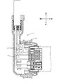
- an electric wire with a shorter distance inside the cover than the reference electric wire is guided by the guide portion into the extra length accommodation space which is originally a dead space, and the extra length of the electric wire is put into the extra length accommodation space. Can be routed. Thereby, it is possible to prevent the electric wires from getting entangled in the electric wire cover and prevent the workability of assembling the electric wire cover from being reduced.
- the extra length accommodating space in the wire cover is provided on a side opposite to the wire lead-out position with respect to the guide portion, and the guide portion is inclined in a direction different from the wire lead-out position. It is good also as a structure which has the inclined part which does.
- the plurality of electric wires are covered with an outer covering that collectively covers the plurality of electric wires, and a water stopping member that stops water between the plurality of electric wires and the outer covering at an end of the outer covering. It may be configured to be pulled out from the wire cover.
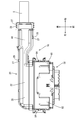
- the outer housing 60 is formed in a tubular shape penetrating in the front-rear direction, and the inner housing 51 can be fitted into the outer housing 60 from behind.
- the wire cover 20 has an elongated shape longer in the left-right direction than the housing 50.
- the electric wire cover 20 is a cover main body 22 having an electric wire introduction portion 21 in which a portion on the left side from a substantially central portion in the left and right direction is opened forward, and an electric wire on the right side of the cover main body 22 extends rightward.
- the deriving unit 40 is provided.
- the wire cover 20 is arranged at a position slightly behind the housing 50, and a joint cover 80 attached to a rear portion of the housing 50 and an outer periphery of a front end of the wire cover 20. To be fixed together.
- the upper joint cover 82 and the lower joint cover 81 can be locked in the front-rear direction with respect to the rear part of the housing 50 and the front end of the wire cover 20.
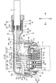
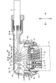
- a locking portion 36 is provided which protrudes from the bottom wall 35A of the electric wire routing portion 35 toward the inside of the electric wire routing portion 35.
- the locking portion 36 has an elongated round pin shape, is located slightly to the left of a substantially central portion in the left-right direction of the wire routing portion 35, and is disposed behind the right-side large-diameter wire routing path 32L. .
- two large-diameter electric wires WL and three small-diameter electric wires WS introduced from the guide unit 30 are introduced into the electric wire routing unit 35, and the two large-diameter electric wires WL are connected to the guide unit. After being introduced from 30, it is accommodated in the electric wire routing unit 35 in a state where it is bent substantially rightward to the right and extends almost linearly to the electric wire outlet 40.
- the technology disclosed in the present specification is not limited to the embodiments described above and illustrated in the drawings, and includes, for example, the following various aspects.
- the plurality of electric wires W are configured by the large-diameter electric wire WL and the small-diameter electric wire WS.
- the present invention is not limited to this, and the plurality of electric wires may be constituted by only large-diameter electric wires or only small-diameter electric wires, or may be constituted by electric wires having three or more types of wire diameters.
Landscapes
- Details Of Connecting Devices For Male And Female Coupling (AREA)
- Connector Housings Or Holding Contact Members (AREA)
Priority Applications (2)
| Application Number | Priority Date | Filing Date | Title |
|---|---|---|---|
| CN201980051329.1A CN112703641B (zh) | 2018-08-21 | 2019-08-01 | 电线盖及带电线盖连接器 |
| US17/268,514 US11329422B2 (en) | 2018-08-21 | 2019-08-01 | Wire cover and connector with wire cover |
Applications Claiming Priority (2)
| Application Number | Priority Date | Filing Date | Title |
|---|---|---|---|
| JP2018154454A JP6984564B2 (ja) | 2018-08-21 | 2018-08-21 | 電線カバーおよび電線カバー付きコネクタ |
| JP2018-154454 | 2018-08-21 |
Publications (1)
| Publication Number | Publication Date |
|---|---|
| WO2020039877A1 true WO2020039877A1 (ja) | 2020-02-27 |
Family
ID=69593009
Family Applications (1)
| Application Number | Title | Priority Date | Filing Date |
|---|---|---|---|
| PCT/JP2019/030176 Ceased WO2020039877A1 (ja) | 2018-08-21 | 2019-08-01 | 電線カバーおよび電線カバー付きコネクタ |
Country Status (4)
| Country | Link |
|---|---|
| US (1) | US11329422B2 (enExample) |
| JP (1) | JP6984564B2 (enExample) |
| CN (1) | CN112703641B (enExample) |
| WO (1) | WO2020039877A1 (enExample) |
Families Citing this family (3)
| Publication number | Priority date | Publication date | Assignee | Title |
|---|---|---|---|---|
| JP2022124641A (ja) * | 2021-02-16 | 2022-08-26 | 住友電装株式会社 | コネクタ |
| JP7694272B2 (ja) * | 2021-09-07 | 2025-06-18 | 株式会社プロテリアル | ワイヤハーネス及びケーブルの防水構造 |
| JP7630772B2 (ja) * | 2021-11-24 | 2025-02-18 | 株式会社オートネットワーク技術研究所 | コネクタ |
Citations (8)
| Publication number | Priority date | Publication date | Assignee | Title |
|---|---|---|---|---|
| JPH09261817A (ja) * | 1996-03-15 | 1997-10-03 | Molex Inc | 通信ケーブル配線トレー |
| US20010023146A1 (en) * | 2000-01-31 | 2001-09-20 | Framatome Connectors International | Cable connector |
| JP2001326020A (ja) * | 2000-05-15 | 2001-11-22 | Mitsubishi Electric Corp | 電気接続装置 |
| JP2003032866A (ja) * | 2001-07-12 | 2003-01-31 | Yazaki Corp | フラットワイヤハーネスおよびその余長吸収装置 |
| JP2004319417A (ja) * | 2003-04-21 | 2004-11-11 | Molex Inc | コンセント装置 |
| JP2013097898A (ja) * | 2011-10-28 | 2013-05-20 | Sumitomo Wiring Syst Ltd | シール部材 |
| US20150200496A1 (en) * | 2014-01-16 | 2015-07-16 | Tyco Electronics Corporation | Cable header connector |
| JP2016076295A (ja) * | 2014-10-02 | 2016-05-12 | 矢崎総業株式会社 | 電線係止装置 |
Family Cites Families (4)
| Publication number | Priority date | Publication date | Assignee | Title |
|---|---|---|---|---|
| JP2013122900A (ja) * | 2011-11-09 | 2013-06-20 | Sumitomo Wiring Syst Ltd | コネクタ |
| JP5778574B2 (ja) | 2011-12-27 | 2015-09-16 | 矢崎総業株式会社 | 電線カバー付きコネクタ |
| JP5667685B1 (ja) * | 2013-11-11 | 2015-02-12 | 日本航空電子工業株式会社 | コネクタ |
| JP2017010666A (ja) * | 2015-06-18 | 2017-01-12 | 住友電気工業株式会社 | 配線部材 |
-
2018
- 2018-08-21 JP JP2018154454A patent/JP6984564B2/ja active Active
-
2019
- 2019-08-01 CN CN201980051329.1A patent/CN112703641B/zh active Active
- 2019-08-01 WO PCT/JP2019/030176 patent/WO2020039877A1/ja not_active Ceased
- 2019-08-01 US US17/268,514 patent/US11329422B2/en active Active
Patent Citations (8)
| Publication number | Priority date | Publication date | Assignee | Title |
|---|---|---|---|---|
| JPH09261817A (ja) * | 1996-03-15 | 1997-10-03 | Molex Inc | 通信ケーブル配線トレー |
| US20010023146A1 (en) * | 2000-01-31 | 2001-09-20 | Framatome Connectors International | Cable connector |
| JP2001326020A (ja) * | 2000-05-15 | 2001-11-22 | Mitsubishi Electric Corp | 電気接続装置 |
| JP2003032866A (ja) * | 2001-07-12 | 2003-01-31 | Yazaki Corp | フラットワイヤハーネスおよびその余長吸収装置 |
| JP2004319417A (ja) * | 2003-04-21 | 2004-11-11 | Molex Inc | コンセント装置 |
| JP2013097898A (ja) * | 2011-10-28 | 2013-05-20 | Sumitomo Wiring Syst Ltd | シール部材 |
| US20150200496A1 (en) * | 2014-01-16 | 2015-07-16 | Tyco Electronics Corporation | Cable header connector |
| JP2016076295A (ja) * | 2014-10-02 | 2016-05-12 | 矢崎総業株式会社 | 電線係止装置 |
Also Published As
| Publication number | Publication date |
|---|---|
| CN112703641A (zh) | 2021-04-23 |
| JP2020030907A (ja) | 2020-02-27 |
| CN112703641B (zh) | 2022-06-28 |
| JP6984564B2 (ja) | 2021-12-22 |
| US20210265774A1 (en) | 2021-08-26 |
| US11329422B2 (en) | 2022-05-10 |
Similar Documents
| Publication | Publication Date | Title |
|---|---|---|
| US6485194B1 (en) | Optical connector | |
| US8304653B2 (en) | Protector for wire harness and method for fixing protector to wire harness | |
| WO2020039877A1 (ja) | 電線カバーおよび電線カバー付きコネクタ | |
| CN109314374B (zh) | 保护器以及线束 | |
| US20120073852A1 (en) | Electric junction box | |
| US20200295553A1 (en) | Electric connection box | |
| US20150035396A1 (en) | Motor provided with terminal block | |
| CN107054238A (zh) | 外部部件、外部部件制造方法及线束 | |
| JP6146618B2 (ja) | コネクタ | |
| JP6834645B2 (ja) | 防水コネクタ | |
| US20210399499A1 (en) | Terminal module and connector | |
| JP2020194635A (ja) | コネクタ及びワイヤーハーネス | |
| US20180351302A1 (en) | Connector housing | |
| JP6319752B2 (ja) | ワイヤハーネス | |
| JP6570897B2 (ja) | 電線経路規制用カバー | |
| JP7206906B2 (ja) | 端子モジュールおよびコネクタ | |
| US10030794B2 (en) | Corrugated tube and wire harness | |
| US20100178785A1 (en) | Wire connection unit | |
| JP3998550B2 (ja) | 電線案内用プロテクタ及びこのプロテクタに用いられる方向規制プロテクタ | |
| WO2022044663A1 (ja) | 成形コネクタ | |
| JP4796178B2 (ja) | 光モジュールガイド及びクロージャ | |
| JP2017163664A (ja) | 電線のプロテクタ保護構造 | |
| KR20130040335A (ko) | 멀티 플로어 박스 | |
| US20240282481A1 (en) | Wire harness | |
| JP5394696B2 (ja) | コネクタ |
Legal Events
| Date | Code | Title | Description |
|---|---|---|---|
| 121 | Ep: the epo has been informed by wipo that ep was designated in this application |
Ref document number: 19851502 Country of ref document: EP Kind code of ref document: A1 |
|
| DPE1 | Request for preliminary examination filed after expiration of 19th month from priority date (pct application filed from 20040101) | ||
| NENP | Non-entry into the national phase |
Ref country code: DE |
|
| 122 | Ep: pct application non-entry in european phase |
Ref document number: 19851502 Country of ref document: EP Kind code of ref document: A1 |