WO2020039876A1 - 多芯ケーブルの止水構造 - Google Patents
多芯ケーブルの止水構造 Download PDFInfo
- Publication number
- WO2020039876A1 WO2020039876A1 PCT/JP2019/030175 JP2019030175W WO2020039876A1 WO 2020039876 A1 WO2020039876 A1 WO 2020039876A1 JP 2019030175 W JP2019030175 W JP 2019030175W WO 2020039876 A1 WO2020039876 A1 WO 2020039876A1
- Authority
- WO
- WIPO (PCT)
- Prior art keywords
- sheath
- heat
- covering portion
- stopper
- core cable
- Prior art date
- Legal status (The legal status is an assumption and is not a legal conclusion. Google has not performed a legal analysis and makes no representation as to the accuracy of the status listed.)
- Ceased
Links
Images





Classifications
-
- H—ELECTRICITY
- H02—GENERATION; CONVERSION OR DISTRIBUTION OF ELECTRIC POWER
- H02G—INSTALLATION OF ELECTRIC CABLES OR LINES, OR OF COMBINED OPTICAL AND ELECTRIC CABLES OR LINES
- H02G3/00—Installations of electric cables or lines or protective tubing therefor in or on buildings, equivalent structures or vehicles
- H02G3/02—Details
- H02G3/04—Protective tubing or conduits, e.g. cable ladders or cable troughs
- H02G3/0462—Tubings, i.e. having a closed section
-
- H—ELECTRICITY
- H01—ELECTRIC ELEMENTS
- H01B—CABLES; CONDUCTORS; INSULATORS; SELECTION OF MATERIALS FOR THEIR CONDUCTIVE, INSULATING OR DIELECTRIC PROPERTIES
- H01B7/00—Insulated conductors or cables characterised by their form
- H01B7/0009—Details relating to the conductive cores
-
- H—ELECTRICITY
- H01—ELECTRIC ELEMENTS
- H01B—CABLES; CONDUCTORS; INSULATORS; SELECTION OF MATERIALS FOR THEIR CONDUCTIVE, INSULATING OR DIELECTRIC PROPERTIES
- H01B7/00—Insulated conductors or cables characterised by their form
- H01B7/17—Protection against damage caused by external factors, e.g. sheaths or armouring
- H01B7/28—Protection against damage caused by moisture, corrosion, chemical attack or weather
- H01B7/282—Preventing penetration of fluid, e.g. water or humidity, into conductor or cable
-
- H—ELECTRICITY
- H02—GENERATION; CONVERSION OR DISTRIBUTION OF ELECTRIC POWER
- H02G—INSTALLATION OF ELECTRIC CABLES OR LINES, OR OF COMBINED OPTICAL AND ELECTRIC CABLES OR LINES
- H02G1/00—Methods or apparatus specially adapted for installing, maintaining, repairing or dismantling electric cables or lines
- H02G1/14—Methods or apparatus specially adapted for installing, maintaining, repairing or dismantling electric cables or lines for joining or terminating cables
Definitions
- the technology disclosed in this specification relates to a waterproof structure for a multi-core cable including a plurality of electric wires.
- Patent Document 1 As a waterproof structure of a multi-core cable in which a plurality of electric wires are surrounded by a sheath, a structure described in Patent Document 1 is known. A plurality of electric wires are led out from the end of the multi-core cable. A heat-shrinkable tube is placed over a region from the outer periphery of the plurality of electric wires to the outer periphery of the sheath. The hot melt block is held between the heat-shrinkable tube and the plurality of electric wires in a state of being solidified after melting.
- the heat-shrinkable tube shrinks to a predetermined shape when heated. For this reason, when the heat-shrinkable tube is insufficiently heated, the energized multi-core cable generates heat and the heat-shrinkable tube is reheated. As a result, the heat collection tube may be further shrunk. Then, there is a concern that the heat-shrinkable tube may move from the end of the sheath to the outer peripheral portions of the plurality of electric wires having smaller outer diameter dimensions as a whole. When the heat-shrinkable tube comes off from the sheath in this manner, the solidified hot melt block is exposed after melting, and the water stopping performance of the multi-core cable may be reduced.
- a plurality of electric wires are surrounded by a sheath, a multi-core cable from which the plurality of electric wires are led out from the end of the sheath, and a sheath covering portion that covers the sheath.
- a heat-shrinkable tube having an electric wire covering portion connected to the sheath covering portion and covering the plurality of electric wires derived from the end portion of the sheath, and the electric wire covering portion, and the plurality of electric wires.
- a water blocking portion arranged in the gap and stopping water between the wire covering portion and the plurality of wires, and holding the heat-shrinkable tube therein, and the heat-shrinkable tube on the wire-covering portion side of the heat-shrinkable tube.
- a protector having a stopper located in the vicinity of the end, wherein the heat-shrinkable tube has a length dimension L1 of the sheath coating portion that is equal to a distance L2 between the end portion and the stopper on the wire coating portion side. It is also set large.
- the heat-shrinkable tube is supported by the stopper even when the heat-shrinkable tube is shrunk by receiving heat, so that the heat-shrinkable tube moves in a direction to come off the sheath.
- the heat-shrinkable tube moves by the distance L2 between the end of the heat-shrinkable tube and the stopper before the end of the heat-shrinkable tube on the side of the wire-covered portion contacts the stopper. Since the length L1 of the sheath covering portion is set to be larger than the interval L2, at least a part of the sheath covering portion in a state where the end on the wire covering portion side of the heat-shrinkable tube is supported by the stopper. Are kept covered with the sheath.
- the heat-shrinkable tube is prevented from coming off from the end of the sheath, so that the water-stop portion disposed between the wire covering portion and the plurality of wires is prevented from being exposed. As a result, it is possible to suppress a decrease in the water stopping performance of the multi-core cable.
- the stopper is located forward of the end of the heat-shrinkable tube on the wire covering portion side in a direction from the sheath covering portion to the wire covering portion.
- the tube when the heat-shrinkable tube attempts to move in a direction away from the sheath, that is, in a direction from the sheath covering portion to the electric wire covering portion, the tube is reliably prevented from coming off.
- the tube is reliably prevented from coming off.
- the protector has a sheath holding portion for holding the sheath.
- the sheath and the protector are positioned relative to each other by the sheath holding portion of the protector holding the sheath.
- the relative positioning of the sheath and the stopper of the protector is performed, so that in a state where the end of the heat-shrinkable tube on the wire covering portion side is supported by the stopper, the sheath holding portion is attached to the outer periphery of the sheath.
- the stopper can be arranged so as to securely cover. As a result, a decrease in the water stopping performance of the multi-core cable can be reliably suppressed.
- the plurality of electric wires led out of the sheath are surrounded by an exterior member different from the sheath, and the protector has an exterior member holding portion that holds the exterior member.
- a heat-shrinkable tube, a plurality of wires exposed from the heat-shrinkable tube in a region between the heat-shrinkable tube and the outer member Can be covered with a protector.
- the stopper is provided at a position corresponding to a diameter portion of the end of the wire covering portion.
- the stopper can come into contact with the region corresponding to the diameter portion of the end of the wire covering portion, so that the heat-shrinkable tube can be reliably prevented from coming off.
- the stopper it is possible to surely prevent the water stopping performance of the multi-core cable from being reduced.
- the protector has a wire guide portion that contacts at least one of the plurality of wires and guides the at least one wire.
- the electric wires arranged inside the protector are guided by the electric wire guides, so that the arrangement in the protector due to the vibration is suppressed. Accordingly, the relative positions of the plurality of electric wires and the water stopping portion are suppressed from being shifted, so that the water stopping performance of the multi-core cable can be further suppressed from being reduced.
- the wire guide portion and the stopper are integrally formed.
- the structure of the protector can be simplified as compared with the case where the wire guide portion and the stopper are separate members.
- the water stop portion contains a hot melt resin.
- the heating step for melting the hot melt resin and the heating step for shrinking the heat-shrinkable tube can be performed in the same step. Efficiency can be improved.
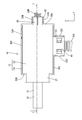
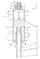
- FIG. 2 is a cross-sectional view taken along the line II in FIG. 2, showing a waterproof structure of the multi-core cable according to the first embodiment.
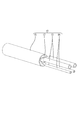
- Bottom view showing waterproof structure of multi-core cable
- the perspective view which shows the multi-core cable in the state where the front end part of the sheath was peeled.
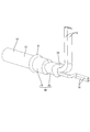
- a perspective view showing a process of attaching a waterproof block and a heat-shrinkable tube to the peeled multicore cable.
- Perspective view showing a state in which a waterproof block and a heat-shrinkable tube are attached to a peeled multicore cable.
- Perspective view showing a multi-core cable after heating A perspective view showing a state where a multi-core cable is arranged in a lower case.
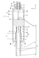
- Sectional drawing which shows the water-stop structure of a multi-core cable in the state where the heat-shrinkable tube moved forward.
- Perspective view showing an upper case and a multi-core cable according to a second embodiment.
- Sectional drawing which shows the water stop structure of the multicore cable which concerns on Embodiment 3.
- the waterproof structure 11 of the multi-core cable 10 according to the present embodiment includes the multi-core cable 10 and a protector 12.
- the water stopping structure 11 of the multi-core cable 10 according to the present embodiment is disposed in a portion of the vehicle (not shown), such as a tire house or an engine room, where water may be applied to the multi-core cable 10.
- the Z direction is upward
- the Y direction is forward
- the X direction is left.
- symbol is attached
- the multi-core cable 10 includes a plurality (two in the present embodiment) of power lines 13 (an example of an electric wire) and a plurality (two in the present embodiment) of a signal line 14 (an example of an electric wire). And the outer circumferences of the power line 13 and the signal line 14 are collectively surrounded by a sheath 15 made of insulating synthetic resin.
- the sheath 15 has a hollow cylindrical shape.
- a power line 13 and a signal line 14 are led forward from a front end 16 of the sheath 15.
- the cross-sectional shapes of the power line 13 and the signal line 14 are substantially circular.
- the diameter of the power line 13 is set to be larger than the diameter of the signal line 14.
- a filler 17 is disposed between the inner surface of the sheath 15 and the power line 13 and the signal line 14.
- any material such as a synthetic resin, a synthetic fiber, and a natural fiber can be appropriately selected.
- Heat shrink tube 18 As shown in FIG. 1, a region near the front end 16 of the sheath 15 and a region near the front end 16 of the sheath 15 in the power line 13 and the signal line 14 led forward from the front end 16 of the sheath 15. Is covered with a heat-shrinkable tube 18.
- the heat-shrinkable tube 18 is made of a synthetic resin and has a hollow cylindrical shape. The heat-shrinkable tube 18 contracts when heated to a predetermined temperature.
- an arbitrary synthetic resin such as a crosslinked polyolefin resin can be appropriately selected.
- the heat-shrinkable tube 18 before being heated to a predetermined temperature, has a hollow cylindrical shape.
- An adhesive is applied to the inner surface of the heat-shrinkable tube 18 according to the present embodiment. The adhesive melts when heated to a predetermined temperature, and solidifies at room temperature. The adhesive may not be applied to the inner surface of the heat-shrinkable tube 18.
- FIG. 6 shows the shape of the heat-shrinkable tube 18 after heat treatment to a predetermined temperature.
- the heat-shrinkable tube 18 is provided with a sheath covering portion 19 covering the outer surface of the sheath 15, and an electric wire connected to the front of the sheath covering portion 19 and covering the power line 13 and the signal line 14 led forward from the front end 16 of the sheath 15. And a covering portion 20.
- the rear part of the heat-shrinkable tube 18 is a sheath coating part 19
- the front part of the heat-shrinkable tube 18 is a wire coating part 20.
- the outer diameter of the sheath coating 19 is larger than the outer diameter of the electric wire coating 20.
- a rear leakage portion 21 is formed at the rear end of the sheath covering portion 19 by solidifying after the molten adhesive leaks backward from the rear end portion of the sheath covering portion 19. Have been.
- the rear leak part 21 is formed so as to leak backward from the rear end of the sheath covering part 19 and to cover the rear end of the sheath covering part 19 from outside in the radial direction of the sheath covering part 19. .
- the rear leak portion 21 prevents water from entering from a gap between the rear end of the sheath covering portion 19 and the sheath 15.
- an adhesive that has been melted and solidified is located between the inner surface of the sheath covering portion 19 and the outer surface of the sheath 15, and the adhesive covers the sheath covering portion 19 and the sheath. 15 is stopped.
- a water stop section 22 is arranged between the electric wire covering section 20 and the power line 13 and the signal line 14.
- the water stopping portion 22 is disposed so as to fill a gap between the inner surface of the electric wire covering portion 20 and the outer surface of the power line 13 and the outer surface of the signal line 14, so that the electric wire covering portion 20, the power line 13, and the signal line 14 are provided. It is designed to stop the water between.
- the water blocking portion 22 is formed by mixing and solidifying the adhesive applied to the inner surface of the wire covering portion 20 and a water blocking block 23 described later after melting.
- the synthetic resin forming the water blocking block 23 and the synthetic resin forming the adhesive may be the same or different.
- the molten adhesive and the melted water blocking block 23 are mixed and leaked forward from the front end portion 16 of the wire covering portion 20 and then solidified, so that the front leakage occurs.
- a part 24 is formed.
- the front leakage portion 24 is formed so as to leak forward from the front end portion 16 of the electric wire covering portion 20 and to cover the front end portion 16 of the electric wire covering portion 20 from outside in the radial direction of the electric wire covering portion 20.
- the front leakage portion 24 prevents water from entering through a gap between the front end 16 of the electric wire covering portion 20 and the sheath 15.
- the protector 12 As shown in FIG. 1, at least the heat-shrinkable tube 18 is held inside a box-shaped protector 12 made of synthetic resin.
- the protector 12 includes a lower case 25 that opens upward and is located below, and an upper case 26 that is integrally assembled with the lower case 25 with the opening of the lower case 25 closed from above.
- the lower case 25 includes a substantially rectangular bottom wall 27 extending in the front-rear direction and four side walls 28A, 28B, 28C, 28D extending upward from side edges of the bottom wall 27.
- the upper case 26 includes a substantially rectangular upper wall 29 that is elongated in the front-rear direction (see FIG. 1), and side walls 30A, 30B, 30C, and 30D that extend downward from side edges of the upper wall 29 (see FIG. 2).
- the shape of the upper wall 29 of the upper case 26 corresponds to the shape of the bottom wall 27 of the lower case 25.
- corrugated tubes 35A and 35B described later are omitted.
- a lower sheath holding portion 33 is formed on the side wall 28 ⁇ / b> B located on the rear side of the lower case 25.
- the lower sheath holding portion 33 is recessed in a shape following the outer shape of the sheath 15.
- the lower sheath holding portion 33 has a substantially semicircular concave shape.
- the upper sheath holding portion 34 has a substantially semicircular concave shape.
- the sheath 15 of the multi-core cable 10 is held by being vertically sandwiched between the lower sheath holding portion 33 and the upper sheath holding portion 34. . Specifically, the lower sheath holding portion 33 and the upper sheath holding portion 34 are located at a position behind the rear end of the sheath covering portion 19 that covers the outer periphery of the sheath 15 and the rear leakage portion. The sheath 15 is held at a position behind the sheath 21. Thereby, the sheath 15 and the protector 12 do not relatively move.
- the power line 13 led forward from the front end portion 16 of the electric wire covering portion 20 is bent leftward and routed.
- the signal line 14 led forward from the front end 16 of the wire covering portion 20 extends forward and is routed.
- the power line 13 and the signal line 14 are branched out after being led forward from the front end 16 of the electric wire covering portion 20, respectively.
- the power line 13 branched from the front end 16 of the sheath 15 is surrounded by a corrugated tube 35A (an example of an exterior member), and the signal line 14 branched from the front end 16 of the sheath 15 is surrounded by a corrugated tube 35B (an example of an exterior member).
- a corrugated tube 35A an example of an exterior member
- the signal line 14 branched from the front end 16 of the sheath 15 is surrounded by a corrugated tube 35B (an example of an exterior member).
- the corrugated tubes 35A and 35B are made of insulating synthetic resin and have a bellows-like hollow cylindrical shape.
- a lower corrugated tube holding portion 36 (an example of an exterior member holding portion) that protrudes forward is formed on the front side wall 28A of the lower case 25.
- the lower corrugated tube holding portion 36 is formed in a groove shape having a substantially U-shaped cross section and opening upward.
- the lower corrugated tube holding portion 36 is formed with a plurality of lower holding ribs 37 that protrude upward and are arranged at intervals in the front-rear direction.
- An upper corrugated tube holding portion 38 (an example of an exterior member holding portion) that protrudes forward is formed on the front side wall 30A of the upper case 26.
- the upper corrugated tube holding portion 38 is formed in a groove shape having a substantially U-shaped cross section and opening downward.
- the upper corrugated tube holding portion 38 is formed with a plurality of upper holding ribs 39 that protrude downward and are arranged at intervals in the front-rear direction.
- the corrugated tube 35B surrounding the signal line 14 is connected to the lower corrugated tube holding portion 36 and the upper corrugated tube holding portion 38. It is held by being sandwiched from above and below. More specifically, the lower corrugated tube holding portion 36 is fitted into the bellows shape of the corrugated tube 35B from below, and the upper retaining rib 39 of the upper corrugated tube holding portion 38 is fitted from above. The tube 35B is held by the protector 12.
- a lower corrugated tube holding portion 40 (an example of an exterior member holding portion) that holds a corrugated tube 35A surrounding the power line 13 is provided on the left side wall 28C of the lower case 25.
- An upper corrugated tube holding portion 41 (an example of an exterior member holding portion) that holds a corrugated tube 35A that surrounds the power line 13 is provided on the left side wall 30C of the upper case 26.
- a lock portion 31A protruding outward is formed on the outer surface of the side wall 28D located on the right side of the lower case 25.
- a lock receiving portion 32A elastically engaged with the lock portion 31A is formed at a position corresponding to the lock portion 31A on the side wall 30D of the upper case 26.
- a lock portion 31B protruding outward is formed on the outer surface of the lower corrugated tube holding portion 36.
- the upper corrugated tube holding portion 38 has a lock receiving portion 32B which is elastically engaged with the lock portion 31B at a position corresponding to the lock portion 31B.
- a lock portion 31C protruding outward is formed on the outer surface of the lower corrugated tube holding portion 40.
- the upper corrugated tube holding portion 41 is formed with a lock receiving portion 32C that elastically engages with the lock portion 31C at a position corresponding to the lock portion 31C.
- the lock portion 31A and the lock receiving portion 32A elastically engage with each other, the lock portion 31B and the lock receiving portion 32B elastically engage with each other, and the lock portion 31C and the lock receiving portion 32C elastically engage with each other.
- the lower case 25 and the upper case 26 are integrally assembled.
- Stopper 42 As shown in FIG. 1, a stopper 42 protruding upward is formed on the bottom wall 27 of the lower case 25.
- the stopper 42 is provided in the vicinity of the front end 16 of the wire covering portion 20 in a state where the lower case 25 and the upper case 26 are integrally assembled and the sheath 15 is held by the lower sheath holding portion 33 and the upper sheath holding portion 34. Is provided.
- the stopper 42 is located at a position forward of the front end 16 of the wire covering portion 20 in the direction from the sheath covering portion 19 toward the wire covering portion 20 and forward from the front leakage portion 24. It is provided at a separated position.
- the stopper 42 is provided at a position corresponding to the diameter of the front end 16 of the wire covering portion 20 in the sheath 15 in the vertical direction.
- the vertical dimension of the stopper 42 is set to be larger than the diameter dimension of the electric wire covering 20.
- the upper end of the stopper 42 is in contact with the upper wall 29 of the upper case 26 from below.
- the stopper 42 has a generally tear-like shape in which a front portion is formed wider than a rear portion when viewed from above.
- the left side surface of the stopper 42 is formed in a concave shape, and serves as a power line guide 43 (an example of an electric wire guide) that guides the power line 13 to the left by contacting the power line 13.
- the right side surface of the stopper 42 is formed in a substantially linear shape, and serves as a signal line guide portion 44 (an example of an electric wire guide portion) that contacts the signal line 14 and guides the signal line 14 forward.
- the stopper 42, the power line guide 43, and the signal line guide 44 are integrally formed.
- the length L1 of the sheath covering portion 19 is set to be larger than the distance L2 between the front end 16 of the wire covering portion 20 and the stopper 42.
- the power line 13 and the signal line 14 are exposed by peeling the sheath 15 of the multi-core cable 10 by a predetermined length.
- the water blocking block 23 is attached to the power line 13 and the signal line 14 exposed from the sheath 15.
- the water blocking block 23 is composed of four locking walls 45 formed in a radial cross section (in this embodiment, a cross-shaped cross section branched at 90-degree central angles).
- the power line 13 and the signal line 14 are arranged in four spaces partitioned by the four locking walls 45, respectively. Thereby, the locking wall 45 is arranged between each power line 13 and each signal line 14.
- Heat treatment is performed by a known heating method.
- the water blocking block 23 is heated to a predetermined temperature or higher, so that the melted water stopping block 23 is filled between the power line 13 and the signal line 14.
- the adhesive applied to the inner surface of the heat-shrinkable tube 18 is melted and filled between the heat-shrinkable tube 18 and the sheath 15, and at the same time, the heat-shrinkable tube 18 is Will be filled.
- the molten water blocking block 23 and the molten adhesive are mixed.
- the heat-shrinkable tube 18 shrinks when the heat-shrinkable tube 18 is heated to a predetermined temperature or higher.
- the molten adhesive leaks from the rear end portion of the sheath covering portion 19 and solidifies to form the rear leakage portion 21.
- a mixture of the molten adhesive and the molten water blocking block 23 leaks and solidifies from the front end 16 of the electric wire covering portion 20 to form the front leakage portion 24 (see FIG. 6).
- the multi-core cable 10 to which the corrugated tubes 35A and 35B are attached is arranged in the lower case 25.
- the sheath 15 is placed on the lower sheath holding portion 33 of the lower case 25.
- the corrugated tube 35B is placed on the lower corrugated tube holder 36, and the corrugated tube 35A is placed on the lower corrugated tube holder 40.
- the length L1 of the sheath covering portion 19 is set to be larger than the distance L2 between the front end 16 of the wire covering portion 20 and the stopper 42.
- the corrugated tubes 35A and 35B are omitted.
- the upper case 26 is assembled to the lower case 25 from above, and the lock portions 31A, 31B, 31C and the lock receiving portions 32A, 32B, 32C are elastically engaged with each other.
- the sheath 15 is held by the protector 12 by being sandwiched between the lower sheath holding portion 33 and the upper sheath holding portion 34.
- the corrugated tube 35A is held by the protector 12 by being sandwiched between the lower corrugated tube holding portion 40 and the upper corrugated tube holding portion 41, and the corrugated tube 35B is held by the lower corrugated tube holding portion 36 and the upper corrugated tube. It is held by the protector 12 by being sandwiched by the holding portion 38.
- the waterproof structure 11 of the multi-core cable 10 is completed (see FIG. 1).
- the waterproof structure 11 of the multi-core cable 10 has a multi-core structure in which the power line 13 and the signal line 14 are surrounded by the sheath 15 and the power line 13 and the signal line 14 are led out from the end of the sheath 15.
- a water stopping portion 22 arranged in a gap between the shrink tube 18, the electric wire covering portion 20, the power line 13 and the signal line 14, and stopping water between the electric wire covering portion 20 and the power line 13 and the signal line 14;
- a protector 12 having a stopper 42 located near the front end of the heat-shrinkable tube 18 while holding the heat-shrinkable tube 18 therein.
- the length L1 of over scan covering portion 19 is set larger than the distance L2 between the front end portion 16 and the stopper 42 of the wire cover 20.
- the length dimension L1 of the sheath covering portion 19 is set to be larger than the distance L2 between the front end 16 of the wire covering portion 20 and the stopper 42. Have been. Thereafter, when a current is applied to the multi-core cable 10 to generate heat, the heat-shrinkable tube 18 may further contract. At a temperature at which the heat-shrinkable tube 18 shrinks, the water stop portion 22 may also be softened. Then, the heat-shrinkable tube 18 slides on the surface of the softened water blocking portion 22, and moves from the sheath 15 having a relatively large diameter to a region where the power line 13 and the signal line 14 having a smaller diameter as a whole are exposed. Moving.
- the heat-shrinkable tube 18 is contracted by receiving heat, the heat-shrinkable tube 18 is moved in the direction (in the present embodiment, forward) coming off the sheath 15, the heat-shrinkage is performed by the stopper 42.
- the tube 18 is supported (see FIG. 8).
- the sheath covering portion of the heat-shrinkable tube 18 is supported with the front end portion 16 of the wire covering portion 20 supported by the stopper 42. At least a part of 19 is kept in a state where sheath 15 is covered. As a result, the heat-shrinkable tube 18 is prevented from coming off from the end of the sheath 15, so that the water blocking portion 22 disposed between the electric wire covering portion 20 and the power line 13 and the signal line 14 is exposed. Is suppressed. As a result, it is possible to suppress a decrease in the water stopping performance of the multi-core cable 10.
- the front leakage portion 24 since the front leakage portion 24 is formed at the front end 16 of the wire covering portion 20, the front leakage portion 24 comes into contact with the stopper 42 from behind. Thus, the stopper 42 prevents the heat-shrinkable tube 18 from moving forward through the front leakage part 24.
- the stopper 42 is located forward of the front end portion 16 of the wire covering portion 20 in the heat-shrinkable tube 18 in the direction from the sheath covering portion 19 toward the wire covering portion 20. .
- the stopper 42 is surely prevented from coming off. Thereby, it is possible to reliably prevent the water stopping performance of the multi-core cable 10 from being reduced.
- the protector 12 has the sheath 15 holding unit that holds the sheath 15.
- the sheath 15 and the protector 12 are positioned relative to each other by the sheath 15 holding portion of the protector 12 holding the sheath 15.
- the relative positioning between the sheath 15 and the stopper 42 of the protector 12 is performed, so that the sheath 15 is supported in a state where the end of the heat-shrinkable tube 18 on the wire covering portion 20 side is supported by the stopper 42.
- the stopper 42 can be arranged so that the holding portion surely covers the outer periphery of the sheath 15. As a result, a decrease in the water stopping performance of the multi-core cable 10 can be reliably suppressed.
- the power line 13 derived from the sheath 15 is surrounded by the corrugated tube 35A, and the signal line 14 is surrounded by the corrugated tube 35B.
- the corrugated tube 35A and the corrugated tube 35B are members different from the sheath 15.
- the protector 12 has a lower corrugated tube holding portion 40 and an upper corrugated tube holding portion 41 that hold the corrugated tube 35A, and has a lower corrugated tube holding portion 36 and an upper corrugated tube holding portion 38 that hold the corrugated tube 35B.
- the protector 12 and the corrugated tubes 35A and 35B can be relatively positioned.
- the heat shrinkable tube 18, the power line 13 and the signal line 14, which are exposed from the ends of the corrugated tubes 35 ⁇ / b> A and 35 ⁇ / b> B can be reliably covered with the protector 12.
- the protector 12 can protect the heat-shrinkable tube 18, the power line 13 and the signal line 14 from collision of foreign matter, so that the water stop performance of the multi-core cable 10 is further suppressed from being reduced. Can be.
- the stopper 42 is provided at a position corresponding to the diameter of the front end 16 of the wire covering 20.
- the stopper 42 can come into contact with the area corresponding to the diameter of the front end portion 16 of the electric wire covering portion 20, so that the heat-shrinkable tube 18 can be reliably prevented from coming off. Thereby, it is possible to reliably prevent the water stopping performance of the multi-core cable 10 from being reduced.
- the protector 12 has the power line guide portion 43 that contacts the power line 13 and guides the power line 13 to the left, and the signal that contacts the signal line 14 and guides the signal line forward. It has a line guide section 44.
- the power line 13 and the signal line 14 disposed inside the protector 12 are guided by the power line guide 43 and the signal line guide 44, respectively, so that the arrangement in the protector 12 is caused by vibration. Deviation is suppressed. Accordingly, the relative position between the power line 13 and the signal line 14 and the water stopping portion 22 is suppressed from being shifted, so that the water stopping performance of the multi-core cable 10 can be further suppressed from being reduced.
- the power line guide 43 and the signal line guide 44 and the stopper 42 are integrally formed.
- the structure of the protector 12 can be simplified as compared with the case where the power line guide 43 and the signal line guide 44 and the stopper 42 are separate members.
- the water stopping portion 22 contains a hot melt resin.
- the heating step for melting the water blocking block 23 containing the hot melt resin and the heating step for shrinking the heat-shrinkable tube 18 can be performed in the same step.
- the efficiency of the water stopping operation of the core cable 10 can be improved.
- a stopper 52 extending downward is formed on the upper wall 51 of the upper case 50 according to the present embodiment.
- no stopper is formed on the bottom wall of the lower case (not shown).
- the front-side leakage portion 24 formed on the multi-core cable 10 is in contact with the stopper 42 from behind.
- the length dimension L1 of the sheath covering portion 19 is set to be larger than the distance L2 between the front end 16 of the wire covering portion 20 and the stopper 42.
- the stopper 42 securely contacts with the stopper 24. Thereby, it is possible to reliably prevent the water stopping performance of the multi-core cable 10 from being reduced.
- the front end portion 16 of the electric wire covering portion 20 may directly contact the stopper 42 from behind.
- the number of electric wires included in the multi-core cable 10 may be two, three, five or more.
- the diameter dimensions of the electric wires included in the multi-core cable 10 may all be the same.
- the water blocking portion 22 may be formed by solidifying the adhesive applied to the inner surface of the heat-shrinkable tube 18 after melting.
- the armor member for arming the plurality of electric wires derived from the sheath 15 is not limited to the corrugated tubes 35A and 35B, and any armor member can be appropriately selected.
- the stopper 42 may be configured to be in contact with a region of the wire covering portion 20 that is different from the diameter portion. Further, a configuration in which the wire covering portion 20 is supported by the plurality of stoppers 42 may be specified.
- the electric wire guide may be omitted. Further, the stopper and the wire guide may be separate members.
- the water stopping portion 22 may be a rubber stopper through which the power line 13 and the signal line 14 pass.
- a stopper which is a member separate from the protector 12, may be assembled to the protector 12.
- the shape of the stopper can be any shape such as a cylinder, a square pillar, a triangular pillar, or the like, if necessary.
- Multi-core cable 11 Water blocking structure 12: Protector 13: Power line (an example of electric wire) 14: Signal line (an example of electric wire) 15: sheath 16: front end 18: heat-shrinkable tube 19: sheath covering portion 20: electric wire covering portion 22: water blocking portion 33: lower sheath holding portion 34: upper sheath holding portion 35A, 35B: corrugated tube (of the exterior member) One case) 36, 40: Lower corrugated tube holding part (an example of the exterior member holding part) 38, 41: Upper corrugated tube holding part (an example of the exterior member holding part) 42, 52: Stopper 43: Power line guide (example of electric wire guide) 44: signal line guide (example of electric wire guide)
Landscapes
- Engineering & Computer Science (AREA)
- Architecture (AREA)
- Civil Engineering (AREA)
- Structural Engineering (AREA)
- Cable Accessories (AREA)
- Insulated Conductors (AREA)
- Processing Of Terminals (AREA)
- Details Of Indoor Wiring (AREA)
Priority Applications (2)
| Application Number | Priority Date | Filing Date | Title |
|---|---|---|---|
| US17/267,076 US11227704B2 (en) | 2018-08-21 | 2019-08-01 | Multicore cable waterproofing structure |
| CN201980051264.0A CN112514191B (zh) | 2018-08-21 | 2019-08-01 | 多芯电缆的止水结构 |
Applications Claiming Priority (2)
| Application Number | Priority Date | Filing Date | Title |
|---|---|---|---|
| JP2018154453A JP6947138B2 (ja) | 2018-08-21 | 2018-08-21 | 多芯ケーブルの止水構造 |
| JP2018-154453 | 2018-08-21 |
Publications (1)
| Publication Number | Publication Date |
|---|---|
| WO2020039876A1 true WO2020039876A1 (ja) | 2020-02-27 |
Family
ID=69593015
Family Applications (1)
| Application Number | Title | Priority Date | Filing Date |
|---|---|---|---|
| PCT/JP2019/030175 Ceased WO2020039876A1 (ja) | 2018-08-21 | 2019-08-01 | 多芯ケーブルの止水構造 |
Country Status (4)
| Country | Link |
|---|---|
| US (1) | US11227704B2 (cg-RX-API-DMAC7.html) |
| JP (1) | JP6947138B2 (cg-RX-API-DMAC7.html) |
| CN (1) | CN112514191B (cg-RX-API-DMAC7.html) |
| WO (1) | WO2020039876A1 (cg-RX-API-DMAC7.html) |
Families Citing this family (1)
| Publication number | Priority date | Publication date | Assignee | Title |
|---|---|---|---|---|
| TWI744995B (zh) * | 2020-07-22 | 2021-11-01 | 榮晶生物科技股份有限公司 | 電子裝置 |
Citations (3)
| Publication number | Priority date | Publication date | Assignee | Title |
|---|---|---|---|---|
| JP2017139151A (ja) * | 2016-02-04 | 2017-08-10 | 株式会社オートネットワーク技術研究所 | 熱収縮チューブ付電線 |
| JP2018125122A (ja) * | 2017-01-31 | 2018-08-09 | 日立金属株式会社 | ワイヤハーネス |
| JP2018125935A (ja) * | 2017-01-31 | 2018-08-09 | 日立金属株式会社 | ケーブルの止水構造、ワイヤハーネス、及びワイヤハーネスの製造方法 |
Family Cites Families (17)
| Publication number | Priority date | Publication date | Assignee | Title |
|---|---|---|---|---|
| US3585275A (en) * | 1970-02-19 | 1971-06-15 | George W Gillemot | Kit and method for encapsulating conductor splice connections |
| GB1604379A (en) * | 1977-11-08 | 1981-12-09 | Raychem Sa Nv | Heat shrinkable article |
| US4504699A (en) * | 1982-02-08 | 1985-03-12 | Raychem Pontoise S.A. | Sealable recoverable articles |
| JPH0799080A (ja) * | 1993-09-29 | 1995-04-11 | Sumitomo Wiring Syst Ltd | 電線相互の接続方法 |
| US6359226B1 (en) * | 1998-04-21 | 2002-03-19 | Tyco Electronics Corporation | Device and method for protecting and sealing exposed wires |
| JP4433953B2 (ja) * | 2004-09-09 | 2010-03-17 | 住友電装株式会社 | 端末スプライス部の防水処理方法および防水処理構造 |
| US20060180336A1 (en) * | 2005-02-15 | 2006-08-17 | King Lloyd H Jr | Twist-on wire connector with peelable covering |
| CN100392457C (zh) * | 2005-12-27 | 2008-06-04 | 江苏中天科技股份有限公司 | 海底光缆分支接头盒及其连接工艺 |
| KR100809010B1 (ko) * | 2006-08-11 | 2008-03-14 | 경신공업 주식회사 | 고전압 케이블 |
| JP2012182924A (ja) | 2011-03-02 | 2012-09-20 | Sumitomo Wiring Syst Ltd | 線間止水用のホットメルトブロックおよび該ホットメルトブロックを用いた多芯ケーブルの端末止水方法ならびに端末止水構造 |
| JP2013109847A (ja) * | 2011-11-17 | 2013-06-06 | Yazaki Corp | 芯線止水構造及び芯線止水方法 |
| DE112015003249T5 (de) * | 2014-07-15 | 2017-04-13 | Sumitomo Electric Fine Polymer, Inc. | Wärmeschrumpfbares Rohr, wärmeschrumpfbarer Deckel und Verfahren zur Erzeugung einer Wasserresistenz bei einem elektrischen Drahtbündel |
| JP6311938B2 (ja) * | 2015-03-02 | 2018-04-18 | 株式会社オートネットワーク技術研究所 | 多芯ケーブルのシール構造 |
| CN206790070U (zh) * | 2017-04-28 | 2017-12-22 | 厦门福莱德电气有限公司 | 一种用于电线的防水插件装置 |
| CN107104412A (zh) * | 2017-05-31 | 2017-08-29 | 倍仕得电气科技(杭州)股份有限公司 | 一种一体式电缆固定头及装夹方法 |
| JP7088696B2 (ja) * | 2018-03-12 | 2022-06-21 | 矢崎総業株式会社 | 電線接続構造及び電線接続構造の製造方法 |
| JP6992685B2 (ja) * | 2018-06-14 | 2022-01-13 | 株式会社オートネットワーク技術研究所 | 電線の芯線露出部の防水構造 |
-
2018
- 2018-08-21 JP JP2018154453A patent/JP6947138B2/ja active Active
-
2019
- 2019-08-01 US US17/267,076 patent/US11227704B2/en active Active
- 2019-08-01 CN CN201980051264.0A patent/CN112514191B/zh active Active
- 2019-08-01 WO PCT/JP2019/030175 patent/WO2020039876A1/ja not_active Ceased
Patent Citations (3)
| Publication number | Priority date | Publication date | Assignee | Title |
|---|---|---|---|---|
| JP2017139151A (ja) * | 2016-02-04 | 2017-08-10 | 株式会社オートネットワーク技術研究所 | 熱収縮チューブ付電線 |
| JP2018125122A (ja) * | 2017-01-31 | 2018-08-09 | 日立金属株式会社 | ワイヤハーネス |
| JP2018125935A (ja) * | 2017-01-31 | 2018-08-09 | 日立金属株式会社 | ケーブルの止水構造、ワイヤハーネス、及びワイヤハーネスの製造方法 |
Also Published As
| Publication number | Publication date |
|---|---|
| US20210313093A1 (en) | 2021-10-07 |
| CN112514191B (zh) | 2022-06-28 |
| US11227704B2 (en) | 2022-01-18 |
| CN112514191A (zh) | 2021-03-16 |
| JP2020031464A (ja) | 2020-02-27 |
| JP6947138B2 (ja) | 2021-10-13 |
Similar Documents
| Publication | Publication Date | Title |
|---|---|---|
| US10003141B2 (en) | Seal structure for multi-core cable | |
| US9972417B2 (en) | Electrically conducting path | |
| US11170913B2 (en) | Waterproofing structure and waterproofing method for shielded cable | |
| EP3763575B1 (en) | Wire harness, wire harness manufacturing method and wire harness manufacturing device | |
| US3209069A (en) | Joint enclosure for joined electric cables | |
| US7153146B2 (en) | Termination structure of cable with shield layer | |
| US11329422B2 (en) | Wire cover and connector with wire cover | |
| JP2019075882A (ja) | シールド電線の止水構造及び止水方法 | |
| JP2020031464A (ja) | 多芯ケーブルの止水構造 | |
| US12034285B2 (en) | Hot melt block, cable manufacturing method, and cable | |
| JP5619700B2 (ja) | フォルダ、光複合電力ケーブル、光ケーブル接続方法 | |
| US7574086B2 (en) | Installation method of optical fiber composite electric power cable and cable structure therefor | |
| JP7059809B2 (ja) | 分岐部ホルダ及びワイヤハーネス | |
| JP2008067545A (ja) | シールド線の止水方法および止水構造 | |
| JP7207992B2 (ja) | 防水ジョイント電線の止水構造 | |
| EP0454716B1 (en) | Splice case for optical fibre cable | |
| CN112204824A (zh) | 多芯电线的防水构造 | |
| US20190285822A1 (en) | Connection structure and method of producing connection structure | |
| CN112292789A (zh) | 多芯电线的防水结构 | |
| JP2020031464A5 (cg-RX-API-DMAC7.html) | ||
| WO2011161840A1 (ja) | ワイヤハーネス及びその製造方法 | |
| JP2011065924A (ja) | シールド電線の止水部の形成方法および止水部を備えたシールド電線 | |
| JP7330842B2 (ja) | ケーブル | |
| JP2973394B2 (ja) | 止水部材及び該防水部材を用いた止水方法 | |
| JP2018129924A (ja) | 熱収縮チューブ及び熱収縮チューブ付き端子金具 |
Legal Events
| Date | Code | Title | Description |
|---|---|---|---|
| 121 | Ep: the epo has been informed by wipo that ep was designated in this application |
Ref document number: 19852472 Country of ref document: EP Kind code of ref document: A1 |
|
| NENP | Non-entry into the national phase |
Ref country code: DE |
|
| 122 | Ep: pct application non-entry in european phase |
Ref document number: 19852472 Country of ref document: EP Kind code of ref document: A1 |