WO2020039737A1 - 部材取付支援システム及び部材取付支援方法 - Google Patents
部材取付支援システム及び部材取付支援方法 Download PDFInfo
- Publication number
- WO2020039737A1 WO2020039737A1 PCT/JP2019/025357 JP2019025357W WO2020039737A1 WO 2020039737 A1 WO2020039737 A1 WO 2020039737A1 JP 2019025357 W JP2019025357 W JP 2019025357W WO 2020039737 A1 WO2020039737 A1 WO 2020039737A1
- Authority
- WO
- WIPO (PCT)
- Prior art keywords
- identification information
- terminal
- heat retaining
- worker
- support system
- Prior art date
- Legal status (The legal status is an assumption and is not a legal conclusion. Google has not performed a legal analysis and makes no representation as to the accuracy of the status listed.)
- Ceased
Links
Images






Classifications
-
- G—PHYSICS
- G06—COMPUTING OR CALCULATING; COUNTING
- G06Q—INFORMATION AND COMMUNICATION TECHNOLOGY [ICT] SPECIALLY ADAPTED FOR ADMINISTRATIVE, COMMERCIAL, FINANCIAL, MANAGERIAL OR SUPERVISORY PURPOSES; SYSTEMS OR METHODS SPECIALLY ADAPTED FOR ADMINISTRATIVE, COMMERCIAL, FINANCIAL, MANAGERIAL OR SUPERVISORY PURPOSES, NOT OTHERWISE PROVIDED FOR
- G06Q10/00—Administration; Management
- G06Q10/08—Logistics, e.g. warehousing, loading or distribution; Inventory or stock management
- G06Q10/087—Inventory or stock management, e.g. order filling, procurement or balancing against orders
-
- F—MECHANICAL ENGINEERING; LIGHTING; HEATING; WEAPONS; BLASTING
- F01—MACHINES OR ENGINES IN GENERAL; ENGINE PLANTS IN GENERAL; STEAM ENGINES
- F01D—NON-POSITIVE DISPLACEMENT MACHINES OR ENGINES, e.g. STEAM TURBINES
- F01D25/00—Component parts, details, or accessories, not provided for in, or of interest apart from, other groups
- F01D25/08—Cooling; Heating; Heat-insulation
- F01D25/14—Casings modified therefor
- F01D25/145—Thermally insulated casings
-
- B—PERFORMING OPERATIONS; TRANSPORTING
- B23—MACHINE TOOLS; METAL-WORKING NOT OTHERWISE PROVIDED FOR
- B23P—METAL-WORKING NOT OTHERWISE PROVIDED FOR; COMBINED OPERATIONS; UNIVERSAL MACHINE TOOLS
- B23P21/00—Machines for assembling a multiplicity of different parts to compose units, with or without preceding or subsequent working of such parts, e.g. with program control
-
- F—MECHANICAL ENGINEERING; LIGHTING; HEATING; WEAPONS; BLASTING
- F01—MACHINES OR ENGINES IN GENERAL; ENGINE PLANTS IN GENERAL; STEAM ENGINES
- F01D—NON-POSITIVE DISPLACEMENT MACHINES OR ENGINES, e.g. STEAM TURBINES
- F01D25/00—Component parts, details, or accessories, not provided for in, or of interest apart from, other groups
-
- F—MECHANICAL ENGINEERING; LIGHTING; HEATING; WEAPONS; BLASTING
- F02—COMBUSTION ENGINES; HOT-GAS OR COMBUSTION-PRODUCT ENGINE PLANTS
- F02C—GAS-TURBINE PLANTS; AIR INTAKES FOR JET-PROPULSION PLANTS; CONTROLLING FUEL SUPPLY IN AIR-BREATHING JET-PROPULSION PLANTS
- F02C7/00—Features, components parts, details or accessories, not provided for in, or of interest apart form groups F02C1/00 - F02C6/00; Air intakes for jet-propulsion plants
-
- F—MECHANICAL ENGINEERING; LIGHTING; HEATING; WEAPONS; BLASTING
- F02—COMBUSTION ENGINES; HOT-GAS OR COMBUSTION-PRODUCT ENGINE PLANTS
- F02C—GAS-TURBINE PLANTS; AIR INTAKES FOR JET-PROPULSION PLANTS; CONTROLLING FUEL SUPPLY IN AIR-BREATHING JET-PROPULSION PLANTS
- F02C7/00—Features, components parts, details or accessories, not provided for in, or of interest apart form groups F02C1/00 - F02C6/00; Air intakes for jet-propulsion plants
- F02C7/24—Heat or noise insulation
-
- G—PHYSICS
- G05—CONTROLLING; REGULATING
- G05B—CONTROL OR REGULATING SYSTEMS IN GENERAL; FUNCTIONAL ELEMENTS OF SUCH SYSTEMS; MONITORING OR TESTING ARRANGEMENTS FOR SUCH SYSTEMS OR ELEMENTS
- G05B19/00—Program-control systems
- G05B19/02—Program-control systems electric
- G05B19/418—Total factory control, i.e. centrally controlling a plurality of machines, e.g. direct or distributed numerical control [DNC], flexible manufacturing systems [FMS], integrated manufacturing systems [IMS] or computer integrated manufacturing [CIM]
- G05B19/41805—Total factory control, i.e. centrally controlling a plurality of machines, e.g. direct or distributed numerical control [DNC], flexible manufacturing systems [FMS], integrated manufacturing systems [IMS] or computer integrated manufacturing [CIM] characterised by assembly
-
- G—PHYSICS
- G05—CONTROLLING; REGULATING
- G05B—CONTROL OR REGULATING SYSTEMS IN GENERAL; FUNCTIONAL ELEMENTS OF SUCH SYSTEMS; MONITORING OR TESTING ARRANGEMENTS FOR SUCH SYSTEMS OR ELEMENTS
- G05B19/00—Program-control systems
- G05B19/02—Program-control systems electric
- G05B19/418—Total factory control, i.e. centrally controlling a plurality of machines, e.g. direct or distributed numerical control [DNC], flexible manufacturing systems [FMS], integrated manufacturing systems [IMS] or computer integrated manufacturing [CIM]
- G05B19/4183—Total factory control, i.e. centrally controlling a plurality of machines, e.g. direct or distributed numerical control [DNC], flexible manufacturing systems [FMS], integrated manufacturing systems [IMS] or computer integrated manufacturing [CIM] characterised by data acquisition, e.g. workpiece identification
-
- G—PHYSICS
- G06—COMPUTING OR CALCULATING; COUNTING
- G06Q—INFORMATION AND COMMUNICATION TECHNOLOGY [ICT] SPECIALLY ADAPTED FOR ADMINISTRATIVE, COMMERCIAL, FINANCIAL, MANAGERIAL OR SUPERVISORY PURPOSES; SYSTEMS OR METHODS SPECIALLY ADAPTED FOR ADMINISTRATIVE, COMMERCIAL, FINANCIAL, MANAGERIAL OR SUPERVISORY PURPOSES, NOT OTHERWISE PROVIDED FOR
- G06Q50/00—Information and communication technology [ICT] specially adapted for implementation of business processes of specific business sectors, e.g. utilities or tourism
- G06Q50/04—Manufacturing
-
- G—PHYSICS
- G06—COMPUTING OR CALCULATING; COUNTING
- G06T—IMAGE DATA PROCESSING OR GENERATION, IN GENERAL
- G06T11/00—Two-dimensional [2D] image generation
-
- G—PHYSICS
- G06—COMPUTING OR CALCULATING; COUNTING
- G06T—IMAGE DATA PROCESSING OR GENERATION, IN GENERAL
- G06T11/00—Two-dimensional [2D] image generation
- G06T11/60—Creating or editing images; Combining images with text
-
- B—PERFORMING OPERATIONS; TRANSPORTING
- B23—MACHINE TOOLS; METAL-WORKING NOT OTHERWISE PROVIDED FOR
- B23P—METAL-WORKING NOT OTHERWISE PROVIDED FOR; COMBINED OPERATIONS; UNIVERSAL MACHINE TOOLS
- B23P2700/00—Indexing scheme relating to the articles being treated, e.g. manufactured, repaired, assembled, connected or other operations covered in the subgroups
- B23P2700/13—Parts of turbine combustion chambers
-
- F—MECHANICAL ENGINEERING; LIGHTING; HEATING; WEAPONS; BLASTING
- F05—INDEXING SCHEMES RELATING TO ENGINES OR PUMPS IN VARIOUS SUBCLASSES OF CLASSES F01-F04
- F05D—INDEXING SCHEME FOR ASPECTS RELATING TO NON-POSITIVE-DISPLACEMENT MACHINES OR ENGINES, GAS-TURBINES OR JET-PROPULSION PLANTS
- F05D2230/00—Manufacture
- F05D2230/50—Building or constructing in particular ways
- F05D2230/51—Building or constructing in particular ways in a modular way, e.g. using several identical or complementary parts or features
-
- F—MECHANICAL ENGINEERING; LIGHTING; HEATING; WEAPONS; BLASTING
- F05—INDEXING SCHEMES RELATING TO ENGINES OR PUMPS IN VARIOUS SUBCLASSES OF CLASSES F01-F04
- F05D—INDEXING SCHEME FOR ASPECTS RELATING TO NON-POSITIVE-DISPLACEMENT MACHINES OR ENGINES, GAS-TURBINES OR JET-PROPULSION PLANTS
- F05D2230/00—Manufacture
- F05D2230/60—Assembly methods
-
- G—PHYSICS
- G05—CONTROLLING; REGULATING
- G05B—CONTROL OR REGULATING SYSTEMS IN GENERAL; FUNCTIONAL ELEMENTS OF SUCH SYSTEMS; MONITORING OR TESTING ARRANGEMENTS FOR SUCH SYSTEMS OR ELEMENTS
- G05B2219/00—Program-control systems
- G05B2219/30—Nc systems
- G05B2219/31—From computer integrated manufacturing till monitoring
- G05B2219/31027—Computer assisted manual assembly CAA, display operation, tool, result
-
- G—PHYSICS
- G05—CONTROLLING; REGULATING
- G05B—CONTROL OR REGULATING SYSTEMS IN GENERAL; FUNCTIONAL ELEMENTS OF SUCH SYSTEMS; MONITORING OR TESTING ARRANGEMENTS FOR SUCH SYSTEMS OR ELEMENTS
- G05B2219/00—Program-control systems
- G05B2219/30—Nc systems
- G05B2219/37—Measurements
- G05B2219/37439—Computer assisted inspection, cad interactive with manual commands
-
- G—PHYSICS
- G06—COMPUTING OR CALCULATING; COUNTING
- G06F—ELECTRIC DIGITAL DATA PROCESSING
- G06F3/00—Input arrangements for transferring data to be processed into a form capable of being handled by the computer; Output arrangements for transferring data from processing unit to output unit, e.g. interface arrangements
- G06F3/14—Digital output to display device ; Cooperation and interconnection of the display device with other functional units
-
- G—PHYSICS
- G06—COMPUTING OR CALCULATING; COUNTING
- G06K—GRAPHICAL DATA READING; PRESENTATION OF DATA; RECORD CARRIERS; HANDLING RECORD CARRIERS
- G06K19/00—Record carriers for use with machines and with at least a part designed to carry digital markings
- G06K19/06—Record carriers for use with machines and with at least a part designed to carry digital markings characterised by the kind of the digital marking, e.g. shape, nature, code
- G06K19/067—Record carriers with conductive marks, printed circuits or semiconductor circuit elements, e.g. credit or identity cards also with resonating or responding marks without active components
- G06K19/07—Record carriers with conductive marks, printed circuits or semiconductor circuit elements, e.g. credit or identity cards also with resonating or responding marks without active components with integrated circuit chips
- G06K19/0723—Record carriers with conductive marks, printed circuits or semiconductor circuit elements, e.g. credit or identity cards also with resonating or responding marks without active components with integrated circuit chips the record carrier comprising an arrangement for non-contact communication, e.g. wireless communication circuits on transponder cards, non-contact smart cards or RFIDs
-
- Y—GENERAL TAGGING OF NEW TECHNOLOGICAL DEVELOPMENTS; GENERAL TAGGING OF CROSS-SECTIONAL TECHNOLOGIES SPANNING OVER SEVERAL SECTIONS OF THE IPC; TECHNICAL SUBJECTS COVERED BY FORMER USPC CROSS-REFERENCE ART COLLECTIONS [XRACs] AND DIGESTS
- Y02—TECHNOLOGIES OR APPLICATIONS FOR MITIGATION OR ADAPTATION AGAINST CLIMATE CHANGE
- Y02P—CLIMATE CHANGE MITIGATION TECHNOLOGIES IN THE PRODUCTION OR PROCESSING OF GOODS
- Y02P90/00—Enabling technologies with a potential contribution to greenhouse gas [GHG] emissions mitigation
- Y02P90/02—Total factory control, e.g. smart factories, flexible manufacturing systems [FMS] or integrated manufacturing systems [IMS]
Definitions
- the present invention relates to a member mounting support system and a member mounting support method.
- This application claims priority based on Japanese Patent Application No. 2018-155362 filed in Japan on August 22, 2018 and Japanese Patent Application No. 2018-220349 filed in Japan on November 26, 2018, The contents are incorporated herein.
- High-temperature, high-pressure gas flows inside the components of the gas turbine (compressor, combustor, turbine, etc.).
- these components are covered with a heat retaining member using a heat-resistant heat insulating material or the like to prevent heat dissipation.
- a heat insulation method has been proposed in which a block-shaped heat insulation member (heat insulation block) is spread over the casing surface of each component.
- heat insulation block In the manufacturing process of the gas turbine, there is an operation process for attaching the heat retaining block to the casing surface. Piping is laid on the surface of the casing, or the surface of the casing has irregularities, and it is not possible to effectively cover the surface of the casing simply by attaching a uniform heat retaining block.
- the shape of the heat retaining block is adjusted by the mounting position, and the mounting position of each heat retaining block is predetermined.
- the heat retaining block plays an important role from the viewpoint of safety and performance, and it is required that an operator attach the heat retaining block to an appropriate position.
- Patent Document 1 discloses a technique of attaching a seal indicating a serial number to each turbine blade in an operation process of radially assembling a plurality of turbine blades on a disk, and managing the assembling operation. ing. Patent Literature 1 describes that sticking of a seal makes it easy to identify a turbine blade, that the turbine blade can be assembled at an appropriate position without error, and that work efficiency is improved.
- the heat insulation block is once removed from the casing surface at the time of periodic inspection, and it is attached again when the inspection work is completed. At present, the worker attaches the heat insulation block once removed while checking the attachment position on the drawing. The same applies when a new gas turbine is manufactured. In mounting such a heat retaining block, much time and labor is spent on the work of finding the mounting position. With the need to reduce the work time in periodic inspections and improve work efficiency, there is a need for a method for efficiently grasping the mounting position.
- the present invention provides a member mounting support system and a member mounting supporting method that can solve the above-described problems.
- a member mounting support system for supporting an operation of mounting a plurality of members to a device, wherein the identification information is provided for each of the plurality of members and stores identification information associated with a mounting position of the member.
- An identification information storage unit a terminal device that acquires the identification information from the identification information storage unit, and a display device that displays a support image indicating an attachment position in the device corresponding to the identification information acquired by the terminal device. , Is provided.
- the identification information includes area information indicating a predetermined work area in the device.
- the identification information includes section information in the work area.
- the display device displays each of the attachment positions in the device in a different manner according to the work area.
- the member attachment support system further includes a management unit that records that the member has been attached to the attachment position corresponding to the identification information.
- the member attachment support system displays the latest progress of the work by another worker on the display device based on the record of the management unit.
- the member attachment support system acquires a plurality of the identification information storage units, one or a plurality of the terminal devices, and the identification information from the terminal device, and displays the support image. It comprises a server device to be generated and the display device which can be visually recognized by a plurality of workers at the same time.
- the member attachment support system includes a plurality of the identification information storage units and a plurality of the terminal devices, and at least one of the terminal devices generates the support image. Then, the support image is transmitted to the remaining terminal devices.
- the member attachment support system further includes a storage location storage unit that stores a storage location of the member before the component is attached to the device, and the display device is provided before the component is attached to the device. Is displayed.
- a member mounting support system for supporting an operation of mounting a plurality of members to a device, wherein the identification information is provided for each of the plurality of members and stores identification information associated with a mounting position of the member.
- Identification information storage unit a terminal device that acquires the identification information from the identification information storage unit, and an audio output device that outputs audio information indicating an attachment position in the device corresponding to the identification information acquired by the terminal device And.
- the identification information storage unit is an RFID tag.
- the identification information storage unit is a member on which code information is displayed.
- a member attachment support method for assisting an operation of attaching a plurality of members to a device, wherein the identification information is provided for each of the plurality of members and stores identification information associated with an attachment position of the member. Acquiring the identification information from the identification information storage unit using a terminal device, and displaying a support image indicating an attachment position in the device corresponding to the identification information acquired by the terminal device.
- the operation of mounting the heat retaining member to the device can be made more efficient.
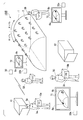
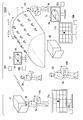
- FIG. 1 is a schematic diagram of a member attachment support system according to the first embodiment of the present invention.
- the member attachment support system 100 assists the workers 5A to 5D in attaching the heat retaining block 3a and the like to cover the surfaces of high-temperature devices (compressors, combustors, turbines, etc.) constituting the gas turbine.
- the casing 1 shown in FIG. 1 is an example of a high-temperature device.
- the workers 5A to 5D may be similarly described as the worker 5.
- the armbands 6A to 6D, the attachment positions 8a and 8b, and the RFID (radio frequency identifier) tags 10a and 10b may be similarly described as the armband 6, the attachment position 8, and the RFID tag 10, respectively.
- a plurality of devices 2 for fixing the heat retaining block 3 are provided on the surface of the casing 1.
- the device 2 is an eye plate.
- the heat retaining block 3 is formed, for example, by filling a laminate in which a heat insulating material and a metal plate material are laminated in a cubic bag.
- the bag is made of, for example, a glass cloth material woven of glass fibers.
- an RFID tag 10 is sewn on a glass cloth material.
- Information (attachment position information) on the position where the heat retaining block 3 is to be attached is recorded on the RFID tag 10.
- a fixing device for example, a hook
- the worker 5 attaches the heat retaining block 3 to the surface of the casing 1 by hanging the hook on the appliance 2.
- the surface of the casing 1 is covered with the heat retaining block.
- An appropriate mounting position of the heat retaining block 3 is determined. Therefore, the worker 5 needs to attach each heat retaining block 3 to the appliance 2 at an appropriate position.
- the member attachment support system 100 assists the worker 5 in attaching the heat retaining block 3 by indicating the position at which the heat retaining block 3 is to be attached.
- FIG. 1 shows an example in which the work area is divided into two work areas (area a and area b).
- the workers 5A and 5B are in charge of the area a, and the workers 5C and 5D are in charge of the area b.
- the worker 5A wears an armband 6A on his arm.
- the workers 5B to 5D wear armbands 6 on their arms (armbands 6B to 6D, respectively).
- the armband 6 is color-coded according to the work area in charge. For example, the armbands of the workers 5A and 5B (armbands 6A and 6B) are red. On the other hand, the armbands of the workers 5C and 5D (armbands 6C and 6D, respectively) are blue.
- the storage box 41 stores the heat retaining block 3 attached to the area a.
- the worker 5 ⁇ / b> A performs the work of carrying out the heat retaining block 3 from the storage 41.
- the worker 5B performs an operation of attaching the heat retaining block 3 carried out by the worker 5A to an appropriate position in the area a of the casing 1.
- the storage box 42 stores the heat retaining block 3 attached to the area b.
- the worker 5C carries out the work of carrying out the heat retaining block 3 from the storage 42.
- the worker 5D performs the work of receiving the heat retaining block 3 carried out by the worker 5C and attaching it to an appropriate position in the area b.
- the armband 6 is provided with an information processing terminal (not shown, a terminal 20 in FIG. 2 described later).
- the terminal 20 is, for example, a mobile terminal such as a smartphone having a display screen.
- the terminal 20 is fixed to the armband 6 so that the worker 5 can refer to the display screen.
- the display screen of the terminal 20 has an input function such as a touch panel.
- the terminal 20 has a function of an RFID reader. During the operation of the worker 5, the function of the RFID reader is activated.
- the information processing terminal worn by the worker 5A is referred to as a terminal 20A
- the terminals worn by the other workers 5B to 5D are referred to as terminals 20B to 20D.
- the terminal 20 is described.
- the worker 5A carries out the heat retaining block 3a from the storage 41.
- the terminal 20A communicates with the RFID tag 10a when the terminal 20A approaches the RFID 10a attached to the heat retaining block 3a.
- the terminal 20A acquires the attachment position information stored in the RFID tag 10a and transmits the information to the server device 30.
- the worker 5C carries out the heat retaining block 3b from the storage 42.
- the terminal 20C provided on the armband 6C of the worker 5C acquires the mounting position information from the RFID tag 10b of the heat retaining block 3b and transmits the information to the server device 30.
- the server device 30 generates a support image for displaying the mounting positions of the heat retaining blocks 3a and 3b on the casing 1, and transmits the generated support image to the monitors 71 to 73 and the terminals 20A to 20D.
- the monitors 71 to 73 display support images.
- the terminal 20 displays the support image on the display screen. For example, as shown on the monitor 71, the support image shows the outer shape of the casing 1 and the mounting positions 8a and 8b.
- the mounting position 8a indicates the mounting position of the heat retaining block 3a
- the mounting position 8b indicates the mounting position of the heat retaining block 3b.
- the mounting positions 8a and 8b are displayed in different colors to distinguish the mounting positions of the heat retaining blocks 3a and 3b.
- the mounting position 8a (area a) of the heat retaining block 3a assigned to the workers 5A and 5B is displayed in red.
- the mounting position 8b (area b) of the heat retaining block 3b assigned to the workers 5C and 5D is displayed in blue.
- the workers 5A and 5B can grasp the attachment position of the heat retaining block 3a from the display position of the attachment position 8a of the same color as the color of their armband.
- the workers 5C and 5D can grasp the mounting position of the heat retaining block 3b from the display position of the mounting position 8b displayed in the same color as their armband.
- the worker 5A passes the carried-out heat retaining block 3a to the worker 5B.
- the worker 5B attaches the heat retaining block 3a to the attachment position 8a of the area a with reference to the support image displayed on the monitor 72 and the terminal 20B.
- the worker 5C passes the carried-out heat retaining block 3b to the worker 5D.
- the worker 5D attaches the heat retaining block 3b to the attachment position 8b of the area b with reference to the support image displayed on the monitor 73 and the terminal 20D.
- the work efficiency of improving the work efficiency can be improved by assigning different workers 5 to carry out the operation of transporting the heat retaining block 3 from the storages 41 and 42 and the operation of attaching the heat retaining block 3 to the casing 1 so as to separate work.
- one worker 5A may take out the heat retaining block 3 from the storage 41 and attach it to the area a.
- the worker 5C may take out the heat retaining block 3 from the storage 42 and attach it to an appropriate position in the area b.
- the workers 5A to 5D refer to the monitors 71 to 73 and the support images displayed on the display screens of the terminals 20 provided on the respective armbands 6, and thereby, the heat insulation block 3 Can be easily grasped. As a result, it is possible to reduce the working time and improve the working efficiency.
- the worker 5B When attaching the heat retaining block 3a to the attachment position 8a, the worker 5B inputs attachment completion information to the terminal 20B.
- the terminal 20B transmits the mounting completion information of the heat retaining block 3a to the server device 30.
- the server device 30 stores that the mounting operation of the heat retaining block 3a is completed and that the worker 5B has performed the mounting operation.
- the server device 30 generates a support image reflecting the completion of attachment of the heat retaining block 3a.
- the server device 30 transmits the generated support image to the monitors 71 to 73 and the terminals 20A to 20D. In the newly generated support image, for example, the portion of the mounting position 81a is updated from red to gray indicating the completion of the operation.
- the worker 5 can grasp the progress of the mounting work.
- the workers 5C and 5D in charge of the area b can check the progress of the work by the workers 5A and 5B.
- the server device 30 stores that the worker 5B has performed the work of attaching the heat retaining block 3a. By counting the work history for each worker 5, the work performance of the worker 5 can be managed.
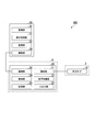
- FIG. 2 is a first block diagram illustrating an example of a member attachment support system according to the first embodiment of the present invention.
- the member attachment support system 100 includes an RFID tag 10 provided on the heat retaining block 3, a terminal 20 provided on the armband 6, and a server device 30.
- the member attachment support system 100 may further include a plurality of RFID tags 10 and a plurality of terminals 20.
- the RFID tag 10 stores mounting position information of the heat retaining block 3 to which the RFID tag 10 is mounted.
- the mounting position information is information including, for example, “11 of area a”.
- the area a is the work area (area information) described with reference to FIG.
- the address 11 is identification information of a section of a mounting position of the heat retaining block 3 uniquely set in the area a.
- the RFID tag 10 is a passive tag, is activated by being supplied with power by the terminal 20, and communicates with the terminal 20. In this communication, the RFID tag 10 transmits to the terminal 20 mounting position information including “11 of the area a”.
- the mounting position information includes area information and section information. For example, among the mounting positions 8a shown in FIG. 1 which are displayed in red, the red color indicates "area a" and the position where the mounting position 8a is displayed indicates "11." That is, the red color corresponds to the area information, and the mounting position 8a corresponds to the section information.
- the terminal 20 includes a reading unit 21, a display control unit 22, an input / output unit 23, a control unit 24, a storage unit 25, and a communication unit 26.
- the reading unit 21 activates the RFID tag 10 by induced electromotive force by wireless communication such as NFC (Near Field Communication) and communicates with the RFID tag 10.
- the reading unit 21 acquires the mounting position information stored in the RFID tag 10 through communication.
- the display control unit 22 generates an image to be displayed on the display screen of the terminal 20. For example, the display control unit 22 generates an image displaying buttons used for managing the progress of the mounting operation, such as “start”, “complete”, and “release”.
- the input / output unit 23 performs input / output to / from the terminal 20.
- the input / output unit 23 includes a display screen such as a liquid crystal display that displays an image generated by the display control unit 22, and a hardware button provided in the terminal 20.
- the display screen is provided with a touch panel for detecting finger contact, and the input / output unit 23 receives information input by the worker 5 via the touch panel.
- the control unit 24 controls the operation of the terminal 20 based on an operation performed by the worker 5 via the input / output unit 23 and the like. For example, when the worker 5 presses the “start” button displayed on the display screen, the control unit 24 starts the reading unit 21. When the worker 5 presses the “completion” button displayed on the display screen, the completion of the mounting operation of the heat retaining block 3 is transmitted to the server device 30 via the communication unit 26.
- the storage unit 25 stores various information.
- the communication unit 26 communicates with the server device 30 and other terminals 20 via a wireless LAN (local area network) or the like.
- the functional units included in the terminal 20A are described as a reading unit 21A, a display control unit 22A, an input / output unit 23A, a control unit 24A, a storage unit 25A, and a communication unit 26A.
- a reading unit 21A a display control unit 22A
- an input / output unit 23A a control unit 24A
- a storage unit 25A a storage unit 25A
- a communication unit 26A a communication unit.
- the server device 30 includes a management unit 31, a display control unit 32, a storage unit 33, and a communication unit 34.
- the management unit 31 records in the storage unit 33 the mounting position of the heat retaining block 3 on which the mounting operation has been completed.
- the display control unit 32 generates a support image to be displayed on the monitors 71 to 73 and the like.
- the storage unit 33 stores an outer shape image of the casing 1, information on a mounting position of the heat retaining block 3 on the surface of the casing 1, and the like. For example, the storage unit 33 stores that “11 in the area a” corresponds to the mounting position 8a of the casing 1 (FIG. 1).
- the communication unit 34 communicates with the terminal 20 and the monitors 71 to 73 via a wireless LAN (local area network) or the like.
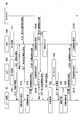
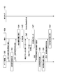
- FIG. 3 is a flowchart illustrating an example of the operation of the member attachment support system according to the first embodiment of the present invention.
- an application used for the attachment work is running on the terminal 20.
- the application displays, on the display screen of the terminal 20, buttons displaying text such as "start”, “complete”, and “release”, and a support image.
- the worker 5A presses the “start” button on the display screen of the terminal 20A.
- the control unit 24A activates the reading unit 21A (RFID function) (step S11).
- the control unit 24A notifies the activation of the reading unit 21A to the server device 30 via the communication unit 26A (step S12).
- the activation notification of the reading unit 21A includes the identification information of the terminal 20A.
- the control unit 24B activates the reading unit 21B (RFID function) (step S13).
- the control unit 24B notifies the server device 30 of the activation of the reading unit 21B via the communication unit 26B (Step S14).
- the activation notification of the reading unit 21B includes the identification information of the terminal 20B.
- the management unit 31 receives the activation notification of the reading units 21A and 21B via the communication unit 34.
- the management unit 31 records the identification information of the terminals 20A and 20B notified of the activation of the RFID function and the reception time of the activation notification (step S15). With this record, the worker 5 participating in the mounting work can be managed.
- the correspondence between the terminal 20A, the worker 5A and the work area (area a), and the correspondence between the terminal 20B and the worker 5B and the area a are registered in the storage unit 33 of the server device 30. It is registered in the storage unit 33 that the worker 5A carries out the heat retaining block and the worker 5B performs the work of attaching the heat retaining block.
- the worker 5A selects the heat insulation block 3 to be next attached in the storage 41, and carries out the selected heat insulation block 3.
- the reading unit 21A acquires the mounting position information from the RFID 10 of the selected heat retaining block 3 (Step S16).
- the reading unit 21A outputs the acquired mounting position information to the control unit 24A.
- the control unit 24A transmits the mounting position information together with the identification information of the terminal 20A to the server device 30 via the communication unit 26A (Step S17).
- the mounting position information includes information on the work area (area information) and section information indicating a mounting position in the work area.
- the display control unit 32 receives the notification of the attachment position information via the communication unit 34.
- the display control unit 32 generates a support image that displays the mounting position information (for example, the mounting position 8a) acquired from the terminal 20A on the casing 1 (Step S18).
- the display control unit 32 generates a support image in which the attachment position 8a is displayed in red.
- the display control unit 32 transmits the support image to the monitors 71 to 73 and the terminals 20A and 20B via the communication unit 34 (Steps S19A and S19B).
- the monitors 71 to 73 and the terminals 20A and 20B display support images (steps S20A and S20B).
- the workers 5A and 5B confirm the mounting position of the heat retaining block 3 with reference to the monitors 71 to 73 and the support image displayed on the display screen of each terminal 20.
- the management unit 31 records the identification information and the attachment position information of the terminal 20A in the storage unit 33 together with the time at which the information was received. Thereby, the work history indicating that the worker 5A has carried out the heat retaining block 3 can be recorded.
- the worker 5A passes the carried-out heat retaining block 3 to the worker 5B.
- the worker 5B receives the heat retaining block 3.
- the reading unit 21B acquires mounting position information from the received RFID 10 of the heat retaining block 3 (Step S21).
- the reading unit 21B outputs the acquired mounting position information to the control unit 24B.
- the control unit 24B transmits the attachment position information to the server device 30 via the communication unit 26B (Step S22).
- the worker 5A inputs information indicating that the heat insulation block 3 has been released (passed to the worker 5b) to the terminal 20A (step S23). For example, the worker 5A presses a “release” button on the display screen. Then, the control unit 24A notifies the server device 30 of the release of the heat retaining block 3 together with the identification information of the terminal 20A via the communication unit 26A (step S24).
- the management unit 31 records the identification information of the terminal 20A and the release notification in the storage unit 33 at the time of receiving the information.
- the management unit 31 records the identification information and the attachment position information of the terminal 20B in the storage unit 33 at the time when the information was received (step S25).
- a work history indicating that the worker 5A has delivered the heat retaining block 3 to the worker 5B can be recorded.
- the worker 5B When the worker 5B confirms the mounting position of the heat retaining block 3 with reference to the monitor 72 and the display screen of the terminal 20B, the worker 5B mounts the heat retaining block 3 at the position indicated by the support image.
- the worker 5B inputs information indicating that the mounting of the heat retaining block 3 is completed to the terminal 20B (step S26). For example, the worker 5B presses a “Done” button on the display screen.
- the control unit 24B notifies the server device 30 of the completion of the attachment of the heat retaining block 3 together with the identification information of the terminal 20B via the communication unit 26B (step S27).
- the management unit 31 records the identification information of the terminal 20B and the completion notification in the storage unit 33 at the time of receiving the information (step S28). Thereby, the work history indicating the completion of the attachment of the heat retaining block 3 to the casing 1 by the worker 5B can be recorded.
- the display control unit 32 When the attachment of the heat retaining block 3 is completed, the display control unit 32 generates a support image after the attachment is completed (Step S29). The display control unit 32 generates, for example, a support image in which the mounting position of the heat retaining block 3 in the casing 1 is displayed in gray.
- the display control unit 32 transmits the support image to the monitors 71 to 73 and the terminals 20A and 20B via the communication unit 34 (Steps S30A and S30B).
- the monitors 71 to 73 and the terminals 20A and 20B display support images (steps S31A and S31B).
- the workers 5A and 5B can check the positions where the mounting work has been performed with reference to the monitors 71 to 73 and the support images displayed on the display screens of the respective terminals 20.
- the work manager can check the progress of the mounting work.
- the process flow of the member mounting support system 100 according to the work by the workers 5A and 5B has been described.
- the workers 5C and 5D perform the work of mounting the heat retaining block 3 on the area b.
- the member mounting support system 100 performs the same processing and displays a support image displaying the mounting status of the heat retaining block 3 in the area a and the area b.
- all the workers 5 can perform the mounting work while sharing the progress of the work.
- the workers 5A and 5B can proceed with the mounting work on the area a while grasping the work situation of the other workers 5C and 5D.
- FIG. 4 is a diagram illustrating an example of a mounting position of the heat retaining block according to the first embodiment of the present invention.
- FIG. 4 is a cross-sectional view of the casing 1 illustrated in FIG. The work efficiency is good when the heat retaining block 3 is attached from the heat retaining block 3 attached at a lower position.
- Priority 1 to priority 5 are shown in ascending order of the priority of the mounting work.
- FIG. 5 is a diagram illustrating an example of a storage room of the heat retaining block according to the first embodiment of the present invention.
- FIG. 5 shows the storage state of the heat retaining block 3 in the storage box 41.
- shelves A to E are installed in the storage 41.
- the shelf A accommodates the heat insulating blocks 3 to be mounted most preferentially (priority 1).
- the shelf B accommodates the heat insulating blocks 3 of priority 2 is accommodated.
- the shelf C accommodates the heat insulating blocks 3 of the priority 3
- the shelves D and E accommodate the heat insulating blocks 3 of the priorities 4 and 5, respectively. By accommodating in this way, work efficiency can be improved.
- the worker 5A first carries out the heat retaining blocks 3 on the shelf A one after another and hands it over to the worker 5B.
- the worker 5B attaches all the heat retaining blocks 3 of the priority 1 in the area a of FIG.
- the worker 5A next carries out the heat retaining block 3 on the shelf B and delivers it to the worker 5B.
- the worker 5B attaches all the heat insulation blocks 3 of priority 2 in the area a.
- the heat retaining block 3 In the case where the heat retaining block 3 is stored in the storage 41, it is desirable to store the heat retaining block 3 in each shelf according to priority. For example, in a regular inspection or the like, all the heat retaining blocks 3 are removed and stored in the storages 41 and 42, and after the inspection work is completed, the heat retaining blocks 3 are carried out again from the storages 41 and 42 and attached to the casing 1.
- the worker 5B When removing the heat retaining block 3, it is assumed that the worker 5B performs the work of removing the heat retaining block 3 from the casing 1, passes the removed heat retaining block 3 to the worker 5A, and stores the worker 5A in the storage 41. Then, the worker 5B removes, for example, sequentially from the heat retaining block 3 associated with the priority 5 in FIG.
- the worker 5A stores the received heat retaining block 3 in the shelf E.
- the worker 5B removes each of the heat insulating blocks 3 of the priority 4, and the worker 5A stores the heat insulating blocks 3 on the shelf D.
- the worker 5A stores the thermal insulation block of priority 3 on the shelf C, the thermal insulation block of priority 2 on the shelf B, and the thermal insulation block of priority 1 on the shelf A.
- the order of attaching the heat retaining blocks 3 may be arbitrary. However, from the viewpoint of work efficiency, it is desirable to attach them in the order described in FIG. According to the accommodation method described with reference to FIG. 5, when the worker 5 ⁇ / b> A carries out the heat retaining block 3, it is possible to save the trouble of searching for the heat retaining block 3 to be carried out preferentially.
- the worker 5B can attach the heat retaining blocks 3 in an ideal order.
- the member mounting support system 100 since the (durable) RFID tag 10 is mounted on the heat retaining block 3, a support image is displayed every time the inspection work is performed, and the mounting work by the worker 5 is supported. can do. Even when the RFID tag 10 breaks down, the member attachment support system 100 can be used repeatedly by attaching the RFID tag 10 storing the appropriate attachment position information to the heat retaining block 3 again.
- the worker 5 ⁇ / b> A can search for the heat insulation block 3 with a high priority and carry it out by using the member attachment support system 100. For example, when the worker 5A approaches the heat retaining block 3, the mounting position of the heat retaining block 3 is displayed on the monitor 71 or the display screen of the terminal 20A. If the worker knows the priority shown in FIG. 4, the worker 5 ⁇ / b> A can grasp the priority of the heat insulation block 3 based on the mounting position of the heat insulation block 3 displayed on the support image. The worker 5A can select the high-priority heat retaining block 3 and pass it to the worker 5B.
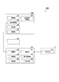
- FIG. 6 is a second block diagram illustrating an example of the member attachment support system according to the first embodiment of the present invention.
- the member mounting support system 100A does not include the server device 30.
- the terminal 20 includes a management unit 27, and records the completion time and the mounting position of the heat retaining block 3 in the storage unit 25.
- the display control unit 22 generates a support image.
- the slave device such as the terminal 20B notifies the mounting position information acquired from the RFID tag 10 (steps S17 and S22 in FIG. 3). Also, a release notification (step S24 in FIG.
- step S27 in FIG. 3 3) and a completion notification (step S27 in FIG. 3) are sent to the terminal 20A, which is the master device, and the terminal 20A generates a support image each time (step S18, FIG. S29) and progress recording (steps S25 and S28 in FIG. 3) may be performed to transmit the support image to the slave units and the monitors 71 to 73.
- the progress recording may be performed at each terminal 20, the results may be transmitted to each other and synchronized, and the support image may be generated at each terminal 20.
- the member mounting support system of the present embodiment can be realized.
- the monitors 71 to 73 are provided, but the monitors 71 to 73 are not essential.
- the process of FIG. 3 may be performed by displaying the support image on the display screen (input / output unit 23) of the terminal 20.
- the support image may be displayed only on the monitors 71 to 73 without displaying the support image on the display screen of the terminal 20.
- the terminal 20 need not have a display screen.
- the functions described above may be realized by associating the buttons (hardware) provided on the terminal 20 with “activation”, “release”, “completion”, and the like described above.
- the RFID tag 10 includes the attachment position information (area information, section information).
- the identification information of the RFID tag 10 is stored, and the server device 30 stores the identification information in the attachment position. You may comprise so that it may convert into information.
- the worker 5 reads the mounting position information stored in the RFID tag 10 of the heat retaining block 3 using the terminal 20 provided on the armband 6 and monitors the specific position of the mounting position on the monitor 71 or the like.
- the terminal 20 is fixedly installed, for example, near the monitor 71 or the like, and the worker 5 moves to the terminal 20 with the heat retaining block 3 and connects to the terminal 20.
- a reading device such as an RFID reader or a bar code reader reads the attachment position information and displays the result on a monitor 71 or the like.
- FIG. 7 is a schematic diagram of a member attachment support system according to the second embodiment of the present invention.
- the same reference numerals are given to the same components as the functional units configuring the member mounting support system 100 according to the first embodiment of the present invention, and Is omitted.
- the terminal 20 is fixedly installed at a predetermined position instead of the armband 6 of the workers 5A to 5D.
- the terminals 20a, 20b, and 20c are installed near monitors 71, 72, and 73, respectively.
- the terminals 20a to 20c may be portable terminals such as smartphones as in the first embodiment, but may be configured by stationary computers such as PCs (Personal Computers).
- the functional units included in the terminals 20a to 20c are the same as those described with reference to FIG. 2.
- an RFID reader or a barcode reader is connected to the terminals 20a to 20c, and these are read by the reading units 21a to 21c. May be configured.
- a keyboard and mouse (not shown) and monitors 71 to 73 (not shown) are connected to the terminals 20a to 20c, which may constitute the input / output unit 23a.
- the display control unit 22a of the terminal 20a Is displayed.
- the worker 5A carries out the heat retaining block 3a from the storage 41.
- the worker 5B receives the heat retaining block 3a from the worker 5A.
- the worker 5B carries, for example, the heat retaining block 3a near the monitor 72, and causes an RFID reader (not shown) connected to the terminal 20b to read the attachment position information stored in the RFID tag 10a.
- the terminal 20b acquires the mounting position information from the RFID tag 10a and transmits the information to the server device 30.
- the worker 5C carries out the heat retaining block 3b from the storage 42.
- the worker 5D receives the heat retaining block 3b from the worker 5C and approaches the RFID reader (reading unit 21c) (not shown) connected to the terminal 20c near the monitor 73. Then, the terminal 20c acquires the attachment position information stored in the RFID tag 10b read by the RFID reader and transmits the information to the server device 30.
- the server device 30 generates a support image that displays the mounting positions of the heat retaining blocks 3a and 3b on the casing 1, and transmits the generated support image to the terminals 20a to 20c and the monitors 71 to 73.
- the terminals 20a, 20b, and 20c display support images on their respective display screens.
- the monitors 71, 72, and 73 display support images.
- the worker 5B checks the mounting position displayed on the monitor 72, and mounts the heat retaining block 3a at the mounting position 8a in the area a.
- the worker 5D checks the attachment position displayed on the monitor 73, and attaches the heat retaining block 3b to the attachment position 8b in the area b.
- the terminals 20a and 20b notify the server device 30 of the completion of the attachment of the heat retaining blocks 3a and 3b together with the identification information of each terminal.
- the server device 30 records the work progress and generates a support image reflecting the work status.
- the terminals 20a to 20c and the monitors 71 to 73 receive the support image reflecting the work situation from the server device 30, and display the support image.
- the workers 5A to 5D can easily grasp the mounting position of the heat retaining block 3 without wearing the armband 6. Accordingly, with a system configuration that is simpler than in the first embodiment, the same effects as in the first embodiment, such as a reduction in the time for attaching the heat retaining block 3 and an improvement in work efficiency, can be obtained.
- a member attachment support system according to a third embodiment of the present invention will be described with reference to FIGS.
- the same components as those of the member attachment support systems 100 to 100B according to the first embodiment and the second embodiment of the present invention are denoted by the same reference numerals, and their respective descriptions are given. Is omitted.
- the member mounting support systems 100 to 100B provide a function of guiding the mounting position of the heat retaining block 3.
- the member mounting support system 100C according to the third embodiment provides a function of not only displaying the mounting position of the heat retaining block 3 but also storing and displaying the storage location of the removed heat retaining block 3.
- the operation of removing the heat retaining block 3 from the casing 1 and performing the work of attaching the heat retaining block 3 again after the inspection is performed.
- the function of displaying the storage location of the heat retaining block 3 can save the trouble of searching for the heat retaining block 3 when reattaching the heat retaining block 3 to the casing 1 after inspection.
- FIG. 8 is a block diagram illustrating an example of a member attachment support system according to the third embodiment of the present invention.
- the member attachment support system 100C includes an RFID tag 10, a terminal 20, a terminal 50, and a server device 30C provided in the heat retaining block 3.
- the configuration of the RFID tag 10 and the terminal 20 is the same as the configuration shown in the first embodiment and the second embodiment, and thus the description is omitted.
- the server device 30C includes a management unit 31, a display control unit 32, a storage unit 33, a communication unit 34, and a storage location recording unit 35.
- the accommodation location recording unit 35 records the location where the worker 5 accommodates the heat insulation blocks 3 for each heat insulation block 3.
- the terminal 50 includes a reading unit 51, a display control unit 52, an input / output unit 53, a control unit 54, a storage unit 55, and a communication unit 56.
- the terminal 50 is configured by a mobile terminal such as a smartphone or a stationary computer such as a PC.
- the reading unit 51 communicates with the RFID tag 10 by wireless communication such as NFC (Near Field Communication).
- the reading unit 51 acquires the attachment position information stored in the RFID tag 10 by communication.
- the reading unit 51 may be an RFID reader or a barcode reader connected to the terminal 50.
- the display control unit 52 generates an image to be displayed on the display screen of the terminal 50.
- the display control unit 52 generates an image that displays buttons used for storing and carrying out the heat retaining block, such as “start”, “storage start”, and “next”.
- the input / output unit 53 performs input / output to / from the terminal 50.
- the input / output unit 53 includes a display screen provided on the terminal 50, hardware buttons provided on the terminal 50, a touch panel provided on the display screen, a monitor connected to the terminal 50, a keyboard, and the like.
- the control unit 54 controls the operation of the terminal 50 based on an operation performed by the worker 5 via the input / output unit 53 and the like. For example, when the worker 5 presses an “activation” button displayed on the display screen, the control unit 54 activates the reading unit 51. When the worker 5 presses the “accommodation start” button displayed on the display screen, the start of the accommodation operation of the heat retaining block 3 is transmitted to the server device 30C via the communication unit 56.
- the storage unit 55 stores various information.
- the communication unit 56 communicates with the server device 30C via a wireless LAN (local area network) or the like.
- the functional units included in the terminal 50A will be described as a reading unit 51A, a display control unit 52A, an input / output unit 53A, a control unit 54A, a storage unit 55A, and a communication unit 56A.
- a reading unit 51A a display control unit 52A
- an input / output unit 53A a control unit 54A
- a storage unit 55A a storage unit 55A
- a communication unit 56A the terminal 50C.
- FIG. 9 is a first schematic diagram of a member attachment support system according to a third embodiment of the present invention.
- FIG. 9 shows a member attachment support system 100C of the present embodiment.
- a terminal 50A is provided on the armband 6A worn by the worker 5A
- a terminal 20B is provided on the armband 6B worn by the worker 5B.
- a terminal 50C is provided on the armband 6C worn by the worker 5C
- a terminal 20D is provided on the armband 6D worn by the worker 5D.
- the worker 5B removes the heat retaining block 3a from the area a of the casing 1.
- the worker 5A receives the heat retaining block 3a from the worker 5B and stores it in the storage 41.
- the worker 5D removes the heat retaining block 3b from the area b, and the worker 5C stores the heat retaining block 3b in the storage 42.
- Drawing 10 is a flow chart which shows an example of operation of a member attachment supporting system at the time of storage of a heat retention block concerning a third embodiment of the present invention.
- FIG. 11 is a diagram illustrating a recording process of a storage location of a heat retaining block according to the third embodiment of the present invention.
- the worker 5A inputs information indicating the start of the accommodation operation of the heat retaining block 3 to the terminal 50A, for example, by pressing a “accommodation start” button displayed on the display screen of the terminal 50A.
- the input / output unit 53A receives the input.
- the communication unit 56A notifies the server device 30C of the start of the accommodation work and the identification information of the terminal 50A (Step S41).
- FIG. 11A shows an example of the accommodation location image.
- FIG. 11A is, for example, a plan view of the storage case 41.
- the floor surface of the storage case 41 is divided into regions of a predetermined size, and identification numbers such as “P1” and “P2” are assigned to each region. It shows a state in which it is attached. “P1” and the like are places where one heat retaining block 3 is accommodated.
- the display control unit 32 generates a storage location image illustrated in FIG. 11A, and the communication unit 34 transmits the storage location image to the terminal 50A (step S43).
- the communication unit 56A receives the accommodation location image, and the display control unit 52A displays the accommodation location image on the display screen of the terminal 50A (step S44).
- the worker 5A presses the “start” button on the display screen of the terminal 50A.
- the control unit 54A activates the reading unit 51A (RFID function) (step S45).
- the worker 5B removes the heat retaining block 3a from the casing 1 and passes it to the worker 5A.
- the reading unit 51A acquires the mounting position information from the received RFID 10 of the heat retaining block 3 (Step S46).
- the mounting position information functions as identification information of the heat retaining block 3.
- the reading unit 51A outputs the acquired mounting position information to the control unit 54A.
- the worker 5A carries the received heat retaining block 3a to the storage 41 and places (stores) it in any place in the storage.
- the worker 5A selects a storage location (“P1”, “P2”, etc.) corresponding to the position where the heat retaining block 3 is placed from the storage location image displayed by the terminal 50A, and Is input (step S47).
- the input / output unit 53A receives this input, and outputs information on the selected accommodation location to the control unit 54A.
- the control unit 54A transmits the attachment position information and the information of the accommodation place (“P1” or the like) together with the identification information of the terminal 50A to the server device 30C via the communication unit 56A (Step S48).
- the accommodation location recording unit 35 acquires these pieces of information via the communication unit 34.
- the storage location recording unit 35 records the mounting location information (the identification information of the heat retaining block 3) and the information of the storage location in the storage unit 33 in association with each other (Step S49).
- FIG. 11B shows an example of a table in which information on accommodation places is recorded.
- the table stored in the storage unit 33 stores the attachment position information, the information on the storage location, and the attachment order in association with each other.
- the mounting order is determined in advance for each mounting position information. For example, as described with reference to FIG. 5, it is known that if the heat retaining block 3 is mounted in such an order in accordance with the mounting position, the work efficiency is improved.
- FIG. 5 it is known that if the heat retaining block 3 is mounted in such an order in accordance with the mounting position, the work efficiency is improved.
- the storage location recording unit 35 sends the “installation location information” field of the record having the value corresponding to the received mounting location information in the “installation location information” field. Store the received information on the accommodation location.
- the display control unit 32 updates the accommodation location image (step S50). For example, when “P1” is received as the information on the accommodation location, the display control unit 32 generates an accommodation location image in which the position of “P1” is grayed out.
- the communication unit 34 transmits the updated accommodation location image to the terminal 50A (step S51).
- the communication unit 56A receives the updated accommodation location image, and the display control unit 52A displays the updated accommodation location image (step S52).
- the worker 5A can confirm that the accommodation place of the heat retaining block 3 placed by the worker 5A has been recorded.
- the workers 5A and 5B repeat the same operation until all the heat retaining blocks 3 in the area a are removed and accommodated.
- the worker 5D removes the heat retaining block 3b
- the worker 5C repeats the operation of inputting the storage location to the terminal 50C while storing the heat retaining block 3b in the storage case 42.
- the terminal 50C transmits the mounting position information of the heat retaining block 3b and the information of the accommodation place to the server device 30C each time. In this way, when all the heat retaining blocks 3 are removed from the casing 1 and accommodated, information on the accommodation locations of all the heat retaining blocks 3 is recorded in the server device 30C.
- the worker 5A carries out the heat retaining block 3 from the storage 41 in a predetermined work order and hands it over to the worker 5B.
- the worker 5B mounts the received heat retaining block 3 at an appropriate mounting position in the area a.
- the worker 5C carries out the heat retaining block 3 from the storage 42, and the worker 5D receives the heat retaining block 3 and attaches the heat retaining block 3 to an appropriate mounting position in the area b.
- the installation work support by the workers 5B and 5D is the same as in the first embodiment.
- FIG. 12 is a flowchart illustrating an example of the operation of the member attachment support system when the heat retaining block according to the third embodiment of the present invention is carried out.
- the worker 5A inputs, to the terminal 50A, information indicating the start of the mounting operation of the heat retaining block 3a, for example, by pressing a “start mounting” button displayed on the display screen of the terminal 50A.
- the input / output unit 53A receives the input.
- the communication unit 56A notifies the server device 30C of the start of the mounting work and the identification information of the terminal 50A (Step S61).
- the communication unit 34 receives this notification.
- the display control unit 32 generates a storage location image indicating the storage location of the heat retaining block 3 to be attached first (step S62). Specifically, the display control unit 32 refers to the data whose mounting order is “1” from the table illustrated in FIG. 11B and reads out the mounting position information and the accommodation location information. Then, for example, when the heat retaining block 3 to be attached first is stored in “P8”, the display control unit 32 sets only “P8” in another area (in the storage location image illustrated in FIG. 11A). An image displayed in a mode different from “P1” or the like is generated.
- the display control unit 32 generates an image in which the characters and the background of P8 are displayed in a color different from those of the other areas, or are blinked to highlight.
- the communication unit 34 transmits the storage location image and the mounting position information (identification information) of the heat retaining block 3 to be mounted first to the terminal 50A (step S63).
- the communication unit 56A receives the storage location image
- the display control unit 52A displays the storage location image on the display screen of the terminal 50A (step S64).
- the worker 5A carries out the heat retaining block 3a from the location corresponding to “P8” in the storage 41 and transfers it to the worker 5B with reference to this display.
- the reading unit 51A of the terminal 50A reads the mounting position information from the RFID tag 10 of the heat retaining block 3a and obtains the mounting obtained from the server device 30C. It may be configured to collate with the position information and display an error message if they do not match.
- the worker 5B having received the heat retaining block 3a, reads the mounting position information of the heat retaining block 3a using the terminal 20B in the same manner as in the first embodiment, and displays the mounting position on the display screen or the monitor 72 of the terminal 20B. Display.
- the worker 5B mounts the heat retaining block 3 while referring to the mounting position displayed on the monitor 72 or the like.
- the worker 5A presses a “next” button displayed on the display screen of the terminal 50A, for example, so that the heat retaining block 3a is attached next.
- the information requesting the accommodation place of the block 3 is input to the terminal 50A.
- the input / output unit 53A accepts the input, and the communication unit 56A notifies the server device 30C of the information requesting the accommodation location of the next heat retaining block 3 and the identification information of the terminal 50A (step S65).
- the communication unit 34 receives this notification, and the display control unit 32 generates a storage location image indicating the storage location of the heat insulation block 3 to be next attached (step S66).
- the display control unit 32 refers to the table in FIG. 11B, specifies the record whose mounting order is “2”, and reads out the mounting position information and the accommodation location information. Then, the display control unit 32 generates a storage location image in which the next storage location is highlighted.
- the communication unit 34 transmits the storage location image and the mounting position information of the heat insulating block to be mounted next to the terminal 50A (step S67).
- the communication unit 56A receives the accommodation location image, and the display control unit 52A displays the accommodation location image on the display screen (Step S68).
- the worker 5A carries out the heat retaining block 3 to be mounted next with reference to this display, and delivers it to the worker 5B.
- the workers 5A and 5B repeat the same operation until all the heat retaining blocks 3a in the area a are attached.
- the server device 30C notifies the terminal 50C worn by the worker 5C of the storage location of the heat retaining block 3b in the order of attachment, and the worker 5C stores the heat retaining block 3b in accordance with the guidance. Carry out from 42.
- the worker 5D repeats the work of receiving the heat retaining block 3 from the worker 5C and attaching it to the area b.
- the worker 5 can grasp the accommodation place of the heat insulating block 3 to be mounted next, the worker 5 can find the heat insulating block 3 to be mounted next without hesitation. Thereby, the efficiency of the work of attaching the heat retaining block 3 can be improved.
- the worker 5 can accommodate the heat retaining blocks 3 removed from the casing 1 in an arbitrary place without arranging them in the mounting order as illustrated in FIG.
- the workers 5A and 5C that house and carry out the heat retaining block 3 and the workers 5B and 5D that remove and attach the heat retaining block 3 work together.
- the worker 5 may perform a series of operations of removing, storing, carrying out, and attaching the heat retaining block 3. In this case, for example, a function may be mounted on the terminal 50 on the terminal 20, and the worker 5 may wear the armband 6 provided with the terminal 20.
- the accommodation position is input to the terminal 50, that is, the accommodation and reading and the input of the accommodation place are performed as one set, but the present invention is not limited to this.
- reading and input of a storage location may be performed collectively after all the heat retaining blocks 3 have been stored.
- a specific worker 5 for example, worker 5A
- the accommodation place may be recorded. By doing so, the worker 5 who performs the accommodation work of the heat retaining block 3 does not need to perform the operation of recording the accommodation place.
- FIG. 13 is a second schematic diagram of the member attachment support system according to the third embodiment of the present invention.
- the armband 6A worn by the worker 5A is provided with a terminal 50A, and the worker 5B does not wear the armband 6.
- a terminal 50C is provided on the armband 6C worn by the worker 5C, and the worker 5D does not wear the armband 6.
- the worker 5A stores and carries out the heat retaining block 3a while operating the terminal 50A.
- the worker 5B carries the heat retaining block 3a received from the worker 5A, for example, to the terminal 20b, causes the reading unit 21b to read the RFID tag 10, and refers to the mounting position displayed on the monitor 72 to refer to the heat retaining block 3a. To the casing 1 at an appropriate position. The same applies to the workers 5C and 5D.
- the workers 5 ⁇ / b> B and 5 ⁇ / b> D can perform the mounting operation with light equipment without wearing the armband 6.
- the cost of the member attachment support system 100C1 can be reduced.
- FIG. 14 is a third schematic diagram of the member attachment support system according to the third embodiment of the present invention.
- the worker 5A does not wear the armband 6, and the worker 5B wears the armband 6B provided with the terminal 20B.
- the worker 5C does not wear the armband 6, and the worker 5D wears the armband 6D provided with the terminal 20C.
- the terminal 50 is fixedly installed near the monitor 71, and the workers 5A and 5C move to the position where the terminal 50 is installed with the heat retaining block 3, and the RFID reader connected to the terminal 50 (reading).
- Unit 51 reads the attachment position information. Further, it is possible to switch between the storage location image of the storage 41 and the storage location image of the storage 42, and the workers 5A and 5C input the planned storage location of the heat retaining block 3 on the spot. Then, the workers 5A and 5C store the heat retaining block 3 at the storage planned positions of the storages 41 and 42, respectively, which are input.
- the workers 5 ⁇ / b> A and 5 ⁇ / b> C may store the heat retaining block 3 after having the RFID reader read the mounting position information, and may input the actual storing position to the terminal 50 after the storing. In the case where the heat retaining block is attached, the worker 5A carries out the heat retaining block 3a while checking the accommodation location displayed on the monitor 71.
- the worker 5B causes the terminal 20B to read the RFID tag 10 for the heat retaining block 3a received from the worker 5A.
- the worker 5B attaches the heat retaining block 3a to an appropriate position of the casing 1 with reference to the attachment position displayed on the display screen of the terminal 20B.
- the terminal 50 and the monitor may be installed for each of the storage case 41 and the storage case 42.
- the next heat retaining block 3 is referred to by referring to the storage location image on the monitor 71. You can work while consulting where to house.
- FIG. 15 is a fourth schematic diagram of the member attachment support system according to the third embodiment of the present invention.
- the workers 5A to 5D do not wear the armband 6, the terminals 50a and 50b are fixedly installed near the monitors 71a and 71b, respectively, and the terminals 20b and 20c are respectively monitored. It is fixedly installed near 72, 73.
- the worker 5A moves to the position where the terminal 50a is installed with the heat retaining block 3, reads the attachment position information, and performs the accommodation work.
- the worker 5A carries out the heat retaining blocks 3a in the order of attachment based on the display on the monitor 71a.
- the worker 5B receives the heat retaining block 3a carried out by the worker 5A, moves to the position where the terminal 20b is installed, reads the mounting position information, and displays the mounting position on the monitor 72.
- the worker 5C uses the terminal 50b and the monitor 71B to house and carry out the heat retaining block 3b.
- the worker 5D performs the mounting operation using the terminal 20c and the monitor 73.
- the system can be introduced and operated more easily and at lower cost than the configurations illustrated in FIGS. 9, 13, and 14.
- the terminal 20 has the configuration illustrated in FIG. It is also possible to adopt a configuration in which the recording unit 35, the function of generating the storage location image of the display control unit 32, and the table of the storage unit 33 are mounted and the server device 30C is not provided.
- both the function of the terminal 20 and the function of the terminal 50 may be mounted on one terminal device, and this terminal device may be provided on the armband 6 or near the monitor 71 or the like.
- the RFID tag 10 in which the attachment position information is stored is attached to the heat retaining block 3, but instead of the RFID tag 10, code information (bar code) indicating the attachment position information is used.
- QR code registered trademark
- QR code registered trademark
- an application for reading code information is installed on the terminal 20 or the terminal 50, or a code reader (a barcode reader or the like) is mounted on the terminal 20 or the terminal 50 to read the mounting position information.
- the image may be displayed on a glass-type display.
- the functions of the terminal 20 and the terminal 50 may be implemented in a glass-type wearable terminal.
- the mounting position of the heat retaining block 3 may be displayed so as to overlap the actual casing 1.
- the mounting position of the heat retaining block 3 is displayed by displaying the support image, and the storage location of the heat retaining block 3 to be mounted next is displayed by the storage location image.
- the guidance may be provided by voice.
- a speaker connected (or built-in) to the terminal 50A of the armband 6A guides the accommodation place by voice, and the worker 5A carries out the heat retaining block 3a from the guided place and the worker. Hand over to 5B.
- the worker 5B uses the RFID reader connected to the terminal 20B of the armband 6B to read the attachment position information stored in the RFID tag 10a.
- the speaker built in (or connected to) the terminal 20B guides the mounting position (area information, section information) of the heat retaining block 3a by voice.
- the worker 5A can carry out the heat retaining block 3a without referring to the monitor 71 or the like.
- the worker 5B can perform the work of attaching the heat retaining block 3a without referring to the monitor 72 or the like.
- the terminal 20, the server device 30, and the terminal 50 are mounted on a computer including a processor such as a CPU (Central Processing Unit), a main storage device, an auxiliary storage device, an input / output interface, a communication interface, and the like.
- a processor such as a CPU (Central Processing Unit), a main storage device, an auxiliary storage device, an input / output interface, a communication interface, and the like.
- the operation of each functional unit described above is stored in the auxiliary storage device in the form of a program.
- the CPU reads the program from the auxiliary storage device, expands the program in the main storage device, and executes the above-described processing according to the program.
- the CPU secures a storage area in the main storage device according to the program.
- the CPU secures a storage area for storing the data being processed in the auxiliary storage device according to the program.
- the application destination of the member attachment support system of the present embodiment is not limited to the high-temperature devices that constitute the gas turbine.
- the label displaying the RFID tag 10 and the code information is an example of an identification information storage unit.
- the terminal 20 and the terminal 50 to which the RFID reader and the barcode reader are connected are examples of a terminal device.
- the monitors 71 to 73 and the display screen of the terminal 20 are examples of a display device.
- the storage unit 33 that stores the table illustrated in FIG.
- the mounting position information includes the area information and the section information.
- the workers 5A and 5C since the workers 5A and 5C do not need to know the section information, the workers 5A and 5C receive the information from the RFID tags 10a and 10b. Only the area information may be transmitted to the terminals 20A and 20C carried by the user. Then, only the area information may be displayed on the monitor 71 referred to by the workers 5A and 5C and the display devices of the terminals 20A and 20C.
- Only the section information may be transmitted from the RFID tags 10a and 10b to the terminals 20B and 20D carried by the workers 5B and 5D. Then, only the section information may be displayed on the monitors 72 and 73 referenced by the workers 5B and 5D and the display devices of the terminals 20B and 20D. Alternatively, the area information and the section information may be transmitted from the RFID tags 10a and 10b to the terminals 20B and 20D carried by the workers 5B and 5D.
- the operation of mounting the heat retaining member to the device can be made more efficient.
Landscapes
- Engineering & Computer Science (AREA)
- Mechanical Engineering (AREA)
- General Engineering & Computer Science (AREA)
- Physics & Mathematics (AREA)
- Combustion & Propulsion (AREA)
- General Physics & Mathematics (AREA)
- Chemical & Material Sciences (AREA)
- Business, Economics & Management (AREA)
- Theoretical Computer Science (AREA)
- Economics (AREA)
- Quality & Reliability (AREA)
- Manufacturing & Machinery (AREA)
- Human Resources & Organizations (AREA)
- Marketing (AREA)
- Strategic Management (AREA)
- Tourism & Hospitality (AREA)
- Automation & Control Theory (AREA)
- General Business, Economics & Management (AREA)
- Health & Medical Sciences (AREA)
- Accounting & Taxation (AREA)
- Finance (AREA)
- Development Economics (AREA)
- Entrepreneurship & Innovation (AREA)
- Operations Research (AREA)
- Primary Health Care (AREA)
- General Health & Medical Sciences (AREA)
- Human Computer Interaction (AREA)
- Testing And Monitoring For Control Systems (AREA)
- Cooling Or The Like Of Electrical Apparatus (AREA)
- Heat-Pump Type And Storage Water Heaters (AREA)
Abstract
Description
本願は、2018年8月22日に日本に出願された特願2018-155362号、および、2018年11月26日に日本に出願された特願2018-220349号に基づき優先権を主張し、その内容をここに援用する。
以下、本発明の第一実施形態による保温ブロックの取付作業について図1~図6を参照して説明する。
図1は、本発明の第一実施形態における部材取付支援システムの概略図である。
部材取付支援システム100は、作業員5A~5Dが、ガスタービンを構成する高温機器(圧縮機、燃焼器、タービンなど)の表面を被覆するために、保温ブロック3a等を取り付ける作業を支援する。図1に示すケーシング1は、高温機器の一例である。保温ブロック3a、3bを区別する必要が無い場合には、単に保温ブロック3と記載することがある。作業員5A~5Dについても同様に作業員5と記載することがある。腕章6A~6D、取付位置8a,8b、RFID(radio frequency identifier)タグ10a,10bについても同様に、それぞれ腕章6、取付位置8、RFIDタグ10と記載することがある。
次に作業員5A~5Dによる保温ブロック3の取り付け作業の流れを説明する。
ケーシング1は大型で保温ブロック3の取り付け範囲は広範囲にわたる。そこで、ケーシング1の表面を複数の作業エリアに分割して、各作業エリアを1人または複数の作業員5で担当する。図1は、2つの作業エリア(エリアa、エリアb)に分割した例を示している。作業員5A,5Bはエリアaを担当し、作業員5C,5Dはエリアbを担当する。作業員5Aは、腕に腕章6Aを装着している。同様に作業員5B~5Dは、腕に腕章6(それぞれ腕章6B~6D)を装着している。腕章6は、担当する作業エリアに応じて色分けされている。例えば、作業員5A,5Bの腕章(腕章6A,6B)は赤色である。一方、作業員5C,5Dの腕章(それぞれ腕章6C,6D)は青色である。
作業員5Bは、保温ブロック3aを取付位置8aに取り付けると、端末20Bに取付完了情報を入力する。端末20Bは、保温ブロック3aの取付完了情報をサーバ装置30へ送信する。サーバ装置30は、保温ブロック3aの取り付け作業が完了したことと、作業員5Bがその取り付け作業を行ったことを記憶する。サーバ装置30は、保温ブロック3aの取付完了を反映した支援画像を生成する。サーバ装置30は、生成した支援画像をモニタ71~73、端末20A~20Dへ送信する。新たに生成された支援画像では、例えば、取付位置81aの部分が赤色から作業完了を示す灰色に更新されている。これにより、作業員5は、取付作業の進捗状況を把握することができる。例えば、エリアbを担当する作業員5C,5Dは、作業員5A,5Bによる作業の進捗を確認することができる。また、サーバ装置30は、作業員5Bが保温ブロック3aの取り付け作業を行ったことを記憶している。作業員5ごとに作業履歴を集計することで、作業員5の作業実績を管理することができる。
図2は、本発明の第一実施形態における部材取付支援システムの一例を示す第1のブロック図である。
部材取付支援システム100は、保温ブロック3に設けられたRFIDタグ10と、腕章6に設けられた端末20と、サーバ装置30とを含む。部材取付支援システム100は、さらに複数のRFIDタグ10と複数の端末20を含んでいてもよい。
RFIDタグ10は、そのRFIDタグ10が装着された保温ブロック3の取付位置情報を記憶している。取付位置情報とは、例えば、「エリアaの11番地」などを含む情報である。エリアaとは、図1で説明した作業エリア(エリア情報)である。11番地とは、エリアa内で一意に設定された保温ブロック3の取り付け位置の区画の識別情報である。RFIDタグ10は、パッシブタグであり、端末20により給電されて起動し、端末20と通信を行う。RFIDタグ10は、この通信において、「エリアaの11番地」等を含む取付位置情報を端末20へ送信する。取付位置情報は、エリア情報と区画情報を含む。例えば、図1の取付位置8aが赤く表示されることのうち、赤色は「エリアa」を示し、取付位置8aが表示された位置は「11番地」を示す。つまり、赤色は、エリア情報に対応し、取付位置8aは区画情報に対応する。
読取部21は、NFC(Near Field Communication)等の無線通信によって、誘導起電力によりRFIDタグ10を起動させ、RFIDタグ10と通信を行う。読取部21は、通信により、RFIDタグ10が記憶する取付位置情報を取得する。
表示制御部22は、端末20の表示画面に表示する画像を生成する。例えば、表示制御部22は、「起動」、「完了」、「解放」など取り付け作業の進捗管理に用いるボタンを表示した画像を生成する。
入出力部23は、端末20への入出力を行う。例えば、入出力部23は、表示制御部22が生成した画像を表示する液晶ディスプレイなどの表示画面や、端末20に設けられたハードウェアのボタンを含む。表示画面には、指の接触を検知するタッチパネルが設置されており、入出力部23は、タッチパネルを介して作業員5が入力した情報を受け付ける。
記憶部25は、種々の情報を記憶する。
通信部26は、サーバ装置30や他の端末20と無線LAN(local area network)等により通信を行う。
以下、端末20Aが備える機能部を、読取部21A、表示制御部22A、入出力部23A、制御部24A、記憶部25A、通信部26Aのように記載する。端末20B~20Dについても同様である。
管理部31は、取り付け作業が完了した保温ブロック3の取付位置を記憶部33に記録する。
表示制御部32は、モニタ71~73等に表示する支援画像を生成する。
記憶部33は、ケーシング1の外形画像や、ケーシング1の表面における保温ブロック3の取付位置の情報などを記憶する。例えば、記憶部33には、「エリアaの11番地」がケーシング1の取付位置8a(図1)に対応することを記憶している。
通信部34は、端末20やモニタ71~73と無線LAN(local area network)等により通信を行う。
図3は、本発明の第一実施形態における部材取付支援システムの動作の一例を示すフローチャートである。
前提として、端末20では、取付作業に用いるアプリケーションが起動しているとする。当該アプリケーションは、端末20の表示画面に、例えば「起動」、「完了」、「解放」などの文言が表示されたボタンと、支援画像を表示する。
まず、作業員5Aが端末20Aの表示画面の「起動」ボタンを押下する。すると、制御部24Aは、読取部21A(RFIDの機能)を起動する(ステップS11)。制御部24Aは、読取部21Aの起動を、通信部26Aを介して、サーバ装置30へ通知する(ステップS12)。読取部21Aの起動通知には、端末20Aの識別情報が含まれている。
モニタ71~73、端末20A,20Bは支援画像を表示する(ステップS20A,S20B)。作業員5A,5Bは、モニタ71~73、各自の端末20の表示画面に表示された支援画像を参照して、保温ブロック3の取り付け位置を確認する。
モニタ71~73、端末20A,20Bは支援画像を表示する(ステップS31A,S31B)。作業員5A,5Bは、モニタ71~73、各自の端末20の表示画面に表示された支援画像を参照して、取付作業を行った位置を確認することができる。作業の管理者は、取付作業の進捗状況を確認することができる。
本実施形態によれば、複数の作業員5によって保温ブロック3を取り付ける作業を行う場合でも、全ての作業員5が作業の進捗状況を共有しながら、取り付け作業を行うことができる。例えば、作業員5A、5Bは、他の作業員5C、5Dによる作業状況を把握しながらエリアaに対する取り付け作業を進めることができる。
図4は、本発明の第一実施形態における保温ブロックの取り付け位置の一例を示す図である。
図4は、図1に例示するケーシング1の断面図である。保温ブロック3は、より低い位置に取り付ける保温ブロック3から取り付けると作業効率が良い。取り付け作業の優先度が高いものから順に優先度1~優先度5を示してある。
図5に、収容庫41における保温ブロック3の収容状況を示す。収容庫41には、棚A~棚Eが設置されている。図4に示す優先度順で保温ブロックを取り付けるために、例えば、棚Aには、最も優先的に(優先度1)取り付けるべき保温ブロック3が収容されている。棚Bには、優先度2の保温ブロック3が収容されている。同様に棚Cには優先度3の保温ブロック3が収容され、棚D、Eには、それぞれ優先度4、5の保温ブロック3が収容されている。このように収容することにより、作業効率を改善することができる。
例えば、作業員5Aは、まず棚Aの保温ブロック3を次々と運び出して作業員5Bに渡す。作業員5Bは、図4のエリアaにおける優先度1の全ての保温ブロック3を取り付ける。棚Aが完了すると、次に作業員5Aは、棚Bの保温ブロック3を運び出して作業員5Bに渡す。作業員5Bは、エリアaにおける優先度2の全ての保温ブロック3を取り付ける。優先度3~5についても同様である。このようにすることにより、作業員5Bは、優先度の高い順に保温ブロック3を取り付けることができる。
以下、同様にして作業員5Aは、優先度3の保温ブロックを棚Cへ、優先度2の保温ブロックを棚Bへ、優先度1の保温ブロックを棚Aへ収容する。
図6は、本発明の第一実施形態における部材取付支援システムの一例を示す第2のブロック図である。
部材取付支援システム100Aは、サーバ装置30を含まない。代わりに端末20が管理部27を備え、保温ブロック3の取付完了時刻や取付位置を記憶部25に記録する。表示制御部22が、支援画像を生成する。例えば、端末20Aをマスタ機、端末20B等の他の端末20をスレーブ機として、端末20B等のスレーブ機が、RFIDタグ10から取得した取付位置情報の通知(図3のステップS17,ステップS22)や、解放通知(図3のステップS24)、完了通知(図3のステップS27)をマスタ機である端末20Aに対して行い、端末20Aがその都度、支援画像の生成(図3のステップS18,S29)や進捗記録(図3のステップS25,S28)を行って、スレーブ機やモニタ71~73へ支援画像を送信してもよい。あるいは、各端末20で進捗記録を行って、その結果を互いに送信しあって同期し、各端末20で支援画像を生成してもよい。
このようにサーバ装置が無くても、本実施形態の部材取付支援システムを実現することができる。
以下、本発明の第二実施形態による部材取付支援システムについて図7を参照して説明する。第一実施形態では、作業員5が、腕章6に設けられた端末20を用いて、保温ブロック3のRFIDタグ10が記憶する取付位置情報を読み取り、取付位置の具体的な場所をモニタ71等で確認する例を用いて説明を行った。第二実施形態においては、端末20を、例えば、モニタ71等の付近に固定して設置し、作業員5が、保温ブロック3を持って、端末20の場所まで移動して、端末20に接続されたRFIDリーダやバーコードリーダなどの読み取り装置(読取部21)に、取付位置情報を読み取らせて、その結果をモニタ71等に表示する構成とする。
本発明の第二実施形態に係る部材取付支援システム100Bの構成のうち、本発明の第一実施形態に係る部材取付支援システム100を構成する機能部と同じものには同じ符号を付し、それぞれの説明を省略する。本実施形態の部材取付支援システム100Bでは、端末20が、作業員5A~5Dの腕章6ではなく、所定の位置に固定して設置されている。例えば、端末20a、20b、20cは、それぞれモニタ71、72、73の近くに設置されている。端末20a~20cは、第一実施形態と同様にスマートフォン等の携帯端末であってもよいが、PC(Personal Computer)等の据え置き型のコンピュータによって構成されていてもよい。端末20a~20cが備える機能部は、図2を用いて説明したものと同様であるが、例えば、端末20a~20cには、RFIDリーダやバーコードリーダが接続され、これらが読取部21a~21cを構成していてもよい。端末20a~20cには、図示しないキーボード及びマウス、モニタ71~73が接続され、これらが入出力部23aを構成していてもよく、例えば、端末20aの表示制御部22aは、モニタ71に画像を表示する。
部材取付支援システム100Bの動作について説明する。例えば、作業員5Aは、収容庫41から保温ブロック3aを運び出す。作業員5Bは、作業員5Aからその保温ブロック3aを受け取る。作業員5Bは、例えば、モニタ72の近くまで保温ブロック3aを運び、端末20bに接続されたRFIDリーダ(図示せず)に、RFIDタグ10aが記憶する取付位置情報を読み取らせる。端末20bは、RFIDタグ10aから取付位置情報を取得し、サーバ装置30へ送信する。
以下、本発明の第三実施形態による部材取付支援システムについて、図8~図15を参照して説明する。本発明の第三実施形態に係る構成のうち、本発明の第一実施形態、第二実施形態に係る部材取付支援システム100~100Bの構成と同じものには同じ符号を付し、それぞれの説明を省略する。上記のように部材取付支援システム100~100Bは、保温ブロック3の取り付け位置を案内する機能を提供する。これに対し、第三実施形態に係る部材取付支援システム100Cは、保温ブロック3の取り付け位置を表示するだけではなく、取り外した保温ブロック3の収容場所を記憶し、表示する機能を提供する。例えば、定期点検時には、保温ブロック3をケーシング1から取り外し、点検後に再び保温ブロック3を取り付ける作業を行う。保温ブロック3の収容場所を表示する機能によって、点検後に保温ブロック3をケーシング1に再び取り付けるときに、保温ブロック3を探す手間を省くことができる。
部材取付支援システム100Cは、保温ブロック3に設けられたRFIDタグ10と、端末20と、端末50と、サーバ装置30Cとを含む。
RFIDタグ10、端末20については、第一実施形態、第二実施形態に示す構成と同様のため説明を省略する。
サーバ装置30Cは、管理部31と、表示制御部32と、記憶部33と、通信部34と、収容場所記録部35と、を備える。
収容場所記録部35は、作業員5が保温ブロック3を収容した場所を、保温ブロック3ごとに記録する。
読取部51は、NFC(Near Field Communication)等の無線通信によって、RFIDタグ10と通信を行う。読取部51は、通信により、RFIDタグ10が記憶する取付位置情報を取得する。読取部51は、端末50に接続されたRFIDリーダやバーコードリーダであってもよい。
表示制御部52は、端末50の表示画面に表示する画像を生成する。例えば、表示制御部52は、「起動」、「収容開始」、「次へ」など保温ブロックの収容と運び出しに用いるボタンを表示した画像を生成する。
入出力部53は、端末50への入出力を行う。例えば、入出力部53は、端末50に設けられた表示画面や、端末50に設けられたハードウェアのボタン、表示画面に設けられたタッチパネル、端末50に接続されたモニタ、キーボードなどを含む。
記憶部55は、種々の情報を記憶する。
通信部56は、サーバ装置30Cと無線LAN(local area network)等により通信を行う。
以下、端末50Aが備える機能部を、読取部51A、表示制御部52A、入出力部53A、制御部54A、記憶部55A、通信部56Aのように記載する。端末50Cについても同様である。
図9に本実施形態の部材取付支援システム100Cを示す。図1の構成と異なり、作業員5Aが装着する腕章6Aには、端末50Aが設けられ、作業員5Bが装着する腕章6Bには、端末20Bが設けられている。作業員5Cが装着する腕章6Cには、端末50Cが設けられ、作業員5Dが装着する腕章6Dには、端末20Dが設けられている。
まず、保温ブロック3を取り外す場面について説明する。例えば、定期点検の開始時に作業員5Bがケーシング1のエリアaから保温ブロック3aを取り外す。作業員5Aは、その保温ブロック3aを作業員5Bから受け取って収容庫41に収容する。同様に作業員5Dがエリアbから保温ブロック3bを取り外し、作業員5Cがその保温ブロック3bを収容庫42に収容する。
図11は、本発明の第三実施形態に係る保温ブロックの収容場所の記録処理を説明する図である。
まず、作業員5Aは、例えば、端末50Aの表示画面に表示された「収容開始」ボタンを押下する等して、保温ブロック3の収容作業の開始を示す情報を端末50Aに入力する。端末50Aでは、入出力部53Aがその入力を受け付ける。通信部56Aは、収容作業の開始と端末50Aの識別情報とをサーバ装置30Cに通知する(ステップS41)。サーバ装置30Cでは、通信部34がこの通知を受信する。また、表示制御部32が、収容場所画像を生成する(ステップS42)。図11(a)に収容場所画像の一例を示す。図11(a)は、例えば、収容庫41の平面図であり、収容庫41の床面を所定の大きさの領域に区分けして各領域に「P1」、「P2」等の識別番号を付した様子を示している。
「P1」等は、1つの保温ブロック3を収容する場所である。表示制御部32は、図11(a)に例示する収容場所画像を生成し、通信部34が収容場所画像を端末50Aに送信する(ステップS43)。端末50Aでは、通信部56Aが収容場所画像を受信し、表示制御部52Aが端末50Aの表示画面に収容場所画像を表示する(ステップS44)。
また、作業員5Aが端末50Aの表示画面の「起動」ボタンを押下する。すると、制御部54Aは、読取部51A(RFIDの機能)を起動する(ステップS45)。
次に点検後に保温ブロック3をケーシング1に取り付ける作業について説明する。作業員5Aは、収容庫41から予め定められた作業順に保温ブロック3を運び出し、作業員5Bに渡す。作業員5Bは、受け取った保温ブロック3をエリアaの適切な取付位置に取り付ける。同様に作業員5Cは、収容庫42から保温ブロック3を運び出し、作業員5Dがその保温ブロック3を受け取って、エリアbの適切な取付位置に取り付ける。作業員5B、5Dによる取付作業支援については、第一実施形態と同様である。
まず、作業員5Aは、例えば、端末50Aの表示画面に表示された「取付開始」ボタンを押下する等して、保温ブロック3aの取り付け作業の開始を示す情報を端末50Aに入力する。端末50Aでは、入出力部53Aがその入力を受け付ける。通信部56Aは、取り付け作業の開始と端末50Aの識別情報とをサーバ装置30Cに通知する(ステップS61)。サーバ装置30Cでは、通信部34がこの通知を受信する。すると、表示制御部32が、最初に取り付けるべき保温ブロック3の収容場所を示す収容場所画像を生成する(ステップS62)。具体的には、表示制御部32は、図11(b)に例示するテーブルから取り付け順が「1」のデータを参照し、取付位置情報と収容場所情報を読み出す。そして、例えば、最初に取り付けるべき保温ブロック3が「P8」に収容されている場合、表示制御部32は、図11(a)に例示する収容場所画像において、「P8」だけを他の領域(「P1」など)とは異なる態様で表示した画像を生成する。例えば、表示制御部32は、P8の文字や背景を他の領域とは異なる色で表示したり、点滅させたりして強調表示した画像を生成する。通信部34は、この収容場所画像と最初に取り付けるべき保温ブロック3の取付位置情報(識別情報)を端末50Aに送信する(ステップS63)。端末50Aでは、通信部56Aが収容場所画像を受信し、表示制御部52Aが、端末50Aの表示画面に収容場所画像を表示する(ステップS64)。作業員5Aは、この表示を参照して、収容庫41内の「P8」に対応する場所から保温ブロック3aを運び出して、作業員5Bに渡す。
上記説明では、保温ブロック3を収容したり運び出したりする作業員5A、5Cと、保温ブロック3の取り外しと取り付けを行う作業員5B、5Dとが協同して作業を行うこととしたが、一人の作業員5が、保温ブロック3の取り外し、収容、運び出し、取り付けという一連の作業を行ってもよい。その場合、例えば、端末20に端末50に機能を実装し、作業員5は、その端末20が備えられた腕章6を装着するようにしてもよい。
図13は、本発明の第三実施形態における部材取付支援システムの第2の概略図である。図13に示す部材取付支援システム100C1では、図9の構成と異なり、作業員5Aが装着する腕章6Aには、端末50Aが設けられ、作業員5Bは腕章6を装着していない。作業員5Cが装着する腕章6Cには、端末50Cが設けられ、作業員5Dは腕章6を装着していない。このような構成の場合、作業員5Aは、端末50Aを操作しながら、保温ブロック3aの収容と運び出しを行う。作業員5Bは、作業員5Aから受け取った保温ブロック3aを、例えば、端末20bまで運び、読取部21bにRFIDタグ10を読み取らせ、モニタ72に表示される取付位置を参照して、保温ブロック3aをケーシング1の適切な位置へ取り付ける。作業員5C,5Dについても同様である。
図14は、本発明の第三実施形態における部材取付支援システムの第3の概略図である。図14に示す部材取付支援システム100C2では、図13の構成と異なり、作業員5Aは腕章6を装着せず、作業員5Bは、端末20Bが設けられた腕章6Bを装着している。作業員5Cは腕章6を装着せず、作業員5Dは、端末20Cが設けられた腕章6Dを装着している。モニタ71の近くに端末50を固定して設置し、作業員5A、5Cは、保温ブロック3を持って端末50が設置された位置まで移動して、端末50に接続されたRFIDリーダ等(読取部51)に取付位置情報を読み取らせる。さらに収容庫41の収容場所画像と収容庫42の収容場所画像を切り替えられるようにしておき、作業員5A、5Cが、その場で保温ブロック3の収容予定位置を入力する。そして、作業員5A、5Cはそれぞれが入力した収容庫41、42の収容予定位置に保温ブロック3を収容する。あるいは、作業員5A、5Cは、RFIDリーダに取付位置情報を読み取らせた後に保温ブロック3を収容し、収容後に、実際の収容位置を端末50へ入力してもよい。保温ブロックを取り付ける場面では、作業員5Aは、モニタ71に表示された収容場所を確認しながら保温ブロック3aの運び出しを行う。作業員5Bは、作業員5Aから受け取った保温ブロック3aについて、端末20BにRFIDタグ10を読み取らせる。作業員5Bは、端末20Bの表示画面に表示される取付位置を参照して、保温ブロック3aをケーシング1の適切な位置へ取り付ける。作業員5C,5Dについても同様である。次に図15に例示するように端末50及びモニタは、収容庫41と収容庫42のそれぞれについて設置してもよい。
図15は、本発明の第三実施形態における部材取付支援システムの第4の概略図である。図15に示す部材取付支援システム100C3では、作業員5A~5Dは腕章6を装着せず、端末50a、50bがそれぞれモニタ71a、71bの近くに固定して設置され、端末20b、20cがそれぞれモニタ72、73の近くに固定して設置される。
作業員5Aは、保温ブロック3を持って端末50aが設置された位置まで移動して、取付位置情報を読み取らせて収容作業を行う。また、作業員5Aは、モニタ71aの表示に基づいて、保温ブロック3aを取り付け順に運び出す。そして、作業員5Bは、作業員5Aが運び出した保温ブロック3aを受け取って端末20bが設置された位置まで移動して、取付位置情報を読み取らせ、モニタ72にその取付位置を表示させる。
同様に作業員5Cは、端末50b、モニタ71Bを用いて保温ブロック3bの収容と運び出しを行う。作業員5Dは、端末20cとモニタ73を用いて取付作業を行う。
第三実施形態において、1つの端末装置に端末20の機能と端末50の機能の両方を実装し、この端末装置を腕章6に設けたり、モニタ71等の近くに設置したりしてもよい。
上記実施形態では、支援画像の表示により保温ブロック3の取り付け位置を表示し、収容場所画像により次に取り付けるべき保温ブロック3の収容場所を表示することとしたが、音声によって案内してもよい。例えば、図9の構成の場合、腕章6Aの端末50Aに接続(または内蔵)されたスピーカが収容場所を音声により案内し、作業員5Aは、案内された場所から保温ブロック3aを運び出して作業員5Bに渡す。作業員5Bは、腕章6Bの端末20Bに接続されたRFIDリーダを用いてRFIDタグ10aが記憶する取付位置情報を読み取らせる。すると、端末20Bに内蔵(または接続)されたスピーカは、保温ブロック3aの取付位置(エリア情報、区画情報)を音声により案内する。音声案内により、作業員5Aは、モニタ71等を参照することなく保温ブロック3aの運び出しができる。作業員5Bは、モニタ72等を参照することなく保温ブロック3aの取り付け作業を行うことができる。
例えば、本実施形態の部材取付支援システム適用先は、ガスタービンを構成する高温機器に限定されない。RFIDタグ10やコード情報を表示したラベルは、識別情報記憶部の一例である。RFIDリーダやバーコードリーダが接続された端末20および端末50は、端末装置の一例である。モニタ71~73、端末20の表示画面は表示装置の一例である。図11(b)に例示するテーブルを記憶する記憶部33は収容場所記憶部の一例である。端末20に接続されたスピーカまたは内蔵されたスピーカ、端末50に接続されたスピーカまたは内蔵されたスピーカは音声出力装置の一例である。
上記の実施形態では、取付位置情報は、エリア情報と区画情報を含むこととしたが、作業員5A、5Cは区画情報を知らなくてもよいので、RFIDタグ10a,10bから作業員5A、5Cが携帯する端末20A、20Cには、エリア情報だけが送信されてもよい。そして、作業員5A、5Cが参照するモニタ71と、端末20A、20Cの表示装置には、エリア情報だけが表示されてもよい。RFIDタグ10a,10bから作業員5B、5Dが携帯する端末20B、20Dには、区画情報だけが送信されてもよい。そして、作業員5B、5Dが参照するモニタ72,73と、端末20B、20Dの表示装置には、区画情報だけが表示されてもよい。あるいは、RFIDタグ10a,10bから作業員5B、5Dが携帯する端末20B、20Dには、エリア情報と区画情報が送信されてもよい。
2 器具
3、3a、3b 保温ブロック
5、5A、5B、5C、5D 作業員
6、6A、6B、6C、6D 腕章
8、8a、8b 取付位置
10、10a、10b RFIDタグ
20、20A、20B、20a、20b、20c 端末
21、21A、21B 読取部
22、22A、22B 表示制御部
23、23A、23B 入出力部
24、24A、24B 制御部
25、25A、25B 記憶部
26、26A、26B 通信部
27A、27B 管理部
30 サーバ装置
31 管理部
32 表示制御部
33 記憶部
34 通信部
41、42 収容庫
50、50A、50B 端末
51、51A 読取部
52、52A 表示制御部
53、53A 入出力部
54、54A 制御部
55、55A 記憶部
56、56A 通信部
71、72、73 モニタ
100、100A 部材取付支援システム
Claims (13)
- 複数の部材を機器に取り付ける作業を支援する部材取付支援システムであって、
複数の前記部材ごとに設けられ、前記部材の取付位置に関連付けられた識別情報を記憶する識別情報記憶部と、
前記識別情報記憶部から前記識別情報を取得する端末装置と、
前記端末装置が取得した前記識別情報に対応する前記機器における取付位置を示す支援画像を表示する表示装置と、
を備える部材取付支援システム。 - 前記識別情報には、前記機器における所定の作業エリアを示すエリア情報が含まれる、
請求項1に記載の部材取付支援システム。 - 前記識別情報には、前記作業エリア内における区画情報が含まれる、
請求項2に記載の部材取付支援システム。 - 前記表示装置は、前記機器における前記取付位置を、前記作業エリアに応じて異なる態様で表示する、
請求項2または請求項3に記載の部材取付支援システム。 - 前記部材が前記識別情報に対応する取付位置に取り付けられたことを記録する管理部、
をさらに備える請求項1から請求項4の何れか1項に記載の部材取付支援システム。 - 前記管理部の記録に基づいて、前記表示装置に他の作業員による前記作業の最新の進捗を表示する、
請求項5に記載の部材取付支援システム。 - 複数の前記識別情報記憶部と、
一つまたは複数の前記端末装置と、
前記識別情報を前記端末装置から取得し、前記支援画像を生成するサーバ装置と、
複数の作業員が同時に視認することができる前記表示装置と、
を備える請求項1から請求項6の何れか1項に記載の部材取付支援システム。 - 複数の前記識別情報記憶部と、
複数の前記端末装置と、
を備え、
前記端末装置のうちの少なくとも1台が前記支援画像を生成し、当該支援画像を残りの前記端末装置へ送信する、
請求項1から請求項6の何れか1項に記載の部材取付支援システム。 - 前記機器に取り付けられる前の前記部材の収容場所を記憶する収容場所記憶部、をさらに備え、前記表示装置は、前記収容場所を表示する、
請求項1から請求項8の何れか1項に記載の部材取付支援システム。 - 複数の部材を機器に取り付ける作業を支援する部材取付支援システムであって、
複数の前記部材ごとに設けられ、前記部材の取付位置に関連付けられた識別情報を記憶する識別情報記憶部と、
前記識別情報記憶部から前記識別情報を取得する端末装置と、
前記端末装置が取得した前記識別情報に対応する前記機器における取付位置を示す音声情報を出力する音声出力装置と、
を備える部材取付支援システム。 - 前記識別情報記憶部は、RFIDタグである、
請求項1から請求項10の何れか1項に記載の部材取付支援システム。 - 前記識別情報記憶部は、コード情報が表示された部材である、
請求項1から請求項10の何れか1項に記載の部材取付支援システム。 - 複数の部材を機器に取り付ける作業を支援する部材取付支援方法であって、
複数の前記部材ごとに設けられ、前記部材の取付位置に関連付けられた識別情報を記憶する識別情報記憶部から、端末装置によって、前記識別情報を取得するステップと、
前記端末装置が取得した前記識別情報に対応する前記機器における取付位置を示す支援画像を表示するステップと、
を有する部材取付支援方法。
Priority Applications (5)
| Application Number | Priority Date | Filing Date | Title |
|---|---|---|---|
| KR1020217000628A KR102513053B1 (ko) | 2018-08-22 | 2019-06-26 | 부재 취부 지원 시스템 및 부재 취부 지원 방법 |
| MX2021000559A MX2021000559A (es) | 2018-08-22 | 2019-06-26 | Sistema de soporte de fijacion de miembro y metodo de soporte de fijacion de miembro. |
| DE112019004192.4T DE112019004192B4 (de) | 2018-08-22 | 2019-06-26 | Gliedanbringungsunterstützungssystem und Gliedanbringungsunterstützungsverfahren |
| CN201980046160.0A CN112384327B (zh) | 2018-08-22 | 2019-06-26 | 构件装配辅助系统以及构件装配辅助方法 |
| US17/259,266 US12367455B2 (en) | 2018-08-22 | 2019-06-26 | Member attachment support system and member attachment support method |
Applications Claiming Priority (4)
| Application Number | Priority Date | Filing Date | Title |
|---|---|---|---|
| JP2018155362 | 2018-08-22 | ||
| JP2018-155362 | 2018-08-22 | ||
| JP2018220349A JP7191659B2 (ja) | 2018-08-22 | 2018-11-26 | 部材取付支援システム及び部材取付支援方法 |
| JP2018-220349 | 2018-11-26 |
Publications (1)
| Publication Number | Publication Date |
|---|---|
| WO2020039737A1 true WO2020039737A1 (ja) | 2020-02-27 |
Family
ID=69592622
Family Applications (1)
| Application Number | Title | Priority Date | Filing Date |
|---|---|---|---|
| PCT/JP2019/025357 Ceased WO2020039737A1 (ja) | 2018-08-22 | 2019-06-26 | 部材取付支援システム及び部材取付支援方法 |
Country Status (3)
| Country | Link |
|---|---|
| MX (1) | MX2021000559A (ja) |
| TW (1) | TWI753272B (ja) |
| WO (1) | WO2020039737A1 (ja) |
Citations (6)
| Publication number | Priority date | Publication date | Assignee | Title |
|---|---|---|---|---|
| JPH05278806A (ja) * | 1992-04-03 | 1993-10-26 | Nissan Motor Co Ltd | 在庫管理装置 |
| JP2007087249A (ja) * | 2005-09-26 | 2007-04-05 | Honda Motor Co Ltd | 組み付け管理システムおよびプログラム |
| JP2008001481A (ja) * | 2006-06-23 | 2008-01-10 | Twintec:Kk | オーダーピッキング装置 |
| WO2015063884A1 (ja) * | 2013-10-30 | 2015-05-07 | 株式会社日立製作所 | 生産管理システム、及び生産管理方法 |
| JP2016221671A (ja) * | 2015-06-02 | 2016-12-28 | 株式会社リコー | 作業指示システム、画像処理装置、情報処理方法及びプログラム |
| CN107423650A (zh) * | 2017-08-09 | 2017-12-01 | 青岛理工大学 | 一种投影式增强现实装配诱导与监测系统及其实现方法 |
Family Cites Families (3)
| Publication number | Priority date | Publication date | Assignee | Title |
|---|---|---|---|---|
| US5453933A (en) * | 1993-09-08 | 1995-09-26 | Hurco Companies, Inc. | CNC control system |
| US7849721B2 (en) * | 2004-09-10 | 2010-12-14 | Hy-Ko Products Company | Radio frequency identification (RFID) system for manufacturing distribution and retailing of keys |
| EP2809482B1 (en) * | 2012-01-30 | 2018-11-07 | Fatigue Technology, Inc. | Processing systems and method of operating the same |
-
2019
- 2019-06-26 WO PCT/JP2019/025357 patent/WO2020039737A1/ja not_active Ceased
- 2019-06-26 MX MX2021000559A patent/MX2021000559A/es unknown
- 2019-06-27 TW TW108122600A patent/TWI753272B/zh active
Patent Citations (6)
| Publication number | Priority date | Publication date | Assignee | Title |
|---|---|---|---|---|
| JPH05278806A (ja) * | 1992-04-03 | 1993-10-26 | Nissan Motor Co Ltd | 在庫管理装置 |
| JP2007087249A (ja) * | 2005-09-26 | 2007-04-05 | Honda Motor Co Ltd | 組み付け管理システムおよびプログラム |
| JP2008001481A (ja) * | 2006-06-23 | 2008-01-10 | Twintec:Kk | オーダーピッキング装置 |
| WO2015063884A1 (ja) * | 2013-10-30 | 2015-05-07 | 株式会社日立製作所 | 生産管理システム、及び生産管理方法 |
| JP2016221671A (ja) * | 2015-06-02 | 2016-12-28 | 株式会社リコー | 作業指示システム、画像処理装置、情報処理方法及びプログラム |
| CN107423650A (zh) * | 2017-08-09 | 2017-12-01 | 青岛理工大学 | 一种投影式增强现实装配诱导与监测系统及其实现方法 |
Also Published As
| Publication number | Publication date |
|---|---|
| MX2021000559A (es) | 2021-03-31 |
| TW202014945A (zh) | 2020-04-16 |
| TWI753272B (zh) | 2022-01-21 |
Similar Documents
| Publication | Publication Date | Title |
|---|---|---|
| EP4046335B1 (en) | System and method for use of virtual or augmented reality with data center operations or cloud infrastructure | |
| JP6263668B1 (ja) | チャット型タスク管理システム | |
| US20200374202A1 (en) | Industrial field services automation platform | |
| WO2019017061A1 (ja) | 進捗・稼動監視システムおよび方法 | |
| JP5853828B2 (ja) | ワークフロー作成方法、プログラム | |
| JP7191659B2 (ja) | 部材取付支援システム及び部材取付支援方法 | |
| JP6214801B1 (ja) | 情報提供システム、サーバ、情報提供方法 | |
| JP2014048897A (ja) | 生産管理システム及び生産管理方法 | |
| JP4775719B2 (ja) | 保守管理システム及び保守管理方法 | |
| KR102245753B1 (ko) | 아이템 수거 정보를 제공하는 전자 장치 및 그 방법 | |
| TWI753272B (zh) | 構件安裝支援系統及構件安裝支援方法 | |
| JP2017054288A (ja) | 遠隔保守サービスシステム | |
| JP2003150224A (ja) | 工数自動把握システム及び工数自動把握方法 | |
| US20170097625A1 (en) | Operation procedure management method and system | |
| KR20160055043A (ko) | 전자 라벨을 이용한 설비 관리 장치 및 방법 | |
| JP2005190147A (ja) | 保守サービス管理システム、およびその方法 | |
| CN116702803A (zh) | 用于跟踪设备的方法、设备、以及工作系统 | |
| JP5050571B2 (ja) | 情報管理システム、情報収集装置、及びプログラム | |
| JP2013186596A (ja) | 業務支援装置、携帯端末及びプログラム | |
| JP6156430B2 (ja) | 表示端末及びプログラム | |
| JP2013097716A (ja) | 情報処理装置、情報処理方法、及び、プログラム | |
| WO2013157093A1 (ja) | 計算機システムの運用作業処理の生成支援システム | |
| JP2015052820A (ja) | 情報処理システム | |
| JP5629709B2 (ja) | 看護業務支援装置、端末装置及びプログラム | |
| JP2007112541A (ja) | 保守員の動静管理システム |
Legal Events
| Date | Code | Title | Description |
|---|---|---|---|
| 121 | Ep: the epo has been informed by wipo that ep was designated in this application |
Ref document number: 19852462 Country of ref document: EP Kind code of ref document: A1 |
|
| ENP | Entry into the national phase |
Ref document number: 20217000628 Country of ref document: KR Kind code of ref document: A |
|
| 122 | Ep: pct application non-entry in european phase |
Ref document number: 19852462 Country of ref document: EP Kind code of ref document: A1 |
|
| WWG | Wipo information: grant in national office |
Ref document number: 112019004192 Country of ref document: DE |
|
| WWG | Wipo information: grant in national office |
Ref document number: MX/A/2021/000559 Country of ref document: MX |