WO2020035933A1 - 工事用エレベーターの揚程延長技術の適用方法 - Google Patents
工事用エレベーターの揚程延長技術の適用方法 Download PDFInfo
- Publication number
- WO2020035933A1 WO2020035933A1 PCT/JP2018/030449 JP2018030449W WO2020035933A1 WO 2020035933 A1 WO2020035933 A1 WO 2020035933A1 JP 2018030449 W JP2018030449 W JP 2018030449W WO 2020035933 A1 WO2020035933 A1 WO 2020035933A1
- Authority
- WO
- WIPO (PCT)
- Prior art keywords
- unit
- pit
- car
- counterweight
- shock absorber
- Prior art date
- Legal status (The legal status is an assumption and is not a legal conclusion. Google has not performed a legal analysis and makes no representation as to the accuracy of the status listed.)
- Ceased
Links
Images










Classifications
-
- B—PERFORMING OPERATIONS; TRANSPORTING
- B66—HOISTING; LIFTING; HAULING
- B66B—ELEVATORS; ESCALATORS OR MOVING WALKWAYS
- B66B19/00—Mining-hoist operation
-
- B—PERFORMING OPERATIONS; TRANSPORTING
- B66—HOISTING; LIFTING; HAULING
- B66B—ELEVATORS; ESCALATORS OR MOVING WALKWAYS
- B66B5/00—Applications of checking, fault-correcting, or safety devices in elevators
- B66B5/28—Buffer-stops for cars, cages, or skips
-
- B—PERFORMING OPERATIONS; TRANSPORTING
- B66—HOISTING; LIFTING; HAULING
- B66B—ELEVATORS; ESCALATORS OR MOVING WALKWAYS
- B66B9/00—Kinds or types of lifts in, or associated with, buildings or other structures
- B66B9/16—Mobile or transportable lifts specially adapted to be shifted from one part of a building or other structure to another part or to another building or structure
- B66B9/187—Mobile or transportable lifts specially adapted to be shifted from one part of a building or other structure to another part or to another building or structure with a liftway specially adapted for temporary connection to a building or other structure
Definitions
- the present invention relates to a method of applying a lift extension technology of a construction elevator.
- Extended lift elevators are elevators in which the elevator stroke is gradually extended as building construction progresses.
- a lift-extended construction elevator a machine room unit equipped with a hoist is lifted in a hoistway to extend a car's hoisting stroke.
- workers and materials for construction work can be efficiently transported.
- an elevator for a lift extension type construction there is an elevator disclosed in Patent Document 1, for example.
- Elevator lifts have a limit value depending on the capacity of the hoist. Due to the limited space in which the machine room unit can be arranged in the hoistway, it is impossible to mount a large hoisting machine in the machine room unit. For this reason, there is a limit to the maximum height that can be serviced by a lift extension type construction elevator in a high-rise building.
- An object of the present invention is to provide a method of applying a lift extension technology of a construction elevator capable of removing a restriction on a maximum height that can be serviced by the construction elevator.
- the method of applying the lift extension technology for a construction elevator according to the present invention is directed to a lift extension type construction elevator in which a machine room unit equipped with a hoist is lifted in a direction in which a car buffer unit and a counterweight buffer unit are lifted.
- the pit unit in the up-and-down stroke moving step, the pit unit is raised in a direction in which the machine room unit is raised. Therefore, the restriction on the maximum height that can be serviced by the construction elevator can be eliminated.
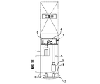
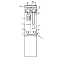
- Embodiment 1 It is a schematic diagram for demonstrating the application method of the lift extension technique of the construction elevator in Embodiment 1 (shows the case of 2: 1 roping). It is a schematic diagram for demonstrating the application method of the lift extension technique of the construction elevator in Embodiment 1 (shows the case of 2: 1 roping). It is a schematic diagram for demonstrating the application method of the lift extension technique of the construction elevator in Embodiment 1 (shows the case of 2: 1 roping). It is a schematic diagram for demonstrating the application method of the lift extension technique of the construction elevator in Embodiment 1 (shows the case of 2: 1 roping).
- FIG. 3 is a front view showing a first example of the pit unit according to the first embodiment.
- FIG. 8 is a view taken in the direction of arrows AA in FIG. 7.
- FIG. 8 is a view taken in the direction of arrows BB in FIG. 7.
- FIG. 8 is a view as viewed in the direction of arrows CC in FIG. 7.
- FIG. 3 is a front view showing a second example of the pit unit according to the first embodiment.
- FIG. 12 is a view taken along the line AA in FIG. 11.
- FIG. 12 is a view taken in the direction of arrows CC in FIG. 11.
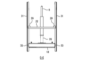
- FIG. 5 is a front view showing a third example of the pit unit according to the first embodiment.
- FIG. 15 is a view taken in the direction of arrows AA in FIG. 14.
- FIG. 15 is a view taken in the direction of arrows BB in FIG. 14.
- FIG. 15 is a view taken in the direction of the arrows CC in FIG. 14.
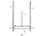
- FIG. 9 is a front view showing a fourth example of the pit unit according to the first embodiment.
- FIG. 19 is a view taken along the line AA in FIG. 18.
- FIG. 19 is a view taken along the arrow CC in FIG. 18.
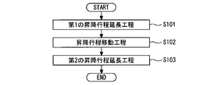
- 6 is a flowchart for explaining a procedure of a method of applying the lift extension technology of the construction elevator according to the first embodiment.
- FIG. 1 to 6 are schematic diagrams for explaining a method of applying the lift extension technology of a construction elevator according to the first embodiment. 1 to 6 illustrate the case where the roping method is 2: 1 roping, the method of applying the lift extension technology of the construction elevator is also applicable to the case where the roping method is 1: 1 roping.
- FIGS. 1 to 6 show the inside of the hoistway of a building under construction.
- the lift extension type construction elevator includes a car 1, a counterweight 2, a machine room unit 3, a temporary hoisting machine 4, a plurality of ropes 5, and a control panel 6.
- the temporary hoisting machine 4 is, for example, a small hoisting machine that does not correspond to a high stroke.
- the car 1 can be moved up and down the hoistway by being guided by a pair of car guide rails.
- the car 1 can be fixed to, for example, a car guide rail.
- the counterweight 2 can be moved up and down the hoistway by being guided by a pair of counterweight guide rails.
- the counterweight 2 can be fixed to, for example, a guide rail for the counterweight.
- the machine room unit 3 can be moved up and down the hoistway by being guided by at least one of the car guide rail and the counterweight guide rail, for example.
- the machine room unit 3 can be fixed to, for example, at least one of a car guide rail and a counterweight guide rail.
- the machine room unit 3 may be fixed to a structure on the building side under construction, for example.
- the structure is also called a building frame.
- a temporary hoisting machine 4 and a control panel 6 are mounted in the machine room unit 3.
- the plurality of ropes 5 are wound around, for example, a sheave of the temporary hoisting machine 4, a hoist of the car 1, and a hoist of the counterweight 2.
- the terminal of the rope 5 is connected to the machine room unit 3 by, for example, a shackle.
- the terminal of the rope 5 is located, for example, at the lower end of the machine room unit 3.
- the roping method is 1: 1 roping
- the hanging wheel of the car 1 and the hanging wheel of the counterweight 2 are not provided, and the terminal of the rope 5 is, for example, a shackle for the car 1 and the counterweight 2. Connected to.
- a pit unit 7 is installed.
- a car buffer 8 and a counterweight buffer 9 is mounted in the pit unit 7, for example.
- the car shock absorber 8 is located immediately below the car 1.
- the counterweight buffer 9 is located immediately below the counterweight 2.
- the pit unit 7 may be provided with, for example, a compensation sheave (not shown).
- a compensating rope that connects the lower part of the car 1 and the lower part of the counterweight 2 is wound around the compensating sheave.
- the pit unit 7 may be equipped with, for example, a car trolley (not shown).
- a car speed governor rope is wound around the car tensioner.
- the pit unit 7 may be equipped with, for example, a weight tensioner (not shown).
- a weight governor rope is wrapped around the weight tensioner.
- the pit unit 7 can be moved up and down the hoistway by being guided by at least one of a car guide rail and a counterweight guide rail, for example.
- the pit unit 7 can be fixed to, for example, at least one of a car guide rail and a counterweight guide rail.
- the pit unit 7 may be fixed to a structure on the building side under construction, for example.
- the structure is also called a building frame.
- the temporary hoisting machine 4 When the temporary hoisting machine 4 is driven in a state in which the load of the car 1 and the counterweight 2 is applied to the rope 5, the area below the machine room unit 3 and above the pit unit 7 in the building under construction is moved. The car 1 and the counterweight 2 move. This range is the current ascent / descent stroke of the car 1 and the counterweight 2.
- the temporary hoisting machine 4 is controlled by, for example, a control panel 6 mounted on the machine room unit 3. As the construction work progresses, the lifting and lowering strokes of the car 1 and the counterweight 2 are extended.
- the method of applying the lift extension technology of the construction elevator includes a first lifting stroke extension process.
- the first elevating stroke extending step the relative position of the machine room unit 3 with respect to the pit unit 7 is raised.
- the first elevating stroke extending step for example, the machine room unit 3 is lifted up using the lifting device 10 to the vicinity of the upper floor currently under construction.
- FIG. 1 exemplifies a case in which the first hoisting stroke extending step is performed in a state where the pit unit 7 is installed in a pit of a hoistway.
- the lifting device 10 used for lifting the machine room unit 3 is, for example, a tower crane or a winch.
- the lifting device 10 lifts up the machine room unit 3 with, for example, a hanging cable 11 attached to the machine room unit 3.
- FIG. 2 illustrates a case where the elevating process is extended to the maximum elevating process to which the temporary hoisting machine 4 can be applied. This maximum up-and-down stroke is described as "MAX.TR" in the figure.
- the rope 5 is exchanged for a longer one, for example, every time the up-and-down stroke is extended. Further, for example, when the rope 5 is wound around the temporary hoisting machine 4 or the like from a rope drum (not shown), the rope 5 may be unwound from the rope drum according to the extended ascending / descending stroke.
- the construction elevator can be serviced, for example, in the range from the lowest floor to the vicinity of the upper floor currently under construction.
- the method of applying the lift extension technology for construction elevators includes a lifting and lowering movement process.
- the up-and-down stroke moving process is performed in a state where the machine room unit 3 can be further moved up according to the progress of the construction.
- the machine room unit 3 and the pit unit 7 are moved in the same vertical direction.
- FIG. 3 illustrates a case where the machine room unit 3 is lifted up using the lifting device 10 in a state where the machine room unit 3 and the pit unit 7 are connected by the connecting rope 12. That is, FIG. 3 illustrates a case where the machine room unit 3 and the pit unit 7 are lifted at the same time in the up-and-down stroke moving process. In this case, even if the compensation sheave is mounted on the pit unit 7, it is not necessary to remove the compensation rope from the compensation sheave.
- the machine room unit 3 and the pit unit 7 may be individually lifted without using the connecting rope 12.
- the lifting device 10 may be used to raise the pit unit 7.
- a chain block or a winch installed in the machine room unit 3 may be used.
- a compensation sheave when a compensation sheave is mounted on the pit unit 7, in the up-and-down stroke moving process, a compensation rope is wound around the compensation sheave, and the lower part of the car 1 and the lower part of the counterweight 2 are located at the same height.
- the machine room unit 3 may be raised after the pit unit 7 is raised.
- the compensating rope will temporarily loosen, but it is not necessary to remove the compensating rope from the compensating sheave.
- the distance over which the machine room unit 3 or the pit unit 7 can be lifted by one lifting operation is limited, so that a plurality of lifting operations may be required.
- FIG. 5 As shown in FIG. Can be maintained at TR.
- the construction elevator can service the upper floors with the pit unit 7 raised as a temporary pit.
- the service of the construction elevator is not possible on the floor below the pit unit 7.
- there is no major problem because the other low-rise elevators have already started operation.
- the up-down stroke of the construction elevator can be moved upward while maintaining the maximum up-down stroke applicable to the temporary hoisting machine 4. is there.
- the method of applying the lift extension technology of the construction elevator includes a second lifting stroke extension process.
- the second ascent / descent extension process includes a main hoist installation process and a pit device installation process.
- the main hoist installation process is performed, for example, after the completion of the construction period.
- the machine room unit 3 and the temporary hoist 4 are removed, and the main hoist 14 is installed in the machine room 13, as shown in FIG.
- the pit equipment installation step for example, as shown in FIG. 6, the pit unit 7 is lowered to the lowermost part of the hoistway. In this case, the pit unit 7 is used as a pit device for permanent installation.
- the pit unit 7 used for temporary construction during the construction period may be removed, and a pit equipment for permanent construction different from the pit unit 7 may be newly installed.
- the second elevating step extension step is completed, elevator service is enabled from the lowest floor to the highest floor of the building.
- the hoisting machine 14 is, for example, a large hoisting machine corresponding to a high stroke. In a high-rise building, a machine room 13 wider than the hoistway is prepared, so that a large permanent hoisting machine 14 can be installed.
- the control panel of the hoisting machine 14 the control panel 6 mounted on the machine room unit 3 may be used, or another control panel may be used.
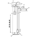
- FIG. 7 is a front view showing a first example of the pit unit according to the first embodiment.
- FIG. 8 is a view taken in the direction of arrows AA in FIG.
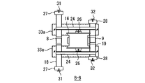
- FIG. 9 is a view taken in the direction of arrows BB in FIG.
- FIG. 10 is a view taken in the direction of arrows CC in FIG.
- front, rear, left, and right are designated with the near side in FIG. 7 as the front side and the far side in FIG. 7 as the rear side.
- the compensation sheave 15 is mounted on the first example of the pit unit 7.
- the compensation sheave 15 is provided inside the housing 16.
- a compensation rope 17 is wound around the compensation sheave 15.
- a first example of the pit unit 7 includes a car-side shock absorber stand 18, a weight-side shock absorber stand 19, a car-side shock absorber support 20, a weight-side shock absorber support 21, a car-side shock absorber support beam 22, and a weight-side shock absorber.
- the car-side shock absorber stand 18 is arranged between the pair of car guide rails 31 along the front-rear direction.
- the car-side shock absorber support 18 supports the car-side shock absorber support 20.
- the car-side shock absorber support 20 supports the car shock absorber 8.
- the car-side shock absorber support base 20 is not arranged due to the layout of the pit device, the car-side shock absorber base 18 directly supports the car shock absorber 8.
- the weight-side shock absorber base 19 is disposed between the pair of counterweight guide rails 32 along the front-rear direction.
- the weight-side shock absorber base 19 supports the weight-side shock absorber support 21.
- the weight side buffer support 21 supports the counterweight buffer 9. When the weight-side shock absorber support 21 is not arranged due to the layout of the pit device, the weight-side shock absorber support 19 directly supports the counterweight shock absorber 9.
- the car-side shock absorber support beam 22 is disposed above the car-side shock absorber base 18 along the front-rear direction.
- the car-side shock absorber support beam 22 supports the car shock absorber 8 from the left side.
- the weight side buffer support beam 23 is disposed above the weight side buffer base 19 along the front-rear direction.
- the weight side buffer support beam 23 supports the counterweight buffer 9 from the right side.
- the pair of shock absorber stand connecting beams 24 connects the upper surface of the car side shock absorber stand 18 and the upper surface of the weight side shock absorber stand 19 along the left-right direction.
- One of the shock absorber pedestal connecting beams 24 is disposed forward of the car shock absorber 8 and the counterweight shock absorber 9.
- the other shock absorber base connection beam 24 is disposed behind the car shock absorber 8 and the counterweight shock absorber 9.
- the pair of compensation sheave rail support beams 25 connects the car side buffer support beam 22 and the weight side buffer support beam 23 along the left-right direction.
- One of the compensating sheave rail support beams 25 is disposed forward of the car shock absorber 8 and the counterweight shock absorber 9.
- the other compensation sheave rail support beam 25 is disposed behind the car shock absorber 8 and the counterweight shock absorber 9.
- the pair of compensating sheave rails 26 are supported by the pair of shock absorber base connecting beams 24 and the pair of compensating sheave rail support beams 25 along the vertical direction.
- the housing 16 of the compensation sheave 15 is guided along a compensation sheave rail 26.
- a pair of car-side first guide portions 27 are provided at both ends of the car-side shock absorber base 18.
- the car-side first guide portion 27 is guided by the car guide rail 31.
- a pair of weight-side first guide portions 28 are provided at both ends of the weight-side shock absorber base 19.
- the first guide portion 28 on the weight side is guided by the guide rail 32 for counterweight.
- a pair of car-side second guide portions 29 are provided at both ends of the car-side shock absorber support beam 22.
- the car-side second guide portion 29 is guided by the car guide rail 31.
- a pair of weight-side second guide portions 30 are provided at both ends of the weight-side shock absorber support beam 23.
- the weight-side second guide portion 30 is guided by a counterweight guide rail 32.
- the pit unit 7 includes a load support device 33.
- the load support device 33 is used for fixing the pit unit 7 in the hoistway.
- the load support device 33 in the first example of the pit unit 7 includes, for example, a tubular member 33a and a slide member 33b.
- the tubular member 33a is fixed to the lower surface of the car side shock absorber stand 18 and the lower surface of the weight side shock absorber stand 19 along the left-right direction.
- the tubular member 33a is disposed, for example, below the shock absorber base connection beam 24.
- the slide member 33b is inserted into the tubular member 33a.
- the slide member 33b can be completely housed inside the tubular member 33a, for example.
- the slide member 33b can, for example, at least partially protrude from the tubular member 33a.
- the slide member 33b protruding from the tubular member 33a is supported by, for example, a landing floor 34 or a structure on the building side under construction.
- the pit unit 7 is fixed in the hoistway by supporting the load by the load support device 33.
- the load support device 33 may include, for example, a hanging tool such as an eyebolt to which the hanging cable 11 or the connecting rope 12 is connected when the pit unit 7 is lifted.
- FIG. 11 is a front view showing a second example of the pit unit according to the first embodiment.
- FIG. 12 is a view taken in the direction of the arrows AA in FIG.
- FIG. 13 is a view taken in the direction of the arrows CC in FIG.
- the compensation sheave 15 is not mounted on the second example of the pit unit 7.
- a second example of the pit unit 7 includes a car-side shock absorber support 20, a weight-side shock absorber support 21, a car-side shock absorber support beam 22, a weight-side shock absorber support beam 23, a shock absorber base connection beam 24, and a compensation sheave.
- the car shock absorber 8 is directly supported by the car side shock absorber base 18.
- the counterweight buffer 9 is directly supported by the weight-side buffer base 19.
- the structure of the load support device 33 is the same as that of the first example.
- FIG. 14 is a front view showing a third example of the pit unit according to the first embodiment.
- FIG. 15 is a view taken in the direction of arrows AA in FIG.
- FIG. 16 is a view taken in the direction of arrows BB in FIG.
- FIG. 17 is a view taken in the direction of the arrows CC in FIG.
- the structures of the car side shock absorber stand 18 and the weight side shock absorber stand 19 are different from those of the first example.
- the third example of the pit unit 7 does not include the car-side first guide 27 and the weight-side first guide 28.
- the load supporting device 33 in the third example of the pit unit 7 is provided at both ends of the car-side shock absorber stand 18 and the weight-side shock absorber stand 19.
- the pair of load supporting devices 33 provided on the car side shock absorber stand 18 are guided by the car guide rail 31.
- the pair of load supporting devices 33 provided on the weight side shock absorber base 19 are guided by the counterweight guide rail 32.
- the load support device 33 in the third example of the pit unit 7 has a function capable of being fixed to the car guide rail 31 and the counterweight guide rail 32. This function is realized by, for example, a mechanism similar to an emergency stop of an elevator.
- the pit unit 7 is fixed in the hoistway by driving the load supporting device 33. When the pit unit 7 is lifted, the fixing by the load support device 33 is released.
- the car-side shock absorber stand 18 and the weight-side shock absorber stand 19 may include, for example, a hanger such as an eyebolt to which the hanging rope 11 or the connecting rope 12 is connected when the pit unit 7 is lifted.
- FIG. 18 is a front view showing a fourth example of the pit unit in the first embodiment.
- FIG. 19 is a view taken in the direction of the arrows AA in FIG.
- FIG. 20 is a view taken in the direction of the arrows CC in FIG.
- the compensation sheave 15 is not mounted on the fourth example of the pit unit 7.
- the fourth example of the pit unit 7 includes a car-side shock absorber support 20, a weight-side shock absorber support 21, a car-side shock absorber support beam 22, a weight-side shock absorber support beam 23, a shock absorber stand connection beam 24, and a compensation sheave.
- the car shock absorber 8 is directly supported by the car side shock absorber base 18.
- the counterweight buffer 9 is directly supported by the weight-side buffer base 19.
- the structures of the car side shock absorber stand 18 and the weight side shock absorber stand 19 are the same as those of the third example.
- the function of the load support device 33 is the same as that of the third example.
- the structure of the pit unit 7 according to the first embodiment is not limited to the structure shown in FIGS.
- the pit unit 7 may be equipped with, for example, at least one of the car shock absorber 8 and the counterweight shock absorber 9.
- FIG. 21 is a flowchart for explaining a procedure of a method of applying the lift extension technology of the construction elevator according to the first embodiment.
- a procedure of a method of applying the head extension technique will be described with reference to FIG.
- step S101 the worker performs a first elevating stroke extending process.
- the first elevating stroke extending step may be repeated a plurality of times.
- step S102 the worker performs an up-and-down stroke moving process.
- the step of moving up and down may be repeated a plurality of times.
- step S103 the worker performs a step of installing a permanent hoist, a step of lowering the pit unit 7 fixed to the middle of the hoistway to the bottom of the hoistway, or a step of installing pit equipment for permanent installation.
- a second elevating stroke extending step is performed.
- the lift extension technology of the construction elevator can be applied regardless of the height of the building.
- the method of applying the lift extension technology of a construction elevator includes a first up-down stroke extension step, an up-down stroke movement step, and a second up-down stroke extension step.
- the first up-and-down stroke extension step is a step in which at least one of the car buffer unit 8 and the counterweight buffer unit 9 is mounted and the machine room unit 3 is moved relative to the pit unit 7 that can move up and down the hoistway below the machine room unit 3. This is the step of raising the position.
- the up-and-down stroke moving process is a process of moving the machine room unit 3 and the pit unit 7 in the same direction.
- the technology of extending the lift of the construction elevator using the temporary hoisting machine 4 that is smaller and lighter than the main hoisting machine 14 can be applied to high-rise buildings.
- the position of the pit unit 7 that can be moved up and down the hoistway by installing the permanent hoisting machine 14 and further mounting at least one of the car shock absorber 8 and the counterweight shock absorber 9 This is a process of lowering the pit or installing a new pit device. As a result, the restriction on the maximum height that can be serviced by the construction elevator can be eliminated.
- the machine room unit 3 is pulled up with the pit unit 7 connected to the machine room unit 3.
- the lifting operation can be performed only once, so that the operation time can be reduced.
- the pit unit 7 may be lifted after the machine room unit 3 is pulled up with the compensation rope 17 removed from the compensation sheave 15. In this case, the load in the lifting operation can be reduced. In this case, the machine room unit 3 or the pit unit 7 can be raised to a target height by a single lifting operation.
- the compensation rope 17 is wound around the compensation sheave 15 and between the lower part of the car 1 and the car buffer 8 and between the lower part of the counterweight 2 and the counterweight buffer 9.
- the machine room unit 3 may be raised after the pit unit 7 is raised in a state where the car 1 and the counterweight 2 are arranged at a position where a space is created. In this case, the load in the lifting operation can be reduced. Further, in this case, there is no need to attach / detach the compensation rope 17 to / from the compensation sheave 15.
- the machine room unit 3 or the pit unit 7 may be raised in a state where the car 1 is placed on the car shock absorber 8.
- the machine room unit 3 or the pit unit 7 may be raised in a state where the counterweight 2 is placed on the counterweight buffer 9.
- the machine room unit 3 or the pit unit 7 is placed in a state where the car 1 is mounted on the car buffer 8 and the counterweight 2 is mounted on the counterweight buffer 9. May be raised.
- the machine room unit 3 or the pit unit 7 may be raised in a state where at least one of the car 1 and the counterweight 2 is supported by the pit unit 7. In this case, the load in the lifting operation can be reduced.
- the elevating stroke is extended to the maximum elevating stroke to which the temporary hoisting machine 4 can be applied.
- the restriction on the maximum serviceable height while maintaining the movable range of the construction elevator to the maximum.
- the pit unit 7 may be assembled in advance outside the hoistway, for example.
- a step of integrally loading the pre-assembled pit unit 7 into the hoistway from the hoistway opening can be performed before the execution of the hoist stroke moving step.
- a step of taking out the pit unit 7 used for temporary use from the opening of the hoistway to carry it out of the building can be performed. As a result, the time required for installing and removing the pit unit 7 can be reduced.
- the present invention can be used for a lift-extension type elevator for high-rise buildings.
Landscapes
- Engineering & Computer Science (AREA)
- Structural Engineering (AREA)
- Civil Engineering (AREA)
- Transportation (AREA)
- Automation & Control Theory (AREA)
- Lift-Guide Devices, And Elevator Ropes And Cables (AREA)
- Types And Forms Of Lifts (AREA)
Abstract
工事用エレベーターでサービス可能な最大高さの制約を撤廃することができる工事用エレベーターの揚程延長技術の適用方法を提供することである。この発明に係る工事用エレベーターの揚程延長技術の適用方法は、かご緩衝器(8)および釣合おもり緩衝器(9)の少なくとも一方を搭載し機械室ユニット(3)の下方で昇降路を昇降可能なピットユニット(7)に対する機械室ユニット(3)の相対的な位置を上昇させる第1の昇降行程延長工程と、仮設用巻上機(4)を搭載した機械室ユニット(3)が上昇する方向にピットユニット(7)を上昇させることで建築工事の進捗に合わせて昇降行程を移動させる昇降行程移動工程と、本設用巻上機(14)を設置し、ピットユニット7の位置を下降させる、又は新設用ピット機器を設置する第2の昇降行程延長工程と、を備える。
Description
この発明は、工事用エレベーターの揚程延長技術の適用方法に関する。
揚程延長式工事用エレベーターは、かごの昇降行程が建築工事の進捗に合わせて順次延長されるエレベーターである。揚程延長式工事用エレベーターでは、巻上機を搭載した機械室ユニットを昇降路内で上昇させることで、かごの昇降行程が延長される。このようなエレベーターによれば、建築工事の作業員および資材等を効率良く運搬できる。揚程延長式工事用エレベーターとして、例えば、特許文献1に開示されたものがある。
エレベーターの昇降行程には、巻上機の能力に応じた限界値が存在する。昇降路において機械室ユニットを配置できるスペースの制約上、機械室ユニットに大型巻上機を搭載することは不可能である。このため、高層建築物において揚程延長式工事用エレベーターでサービス可能な最大高さには制約がある。
この発明は、上記の課題を解決するためになされた。その目的は、工事用エレベーターでサービス可能な最大高さの制約を撤廃することができる工事用エレベーターの揚程延長技術の適用方法を提供することである。
この発明に係る工事用エレベーターの揚程延長技術の適用方法は、揚程延長式工事用エレベーターにおいて、巻上機を搭載した機械室ユニットが上昇する方向に、かご緩衝器および釣合おもり緩衝器のうち少なくとも1つを搭載したピットユニットを上昇させることで、建築工事の進捗に合わせて昇降行程を移動させる昇降行程移動工程、を備える。
この発明によれば、昇降行程移動工程では、機械室ユニットが上昇する方向にピットユニットを上昇させる。このため、工事用エレベーターでサービス可能な最大高さの制約を撤廃することができる。
以下、添付の図面を参照して実施の形態について説明する。各図において、同一または相当する部分には同一の符号が付される。重複する説明は、適宜簡略化あるいは省略する。
実施の形態1.
図1から図6は、実施の形態1における工事用エレベーターの揚程延長技術の適用方法を説明するための模式図である。図1から図6ではローピング方式が2:1ローピングである場合を例示するが、工事用エレベーターの揚程延長技術の適用方法は、ローピング方式が1:1ローピングである場合にも適用可能である。
図1から図6は、実施の形態1における工事用エレベーターの揚程延長技術の適用方法を説明するための模式図である。図1から図6ではローピング方式が2:1ローピングである場合を例示するが、工事用エレベーターの揚程延長技術の適用方法は、ローピング方式が1:1ローピングである場合にも適用可能である。
図1から図6は、建築中の建物の昇降路内の様子を示している。例えば、図1に示すように、揚程延長式工事用エレベーターは、かご1、釣合おもり2、機械室ユニット3、仮設用巻上機4、複数のロープ5および制御盤6を備える。仮設用巻上機4は、例えば、高行程に対応しない小型巻上機である。
かご1は、一対のかご用ガイドレールに案内されて昇降路を昇降可能である。かご1は、例えば、かご用ガイドレールに対して固定可能である。釣合おもり2は、一対の釣合おもり用ガイドレールに案内されて昇降路を昇降可能である。釣合おもり2は、例えば、釣合おもり用ガイドレールに対して固定可能である。
機械室ユニット3は、例えば、かご用ガイドレールおよび釣合おもり用ガイドレールの少なくとも一方に案内されて昇降路を昇降可能である。機械室ユニット3は、例えば、かご用ガイドレールおよび釣合おもり用ガイドレールの少なくとも一方に対して固定可能である。機械室ユニット3は、例えば、建築中の建物側の構造体に固定されてもよい。当該構造体は、建築躯体とも称する。
機械室ユニット3には、例えば、仮設用巻上機4および制御盤6が搭載される。複数のロープ5は、例えば、仮設用巻上機4の綱車、かご1の吊り車および釣合おもり2の吊り車に巻き掛けられる。ロープ5の端末は、例えば、シャックルで機械室ユニット3に接続される。ロープ5の端末は、例えば、機械室ユニット3の下端部に位置する。なお、ローピング方式が1:1ローピングである場合には、かご1の吊り車および釣合おもり2の吊り車が設けられず、ロープ5の端末は、例えば、シャックルでかご1および釣合おもり2に接続される。
機械室ユニット3の下方には、ピットユニット7が設置される。ピットユニット7には、例えば、かご緩衝器8および釣合おもり緩衝器9の少なくとも一方が搭載される。かご緩衝器8は、かご1の直下に位置する。釣合おもり緩衝器9は、釣合おもり2の直下に位置する。
ピットユニット7には、例えば、図示しない補償シーブが搭載されてもよい。補償シーブには、例えば、かご1の下部と釣合おもり2の下部とを繋ぐ補償ロープが巻き掛けられる。ピットユニット7には、例えば、図示しないかご張り車が搭載されてもよい。かご張り車には、例えば、かご調速機ロープが巻き掛けられる。ピットユニット7には、例えば、図示しないおもり張り車が搭載されてもよい。おもり張り車には、例えば、おもり調速機ロープが巻き掛けられる。
ピットユニット7は、例えば、かご用ガイドレールおよび釣合おもり用ガイドレールの少なくとも一方に案内されて昇降路を昇降可能である。ピットユニット7は、例えば、かご用ガイドレールおよび釣合おもり用ガイドレールの少なくとも一方に対して固定可能である。ピットユニット7は、例えば、建築中の建物側の構造体に固定されてもよい。当該構造体は、建築躯体とも称する。
かご1および釣合おもり2の荷重がロープ5に負荷された状態で仮設用巻上機4が駆動すると、建築中の建物における機械室ユニット3よりも下方且つピットユニット7よりも上方の範囲をかご1および釣合おもり2が移動する。この範囲が、かご1および釣合おもり2の現時点での昇降行程である。仮設用巻上機4は、例えば、機械室ユニット3に搭載された制御盤6によって制御される。建築工事の進捗に合わせて、かご1および釣合おもり2の昇降行程は延長される。
以下、図1から図6を用いて、工事用エレベーターの揚程延長技術の適用方法を説明する。
工事用エレベーターの揚程延長技術の適用方法は、第1の昇降行程延長工程を含む。第1の昇降行程延長工程では、ピットユニット7に対する機械室ユニット3の相対的な位置が引き上げられる。第1の昇降行程延長工程では、例えば、現時点では工事中である上層階付近まで揚重装置10を用いて機械室ユニット3が引き上げられる。図1は、ピットユニット7が昇降路のピットに設置された状態で第1の昇降行程延長工程が行われる場合を例示する。
機械室ユニット3の引き上げに用いられる揚重装置10は、例えば、タワークレーン又はウインチ等である。揚重装置10は、例えば、機械室ユニット3に取り付けられた吊り索11で機械室ユニット3を引き上げる。
第1の昇降行程延長工程で機械室ユニット3が上昇すると、図2に示すように、昇降行程が延長される。目的の高さに到達した機械室ユニット3は、固定される。図2は、仮設用巻上機4を適用可能な最大昇降行程まで昇降行程が延長された場合を例示する。この最大昇降行程は、図中で「MAX.TR」と表記されている。
ロープ5は、例えば、昇降行程が延長されるたびに、より長いものに交換される。また、例えば、図示しないロープドラムから仮設用巻上機4等にロープ5が巻き掛けられている場合には、延長された昇降行程に応じてロープドラムからロープ5が繰り出されてもよい。
図2の状態において、工事用エレベーターは、例えば、最下階から現時点では工事中である上層階付近までの範囲でサービス可能である。
工事用エレベーターの揚程延長技術の適用方法は、昇降行程移動工程を含む。昇降行程移動工程は、工事の進捗によって機械室ユニット3が更に上昇可能となった状態で行われる。昇降行程移動工程では、機械室ユニット3およびピットユニット7が上下方向における同じ向きに移動される。
図3は、機械室ユニット3とピットユニット7とが連結ロープ12で連結された状態で、揚重装置10を用いて機械室ユニット3が引き上げられる場合を例示する。つまり、図3は、昇降行程移動工程で機械室ユニット3およびピットユニット7が同時に揚重される場合を例示する。この場合、ピットユニット7に補償シーブが搭載されていても、補償シーブから補償ロープを取り外す必要はない。
昇降行程移動工程では、例えば、連結ロープ12を用いずに、機械室ユニット3およびピットユニット7が個別に揚重されてもよい。例えば、ピットユニット7に補償シーブが搭載されていない場合、機械室ユニット3およびピットユニット7のうち一方が引き上げられた後に他方が引き上げられればよい。ピットユニット7の引き上げには、揚重装置10を用いてもよい。ピットユニット7の引き上げには、機械室ユニット3に設置されたチェーンブロック又はウインチ等を用いてもよい。
例えば、ピットユニット7に補償シーブが搭載されている場合、昇降行程移動工程では、補償シーブから補償ロープが取り外された状態で、機械室ユニット3が引き上げられた後にピットユニット7が引き上げられてもよい。この場合、一度の揚重作業で機械室ユニット3又はピットユニット7を目的の高さまで上昇させることが可能である。ただし、この場合、ピットユニット7が引き上げられた後に、補償シーブに補償ロープを掛け直す必要がある。
例えば、ピットユニット7に補償シーブが搭載されている場合、昇降行程移動工程では、補償シーブに補償ロープが巻き掛けられ且つかご1の下部と釣合おもり2の下部とが同じ高さに位置する状態で、ピットユニット7が引き上げられた後に機械室ユニット3が引き上げられてもよい。この場合、一時的に補償ロープが弛むことになるが、補償シーブから補償ロープを取り外す必要はない。ただし、この場合、一度の揚重作業で機械室ユニット3又はピットユニット7を上昇させることが可能な距離が制限されるため、複数回の揚重作業が必要となり得る。
昇降行程移動工程で機械室ユニット3およびピットユニット7が上昇すると、図4に示すように、昇降行程それ自体が上昇する。目的の高さに到達した機械室ユニット3およびピットユニット7は、それぞれ固定される。
図5に示すように、昇降行程移動工程の後も、昇降行程は、MAX.TRに維持可能である。図5の状態において、工事用エレベーターは、上昇したピットユニット7を仮設ピットとして、上層階にサービス可能である。なお、図5の状態において、ピットユニット7よりも下方の階には工事用エレベーターのサービスが不可能となる。ただし、図5に示す工事の進捗段階では、既に他の低層用エレベーターが稼働開始しているため、大きな支障はない。
図3から図5を用いて説明した昇降行程移動工程を繰り返すことで、仮設用巻上機4を適用可能な最大昇降行程を維持したまま、工事用エレベーターの昇降行程を上方向に移動可能である。
工事用エレベーターの揚程延長技術の適用方法は、第2の昇降行程延長工程を含む。第2の昇降行程延長工程は、本設用巻上機設置工程およびピット機器設置工程を含む。本設用巻上機設置工程は、例えば、工事期間終了後に行われる。本設用巻上機設置工程では、図6に示すように、機械室ユニット3および仮設用巻上機4が撤去され、機械室13に本設用巻上機14が設置される。ピット機器設置工程では、例えば、図6に示すように、ピットユニット7が昇降路最下部に降ろされる。この場合、ピットユニット7は、本設用のピット機器として用いられる。また、ピット機器設置工程では、工事期間中に仮設用として使用されたピットユニット7を撤去し、ピットユニット7とは異なる本設用のピット機器を新規に設置してもよい。第2の昇降行程延長工程が完了すると、建物の最下階から最上階までエレベーターのサービスが可能となる。
本設用巻上機14は、例えば、高行程に対応する大型巻上機である。高層建築物においては、昇降路よりも広い機械室13が用意されるため、大型の本設用巻上機14が設置可能である。本設用巻上機14の制御盤としては、機械室ユニット3に搭載されていた制御盤6を用いてもよいし、他の制御盤を用いてもよい。
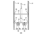
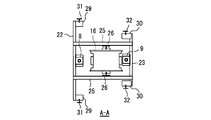
図7は、実施の形態1におけるピットユニットの第1例を示す正面図である。図8は、図7のA-A矢視図である。図9は、図7のB-B矢視図である。図10は、図7のC-C矢視図である。
以下、図7から図10を用いて、ピットユニット7の第1例の構造を説明する。この説明では、図7における手前側を前方とし、図7における奥側を後方として、前後左右を指定する。
ピットユニット7の第1例には、補償シーブ15が搭載される。補償シーブ15は、ハウジング16の内側に設けられる。補償シーブ15には、補償ロープ17が巻き掛けられる。
ピットユニット7の第1例は、かご側緩衝器台18、おもり側緩衝器台19、かご側緩衝器支持台20、おもり側緩衝器支持台21、かご側緩衝器支え梁22、おもり側緩衝器支え梁23、緩衝器台連結梁24、補償シーブ用レール支え梁25、補償シーブ用レール26、かご側第1ガイド部27、おもり側第1ガイド部28、かご側第2ガイド部29およびおもり側第2ガイド部30を備える。
かご側緩衝器台18は、前後方向に沿って、一対のかご用ガイドレール31の間に配置される。かご側緩衝器台18は、かご側緩衝器支持台20を支持する。かご側緩衝器支持台20は、かご緩衝器8を支持する。ピット機器のレイアウト性から、かご側緩衝器支持台20が配置されない場合は、かご側緩衝器台18は直接かご緩衝器8を支持する。
おもり側緩衝器台19は、前後方向に沿って、一対の釣合おもり用ガイドレール32の間に配置される。おもり側緩衝器台19は、おもり側緩衝器支持台21を支持する。おもり側緩衝器支持台21は、釣合おもり緩衝器9を支持する。ピット機器のレイアウト性から、おもり側緩衝器支持台21が配置されない場合は、おもり側緩衝器台19は直接釣合おもり緩衝器9を支持する。
かご側緩衝器支え梁22は、前後方向に沿って、かご側緩衝器台18の上方に配置される。かご側緩衝器支え梁22は、かご緩衝器8を左側から支える。
おもり側緩衝器支え梁23は、前後方向に沿って、おもり側緩衝器台19の上方に配置される。おもり側緩衝器支え梁23は、釣合おもり緩衝器9を右側から支える。
一対の緩衝器台連結梁24は、左右方向に沿って、かご側緩衝器台18の上面とおもり側緩衝器台19の上面とを連結する。一方の緩衝器台連結梁24は、かご緩衝器8および釣合おもり緩衝器9よりも前方に配置される。他方の緩衝器台連結梁24は、かご緩衝器8および釣合おもり緩衝器9よりも後方に配置される。
一対の補償シーブ用レール支え梁25は、左右方向に沿って、かご側緩衝器支え梁22とおもり側緩衝器支え梁23とを連結する。一方の補償シーブ用レール支え梁25は、かご緩衝器8および釣合おもり緩衝器9よりも前方に配置される。他方の補償シーブ用レール支え梁25は、かご緩衝器8および釣合おもり緩衝器9よりも後方に配置される。
一対の補償シーブ用レール26は、上下方向に沿って、一対の緩衝器台連結梁24および一対の補償シーブ用レール支え梁25に支持される。補償シーブ15のハウジング16は、補償シーブ用レール26に沿って案内される。
一対のかご側第1ガイド部27は、かご側緩衝器台18の両端に設けられる。かご側第1ガイド部27は、かご用ガイドレール31に案内される。
一対のおもり側第1ガイド部28は、おもり側緩衝器台19の両端に設けられる。おもり側第1ガイド部28は、釣合おもり用ガイドレール32に案内される。
一対のかご側第2ガイド部29は、かご側緩衝器支え梁22の両端に設けられる。かご側第2ガイド部29は、かご用ガイドレール31に案内される。
一対のおもり側第2ガイド部30は、おもり側緩衝器支え梁23の両端に設けられる。おもり側第2ガイド部30は、釣合おもり用ガイドレール32に案内される。
ピットユニット7は、荷重支持装置33を備える。荷重支持装置33は、ピットユニット7を昇降路内で固定するために用いられる。
ピットユニット7の第1例における荷重支持装置33は、例えば、筒状部材33aおよびスライド部材33bを備える。筒状部材33aは、左右方向に沿って、かご側緩衝器台18の下面およびおもり側緩衝器台19の下面に対して固定される。筒状部材33aは、例えば、緩衝器台連結梁24の下方に配置される。スライド部材33bは、筒状部材33aに挿入される。スライド部材33bは、例えば、筒状部材33aの内側に完全に収納可能である。スライド部材33bは、例えば、少なくとも一部分が筒状部材33aから突出可能である。
図7に示すように、筒状部材33aから突出したスライド部材33bは、例えば、乗場床34又は建築中の建物側の構造体に支持される。ピットユニット7は、荷重支持装置33によって荷重を支持されることで、昇降路内に固定される。ピットユニット7が揚重される際には、荷重支持装置33による支持が解除される。荷重支持装置33は、例えば、ピットユニット7が揚重される際に吊り索11又は連結ロープ12が接続されるアイボルト等の吊り具を備えてもよい。
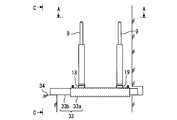
図11は、実施の形態1におけるピットユニットの第2例を示す正面図である。図12は、図11のA-A矢視図である。図13は、図11のC-C矢視図である。
以下、図11から図13を用いて、図7から図10に示す第1例との相違点を中心に、ピットユニット7の第2例の構造を説明する。
ピットユニット7の第2例には、補償シーブ15が搭載されない。ピットユニット7の第2例は、かご側緩衝器支持台20、おもり側緩衝器支持台21、かご側緩衝器支え梁22、おもり側緩衝器支え梁23、緩衝器台連結梁24、補償シーブ用レール支え梁25、補償シーブ用レール26、かご側第2ガイド部29およびおもり側第2ガイド部30を備えない。
ピットユニット7の第2例において、かご緩衝器8は、かご側緩衝器台18によって直接支持される。ピットユニット7の第2例において、釣合おもり緩衝器9は、おもり側緩衝器台19によって直接支持される。ピットユニット7の第2例において、荷重支持装置33の構造は、第1例と同様である。
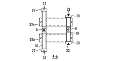
図14は、実施の形態1におけるピットユニットの第3例を示す正面図である。図15は、図14のA-A矢視図である。図16は、図14のB-B矢視図である。図17は、図14のC-C矢視図である。
以下、図14から図17を用いて、図7から図10に示す第1例との相違点を中心に、ピットユニット7の第3例の構造を説明する。
ピットユニット7の第3例において、かご側緩衝器台18およびおもり側緩衝器台19の構造は、第1例と異なる。ピットユニット7の第3例は、かご側第1ガイド部27およびおもり側第1ガイド部28を備えない。
ピットユニット7の第3例における荷重支持装置33は、かご側緩衝器台18およびおもり側緩衝器台19の両端に設けられる。かご側緩衝器台18に設けられた一対の荷重支持装置33は、かご用ガイドレール31に案内される。おもり側緩衝器台19に設けられた一対の荷重支持装置33は、釣合おもり用ガイドレール32に案内される。
ピットユニット7の第3例における荷重支持装置33は、かご用ガイドレール31および釣合おもり用ガイドレール32に対して固定可能な機能を有する。この機能は、例えば、エレベーターの非常止めと同様の機構で実現される。ピットユニット7は、荷重支持装置33が駆動することで、昇降路内に固定される。ピットユニット7が揚重される際には、荷重支持装置33による固定が解除される。かご側緩衝器台18およびおもり側緩衝器台19は、例えば、ピットユニット7が揚重される際に吊り索11又は連結ロープ12が接続されるアイボルト等の吊り具を備えてもよい。
図18は、実施の形態1におけるピットユニットの第4例を示す正面図である。図19は、図18のA-A矢視図である。図20は、図18のC-C矢視図である。
以下、図18から図20を用いて、図14から図17に示す第3例との相違点を中心に、ピットユニット7の第4例の構造を説明する。
ピットユニット7の第4例には、補償シーブ15が搭載されない。ピットユニット7の第4例は、かご側緩衝器支持台20、おもり側緩衝器支持台21、かご側緩衝器支え梁22、おもり側緩衝器支え梁23、緩衝器台連結梁24、補償シーブ用レール支え梁25、補償シーブ用レール26、かご側第1ガイド部27、おもり側第1ガイド部28、かご側第2ガイド部29およびおもり側第2ガイド部30を備えない。
ピットユニット7の第4例において、かご緩衝器8は、かご側緩衝器台18によって直接支持される。ピットユニット7の第4例において、釣合おもり緩衝器9は、おもり側緩衝器台19によって直接支持される。ピットユニット7の第4例において、かご側緩衝器台18およびおもり側緩衝器台19の構造は、第3例と同様である。ピットユニット7の第4例において、荷重支持装置33の機能は、第3例と同様である。
実施の形態1におけるピットユニット7の構造は、図7から図20に示す構造に限られない。ピットユニット7は、例えば、かご緩衝器8および釣合おもり緩衝器9のうち、少なくとも1つを搭載していればよい。
図21は、実施の形態1における工事用エレベーターの揚程延長技術の適用方法の手順を説明するためのフローチャートである。以下、図21を用いて、揚程延長技術の適用方法の手順の一例を説明する。
ステップS101では、作業員は、第1の昇降行程延長工程を行う。第1の昇降行程延長工程は、複数回繰り返されてもよい。その後、作業員は、ステップS102の工程を行う。ステップS102では、作業員は、昇降行程移動工程を行う。昇降行程移動工程は、複数回繰り返されてもよい。その後、作業員は、ステップS103の工程を行う。ステップS103では、作業員は、本設用巻上機設置工程、および昇降路中間部に固定されていたピットユニット7を昇降路最下部まで降ろす工程又は本設用のピット機器を設置する工程を行うことで、第2の昇降行程延長工程を行う。その結果、建物の高さに関係なく、工事用エレベーターの揚程延長技術を適用できる。
以上で説明した実施の形態1によれば、工事用エレベーターの揚程延長技術の適用方法は、第1の昇降行程延長工程と、昇降行程移動工程と、第2の昇降行程延長工程と、を備える。第1の昇降行程延長工程は、かご緩衝器8および釣合おもり緩衝器9の少なくとも一方を搭載し機械室ユニット3の下方で昇降路を昇降可能なピットユニット7に対する機械室ユニット3の相対的な位置を上昇させる工程である。昇降行程移動工程は、機械室ユニット3およびピットユニット7を同じ向きに移動させる工程である。このため、本設用巻上機14よりも小型且つ軽量な仮設用巻上機4を用いた工事用エレベーターの揚程延長技術を高層建築物に対しても適用可能となる。第2の昇降行程延長工程は、本設用巻上機14を設置し、さらにかご緩衝器8および釣合おもり緩衝器9の少なくとも一方を搭載して昇降路を昇降可能なピットユニット7の位置を下降させる、又は新設用ピット機器を設置する工程である。その結果、工事用エレベーターでサービス可能な最大高さの制約を撤廃することができる。
また、昇降行程移動工程では、例えば、機械室ユニット3にピットユニット7が連結された状態で機械室ユニット3が引き上げられる。この場合、揚重作業が一度で済むため、作業時間を短縮できる。
また、昇降行程移動工程では、例えば、補償シーブ15から補償ロープ17が取り外された状態で機械室ユニット3が引き上げられた後にピットユニット7が引き上げられてもよい。この場合、揚重作業における負荷を軽減できる。また、この場合、一度の揚重作業で機械室ユニット3又はピットユニット7を目的の高さまで上昇させることができる。
また、昇降行程移動工程では、例えば、補償シーブ15に補償ロープ17が巻き掛けられ且つかご1下部とかご緩衝器8との間および釣合おもり2下部と釣合おもり緩衝器9との間に空間ができる位置にかご1および釣合おもり2が配置された状態で、ピットユニット7が引き上げられた後に機械室ユニット3が引き上げられてもよい。この場合、揚重作業における負荷を軽減できる。また、この場合、補償シーブ15に補償ロープ17を着脱する必要がない。
また、昇降行程移動工程では、例えば、かご1がかご緩衝器8上に載置された状態で機械室ユニット3又はピットユニット7を上昇させてもよい。昇降行程移動工程では、例えば、釣合おもり2が釣合おもり緩衝器9上に載置された状態で機械室ユニット3又はピットユニット7を上昇させてもよい。昇降行程移動工程では、例えば、かご1がかご緩衝器8上に載置され且つ釣合おもり2が釣合おもり緩衝器9上に載置された状態で、機械室ユニット3又はピットユニット7を上昇させてもよい。つまり、昇降行程移動工程では、かご1および釣合おもり2のうち少なくとも一方の重量がピットユニット7に支持された状態で機械室ユニット3又はピットユニット7を上昇させてもよい。この場合、揚重作業における負荷を軽減できる。
また、第1の昇降行程延長工程では、例えば、仮設用巻上機4を適用可能な最大昇降行程まで昇降行程が延長される。この場合、工事用エレベーターの移動可能範囲を最大限に維持しつつ、サービス可能な最大高さの制約を撤廃することができる。
また、ピットユニット7は、例えば、予め昇降路の外部で組み立てられてもよい。この場合、昇降行程移動工程の実施前に、予め組み立てられたピットユニット7を昇降路開口部より昇降路内に一体搬入する工程を実施できる。また、この場合、昇降行程移動工程の実施後に、仮設用として使用したピットユニット7を昇降路開口部から抜き出すことで建物の外部に搬出する工程を実施できる。その結果、ピットユニット7の据付および撤去に要する時間を削減できる。
この発明は、高層建築物における揚程延長式工事用エレベーターに利用できる。
1 かご
2 釣合おもり
3 機械室ユニット
4 仮設用巻上機
5 ロープ
6 制御盤
7 ピットユニット
8 かご緩衝器
9 釣合おもり緩衝器
10 揚重装置
11 吊り索
12 連結ロープ
13 機械室
14 本設用巻上機
15 補償シーブ
16 ハウジング
17 補償ロープ
18 かご側緩衝器台
19 おもり側緩衝器台
20 かご側緩衝器支持台
21 おもり側緩衝器支持台
22 かご側緩衝器支え梁
23 おもり側緩衝器支え梁
24 緩衝器台連結梁
25 補償シーブ用レール支え梁
26 補償シーブ用レール
27 かご側第1ガイド部
28 おもり側第1ガイド部
29 かご側第2ガイド部
30 おもり側第2ガイド部
31 かご用ガイドレール
32 釣合おもり用ガイドレール
33 荷重支持装置
33a 筒状部材
33b スライド部材
34 乗場床
2 釣合おもり
3 機械室ユニット
4 仮設用巻上機
5 ロープ
6 制御盤
7 ピットユニット
8 かご緩衝器
9 釣合おもり緩衝器
10 揚重装置
11 吊り索
12 連結ロープ
13 機械室
14 本設用巻上機
15 補償シーブ
16 ハウジング
17 補償ロープ
18 かご側緩衝器台
19 おもり側緩衝器台
20 かご側緩衝器支持台
21 おもり側緩衝器支持台
22 かご側緩衝器支え梁
23 おもり側緩衝器支え梁
24 緩衝器台連結梁
25 補償シーブ用レール支え梁
26 補償シーブ用レール
27 かご側第1ガイド部
28 おもり側第1ガイド部
29 かご側第2ガイド部
30 おもり側第2ガイド部
31 かご用ガイドレール
32 釣合おもり用ガイドレール
33 荷重支持装置
33a 筒状部材
33b スライド部材
34 乗場床
Claims (11)
- 揚程延長式工事用エレベーターにおいて、巻上機を搭載した機械室ユニットが上昇する方向に、かご緩衝器および釣合おもり緩衝器のうち少なくとも1つを搭載したピットユニットを上昇させることで、建築工事の進捗に合わせて昇降行程を移動させる昇降行程移動工程、
を備えた工事用エレベーターの揚程延長技術の適用方法。 - 前記ピットユニットは、かご用ガイドレールおよび釣合おもり用ガイドレールのうち少なくとも一方に案内される構造を有した請求項1に記載の工事用エレベーターの揚程延長技術の適用方法。
- 前記ピットユニットは、かご用ガイドレール、釣合おもり用ガイドレールおよび建築躯体のうち少なくとも1つに固定可能である請求項1又は請求項2に記載の工事用エレベーターの揚程延長技術の適用方法。
- 前記昇降行程移動工程では、前記機械室ユニットを上昇させた後に前記ピットユニットを上昇させる請求項1から請求項3のいずれか1項に記載の工事用エレベーターの揚程延長技術の適用方法。
- 前記昇降行程移動工程では、かご下部とかご緩衝器との間および釣合おもり下部と釣合おもり緩衝器との間に空間ができる位置にかごおよび釣合おもりが配置された状態で、前記機械室ユニットを上昇させる前に前記ピットユニットを上昇させる請求項1から請求項3のいずれか1項に記載の工事用エレベーターの揚程延長技術の適用方法。
- 前記昇降行程移動工程では、前記機械室ユニットと前記ピットユニットとが連結された状態で両者を同時に上昇させる請求項1から請求項3のいずれか1項に記載の工事用エレベーターの揚程延長技術の適用方法。
- 前記昇降行程移動工程では、かごおよび釣合おもりのうち少なくとも一方の重量が前記ピットユニットに支持された状態で前記機械室ユニット又は前記ピットユニットを上昇させる請求項1から請求項3のいずれか1項に記載の工事用エレベーターの揚程延長技術の適用方法。
- 前記機械室ユニットは、仮設用巻上機を搭載した請求項1から請求項7のいずれか1項に記載の工事用エレベーターの揚程延長技術の適用方法。
- 前記昇降行程移動工程の実施後に、昇降路中間部に固定されていた前記ピットユニットを昇降路最下部まで下降させ、前記ピットユニットを本設用のピット機器として設置する工程、
を更に備えた請求項1から請求項8のいずれか1項に記載の工事用エレベーターの揚程延長技術の適用方法。 - 前記昇降行程移動工程の実施後に、仮設用として使用した前記ピットユニットを昇降路開口部から抜き出すことで建物の外部に搬出し、前記ピットユニットとは異なる本設用のピット機器を昇降路最下部に設置する工程、
を更に備えた請求項1から請求項8のいずれか1項に記載の工事用エレベーターの揚程延長技術の適用方法。 - 前記昇降行程移動工程の実施前に、予め昇降路の外部で組み立てられた前記ピットユニットを昇降路開口部より昇降路内に一体搬入する工程、
を更に備えた請求項1から請求項10のいずれか1項に記載の工事用エレベーターの揚程延長技術の適用方法。
Priority Applications (3)
| Application Number | Priority Date | Filing Date | Title |
|---|---|---|---|
| PCT/JP2018/030449 WO2020035933A1 (ja) | 2018-08-16 | 2018-08-16 | 工事用エレベーターの揚程延長技術の適用方法 |
| JP2020504419A JP6813123B2 (ja) | 2018-08-16 | 2018-08-16 | エレベーターの揚程延長技術の適用方法 |
| CN201880096384.8A CN112566864B (zh) | 2018-08-16 | 2018-08-16 | 电梯的扬程延长技术的应用方法 |
Applications Claiming Priority (1)
| Application Number | Priority Date | Filing Date | Title |
|---|---|---|---|
| PCT/JP2018/030449 WO2020035933A1 (ja) | 2018-08-16 | 2018-08-16 | 工事用エレベーターの揚程延長技術の適用方法 |
Publications (1)
| Publication Number | Publication Date |
|---|---|
| WO2020035933A1 true WO2020035933A1 (ja) | 2020-02-20 |
Family
ID=69525327
Family Applications (1)
| Application Number | Title | Priority Date | Filing Date |
|---|---|---|---|
| PCT/JP2018/030449 Ceased WO2020035933A1 (ja) | 2018-08-16 | 2018-08-16 | 工事用エレベーターの揚程延長技術の適用方法 |
Country Status (3)
| Country | Link |
|---|---|
| JP (1) | JP6813123B2 (ja) |
| CN (1) | CN112566864B (ja) |
| WO (1) | WO2020035933A1 (ja) |
Cited By (4)
| Publication number | Priority date | Publication date | Assignee | Title |
|---|---|---|---|---|
| US11396442B2 (en) | 2020-05-09 | 2022-07-26 | Otis Elevator Company | Low cost roped jump lift concept |
| CN115038660A (zh) * | 2020-03-16 | 2022-09-09 | 株式会社日立制作所 | 施工用升降机装置 |
| JP7167274B1 (ja) | 2021-09-03 | 2022-11-08 | 東芝エレベータ株式会社 | エレベータ装置及びその組み立て方法 |
| JP7436126B1 (ja) | 2023-06-02 | 2024-02-21 | 三菱電機ビルソリューションズ株式会社 | エレベーターのゴンドラ設置方法、及びゴンドラ装置 |
Citations (6)
| Publication number | Priority date | Publication date | Assignee | Title |
|---|---|---|---|---|
| US3759349A (en) * | 1972-03-13 | 1973-09-18 | Otis Elevator Co | Elevator system with temporary hoistway structure and method for use thereof |
| JPS5612285A (en) * | 1979-07-07 | 1981-02-06 | Fujitec Kk | Method of installing elevator with moving machine room |
| JPS5742483A (en) * | 1980-08-28 | 1982-03-10 | Fujitec Kk | Method of installation of elevator for construction |
| JPH04243788A (ja) * | 1991-01-23 | 1992-08-31 | Toshiba Corp | エレベータによる地下工事方法 |
| JP2012206857A (ja) * | 2011-03-30 | 2012-10-25 | Ohbayashi Corp | 昇降機の設置方法 |
| US20120291395A1 (en) * | 2009-12-31 | 2012-11-22 | Kone Corporation | Method in the manufacture of an elevator |
Family Cites Families (4)
| Publication number | Priority date | Publication date | Assignee | Title |
|---|---|---|---|---|
| JP3214325B2 (ja) * | 1995-12-18 | 2001-10-02 | 三菱電機株式会社 | エレベーターの据付工法 |
| JP2839872B2 (ja) * | 1996-07-29 | 1998-12-16 | 株式会社サノヤス・ヒシノ明昌 | 立坑用ロープ式エレベータ |
| FI114458B (fi) * | 2002-12-02 | 2004-10-29 | Kone Corp | Menetelmä ja laitteisto hissin asentamiseksi rakennuksen rakentamisvaiheessa |
| CN204958044U (zh) * | 2015-09-18 | 2016-01-13 | 西子西奥电梯有限公司 | 无底坑轿厢架和无底坑别墅电梯 |
-
2018
- 2018-08-16 WO PCT/JP2018/030449 patent/WO2020035933A1/ja not_active Ceased
- 2018-08-16 JP JP2020504419A patent/JP6813123B2/ja active Active
- 2018-08-16 CN CN201880096384.8A patent/CN112566864B/zh active Active
Patent Citations (6)
| Publication number | Priority date | Publication date | Assignee | Title |
|---|---|---|---|---|
| US3759349A (en) * | 1972-03-13 | 1973-09-18 | Otis Elevator Co | Elevator system with temporary hoistway structure and method for use thereof |
| JPS5612285A (en) * | 1979-07-07 | 1981-02-06 | Fujitec Kk | Method of installing elevator with moving machine room |
| JPS5742483A (en) * | 1980-08-28 | 1982-03-10 | Fujitec Kk | Method of installation of elevator for construction |
| JPH04243788A (ja) * | 1991-01-23 | 1992-08-31 | Toshiba Corp | エレベータによる地下工事方法 |
| US20120291395A1 (en) * | 2009-12-31 | 2012-11-22 | Kone Corporation | Method in the manufacture of an elevator |
| JP2012206857A (ja) * | 2011-03-30 | 2012-10-25 | Ohbayashi Corp | 昇降機の設置方法 |
Cited By (5)
| Publication number | Priority date | Publication date | Assignee | Title |
|---|---|---|---|---|
| CN115038660A (zh) * | 2020-03-16 | 2022-09-09 | 株式会社日立制作所 | 施工用升降机装置 |
| US11396442B2 (en) | 2020-05-09 | 2022-07-26 | Otis Elevator Company | Low cost roped jump lift concept |
| JP7167274B1 (ja) | 2021-09-03 | 2022-11-08 | 東芝エレベータ株式会社 | エレベータ装置及びその組み立て方法 |
| JP2023037484A (ja) * | 2021-09-03 | 2023-03-15 | 東芝エレベータ株式会社 | エレベータ装置及びその組み立て方法 |
| JP7436126B1 (ja) | 2023-06-02 | 2024-02-21 | 三菱電機ビルソリューションズ株式会社 | エレベーターのゴンドラ設置方法、及びゴンドラ装置 |
Also Published As
| Publication number | Publication date |
|---|---|
| CN112566864B (zh) | 2022-04-15 |
| CN112566864A (zh) | 2021-03-26 |
| JP6813123B2 (ja) | 2021-01-13 |
| JPWO2020035933A1 (ja) | 2020-08-27 |
Similar Documents
| Publication | Publication Date | Title |
|---|---|---|
| CN104066670B (zh) | 方法和电梯配置 | |
| JP5264751B2 (ja) | エレベータの揚重装置及びエレベータの揚重方法 | |
| CN105026298B (zh) | 电梯的改造方法 | |
| CN115038660B (zh) | 施工用升降机装置 | |
| JP6813123B2 (ja) | エレベーターの揚程延長技術の適用方法 | |
| JP6969686B2 (ja) | 工事用エレベーターの揚程延長方法 | |
| CN110191855B (zh) | 电梯的安装方法 | |
| WO2020044444A1 (ja) | 揚程延長式工事用エレベーター | |
| JP7559261B2 (ja) | 工事用エレベーター及び工事用エレベーターのコンペンロープの延長方法 | |
| JP2003276970A (ja) | エレベーター装置 | |
| JP2008285260A (ja) | 機械室レスエレベータのガイドレール据え付け工法 | |
| JP2022150841A (ja) | エレベータのリニューアル方法およびエレベータ | |
| JP2013245033A (ja) | 巻上機据付方法 | |
| JP5930842B2 (ja) | エレベータの据付方法及び据付用治具 | |
| JP4312590B2 (ja) | エレベータ上部機器の下部組立て工法 | |
| JPH0480188A (ja) | ダブルデッキエレベータ | |
| JP7436126B1 (ja) | エレベーターのゴンドラ設置方法、及びゴンドラ装置 | |
| JP7804747B1 (ja) | エレベータの昇降路揚重装置および昇降路揚重方法 | |
| JP2016008131A (ja) | エレベーター及び既設エレベーターの改造方法 | |
| JPH04129981A (ja) | 油圧エレベータの据付工法 | |
| JP2011020803A (ja) | エレベータのリニューアル方法 | |
| JP7404506B2 (ja) | 工事用エレベーター装置及びエレベーターの主索延長方法 | |
| JP3301948B2 (ja) | エレベータの据付工法 | |
| JP2011042493A (ja) | エレベータ設備 | |
| JP2025030182A (ja) | エレベータレールの揚重システム、および、揚重方法 |
Legal Events
| Date | Code | Title | Description |
|---|---|---|---|
| ENP | Entry into the national phase |
Ref document number: 2020504419 Country of ref document: JP Kind code of ref document: A |
|
| 121 | Ep: the epo has been informed by wipo that ep was designated in this application |
Ref document number: 18929943 Country of ref document: EP Kind code of ref document: A1 |
|
| NENP | Non-entry into the national phase |
Ref country code: DE |
|
| 122 | Ep: pct application non-entry in european phase |
Ref document number: 18929943 Country of ref document: EP Kind code of ref document: A1 |