WO2020035928A1 - 空気調和機のインターフェイス - Google Patents
空気調和機のインターフェイス Download PDFInfo
- Publication number
- WO2020035928A1 WO2020035928A1 PCT/JP2018/030431 JP2018030431W WO2020035928A1 WO 2020035928 A1 WO2020035928 A1 WO 2020035928A1 JP 2018030431 W JP2018030431 W JP 2018030431W WO 2020035928 A1 WO2020035928 A1 WO 2020035928A1
- Authority
- WO
- WIPO (PCT)
- Prior art keywords
- air conditioner
- interface
- mode
- control unit
- external device
- Prior art date
- Legal status (The legal status is an assumption and is not a legal conclusion. Google has not performed a legal analysis and makes no representation as to the accuracy of the status listed.)
- Ceased
Links
Images




Classifications
-
- F—MECHANICAL ENGINEERING; LIGHTING; HEATING; WEAPONS; BLASTING
- F24—HEATING; RANGES; VENTILATING
- F24F—AIR-CONDITIONING; AIR-HUMIDIFICATION; VENTILATION; USE OF AIR CURRENTS FOR SCREENING
- F24F11/00—Control or safety arrangements
- F24F11/88—Electrical aspects, e.g. circuits
-
- F—MECHANICAL ENGINEERING; LIGHTING; HEATING; WEAPONS; BLASTING
- F24—HEATING; RANGES; VENTILATING
- F24F—AIR-CONDITIONING; AIR-HUMIDIFICATION; VENTILATION; USE OF AIR CURRENTS FOR SCREENING
- F24F11/00—Control or safety arrangements
- F24F11/50—Control or safety arrangements characterised by user interfaces or communication
-
- F—MECHANICAL ENGINEERING; LIGHTING; HEATING; WEAPONS; BLASTING
- F24—HEATING; RANGES; VENTILATING
- F24F—AIR-CONDITIONING; AIR-HUMIDIFICATION; VENTILATION; USE OF AIR CURRENTS FOR SCREENING
- F24F11/00—Control or safety arrangements
- F24F11/50—Control or safety arrangements characterised by user interfaces or communication
- F24F11/52—Indication arrangements, e.g. displays
-
- F—MECHANICAL ENGINEERING; LIGHTING; HEATING; WEAPONS; BLASTING
- F24—HEATING; RANGES; VENTILATING
- F24F—AIR-CONDITIONING; AIR-HUMIDIFICATION; VENTILATION; USE OF AIR CURRENTS FOR SCREENING
- F24F11/00—Control or safety arrangements
- F24F11/50—Control or safety arrangements characterised by user interfaces or communication
- F24F11/56—Remote control
-
- F—MECHANICAL ENGINEERING; LIGHTING; HEATING; WEAPONS; BLASTING
- F24—HEATING; RANGES; VENTILATING
- F24F—AIR-CONDITIONING; AIR-HUMIDIFICATION; VENTILATION; USE OF AIR CURRENTS FOR SCREENING
- F24F11/00—Control or safety arrangements
- F24F11/62—Control or safety arrangements characterised by the type of control or by internal processing, e.g. using fuzzy logic, adaptive control or estimation of values
- F24F11/63—Electronic processing
- F24F11/65—Electronic processing for selecting an operating mode
-
- F—MECHANICAL ENGINEERING; LIGHTING; HEATING; WEAPONS; BLASTING
- F24—HEATING; RANGES; VENTILATING
- F24F—AIR-CONDITIONING; AIR-HUMIDIFICATION; VENTILATION; USE OF AIR CURRENTS FOR SCREENING
- F24F11/00—Control or safety arrangements
- F24F11/62—Control or safety arrangements characterised by the type of control or by internal processing, e.g. using fuzzy logic, adaptive control or estimation of values
- F24F11/63—Electronic processing
- F24F11/65—Electronic processing for selecting an operating mode
- F24F11/67—Switching between heating and cooling modes
-
- F—MECHANICAL ENGINEERING; LIGHTING; HEATING; WEAPONS; BLASTING
- F24—HEATING; RANGES; VENTILATING
- F24F—AIR-CONDITIONING; AIR-HUMIDIFICATION; VENTILATION; USE OF AIR CURRENTS FOR SCREENING
- F24F2110/00—Control inputs relating to air properties
- F24F2110/10—Temperature
Definitions
- the present invention relates to an interface of an air conditioner that controls the operation of an air conditioner and the operation of an external device having a function of performing air conditioning.
- Patent Literature 1 discloses a technique of operating an air conditioner and floor heating in an interlocked manner.
- the present invention has been made in view of the above, and even if both an air conditioner and an external device having a function of performing air conditioning have no means capable of directly communicating with the other party, the air An object of the present invention is to obtain an interface of an air conditioner that realizes an interlocking operation between the conditioner and an external device.
- an interface of an air conditioner includes an air conditioner, an operation terminal used by a user to operate the air conditioner, and a function of performing air conditioning.
- the control unit controls the operation of the air conditioner and the operation of the external device in accordance with one of the operation modes set in the operation mode.
- the interface of the air conditioner according to the present invention allows the air conditioner to be connected to the external device even if both the air conditioner and the external device having the function of performing air conditioning have no means capable of directly communicating with the other party. There is an effect that an interlocking operation with the device can be realized.
- FIG. 1 shows an example of the operation of the air-conditioning system when the operation mode set in the interface of the air conditioner according to the embodiment corresponds to the first special operation.
- FIG. 2 shows an example of the operation of the air-conditioning system when the operation mode set in the interface of the air conditioner according to the embodiment corresponds to the first special operation.
- FIG. 3 shows an example of the operation of the air conditioning system when the operation mode set in the interface of the air conditioner according to the embodiment corresponds to the first special operation.
- FIG. 5 is a flowchart showing a procedure of a first operation of the interface of the air conditioner according to the embodiment.
- corresponds to a 2nd special operation.
- the figure which shows the processor in case at least one part function of the control part, the air conditioner communication part, the data conversion part, the operation terminal communication part, and the display part which the interface of the air conditioner which concerns on embodiment has is realized by a processor.
- FIG. 1 is a diagram illustrating a configuration of an interface 1 of the air conditioner according to the embodiment.
- interface 1 of the air conditioner may be referred to as “interface 1”.
- the air conditioner 2 and the operation terminal 3 are connected to the interface 1.
- FIG. 1 also shows an air conditioner 2 and an operation terminal 3.
- the operation terminal 3 is a device used by a user to operate the air conditioner 2.
- a relay 4 is connected to the interface 1.
- An external device 5 having a function of performing air conditioning is connected to the relay 4.
- FIG. 1 also shows the relay 4 and the external device 5.
- An external device 5 is also connected to the interface 1 via a relay 4.
- An example of the external device 5 is a heater. In the following, it is assumed that the external device 5 is a heater.
- the interface 1 has a control unit 6 for controlling operations of the air conditioner 2 and the external device 5.
- the control unit 6 includes a first operation mode in which the air conditioner 2 operates alone and a second operation mode in which the air conditioner 2 and the external device 5 can operate simultaneously.
- the operation of the air conditioner 2 and the operation of the external device 5 are controlled according to one of the set operation modes.
- the first operation mode or the second operation mode is set for the interface 1.
- the control unit 6 controls the operation target device between the air conditioner 2 and the external device 5 according to the air conditioning operation mode instructed from the operation terminal 3. Determine and operate the determined operation target device.
- the control unit 6 determines, based on the relationship between the room temperature, which is the temperature inside the room where the air conditioner 2 is installed, and the set temperature when the operation mode is the automatic mode.
- the operation mode is determined to be one of the cooling mode and the heating mode, and the operation target device is determined according to the determined mode.
- the set temperature is set in the interface 1 by the operation terminal 3.
- the interface 1 further includes an air conditioner communication unit 7 that communicates with the air conditioner 2.
- the air conditioner communication unit 7 receives information from the air conditioner 2.
- the interface 1 further includes a data conversion unit 8 that converts information received by the air conditioner communication unit 7 into information corresponding to the automatic mode when the air conditioner 2 is a device that does not support the automatic mode.
- the interface 1 further includes an operation terminal communication unit 9 that communicates with the operation terminal 3. Under the control of the control unit 6, the operation terminal communication unit 9 transmits the information obtained by the data conversion unit 8 to the operation terminal 3.
- the interface 1 further includes a display unit 10 for displaying a communication state between the interface 1, the air conditioner 2, and the operation terminal 3.
- An example of the display unit 10 is a light emitting diode.
- the interface 1 further includes a group of dip switches 11 to which the first operation mode or the second operation mode is given by a user.
- the interface 1 further includes a storage unit 12 that stores information indicating an operation mode given by a user between the first operation mode and the second operation mode.
- the storage unit 12 also stores information indicating the set temperature set by the operation terminal 3.
- An example of the storage unit 12 is an EEPROM (registered trademark) (Electrically Erasable Programmable Read Only Memory).
- the control unit 6 has a function of controlling the air conditioner communication unit 7, the data conversion unit 8, the operation terminal communication unit 9, the display unit 10, and the storage unit 12.
- the control unit 6 has a function of inputting / outputting data to / from each of the air conditioner communication unit 7, the data conversion unit 8, the operation terminal communication unit 9, the display unit 10, and the storage unit 12.
- the control unit 6 has a function of acquiring information indicating the operation mode given to the DIP switch group 11 from the DIP switch group 11.
- the air conditioner communication unit 7, the data conversion unit 8, the operation terminal communication unit 9, the display unit 10, the DIP switch group 11, and the storage unit 12 are connected to the control unit 6.
- the control unit 6 reads information indicating the operation mode given to the DIP switch group 11 from the DIP switch group 11 when the interface 1 is activated.
- the start of the interface 1 is when the power is turned on to the interface 1.
- the control unit 6 operates based on the read information.
- FIG. 2 is a diagram for explaining operation modes given to the dip switch group 11 included in the interface 1 of the air conditioner according to the embodiment. It is assumed that the DIP switch group 11 has a first DIP switch and a second DIP switch. Each of the first dip switch and the second dip switch takes one of an on state and an off state. In the example of FIG. 2, when both the first dip switch and the second dip switch are in an off state, a normal operation for operating the air conditioner 2 alone is set as the operation mode. Normal operation corresponds to the first operation mode. In normal operation, the operation target device is the air conditioner 2.
- the air conditioner 2 has a function of performing cooling, drying, blowing, and heating.
- the operation mode allows the air conditioner 2 and the external device 5 to be operated simultaneously.
- the first special operation corresponds to one example of the second operation mode.
- the operation target devices are the air conditioner 2 and the external device 5.
- the air conditioner 2 performs cooling, drying, and blowing, and the external device 5 performs heating.
- the operation mode allows the air conditioner 2 and the external device 5 to be operated simultaneously.
- the second special operation corresponds to another example of the second operation mode.
- the operation target devices are the air conditioner 2 and the external device 5.
- the air conditioner 2 performs cooling, drying, blowing, and heating, and the external device 5 performs heating.
- One of the first operation mode in which the air conditioner 2 is operated independently and the second operation mode in which the air conditioner 2 and the external device 5 can be operated at the same time are the dip modes. It does not have to be provided to the switch group 11. Any one of the first operation mode and the second operation mode may be given to the operation terminal 3 by a user. In this case, the operation terminal 3 transmits information indicating the operation mode given by the user between the first operation mode and the second operation mode to the interface 1, and the operation terminal communication unit 9 receives the information and performs control. The unit 6 stores the information received by the operation terminal communication unit 9 in the storage unit 12. In that case, the control unit 6 reads the information stored in the storage unit 12.
- the control unit 6 When the interface 1 is restarted by, for example, resetting the power supply, the control unit 6 reads the information indicating the operation mode given to the DIP switch group 11 before the reset or reads the information stored in the storage unit 12. Judge what it is. When reading the information given to the DIP switch group 11 before the reset, the control unit 6 reads the information given to the DIP switch group 11 after the reset. If the control unit 6 has read the instruction stored in the storage unit 12 before the reset, the control unit 6 reads the information stored in the storage unit 12 after the reset. Thereby, the operation of the interface 1 returns to the operation before the reset.
- the operation terminal 3 may discard the operation mode given to the operation terminal 3 and follow the operation mode given to the dip switch group 11.
- the control unit 6 has a function of setting the operation specified by the operation terminal 3 to the air conditioner 2 via the data conversion unit 8 and the air conditioner communication unit 7.
- the room temperature which is the temperature inside the room where the air conditioner 2 is installed, is measured by the air conditioner 2.
- the operation terminal 3 also measures the room temperature.
- the dip switch group 11 is also provided with an instruction indicating whether to acquire information indicating the room temperature from the air conditioner 2 or the operation terminal 3.
- the control unit 6 acquires information indicating the room temperature from the air conditioner 2 or the operation terminal 3 according to the instruction given to the dip switch group 11.
- the fan of the air conditioner 2 does not rotate. May measure temperature. Therefore, when the air conditioner 2 is stopped during heating as in the first special operation, the device that measures the indoor temperature may be switched from the air conditioner 2 to the operation terminal 3.
- the external device 5 operates when connected to the interface 1 via the relay 4. However, the external device 5 may operate when both the interface 1 and the external device 5 have wireless devices, and information is shared between the interface 1 and the external device 5 by wireless. In that case, the interface 1 and the external device 5 may operate based on information transmitted from the operation terminal 3.
- the above wireless device is a device having a function of performing wireless communication by Wi-Fi (registered trademark) or Bluetooth (registered trademark).
- FIG. 3 is a flowchart illustrating an example of a procedure of an operation of the interface 1 of the air conditioner according to the embodiment.
- the control unit 6 reads information indicating the setting given to the DIP switch group 11 when the interface 1 is activated (S1).
- the setting includes an operation mode.
- the control unit 6 determines the operation mode indicated by the read information (S2).
- the control unit 6 controls the normal operation (S3), and the operation mode corresponds to the first special operation.
- the first special operation is controlled (S4), and when it is determined that the operation mode corresponds to the second special operation, the second special operation is controlled (S5).
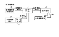
- FIG. 4 is a first diagram illustrating an example of the operation of the air-conditioning system when the operation mode set in the interface 1 of the air conditioner according to the embodiment corresponds to the first special operation.
- the air conditioning system includes an interface 1, an air conditioner 2, an operation terminal 3, a relay 4, and an external device 5. It is assumed that the air conditioner 2, the operation terminal 3, and the relay 4 are connected to the interface 1.
- the operation terminal 3 transmits an instruction to start the cooling operation to the interface 1.
- the instruction transmitted from the operation terminal 3 to the interface 1 is described as “cooling operation”.
- the interface 1 transmits an instruction to start the cooling operation to the air conditioner 2.
- the instruction transmitted by the interface 1 to the air conditioner 2 is described as “cooling operation”.
- Interface 1 does not output any instructions to relay 4.
- the air conditioner 2 performs the cooling operation according to the instruction transmitted from the interface 1. Since the interface 1 does not output any instruction to the relay 4, the relay 4 is opened and the interface 1 and the external device 5 are not connected. The external device 5 stops.
- the air conditioning system When the user 30 performs an operation to start the dry operation or the blowing operation on the operation terminal 3, the air conditioning system performs the same operation as the operation when the user 30 performs the operation to start the cooling operation on the operation terminal 3. I do. However, the cooling operation is replaced with a dry operation or a blowing operation.
- FIG. 5 is a second diagram illustrating an example of the operation of the air-conditioning system when the operation mode set in the interface 1 of the air conditioner according to the embodiment corresponds to the first special operation.
- the operation terminal 3 transmits an instruction to start the heating operation to the interface 1.
- the instruction transmitted from the operation terminal 3 to the interface 1 is described as “heating operation”.
- the interface 1 sends an instruction to stop to the air conditioner 2.
- the interface 1 outputs an instruction to start the heating operation to the relay 4 when the room temperature is equal to or lower than the set temperature.
- the set temperature is set in the interface 1 by the operation terminal 3.
- the relay 4 closes according to an instruction to start the heating operation, thereby connecting the interface 1 and the external device 5.
- the external device 5 performs a heating operation.
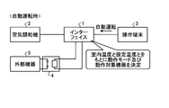
- FIG. 6 is a third diagram showing an example of the operation of the air-conditioning system when the operation mode set in the interface 1 of the air conditioner according to the embodiment corresponds to the first special operation.
- the operation terminal 3 transmits an instruction to start automatic driving to the interface 1.
- the instruction transmitted from the operation terminal 3 to the interface 1 is described as “automatic driving”.
- the interface 1 acquires information indicating the room temperature from the air conditioner 2 or the operation terminal 3 and compares the room temperature with the set temperature set by the operation terminal 3.
- the interface 1 determines an operation mode and an operation target device according to the comparison result, and performs an operation when starting a cooling operation or a heating operation. When one or both of the room temperature and the set temperature are changed, the interface 1 performs an operation according to the change.
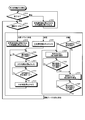
- FIG. 7 is a flowchart showing a procedure of a first operation of the interface 1 of the air conditioner according to the embodiment. Specifically, FIG. 7 shows a procedure of the operation of the interface 1 in the first special operation.
- the control unit 6 of the interface 1 confirms an instruction indicating whether to operate the operation target device (S11). For example, the instruction is transmitted from the operation terminal 3 to the interface 1.
- the control unit 6 stops both the air conditioner 2 and the external device 5 (S12). After performing the operation of step S12, the control unit 6 performs the operation of step S11 again.
- the control unit 6 When the control unit 6 confirms that the instruction is an instruction to operate the operation target device (operation in S11), the control unit 6 confirms the operation mode (S13). For example, information indicating the driving mode is transmitted from the operation terminal 3 to the interface 1.
- the control unit 6 confirms that the operation mode is the cooling / dry / blowing mode (cooling / dry / blowing in S13)
- the control unit 6 causes the air conditioner 2 to perform the cooling operation, the dry operation or the blowing operation, and the external device 5 Is stopped (S14).
- the cooling / dry / blowing mode is one of a cooling mode, a dry mode, and a blowing mode.
- control unit 6 When the control unit 6 confirms that the operation mode is the heating mode (heating in S13), the control unit 6 stops the air conditioner 2 (S15). The control unit 6 determines whether the room temperature, which is the temperature inside the room where the air conditioner 2 is installed, is equal to or lower than a set temperature (S16). When determining that the room temperature is higher than the set temperature (No in S16), the control unit 6 performs the operation of step S16 again.
- the controller 4 determines whether or not the room temperature is equal to or higher than a temperature obtained by adding ⁇ degrees to the set temperature (S18). ⁇ is a positive value.
- the temperature obtained by adding ⁇ degrees to the set temperature is referred to as “set temperature + ⁇ ”.
- the control unit 6 When determining that the room temperature is equal to or higher than the set temperature + ⁇ (Yes in S18), the control unit 6 opens the relay 4 and stops the external device 5 (S19). After performing the operation of step S19, the control unit 6 performs the operation of step S16.
- the control unit 6 determines whether or not the room temperature is equal to or higher than the set temperature (S20). When determining that the room temperature is equal to or higher than the set temperature (Yes in S20), the control unit 6 performs the same control as in the cooling mode (S21). When determining that the room temperature is lower than the set temperature (No in S20), the control unit 6 performs the same control as in the heating mode (S22).
- step S21 the control unit 6 determines whether or not the state in which the room temperature is lower than the set temperature has continued for three minutes (S23). When the control unit 6 determines that the state in which the room temperature is lower than the set temperature has continued for three minutes (Yes in S23), the control unit 6 performs the operation of step S21. When determining that the state in which the room temperature is lower than the set temperature is not continuous for three minutes (No in S23), the control unit 6 performs the operation of Step S23 again.
- step S24 the control unit 6 determines whether or not the state in which the room temperature is equal to or higher than the set temperature has continued for three minutes (S24).
- the controller 6 determines that the state in which the room temperature is equal to or higher than the set temperature has continued for three minutes (Yes in S24)
- the controller 6 performs the operation of step S23.
- the control unit 6 performs the operation of step S24 again.
- control unit 6 receives an instruction to change the operation mode from the operation terminal 3 when the operation is being performed in any of the plurality of operation modes, the control unit 6 performs the operation of step S13 again.
- the instruction to change the operation mode is expressed by the phrase “change in operation mode has occurred”.
- the control unit 6 determines that the room temperature is equal to or lower than the set temperature (Yes in S16), the control unit 6 operates the external device 5 (S17). ). That is, the operating condition of the external device 5 is a condition that the room temperature is equal to or lower than the set temperature.
- the operating condition of the external device 5 is not limited to the condition that the room temperature is equal to or lower than the set temperature, and may be set by an instruction from the operation terminal 3.
- the control unit 6 determines whether or not the room temperature is equal to or higher than the set temperature in step S20, and according to the determination result, the cooling mode or the heating mode.
- the same control as in the mode is performed (S21, S22). That is, the condition under which the control unit 6 performs the same control as in the cooling mode is a condition that the room temperature is equal to or higher than the set temperature.
- the condition under which the control unit 6 performs the same control as in the cooling mode is not limited to the condition that the room temperature is equal to or higher than the set temperature. It may be set.
- the time of “3 minutes” in the driving mode is an example, and may be changed according to an instruction from the operation terminal 3.
- the air conditioner 2 in the above description with reference to FIG. 7 does not have a function of performing a heating operation, and may be a device having a function of performing operations of cooling, drying, and blowing, or may perform only an operation of cooling. It may be a device having a function to perform.
- the air conditioner communication unit 7 of the interface 1 receives the model information of the air conditioner 2 from the air conditioner 2.
- the data conversion unit 8 of the interface 1 changes the model information to model information including information indicating that the air conditioner 2 supports the automatic mode. I do.
- the operation terminal communication unit 9 of the interface 1 transmits the changed model information to the operation terminal 3.
- the operation terminal 3 configures an operation screen based on the model information of the air conditioner 2 transmitted from the interface 1.
- the interface 1 sends the model information including information indicating that the air conditioner 2 supports the automatic mode to the operation terminal 3. Send. Therefore, even if the air conditioner 2 does not support the automatic mode, the operation terminal 3 switches the operation mode from the cooling / dry / blowing mode or the heating mode to the automatic mode for the interface 1. be able to.
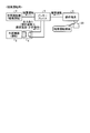
- FIG. 8 is a diagram illustrating an example of the operation of the air-conditioning system when the operation mode set in the interface 1 of the air conditioner according to the embodiment corresponds to the second special operation.
- the operation terminal 3 transmits an instruction to start the heating operation to the interface 1.
- the instruction transmitted from the operation terminal 3 to the interface 1 is described as “heating operation”.
- the interface 1 transmits an instruction to start the heating operation to the air conditioner 2.
- the instruction transmitted by the interface 1 to the air conditioner 2 is described as “heating operation”.
- the air conditioner 2 performs a heating operation.
- the interface 1 outputs an instruction to start the heating operation to the relay 4.
- the relay 4 closes according to an instruction to start the heating operation, thereby connecting the interface 1 and the external device 5.
- the external device 5 performs a heating operation.
- FIG. 9 is a flowchart illustrating a procedure of a second operation of the interface 1 of the air conditioner according to the embodiment. Specifically, FIG. 9 shows a procedure of the operation of the interface 1 in the second special operation.
- the control unit 6 of the interface 1 confirms an instruction indicating whether or not to operate the operation target device (S31).
- the control unit 6 stops both the air conditioner 2 and the external device 5 (S32). After performing the operation in step S32, the control unit 6 performs the operation in step S31 again.
- control unit 6 When the control unit 6 confirms that the instruction is an instruction to operate the operation target device (operation in S31), the control unit 6 confirms the operation mode (S33). If the control unit 6 confirms that the operation mode is the cooling / dry / blowing mode (cooling / dry / blowing in S33), the control unit 6 causes the air conditioner 2 to perform the cooling operation, the dry operation or the blowing operation, and the external device 5 Is stopped (S34).
- the control unit 6 When the control unit 6 confirms that the operation mode is the heating mode (heating in S43), the control unit 6 causes the air conditioner 2 to perform the heating operation (S35). The control unit 6 determines whether or not the room temperature is equal to or lower than a temperature obtained by subtracting ⁇ degrees from the set temperature (S36). ⁇ is a positive value. Hereinafter, a temperature obtained by subtracting ⁇ degrees from the set temperature is referred to as “set temperature ⁇ ”. When determining that the room temperature is higher than the set temperature ⁇ (No in S36), the control unit 6 performs the operation of step S36 again. When the control unit 6 determines that the room temperature is equal to or lower than the set temperature ⁇ (Yes in S36), the control unit 6 operates the external device 5 (S37).
- the control unit 6 determines whether or not the room temperature is equal to or higher than the set temperature (S38). When determining that the room temperature is lower than the set temperature (No in S38), the control unit 6 performs the operation of step S38 again. When determining that the room temperature is equal to or higher than the set temperature (Yes in S38), the controller 6 opens the relay 4 and stops the external device 5 (S39). When performing the operation of step S39, the control unit 6 causes the air conditioner 2 to perform the heating operation. After performing the operation of Step S39, the control unit 6 performs the operation of Step S36.
- the control unit 6 waits for a result of determining whether the air conditioner 2 performs the same operation as the automatic cooling or the automatic heating ( S40).
- the air conditioner communication unit 7 of the interface 1 receives data indicating that automatic cooling or automatic heating is to be performed from the air conditioner 2, and the control unit 6 operates according to the data received by the air conditioner communication unit 7. The same operation as when the operation mode is the cooling mode or the heating mode is performed (S41).
- control unit 6 When the control unit 6 receives an instruction to change the operation mode from the operation terminal 3 when the operation is being performed in any of the plurality of operation modes, the control unit 6 performs the operation of step S33 again.
- the instruction to change the operation mode is represented by the phrase “operation mode change occurred”.
- the interface 1 operates based on the operation mode given to the DIP switch group 11 or the operation mode indicated by the information transmitted from the operation terminal 3 to the interface 1. And the operation of the external device 5. That is, the interface 1 realizes the interlocking operation between the air conditioner 2 and the external device 5 even if both the air conditioner 2 and the external device 5 do not have a unit capable of directly communicating with the other party. be able to.
- the interface 1 operates according to the above-described operation mode and operation mode. That is, the interface 1 drives the operation target device according to the operation mode and the operation mode. Even if each of the air conditioner 2, the operation terminal 3, and the external device 5 is not changed from the existing one, the interface 1 operates the air conditioner 2 and the external device 5 according to the operation mode and the operation mode. And the stop, and the operation of the air conditioner 2 and the operation of the external device 5 can be linked.
- the control unit 6 operates the air conditioner 2 and the external device 5 according to the operation mode instructed from the operation terminal 3. Is determined, and the determined operation target device is operated. Therefore, the interface 1 can be used for controlling the operation of the external device 5 using the operation terminal 3 used by the user to operate the air conditioner 2.
- the control unit 6 determines the relationship between the room temperature, which is the temperature inside the room where the air conditioner 2 is installed, and the set temperature. , The operation mode is determined to be one of the cooling mode and the heating mode, and the operation target device is determined according to the determined mode. Therefore, the interface 1 can suppress an increase in the number of times the user operates the air conditioner 2.
- the interface 1 causes both the air conditioner 2 and the external device 5 to perform the heating operation, and adjusts the room temperature in a shorter time than when only the air conditioner 2 performs the heating operation. Can be higher.
- the operation mode shown in FIG. 2 is one example.
- the external device 5 is assumed to be a heater, but the external device 5 may be a device other than the heater.
- the external device 5 may be an air purifier, a dehumidifier, or a humidifier.
- a plurality of external devices 5 may be connected to the interface 1.
- some or all of the air purifier, the dehumidifier, and the humidifier may be connected to the interface 1 together with the air conditioner 2 and the external device 5, in which case the interface 1 is connected to the air conditioner 2 and the air purifier. May be operated simultaneously.
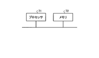
- FIG. 10 is a block diagram showing the control unit 6, the air conditioner communication unit 7, the data conversion unit 8, the operation terminal communication unit 9, and the display unit 10 of the interface 1 of the air conditioner according to the embodiment.
- FIG. 3 is a diagram illustrating a processor 71 realized by the processor 71; That is, at least a part of the functions of the control unit 6, the air conditioner communication unit 7, the data conversion unit 8, the operation terminal communication unit 9, and the display unit 10 is realized by the processor 71 executing a program stored in the memory 72. You may.
- the processor 71 is a CPU (Central Processing Unit), a processing device, an arithmetic device, a microprocessor, or a DSP (Digital Signal Processor).
- FIG. 10 also shows the memory 72.
- the processor 71 When at least some of the functions of the control unit 6, the air conditioner communication unit 7, the data conversion unit 8, the operation terminal communication unit 9, and the display unit 10 are realized by the processor 71, the at least some of the functions are performed by the processor 71. And software, firmware, or a combination of software and firmware. Software or firmware is described as a program and stored in the memory 72. The processor 71 reads out and executes the program stored in the memory 72, thereby executing at least a part of the functions of the control unit 6, the air conditioner communication unit 7, the data conversion unit 8, the operation terminal communication unit 9, and the display unit 10. To achieve.
- the interface 1 includes the control unit 6, It has a memory 72 for storing a program in which steps executed by at least a part of the air conditioner communication unit 7, the data conversion unit 8, the operation terminal communication unit 9, and the display unit 10 are executed as a result. .
- the program stored in the memory 72 causes the computer to execute a procedure or a method executed by at least a part of the control unit 6, the air conditioner communication unit 7, the data conversion unit 8, the operation terminal communication unit 9, and the display unit 10. It can be said that
- the memory 72 is, for example, a nonvolatile or volatile semiconductor memory such as a RAM (Random Access Memory), a ROM (Read Only Memory), a flash memory, an EPROM (Erasable Programmable Read Only Memory), an EEPROM (registered trademark), or a magnetic disk. , A flexible disk, an optical disk, a compact disk, a mini disk or a DVD (Digital Versatile Disk).
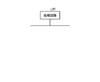
- FIG. 11 shows that the control unit 6, the air conditioner communication unit 7, the data conversion unit 8, the operation terminal communication unit 9, and the display unit 10 of the interface 1 of the air conditioner according to the embodiment include a processing circuit 81.
- FIG. 3 is a diagram showing a processing circuit 81 realized by the above. That is, at least a part of the control unit 6, the air conditioner communication unit 7, the data conversion unit 8, the operation terminal communication unit 9, and the display unit 10 may be realized by the processing circuit 81.
- the processing circuit 81 is dedicated hardware.
- the processing circuit 81 is, for example, a single circuit, a composite circuit, a programmed processor, a parallel programmed processor, an ASIC (Application Specific Integrated Circuit), an FPGA (Field-Programmable Gate Array), or a combination thereof. It is.
- At least a part of the control unit 6, the air conditioner communication unit 7, the data conversion unit 8, the operation terminal communication unit 9, and the display unit 10 may be dedicated hardware separate from the rest.
- the air conditioner communication unit 7, the data conversion unit 8, the operation terminal communication unit 9, and the display unit 10 some of the plurality of functions are realized by software or firmware, and the plurality of functions are implemented. May be realized by dedicated hardware. As described above, the plurality of functions of the control unit 6, the air conditioner communication unit 7, the data conversion unit 8, the operation terminal communication unit 9, and the display unit 10 are realized by hardware, software, firmware, or a combination thereof. Can be.
Landscapes
- Engineering & Computer Science (AREA)
- Chemical & Material Sciences (AREA)
- Combustion & Propulsion (AREA)
- Mechanical Engineering (AREA)
- General Engineering & Computer Science (AREA)
- Signal Processing (AREA)
- Human Computer Interaction (AREA)
- Physics & Mathematics (AREA)
- Fuzzy Systems (AREA)
- Mathematical Physics (AREA)
- Air Conditioning Control Device (AREA)
- Selective Calling Equipment (AREA)
Abstract
Description
図1は、実施の形態に係る空気調和機のインターフェイス1の構成を示す図である。以下では、「空気調和機のインターフェイス1」を「インターフェイス1」と記載する場合がある。インターフェイス1には、空気調和機2及び操作端末3が接続される。図1には、空気調和機2及び操作端末3も示されている。操作端末3は、ユーザが空気調和機2を操作するために用いる装置である。インターフェイス1には、リレー4が接続されている。リレー4には、空気調和を行う機能を有する外部機器5が接続されている。図1には、リレー4及び外部機器5も示されている。インターフェイス1には、リレー4を介して外部機器5も接続される。外部機器5の例は、ヒータである。以下では、外部機器5はヒータであることを想定する。
Claims (4)
- 空気調和機と、ユーザが前記空気調和機を操作するために用いる操作端末と、空気調和を行う機能を有する外部機器とが接続される空気調和機のインターフェイスであって、
前記空気調和機を単独で動作させる第1動作モードと、前記空気調和機と前記外部機器とを同時に動作させることを可能とする第2動作モードとのうちの設定されたいずれかの動作モードにしたがって、前記空気調和機の動作と前記外部機器の動作とを制御する制御部
を備える空気調和機のインターフェイス。 - 前記第2動作モードが設定されている場合、前記制御部は、前記操作端末から指示された空気調和の運転モードにしたがって、前記空気調和機と前記外部機器とのうちの動作対象機器を決定し、決定した前記動作対象機器を動作させる
請求項1に記載の空気調和機のインターフェイス。 - 前記制御部は、前記動作対象機器を決定する場合、前記運転モードが自動モードであるとき、前記空気調和機が設置されている室の内部の温度である室内温度と設定温度との関係をもとに、前記運転モードを冷房モードと暖房モードとのうちのいずれか一方に決定し、決定したモードにしたがって前記動作対象機器を決定する
請求項2に記載の空気調和機のインターフェイス。 - 前記空気調和機から情報を受信する空気調和機通信部と、
前記空気調和機が前記自動モードに対応しない機器である場合に前記空気調和機通信部によって受信された前記情報を前記自動モードに対応する情報に変換するデータ変換部と、
前記データ変換部によって得られた前記情報を前記操作端末に送信する操作端末通信部と
を更に備える請求項3に記載の空気調和機のインターフェイス。
Priority Applications (4)
| Application Number | Priority Date | Filing Date | Title |
|---|---|---|---|
| JP2020537334A JP6949235B2 (ja) | 2018-08-16 | 2018-08-16 | 空気調和機のインターフェイス |
| PCT/JP2018/030431 WO2020035928A1 (ja) | 2018-08-16 | 2018-08-16 | 空気調和機のインターフェイス |
| CA3100917A CA3100917C (en) | 2018-08-16 | 2018-08-16 | Air conditioner interface |
| US17/051,601 US11391485B2 (en) | 2018-08-16 | 2018-08-16 | Air conditioner interface |
Applications Claiming Priority (1)
| Application Number | Priority Date | Filing Date | Title |
|---|---|---|---|
| PCT/JP2018/030431 WO2020035928A1 (ja) | 2018-08-16 | 2018-08-16 | 空気調和機のインターフェイス |
Publications (1)
| Publication Number | Publication Date |
|---|---|
| WO2020035928A1 true WO2020035928A1 (ja) | 2020-02-20 |
Family
ID=69525305
Family Applications (1)
| Application Number | Title | Priority Date | Filing Date |
|---|---|---|---|
| PCT/JP2018/030431 Ceased WO2020035928A1 (ja) | 2018-08-16 | 2018-08-16 | 空気調和機のインターフェイス |
Country Status (4)
| Country | Link |
|---|---|
| US (1) | US11391485B2 (ja) |
| JP (1) | JP6949235B2 (ja) |
| CA (1) | CA3100917C (ja) |
| WO (1) | WO2020035928A1 (ja) |
Citations (10)
| Publication number | Priority date | Publication date | Assignee | Title |
|---|---|---|---|---|
| JPH09196441A (ja) * | 1996-01-24 | 1997-07-31 | Sanyo Electric Co Ltd | 空気調和装置 |
| JPH11173633A (ja) * | 1997-12-09 | 1999-07-02 | Sanyo Electric Co Ltd | 暖房システム |
| JP2001108285A (ja) * | 1999-10-08 | 2001-04-20 | Sanyo Electric Co Ltd | 暖房システム |
| JP2008082586A (ja) * | 2006-09-26 | 2008-04-10 | Matsushita Electric Works Ltd | 床暖房装置とエアコンの連動運転システム |
| JP2011127860A (ja) * | 2009-12-21 | 2011-06-30 | Toho Gas Co Ltd | 暖房システム |
| JP2013170789A (ja) * | 2012-02-22 | 2013-09-02 | Toho Gas Co Ltd | 暖房システム |
| JP2013194924A (ja) * | 2012-03-15 | 2013-09-30 | Toho Gas Co Ltd | 空調システム |
| JP2017166708A (ja) * | 2016-03-14 | 2017-09-21 | 日立マクセル株式会社 | 空調制御システム |
| JP2017166754A (ja) * | 2016-03-16 | 2017-09-21 | シャープ株式会社 | 空気調和機および空気調和機の制御方法 |
| JP2018071950A (ja) * | 2016-11-04 | 2018-05-10 | シャープ株式会社 | 空気調和機、ネットワークシステム、サーバ、および情報処理方法 |
Family Cites Families (15)
| Publication number | Priority date | Publication date | Assignee | Title |
|---|---|---|---|---|
| JP3157447B2 (ja) | 1996-01-24 | 2001-04-16 | 三洋電機株式会社 | 空気調和装置 |
| US7802618B2 (en) * | 2005-01-19 | 2010-09-28 | Tim Simon, Inc. | Thermostat operation method and apparatus |
| US7664575B2 (en) * | 2007-08-15 | 2010-02-16 | Trane International Inc. | Contingency mode operating method for air conditioning system |
| US8112181B2 (en) * | 2008-10-11 | 2012-02-07 | Ralph Remsburg | Automatic mold and fungus growth inhibition system and method |
| US8774947B2 (en) * | 2011-03-28 | 2014-07-08 | Emerson Electric Co. | Controller for a climate control system |
| JP5881466B2 (ja) * | 2012-02-28 | 2016-03-09 | 三菱電機株式会社 | 空調用リモートコントローラ及び空気調和システム |
| US9551501B2 (en) * | 2013-03-15 | 2017-01-24 | Honeywell International Inc. | Multi-mode auto changeover system |
| JP6253675B2 (ja) * | 2014-01-27 | 2017-12-27 | 日立ジョンソンコントロールズ空調株式会社 | 空調機試運転アプリケーション、及び空調機試運転システム |
| US9784461B2 (en) * | 2014-08-26 | 2017-10-10 | Haier US Applicance Solutions, Inc. | Air conditioner heater control based on power supply cord parameters |
| JP6751896B2 (ja) | 2016-05-19 | 2020-09-09 | パナソニックIpマネジメント株式会社 | 機器制御方法 |
| US10088192B2 (en) * | 2016-10-06 | 2018-10-02 | Google Llc | Thermostat algorithms and architecture for efficient operation at low temperatures |
| US11384951B2 (en) * | 2017-06-14 | 2022-07-12 | Joseph A. Ross | Zoning system for air conditioning (HVAC) equipment |
| US20180363933A1 (en) * | 2017-06-14 | 2018-12-20 | Joseph A. Ross | Zoning System for Air Conditioning (HVAC) Equipment |
| US11920812B2 (en) * | 2018-05-16 | 2024-03-05 | Mitsubishi Electric Corporation | Air conditioning system |
| CN109114759B (zh) * | 2018-10-15 | 2020-05-22 | 广东美的制冷设备有限公司 | 控制终端、一拖多空调器的控制方法及装置和存储介质 |
-
2018
- 2018-08-16 JP JP2020537334A patent/JP6949235B2/ja active Active
- 2018-08-16 CA CA3100917A patent/CA3100917C/en active Active
- 2018-08-16 WO PCT/JP2018/030431 patent/WO2020035928A1/ja not_active Ceased
- 2018-08-16 US US17/051,601 patent/US11391485B2/en active Active
Patent Citations (10)
| Publication number | Priority date | Publication date | Assignee | Title |
|---|---|---|---|---|
| JPH09196441A (ja) * | 1996-01-24 | 1997-07-31 | Sanyo Electric Co Ltd | 空気調和装置 |
| JPH11173633A (ja) * | 1997-12-09 | 1999-07-02 | Sanyo Electric Co Ltd | 暖房システム |
| JP2001108285A (ja) * | 1999-10-08 | 2001-04-20 | Sanyo Electric Co Ltd | 暖房システム |
| JP2008082586A (ja) * | 2006-09-26 | 2008-04-10 | Matsushita Electric Works Ltd | 床暖房装置とエアコンの連動運転システム |
| JP2011127860A (ja) * | 2009-12-21 | 2011-06-30 | Toho Gas Co Ltd | 暖房システム |
| JP2013170789A (ja) * | 2012-02-22 | 2013-09-02 | Toho Gas Co Ltd | 暖房システム |
| JP2013194924A (ja) * | 2012-03-15 | 2013-09-30 | Toho Gas Co Ltd | 空調システム |
| JP2017166708A (ja) * | 2016-03-14 | 2017-09-21 | 日立マクセル株式会社 | 空調制御システム |
| JP2017166754A (ja) * | 2016-03-16 | 2017-09-21 | シャープ株式会社 | 空気調和機および空気調和機の制御方法 |
| JP2018071950A (ja) * | 2016-11-04 | 2018-05-10 | シャープ株式会社 | 空気調和機、ネットワークシステム、サーバ、および情報処理方法 |
Also Published As
| Publication number | Publication date |
|---|---|
| CA3100917A1 (en) | 2020-02-20 |
| CA3100917C (en) | 2023-01-24 |
| US20210239349A1 (en) | 2021-08-05 |
| JP6949235B2 (ja) | 2021-10-13 |
| US11391485B2 (en) | 2022-07-19 |
| JPWO2020035928A1 (ja) | 2021-01-07 |
Similar Documents
| Publication | Publication Date | Title |
|---|---|---|
| ES2986567T3 (es) | Sistema de control de aparato y procedimiento de control de aparato | |
| US20180320918A1 (en) | Air-conditioner remote controller and air-conditioning control system | |
| JP6298323B2 (ja) | 温度環境制御システムおよび装置 | |
| US11920812B2 (en) | Air conditioning system | |
| JPWO2020250347A1 (ja) | 空調制御装置および空調制御システム | |
| JPWO2020148864A1 (ja) | 空気調和制御システム | |
| JPWO2019064616A1 (ja) | ネットワークシステム | |
| US11874004B2 (en) | Ventilation control device and ventilation system | |
| WO2018002990A1 (ja) | 空気調和機 | |
| JP7377333B2 (ja) | 空気調和機 | |
| TWI679384B (zh) | 空氣清淨機以及網路系統 | |
| JP2015152201A (ja) | 窓開閉システム | |
| WO2020035928A1 (ja) | 空気調和機のインターフェイス | |
| CN107270481B (zh) | 送风装置的控制方法及相关设备 | |
| JPWO2019030896A1 (ja) | プログラム更新方法、室外機及び管理装置 | |
| WO2019058570A1 (ja) | サーバ、情報処理方法、ネットワークシステム、および空気清浄機 | |
| JP7079791B2 (ja) | サーバおよび電気機器 | |
| WO2020158615A1 (ja) | 空気調和システム | |
| JP2013029275A (ja) | 制御装置および制御システム | |
| JP5657289B2 (ja) | コントローラ、換気システム、制御方法、およびプログラム | |
| JP5470457B2 (ja) | 空調システム | |
| JP7819001B2 (ja) | 制御システム、機器制御方法およびプログラム | |
| US10883737B2 (en) | Ventilation control device | |
| WO2019171487A1 (ja) | 換気装置および遠隔操作装置 | |
| KR100683827B1 (ko) | 공기조화기의 제어 방법 |
Legal Events
| Date | Code | Title | Description |
|---|---|---|---|
| 121 | Ep: the epo has been informed by wipo that ep was designated in this application |
Ref document number: 18930495 Country of ref document: EP Kind code of ref document: A1 |
|
| ENP | Entry into the national phase |
Ref document number: 2020537334 Country of ref document: JP Kind code of ref document: A |
|
| ENP | Entry into the national phase |
Ref document number: 3100917 Country of ref document: CA |
|
| NENP | Non-entry into the national phase |
Ref country code: DE |
|
| 122 | Ep: pct application non-entry in european phase |
Ref document number: 18930495 Country of ref document: EP Kind code of ref document: A1 |