WO2020031965A1 - イオン発生装置、支持部材、および、装着部 - Google Patents
イオン発生装置、支持部材、および、装着部 Download PDFInfo
- Publication number
- WO2020031965A1 WO2020031965A1 PCT/JP2019/030742 JP2019030742W WO2020031965A1 WO 2020031965 A1 WO2020031965 A1 WO 2020031965A1 JP 2019030742 W JP2019030742 W JP 2019030742W WO 2020031965 A1 WO2020031965 A1 WO 2020031965A1
- Authority
- WO
- WIPO (PCT)
- Prior art keywords
- air
- support member
- air passage
- wall surface
- ion generator
- Prior art date
- Legal status (The legal status is an assumption and is not a legal conclusion. Google has not performed a legal analysis and makes no representation as to the accuracy of the status listed.)
- Ceased
Links
Images






Classifications
-
- F—MECHANICAL ENGINEERING; LIGHTING; HEATING; WEAPONS; BLASTING
- F24—HEATING; RANGES; VENTILATING
- F24F—AIR-CONDITIONING; AIR-HUMIDIFICATION; VENTILATION; USE OF AIR CURRENTS FOR SCREENING
- F24F7/00—Ventilation
- F24F7/003—Ventilation in combination with air cleaning
-
- A—HUMAN NECESSITIES
- A61—MEDICAL OR VETERINARY SCIENCE; HYGIENE
- A61L—METHODS OR APPARATUS FOR STERILISING MATERIALS OR OBJECTS IN GENERAL; DISINFECTION, STERILISATION OR DEODORISATION OF AIR; CHEMICAL ASPECTS OF BANDAGES, DRESSINGS, ABSORBENT PADS OR SURGICAL ARTICLES; MATERIALS FOR BANDAGES, DRESSINGS, ABSORBENT PADS OR SURGICAL ARTICLES
- A61L9/00—Disinfection, sterilisation or deodorisation of air
- A61L9/16—Disinfection, sterilisation or deodorisation of air using physical phenomena
- A61L9/22—Ionisation
-
- H—ELECTRICITY
- H01—ELECTRIC ELEMENTS
- H01T—SPARK GAPS; OVERVOLTAGE ARRESTERS USING SPARK GAPS; SPARKING PLUGS; CORONA DEVICES; GENERATING IONS TO BE INTRODUCED INTO NON-ENCLOSED GASES
- H01T23/00—Apparatus for generating ions to be introduced into non-enclosed gases, e.g. into the atmosphere
Definitions
- the present invention relates to an ion generator, a support member, and a mounting unit.
- Ion generators that supply ions to indoor air are widely used.
- various techniques for efficiently supplying ions to indoor air in an ion generator have been disclosed.
- the ion generator described in Patent Literature 1 includes a blowing mechanism, a duct, and an electrode block.
- the blower sends out air toward the duct.
- the duct constitutes a flow path through which the air sent by the blowing mechanism flows.
- the duct has an opening in a side wall.
- the electrode block is configured to be detachable from the duct.
- the electrode block has an ion generator.
- the ion generating section has a needle-shaped discharge electrode to which a positive voltage or a negative voltage is applied, and an induction electrode facing the discharge electrode. In a state where the electrode block is mounted on the duct, the following state occurs. That is, the ion generator is inserted into the opening, and the discharge electrode and the induction electrode are positioned so as to face each other in the flow path. The opening is closed by the electrode block.
- the ion generator described in Patent Literature 1 since the electrode block is configured to be detachable from the duct, the ion generator can be replaced when the ion generator deteriorates. However, the ion generator has room for improvement in increasing the amount of ions contained in air.
- the present invention has been made in view of the above problems, and has as its object to provide an ion generator, a support member, and a mounting portion capable of increasing the amount of ions contained in air.
- the ion generator includes a discharger, an air passage, a support member, and a mounting member.
- the ion generator generates a discharge factor.
- the air passage sends air containing the discharge factor to the outside of the ion generator.
- the support member detachably supports the discharger such that the discharger protrudes toward the center of the air passage.
- the mounting member is configured such that the support member is detachable in a first direction.
- the mounting member is arranged along a wall surface of the air passage.
- the first direction indicates a direction that is substantially orthogonal to the air delivery direction and that is parallel to the wall surface of the air passage.
- the discharge factor includes at least one of a positive ion and a negative ion.
- the support member according to the present invention supports a discharger that generates a discharge factor.
- the support member detachably supports the discharger such that the discharger protrudes toward the center of the air passage.
- the air passage sends out air containing the discharge factor to the outside of the air passage.
- the discharge factor includes at least one of a positive ion and a negative ion.
- the mounting portion according to the present invention is configured such that the support member is detachable in the first direction.
- the support member supports a discharger that generates a discharge factor.
- the mounting part is arranged along a wall surface of the air passage.
- the air passage sends out air containing the discharge factor to the outside of the air passage.
- the first direction indicates a direction that is substantially orthogonal to the air delivery direction and that is parallel to the wall surface of the air passage.
- the discharge factor includes at least one of a positive ion and a negative ion.
- the amount of ions contained in air can be increased.
- composition of the back side of the ion generating part concerning the embodiment of the present invention. It is a perspective view showing an example of composition of a support member concerning an embodiment of the present invention. It is a perspective view showing an example of composition of an ion generator concerning an embodiment of the present invention.
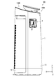
- FIG. 1 is a side view showing an example of the configuration of the air cleaning device 100.
- the air cleaning device 100 includes a first unit 100A and a second unit 100B.
- the air cleaning device 100 corresponds to an example of an “ion generator”.
- an X axis, a Y axis, and a Z axis orthogonal to each other are shown in the drawings.
- the Z axis is parallel to the vertical direction
- the X axis and Y axis are parallel to the horizontal direction.
- the positive direction of the X axis indicates the front side of the air cleaning device 100.
- the first unit 100A is arranged on the negative side of the X-axis of the air cleaning device 100. That is, the first unit 100 ⁇ / b> A is disposed on the back side of the air cleaning device 100.
- the second unit 100B is arranged on the X-axis positive direction side of the air cleaning device 100. That is, the second unit 100 ⁇ / b> B is arranged on the front side of the air cleaning device 100.
- the air purification device 100 includes the housing 1.
- the housing 1 has a main housing 11 and a front cover 12.
- the main housing 11 covers a rear surface of the air cleaning device 100 and a part of a side surface of the air cleaning device 100.
- the front cover 12 covers the front surface of the air cleaning device 100 and another part of the side surface of the air cleaning device 100.
- the front cover 12 is configured to be detachable from the main housing 11.
- the second unit 100B has a filter.
- the filter has a deodorizing filter, a formaldehyde adsorption filter, and a dust collecting filter.
- Each of the deodorizing filter, formaldehyde adsorption filter and dust collecting filter is formed in a flat plate shape.
- the deodorizing filter, formaldehyde adsorption filter, and dust collecting filter are stacked in the X-axis direction in order from the front side.
- the deodorizing filter deodorizes air.
- the formaldehyde adsorption filter adsorbs formaldehyde in the air.
- the dust collection filter adsorbs dust in the air.
- the main housing 11 has a side cover 111.
- the side cover 111 covers the mounting portion.
- the mounting unit is configured such that the ion generating unit is detachable.
- the ion generator generates ions.
- the mounting section will be described in detail with reference to FIGS.
- FIG. 2 is a side view showing an example of the configuration of the mounting section 3.
- the first unit 100A includes a mounting unit 3.
- the mounting section 3 has an opening 31.
- An ion generator is inserted into the opening 31. Specifically, the ion generator is inserted into the opening 31 in the positive direction of the Y axis, and the ion generator is mounted on the mounting unit 3.
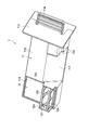
- FIG. 3 is a front view showing an example of the configuration of the first unit 100A.
- FIG. 4 is a perspective view showing an example of the configuration of the first unit 100A.
- the first unit 100 ⁇ / b> A includes a motor 4, a fan 5, a flow path forming member 6, and an ion generating section 7 in addition to the mounting section 3.
- the motor 4 drives the fan 5 to rotate.
- the motor 4 is arranged below the first unit 100A.
- the fan 5 generates a flow of air.
- the fan 5 is arranged below the first unit 100A. Specifically, the fan 5 discharges air from the discharge port 64 to the outside of the air cleaning device 100 via the flow path forming member 6 as shown in the direction D.
- the direction D indicates the direction of the air flow.
- the flow path forming member 6 includes a duct 60, a first wall member 61, a second wall member 62, a third wall member 63, and a discharge port 64.
- the flow path forming member 6 guides the air discharged by the fan 5 toward the discharge port 64 via the duct 60.
- the duct 60 causes the air discharged by the fan 5 to flow toward the outlet 64.
- the duct 60 is arranged above the fan 5.
- the duct 60 corresponds to an example of a “blowing path”.
- the first wall member 61, the second wall member 62, and the third wall member 63 form a duct 60.
- the first wall member 61 forms a wall of the duct 60 on the negative side of the X axis.
- the first wall member 61 is formed parallel to the YZ plane.
- the second wall member 62 forms a wall on the negative side of the Y axis in the duct 60.
- the second wall member 62 is erected on the first wall member 61.
- the second wall member 62 is formed parallel to the XZ plane.
- the third wall member 63 forms a wall of the duct 60 on the Y axis positive direction side.
- the third wall member 63 is erected on the first wall member 61.
- the third wall member 63 is formed parallel to the XZ plane.
- a fourth wall member (not shown) is arranged on the duct 60 in the positive X-axis direction.
- the fourth wall member is fixed to an end of the second wall member 62 on the positive side in the X-axis direction and an end of the third wall member 63 on the positive side in the X-axis direction.
- the fourth wall member forms a wall of the duct 60 on the X axis positive direction side.
- the fourth wall member is formed parallel to the XZ plane.
- the discharge port 64 is formed on the upper part of the air cleaning device 100.
- the discharge port 64 discharges the air discharged by the fan 5 to the outside of the air cleaning device 100.
- the ion generator 7 is configured to be detachable from the mounting unit 3 in the first direction DR1.
- the first direction DR1 is substantially orthogonal to the direction D.
- the first direction DR1 indicates a direction parallel to the Y axis.
- the mounting part 3 is fixed to the first wall member 61 of the duct 60.
- the ion generator 7 includes a support member 71 and an ion generator 72.
- the support member 71 supports the ion generator 72 detachably. Specifically, the support member 71 supports the ion generator 72 so that the ion generator 72 protrudes toward the center of the duct 60.
- the “central part of the duct 60” indicates the central part of the duct 60 in the X-axis direction and the central part of the duct 60 in the Y-axis direction. The support member 71 will be described later in detail with reference to FIGS.
- the ion generator 72 includes a first electrode 721 and a second electrode 722.
- the first electrode 721 and the second electrode 722 are arranged in a first direction DR1. Specifically, the first electrode 721 is arranged on the positive side of the Y axis, and the second electrode 722 is arranged on the negative side of the Y axis.
- the first electrode 721 generates, for example, positive ions.
- the second electrode 722 generates, for example, negative ions.
- the ion generator 72 will be described later in detail with reference to FIG.
- the ion generator 72 corresponds to an example of a “discharger”.
- the mounting portion 3 is arranged along the wall surface of the first wall member 61 of the duct 60.
- the mounting section 3 further includes a first inclined member 32.
- the first inclined member 32 is arranged on the upstream side in the direction D with respect to the support member 71.
- the width W1 of the first inclined member 32 in the first direction DR1 is smaller than the width W2 and the width W3 of the first wall member 61 in the first direction DR1.
- the width W1 indicates the width of the first inclined member 32 in the first direction DR1.
- the width W2 indicates the width of the first wall member 61 in the first direction DR1 at the upstream end of the first inclined member 32 in the direction D.
- the width W3 indicates the width of the first wall member 61 in the first direction DR1 at the downstream end of the first inclined member 32 in the direction D.
- the wall surface of the first wall member 61 corresponds to an example of “the wall surface of the air passage on which the first inclined member is disposed”.
- Each of the width W2 and the width W3 of the first wall member 61 in the first direction DR1 matches the distance between the second wall member 62 and the third wall member 63.
- the first inclined member 32 will be further described later with reference to FIG.
- the fan 5 draws in air from outside the air cleaning device 100 as shown by a direction D.
- the air sucked from the outside flows into the fan 5 via the filter arranged in the second unit 100B.
- the air discharged by the fan 5 is discharged to the outside of the air cleaning device 100 from the discharge port 64 via the duct 60 as shown in the direction D.
- the support member 71 is configured to be detachable from the mounting unit 3.
- the mounting section 3 is arranged along the wall surface of the duct 60 (the wall surface of the first wall member 61). Accordingly, it is possible to suppress each of the support member 71 and the mounting portion 3 from obstructing the flow of air in the duct 60. Therefore, the amount of ions contained in the air can be increased.
- the first electrode 721 and the second electrode 722 are arranged in the first direction DR1. Therefore, air containing positive ions and air containing negative ions are sent out of the air cleaning device 100. Therefore, the amount of ions contained in the air can be further increased.
- the width W1 of the first inclined member 32 in the first direction DR1 is smaller than the width W2 and the width W3 of the first wall member 61 in the first direction DR1. Therefore, it is possible to suppress the first inclined member 32 from obstructing the flow of the air in the duct 60. Therefore, the amount of ions contained in the air can be further increased.
- the mounting portion 3 is arranged along the wall surface of the first wall member 61 of the duct 60, but the present invention is not limited to this. It is sufficient that the mounting section 3 is arranged along the wall surface of the duct 60.
- the mounting portion 3 may be arranged along the wall surface of the second wall member 62 of the duct 60.
- the ion generator 72 generates positive ions and negative ions, but the ion generator 72 only needs to generate a discharge factor.
- the discharge factor includes at least one of a positive ion and a negative ion. That is, the ion generator 72 may generate at least one of a positive ion and a negative ion.
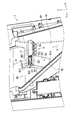
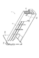
- FIGS. 5 and 6 are perspective views showing an example of the configuration of the ion generator 7 and the mounting unit 3. 6 differs from the ion generator 7 shown in FIG. 5 in that the ion generator 7 is drawn in the negative direction of the Y axis.
- the ion generator 7 is configured to be detachable from the mounting unit 3 in the first direction DR1.
- the first direction DR1 indicates a direction parallel to the Y axis.
- the ion generator 7 is removed from the mounting unit 3 by moving the ion generator 7 in the negative direction of the Y axis.
- the ion generator 7 is mounted on the mounting unit 3 by moving the ion generator 7 in the positive direction of the Y axis.
- the tip of the ion generator 7 (supporting member 71) is inserted into the opening 31 shown in FIG. 2, and the ion generator 7 is moved in the positive direction of the Y-axis. Is mounted on the mounting section 3.
- the tip of the ion generator 7 is the end on the side where the first electrode 721 is arranged in the longitudinal direction of the ion generator 7.
- the longitudinal direction of the ion generator 7 indicates a direction parallel to the Y axis.
- the first inclined member 32 of the mounting part 3 is formed in a triangular prism shape.
- the first inclined member 32 is formed integrally with the first wall member 61.
- the wall surface of the first wall member 61 corresponds to an example of the “wall surface of the air passage”.
- the mounting unit 3 further includes a second inclined member 33, a plurality of flat members 34, and a frame member 35.
- the frame member 35 guides the support member 71.
- the frame member 35 guides the surface of the support member 71 on the side separated from the first wall member 61.
- the frame member 35 extends in the first direction DR1.
- the frame member 35 is mounted on the support member 71 such that the support member 71 is mounted along the first wall member 61 when the ion generating section 7 (support member 71) is mounted on the mounting section 3.
- the surface on the side separated from the first wall member 61 is guided.
- the surface of the support member 71 on the side separated from the first wall member 61 indicates the surface of the support member 71 on the X-axis positive direction side.
- the first inclined member 32 has an inclined surface 321.
- the inclined surface 321 indicates a surface of the first inclined member 32 on a side separated from the first wall member 61.
- the first wall member 61 has a first surface 611.
- the first surface 611 indicates a wall surface of the first wall member 61 on the upstream side in the direction D with respect to the support member 71.
- the wall surface of the first wall member 61 corresponds to an example of the “wall surface of the air passage”.
- the frame member 35 has a second surface 351.
- the second surface 351 is a surface of the frame member 35 (mounting portion 3) on the side away from the first wall member 61.
- the inclined surface 321 is formed to be inclined from the first surface 611 to the second surface 351.
- the inclined surface 321 is formed in a planar shape.
- the second inclined member 33 is disposed downstream of the support member 71 in the direction D.
- the second inclined member 33 is formed in a triangular prism shape.
- the second inclined member 33 is formed integrally with the first wall member 61.
- the wall surface of the first wall member 61 corresponds to an example of the “wall surface of the air passage”.
- the second inclined member 33 has an inclined surface 331.
- the inclined surface 331 indicates a surface of the second inclined member 33 on a side separated from the first wall member 61.
- the frame member 35 has a third surface 352.
- the third surface 352 indicates a surface of the frame member 35 (mounting portion 3) on a side separated from the first wall member 61.
- the first wall member 61 has a fourth surface 612.
- the fourth surface 612 indicates the wall surface of the first wall member 61 on the downstream side in the direction D with respect to the support member 71.
- the wall surface of the first wall member 61 corresponds to an example of the “wall surface of the air passage”.
- the inclined surface 331 is formed to be inclined from the third surface 352 to the fourth surface 612.
- the inclined surface 331 is formed in a planar shape.
- the plurality of flat members 34 are arranged on the upstream side in the direction D with respect to the support member 71. Specifically, the plurality of flat members 34 are arranged between the first inclined member 32 and the second wall member 62. When mounting the ion generating section 7 (supporting member 71) on the mounting section 3, the plurality of flat members 34 are inserted with the tips of the supporting member 71 between the first inclined member 32 and the second inclined member 33. So that the surface of the support member 71 on the upstream side in the direction D is guided.
- Each of the plurality of flat members 34 is arranged along the direction D. That is, the main surfaces of the plurality of flat members 34 are arranged in parallel with the direction D.
- the plurality of flat members 34 are arranged in the Y-axis direction. In the embodiment of the present invention, the number of the flat members 34 is four.
- the air discharged from the fan 5 shown in FIGS. 3 and 4 flows in the direction D toward the second inclined member 33 through the opening between the adjacent flat members 34 among the plurality of flat members 34. Flows to
- the mounting section 3 further includes a first guide member 36 and a second guide member 37.
- Each of the first guide member 36 and the second guide member 37 is fixed to the first wall member 61.
- the first guide member 36 extends in the first direction DR1.
- the first guide member 36 guides the support member 71.
- the first guide member 36 supports the ion generating unit 7 (support member 71) so that the support member 71 is mounted along the first wall member 61 when the ion generating unit 7 is mounted on the mounting unit 3. A surface of the first wall member 71 on the first wall member 61 side is guided.
- the second guide member 37 extends in the first direction DR1.
- the second guide member 37 is disposed upstream of the first guide member 36 in the direction D.
- the second guide member 37 guides the support member 71.
- the second guide member 37 supports the ion generating unit 7 (support member 71) so that the support member 71 is mounted along the first wall member 61 when the ion generating unit 7 is mounted on the mounting unit 3. A surface of the first wall member 71 on the first wall member 61 side is guided.
- the first guide member 36 has a power supply terminal 361.
- the power supply terminal 361 supplies power to the ion generator 72.
- the power supply terminal 361 will be further described later with reference to FIG.
- the inclined surface 321 of the first inclined member 32 is inclined from the first surface 611 to the second surface 351.
- the first surface 611 indicates a wall surface of the first wall member 61 on the upstream side in the direction D with respect to the support member 71.
- the second surface 351 is a surface of the frame member 35 (the mounting portion 3) on the side separated from the first wall member 61. Therefore, air flows in the duct 60 from the first surface 611 to the second surface 351. Therefore, it is possible to further suppress the support member 71 from obstructing the flow of air in the duct 60. As a result, the amount of ions contained in the air can be further increased.
- the first inclined member 32 is formed in a triangular prism shape. Therefore, the first inclined member 32 can be formed with a simple configuration.
- the first inclined member 32 is formed integrally with the first wall member 61. Therefore, it is possible to further suppress the support member 71 from obstructing the flow of the air in the duct 60. Therefore, the amount of ions contained in the air can be further increased.
- the inclined surface 331 of the second inclined member 33 is inclined from the third surface 352 toward the fourth surface 612.
- the third surface 352 indicates a surface of the frame member 35 (mounting portion 3) on a side separated from the first wall member 61.
- the fourth surface 612 indicates the wall surface of the first wall member 61 on the downstream side in the direction D with respect to the support member 71. Therefore, air flows in the duct 60 from the third surface 352 toward the fourth surface 612. Therefore, it is possible to further suppress the support member 71 from obstructing the flow of air in the duct 60. As a result, the amount of ions contained in the air can be further increased.
- the second inclined member 33 is formed in a triangular prism shape. Therefore, the second inclined member 33 can be formed with a simple configuration.
- the second inclined member 33 is formed integrally with the first wall member 61. Therefore, it is possible to further suppress the support member 71 from obstructing the flow of the air in the duct 60. Therefore, the amount of ions contained in the air can be further increased.
- the plurality of flat members 34, the frame member 35, the first guide member 36, and the second guide member 37 guide the support member 71 to be mounted on the mounting portion 3. Therefore, the support member 71 can be easily mounted on the mounting section 3.
- FIG. 7 is a perspective view illustrating an example of the configuration of the ion generator 7.
- FIG. 8 is a perspective view illustrating an example of the configuration of the back surface side of the ion generation unit 7.
- the support member 71 of the ion generating unit 7 includes a storage unit 710, an inclined member 711, a first regulating member 712, a second regulating member 713, a gripping member 714, and a main body member 715. Is provided.
- the ion generator 72 further includes a power supply circuit unit 723 and a protection member 724.
- the power supply circuit unit 723 applies a voltage between the first electrode 721 and the second electrode 722. Each of the first electrode 721 and the second electrode 722 is erected on the power supply circuit unit 723.
- the power supply circuit unit 723 is formed in a rectangular parallelepiped shape.
- the protection member 724 protects the first electrode 721 and the second electrode 722. Specifically, when attaching / detaching the ion generator 72 to / from the support member 71, the protection member 724 prevents the user (or another member) from contacting the first electrode 721 or the second electrode 722. The electrode 721 and the second electrode 722 are protected.
- the storage section 710 houses the power supply circuit unit 723 detachably.
- the storage section 710 is arranged at the tip of the support member 71.
- the tip of the support member 71 indicates an end on the side separated from the second regulating member 713.
- the storage section 710 will be described later in detail with reference to FIG.
- the inclined member 711 is arranged on the near side of the main body member 715. Specifically, the inclined member 711 is disposed between the storage section 710 and the first regulating member 712. The inclined member 711 is inclined from the near side to the far side (the main body member 715 side). Specifically, the inclined member 711 is formed so as to be inclined such that the height on the near side of the support member 71 is lower than the height on the back side.
- the first regulating member 712 is arranged at the base end of the inclined member 711.
- the base end of the main body member 715 indicates an end of the inclined member 711 on the side separated from the storage section 710.
- the first regulating member 712 is formed integrally with the inclined member 711 and the main body member 715.
- the first regulating member 712 regulates the air from flowing out of the duct 60 to the outside of the duct 60.
- the first regulating member 712 regulates the air in the duct 60 from flowing out of the duct 60 via the opening 31 shown in FIG.
- the first restricting member 712 is arranged so that the first restricting member 712 covers the opening 31.
- the first regulating member 712 is formed in a step shape.
- the first regulating member 712 forms a part of the “regulating member”.
- the second regulating member 713 is disposed at the base end of the main body member 715.
- the base end of the main body member 715 indicates the end of the main body member 715 on the side away from the storage section 710.
- the second regulating member 713 is a flat member.
- the second regulating member 713 is arranged such that the main surface of the second regulating member 713 is orthogonal to the main body member 715.
- the second regulating member 713 regulates the air in the duct 60 from flowing out of the duct 60 via the opening 31 shown in FIG. In other words, when the ion generating unit 7 is mounted on the mounting unit 3, the second restricting member 713 is disposed so that the gap between the first restricting member 712 and the opening 31 is covered by the second restricting member 713. .
- the second regulating member 713 forms a part of the “regulating member”.
- the gripping member 714 is a plate-like member that stands upright on the second regulating member 713. When attaching the ion generating section 7 to the mounting section 3 or when pulling out the ion generating section 7 from the mounting section 3, the grip member 714 is gripped by the user.
- the main body member 715 is disposed substantially at the center of the support member 71 in the longitudinal direction (the horizontal direction in FIG. 7).
- the main body member 715 is formed integrally with the storage section 710, the inclined member 711, the first regulating member 712, and the second regulating member 713.
- the storage section 710 has an electrode opening 716.
- the electrode opening 716 is formed on the distal end side of the storage section 710.
- the distal end side of the storage section 710 indicates a side of the storage section 710 that is separated from the second regulating member 713.
- the electrode opening 716 is formed on the back side of the ion generator 72.
- the back side of the ion generator 72 indicates a side of the ion generator 72 that is separated from the first electrode 721 and the second electrode 722.
- the electrode opening 716 has a shape that expands toward the front end side of the storage section 710. The flared shape indicates that the size of the electrode opening 716 increases toward the distal end of the storage section 710.
- the electrode opening 716 corresponds to an example of an “opening”.
- the support member 71 includes the storage portion 710 for detachably storing the power supply circuit unit 723. Therefore, by attaching the power supply circuit unit 723 to the storage section 710, the ion generator 72 can be easily attached to the support member 71.
- the power supply terminal 361 is connected to the power supply circuit unit 723. Therefore, power can be supplied to the power supply circuit unit 723 when the support member 71 is mounted on the mounting section 3.
- the electrode opening 716 has a shape that expands toward the front end of the storage section 710. Therefore, when the support member 71 is mounted on the mounting section 3, the power supply terminal 361 fits into the electrode opening 716. Therefore, the power supply terminal 361 can reliably supply power to the power supply circuit unit 723.
- Each of the first restriction member 712 and the second restriction member 713 restricts air from flowing out of the duct 60 to the outside of the duct 60. Therefore, the amount of ions contained in the air can be further increased.
- the air that has flowed in through the openings between the adjacent flat members 34 of the plurality of flat members 34 is directed toward the second inclined member 33 via the inclined member 711 and the main body member 715 sequentially. Flowing. Therefore, it is possible to further suppress the support member 71 from obstructing the flow of the air in the duct 60. Therefore, the amount of ions contained in the air can be further increased.
- the support member 71 includes the first restricting member 712 and the second restricting member 713, but the present invention is not limited to this. It is sufficient that the support member 71 includes at least one of the first regulating member 712 and the second regulating member 713.
- FIG. 9 is a perspective view illustrating an example of the configuration of the support member 71.
- the support member 71 shown in FIG. 9 differs from the support member 71 shown in FIG. 7 in that the ion generator 72 is not mounted.
- the storage section 710 is formed in a box shape.
- the upper surface of the storage section 710 is open.
- the upper surface of the storage section 710 indicates a surface that is separated from the electrode opening 716.
- FIG. 10 is a perspective view showing an example of the configuration of the ion generator 72.
- the power supply circuit unit 723 of the ion generator 72 is formed in a rectangular parallelepiped shape.
- the storage section 710 is formed in a box shape, and the power supply circuit unit 723 is formed in a rectangular parallelepiped shape. Therefore, the ion generator 72 can be easily mounted on the storage section 710.
- the power supply circuit unit 723 is housed in the housing 710, but the present invention is not limited to this. It is sufficient that the power supply circuit unit 723 is locked with the storage section 710. For example, the power supply circuit unit 723 may be detachably fixed to the storage section 710.
- the power supply circuit unit 723 is formed in a rectangular parallelepiped shape, but the present invention is not limited to this. Any shape may be used as long as the power supply circuit unit 723 can be easily stored in the storage section 710.
- the power supply circuit unit 723 may be formed in a cubic shape, or the power supply circuit unit 723 may be formed in a disk shape.
- the ion generating device is the air purifying device 100, but the present invention is not limited to this.
- the ion generator may be any device in which the ion generator 72 is disposed.
- the ion generator may be an air conditioner.
- the air cleaning device 100 includes the first inclined member 32 and the second inclined member 33, but the present invention is not limited thereto. Not limited.
- the air cleaning device 100 may include at least one of the first inclined member 32 and the second inclined member 33.
- the present invention provides an ion generator, a support member, and a mounting portion capable of increasing the amount of ions contained in air, and has industrial applicability.
- Air purifier (ion generator) Reference Signs List 1 housing 11 main housing 111 side cover 12 front cover 100A first unit 3 mounting portion 31 opening 32 first inclined member 321 inclined surface 33 second inclined member 331 inclined surface 34 flat member 35 frame member 351 second surface 353 Third surface 36 First guide member 361 Power supply terminal 37 Second guide member 4 Motor 5 Fan 6 Flow path forming member 60 Duct (blower path) 61 first wall member 611 first surface 612 fourth surface 62 second wall member 63 third wall member 64 outlet 7 ion generator (discharger) 71 Supporting member 710 Storage section 711 Inclined member 712 First regulating member (part of regulating member) 713 Second regulating member (part of regulating member) 714 Holding member 715 Body member 716 Electrode opening (opening) 72 Ion generator 721 First electrode 722 Second electrode 723 Power supply circuit unit 724 Protective member 100B Second unit D direction DR1 First direction W1, W2, W3 Width
Landscapes
- Engineering & Computer Science (AREA)
- Chemical & Material Sciences (AREA)
- General Engineering & Computer Science (AREA)
- Mechanical Engineering (AREA)
- Health & Medical Sciences (AREA)
- Combustion & Propulsion (AREA)
- Animal Behavior & Ethology (AREA)
- Veterinary Medicine (AREA)
- Public Health (AREA)
- General Health & Medical Sciences (AREA)
- Life Sciences & Earth Sciences (AREA)
- Epidemiology (AREA)
- Disinfection, Sterilisation Or Deodorisation Of Air (AREA)
- Air Filters, Heat-Exchange Apparatuses, And Housings Of Air-Conditioning Units (AREA)
Abstract
本発明に係る空気清浄装置(100)は、イオン発生器(72)と、ダクト(60)と、支持部材(71)と、装着部材(3)とを備える。イオン発生器(72)は、プラスイオンとマイナスイオンとを発生する。ダクト(60)は、プラスイオン及びマイナスイオンを含む空気を空気清浄装置(100)の外部に送出する。支持部材(71)は、イオン発生器(72)がダクト(60)の中央部に向けて突出するように、イオン発生器(72)を着脱自在に支持する。装着部材(3)は、支持部材(71)が第1方向(DR1)に着脱自在になるように構成される。装着部材(3)は、ダクト(60)の壁面(第1壁部材(61)の壁面)に沿って配置される。第1方向(DR1)は、方向(D)と略直交し、且つダクト(60)の壁面(第1壁部材(61)の壁面)と平行な方向を示す。
Description
本発明は、イオン発生装置、支持部材、および、装着部に関する。
室内の空気にイオンを供給するイオン発生装置が普及している。また、イオン発生装置において、室内の空気にイオンを効率的に供給する種々の技術が開示されている。
例えば、特許文献1に記載されたイオン発生装置は、送風機構と、ダクトと、電極ブロックとを備える。送風機構は、ダクトに向けて空気を送出する。ダクトは、送風機構によって送出される空気が流通する流路を構成する。また、ダクトは、側壁に開口を有する。電極ブロックは、ダクトに着脱自在に構成される。電極ブロックは、イオン発生部を有する。イオン発生部は、正電圧又は負電圧が印加される針状の放電電極と、この放電電極と対向する誘導電極とを有する。電極ブロックがダクトに装着された状態では、以下の状態になる。すなわち、イオン発生部が開口に挿通されており、放電電極と誘導電極とが流路内で互いに対向するように位置する。また、開口は電極ブロックによって閉塞されている。
特許文献1に記載されたイオン発生装置では、電極ブロックはダクトに着脱自在に構成されるため、イオン発生部が劣化した場合に、イオン発生部を交換できる。しかしながら、上記イオン発生装置は、空気に含まれるイオン量を増加する点において改善の余地がある。
本発明は、上記課題に鑑みてなされたものであり、空気に含まれるイオン量を増加可能なイオン発生装置、支持部材、および、装着部を提供することを目的としている。
本発明に係るイオン発生装置は、放電器と、送風路と、支持部材と、装着部材とを備える。前記イオン発生器は、放電因子を発生する。前記送風路は、前記放電因子を含む空気をイオン発生装置の外部に送出する。前記支持部材は、前記放電器が前記送風路の中央部に向けて突出するように、前記放電器を着脱自在に支持する。前記装着部材は、前記支持部材が第1方向に着脱自在になるように構成される。前記装着部材は、前記送風路の壁面に沿って配置される。前記第1方向は、前記空気の送出方向と略直交し、且つ前記送風路の壁面と平行な方向を示す。前記放電因子は、プラスイオン及びマイナスイオンの少なくとも一方を含む。
本発明に係る支持部材は、放電因子を発生する放電器を支持する。前記支持部材は、前記放電器が送風路の中央部に向けて突出するように、前記放電器を着脱自在に支持する。前記送風路は、前記放電因子を含む空気を前記送風路の外部に送出する。前記放電因子は、プラスイオン及びマイナスイオンの少なくとも一方を含む。
本発明に係る装着部は、支持部材が第1方向に着脱自在になるように構成される。前記支持部材は、放電因子を発生する放電器を支持する。前記装着部は、送風路の壁面に沿って配置される。前記送風路は、前記放電因子を含む空気を前記送風路の外部に送出する。前記第1方向は、前記空気の送出方向と略直交し、且つ前記送風路の壁面と平行な方向を示す。前記放電因子は、プラスイオン及びマイナスイオンの少なくとも一方を含む。
本発明に係るイオン発生装置、支持部材、および、装着部によれば、空気に含まれるイオン量を増加できる。
以下、本発明の実施形態について、図面(図1~図10)を参照しながら説明する。なお、図中、同一又は相当部分については同一の参照符号を付して説明を繰り返さない。
まず、図1を参照して、本発明の実施形態に係る空気清浄装置100の構成について説明する。図1は、空気清浄装置100の構成の一例を示す側面図である。図1に示すように、空気清浄装置100は、第1ユニット100Aと、第2ユニット100Bとを備える。空気清浄装置100は、「イオン発生装置」の一例に相当する。
また、本発明の実施形態では、図中に、互いに直交するX軸、Y軸及びZ軸を示す。Z軸は鉛直方向に平行であり、X軸及びY軸は水平方向に平行である。X軸の正方向は、空気清浄装置100の前面側を示す。
第1ユニット100Aは、空気清浄装置100のX軸の負方向側に配置される。すなわち、第1ユニット100Aは、空気清浄装置100の背面側に配置される。第2ユニット100Bは、空気清浄装置100のX軸の正方向側に配置される。すなわち、第2ユニット100Bは、空気清浄装置100の前面側に配置される。
空気清浄装置100は、筐体1を備える。筐体1は、主筐体11と前面カバー12とを有する。主筐体11は、空気清浄装置100の背面と、空気清浄装置100の側面の一部とを覆う。前面カバー12は、空気清浄装置100の前面と、空気清浄装置100の側面の他の一部とを覆う。前面カバー12は、主筐体11に着脱自在に構成される。
第2ユニット100Bは、フィルタを有する。フィルタは、脱臭フィルタ、ホルムアルデヒド吸着フィルタ及び集塵フィルタを有する。脱臭フィルタ、ホルムアルデヒド吸着フィルタ及び集塵フィルタの各々は平板状に形成される。
脱臭フィルタ、ホルムアルデヒド吸着フィルタ及び集塵フィルタは、前面側から順にX軸方向に積層して配置される。脱臭フィルタは、空気を脱臭する。ホルムアルデヒド吸着フィルタは、空気中のホルムアルデヒドを吸着する。集塵フィルタは、空気中の塵埃を吸着する。
主筐体11は、側面カバー111を有する。側面カバー111は、装着部を覆う。装着部は、イオン発生部が着脱自在に構成される。イオン発生部はイオンを発生する。装着部については、図2~図6を参照して詳細に説明する。
続いて、図1~図4を参照して、本発明の実施形態に係る空気清浄装置100の構成について更に説明する。
図2は、装着部3の構成の一例を示す側面図である。図2に示すように、第1ユニット100Aは、装着部3を備える。装着部3は、開口31を有する。開口31には、イオン発生部が挿入される。具体的には、開口31には、Y軸の正方向に向けてイオン発生部が挿入され、装着部3にイオン発生部が装着される。
図3は、第1ユニット100Aの構成の一例を示す正面図である。図4は、第1ユニット100Aの構成の一例を示す斜視図である。図3及び図4に示すように、第1ユニット100Aは、装着部3に加えて、モータ4と、ファン5と、流路形成部材6と、イオン発生部7とを備える。
モータ4は、ファン5を回転駆動する。モータ4は、第1ユニット100Aの下部に配置される。
ファン5は、空気の流れを発生する。ファン5は、第1ユニット100Aの下部に配置される。具体的には、ファン5は、方向Dで示すように、流路形成部材6を経由して、排出口64から空気清浄装置100の外部に空気を排出する。方向Dは、空気の流れの方向を示す。
流路形成部材6は、ダクト60、第1壁部材61、第2壁部材62、第3壁部材63及び排出口64を備える。流路形成部材6は、ファン5によって吐き出された空気がダクト60を経由して排出口64に向かうように誘導する。
ダクト60は、ファン5によって吐き出された空気を排出口64に向けて流動させる。ダクト60は、ファン5の上方に配置される。ダクト60は、「送風路」の一例に相当する。
第1壁部材61、第2壁部材62及び第3壁部材63は、ダクト60を構成する。具体的には、第1壁部材61は、ダクト60においてX軸の負方向側の壁を構成する。第1壁部材61は、Y-Z平面と平行に形成される。第2壁部材62は、ダクト60においてY軸の負方向側の壁を構成する。第2壁部材62は、第1壁部材61に立設される。第2壁部材62は、X-Z平面と平行に形成される。第3壁部材63は、ダクト60においてY軸の正方向側の壁を構成する。第3壁部材63は、第1壁部材61に立設される。第3壁部材63は、X-Z平面と平行に形成される。
なお、ダクト60においてX軸の正方向側には、図示しない第4壁部材が配置されている。第4壁部材は、第2壁部材62のX軸の正方向側の端部と、第3壁部材63のX軸の正方向側の端部とに固定される。第4壁部材は、ダクト60においてX軸の正方向側の壁を構成する。第4壁部材は、X-Z平面と平行に形成される。
排出口64は、空気清浄装置100の上部に形成される。排出口64は、ファン5によって吐き出された空気を空気清浄装置100の外部に排出する。
イオン発生部7は、装着部3に第1方向DR1に着脱自在に構成される。第1方向DR1は、方向Dと略直交する。第1方向DR1は、Y軸と平行な方向を示す。装着部3は、ダクト60の第1壁部材61に固定される。イオン発生部7は、支持部材71とイオン発生器72とを備える。
支持部材71は、イオン発生器72を着脱自在に支持する。具体的には、支持部材71は、イオン発生器72がダクト60の中央部に向けて突出するようにイオン発生器72を支持する。「ダクト60の中央部」とは、ダクト60のX軸方向の中央部、且つダクト60のY軸方向の中央部を示す。支持部材71については、後述にて図7~図9を参照して詳細に説明する。
イオン発生器72は、第1電極721と、第2電極722とを備える。第1電極721と第2電極722とは、第1方向DR1に配列される。具体的には、第1電極721はY軸の正方向側に配置され、第2電極722はY軸の負方向側に配置される。第1電極721は、例えばプラスイオンを発生する。第2電極722は、例えばマイナスイオンを発生する。イオン発生器72については、後述にて図10を参照して詳細に説明する。イオン発生器72は、「放電器」の一例に相当する。
装着部3は、ダクト60の第1壁部材61の壁面に沿って配置される。また、装着部3は、第1傾斜部材32を更に備える。第1傾斜部材32は、支持部材71に対して方向Dの上流側に配置される。
第1傾斜部材32の第1方向DR1の幅W1は、第1壁部材61の第1方向DR1の幅W2及び幅W3よりも狭い。幅W1は、第1傾斜部材32の第1方向DR1の幅を示す。幅W2は、第1傾斜部材32の方向Dの上流端における第1壁部材61の第1方向DR1の幅を示す。幅W3は、第1傾斜部材32の方向Dの下流端における第1壁部材61の第1方向DR1の幅を示す。第1壁部材61の壁面は、「第1傾斜部材が配置される送風路の壁面」の一例に相当する。第1壁部材61の第1方向DR1の幅W2及び幅W3の各々は、第2壁部材62と第3壁部材63との間の距離と一致する。第1傾斜部材32については、後述にて図5を参照して更に説明する。
次に、空気の流れについて説明する。ファン5は、方向Dで示すように、空気清浄装置100の外部から空気を吸い込む。外部から吸い込まれた空気は、第2ユニット100Bに配置されたフィルタを経由して、ファン5に流入する。また、ファン5によって吐出された空気は、方向Dで示すように、ダクト60を経由して排出口64から空気清浄装置100の外部に排出される。
以上、図1~図4を参照して説明したように、本発明の実施形態では、支持部材71は、装着部3に着脱自在に構成される。また、装着部3は、ダクト60の壁面(第1壁部材61の壁面)に沿って配置される。よって、支持部材71及び装着部3の各々が、ダクト60における空気の流れを妨げることを抑制できる。したがって、空気に含まれるイオン量を増加できる。
また、第1電極721と第2電極722とは、第1方向DR1に配列される。よって、プラスイオンを含む空気と、マイナスイオンを含む空気とが空気清浄装置100の外部に送出される。したがって、空気に含まれるイオン量を更に増加できる。
また、第1傾斜部材32の第1方向DR1の幅W1は、第1壁部材61の第1方向DR1の幅W2及び幅W3よりも狭い。よって、第1傾斜部材32が、ダクト60における空気の流れを妨げることを抑制できる。したがって、空気に含まれるイオン量を更に増加できる。
なお、本発明の実施形態では、装着部3がダクト60の第1壁部材61の壁面に沿って配置されるが、本発明はこれに限定されない。装着部3がダクト60の壁面に沿って配置されればよい。例えば、装着部3がダクト60の第2壁部材62の壁面に沿って配置されてもよい。
また、本発明の実施形態では、イオン発生器72が、プラスイオンとマイナスイオンとを発生するが、イオン発生器72が、放電因子を発生すればよい。放電因子は、プラスイオン及びマイナスイオンの少なくとも一方を含む。すなわち、イオン発生器72が、プラスイオン及びマイナスイオンの少なくとも一方を発生すればよい。
次に、図1~図6を参照して、本発明の実施形態に係るイオン発生部7及び装着部3について更に説明する。図5及び図6は、イオン発生部7及び装着部3の構成の一例を示す斜視図である。図6では、イオン発生部7がY軸の負方向に引き出されている点で、図5に示すイオン発生部7と相違する。
図5及び図6に示すように、イオン発生部7は、装着部3に第1方向DR1に着脱自在に構成される。第1方向DR1は、Y軸と平行な方向を示す。具体的には、イオン発生部7をY軸の負方向に移動することによって、イオン発生部7を装着部3から取り出す。イオン発生部7をY軸の正方向に移動することによって、イオン発生部7を装着部3に装着する。
更に具体的には、図2に示す開口31に、イオン発生部7(支持部材71)の先端部を挿入し、イオン発生部7をY軸の正方向に移動することによって、イオン発生部7を装着部3に装着する。イオン発生部7の先端部は、イオン発生部7の長手方向において第1電極721が配置されている側の端部を示す。イオン発生部7の長手方向は、Y軸と平行な方向を示す。
装着部3の第1傾斜部材32は、三角柱状に形成される。また、第1傾斜部材32は、第1壁部材61と一体に形成される。第1壁部材61の壁面は、「送風路の壁面」の一例に相当する。
装着部3は、第2傾斜部材33と、複数の平板状部材34と、枠部材35を更に備える。
枠部材35は、支持部材71をガイドする。枠部材35は、支持部材71において第1壁部材61から離間する側の面をガイドする。枠部材35は、第1方向DR1に延びる。具体的には、枠部材35は、イオン発生部7(支持部材71)を装着部3に装着する際に、支持部材71が第1壁部材61に沿って装着されるように支持部材71において第1壁部材61から離間する側の面をガイドする。支持部材71において第1壁部材61から離間する側の面は、支持部材71においてX軸の正方向側の面を示す。
第1傾斜部材32は、傾斜面321を有する。傾斜面321は、第1傾斜部材32の第1壁部材61から離間する側の面を示す。第1壁部材61は、第1面611を有する。第1面611は、支持部材71に対して方向Dの上流側の第1壁部材61の壁面を示す。第1壁部材61の壁面は、「送風路の壁面」の一例に相当する。枠部材35は、第2面351を有する。第2面351は、枠部材35(装着部3)の第1壁部材61から離間する側の面を示す。傾斜面321は、第1面611から第2面351に向けて傾斜するように形成される。傾斜面321は、平面状に形成される。
第2傾斜部材33は、支持部材71に対して方向Dの下流側に配置される。第2傾斜部材33は、三角柱状に形成される。また、第2傾斜部材33は、第1壁部材61と一体に形成される。第1壁部材61の壁面は、「送風路の壁面」の一例に相当する。
第2傾斜部材33は、傾斜面331を有する。傾斜面331は、第2傾斜部材33の第1壁部材61から離間する側の面を示す。枠部材35は、第3面352を有する。第3面352は、枠部材35(装着部3)の第1壁部材61から離間する側の面を示す。第1壁部材61は、第4面612を有する。第4面612は、支持部材71に対して方向Dの下流側の第1壁部材61の壁面を示す。第1壁部材61の壁面は、「送風路の壁面」の一例に相当する。傾斜面331は、第3面352から第4面612に向けて傾斜するように形成される。傾斜面331は、平面状に形成される。
複数の平板状部材34は、支持部材71に対して方向Dの上流側に配置される。具体的には、複数の平板状部材34は、第1傾斜部材32と第2壁部材62との間に配置される。複数の平板状部材34は、イオン発生部7(支持部材71)を装着部3に装着する際に、支持部材71の先端が第1傾斜部材32と第2傾斜部材33との間に挿入されるように支持部材71における方向Dの上流側の面をガイドする。
複数の平板状部材34の各々は、方向Dに沿って配置される。すなわち、複数の平板状部材34の各々の主面は、方向Dに平行に配置される。複数の平板状部材34は、Y軸方向に配列される。本発明の実施形態では、平板状部材34の枚数は4枚である。図3及び図4に示すファン5から吐出された空気は、複数の平板状部材34のうちの互いに隣接する平板状部材34の間の開口を介して、第2傾斜部材33に向けて方向Dに流動する。
図6に示すように、装着部3は、第1ガイド部材36と第2ガイド部材37とを更に備える。第1ガイド部材36及び第2ガイド部材37の各々は、第1壁部材61に固定される。第1ガイド部材36は、第1方向DR1に延びる。第1ガイド部材36は、支持部材71をガイドする。具体的には、第1ガイド部材36は、イオン発生部7(支持部材71)を装着部3に装着する際に、支持部材71が第1壁部材61に沿って装着されるように支持部材71の第1壁部材61側の面をガイドする。
第2ガイド部材37は、第1方向DR1に延びる。第2ガイド部材37は、第1ガイド部材36に対して方向Dの上流側に配置される。第2ガイド部材37は、支持部材71をガイドする。具体的には、第2ガイド部材37は、イオン発生部7(支持部材71)を装着部3に装着する際に、支持部材71が第1壁部材61に沿って装着されるように支持部材71の第1壁部材61側の面をガイドする。
第1ガイド部材36は、電力供給端子361を有する。電力供給端子361は、イオン発生器72に電力を供給する。電力供給端子361については、後述にて図8を参照して更に説明する。
以上、図1~図6を参照して説明したように、本発明の実施形態では、第1傾斜部材32の傾斜面321は、第1面611から第2面351に向けて傾斜している。第1面611は、支持部材71に対して方向Dの上流側の第1壁部材61の壁面を示す。第2面351は、枠部材35(装着部3)において第1壁部材61から離間する側の面を示す。よって、第1面611から第2面351に向けて、ダクト60内を空気が流れる。したがって、支持部材71がダクト60内の空気の流れを妨げることを更に抑制できる。その結果、空気に含まれるイオン量を更に増加できる。
また、第1傾斜部材32は、三角柱状に形成される。よって、簡素な構成で第1傾斜部材32を形成できる。また、第1傾斜部材32は、第1壁部材61と一体に形成される。よって、支持部材71がダクト60内の空気の流れを妨げることを更に抑制できる。したがって、空気に含まれるイオン量を更に増加できる。
また、第2傾斜部材33の傾斜面331は、第3面352から第4面612に向けて傾斜している。第3面352は、枠部材35(装着部3)において第1壁部材61から離間する側の面を示す。第4面612は、支持部材71に対して方向Dの下流側の第1壁部材61の壁面を示す。よって、第3面352から第4面612に向けて、ダクト60内を空気が流れる。したがって、支持部材71がダクト60内の空気の流れを妨げることを更に抑制できる。その結果、空気に含まれるイオン量を更に増加できる。
また、第2傾斜部材33は、三角柱状に形成される。よって、簡素な構成で第2傾斜部材33を形成できる。また、第2傾斜部材33は、第1壁部材61と一体に形成される。よって、支持部材71がダクト60内の空気の流れを妨げることを更に抑制できる。したがって、空気に含まれるイオン量を更に増加できる。
また、ファン5から吐出された空気は、複数の平板状部材34のうちの互いに隣接する平板状部材34の間の開口を介して、第2傾斜部材33に向けて方向Dに流動する。よって、支持部材71がダクト60内の空気の流れを妨げることを更に抑制できる。したがって、空気に含まれるイオン量を更に増加できる。
また、複数の平板状部材34と、枠部材35と、第1ガイド部材36と、第2ガイド部材37とが、支持部材71が装着部3に装着されるようにガイドする。したがって、支持部材71を容易に装着部3に装着できる。
次に、図3~図8を参照して、本発明の実施形態に係るイオン発生部7の構成について更に説明する。図7は、イオン発生部7の構成の一例を示す斜視図である。図8は、イオン発生部7の裏面側の構成の一例を示す斜視図である。
図7に示すように、イオン発生部7の支持部材71は、収納部710と、傾斜部材711と、第1規制部材712と、第2規制部材713と、把持部材714と、本体部材715とを備える。イオン発生器72は、電源回路ユニット723と、保護部材724とを更に備える。
電源回路ユニット723は、第1電極721と第2電極722との間に電圧を印加する。第1電極721及び第2電極722の各々は、電源回路ユニット723に立設される。電源回路ユニット723は、直方体状に形成される。
保護部材724は、第1電極721と第2電極722とを保護する。具体的には、保護部材724は、イオン発生器72を支持部材71に着脱する際に、ユーザー(又は、他の部材)が第1電極721又は第2電極722に接触しないように、第1電極721及び第2電極722を保護する。
収納部710は、電源回路ユニット723を着脱自在に収納する。収納部710は、支持部材71の先端部に配置される。支持部材71の先端部は、第2規制部材713から離間する側の端部を示す。収納部710については、後述にて図9を参照して詳細に説明する。
傾斜部材711は、本体部材715の手前側に配置される。具体的には、傾斜部材711は、収納部710と第1規制部材712との間に配置される。傾斜部材711は、手前側から奥側(本体部材715側)に向けて傾斜している。具体的には、傾斜部材711は、支持部材71の手前側の高さが、奥側の高さよりも低くなるように傾斜して形成される。
図5に示す複数の平板状部材34のうちの互いに隣接する平板状部材34の間の開口を介して装着部3の内部に流入した空気は、傾斜部材711及び本体部材715を順次経由して、図5に示す第2傾斜部材33に向けて流動する。
第1規制部材712は、傾斜部材711の基端部に配置される。本体部材715の基端部は、傾斜部材711において収納部710から離間する側の端部を示す。第1規制部材712は、傾斜部材711及び本体部材715と一体に形成される。第1規制部材712は、空気がダクト60からダクト60の外部に流出することを規制する。具体的には、第1規制部材712は、図2に示す開口31を介して、ダクト60内の空気がダクト60の外部に流出することを規制する。換言すれば、イオン発生部7を装着部3に装着した場合に、第1規制部材712が開口31を塞ぐように第1規制部材712が配置される。第1規制部材712は、階段状に形成される。第1規制部材712は、「規制部材」の一部を構成する。
第2規制部材713は、本体部材715の基端部に配置される。本体部材715の基端部は、本体部材715において、収納部710から離間する側の端部を示す。第2規制部材713は、平板状部材である。第2規制部材713の主面が本体部材715と直交するように第2規制部材713が配置される。第2規制部材713は、図2に示す開口31を介して、ダクト60内の空気がダクト60の外部に流出することを規制する。換言すれば、イオン発生部7を装着部3に装着した場合に、第1規制部材712と開口31との間の隙間を第2規制部材713が覆うように第2規制部材713が配置される。第2規制部材713は、「規制部材」の一部を構成する。
把持部材714は、第2規制部材713に立設される板状部材である。イオン発生部7を装着部3に装着する場合、又はイオン発生部7を装着部3から引き出す場合に、把持部材714は、ユーザによって把持される。
本体部材715は、支持部材71の長手方向(図7では、左右方向)の略中央に配置される。本体部材715は、収納部710、傾斜部材711、第1規制部材712及び第2規制部材713と一体に形成される。
図8に示すように、収納部710は、電極開口716を有する。電極開口716は、収納部710の先端側に形成される。収納部710の先端側は、収納部710において第2規制部材713から離間する側を示す。また、電極開口716は、イオン発生器72の裏面側に形成される。イオン発生器72の裏面側は、イオン発生器72において第1電極721及び第2電極722と離間する側を示す。電極開口716は、収納部710の先端側に向けて先拡がり形状である。先拡がり形状は、収納部710の先端側に向かう程、電極開口716のサイズが大きくなることを示す。
支持部材71を図6に示す装着部3に装着したときに、電極開口716に図6に示す電力供給端子361が挿通する。そして、電力供給端子361は、電極開口716を介して電源回路ユニット723に接続される。電極開口716は、「開口」の一例に相当する。
以上、図3~図8を参照して説明したように、本発明の実施形態では、支持部材71は、電源回路ユニット723を着脱自在に収納する収納部710を備える。したがって、電源回路ユニット723を収納部710に装着することによって、イオン発生器72を容易に支持部材71に装着できる。
また、支持部材71を装着部3に装着したときに、電力供給端子361は、電源回路ユニット723に接続される。したがって、支持部材71を装着部3に装着したときに、電源回路ユニット723に電力を供給できる。
また、電極開口716は、収納部710の先端側に向けて先拡がり形状である。したがって、支持部材71を装着部3に装着するときに、電力供給端子361が電極開口716に嵌まり込む。したがって、電力供給端子361が電源回路ユニット723に電力を確実に供給できる。
また、第1規制部材712及び第2規制部材713の各々は、空気がダクト60の内部からダクト60の外部に流出することを規制する。したがって、空気に含まれるイオン量を更に増加できる。
また、複数の平板状部材34のうちの互いに隣接する平板状部材34の間の開口を介して流入した空気は、傾斜部材711及び本体部材715を順次経由して、第2傾斜部材33に向けて流動する。よって、支持部材71がダクト60内の空気の流れを妨げることを更に抑制できる。したがって、空気に含まれるイオン量を更に増加できる。
なお、本発明の実施形態では、支持部材71が第1規制部材712と第2規制部材713とを備えるが、本発明はこれに限定されない。支持部材71が第1規制部材712及び第2規制部材713の少なくとも一方を備えればよい。
次に、図7~図9を参照して、本発明の実施形態に係る支持部材71の構成について更に説明する。図9は、支持部材71の構成の一例を示す斜視図である。図9に示す支持部材71には、イオン発生器72が装着されていない点で図7に示す支持部材71と相違する。
図9に示すように、収納部710は、箱状に形成される。収納部710の上面は開放されている。収納部710の上面は、電極開口716と離間する側の面を示す。
次に、図7~図10を参照して、本発明の実施形態に係るイオン発生器72の構成について更に説明する。図10は、イオン発生器72の構成の一例を示す斜視図である。図10に示すように、イオン発生器72の電源回路ユニット723は、直方体状に形成される。
以上、図7~図10を参照して説明したように、本発明の実施形態では、収納部710は、箱状に形成され、電源回路ユニット723は、直方体状に形成される。したがって、イオン発生器72を容易に収納部710に装着できる。
なお、本発明の実施形態では、電源回路ユニット723が収納部710に収納されるが、本発明はこれに限定されない。電源回路ユニット723が収納部710と係止されればよい。例えば、電源回路ユニット723が収納部710に着脱自在に固定されてもよい。
また、本発明の実施形態では、電源回路ユニット723が直方体状に形成されるが、本発明はこれに限定されない。電源回路ユニット723が収納部710に容易に収納可能な形状であればよい。例えば、電源回路ユニット723が立方体状に形成されてもよいし、電源回路ユニット723が円板状に形成されてもよい。
以上、図面を参照しながら本発明の実施形態について説明した。但し、本発明は、上記の実施形態に限られるものではなく、その要旨を逸脱しない範囲で種々の態様において実施することが可能である(例えば、下記(1)~(2))。また、上記の実施形態に開示されている複数の構成要素を適宜組み合わせることによって、種々の発明の形成が可能である。例えば、実施形態に示される全構成要素から幾つかの構成要素を削除してもよい。更に、異なる実施形態にわたる構成要素を適宜組み合わせてもよい。図面は、理解しやすくするために、それぞれの構成要素を主体に模式的に示しており、図示された各構成要素の厚み、長さ、個数、間隔等は、図面作成の都合上から実際とは異なる場合もある。また、上記の実施形態で示す各構成要素の材質、形状、寸法等は一例であって、特に限定されるものではなく、本発明の効果から実質的に逸脱しない範囲で種々の変更が可能である。
(1)図1を参照して説明したように、本発明の実施形態では、イオン発生装置が空気清浄装置100であるが、本発明はこれに限定されない。イオン発生装置は、イオン発生器72が配置される装置であればよい。例えば、イオン発生装置が空気調和装置でもよい。
(2)図1~図6を参照して説明したように、本発明の実施形態では、空気清浄装置100が第1傾斜部材32と第2傾斜部材33とを備えるが、本発明はこれに限定されない。空気清浄装置100が第1傾斜部材32及び第2傾斜部材33の少なくとも一方を備えればよい。
本発明は、空気に含まれるイオン量を増加可能なイオン発生装置、支持部材、および、装着部を提供するものであり、産業上の利用可能性を有する。
100 空気清浄装置(イオン発生装置)
1 筐体
11 主筐体
111 側面カバー
12 前面カバー
100A 第1ユニット
3 装着部
31 開口
32 第1傾斜部材
321 傾斜面
33 第2傾斜部材
331 傾斜面
34 平板状部材
35 枠部材
351 第2面
353 第3面
36 第1ガイド部材
361 電力供給端子
37 第2ガイド部材
4 モータ
5 ファン
6 流路形成部材
60 ダクト(送風路)
61 第1壁部材
611 第1面
612 第4面
62 第2壁部材
63 第3壁部材
64 排出口
7 イオン発生部(放電器)
71 支持部材
710 収納部
711 傾斜部材
712 第1規制部材(規制部材の一部)
713 第2規制部材(規制部材の一部)
714 把持部材
715 本体部材
716 電極開口(開口)
72 イオン発生器
721 第1電極
722 第2電極
723 電源回路ユニット
724 保護部材
100B 第2ユニット
D 方向
DR1 第1方向
W1、W2、W3 幅
1 筐体
11 主筐体
111 側面カバー
12 前面カバー
100A 第1ユニット
3 装着部
31 開口
32 第1傾斜部材
321 傾斜面
33 第2傾斜部材
331 傾斜面
34 平板状部材
35 枠部材
351 第2面
353 第3面
36 第1ガイド部材
361 電力供給端子
37 第2ガイド部材
4 モータ
5 ファン
6 流路形成部材
60 ダクト(送風路)
61 第1壁部材
611 第1面
612 第4面
62 第2壁部材
63 第3壁部材
64 排出口
7 イオン発生部(放電器)
71 支持部材
710 収納部
711 傾斜部材
712 第1規制部材(規制部材の一部)
713 第2規制部材(規制部材の一部)
714 把持部材
715 本体部材
716 電極開口(開口)
72 イオン発生器
721 第1電極
722 第2電極
723 電源回路ユニット
724 保護部材
100B 第2ユニット
D 方向
DR1 第1方向
W1、W2、W3 幅
Claims (7)
- 放電因子を発生する放電器と、
前記放電因子を含む空気をイオン発生装置の外部に送出する送風路と、
前記放電器が前記送風路の中央部に向けて突出するように、前記放電器を着脱自在に支持する支持部材と、
前記支持部材が第1方向に着脱自在になるように構成される装着部と
を備え、
前記装着部は、前記送風路の壁面に沿って配置され、
前記第1方向は、前記空気の送出方向と略直交し、且つ前記送風路の壁面と平行な方向を示し、
前記放電因子は、プラスイオン及びマイナスイオンの少なくとも一方を含む、イオン発生装置。 - 前記放電器は、
前記プラスイオンを発生する第1電極と、
前記マイナスイオンを発生する第2電極と、
前記第1電極と前記第2電極との間に電圧を印加する電源回路ユニットと
を備え、
前記支持部材は、前記電源回路ユニットを着脱自在に収納する収納部を備える、請求項1に記載のイオン発生装置。 - 前記支持部材に対して前記空気の送出方向の上流側において、前記送風路の壁面に配置された第1傾斜部材を更に備え、
前記第1傾斜部材の前記送風路の壁面から離間する側の面は、第1面から第2面に向けて傾斜し、
前記第1面は、前記支持部材に対して前記空気の送出方向の上流側の前記送風路の壁面を示し、
前記第2面は、前記装着部の前記送風路の壁面から離間する側の面を示す、請求項1又は請求項2に記載のイオン発生装置。 - 前記第1傾斜部材の前記第1方向の幅は、前記第1傾斜部材が配置される前記送風路の壁面の前記第1方向の幅よりも狭い、請求項3に記載のイオン発生装置。
- 前記支持部材に対して前記空気の送出方向の下流側において、前記送風路の壁面に配置された第2傾斜部材を更に備え、
前記第2傾斜部材の前記送風路の壁面から離間する側の面は、第3面から第4面に向けて傾斜し、
前記第3面は、前記装着部の前記送風路の壁面から離間する側の面を示し、
前記第4面は、前記支持部材に対して前記空気の送出方向の下流側の前記送風路の壁面を示す、請求項1から請求項4のいずれか1項に記載のイオン発生装置。 - 放電因子を発生する放電器を支持する支持部材であって、
前記支持部材は、前記放電器が送風路の中央部に向けて突出するように、前記放電器を着脱自在に支持し、
前記送風路は、前記放電因子を含む空気を前記送風路の外部に送出し、
前記放電因子は、プラスイオン及びマイナスイオンの少なくとも一方を含む、支持部材。 - 支持部材が第1方向に着脱自在になるように構成される装着部であって、
前記支持部材は、放電因子を発生する放電器を支持し、
前記装着部は、送風路の壁面に沿って配置され、
前記送風路は、前記放電因子を含む空気を前記送風路の外部に送出し、
前記第1方向は、前記空気の送出方向と略直交し、且つ前記送風路の壁面と平行な方向を示し、
前記放電因子は、プラスイオン及びマイナスイオンの少なくとも一方を含む、装着部。
Priority Applications (2)
| Application Number | Priority Date | Filing Date | Title |
|---|---|---|---|
| CN201980044605.1A CN112514185B (zh) | 2018-08-10 | 2019-08-05 | 离子产生装置、支撑部件以及安装部 |
| JP2020535760A JP7304864B2 (ja) | 2018-08-10 | 2019-08-05 | イオン発生装置、支持部材、および、装着部 |
Applications Claiming Priority (2)
| Application Number | Priority Date | Filing Date | Title |
|---|---|---|---|
| JP2018-151688 | 2018-08-10 | ||
| JP2018151688 | 2018-08-10 |
Publications (1)
| Publication Number | Publication Date |
|---|---|
| WO2020031965A1 true WO2020031965A1 (ja) | 2020-02-13 |
Family
ID=69414831
Family Applications (1)
| Application Number | Title | Priority Date | Filing Date |
|---|---|---|---|
| PCT/JP2019/030742 Ceased WO2020031965A1 (ja) | 2018-08-10 | 2019-08-05 | イオン発生装置、支持部材、および、装着部 |
Country Status (4)
| Country | Link |
|---|---|
| JP (1) | JP7304864B2 (ja) |
| CN (1) | CN112514185B (ja) |
| TW (1) | TWI848965B (ja) |
| WO (1) | WO2020031965A1 (ja) |
Citations (5)
| Publication number | Priority date | Publication date | Assignee | Title |
|---|---|---|---|---|
| JPH10182108A (ja) * | 1996-12-18 | 1998-07-07 | Toto Ltd | オゾン発生装置 |
| JP2012021683A (ja) * | 2010-07-13 | 2012-02-02 | Sharp Corp | 空気調和機 |
| JP2013218852A (ja) * | 2012-04-06 | 2013-10-24 | Sharp Corp | 帯電粒子発生装置 |
| JP2014202421A (ja) * | 2013-04-05 | 2014-10-27 | シャープ株式会社 | 空気調和機 |
| JP2016054099A (ja) * | 2014-09-04 | 2016-04-14 | シャープ株式会社 | イオン発生ユニットおよびこれを備えた空気調和機 |
Family Cites Families (2)
| Publication number | Priority date | Publication date | Assignee | Title |
|---|---|---|---|---|
| JP2014006974A (ja) * | 2012-06-21 | 2014-01-16 | Sharp Corp | イオン発生装置 |
| JP2015039392A (ja) * | 2013-08-20 | 2015-03-02 | シャープ株式会社 | 空気調和機およびイオン発生装置 |
-
2019
- 2019-08-05 WO PCT/JP2019/030742 patent/WO2020031965A1/ja not_active Ceased
- 2019-08-05 CN CN201980044605.1A patent/CN112514185B/zh not_active Expired - Fee Related
- 2019-08-05 JP JP2020535760A patent/JP7304864B2/ja active Active
- 2019-08-08 TW TW108128406A patent/TWI848965B/zh active
Patent Citations (5)
| Publication number | Priority date | Publication date | Assignee | Title |
|---|---|---|---|---|
| JPH10182108A (ja) * | 1996-12-18 | 1998-07-07 | Toto Ltd | オゾン発生装置 |
| JP2012021683A (ja) * | 2010-07-13 | 2012-02-02 | Sharp Corp | 空気調和機 |
| JP2013218852A (ja) * | 2012-04-06 | 2013-10-24 | Sharp Corp | 帯電粒子発生装置 |
| JP2014202421A (ja) * | 2013-04-05 | 2014-10-27 | シャープ株式会社 | 空気調和機 |
| JP2016054099A (ja) * | 2014-09-04 | 2016-04-14 | シャープ株式会社 | イオン発生ユニットおよびこれを備えた空気調和機 |
Also Published As
| Publication number | Publication date |
|---|---|
| TW202010204A (zh) | 2020-03-01 |
| JPWO2020031965A1 (ja) | 2021-08-26 |
| CN112514185A (zh) | 2021-03-16 |
| CN112514185B (zh) | 2022-08-02 |
| TWI848965B (zh) | 2024-07-21 |
| JP7304864B2 (ja) | 2023-07-07 |
Similar Documents
| Publication | Publication Date | Title |
|---|---|---|
| CN104220760B (zh) | 送风装置、离子送出装置、电气设备以及遥控器保持结构 | |
| CN205180659U (zh) | 吹风机 | |
| WO2020031965A1 (ja) | イオン発生装置、支持部材、および、装着部 | |
| KR20120018767A (ko) | 이온 발생 장치 및 공기 청정 장치 | |
| JP6050502B2 (ja) | イオン発生装置および空気調和機 | |
| JP2013093173A (ja) | 送風装置およびイオン発生機 | |
| JP2013161551A (ja) | イオン発生カートリッジ及びそれを備えたイオン送出装置 | |
| JP2013231593A (ja) | 電気機器 | |
| CN202977975U (zh) | 离子产生机 | |
| JP2012125276A (ja) | 携帯型イオン送出装置 | |
| JP7258030B2 (ja) | イオン発生装置 | |
| JP6400777B2 (ja) | 空気調和機 | |
| JP2012021676A (ja) | 空気調和機 | |
| JP2015039392A (ja) | 空気調和機およびイオン発生装置 | |
| JP7785498B2 (ja) | 放電装置及びエアシャワー装置 | |
| JP5981198B2 (ja) | イオン送出装置 | |
| JP7164668B1 (ja) | 殺菌灯の取付け構造 | |
| JP2019212380A (ja) | 放電装置、放電装置の設置構造、及び放電装置の設置方法 | |
| JP2006057922A (ja) | 空気調節装置及びイオン発生装置 | |
| JP6252634B2 (ja) | 空気清浄機 | |
| JP6009821B2 (ja) | 送風装置 | |
| JP2012052776A (ja) | 空気調和機の室内機 | |
| JP2016027298A (ja) | 空気清浄機 |
Legal Events
| Date | Code | Title | Description |
|---|---|---|---|
| 121 | Ep: the epo has been informed by wipo that ep was designated in this application |
Ref document number: 19848549 Country of ref document: EP Kind code of ref document: A1 |
|
| ENP | Entry into the national phase |
Ref document number: 2020535760 Country of ref document: JP Kind code of ref document: A |
|
| NENP | Non-entry into the national phase |
Ref country code: DE |
|
| 122 | Ep: pct application non-entry in european phase |
Ref document number: 19848549 Country of ref document: EP Kind code of ref document: A1 |