WO2020031920A1 - スライド装置及びクレーン - Google Patents
スライド装置及びクレーン Download PDFInfo
- Publication number
- WO2020031920A1 WO2020031920A1 PCT/JP2019/030588 JP2019030588W WO2020031920A1 WO 2020031920 A1 WO2020031920 A1 WO 2020031920A1 JP 2019030588 W JP2019030588 W JP 2019030588W WO 2020031920 A1 WO2020031920 A1 WO 2020031920A1
- Authority
- WO
- WIPO (PCT)
- Prior art keywords
- boom
- slide
- plates
- distal
- slide device
- Prior art date
- Legal status (The legal status is an assumption and is not a legal conclusion. Google has not performed a legal analysis and makes no representation as to the accuracy of the status listed.)
- Ceased
Links
Images








Classifications
-
- B—PERFORMING OPERATIONS; TRANSPORTING
- B66—HOISTING; LIFTING; HAULING
- B66C—CRANES; LOAD-ENGAGING ELEMENTS OR DEVICES FOR CRANES, CAPSTANS, WINCHES, OR TACKLES
- B66C23/00—Cranes comprising essentially a beam, boom, or triangular structure acting as a cantilever and mounted for translatory of swinging movements in vertical or horizontal planes or a combination of such movements, e.g. jib-cranes, derricks, tower cranes
- B66C23/62—Constructional features or details
- B66C23/64—Jibs
- B66C23/70—Jibs constructed of sections adapted to be assembled to form jibs or various lengths
- B66C23/701—Jibs constructed of sections adapted to be assembled to form jibs or various lengths telescopic
- B66C23/707—Jibs constructed of sections adapted to be assembled to form jibs or various lengths telescopic guiding devices for telescopic jibs
Definitions
- the present invention relates to a slide device and a crane.
- a boom located on the distal end side (hereinafter, referred to as a distal end boom) is slidably held by a boom located proximal to the boom (hereinafter, referred to as a proximal end boom).
- a proximal end boom a boom located proximal to the boom.
- Patent Document 1 discloses a plate-shaped slide device having a plurality of grooves extending in the axial direction of the distal boom.
- the slide device described in Patent Literature 1 is provided inside a base end boom. The positions of the leading end and the base end of the groove are aligned.
- the plurality of grooves are deformed in the circumferential direction of the boom, so that the stress generated in the proximal boom when the distal boom is reduced and accommodated in the proximal boom is reduced. Has been relaxed.
- Patent Literature 1 only relieves stress generated in the proximal boom when the distal boom is contracted and housed in the proximal boom. That is, Patent Document 1 does not clarify whether or not the slide device reduces the stress applied to the distal-side boom when the distal-side boom is extended. In addition, it does not disclose whether the breaking load at that time is suppressed.
- the present invention has been made to solve the above-described problems, and provides a slide device and a crane that prevent breakage of a distal-side boom when a distal-side boom is extended to enhance safety of a telescopic boom.
- the purpose is to do.
- a slide device includes: A slide device that is provided on a telescopic boom including a distal boom and a proximal boom into which the distal boom is inserted, and slidably supports the distal boom, A plurality of plates arranged on the inner wall at the bottom of the proximal boom and arranged in the circumferential direction of the proximal boom, At least one of the plurality of plates has a notch on the distal side that extends more proximally than the distal end of the other plate, It is characterized by the following.
- the plurality of plates are arranged on the proximal boom in a state where the positions of the distal ends are aligned,
- the notch may be formed on a tip side of at least one of the plurality of plates, and may have a concave shape.
- the slide device Comprising three or more said plates,
- the notch is It may be formed on at least one plate other than the plates located at both ends in the circumferential direction of the base end boom.
- the slide device Comprising three or more said plates,
- the notch is It may be formed at least on plates located at both ends in the circumferential direction of the proximal end boom.
- the shape of the notch may be rectangular when viewed from the bottom.
- the slide device, The base boom may have a symmetrical shape with a symmetry axis being an axis parallel to a reference line.
- a crane according to a second aspect of the present invention includes a telescopic boom provided with the slide device according to the first aspect, It is characterized by the following.
- the distal boom when the distal boom is extended, the distal boom is prevented from being damaged, and the safety of the telescopic boom is enhanced.
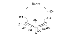
- FIG. 3 is a plan view when the slide device according to the first embodiment of the present invention is removed from the proximal end boom.
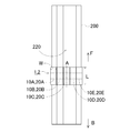
- FIG. 4 is a plan view when the slide device according to Embodiment 2 of the present invention is removed from the base end boom.
- Bottom view showing the shape of the slide device and the shape of the distal boom used in the structural analysis of the embodiment.
- a perspective view of a slide device according to Embodiment 1A A perspective view of a slide device according to Embodiment 1A.
- FIG. 9 is a perspective view showing a structural analysis result of a breaking load when the distal end boom is supported by the slide device according to the comparative example or the slide device according to Example 1C.
- the sliding device is a sliding device of a telescopic boom used for a crane, an aerial work vehicle, and the like.
- a distal boom on the distal side is incorporated into a proximal boom proximal to the boom.
- This slide device includes a plurality of slide plates arranged in a circumferential direction on an inner wall of the proximal end boom so that the proximal end boom slidably supports the distal end boom.
- a notch is formed in a part of the plurality of slide plates in order to prevent a reduction in the breaking load of the distal boom.
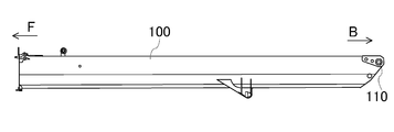
- FIG. 1 is a side view of a base end boom 100 provided with a slide device according to Embodiment 1 of the present invention.
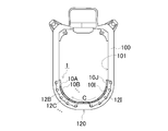
- FIG. 2 is an enlarged front view of the distal end side F of the proximal end boom 100.
- the base end boom 100 is formed in a rectangular and rectangular shape in side view.
- a boom foot 110 is provided for connection to the revolving superstructure of the crane.
- an opening 101 is formed in the distal end F as shown in FIG. 2 for inserting a not-shown distal end boom.
- the bottom 120 is curved downward.
- a sliding device 1 is provided on the inner wall of the bottom part 120 to slidably support the distal end boom.
- the slide device 1 includes slide plates 10A to 10J arranged along the inner wall of the bottom 120.
- the slide plates 10A-10J are arranged in the circumferential direction of the base end boom 100.
- the slide plates 10A to 10J are simply referred to as plates. Next, the configuration of the slide plates 10A to 10J will be described with reference to FIGS.
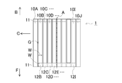
- FIG. 3 is a plan view of the slide device 1 when detached from the base end boom 100.
- FIG. 4 is a front view thereof.
- the circumferential direction C in FIGS. 3 and 4 is a direction corresponding to the circumferential direction C of the base end boom 100 shown in FIG.
- the slide plates 10A to 10J are formed in a rectangular shape in plan view, that is, in bottom view.
- the slide plates 10A to 10J have the same shape and size.
- the slide plates 10A to 10J have their longitudinal directions parallel to each other in a state where the positions of the front end sides F are aligned.
- the slide plates 10A-10J are arranged in the short direction, that is, in the circumferential direction C shown in FIG.
- the slide plates 10A to 10J have their longitudinal directions oriented in the extending direction of the telescopic boom.
- a gap G is provided between the adjacent slide plates 10A-10J in the circumferential direction C, as shown in FIG.
- the slide plates 10A to 10J are connected to each other at the bottom 120 while the gap G remains.
- the slide plates 10A-10J can be arranged along the curved bottom 120 of the proximal boom 100 as shown in FIG.
- chamfered portions 11 are formed on the distal end side F and the proximal end side B of the slide plates 10A-10J to facilitate sliding of the distal end boom.
- notches 12B-12I are formed on the distal end side F of the slide plate 10B-10I located at the center side in order to reduce the breaking load of the distal end boom.
- the notch 12B-12I has a concave shape in which the upper surface of the slide plate 10B-10I is cut out at a constant depth from the distal end F toward the proximal end B.
- the width of the notch 12B-12I is the same as the width W of the slide plate 10B-10I, and its length is the same as the width W.
- the shape of the notches 12B-12I is a square shape in bottom view. As a result, the notches 12B-12I have an effect of suppressing a reduction in the breaking load of the distal boom.
- the notches 12B-12I are not formed on the slide plates 10A and 10J at both ends in the circumferential direction C of the slide device 1, but are formed only on the center slide plate 10B-10I.
- the entire shape of the notches 12B-12I is a symmetrical shape with the center line A passing through the center of the slide device 1 in the circumferential direction C as the axis of symmetry.
- the center line A is a line that is parallel to the reference line just below the reference line of the base end boom 100 when attached to the base end boom 100.
- the center line A is a line extending in the direction in which the telescopic boom extends.
- the notches 12B-12I are formed in such an overall shape, so that the overall shape of the slide device 1 is symmetrical. As a result, the notches 12B-12I have an effect of further suppressing a reduction in the breaking load when the distal boom is extended.
- the operation of the notches 12B-12I in the slide device 1 will be described with reference to FIGS. 5A, 5B, 6, 7A, and 7B.
- the reference numeral 12 is used instead of the reference numerals 12B-12I, and the notch 12 is referred to.
- the reference numeral 10 is used instead of the reference numerals 10A-10J, and the slide plate is referred to as the slide plate 10.
- FIG. 5A is a cross-sectional view of the conventional slide device 5 and the distal end boom 200 when the distal end boom 200 is contracted.
- FIG. 5B is a cross-sectional view of the conventional slide device 5 and the distal boom 200 when the distal boom 200 is extended.
- FIG. 6 is a conceptual diagram of the proximal boom 100 when the distal boom 200 is extended.
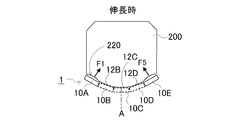
- FIG. 7A is a cross-sectional view of the slide device 1 and the distal boom 200 according to the first embodiment when the distal boom 200 is reduced.
- FIG. 7B is a cross-sectional view of the slide device 1 and the distal boom 200 according to the first embodiment when the distal boom 200 is extended.
- FIGS. 5A, 5B, 7A, and 7B show cross sections of the conventional slide device 5 and the distal end side F of the slide device 1 according to the first embodiment.
- the outer shape of the bottom 220 of the distal end boom 200 is simplified to a shape in which five flat plates form a part of a polygon in a cross-sectional view.
- the conventional slide device 5 and the slide device 1 according to the first embodiment are also simplified to a configuration including five slide plates that support five flat plates of the bottom 220, respectively.
- 7A and 7B, the slide plates 10A-10E are formed with notches 12B-12D in the slide plates 10B-10D. 6 omits detailed structures of the distal-side boom 200 and the proximal-side boom 100 for easy understanding, and has a rectangular cross-sectional shape.
- the slide plates 50A to 50E are indicated as slide plates 50.
- the bottom 220 of the distal boom 200 is surrounded by the slide plates 50A-50E of the slide device 5, as shown in FIG. 5A. Thereby, the deformation of the bottom portion 220 toward the outside of the distal end boom 200 is suppressed.
- notches 12 are not formed in the slide plates 10A and 10E at both ends, but the notches 12 are located between the slide plates 10A and 10E. Cutouts 12B-12D are formed in the slide plates 10B-10D at different positions. Therefore, the flat plates at both ends of the bottom 220 face the slide plates 10A and 10E without the notch 12, respectively. As a result, the flat plates at both ends of the bottom portion 220 are in a state in which the slide plates 10A and 10E suppress deformation to the outside of the distal end boom 200.
- the three flat plates at the center of the bottom 220 face the slide plates 10B-10D having the notches 12B-12D. Since the notches 12B-12D are formed on the distal end side F of the slide plates 10B-10D, the central three flat plates of the bottom portion 220 can be deformed to the outside of the distal end boom 200 at the distal end side F. is there.
- a portion of the bottom portion 220 is deformed toward the inside of the distal boom 200, and another portion is deformed toward the outside of the distal boom 200.
- the portion deformed inward and the portion deformed outward are adjacent to each other. Thereby, these parts function as buckling nodes.
- the buckling strength of the distal boom 200 increases.
- the entire shape of the notches 12B-12D is symmetric with respect to the center line A. For this reason, the positions of the nodes are symmetrical, and the buckling strength is further increased.
- the sliding device 1 more effectively suppresses a decrease in the breaking load of the distal boom 200 than the conventional sliding device 5.
- the center slide plates 10B-10D are located on the bottom side of the slide plates 10A, 10E at both ends, and are more susceptible to load. For this reason, the bottom 220 makes strong contact with the slide plates 10B-10D, and the reaction force applied to the bottom 220 is large.
- the notches 12B-12D are formed in the center slide plate 10B-10D where the reaction force is large, so that the bottom 220 is prevented from being largely deformed toward the inside of the distal end boom 200. Further, since the entire shape of the notches 12B to 12D is symmetrical as described above, the bottom 220 is not easily deformed in one direction. As a result, a decrease in the breaking load of the distal boom 200 is further suppressed.
- the portion of the slide plates 10B-10D from the front end side F to the same length as the width W is a portion where the reaction force is increased by the moment M described with reference to FIG.
- the reaction force is large in a range from the front end side F of the slide plates 10B to 10D to a length of 1/4 to 1/2 of the width W. Since notches 12B-12D are formed in this portion of slide plates 10B-10D, the reaction force is not easily transmitted to bottom 220. Further, since the notches 12B-12D are formed to have the same width as the width W of the slide plates 10B-10D, a reaction force is not easily applied to the bottom 220. As a result, a reduction in the breaking load of the distal boom 200 is further suppressed.
- the slide plate 10 is arranged such that the distal end F is aligned in the circumferential direction C with the bottom 120 inside the base end boom 100. Are lined up.
- a notch 12 is formed in the front end side F of the slide plate 10 that is disposed apart from both ends in the circumferential direction C of the slide plate 10. For this reason, in the slide device 1, the buckling strength is increased, and a decrease in the breaking load of the distal end boom 200 can be suppressed. As a result, the slide device 1 can prevent breakage of the distal end boom 200 and enhance safety.
- the notch 12 is formed to have the same width as the width W of the slide plate 10 and the same length as the width W. That is, the notch 12 is formed in a square shape. However, the shape of the notch 12 is arbitrary as long as the notch 12 is formed on the front end side F of the slide plate 10.
- the notch 12 may be polygonal in plan view.
- the notch 12 is desirably a quadrangle in plan view. It is more desirable that the notch 12 is formed in a rectangular shape.
- the quadrangle is a polygon surrounded by four line segments, and the line segment may be a curved line, for example, a curved line or a wavy line.
- a rectangle refers to a quadrangle having four equal angles, and the rectangle may be, for example, a square having four equal angles and equal side lengths.
- FIGS. 8 to 10 are perspective views of the notch 12 of the slide plate 10 provided in the slide device 1.
- the notch 12 does not need to be formed from the tip of the slide plate 10 and may be formed on the tip side F of the slide plate 10 as described above.
- the notch 12 preferably extends to the proximal side B from the distal end of the slide plate 10 where the notch 12 is not formed.
- the notch 12 may be formed in a range from the tip of the slide plate 10 to the same length as the width W. This is because the portion where the above-mentioned reaction force becomes large is located on the rear end side of the slide plate 10 from the front end.
- the width K W and length K L of formula 1-3, when the plan view shape of the notch 12 is non-rectangular, cutout 12 minimum width is the minimum length. Further, when the notch 12 is not of a fixed depth, for example, when the bottom of the notch 12 is inclined, the depth KT is the minimum depth.
- the slide device 1 can further reduce the contact with the distal end boom 200 in the portion where the reaction force is large. As a result, the slide device 1 can further suppress a decrease in the breaking load of the distal end boom 200.
- the length of the notch 12 may be longer than the width W.
- the sliding function as the slide plate 10 is smaller than the desirable shape described above, the contact with the distal end boom 200 can be prevented at the portion where the reaction force is large. As a result, the slide device 1 can suppress a decrease in the breaking load of the distal boom 200.
- the notch 12 may be formed in at least one of the slide plates 10 other than the slide plates 10 at both ends in the circumferential direction C.
- the notch 12 is preferably formed in at least one of the slide plates 10 located at positions away from both ends in the circumferential direction C.
- the entire shape of the slide device 1 in which the notch 12 is formed may be symmetrical with respect to a center line A parallel to the reference line of the base end boom 100.
- the shape of each of the notch 12 may be different.
- the length K L of the circumferential direction C slide plate 10 notches 12 formed located in the center of the can when greater than the length K L other notch 12.
- the slide device 1 can suppress a decrease in the breaking load of the distal end boom 200.
- the slide device 2 according to the second embodiment has a slide device in which notches 22A, 22J are formed in the slide plates 20A, 20J at both ends in the circumferential direction C among the slide plates 20A-20J in order to prevent stress concentration. It is.
- the configuration of the slide device 2 according to the second embodiment will be described with reference to FIGS. 11, 12, 13A, and 13B. In the second embodiment, a configuration different from the first embodiment will be described.
- the slide plate 20 is referred to by using the reference numeral 20 instead of the reference numerals 20A-20J.
- the slide plate 20 is simply referred to as a plate, like the slide plate 10.
- FIG. 11 is a plan view of the slide device 2 when detached from the proximal boom 100.
- FIG. FIG. 12 is a front view thereof.
- the slide device 2 is composed of slide plates 20A-20J formed in the same rectangular shape and size in plan view as the slide plates 10A-10J described in the first embodiment. ing.
- Slide plates 20A-20J are arranged similarly to slide plates 10A-10J of the first embodiment, as shown in FIG.
- Notches 22A and 22J are formed in the slide plates 20A and 20J arranged at both ends in the circumferential direction C among the slide plates 20A to 20J.
- the notches 22A and 22J are formed on the distal end side F of the slide plates 20A and 20J to have a width substantially equal to the width W of the slide plates 20A and 20J, and a length equal to the width W.
- the notches 22A and 22J are formed at a certain depth.
- FIG. 13A is a cross-sectional view of the slide device 2 and the distal boom 200 according to the second embodiment when the distal boom 200 is reduced.
- FIG. 13B is a cross-sectional view of the slide device 2 and the distal boom 200 according to the second embodiment when the distal boom 200 is extended.
- 13A and 13B show a cross section of the distal end side F of the slide device 2.
- the outer shape of the bottom 220 of the distal end boom 200 is simplified to a shape composed of five flat plates, as in FIGS. 5A, 5B, 7A, and 7B.
- the slide device 2 is simplified to a device having five slide plates.
- the slide device 2 has notches 22A and 22E formed in the slide plates 20A and 20E among the slide plates 20A to 20E.
- bending moments M1 and M2 act on the boundary between the bottom 220 and the side 230 due to the reaction force from the slide plates 50A and 50E. As a result, bending deformation occurs, and the distal boom 200 may be damaged.
- the notch 22 is not formed in the center three slide plates 20B-20D.
- the central three flat plates of the bottom 220 face the slide plates 20B-20D without the notches 22.
- these three flat plates are suppressed from being deformed toward the outside of the distal end boom 200.
- notches 22A and 22E are formed in the slide plates 20A and 20E at both ends.
- two flat plates at both ends of the bottom 220 face the slide plates 20A and 20E having the notches 22A and 22E.
- the notches 22A and 22E are formed on the front end side F of the slide plates 20A and 20E.
- the two flat plates at both ends of the bottom portion 220 are in a state in which deformation at the distal end F to the outside of the distal end boom 200 is not suppressed, that is, in a deformable state.
- the portion of the bottom 220 where stress concentration is eased is not easily biased. Further, the bending moments M3 and M4 are reduced, and bending deformation of the distal boom 200 is less likely to occur. As a result, the distal end boom 200 is less likely to be damaged.
- the notches 22 are formed in the slide plates 20 arranged at both ends in the circumferential direction C among the slide plates 20. For this reason, the slide device 2 can alleviate stress concentration of the distal end boom 200 and prevent bending deformation. As a result, the slide device 2 can prevent breakage of the distal end boom 200 and enhance safety.
- the notch 22 is formed to have the same width as the width W of the slide plate 20 and the same length as the width W from the tip.
- the notch 22 only needs to be formed on the distal end side F of the slide plate 20.
- the shape of the slide plate 20 is arbitrary as in the first embodiment.
- the notch 22 is preferably a quadrangle in plan view, and more preferably a rectangular shape in plan view.
- the notch 22 is desirably formed in the shape and size described with reference to FIGS.
- the notch 22 may be formed on the front end side F of the slide plate 20 similarly to the first embodiment, and the notch 22 may be formed on the other end of the slide plate 20 where the notch 22 is not formed. It is better to extend to the base end side B.
- the notches 22 are preferably formed at least on the slide plates 20 located at both ends in the circumferential direction C. In this case, it is preferable that at least one of the slide plates 20 between them has no notch 22. In other words, if there is a slide plate 20 in which the notch 22 is not formed in the slide plate 20 between the slide plates 20 at both ends in the circumferential direction C, the notch 22 is formed in another slide plate 20. Is also good.
- FIG. 14 is a bottom view showing the shapes of the slide devices 1 and 2 and the shape of the distal end boom 200 used in the structural analysis of the embodiment.
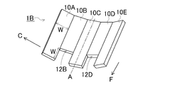
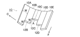
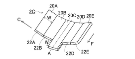
- 15 to 20 are perspective views of the slide devices 1A-1C and 2A-2C according to the examples 1A-1C and 2A-2C. 15 to 20, the lengths of the slide plates 10A to 10E and 20A to 20E are emphasized for easy understanding.
- the distal boom 200 having the same structure as the distal boom 200 shown in FIGS. 7A, 7B, 13A, and 13B was used.
- the distal end boom 200 provided with the bottom 220 formed of five rectangular flat plates arranged in the short direction with the long direction parallel as shown in FIG. 14 was used.
- the tip side boom 200 was manufactured by combining five rectangular flat plates into a shape curved convexly toward the bottom.
- slide devices 1 and 2 a device composed of five slide plates 10A to 10E and 20A to 20E similar to the forms shown in FIGS. 7A, 7B, 13A and 13B was used.
- the length L of the slide plates 10A-10E and 20A-20E was assumed to be three times the width W.
- the notches 12 and 22 were formed in one or two sections on the distal end side F among the divided sections when the slide plates 10A-10E and 20A-20E were divided into three in the front-rear direction.
- the width of the notches 12 and 22 is the same as the width W of the slide plates 10A-10E and 20A-20E, and the length is the same as or twice the width W.
- the slide devices 1A-1C and 2A-2C shown in FIGS. 15 to 20 were manufactured.
- the notches 12 and 22 had a shape and a size satisfying the above-described equations (1) to (3).
- a slide device 5 in which the notches 12 and 22 were not formed was manufactured.
- the slide devices 1A-1C are slide devices corresponding to the slide device 1 described in the first embodiment. More specifically, as shown in FIG. 15, the slide device 1A includes a notch 12B having a length equal to the width W in three slide plates 10B-10D arranged at the center among the slide plates 10A-10E. 12D is the formed device. As shown in FIG. 16, the slide device 1B is a device in which cutouts 12B and 12D having the same length as the slide device 1A are formed in slide plates 10B and 10D adjacent to the slide plates 10A and 10E at both ends. As shown in FIG. 17, the slide device 1C is a device in which notches 12B-12D are formed in three slide plates 10B-10D arranged on the center side.
- the length of the center notch 12C is twice the width W, and the lengths of the other notches 12B and 12D are the same as the width W.
- the overall shape of any of the slide devices 1A-1C is symmetrical with respect to a center line A passing through the center in the circumferential direction C.
- the slide devices 2A-2C are slide devices corresponding to the slide device 2 described in the second embodiment. More specifically, as shown in FIG. 18, the slide device 2A includes notches 22A, 22E having the same length as the width W in two slide plates 20A, 20E arranged at both ends of the slide plates 20A-20E. Is an apparatus in which is formed. In the slide device 2B, as shown in FIG. 19, in addition to the two slide plates 20A and 20E arranged at both ends, a notch 22C having the same length as the notches 22A and 22E is formed in the center slide plate 20C. Device. As shown in FIG.
- notches 22A, 22B, 22D, and 22E having the same length as the width W are formed on all the slide plates 20A, 20B, 20D, and 20E except for the center slide plate 20C.
- the overall shape of the slide devices 2A-2C is also symmetrical with respect to a center line A passing through the center in the circumferential direction C, similarly to the slide devices 1A-1C.
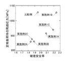
- FIG. 21 is a graph showing the structural analysis results of the slide devices 1A-1C and 2A-2C according to Examples 1A-1C and 2A-2C.
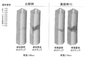
- FIG. 22 is a perspective view showing a structural analysis result of a breaking load when the distal end boom 200 is supported by the slide device 5 according to the comparative example or the slide device 1C according to Example 1C.
- FIG. 23 is a perspective view showing a structural analysis result of local stress when the distal end boom 200 is supported by the slide device 5 according to the comparative example or the slide device 2A according to Example 2A.
- Examples 1A-1C have a higher fracture safety factor than the comparative example. Further, as shown in FIG. 22, in Example 1C, the load at which the distal end boom 200 is broken is higher than in the comparative example. From these results, it can be seen that the sliding device 1 according to Embodiments 1A-1C and the corresponding Embodiment 1 suppresses a lowering of the breaking load of the distal boom 200 than the conventional sliding device 5. And it turns out that the damage of the front end side boom 200 is prevented.
- Examples 2A to 2C have smaller local stresses at the rated load than Comparative Examples. From these results, it can be seen that the stress concentration is reduced in Examples 2A-2C and the corresponding slide device 2 according to Embodiment 2 as compared with the conventional slide device 5. Further, as shown in FIG. 23, in Example 2A, the local stress is smaller at the corner between the bottom and the side of the distal boom 200 than in the comparative example. And since the slide device 2 has a symmetrical shape, the local stress is made more uniform. From this result, it can be seen that bending deformation is suppressed.
- the present invention is not limited to the above embodiment.
- the bottom 120 of the proximal boom 100 and the bottom 220 of the distal boom 200 are curved downward.
- the present invention is not limited to this.
- the shape of the bottom 120 of the proximal boom 100 is arbitrary as long as the slide plates 10 and 20 can be arranged in the circumferential direction.
- the shape of the bottom 120 may be a flat shape.
- the slide devices 1 and 2 have ten slide plates 10 and 20.
- the present invention is not limited to this.
- the slide devices 1 and 2 only need to include a plurality of slide plates 10 and 20.
- notches 12 and 22 may be formed on the distal end side F of at least one of the plurality of slide plates 10 and 20. With such a configuration, it is possible to prevent breakage of the distal end boom 200 and enhance the safety of the telescopic boom.
- the slide devices 1 and 2 may include three or more slide plates 10 and 20.
- the notch 12 is formed in at least one of the plates 10 and 20 other than the slide plates 10 and 20 located at both ends in the circumferential direction C of the base end boom 100. It is good to be.
- the notch 22 is preferably formed at least on the plate 20 located at both ends in the circumferential direction C of the base end boom 100.
- notches 12 and 22 are formed in at least one of the plurality of slide plates 10 and 20, however, the notches 12 and 22 form a part of the slide plates 10 and 20. What is necessary is just to have the shape of a groove
- the slide plates 10 and 20 have a short length in the longitudinal direction, and a tip of the short slide plate 10 or 20 is connected to another slide plate 10 or 20.
- the slide plates 10 and 20 have notches 12 and 22 on the distal end side F when viewed as a whole, because the slide plates 10 and 20 are shifted longitudinally and rearward from the distal end of the slide plate 20. May be used.
- some of the slide plates 10 and 20 are placed on the distal end side F of the other slide plates 10 and 20 because the tip positions of the plurality of slide plates 10 and 20 are not aligned.
- 20 may be provided with notches 12 and 22 extending to the proximal side B from the distal end.
- the notches 12 and 22 have a constant depth, but the notches 12 and 22 are not limited to shapes having a constant depth.
- a shape having an inclined surface that becomes deeper toward the distal end side F may be used. Even with such a shape, breakage of the distal end boom 200 can be prevented and safety can be improved. Further, when the inclined surface reaches the tip, the manufacture is easy.
- the bottoms of the notches 12 and 22 are flat, but the bottoms of the notches 12 and 22 are not limited to flat surfaces.
- it may be a curved surface depressed downward. Even with such a shape, breakage of the distal end boom 200 can be prevented and safety can be improved.
- the slide plates 10 and 20 have the longitudinal direction oriented in the front-rear direction, but the short direction may be oriented in the front-rear direction.
- the slide plates 10 and 20 need only be arranged on the bottom inside the base end boom 100 and arranged in the circumferential direction C of the base end boom 100.
- the present invention is applicable to all construction machines having a telescopic boom.
- the present invention is applicable to rough terrain cranes, truck cranes, aerial work vehicles, and the like.
Landscapes
- Engineering & Computer Science (AREA)
- Mechanical Engineering (AREA)
- Jib Cranes (AREA)
Abstract
スライド装置(1)は、先端側ブームと、先端側ブームが挿入された基端側ブーム(100)と、を備える伸縮式ブームに設けられ、先端側ブームをスライド可能に支持するスライド装置である。スライド装置(1)は、基端側ブーム(100)の底部(120)の内壁に配置され、基端側ブーム(100)の周方向に並べられた複数のスライドプレート(10A-10J)を備え、複数のスライドプレート(10A-10J)のうち、少なくとも1つは、先端側に他のプレートの先端よりも基端側へ延びる切り欠き(12B-12I)を有する。
Description
本発明はスライド装置及びクレーンに関する。
伸縮式ブームでは、先端側に位置するブーム(以下、先端側ブームという)をそのブームより基端側にあるブーム(以下、基端側ブームという)がスライド可能に保持している。このような伸縮式ブームには、基端側ブームの内側に、先端側ブームをスライド可能に支持するスライド装置が設けられたものがある。
例えば、特許文献1には、先端側ブームの軸方向に延在する複数の溝を有するプレート状のスライド装置が開示されている。特許文献1に記載のスライド装置は、基端側ブームの内側に設けられている。そして、溝の先端と基端の位置が揃えられている。特許文献1に記載のスライド装置では、複数の溝がブームの周方向に変形することで、先端側ブームが縮小して基端側ブームに収容されたときの、基端側ブームに生じる応力が緩和されている。
特許文献1に記載のスライド装置は、先端側ブームが縮小して基端側ブームに収容されたときの、基端側ブームに生じる応力を緩和しているだけである。すなわち、特許文献1は、先端側ブームが伸長したときに、スライド装置が先端側ブームにかかる応力を緩和しているかどうかを明らかにしていない。また、そのときの、破壊荷重が抑制されているかどうかを明らかにしていない。
本発明は、上記の課題を解決するためになされたもので、先端側ブームが伸長したときの、先端側ブームの破損を防止して伸縮式ブームの安全性を高めたスライド装置及びクレーンを提供することを目的とする。
上記の目的を達成するため、本発明の第1の観点に係るスライド装置は、
先端側ブームと、該先端側ブームが挿入された基端側ブームと、を備える伸縮式ブームに設けられ、前記先端側ブームをスライド可能に支持するスライド装置であって、
前記基端側ブームの底部の内壁に配置され、前記基端側ブームの周方向に並べられた複数のプレートを備え、
前記複数のプレートのうちの少なくとも1つは、先端側に他のプレートの先端よりも基端側へ延びる切り欠きを有する、
ことを特徴とする。
先端側ブームと、該先端側ブームが挿入された基端側ブームと、を備える伸縮式ブームに設けられ、前記先端側ブームをスライド可能に支持するスライド装置であって、
前記基端側ブームの底部の内壁に配置され、前記基端側ブームの周方向に並べられた複数のプレートを備え、
前記複数のプレートのうちの少なくとも1つは、先端側に他のプレートの先端よりも基端側へ延びる切り欠きを有する、
ことを特徴とする。
前記複数のプレートは、先端の位置を揃えた状態で、前記基端側ブームに並べられ、
前記切り欠きは、前記複数のプレートのうちの少なくとも1つの先端側に形成され、凹形状を有していてもよい。
前記切り欠きは、前記複数のプレートのうちの少なくとも1つの先端側に形成され、凹形状を有していてもよい。
前記スライド装置は、
前記プレートを3つ以上備え、
前記切り欠きは、
前記基端側ブームの周方向の両端に位置するプレート以外の少なくとも一つのプレートに形成されていてもよい。
前記プレートを3つ以上備え、
前記切り欠きは、
前記基端側ブームの周方向の両端に位置するプレート以外の少なくとも一つのプレートに形成されていてもよい。
前記スライド装置は、
前記プレートを3つ以上備え、
前記切り欠きは、
少なくとも、前記基端側ブームの周方向の両端に位置するプレートに形成されていてもよい。
前記プレートを3つ以上備え、
前記切り欠きは、
少なくとも、前記基端側ブームの周方向の両端に位置するプレートに形成されていてもよい。
前記切り欠きの形状は、底面視長方形であってもよい。
前記スライド装置は、
前記基端側ブームの基準線に平行な軸を対称軸とする対称形状であってもよい。
前記基端側ブームの基準線に平行な軸を対称軸とする対称形状であってもよい。
本発明の第2の観点に係るクレーンは、第1の観点に係るスライド装置が設けられた伸縮式ブームを備える、
ことを特徴とする。
ことを特徴とする。
本発明の構成によれば、先端側ブームが伸長したときの、先端側ブームの破損が防止され、伸縮式ブームの安全性が高められる。
以下、本発明の実施の形態に係るスライド装置及びクレーンについて図面を参照して詳細に説明する。なお、図中、同一又は同等の部分には同一の符号を付す。また、本明細書において、先端側とは、伸縮式ブームが伸長する側のことをいい、基端側とは、その反対側のことをいう。
(実施の形態1)
実施の形態1に係るスライド装置は、クレーン、高所作業車等に使用される伸縮式ブームのスライド装置である。伸縮式ブームでは、先端側にある先端側ブームが、そのブームより基端側にある基端側ブームに組み入れられている。このスライド装置は、基端側ブームが先端側ブームをスライド可能に支持するため、基端側ブームの内壁の周方向に並べられる複数のスライドプレートを備えている。そして、複数のスライドプレートの一部には、先端側ブームの破壊荷重の低下を防止するために、切り欠きが形成されている。
実施の形態1に係るスライド装置は、クレーン、高所作業車等に使用される伸縮式ブームのスライド装置である。伸縮式ブームでは、先端側にある先端側ブームが、そのブームより基端側にある基端側ブームに組み入れられている。このスライド装置は、基端側ブームが先端側ブームをスライド可能に支持するため、基端側ブームの内壁の周方向に並べられる複数のスライドプレートを備えている。そして、複数のスライドプレートの一部には、先端側ブームの破壊荷重の低下を防止するために、切り欠きが形成されている。
まず、図1-図2を参照して、スライド装置が備え付けられた基端側ブームとスライド装置の構成について説明する。以下、クレーンに使用される伸縮式ブームを例に説明する。
図1は、本発明の実施の形態1に係るスライド装置が備え付けられた基端側ブーム100の側面図である。図2は、基端側ブーム100の先端側Fの拡大正面図である。
図1に示すように、基端側ブーム100は、側面視長方形かつ角筒の形状に形成されている。基端側ブーム100の基端側Bには、クレーンの旋回体に連結するためのブームフット110が設けられている。これに対して、先端側Fには、図示しない先端側ブームを挿入するため、図2に示すように、開口101が形成されている。その開口101では、底部120が下側に湾曲している。そして、底部120の内壁には、先端側ブームをスライド可能に支持するため、スライド装置1が設けられている。
スライド装置1は、底部120の内壁に沿って配置されたスライドプレート10A-10Jで構成されている。そして、スライドプレート10A-10Jは、基端側ブーム100の周方向に並べられている。なお、本明細書では、スライドプレート10A-10Jのことを単にプレートともいう。
次に、図3-図4を参照して、スライドプレート10A-10Jの構成について説明する。
次に、図3-図4を参照して、スライドプレート10A-10Jの構成について説明する。
図3は、基端側ブーム100から取り外したときのスライド装置1の平面図である。図4は、その正面図である。なお、図3及び図4における周方向Cとは、図2に示す基端側ブーム100の周方向Cに対応する方向のことである。
スライドプレート10A-10Jは、図3に示すように、平面視、すなわち底面視で長方形状に形成されている。そして、スライドプレート10A-10Jは、それぞれの形状、大きさが揃えられている。また、スライドプレート10A-10Jは、先端側Fの位置が揃えられた状態で、互いに長手方向を平行にしている。スライドプレート10A-10Jは、10A、10B・・の順序で短手方向に、すなわち図3に示す周方向Cに並べられている。これにより、スライドプレート10A-10Jは、長手方向を伸縮式ブームの伸長方向に向ける。
周方向Cに隣り合うスライドプレート10A-10J同士の間には、図4に示すように、隙間Gが設けられている。そして、スライドプレート10A-10J同士は、その隙間Gがある状態のまま、底部120側で連結されている。スライドプレート10A-10Jは、その連結部分が屈曲することにより、図2に示すように、基端側ブーム100の湾曲した底部120に沿って配置することができる。
図3に戻って、スライドプレート10A-10Jの先端側Fと基端側Bには、先端側ブームのスライドを容易にするため、面取り部11が形成されている。一方、スライドプレート10A-10Jのうち、中央側にあるスライドプレート10B-10Iの先端側Fには、先端側ブームの破壊荷重が低下しにくくするため、切り欠き12B-12Iが形成されている。
切り欠き12B-12Iは、先端側Fから基端側Bに向かってスライドプレート10B-10Iの上面側が一定の深さで切り欠かれた凹形状を有する。その切り欠き12B-12Iの幅は、スライドプレート10B-10Iの幅Wと同じであり、その長さは、幅Wと同じである。換言すると、切り欠き12B-12Iの形状は、底面視正方形状である。これにより、切り欠き12B-12Iは、先端側ブームの破壊荷重の低下を抑制する作用を生じさせる。
また、切り欠き12B-12Iは、スライド装置1の周方向Cの両端にあるスライドプレート10A、10Jには形成されておらず、中央側のスライドプレート10B-10Iだけに形成されている。これにより、切り欠き12B-12I全体の形状は、スライド装置1の周方向Cの中心を通る中心線Aを対称軸とする対称形状である。ここで、中心線Aは、基端側ブーム100に取り付けたときに基端側ブーム100の基準線の真下で基準線と平行になる線である。そして、中心線Aは、伸縮式ブームの伸長方向へ延びる線である。切り欠き12B-12Iは、このような全体形状に形成されることにより、スライド装置1全体の形状を対称形状としている。その結果、切り欠き12B-12Iは、先端側ブームを伸長したときの破壊荷重の低下をより抑制する作用を生じさせる。
次に、図5A、図5B、図6、図7A及び図7Bを参照して、スライド装置1での切り欠き12B-12Iの作用について説明する。
なお、以下の説明では、切り欠きを総称する場合、符号12B-12Iではなく符号12を用い、切り欠き12と称するものとする。また、スライドプレートを総称する場合も、符号10A-10Jではなく符号10を用い、スライドプレート10と称するものとする。
なお、以下の説明では、切り欠きを総称する場合、符号12B-12Iではなく符号12を用い、切り欠き12と称するものとする。また、スライドプレートを総称する場合も、符号10A-10Jではなく符号10を用い、スライドプレート10と称するものとする。
図5Aは、先端側ブーム200が縮小したときの、従来のスライド装置5と先端側ブーム200の断面図である。図5Bは、先端側ブーム200が伸長したときの、従来のスライド装置5と先端側ブーム200の断面図である。図6は、先端側ブーム200が伸長したときの、基端側ブーム100の概念図である。図7Aは、先端側ブーム200が縮小したときの、実施の形態1に係るスライド装置1と先端側ブーム200の断面図である。図7Bは、先端側ブーム200が伸長したときの、実施の形態1に係るスライド装置1と先端側ブーム200の断面図である。
なお、図5A、図5B、図7A及び図7Bは、従来のスライド装置5と実施の形態1に係るスライド装置1の先端側Fの断面を示している。また、理解を容易にするため、先端側ブーム200の底部220の外形が、5つの平板が断面視で多角形の一部を形成する形状に簡略化されている。従来のスライド装置5と実施の形態1に係るスライド装置1も、底部220の5つの平板それぞれを支持する5枚のスライドプレートを備える構成に簡略化されている。また、図7A及び図7Bでは、スライドプレート10A-10Eのうち、スライドプレート10B-10Dに切り欠き12B-12Dが形成されているものとしている。また、図6は、理解を容易にするため、先端側ブーム200、基端側ブーム100の詳細な構造を省略し、それらの形状を断面長方形状としている。図6では、スライドプレート50A-50Eをスライドプレート50と表示している。
従来のスライド装置5では、先端側ブーム200の底部220は、図5Aに示すように、スライド装置5のスライドプレート50A-50Eによって囲まれている。これにより、底部220は、先端側ブーム200の外側に向かって変形することが抑制されている。
この状態で、先端側ブーム200が伸長すると、底部220は、スライドプレート50A-50Eと接触する。その結果、スライドプレート50A-50Eから底部220に反力が加えられる。すなわち、図5Bに示すように、底部220に接触反力F1-F5が加えられる。底部220は、外側への変形が抑制されているものの、内側への変形は抑制されてないので、先端側ブーム200の内側に向かって変形する。すなわち、底部220の5つの平板が内側に向かってしなった形状に変形する。
図6に示すように、先端側ブーム200が伸長した場合、先端側ブーム200の先端には、その基端よりも大きいモーメントMが作用する。このため、図5Bに示すスライド装置5の先端側Fでは、上述した反力が大きく、その反力によって先端側ブーム200の底部220が変形しやすい。これにより、反力が大きすぎる場合には、底部220の5つの平板がより内側に向かってしなった形状に変形して、先端側ブーム200の座屈荷重が低下する。その結果、破壊荷重が低下する。
これに対して、実施の形態1に係るスライド装置1には、図7Aに示すように、両端のスライドプレート10A、10Eに切り欠き12が形成されていないが、それらの間の、両端から離れた位置にあるスライドプレート10B-10Dに切り欠き12B-12Dが形成されている。このため、底部220の両端にある平板は、切り欠き12がないスライドプレート10A、10Eそれぞれと対向する。その結果、底部220の両端の平板は、スライドプレート10A、10Eによって、先端側ブーム200の外側へ変形することが抑制された状態にある。一方、底部220の中央にある3つの平板は、切り欠き12B-12Dがあるスライドプレート10B-10Dと対向する。切り欠き12B-12Dは、スライドプレート10B-10Dの先端側Fに形成されているため、底部220の中央3つの平板は、その先端側Fで、先端側ブーム200の外側に変形可能な状態にある。
この状態で、先端側ブーム200が伸長すると、両端にあるスライドプレート10A、10Eの先端側Fに先端側ブーム200の底部220が接触してその荷重が加えられる。これにより、底部220には、スライドプレート10A、10Eから反力が加えられる。その結果、図7Bに示すように、底部220の、スライドプレート10A、10Eと接触する部分に接触反力F1、F5が加えられる。これにより、底部220のその部分が先端側ブーム200の内側に向かって変形する。
一方で、中央側にあるスライドプレート10B-10Dの先端側Fには、切り欠き12B-12Dが形成されているので、その先端側Fでは、スライドプレート10B-10Dが底部220と接触しない。これにより、底部220に接触反力が加えられない。その結果、先端側Fで、底部220が先端側ブーム200の外側に向かって変形する。
このように、底部220の一部分が先端側ブーム200の内側に向かって変形すると共に、他の部分が先端側ブーム200の外側に向かって変形する。そして、その内側に向かって変形する部分と外側に向かって変形する部分が隣接している。これにより、これらの部分が座屈の節として機能する。その結果、先端側ブーム200の座屈強度が高まる。さらに、図7Bに示すように、切り欠き12B-12D全体の形状が中心線Aに対して対称である。このため、その節の位置も対称となって座屈強度がより高まる。その結果、スライド装置1は、従来のスライド装置5よりも効果的に先端側ブーム200の破壊荷重の低下を抑制する。
また、中央側のスライドプレート10B-10Dは、両端のスライドプレート10A、10Eよりも底側にあり、より荷重がかかりやすい。このため、スライドプレート10B-10Dに底部220が強く接触し、底部220に加えられる反力も大きい。この反力が大きい中央側のスライドプレート10B-10Dに切り欠き12B-12Dが形成されているため、底部220が先端側ブーム200の内側に向かって大きく変形することが防止される。さらに、切り欠き12B-12D全体の形状が上述したように、対称であるため、底部220が偏った変形となりにくい。その結果、先端側ブーム200の破壊荷重の低下がより抑制される。
さらに、スライドプレート10B-10Dの、先端側Fから幅Wと同じ長さまでの部分は、図6を参照して説明したモーメントMによって、反力が大きくなる部分である。例えば、スライドプレート10B-10Dの、先端側Fから幅Wの1/4~1/2の長さまでの範囲で反力が大きい。スライドプレート10B-10Dの、この部分に切り欠き12B-12Dが形成されているため、底部220に反力が伝わりにくい。また、切り欠き12B-12Dがスライドプレート10B-10Dの幅Wと同じ幅に形成されているため、底部220に反力が加わりにくい。その結果、先端側ブーム200の破壊荷重の低下がさらに抑制される。
以上のように、本発明の実施の形態1に係るスライド装置1では、スライドプレート10が、基端側ブーム100の内側の底部120に周方向Cに、先端側Fが揃えられた状態で、並べられている。そして、スライドプレート10のうち、周方向Cの両端から離れて配置されたスライドプレート10の先端側Fに、切り欠き12が形成されている。このため、スライド装置1では、座屈強度を高めて、先端側ブーム200の破壊荷重の低下を抑制することができる。その結果、スライド装置1は、先端側ブーム200の破損を防止して安全性を高めることができる。
なお、スライド装置1では、切り欠き12が、スライドプレート10の幅Wと同じ幅、かつ幅Wと同じ長さに形成されている。すなわち、切り欠き12が正方形状に形成されている。しかし、切り欠き12は、スライドプレート10の先端側Fに切り欠き12形成されている限りにおいて、形状は任意である。
例えば、切り欠き12は、平面視で多角形であってもよい。この場合、切り欠き12は、平面視で四角形であることが望ましい。また、切り欠き12は、長方形状に形成されていることがより望ましい。ここで、四角形とは、4つの線分で囲まれた多角形のことであり、その線分は、曲線、例えば、湾曲した線、波線であってもよい。また、長方形とは、4つの角度が等しい四角形のことをいい、長方形は、例えば、4つの角度が等しく辺の長さが等しい正方形であってもよい。
次に、図8-図10を参照して、切り欠き12の望ましい形状、大きさについて、説明する。以下、切り欠き12が平面視で長方形である場合を例に説明する。
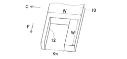
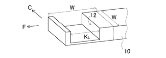
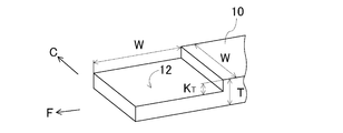
図8-図10は、スライド装置1が備えるスライドプレート10の切り欠き12の斜視図である。なお、図8-図10では、理解を容易にするため、面取り部11を省略している。
図8に示す切り欠き12の幅KWは、スライドプレート10の幅をWとする場合に、
KW≧W/2・・・(式1)
を満たすとよい。
KW≧W/2・・・(式1)
を満たすとよい。
また、図9に示す切り欠き12の長さKLは、
KL≧W/3・・・(式2)
を満たすとよい。
KL≧W/3・・・(式2)
を満たすとよい。
なお、切り欠き12は、スライドプレート10の先端から形成されている必要はなく、上述したように、スライドプレート10の先端側Fに形成されていればよい。そして、切り欠き12は、切り欠き12が形成されていないスライドプレート10の先端よりも基端側Bへ延在しているとよい。例えば、切り欠き12は、スライドプレート10の先端から幅Wと同じ長さまでの範囲内に形成されるとよい。これは、上述した反力が大きくなる部分が、スライドプレート10の先端よりも後端側に位置するからである。
また、図10に示す切り欠き12の深さKTは、スライドプレート10の厚みをTとする場合に、
KT≧T/5・・・(式3)
を満たすとよい。また、深さKTは、3mm以上であるとよい。
なお、式1-3の幅KWと長さKLは、切り欠き12の平面視形状が長方形以外である場合、切り欠き12の最小幅、最小長さである。また、切り欠き12が一定の深さでなく、例えば、切り欠き12の底が傾斜している場合、深さKTは、最小深さである。
KT≧T/5・・・(式3)
を満たすとよい。また、深さKTは、3mm以上であるとよい。
なお、式1-3の幅KWと長さKLは、切り欠き12の平面視形状が長方形以外である場合、切り欠き12の最小幅、最小長さである。また、切り欠き12が一定の深さでなく、例えば、切り欠き12の底が傾斜している場合、深さKTは、最小深さである。
以上の形状に切り欠き12が形成されることにより、スライド装置1では、反力の大きくなる部分で先端側ブーム200との接触をより少なくすることができる。その結果、スライド装置1は、先端側ブーム200の破壊荷重の低下をより抑制することができる。
また、切り欠き12の長さは、幅Wよりも長くてもよい。上述した望ましい形状よりもスライドプレート10としてのスライド機能が小さくなるものの、反力の大きくなる部分で先端側ブーム200との接触を防ぐことができる。その結果、スライド装置1は、先端側ブーム200の破壊荷重の低下を抑制することができる。
切り欠き12は、周方向Cの両端にあるスライドプレート10以外のスライドプレート10のうち、少なくとも1つのスライドプレート10に形成されているとよい。換言すると、切り欠き12は、周方向Cの両端から離れた位置にあるスライドプレート10のうちの少なくとも1つに形成されているとよい。この場合、切り欠き12が形成されたスライド装置1全体の形状は、基端側ブーム100の基準線に平行な中心線Aに対して対称形状であるとよい。
また、両端から離れた位置にあるスライドプレート10それぞれに切り欠き12が形成されている場合、切り欠き12それぞれの形状は、異なっていてもよい。この場合、周方向Cの中央に位置するスライドプレート10に形成された切り欠き12の長さKLは、他の切り欠き12の長さKLよりも大きいとよい。このような形態でも、スライド装置1が先端側ブーム200の破壊荷重の低下を抑制することができる。
(実施の形態2)
実施の形態2に係るスライド装置2は、応力集中を防止するため、スライドプレート20A-20Jのうち、周方向Cの両端にあるスライドプレート20A、20Jに切り欠き22A、22Jが形成されたスライド装置である。以下、図11、図12、図13A及び図13Bを参照して、実施の形態2に係るスライド装置2の構成を説明する。実施の形態2では、実施の形態1と異なる構成について説明する。
実施の形態2に係るスライド装置2は、応力集中を防止するため、スライドプレート20A-20Jのうち、周方向Cの両端にあるスライドプレート20A、20Jに切り欠き22A、22Jが形成されたスライド装置である。以下、図11、図12、図13A及び図13Bを参照して、実施の形態2に係るスライド装置2の構成を説明する。実施の形態2では、実施の形態1と異なる構成について説明する。
なお、実施の形態2においても、切り欠きを総称する場合、符号22A、22Jではなく符号22を用いて切り欠き22と称するものとする。また、スライドプレートを総称する場合、符号20A-20Jではなく符号20を用いてスライドプレート20と称するものとする。また、本明細書では、スライドプレート20のことを、スライドプレート10と同様に、単にプレートともいう。
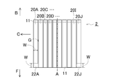
図11は、基端側ブーム100から取り外したときのスライド装置2の平面図である。図12は、その正面図である。
図11及び図12に示すように、スライド装置2は、実施の形態1で説明したスライドプレート10A-10Jと同様の平面視長方形の形状、大きさに形成されたスライドプレート20A-20Jで構成されている。
図11及び図12に示すように、スライド装置2は、実施の形態1で説明したスライドプレート10A-10Jと同様の平面視長方形の形状、大きさに形成されたスライドプレート20A-20Jで構成されている。
スライドプレート20A-20Jは、図11に示すように、実施の形態1のスライドプレート10A-10Jと同様に配置されている。そして、スライドプレート20A-20Jのうち、周方向Cの両端に配置されたスライドプレート20Aと20Jには、切り欠き22A、22Jが形成されている。
切り欠き22A、22Jは、スライドプレート20Aと20Jの先端側Fに、スライドプレート20Aと20Jの幅Wとほぼ同じ幅、かつ幅Wと同じ長さに形成されている。また、切り欠き22A、22Jは、一定の深さに形成されている。そして、切り欠き22A、22Jが形成されることにより、スライド装置2全体の形状は、実施の形態1と同様、周方向Cの中心を通る中心線Aに対して対称形状である。これにより、切り欠き22A、22Jは、先端側ブーム200の応力集中を緩和させる作用を生じさせる。
次に、図5A、図5B、図13A及び図13Bを参照して、スライド装置2での切り欠き22A、22Eの作用について説明する。
図13Aは、先端側ブーム200が縮小したときの、実施の形態2に係るスライド装置2と先端側ブーム200の断面図である。図13Bは、先端側ブーム200が伸長したときの、実施の形態2に係るスライド装置2と先端側ブーム200の断面図である。
なお、図13A及び図13Bでは、スライド装置2の先端側Fの断面を図示している。また、理解を容易にするため、先端側ブーム200の底部220の外形が、図5A、図5B、図7A及び図7Bと同様に、5つの平板からなる形状に簡略化されている。また、スライド装置2も、5枚のスライドプレートを備える装置に簡略化されている。そして、スライド装置2は、スライドプレート20A-20Eのうち、スライドプレート20Aと20Eに切り欠き22A、22Eが形成されているものとしている。
従来のスライド装置5は、実施の形態1で説明したように、先端側ブーム200が伸長すると、スライドプレート50A-50Eによって底部220に反力が加えられる。これにより、底部220には、図5Bに示す接触反力F1-F5が加わる。スライド装置5の先端側Fで反力が大きいことから、接触反力F1-F5は、底部220の、スライド装置5の先端側Fに接触する部分に強く作用する。このため、応力集中が発生して、先端側ブーム200が破損されてしまうことがある。
また、図5Bに示すように、底部220と側面部230の境界には、スライドプレート50Aと50Eからの反力によって曲げモーメントM1、M2が作用する。その結果、曲げ変形が生じて、先端側ブーム200が破損されてしまうことがある。
これに対して、実施の形態2に係るスライド装置2では、中央3つのスライドプレート20B-20Dに切り欠き22が形成されていない。このため、図13Aに示すように、底部220の中央3つの平板には、その切り欠き22がないスライドプレート20B-20Dと対向する。これにより、これら3つの平板は、先端側ブーム200の外側に向かって変形することが抑制される状態となる。これに対して、両端にあるスライドプレート20A、20Eには、切り欠き22A、22Eが形成されている。このため、底部220の両端2つの平板には、切り欠き22A、22Eがあるスライドプレート20Aと20Eに対向する。そして、切り欠き22A、22Eは、スライドプレート20A、20Eの先端側Fに形成されている。このため、底部220の両端2つの平板は、先端側Fで、先端側ブーム200の外側に変形することが抑制されていない状態、すなわち変形可能な状態にある。
この状態で、先端側ブーム200が伸長すると、図13Bに示すように、底部220には、スライドプレート20B-20Dによって接触反力F2-F4が加わる。このため、底部220の中央3つの平板は、先端側ブーム200の内側に向かって変形する。一方、底部220の両端2つの平板には、スライドプレート20A、20Eに切り欠き22A、22Eが形成されているため、接触反力が加わらない。その結果、底部220の両端2つの平板は、先端側ブーム200の外側に向かって変形する。これにより、先端側ブーム200の応力集中が緩和される。そして、切り欠き22A、22Eが中心線Aに対して対称形状であるため、底部220の、応力集中が緩和される箇所が偏りにくい。また、曲げモーメントM3、M4が小さくなり、先端側ブーム200の曲げ変形が生じにくくなる。その結果、先端側ブーム200が破損しにくくなる。
以上のように、本発明の実施の形態2に係るスライド装置2では、スライドプレート20のうち、周方向Cの両端に配置されたスライドプレート20に切り欠き22が形成されている。このため、スライド装置2は、先端側ブーム200の応力集中を緩和すると共に、曲げ変形を防止することができる。その結果、スライド装置2は、先端側ブーム200の破損を防止して安全性を高めることができる。
なお、スライド装置2では、切り欠き22が、スライドプレート20の幅Wと同じ幅、かつ先端から幅Wと同じ長さに形成されている。しかし、スライド装置2では、スライドプレート20の先端側Fに切り欠き22が形成されていればよく、その場合、実施の形態1と同様、スライドプレート20の形状は任意である。
例えば、実施の形態1と同様に、切り欠き22は、平面視で四角形であることが望ましく、平面視で長方形状に形成されていることがより望ましい。また、実施の形態1と同様に、切り欠き22は、図8-図10を参照して説明した形状、大きさに形成されていることが望ましい。また、切り欠き22は、実施の形態1と同様に、スライドプレート20の先端側Fに形成されていればよく、切り欠き22は、切り欠き22が形成されていない他のスライドプレート20の先端よりも基端側Bへ延在しているとよい。
また、切り欠き22は、周方向Cの両端に位置するスライドプレート20に少なくとも形成されているとよい。この場合、それらの間にあるスライドプレート20の少なくとも1つが、切り欠き22を有しない形態であるとよい。換言すると、周方向Cの両端のスライドプレート20の間にあるスライドプレート20に、切り欠き22が形成されていないスライドプレート20があれば、他のスライドプレート20に切り欠き22が形成されていてもよい。
次に、実施の形態1及び2について実施例を説明する。
次に、実施の形態1及び2について実施例を説明する。
図14は、実施例の構造解析で使用したスライド装置1、2の形状と先端側ブーム200の形状を示す底面図である。図15-図20は、実施例1A-1C及び2A-2Cに係るスライド装置1A-1C及び2A-2Cの斜視図である。
なお、図15-図20では、理解を容易にするため、スライドプレート10A-10E及び20A-20Eの長さを強調している。
なお、図15-図20では、理解を容易にするため、スライドプレート10A-10E及び20A-20Eの長さを強調している。
実施例の構造解析では、図7A、図7B、図13A及び図13Bに示す先端側ブーム200と同様の構造の先端側ブーム200を使用した。詳細には、図14に示す、長手方向を平行にして短手方向に並べられた5つの長方形状の平板で構成された底部220を備える先端側ブーム200を使用した。なお、図示しないが、先端側ブーム200は、5つの長方形状の平板を底部側に向かって凸状に湾曲した形状に組み合わせて作製した。
また、スライド装置1、2には、図7A、図7B、図13A及び図13Bに示す形態と同様の、5つのスライドプレート10A-10E及び20A-20Eで構成される装置を使用した。スライドプレート10A-10E及び20A-20Eの長さLは幅Wの3倍であるとした。
切り欠き12、22は、スライドプレート10A-10E及び20A-20Eを前後方向に3つに区切ったときの、区切られた各区画のうち、先端側Fの1区画又は2区画に形成した。また、切り欠き12、22は、幅がスライドプレート10A-10E及び20A-20Eの幅Wと同じで、長さがその幅Wと同じ又は2倍とした。これにより、図15-図20に示すスライド装置1A-1C及び2A-2Cを作製した。なお、切り欠き12、22は、上述した式(1)-式(3)を満たす形状、大きさにした。
また、比較例として、切り欠き12、22が形成されてないスライド装置5を作製した。
ここで、スライド装置1A-1Cは、実施の形態1で説明したスライド装置1に相当するスライド装置である。詳細には、スライド装置1Aは、図15に示すように、スライドプレート10A-10Eのうち、中央側に配置された3つのスライドプレート10B-10Dに、長さが幅Wと同じ切り欠き12B-12Dが形成された装置である。スライド装置1Bは、図16に示すように、両端のスライドプレート10A、10Eに隣接するスライドプレート10B、10Dに、スライド装置1Aと同じ長さの切り欠き12B、12Dが形成された装置である。スライド装置1Cは、図17に示すように、中央側に配置された3つのスライドプレート10B-10Dに、切り欠き12B-12Dが形成された装置である。それら切り欠き12B-12Dのうち、中央にある切り欠き12Cの長さが、幅Wの2倍、その他の切り欠き12B、12Dの長さが幅Wと同じである。いずれのスライド装置1A-1C全体の形状も、周方向Cの中心を通る中心線Aに対して対称形状である。
また、スライド装置2A-2Cは、実施の形態2で説明したスライド装置2に相当するスライド装置である。詳細には、スライド装置2Aは、図18に示すように、スライドプレート20A-20Eのうち、両端に配置された2つのスライドプレート20A、20Eに、長さが幅Wと同じ切り欠き22A、22Eが形成された装置である。スライド装置2Bは、図19に示すように、両端に配置された2つのスライドプレート20A、20Eに加えて、中央のスライドプレート20Cに切り欠き22A、22Eと同じ長さの切り欠き22Cが形成された装置である。スライド装置2Cは、図20に示すように、中央のスライドプレート20Cを除いたスライドプレート20A、20B、20D及び20E全てに、長さが幅Wと同じ切り欠き22A、22B、22D及び22Eが形成された装置である。なお、スライド装置2A-2Cの全体の形状も、スライド装置1A-1Cと同様に、周方向Cの中心を通る中心線Aに対して対称形状である。
これらのスライド装置1A-1C及び2A-2Cが基端側ブーム100に設けられた伸縮式ブームについて、先端側ブーム200に定格負荷を加えたときの構造解析を行った。また、先端側ブーム200に定格負荷よりも大きい負荷を加えて先端側ブーム200が破壊される段階の構造解析を行った。そして、それらの構造解析から破壊安全率と定格負荷時の局部応力を求めた。それらの結果を図21-図23と表1に示す。
図21は、実施例1A-1C及び2A-2Cに係るスライド装置1A-1C及び2A-2Cの構造解析結果を示すグラフである。図22は、比較例に係るスライド装置5又は実施例1Cに係るスライド装置1Cで先端側ブーム200を支持したときの破壊荷重の構造解析結果を示す斜視図である。図23は、比較例に係るスライド装置5又は実施例2Aに係るスライド装置2Aで先端側ブーム200を支持したときの局部応力の構造解析結果を示す斜視図である。

表1及び図21に示すように、実施例1A-1Cは、比較例よりも破壊安全率が高い。また、図22に示すように、実施例1Cは、先端側ブーム200が破壊される荷重が比較例よりも高い。これらの結果から、実施例1A-1Cとこれらに相当する実施の形態1に係るスライド装置1で、従来のスライド装置5よりも先端側ブーム200の破壊荷重の低下が抑制されることがわかる。そして、先端側ブーム200の破損が防止されることがわかる。
また、表1及び図21に示すように、実施例2A-2Cは、比較例よりも定格負荷時の局部応力が小さい。この結果から、実施例2A-2Cとこれらに相当する実施の形態2に係るスライド装置2で、従来のスライド装置5よりも、応力集中が緩和されることがわかる。また、図23に示すように、実施例2Aでは、比較例よりも先端側ブーム200の底部と側部との間のコーナー部で、局部応力が小さい。そして、スライド装置2が対称形状であるため、局部応力がより均一化されている。この結果から、曲げ変形が抑制されていることがわかる。
以上、本発明の実施の形態を説明したが、本発明は上記の実施の形態に限定されるものではない。例えば、実施の形態1及び2では、基端側ブーム100の底部120と先端側ブーム200の底部220が下側に向かって湾曲している。しかし、本発明は、これに限定されない。本発明では、基端側ブーム100の底部120の形状は、スライドプレート10、20を周方向に向かって並べることが可能である限りにおいて、任意である。例えば、底部120の形状は、平坦な形状であってもよい。
また、実施の形態1及び2では、スライド装置1及び2がスライドプレート10、20を10枚、備えている。しかし、本発明は、これに限定されない。本発明では、スライド装置1及び2は、スライドプレート10、20を複数枚、備えていればよい。そして、複数枚のスライドプレート10、20のうち、少なくとも1つのスライドプレート10、20の先端側Fに切り欠き12、22が形成されていればよい。このような構成であれば、先端側ブーム200の破損を防止して伸縮式ブームの安全性を高めることができる。
また、本発明では、スライド装置1及び2がスライドプレート10、20を3つ以上、備えているとよい。この場合、破壊荷重の低下を防止するためには、切り欠き12は、基端側ブーム100の周方向Cの両端に位置するスライドプレート10、20以外のプレート10、20の少なくとも一つに形成されているとよい。また、応力集中を防止するためには、切り欠き22は、少なくとも、基端側ブーム100の周方向Cの両端に位置するプレート20に形成されているとよい。
実施の形態1及び2では、複数のスライドプレート10、20のうち、少なくとも1つに切り欠き12、22が形成されているが、切り欠き12、22は、スライドプレート10、20の一部を切り取ることにより得られる溝、凹部、孔、欠落部分等の形状を有していればよい。これにより、切り欠き12、22は、先端側ブーム200の底部220との接触が防止されているとよい。その結果、スライド装置1及び2では、スライドプレート10、20が実際に切り取られたか否かを問わない。
例えば、スライド装置1及び2は、複数のスライドプレート10、20のうち、少なくとも1つの長手方向の長さが短く、その長さが短いスライドプレート10、20の先端が、他のスライドプレート10、20の先端よりも長手方向かつ後方にずれていることにより、スライドプレート10、20全体で視ると、その長さが短いスライドプレート10、20が先端側Fに切り欠き12、22を有することとなる形態であってもよい。換言すると、スライド装置1及び2は、複数のスライドプレート10、20の先端の位置が揃っていないことにより、一部のスライドプレート10、20が、その先端側Fに、他のスライドプレート10、20の先端よりも基端側Bへ延びる切り欠き12、22を有する形態であってもよい。
実施の形態1及び2では、切り欠き12、22が一定の深さであるが、切り欠き12、22は、一定の深さを有する形状に限られない。例えば、先端側Fに向かって深くなる傾斜面を有する形状であってもよい。このような形状でも、先端側ブーム200の破損を防止して安全性を高めることができる。また、その傾斜面が先端まで達する場合、その製造が容易である。
また、実施の形態1及び2では、切り欠き12、22の底が平面であるが、切り欠き12、22の底は、平面に限られない。例えば、下に向かって窪んだ曲面であってもよい。このような形状でも、先端側ブーム200の破損を防止して安全性を高めることができる。
実施の形態1及び2では、スライドプレート10、20が長手方向を前後方向に向けているが、短手方向を前後方向に向けてもよい。本発明では、スライドプレート10、20は、基端側ブーム100の内側の底部に配置され、基端側ブーム100の周方向Cに並べられていればよい。
本発明は、伸縮式ブームを備える建設機械全般に適用可能である。例えば、ラフテレーンクレーン、トラッククレーン、高所作業車等にも適用可能である。
本発明は、本発明の広義の精神と範囲を逸脱することなく、様々な実施形態及び変形が可能とされるものである。また、上述した実施形態は、本発明を説明するためのものであり、本発明の範囲を限定するものではない。つまり、本発明の範囲は、実施形態ではなく、請求の範囲によって示される。そして、請求の範囲内及びそれと同等の発明の意義の範囲内で施される様々な変形が、本発明の範囲内とみなされる。
本出願は、2018年8月7日に出願された、日本国特許出願特願2018-148172号に基づく。本明細書中に日本国特許出願特願2018-148172号の明細書、特許請求の範囲、図面全体を参照として取り込むものとする。
1,1A-1C スライド装置
2,2A-2C スライド装置
5 スライド装置
11 面取り部
12,12B-12I 切り欠き
22,22A-22E,22J 切り欠き
10A-10J スライドプレート
20A-20J スライドプレート
50A-50E スライドプレート
100 基端側ブーム
101 開口
110 ブームフット
120 底部
200 先端側ブーム
220 底部
230 側面部
A 中心線
B 基端側
C 周方向
F 先端側
F1-F5 接触反力
G 隙間
L 長さ
T 厚み
W 幅
W 長さ
KW 幅
KL 長さ
KT 深さ
M モーメント
M1-M4 曲げモーメント
2,2A-2C スライド装置
5 スライド装置
11 面取り部
12,12B-12I 切り欠き
22,22A-22E,22J 切り欠き
10A-10J スライドプレート
20A-20J スライドプレート
50A-50E スライドプレート
100 基端側ブーム
101 開口
110 ブームフット
120 底部
200 先端側ブーム
220 底部
230 側面部
A 中心線
B 基端側
C 周方向
F 先端側
F1-F5 接触反力
G 隙間
L 長さ
T 厚み
W 幅
W 長さ
KW 幅
KL 長さ
KT 深さ
M モーメント
M1-M4 曲げモーメント
Claims (7)
- 先端側ブームと、該先端側ブームが挿入された基端側ブームと、を備える伸縮式ブームに設けられ、前記先端側ブームをスライド可能に支持するスライド装置であって、
前記基端側ブームの底部の内壁に配置され、前記基端側ブームの周方向に並べられた複数のプレートを備え、
前記複数のプレートのうちの少なくとも1つは、先端側に他のプレートの先端よりも基端側へ延びる切り欠きを有する、
スライド装置。 - 前記複数のプレートは、先端の位置を揃えた状態で、前記基端側ブームに並べられ、
前記切り欠きは、前記複数のプレートのうちの少なくとも1つの先端側に形成され、凹形状を有する、
請求項1に記載のスライド装置。 - 前記スライド装置は、
前記プレートを3つ以上備え、
前記切り欠きは、
前記基端側ブームの周方向の両端に位置するプレート以外の少なくとも一つのプレートに形成されている、
請求項1又は2に記載のスライド装置。 - 前記スライド装置は、
前記プレートを3つ以上備え、
前記切り欠きは、
少なくとも、前記基端側ブームの周方向の両端に位置するプレートに形成されている、
請求項1又は2に記載のスライド装置。 - 前記切り欠きの形状は、底面視長方形である、
請求項1から4のいずれか1項に記載のスライド装置。 - 前記スライド装置は、
前記基端側ブームの基準線に平行な軸を対称軸とする対称形状である、
請求項1から5のいずれか1項に記載のスライド装置。 - 請求項1から6のいずれか1項に記載のスライド装置が設けられた伸縮式ブームを備える、
クレーン。
Applications Claiming Priority (2)
| Application Number | Priority Date | Filing Date | Title |
|---|---|---|---|
| JP2018148172A JP7220346B2 (ja) | 2018-08-07 | 2018-08-07 | スライド装置 |
| JP2018-148172 | 2018-08-07 |
Publications (1)
| Publication Number | Publication Date |
|---|---|
| WO2020031920A1 true WO2020031920A1 (ja) | 2020-02-13 |
Family
ID=69414912
Family Applications (1)
| Application Number | Title | Priority Date | Filing Date |
|---|---|---|---|
| PCT/JP2019/030588 Ceased WO2020031920A1 (ja) | 2018-08-07 | 2019-08-02 | スライド装置及びクレーン |
Country Status (2)
| Country | Link |
|---|---|
| JP (1) | JP7220346B2 (ja) |
| WO (1) | WO2020031920A1 (ja) |
Citations (4)
| Publication number | Priority date | Publication date | Assignee | Title |
|---|---|---|---|---|
| JPH09501384A (ja) * | 1993-06-16 | 1997-02-10 | エーツェー エンジニアリング ウント コンサルティング シュペツィアルマシーネン ゲゼルシャフト ミット ベシュレンクテル ハフツンク | 入れ子式ブーム |
| US6499612B1 (en) * | 2001-07-27 | 2002-12-31 | Link-Belt Construction Equipment Co., L.P., Lllp | Telescoping boom assembly with rounded profile sections and interchangeable wear pads |
| JP2008265980A (ja) * | 2007-04-23 | 2008-11-06 | Tadano Ltd | 伸縮ブームのスライド装置 |
| JP2013129491A (ja) * | 2011-12-21 | 2013-07-04 | Kobe Steel Ltd | スライド支持装置及びスライド支持装置の設置方法 |
-
2018
- 2018-08-07 JP JP2018148172A patent/JP7220346B2/ja active Active
-
2019
- 2019-08-02 WO PCT/JP2019/030588 patent/WO2020031920A1/ja not_active Ceased
Patent Citations (4)
| Publication number | Priority date | Publication date | Assignee | Title |
|---|---|---|---|---|
| JPH09501384A (ja) * | 1993-06-16 | 1997-02-10 | エーツェー エンジニアリング ウント コンサルティング シュペツィアルマシーネン ゲゼルシャフト ミット ベシュレンクテル ハフツンク | 入れ子式ブーム |
| US6499612B1 (en) * | 2001-07-27 | 2002-12-31 | Link-Belt Construction Equipment Co., L.P., Lllp | Telescoping boom assembly with rounded profile sections and interchangeable wear pads |
| JP2008265980A (ja) * | 2007-04-23 | 2008-11-06 | Tadano Ltd | 伸縮ブームのスライド装置 |
| JP2013129491A (ja) * | 2011-12-21 | 2013-07-04 | Kobe Steel Ltd | スライド支持装置及びスライド支持装置の設置方法 |
Also Published As
| Publication number | Publication date |
|---|---|
| JP2020023378A (ja) | 2020-02-13 |
| JP7220346B2 (ja) | 2023-02-10 |
Similar Documents
| Publication | Publication Date | Title |
|---|---|---|
| KR20200034333A (ko) | 디스플레이용 기판 | |
| JP2014507584A5 (ja) | ||
| JP5222489B2 (ja) | 伸縮ブームのスライド装置 | |
| JP7220346B2 (ja) | スライド装置 | |
| WO1992002062A1 (de) | Festkörperlaser | |
| WO2007092235A3 (en) | Waveguide laser having reduced cross-sectional size and/or reduced optical axis distortion | |
| JP2010089919A (ja) | 伸縮ブーム | |
| JP2013079521A (ja) | 岩盤破砕装置及び岩盤破砕方法 | |
| TW202211284A (zh) | 電子源及其製造方法,以及發射器及具備該發射器之裝置 | |
| US11659112B1 (en) | Scanner and load bearing structure thereof | |
| WO2012084425A1 (de) | Bandleiter-laserverstärker und laseranordnung mit einem bandleiter-laserverstärker | |
| DE102017114732A1 (de) | Broad-Area Laser-Wellenleitermodul | |
| JP3216307U (ja) | 剪断刃 | |
| CN102725100B (zh) | 连接杆的断裂方法 | |
| CN102862914B (zh) | 支脚盘和起重机 | |
| JP6953091B2 (ja) | エンジン発電機 | |
| RU2346121C2 (ru) | Правило | |
| US20230108606A1 (en) | Actuator and fluid control apparatus | |
| JP2006347722A (ja) | 移動式クレーンの伸縮ブーム | |
| JP2006273473A (ja) | 伸縮ブーム | |
| JP2012082576A (ja) | 埋設部材撤去装置 | |
| JP2016001010A (ja) | ロッド固定ユニット、及び、それを用いた伸縮ロッドユニット | |
| Yonetani et al. | Relationship between the grindability and the various microstructures of alumina ceramics | |
| BR0103246A (pt) | Dispositivo para o apoio de cofragens e armação de fuso para utilização com um dispositivo para o apoio de cofragens | |
| JP2018070984A (ja) | 多段式熱処理治具 |
Legal Events
| Date | Code | Title | Description |
|---|---|---|---|
| 121 | Ep: the epo has been informed by wipo that ep was designated in this application |
Ref document number: 19846173 Country of ref document: EP Kind code of ref document: A1 |
|
| NENP | Non-entry into the national phase |
Ref country code: DE |
|
| 122 | Ep: pct application non-entry in european phase |
Ref document number: 19846173 Country of ref document: EP Kind code of ref document: A1 |