WO2020031862A1 - 光ファイバの損失測定装置および光ファイバの損失測定方法 - Google Patents
光ファイバの損失測定装置および光ファイバの損失測定方法 Download PDFInfo
- Publication number
- WO2020031862A1 WO2020031862A1 PCT/JP2019/030327 JP2019030327W WO2020031862A1 WO 2020031862 A1 WO2020031862 A1 WO 2020031862A1 JP 2019030327 W JP2019030327 W JP 2019030327W WO 2020031862 A1 WO2020031862 A1 WO 2020031862A1
- Authority
- WO
- WIPO (PCT)
- Prior art keywords
- light
- frequency
- optical fiber
- mode
- loss
- Prior art date
- Legal status (The legal status is an assumption and is not a legal conclusion. Google has not performed a legal analysis and makes no representation as to the accuracy of the status listed.)
- Ceased
Links
Images


Classifications
-
- G—PHYSICS
- G01—MEASURING; TESTING
- G01M—TESTING STATIC OR DYNAMIC BALANCE OF MACHINES OR STRUCTURES; TESTING OF STRUCTURES OR APPARATUS, NOT OTHERWISE PROVIDED FOR
- G01M11/00—Testing of optical apparatus; Testing structures by optical methods not otherwise provided for
- G01M11/30—Testing of optical devices, constituted by fibre optics or optical waveguides
- G01M11/31—Testing of optical devices, constituted by fibre optics or optical waveguides with a light emitter and a light receiver being disposed at the same side of a fibre or waveguide end-face, e.g. reflectometers
- G01M11/3109—Reflectometers detecting the back-scattered light in the time-domain, e.g. OTDR
-
- G—PHYSICS
- G01—MEASURING; TESTING
- G01M—TESTING STATIC OR DYNAMIC BALANCE OF MACHINES OR STRUCTURES; TESTING OF STRUCTURES OR APPARATUS, NOT OTHERWISE PROVIDED FOR
- G01M11/00—Testing of optical apparatus; Testing structures by optical methods not otherwise provided for
- G01M11/30—Testing of optical devices, constituted by fibre optics or optical waveguides
- G01M11/31—Testing of optical devices, constituted by fibre optics or optical waveguides with a light emitter and a light receiver being disposed at the same side of a fibre or waveguide end-face, e.g. reflectometers
- G01M11/3109—Reflectometers detecting the back-scattered light in the time-domain, e.g. OTDR
- G01M11/3145—Details of the optoelectronics or data analysis
Definitions
- the present invention relates to an optical fiber loss measuring device and an optical fiber loss measuring method, and more particularly, to an optical fiber that propagates a plurality of modes and an optical fiber transmission path in an optical transmission system using the same.
- the present invention relates to an optical fiber loss measuring device and an optical fiber loss measuring method for measuring loss in a distributed and non-destructive manner.
- FMF Frew
- fiber Mode multiplexing transmission using a mode
- Non-Patent Document 1 by using the optical time domain reflectometer having a plurality of channels (Optical Time Domain Reflectometry, hereinafter referred to as OTDR), excited any mode, for example, the LP 01 to FMF, occurs when propagating through the FMF and backward Rayleigh scattering light by the light of the mode, another mode the excitation by mode, for example, LP 11 loss difference for each mode LP 01 and LP 11 by light coupled to the mode from the back Rayleigh scattering light topographically Evaluation methods have been proposed.
- OTDR Optical Time Domain Reflectometry
- Non-Patent Document 2 between the OTDR and the subject optical fiber, arranged mode filter for removing higher order mode, based on the two OTDR waveform if not installed and when installed the mode filter LP 01 and A method of distributively evaluating the loss of each mode of LP 11 has been proposed.
- the rear Rayleigh scattered light generated in a plurality of modes in FMF is, a certain mode change point of the optical fiber transmission path in (such as bending of the connecting points or cable), the LP 01 Rayleigh scattered light and Rayleigh scattered light of LP 11 are mixed. Therefore, the loss for each mode cannot be correctly evaluated.
- the obtained loss value is the value of the mode with the smallest loss (mode with strong Rayleigh scattering intensity) among the plurality of modes, so that the loss is small as a transmission path evaluation, and the transmission path is erroneously determined to be a good transmission path. there is a possibility.
- the present invention has been made in view of such a conventional problem, and an object of the present invention is to provide an optical test system capable of accurately measuring the loss of each mode at each position of the optical fiber in an optical fiber in which a plurality of modes propagate. Is to provide.
- the optical fiber loss measuring device described in one embodiment transmits light of a first frequency in a predetermined mode to an optical fiber to be measured that propagates a plurality of modes.
- An optical fiber loss measuring device that measures the loss for each propagation mode at each position of the measurement target optical fiber, and becomes a crosstalk of the probe light, light of another mode different from the predetermined mode, A frequency obtained by adding a frequency corresponding to the Brillouin frequency shift of the predetermined mode to one frequency
- a light separating unit that removes
- An optical fiber loss measuring method described in another embodiment is characterized in that a light of a first frequency in a predetermined mode is used as a probe light with respect to an optical fiber to be measured propagating in a plurality of modes.
- OTDR Optical Time Domain Main Reflemetry
- FIG. 1 is a block diagram illustrating an example of an optical fiber loss measuring device according to a first embodiment. It is a figure showing an example of a spectrum in two outputs. It is a figure showing an example of a Rayleigh scattering waveform of an unnecessary mode. It is a figure showing an example of a Rayleigh scattering waveform of a desired mode.
- FIG. 6 is a block diagram illustrating an example of an optical fiber loss measuring device according to a second embodiment.
- the optical fiber loss measuring device described in the embodiment for a measured optical fiber that propagates a plurality of modes, the light of the first frequency of a predetermined mode as a probe light of the measured optical fiber
- OTDR Optical Time Domain Main Reflemetry
- Crosstalk at a second frequency which is a frequency to which a frequency corresponding to the Brillouin frequency shift of As the suppression light
- a crosstalk suppression light inputting means for inputting from the near end of the optical fiber to be measured, and removing the light of the second frequency from the light output from the near end of the optical fiber to be measured.
- Light separating means for separating the light of the first frequency
- propagation mode loss measuring means for measuring the loss of each propagation mode at each position of the optical fiber to be measured by measuring the intensity of the separated light; It has.
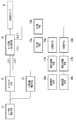
- FIG. 1 is a block diagram showing an example of the optical fiber loss measuring device according to the first embodiment.
- the optical fiber loss measuring device shown in FIG. 1 comprises a laser light generating means 11, an optical pulsing means 12 and an optical frequency controlling means 13 whose inputs are connected to the laser light generating means 11, an optical pulsing means 12 and an optical A mode selecting / multiplexing / demultiplexing unit 14 having an input connected to each output of the frequency control unit 13; optical separating units 15a, 15b connected to the output of the mode selecting / multiplexing / demultiplexing unit 14;
- the light receiving means 16a, the digitizing processing means 17a, and the numerical calculation means 18a are connected in series to the optical receiving means 16b, the digitizing processing means 17b, and the numerical calculating means 18b connected in series to the light separating means 15b. Are shown.
- the mode selecting / combining means 14 has inputs 1 and 2, outputs 1 and 2, and an input / output unit connected to the near end of the optical fiber F to be measured.
- the optical fiber F to be measured is connected to the input / output unit of the mode selection / multiplexing / demultiplexing unit 14 of the optical fiber loss measuring device.
- the input 1 of the mode selection / multiplexing / demultiplexing means 14 is connected to the output of the optical pulsing means 12, and the input 2 is connected to the output of the optical frequency control means 13.
- the output 1 of the mode selecting / multiplexing / demultiplexing means 14 is connected to a light separating means 15a, and the output 2 is connected to a light separating means 15b.
- the light output from the laser light generating means 11 for generating coherent light is split into two, and one of the two split lights is pulsed by an optical pulsing means 12.
- the mode to be measured is selected by the mode selection / combining means 14 and input to the near end of the optical fiber F to be measured as probe light.
- the other of the two branched lights is given a mode difference of about 10 to 11 GHz corresponding to the Brillouin frequency shift of the optical fiber to be measured to the lower frequency side by the optical frequency control means 13, and then the mode is selected.
- a mode that causes crosstalk of the probe light is selected by the multiplexing means 14 and input to the near end of the measured optical fiber F as crosstalk suppression light.
- the light that causes crosstalk is used as crosstalk suppression light that causes Brillouin loss between the Rayleigh scattered lights of the probe light.
- the mode selecting / combining means 14 selects the mode of the light output from the near end of the optical fiber F to be measured, and outputs the light from output 1 or output 2. As the output 1, light in the same mode as the input 1, that is, light in the same mode as the probe light is selected and output. As the output 2, light in the same mode as the input 2, that is, light in the same mode as the crosstalk suppression light is selected and output.
- the reflected light of the crosstalk suppression light including the Rayleigh scattered light by the crosstalk suppression light is removed by the light separating means 15a and 15b, only the Rayleigh scattered light of the desired mode is output from the output 1 and the output 2.
- the optical receiving units 16a and 16b are separated and input to the optical receiving units 16a and 16b.
- the light separated by the light receiving means 16a and 16b is converted into an electric signal.
- the light separating means 15a and 15b remove the light of the frequency component of the crosstalk suppression light and transmit the light of the frequency component of the probe light.
- an optical filter can be used as the light separating means 15a, 15b.
- the electrical signals received by the light receiving units 16a and 16b are appropriately amplified, then digitized by the digitizing processing units 17a and 17b, and the Rayleigh scattered light for each distance is calculated using the numerical calculation units 18a and 18b. .
- the optical frequency control means 13 in FIG. 1 appropriately changes the frequency difference between the probe light and the crosstalk suppression light,
- the Rayleigh scattered light can be acquired by each of the numerical calculation means 18b corresponding to the output 2 and the frequency characteristic of the intensity of the Rayleigh scattered light can be acquired for each output.
- n i is the effective refractive index of any of its modes
- lambda is the wavelength.
- the Brillouin frequency shift varies depending on the propagating mode, and the obtained Brillouin spectrum information at an arbitrary position in each mode has a peak for each mode.
- the optical fiber loss measuring apparatus of the present embodiment suppresses Rayleigh scattered light by an unnecessary mode by utilizing the fact that this Brillouin spectrum has a different peak for each mode.
- the probe light of the light power P r is a case where an amplitude in LP 11, the Rayleigh scattered light having a power of P B01 and P B11 in both the LP 01 and LP 11.
- m ij and R ij are respectively a mode coupling point at the position z and a coefficient for mode conversion from the LP j1 mode to the LP i1 mode by Rayleigh scattering.
- the Rayleigh scattered light represented by the equation (2) becomes
- Equation 3 g Bx-y is Brillouin scattering coefficient due to crosstalk suppressed optical Rayleigh scattering and LP y of LP x, P i1 is crosstalk suppression light LP i1 at position z Power , ⁇ i1 are the loss factors of LP i1 .
- the frequency difference f B as Buriruanrosu crosstalk suppressed optical P 01 of the Rayleigh scattered light P B01 and LP 01 of LP 01 to be suppressed occurs strongly, Rayleigh scattering light power of the LP 01 P B01 can be reduced. At this time, the power of the Rayleigh scattered light of the LP 11 does not decrease because the frequency difference that acts greatly differs.
- the frequency difference between the probe light and the crosstalk suppressing light it is possible to accurately receive only the Rayleigh scattered light in the desired mode.
- the intensity waveform of the Rayleigh light scattering light relative to the distance LP 11 it is possible to obtain the loss of the desired mode.
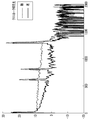
- the suppression of the unnecessary mode can be determined by the values of (Expression 3) and (Expression 4), that is, the output values of the numerical operation means 18a and 18b. What is necessary is just to make the output of 18b minimum. Further, a case where the ratio of the output of the numerical operation means 18b to the output of the numerical operation means 18a becomes minimum may be used. That is, as shown in FIG. 2, numerical computation means the intensity of Rayleigh scattered light is observed at 18b with respect to the frequency difference: the (For description of the present embodiment LP strength of 01), the frequency difference to obtain the loss of the desired mode Can be grasped.
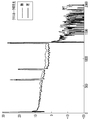
- FIGS. 3 and 4 show the distance between the unnecessary mode (LP 01 ) (FIG. 3) and the desired mode (LP 11 ) (FIG. 4) at the frequency difference at which the intensity of the Rayleigh scattered light obtained by the numerical calculation means 18b is minimized.
- the intensity waveform of the Rayleigh scattered light for each is shown by the presence or absence of the crosstalk suppression light.
- the intensity of the Rayleigh scattered light is shown in FIG. 3 (unnecessary mode) LP 01 is being suppressed by the crosstalk suppressed optical, shown in FIG. 4 (a desired mode) LP 11 is not suppressed.
- optical fiber loss measuring device of the present embodiment by injecting the crosstalk suppression light, unnecessary modes can be suppressed, and the intensity waveform of the Rayleigh scattered light of only the desired mode can be obtained.
- the optical fiber loss measuring device of the present embodiment in Rayleigh scattered light generated in a plurality of modes, Rayleigh scattered light other than the desired mode can be suppressed in the target optical fiber, and the desired It is possible to non-destructively measure only the loss of the mode. This makes it possible to measure the loss of each connection point, device, and other modes in the transmission path.
- FIG. 5 is a block diagram showing an example of the optical fiber loss measuring device according to the second embodiment.
- the mode in which the light separating units 15a and 15b such as frequency filters are used as the unit for removing the light of the frequency component of the crosstalk suppressing light has been described as an example.
- light separating means 25a and 25b using coherent detection are used instead of the light separating means 15a and 15b.
- the other configuration is the same as that of the optical fiber loss measuring device of the first embodiment, and the description is omitted.
- the coherent detection means of the light separation means 25a and 25b performs coherent detection with the output light of the output 1 or the output 2 using the light of the optical frequency of the input 1, that is, the light of the optical frequency of the laser light generating means as a reference hole, respectively.
- the light of the frequency component of the crosstalk suppression light may be removed to separate the intensity of the Rayleigh scattered light.
- the above configuration is an example, and an optical frequency difference corresponding to the Brillouin frequency shift is given between the probe light pulse and the crosstalk suppression light, and an arbitrary mode is selected, similarly to the optical fiber loss measuring device of the above embodiment. Any means can be used as long as it is an apparatus configuration that can excite and extract a signal of the intensity of Rayleigh scattered light in the time domain.
- the optical fiber loss measuring device of the present embodiment in Rayleigh scattered light generated in a plurality of modes, Rayleigh scattered light other than the desired mode can be suppressed in the target optical fiber, and the desired It is possible to non-destructively measure only the loss of the mode. This makes it possible to measure the loss of each connection point, device, and other modes in the transmission path.
- optical fiber loss measuring device of the above embodiment unlike the non-patent documents 1 and 2, crosstalk can be suppressed in the fiber under measurement by the Brillouin loss phenomenon, so Unnecessary modes can be suppressed.
- Non-Patent Documents 1 and 2 it is possible to measure a correct loss for each mode.
- the loss is determined based on the intensity waveform of the Rayleigh scattered light obtained in the desired mode. , The correct loss for each mode can be measured.
Landscapes
- Physics & Mathematics (AREA)
- Optics & Photonics (AREA)
- Chemical & Material Sciences (AREA)
- Analytical Chemistry (AREA)
- General Physics & Mathematics (AREA)
- Engineering & Computer Science (AREA)
- Microelectronics & Electronic Packaging (AREA)
- Testing Of Optical Devices Or Fibers (AREA)
Abstract
複数モードが伝搬する光ファイバにおいて、光ファイバの各位置におけるモード毎の損失を正確に測定可能な光試験システムを提供すること。OTDR法により測定する光ファイバの損失測定装置であって、前記プローブ光のクロストークとなる、前記所定のモードとは異なる別モードの光を、第1の周波数に対して前記所定のモードのブリルアン周波数シフトに相当する周波数を付与した周波数である第2の周波数でクロストーク抑圧光として、前記被測定対象光ファイバの近端から入力するクロストーク抑圧光入力手段と、前記被測定対象光ファイバの近端から出力される光のうち第2の周波数の光を除去して第1の周波数の光を分離する光分離手段と、前記分離した光の強度を測定することにより前記被測定対象光ファイバの各位置における各伝搬モードについての損失を測定する伝搬モード損失測定手段とを備えたことを特徴とする。
Description
本発明は、光ファイバの損失測定装置および光ファイバの損失測定方法に関し、詳細には、複数のモードを伝搬する光ファイバやそれを用いた光伝送システムにおける光ファイバ伝送路の各伝搬モードについての損失を分布的にかつ非破壊に測定するための光ファイバの損失測定装置および光ファイバの損失測定方法に関する。
近年、基幹通信網のトラフィック量の増加はめざましく、将来的にはPbps/1心級の大容量伝送が必要であると言われている。このような大容量化を目指し、現在の光ファイバ伝送路で用いられているシングルモード光ファイバの容量限界を打破する光ファイバとして、複数のモードを伝搬する数モード光ファイバ(以下、FMF(Few mode fiber)と称する)を用いたモード多重伝送が大きな注目を集めている。
FMFを用いた光伝送システムを実現するためには、光ファイバ伝送路を構成する光ファイバケーブルや接続点の良否を評価し、長期間にわたって運用・保守することが求められる。光ファイバ伝送路の良否判定において、光の損失は伝送容量や伝送距離を制限する主要な特性であり、特に、FMF伝送路ではモード毎に信号伝送を行う特性上、モード毎の損失を評価することが求められる。
非特許文献1では、複数チャネルを有する光時間領域反射計(Optical Time Domain Reflectometry、以下OTDRと称する)を用いて、任意のモード、例えばLP01をFMFに励振し、FMFを伝搬する際に生じた当該モードの光による後方レイリー散乱光と、励振したモードとは別のモード、例えばLP11モードに結合した光による後方レイリー散乱光からLP01とLP11のモード毎の損失差を分布的に評価する手法が提案されている。
非特許文献2では、OTDRと被対象光ファイバの間に、高次モードを除去するモードフィルタを配置し、モードフィルタを設置した場合と設置しない場合の2つのOTDR波形をもとにLP01およびLP11のモード毎の損失を分布的に評価する手法が提案されている。
M. Nakazawa et. al., "Measurement of mode coupling distribution along a few-mode fiber using a synchronous multi-channel OTDR" Opt. Express, Vol. 22, No.25, pp. 31299-31309 (2014).
H. Kubota, Y. Miyoshi, M. Ohashi, T. Mori, T. Matui, and K. Nakajima, "Mode-dependent loss measurement of a two-mode fiber using a conventional OTDR," IEICE Commum. Express, Vol. 5, pp. 429-434, (2016).
非特許文献1および2に記載の方法では、FMF中で複数のモードで発生する後方レイリー散乱光が、光ファイバ伝送路上のあるモード変換点(接続点やケーブルの曲げなど)において、LP01のレイリー散乱光とLP11のレイリー散乱光が混ざってしまう。そのため、モード毎の損失を正しく評価できない。特に、得られる損失値は、複数モードの内、最も損失の小さいモード(レイリー散乱強度が強いモード)の値となるため、伝送路評価として損失が小さく、良い伝送路と誤って判定してしまう可能性がある。
本発明はかかる従来の問題に鑑みなされたものであって、本発明の課題は、複数モードが伝搬する光ファイバにおいて、光ファイバの各位置におけるモード毎の損失を正確に測定可能な光試験システムを提供することにある。
上記の課題を解決するために、一実施形態に記載された光ファイバの損失測定装置は、複数のモードを伝搬する被測定対象光ファイバに対して、所定のモードの第1の周波数の光をプローブ光として前記被測定対象光ファイバの近端から入力し、前記被測定対象光ファイバの各位置で発生した後方散乱光の強度をOTDR(Optical Time Domain Refletometry)法により測定することにより、前記被測定対象光ファイバの各位置における各伝搬モードについての損失を測定する光ファイバの損失測定装置であって、前記プローブ光のクロストークとなる、前記所定のモードとは異なる別モードの光を、第1の周波数に対して前記所定のモードのブリルアン周波数シフトに相当する周波数を付与した周波数である第2の周波数でクロストーク抑圧光として、前記被測定対象光ファイバの近端から入力するクロストーク抑圧光入力手段と、前記被測定対象光ファイバの近端から出力される光のうち第2の周波数の光を除去して第1の周波数の光を分離する光分離手段と、前記分離した光の強度を測定することにより前記被測定対象光ファイバの各位置における各伝搬モードについての損失を測定する伝搬モード損失測定手段とを備えたことを特徴とする。
他の実施形態に記載された光ファイバの損失測定方法は、複数のモードを伝搬する被測定対象光ファイバに対して、所定のモードの第1の周波数の光をプローブ光として前記被測定対象光ファイバの近端から入力し、前記被測定対象光ファイバの各位置で発生した後方散乱光の強度をOTDR(Optical Time Domain Refletometry)法により測定することにより、前記被測定対象光ファイバの各位置における各伝搬モードについての損失を測定する光ファイバの損失測定方法であって、前記プローブ光を前記被測定対象光ファイバの近端から入力すると共に、前記プローブ光のクロストークとなる、前記所定のモードとは異なる別モードの光を、第1の周波数に対して前記所定のモードのブリルアン周波数シフトに相当する周波数を付与した周波数である第2の周波数でクロストーク抑圧光として、前記被測定対象光ファイバの近端から入力するクロストーク抑圧光入力ステップと、前記被測定対象光ファイバの近端から出力される光のうち第2の周波数の光を除去して第1の周波数の光を分離する光分離ステップと、前記分離した光の強度を測定することにより前記被測定対象光ファイバの各位置における各伝搬モードについての損失を測定する伝搬モード損失測定ステップとを含むことを特徴とする。
以下、図面を参照して本発明の実施の形態を詳細に説明する。
実施形態に記載された光ファイバの損失測定装置は、複数のモードを伝搬する被測定対象光ファイバに対して、所定のモードの第1の周波数の光をプローブ光として前記被測定対象光ファイバの近端から入力し、前記被測定対象光ファイバの各位置で発生した後方散乱光の強度をOTDR(Optical Time Domain Refletometry)法により測定することにより、前記被測定対象光ファイバの各位置における各伝搬モードについての損失を測定する光ファイバの損失測定装置であって、前記プローブ光のクロストークとなる、前記所定のモードとは異なる別モードの光を、第1の周波数に対して前記所定のモードのブリルアン周波数シフトに相当する周波数を付与した周波数である第2の周波数でクロストーク抑圧光として、前記被測定対象光ファイバの近端から入力するクロストーク抑圧光入力手段と、前記被測定対象光ファイバの近端から出力される光のうち第2の周波数の光を除去して第1の周波数の光を分離する光分離手段と、前記分離した光の強度を測定することにより前記被測定対象光ファイバの各位置における各伝搬モードについての損失を測定する伝搬モード損失測定手段とを備えている。
この構成により、主に数モード光ファイバやそれを用いた光伝送システムにおいて、光ファイバ伝送路の各伝搬モードにおける損失を分布的にかつ非破壊に測定することができる。
(第1の実施形態)
図1は、第1の実施形態の光ファイバの損失測定装置の一例を示すブロック構成図である。図1に示す光ファイバの損失測定装置は、レーザ光発生手段11と、レーザ光発生手段11に入力が接続された光パルス化手段12および光周波数制御手段13と、光パルス化手段12および光周波数制御手段13のそれぞれの出力に入力が接続されたモード選択・合分波手段14と、モード選択・合分波手段14の出力に接続された光分離手段15a、15bと、光分離手段15aに直列に接続された光受信手段16a、数値化処理手段17a、および数値演算手段18aと、光分離手段15bに直列に接続された光受信手段16b、数値化処理手段17b、および数値演算手段18bとを備えた構成が示されている。
図1は、第1の実施形態の光ファイバの損失測定装置の一例を示すブロック構成図である。図1に示す光ファイバの損失測定装置は、レーザ光発生手段11と、レーザ光発生手段11に入力が接続された光パルス化手段12および光周波数制御手段13と、光パルス化手段12および光周波数制御手段13のそれぞれの出力に入力が接続されたモード選択・合分波手段14と、モード選択・合分波手段14の出力に接続された光分離手段15a、15bと、光分離手段15aに直列に接続された光受信手段16a、数値化処理手段17a、および数値演算手段18aと、光分離手段15bに直列に接続された光受信手段16b、数値化処理手段17b、および数値演算手段18bとを備えた構成が示されている。
モード選択・合波手段14は、入力1および2と出力1および2と被測定対象光ファイバFの近端に接続された入出力部とを有している。測定対象となる被測定光ファイバFは、光ファイバの損失測定装置のモード選択・合分波手段14の入出力部と接続されている。モード選択・合分波手段14の入力1には、光パルス化手段12の出力が接続されており、入力2には光周波数制御手段13の出力が接続されている。モード選択・合分波手段14の出力1には光分離手段15aが接続されており、出力2には光分離手段15bが接続されている。
図1に示す光ファイバの損失測定装置では、コヒーレントな光を発生させるレーザ光発生手段11から出力された光が2分岐され、2分岐された光の一方は、光パルス化手段12でパルス化された後、モード選択・合波手段14において測定対象のモードが選択されてプローブ光として被測定光ファイバFの近端に入力される。2分岐された光のうちの他方は、光周波数制御手段13によって被測定対象光ファイバのブリルアン周波数シフトに相当する約10~11GHz程度の周波数差を、低い周波数側に付与された後、モード選択・合波手段14においてプローブ光のクロストークとなるモードが選択されてクロストーク抑圧光として被測定光ファイバFの近端に入力される。クロストークとなる光は、プローブ光のレイリー散乱光間でブリルアン損失を生じさせるクロストーク抑圧光として用いられる。
被測定対象光ファイバFの近端からプローブ光とクロストーク抑圧光が入力されると、被測定対象光ファイバの任意の位置においてレイリー散乱光やブリルアン散乱光が発生し、被測定対象光ファイバFの近端から出力される。
モード選択・合波手段14は、被測定対象光ファイバFの近端から出力された光のモード選択をして出力1または出力2から出力する。出力1には、入力1と同じモードの光、すなわちプローブ光と同じモードの光が選択されて出力される。出力2には入力2と同じモードの光、すなわちクロストーク抑圧光と同じモードの光が選択されて出力される。
出力1および出力2から出力された光は、光分離手段15a、15bによってクロストーク抑圧光によるレイリー散乱光を含むクロストーク抑圧光の反射光が除去された後、所望のモードのレイリー散乱光のみが分離されて光受信手段16a、16bに入力される。光受信手段16a、16bによって、分離された光は電気信号に変換される。
光分離手段15a、15bは、クロストーク抑圧光の周波数成分の光を除去し、プローブ光の周波数成分の光を透過する。光分離手段15a、15bとしては、具体的には、光フィルタを用いることができる。
光受信手段16a、16bで受信された電気信号は適宜増幅された後に、数値化処理手段17a、17bにて数値化され、数値演算手段18a、18bを用いて距離ごとのレイリー散乱光を演算する。
本実施形態の光ファイバの損失測定装置では、図1における光周波数制御手段13にて、プローブ光とクロストーク抑圧光との間の周波数差を適宜変えて、出力1に対応する数値演算手段18aおよび出力2に対応する数値演算手段18bそれぞれにおいてレイリー散乱光を取得し、出力毎にレイリー散乱光の強度の周波数特性を取得することができる。
ところで、FMFにおける誘導ブリルアン散乱現象を考えると、任意のモードにおけるブリルアン周波数シフトνbは、

と与えられる。ここで、niはその任意のモードの実効屈折率、Vaは音響波の実効速度、λは波長である。すなわち、FMFにおいては、伝搬するモードによりブリルアン周波数シフトが異なることを意味しており、得られる各モードにおける任意の位置でのブリルアンスペクトル情報が、モード毎にピークを有する。本実施形態の光ファイバの損失測定装置では、このブリルアンスペクトルがモードごとに異なるピークを有することを利用して不要モードによるレイリー散乱光の抑圧を行う。
簡単のためにLP01とLP11との2つのモードで伝搬するFMFを考える。光パワーPrのプローブ光がLP11で振幅を有する場合であっても、レイリー散乱光はLP01とLP11との双方でPB01およびPB11のパワーを持つ。

ここで、mijおよびRijはそれぞれ、位置zにおけるモード結合点及びレイリー散乱によってLPj1モードからLPi1モードへモード変換される係数である。ここで、周波数差fBだけ低い周波数に設定したクロストーク抑圧光を、LP01モードから入射する。このとき、式(2)で表されるレイリー散乱光は、ブリルアンロス相互作用により、


上記(式3)および(式4)において、gBx-yはLPxのレイリー散乱とLPyのクロストーク抑圧光によるブリルアン散乱係数、Pi1は位置zにおけるLPi1のクロストーク抑圧光のパワー、αi1はLPi1の損失係数である。
ここで、抑圧したいLP01のレイリー散乱光PB01とLP01のクロストーク抑圧光P01でブリルアンロスが強く発生するように周波数差fBを設定することで、LP01のレイリー散乱光パワーPB01を減少させることができる。このとき、大きく作用する周波数差が異なるため、LP11のレイリー散乱光パワーは減少しない。
このように、プローブ光とクロストーク抑圧光の周波数差を制御することで、所望のモードのレイリー散乱光のみを正確に受信することが可能である。上記の場合、LP11の距離に対するレイリー光散乱光の強度波形により、所望のモードの損失を取得可能である。
ここで、不要なモードの抑圧は、(式3)及び(式4)の値、つまり数値演算手段18aと数値演算手段18bとの出力値で判断することが可能であり、例えば、数値演算手段18bの出力が最小となるようにすればよい。また、数値演算手段18aの出力に対する数値演算手段18bの出力の比が最小となる場合を用いてもよい。つまり、図2に示すように、周波数差に対する数値演算手段18bで観測されるレイリー散乱光の強度(本実施形態の説明の場合:LP01の強度)によって、所望のモードの損失を得る周波数差を把握することができる。
図3および図4は、数値演算手段18bで得られるレイリー散乱光の強度が最小となる周波数差における不要モード(LP01)(図3)および所望のモード(LP11)(図4)の距離ごとのレイリー散乱光の強度波形をクロストーク抑圧光の有無で示したものである。図3に示す(不要モードの)LP01のレイリー散乱光の強度はクロストーク抑圧光によって抑圧されているが、図4に示す(所望のモードの)LP11は抑圧されていない。
本実施形態の光ファイバの損失測定装置によれば、クロストーク抑圧光を入射することで、不要なモードを抑圧し、所望のモードのみのレイリー散乱光の強度波形を取得可能である。
本実施形態の光ファイバの損失測定装置によれば、複数モードで発生したレイリー散乱光において、所望のモード以外のレイリー散乱光を、被対象光ファイバ中で抑圧することが可能であり、所望のモードの受けた損失のみを非破壊で計測することが可能である。これにより伝送路中における接続点やデバイス等のモード毎の損失を測定可能となる。
(第2の実施形態)
図5は、第2の実施形態の光ファイバの損失測定装置の一例を示すブロック構成図である。第1の実施形態の光ファイバの損失測定装置では、クロストーク抑圧光の周波数成分の光を除去する手段として周波数フィルタなどの光分離手段15a、15bを用いる態様を例に挙げて説明したが、本実施形態の光ファイバの損失測定装置では、光分離手段15a、15bに代えて、コヒーレント検波による光分離手段25a、25bを用いる。その他の構成は第1の実施形態の光ファイバの損失測定装置と同じなので、その説明を省略する。
図5は、第2の実施形態の光ファイバの損失測定装置の一例を示すブロック構成図である。第1の実施形態の光ファイバの損失測定装置では、クロストーク抑圧光の周波数成分の光を除去する手段として周波数フィルタなどの光分離手段15a、15bを用いる態様を例に挙げて説明したが、本実施形態の光ファイバの損失測定装置では、光分離手段15a、15bに代えて、コヒーレント検波による光分離手段25a、25bを用いる。その他の構成は第1の実施形態の光ファイバの損失測定装置と同じなので、その説明を省略する。
光分離手段25a、25bのコヒーレント検波手段は、入力1の光周波数、すなわちレーザ光発生手段の光周波数の光を参照孔として、出力1または出力2の出力光とそれぞれコヒーレント検波をし、ベースバンドに変換された周波数の強度を取得することで、クロストーク抑圧光の周波数成分の光を除去してレイリー散乱光の強度を分離してもよい。
なお、以上の実施形態の光ファイバの損失測定装置では、光パルス化手段12、光周波数制御手段13、モード選択・合分波手段14、光分離手段15a、15b(光分離手段25a、25b)、光受信手段16a、16b、数値化処理手段17a、17b、数値演算手段18a、18bとを備えた例を挙げて説明している。しかしながら、上記構成は一例であり、以上の実施形態の光ファイバの損失測定装置と同様にブリルアン周波数シフトに相当する光周波数差をプローブ光パルスとクロストーク抑圧光間に与え、任意のモードを選択して励起してレイリー散乱光の強度の信号を時間領域で取り出すことのできる装置構成であれば、手段は問わない。
本実施形態の光ファイバの損失測定装置によれば、複数モードで発生したレイリー散乱光において、所望のモード以外のレイリー散乱光を、被対象光ファイバ中で抑圧することが可能であり、所望のモードの受けた損失のみを非破壊で計測することが可能である。これにより伝送路中における接続点やデバイス等のモード毎の損失を測定可能となる。
以上の実施形態の光ファイバの損失測定装置によれば、非特許文献1、2とは異なり、ブリルアンロス現象により、被測定ファイバ中でクロストークを抑圧することができるため、モード変換点前で不要なモードを抑圧することができる。この点において、非特許文献1、2とは異なり、モード毎の正しい損失を測定することができる。
また、以上の実施形態の光ファイバの損失測定装置によれば、不要モードのレイリー散乱光の強度が最も低くなる周波数差において、所望のモードで得られたレイリー散乱光の強度波形に基づいて損失を測定することで、モード毎の正しい損失を測定することができる。
以上の実施形態の光ファイバの損失測定装置では、モードが複数伝搬する数モードファイバについて説明したが、シングルモード光ファイバにおいて、複数モードを伝搬する短波長帯の光を利用してもよい。
11 レーザ光発生手段
12 光パルス化手段
13 光周波数制御手段
14 モード選択・合分波手段
15a、15b 光分離手段
16a、16b 光受信手段
17a、17b 数値化処理手段
18a、18b 数値演算手段
25a、25b 光分離手段
12 光パルス化手段
13 光周波数制御手段
14 モード選択・合分波手段
15a、15b 光分離手段
16a、16b 光受信手段
17a、17b 数値化処理手段
18a、18b 数値演算手段
25a、25b 光分離手段
Claims (8)
- 複数のモードを伝搬する被測定対象光ファイバに対して、所定のモードの第1の周波数の光をプローブ光として前記被測定対象光ファイバの近端から入力し、前記被測定対象光ファイバの各位置で発生した後方散乱光の強度をOTDR(Optical Time Domain Refletometry)法により測定することにより、前記被測定対象光ファイバの各位置における各伝搬モードについての損失を測定する光ファイバの損失測定装置であって、
前記プローブ光のクロストークとなる、前記所定のモードとは異なる別モードの光を、第1の周波数に対して前記所定のモードのブリルアン周波数シフトに相当する周波数を付与した周波数である第2の周波数でクロストーク抑圧光として、前記被測定対象光ファイバの近端から入力するクロストーク抑圧光入力手段と、
前記被測定対象光ファイバの近端から出力される光のうち第2の周波数の光を除去して第1の周波数の光を分離する光分離手段と、
前記分離した光の強度を測定することにより前記被測定対象光ファイバの各位置における各伝搬モードについての損失を測定する伝搬モード損失測定手段とを備えたことを特徴とする光ファイバの損失測定装置。 - 前記光分離手段は第1の周波数の光のみを通過させる光バンドパスフィルタを有することを特徴とする請求項1記載の光ファイバの損失測定装置。
- 前記光分離手段において、前記第1の周波数の光を参照光として、前記光ファイバの近端から出力される光に対してコヒーレント検波を行うことにより第1の周波数の光のみを分離するコヒーレント検波手段を有することを特徴とする請求項1記載の光ファイバの損失測定装置。
- 前記クロストーク抑圧光入力手段において、前記クロストーク抑圧光と同じ別モードの光の出力強度が最小値となる周波数に、前記第2の周波数を設定することを特徴とする請求項1から3のいずれか一項に記載の光ファイバの損失測定装置。
- 複数のモードを伝搬する被測定対象光ファイバに対して、所定のモードの第1の周波数の光をプローブ光として前記被測定対象光ファイバの近端から入力し、前記被測定対象光ファイバの各位置で発生した後方散乱光の強度をOTDR(Optical Time Domain Refletometry)法により測定することにより、前記被測定対象光ファイバの各位置における各伝搬モードについての損失を測定する光ファイバの損失測定方法であって、
前記プローブ光を前記被測定対象光ファイバの近端から入力すると共に、前記プローブ光のクロストークとなる、前記所定のモードとは異なる別モードの光を、第1の周波数に対して前記所定のモードのブリルアン周波数シフトに相当する周波数を付与した周波数である第2の周波数でクロストーク抑圧光として、前記被測定対象光ファイバの近端から入力するクロストーク抑圧光入力ステップと、
前記被測定対象光ファイバの近端から出力される光のうち第2の周波数の光を除去して第1の周波数の光を分離する光分離ステップと、
前記分離した光の強度を測定することにより前記被測定対象光ファイバの各位置における各伝搬モードについての損失を測定する伝搬モード損失測定ステップとを含むことを特徴とする光ファイバの損失測定方法。 - 前記光分離ステップは第1の周波数の光のみを通過させる光バンドパスフィルタにより第1の周波数の光のみを分離することを特徴とする請求項5記載の光ファイバの損失測定方法。
- 前記光分離ステップは、前記第1の周波数の光を参照光として、前記光ファイバの近端から出力される光に対してコヒーレント検波を行うことにより第1の周波数の光のみを分離することを特徴とする請求項5記載の光ファイバの損失測定方法。
- 前記クロストーク抑圧光入力ステップにおいて、前記クロストーク抑圧光と同じ別モードの光の出力強度が最小値となる周波数に、前記第2の周波数を設定することを特徴とする請求項5から7のいずれか一項に記載の光ファイバの損失測定方法。
Priority Applications (1)
| Application Number | Priority Date | Filing Date | Title |
|---|---|---|---|
| US17/266,038 US11385128B2 (en) | 2018-08-09 | 2019-08-01 | Optical device loss measurement apparatus, and optical device loss measurement method |
Applications Claiming Priority (2)
| Application Number | Priority Date | Filing Date | Title |
|---|---|---|---|
| JP2018150529A JP7059864B2 (ja) | 2018-08-09 | 2018-08-09 | 光ファイバの損失測定装置および光ファイバの損失測定方法 |
| JP2018-150529 | 2018-08-09 |
Publications (1)
| Publication Number | Publication Date |
|---|---|
| WO2020031862A1 true WO2020031862A1 (ja) | 2020-02-13 |
Family
ID=69415310
Family Applications (1)
| Application Number | Title | Priority Date | Filing Date |
|---|---|---|---|
| PCT/JP2019/030327 Ceased WO2020031862A1 (ja) | 2018-08-09 | 2019-08-01 | 光ファイバの損失測定装置および光ファイバの損失測定方法 |
Country Status (3)
| Country | Link |
|---|---|
| US (1) | US11385128B2 (ja) |
| JP (1) | JP7059864B2 (ja) |
| WO (1) | WO2020031862A1 (ja) |
Cited By (1)
| Publication number | Priority date | Publication date | Assignee | Title |
|---|---|---|---|---|
| CN114553310A (zh) * | 2020-11-26 | 2022-05-27 | 中国移动通信有限公司研究院 | 一种模式间串扰测量方法和装置 |
Families Citing this family (5)
| Publication number | Priority date | Publication date | Assignee | Title |
|---|---|---|---|---|
| WO2020084825A1 (ja) * | 2018-10-22 | 2020-04-30 | 日本電信電話株式会社 | 光パルス試験装置及び光パルス試験方法 |
| JP7272327B2 (ja) * | 2020-07-06 | 2023-05-12 | 横河電機株式会社 | 光ファイバ特性測定装置、光ファイバ特性測定プログラム、及び光ファイバ特性測定方法 |
| JP7687342B2 (ja) * | 2020-10-07 | 2025-06-03 | 日本電信電話株式会社 | 光ファイバ測定システム、光ファイバ測定方法、制御演算装置、及びプログラム |
| US12553793B2 (en) * | 2021-09-29 | 2026-02-17 | Ntt, Inc. | Equipment and method for measuring loss and crosstalk that occur in optical fiber transmission line |
| EP4481356A4 (en) * | 2022-02-17 | 2025-05-14 | Sony Group Corporation | DETERMINATION DEVICE, DETERMINATION METHOD AND PROGRAM |
Citations (6)
| Publication number | Priority date | Publication date | Assignee | Title |
|---|---|---|---|---|
| JP2009257973A (ja) * | 2008-04-17 | 2009-11-05 | Anritsu Corp | コヒーレントotdr装置 |
| US20160202142A1 (en) * | 2015-01-08 | 2016-07-14 | Nec Laboratories America, Inc. | Distributed multi-channel coherent optical fiber sensing system |
| JP2017003339A (ja) * | 2015-06-08 | 2017-01-05 | 日本電信電話株式会社 | ブリルアン散乱測定装置及びブリルアン散乱測定方法 |
| JP2017072495A (ja) * | 2015-10-08 | 2017-04-13 | 日本電信電話株式会社 | 試験光合分波器及び光線路試験システム |
| JP2017120186A (ja) * | 2015-12-28 | 2017-07-06 | 日本電信電話株式会社 | ブリルアン周波数シフト分布測定システム、ブリルアン周波数シフト分布測定装置、ブリルアン周波数シフト分布測定方法及びブリルアン周波数シフト分布測定プログラム |
| JP2018036167A (ja) * | 2016-08-31 | 2018-03-08 | 株式会社フジクラ | 測定方法、測定装置、及び測定プログラム |
Family Cites Families (8)
| Publication number | Priority date | Publication date | Assignee | Title |
|---|---|---|---|---|
| JP5588050B2 (ja) * | 2012-06-22 | 2014-09-10 | 株式会社フジクラ | クロストーク測定方法及びクロストーク測定装置 |
| JP6461746B2 (ja) * | 2015-08-20 | 2019-01-30 | 日本電信電話株式会社 | 光線路特性解析装置及び光線路特性解析方法 |
| JP6764432B2 (ja) * | 2018-02-28 | 2020-09-30 | 日本電信電話株式会社 | 伝搬特性解析装置および伝搬特性解析方法 |
| JP6888579B2 (ja) * | 2018-04-04 | 2021-06-16 | 日本電信電話株式会社 | 環境特性測定装置および環境特性測定方法 |
| JP6927172B2 (ja) * | 2018-08-22 | 2021-08-25 | 日本電信電話株式会社 | 光ファイバの損失測定装置および光ファイバの損失測定方法 |
| JP7070695B2 (ja) * | 2018-10-12 | 2022-05-18 | 日本電信電話株式会社 | 光ファイバ試験方法及び光ファイバ試験装置 |
| WO2020084825A1 (ja) * | 2018-10-22 | 2020-04-30 | 日本電信電話株式会社 | 光パルス試験装置及び光パルス試験方法 |
| JP7322960B2 (ja) * | 2019-10-10 | 2023-08-08 | 日本電信電話株式会社 | 光ファイバ試験方法および光ファイバ試験装置 |
-
2018
- 2018-08-09 JP JP2018150529A patent/JP7059864B2/ja active Active
-
2019
- 2019-08-01 WO PCT/JP2019/030327 patent/WO2020031862A1/ja not_active Ceased
- 2019-08-01 US US17/266,038 patent/US11385128B2/en active Active
Patent Citations (6)
| Publication number | Priority date | Publication date | Assignee | Title |
|---|---|---|---|---|
| JP2009257973A (ja) * | 2008-04-17 | 2009-11-05 | Anritsu Corp | コヒーレントotdr装置 |
| US20160202142A1 (en) * | 2015-01-08 | 2016-07-14 | Nec Laboratories America, Inc. | Distributed multi-channel coherent optical fiber sensing system |
| JP2017003339A (ja) * | 2015-06-08 | 2017-01-05 | 日本電信電話株式会社 | ブリルアン散乱測定装置及びブリルアン散乱測定方法 |
| JP2017072495A (ja) * | 2015-10-08 | 2017-04-13 | 日本電信電話株式会社 | 試験光合分波器及び光線路試験システム |
| JP2017120186A (ja) * | 2015-12-28 | 2017-07-06 | 日本電信電話株式会社 | ブリルアン周波数シフト分布測定システム、ブリルアン周波数シフト分布測定装置、ブリルアン周波数シフト分布測定方法及びブリルアン周波数シフト分布測定プログラム |
| JP2018036167A (ja) * | 2016-08-31 | 2018-03-08 | 株式会社フジクラ | 測定方法、測定装置、及び測定プログラム |
Non-Patent Citations (2)
| Title |
|---|
| TAKAHASHI, HIROSHI ET AL.: "Mode loss evaluation in multi-mode fibers by crosstalk suppression OTDR using Brillouin Stokes light", LECTURE PROCEEDINGS OF THE 2018 COMMUNICATION SOCIETY CONFERENCE OF IEICE, 13 September 2018 (2018-09-13), pages 234 * |
| TAKAHASHI, HIROSHI ET AL.: "Study on crosstalk control of induced Brillouin scattering for FMF measurement", PROCEEDINGS OF THE 2018 IEICE GENERAL CONFERENCE, 20 March 2018 (2018-03-20), pages 309 * |
Cited By (1)
| Publication number | Priority date | Publication date | Assignee | Title |
|---|---|---|---|---|
| CN114553310A (zh) * | 2020-11-26 | 2022-05-27 | 中国移动通信有限公司研究院 | 一种模式间串扰测量方法和装置 |
Also Published As
| Publication number | Publication date |
|---|---|
| JP7059864B2 (ja) | 2022-04-26 |
| US20210381925A1 (en) | 2021-12-09 |
| US11385128B2 (en) | 2022-07-12 |
| JP2020026976A (ja) | 2020-02-20 |
Similar Documents
| Publication | Publication Date | Title |
|---|---|---|
| WO2020031862A1 (ja) | 光ファイバの損失測定装置および光ファイバの損失測定方法 | |
| JP6764432B2 (ja) | 伝搬特性解析装置および伝搬特性解析方法 | |
| US11719599B2 (en) | Optical fiber test method and optical fiber test device | |
| JP2017003338A (ja) | モード結合比率分布測定方法及びモード結合比率分布測定装置 | |
| WO2020040019A1 (ja) | 光ファイバの損失測定装置および光ファイバの損失測定方法 | |
| US11156529B2 (en) | Nonlinearity measuring method and nonlinearity measuring device | |
| JP6888579B2 (ja) | 環境特性測定装置および環境特性測定方法 | |
| JP7606697B2 (ja) | 光学特性測定装置及び方法 | |
| JP6393563B2 (ja) | 光ファイバの評価方法及び評価装置 | |
| WO2021005800A1 (ja) | 光強度分布測定方法及び光強度分布測定装置 | |
| JP6769944B2 (ja) | モード遅延時間差分布試験方法および試験装置 | |
| JP6683973B2 (ja) | モード結合比率分布測定装置及びモード結合比率分布測定方法 | |
| JPWO2020075343A1 (ja) | 光ファイバ試験方法及び光ファイバ試験装置 | |
| US11815421B2 (en) | Acoustic mode propagation speed measurement method and acoustic mode propagation speed measurement device | |
| JP2018063214A (ja) | 2モード光ファイバ特性解析方法および2モード光ファイバ特性解析装置 | |
| US11519817B2 (en) | Raman gain efficiency distribution testing method, and Raman gain efficiency distribution testing device | |
| JP2020056904A (ja) | 後方散乱光増幅装置、光パルス試験装置、後方散乱光増幅方法、及び光パルス試験方法 | |
| JP7643577B2 (ja) | 光ファイバ伝送路中で発生する損失及びクロストークを測定する装置及び方法 | |
| JP6653616B2 (ja) | 光パルス試験方法及び光パルス試験装置 | |
| WO2023042326A1 (ja) | 接続損失差測定方法、装置及びプログラム | |
| WO2021245826A1 (ja) | 光ファイバ試験方法および光ファイバ試験装置 | |
| JP7616225B2 (ja) | 電界分布変動周期測定方法、及び電界分布変動周期測定装置 | |
| JP4364780B2 (ja) | 光ファイバの特性評価方法および装置 |
Legal Events
| Date | Code | Title | Description |
|---|---|---|---|
| 121 | Ep: the epo has been informed by wipo that ep was designated in this application |
Ref document number: 19846583 Country of ref document: EP Kind code of ref document: A1 |
|
| NENP | Non-entry into the national phase |
Ref country code: DE |
|
| 122 | Ep: pct application non-entry in european phase |
Ref document number: 19846583 Country of ref document: EP Kind code of ref document: A1 |