WO2020031857A1 - 回転ピストン型のエンジンを用いた発電システム - Google Patents
回転ピストン型のエンジンを用いた発電システム Download PDFInfo
- Publication number
- WO2020031857A1 WO2020031857A1 PCT/JP2019/030287 JP2019030287W WO2020031857A1 WO 2020031857 A1 WO2020031857 A1 WO 2020031857A1 JP 2019030287 W JP2019030287 W JP 2019030287W WO 2020031857 A1 WO2020031857 A1 WO 2020031857A1
- Authority
- WO
- WIPO (PCT)
- Prior art keywords
- piston member
- control device
- engine
- combustion chamber
- rotation
- Prior art date
- Legal status (The legal status is an assumption and is not a legal conclusion. Google has not performed a legal analysis and makes no representation as to the accuracy of the status listed.)
- Ceased
Links
Images








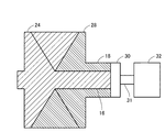
Classifications
-
- F—MECHANICAL ENGINEERING; LIGHTING; HEATING; WEAPONS; BLASTING
- F02—COMBUSTION ENGINES; HOT-GAS OR COMBUSTION-PRODUCT ENGINE PLANTS
- F02B—INTERNAL-COMBUSTION PISTON ENGINES; COMBUSTION ENGINES IN GENERAL
- F02B53/00—Internal-combustion aspects of rotary-piston or oscillating-piston engines
-
- Y—GENERAL TAGGING OF NEW TECHNOLOGICAL DEVELOPMENTS; GENERAL TAGGING OF CROSS-SECTIONAL TECHNOLOGIES SPANNING OVER SEVERAL SECTIONS OF THE IPC; TECHNICAL SUBJECTS COVERED BY FORMER USPC CROSS-REFERENCE ART COLLECTIONS [XRACs] AND DIGESTS
- Y02—TECHNOLOGIES OR APPLICATIONS FOR MITIGATION OR ADAPTATION AGAINST CLIMATE CHANGE
- Y02T—CLIMATE CHANGE MITIGATION TECHNOLOGIES RELATED TO TRANSPORTATION
- Y02T10/00—Road transport of goods or passengers
- Y02T10/10—Internal combustion engine [ICE] based vehicles
- Y02T10/12—Improving ICE efficiencies
Definitions
- the present invention relates to a power generation system using a rotating piston type engine.
- Patent Document 1 discloses a plurality of pistons that slide inside a cylindrical housing around a center axis of the housing as a rotation center. There is disclosed a configuration in which an output shaft is rotated by burning fuel in a combustion chamber provided and formed by an inner peripheral surface of a housing and a plurality of pistons rotatably sliding in the housing.
- the present invention has been made to solve the above-described problem, and an object of the present invention is to provide a simple configuration, capable of accurately controlling the rotational positions of a plurality of pistons that rotate and slide in a housing, An object of the present invention is to provide a power generation system using a rotary piston type engine that controls the rotation of a plurality of pistons that rotate and slide in a housing so that a predetermined combustion state occurs.
- a power generation system includes a housing, a first piston member rotatably supported in the housing, and a second piston member rotatably supported in the housing.
- a rotary piston type engine in which a combustion chamber for burning fuel is formed by the inner peripheral surface of the first piston member and the second piston member, a first rotary electric machine which is driven by the engine to generate power, and A second rotating electric machine is configured to generate electric power by being rotationally driven by the engine, and a control device for controlling the generated electric power of the first rotating electric machine and the generated electric power of the second rotating electric machine during operation of the engine.
- the first rotating electric machine is connected to the first piston member.
- the second rotating electric machine is connected to the second piston member.
- the control device controls the generated power of the first rotating electric machine when the first piston member rotates with the operation of the engine, and controls the generated power of the second rotating electric machine when the second piston member rotates.
- one of the first piston member and the second piston member rotates due to the combustion of the fuel in the combustion chamber.
- the rotational position of the first piston member can be controlled with high accuracy by controlling the power generated by the first rotating electric machine.
- the rotational position of the second piston member can be controlled with high accuracy by controlling the power generated by the second rotating electric machine.
- control device is configured to perform first control for adjusting the first rotation speed of the first piston member by increasing or decreasing regenerative torque generated in the first rotating electric machine during operation of the engine, and regeneration generated in the second rotating electric machine. And second control for adjusting the second rotational speed of the second piston member by increasing or decreasing the torque.
- the first rotational position of the first piston member is adjusted by increasing or decreasing the regenerative torque generated in the first rotating electric machine.
- the second rotational position of the second piston member is adjusted by increasing or decreasing the regenerative torque generated in the second rotating electric machine. Therefore, the rotational positions of the first piston member and the second piston member can be controlled with high accuracy.
- control device when one of the first piston member and the second piston member rotates due to combustion of the fuel in the combustion chamber during operation of the engine, the rotation speed of one of the first piston member and the second piston member is reduced.
- the value exceeds the upper limit, the regenerative torque of the rotating electric machine connected to one of them is increased as compared with when the value falls below the upper limit.
- control device when one of the first piston member and the second piston member rotates due to combustion of the fuel in the combustion chamber during operation of the engine, the rotation speed of one of the first piston member and the second piston member is reduced.
- the value is below the lower limit, the regenerative torque of the rotating electric machine connected to one of the two is reduced more than when the value exceeds the lower limit.
- control device is configured to control the rotation of the first piston member when one of the first piston member and the second piston member is rotated by combustion of the fuel in the combustion chamber during operation of the engine.
- the rotating electric machine connected to one of the other is controlled as the electric motor so that the rotational angle difference falls within the allowable range.
- the engine has a limiting device that limits the rotation direction of the first piston member and the second piston member to one direction.
- a first piston member and a second piston member provided to face each other in a housing having a cylindrical inner peripheral surface is provided to extend from the center of rotation toward the inner peripheral surface of the housing, and It has a main body configured to have its end abutting on the inner peripheral surface, and at least one piston piece provided on the outer peripheral surface of the main body.
- the piston piece of the first piston member extends toward the second piston member and is configured such that its end abuts on the inner peripheral surface of the second piston member and the housing.
- the piston piece of the second piston member extends toward the first piston member and is configured such that an end thereof abuts on the inner peripheral surface of the first piston member and the housing.
- any one of the first piston member and the second piston member can be rotated by the restriction device.
- a power generation system includes a housing, a first piston member rotatably supported in the housing, and a second piston member rotatably supported in the housing.
- a rotary piston type engine in which a combustion chamber for burning fuel is formed by the inner peripheral surface of the first piston member and the second piston member, and which is connected to the first piston member and the second piston member and functions as an electric motor
- a control device that controls the rotating electric machine, which includes one or more rotating electric machines that generate power by generating power and function as a generator.
- the control device causes the rotating electric machine to function as an electric motor, and performs a start control of bringing the first piston member and the second piston member close to each other to compress the gas in the combustion chamber.
- the first piston member and the second piston member are brought close to each other to compress the gas in the combustion chamber, thereby igniting the first piston member and the second piston member. Either the member or the second piston member can be rotated. Therefore, it is possible to control the rotation of the plurality of pistons that slide and rotate in the housing so that the engine enters a predetermined combustion state.
- control device controls the rotating electric machine such that the first piston member and the second piston member approach each other at a speed at which the engine can be ignited when starting of the engine is required.
- the fuel in the combustion chamber can be ignited by bringing the first piston member and the second piston member close to each other and compressing the gas in the combustion chamber. Therefore, one of the first piston member and the second piston member can be rotated by burning the fuel.
- the moving speed of the piston is low, the gas in the combustion chamber leaks from the seal portion of the piston, etc., so that ignition is not possible because the gas is not sufficiently compressed. it can. "The speed at which the ignition becomes possible" means the latter side.
- control device ignites the fuel in the combustion chamber at the first or several times of compression.
- the fuel in the combustion chamber is ignited at the first or several times of compression, so that the fuel is burned, so that either the first piston member or the second piston member can be rotated. Therefore, a predetermined combustion state can be quickly achieved when the engine is started.
- the control device controls the rotating electric machine such that the first piston member is at a first position, which is an initial starting position, before performing start control.
- the rotating electric machine is controlled such that the second piston member is at the second position, which is the initial starting position.
- the first piston member and the second piston member can be set to the first position and the second position, respectively. Therefore, it is possible to control the rotation of the plurality of pistons that rotate and slide in the housing so that the engine is brought into a predetermined combustion state when the engine is started.
- control device controls the rotary electric machine such that the first piston member is at a first position, which is an initial starting position, when the engine is stopped, and the second piston member is at a second position, which is an initial starting position.
- the rotating electric machine is controlled to be at the position of.
- the first piston member and the second piston member can be set to the first position and the second position, respectively. Therefore, it is possible to control the rotation of the plurality of pistons that rotate and slide in the housing so that the engine is brought into a predetermined combustion state when the engine is started.
- control device separates one of the first piston member and the second piston member from the other during the execution of the start control, when the rotation state of one of the first piston member and the second piston member is a collision state with the other. Rotate in the direction.
- control device determines whether the fuel has been ignited in the combustion chamber during the execution of the start control, and when it is determined that the fuel has not been ignited in the combustion chamber, the first piston member and The second piston member is brought closer to fire.
- control device controls the power generated by the rotating electric machine when at least one of the first piston member and the second piston member rotates with the operation of the engine.
- the rotational positions of a plurality of pistons that rotate and slide in the housing can be controlled with high accuracy, and when the engine is started, the pistons rotate and slide in the housing so that a predetermined combustion state is obtained. It is possible to provide a power generation system using a rotating piston type engine that controls the rotation of a plurality of pistons.
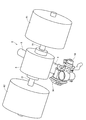
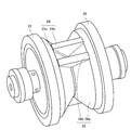
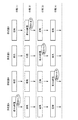
- FIG. 1 is a diagram illustrating an example of a schematic configuration of a power generation system according to an embodiment. It is a perspective view showing a part of composition of a power generation system. It is a figure showing an example of the composition of the piston member provided in the engine. It is a figure for explaining an example of operation of each component when fuel burns in combustion chamber A. It is a figure for explaining an example of operation of each component when fuel burns in combustion chamber D. It is a figure for explaining an example of a change of a stroke in each combustion chamber.
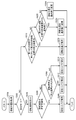
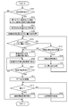
- 5 is a flowchart illustrating an example of a first process according to the first embodiment of the present invention, which is executed by the control device.
- FIG. 13 is a flowchart illustrating an example of a second process executed by the control device according to the second embodiment of the present invention. It is a figure showing the relation between regenerative torque and rotation speed. 4 is a timing chart showing an example of a change over time of a rotation speed and a regenerative torque.
- FIG. 9 is a diagram for explaining an example of an operation of the control device when a compression amount in a compression stroke is insufficient.
- FIG. 9 is a diagram for explaining an example of the operation of the control device when the amount of compression in the compression stroke is excessive.
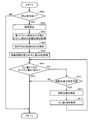
- 13 is a flowchart illustrating an example of a process according to a third embodiment of the present invention, which is executed by the control device.
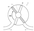
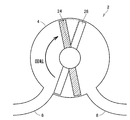
- FIG. 4 is a diagram for explaining an example of a positional relationship between a first piston member and a second piston member when the engine is started.
- FIG. 7 is a diagram for explaining an example of an operation of a first piston member at the time of starting the engine. It is a figure for explaining an example of operation of the 2nd piston member at the time of ignition. It is a figure for explaining an example of operation of a control device when a rotation position of the 1st piston member at the time of ignition shifts.
- 9 is a flowchart illustrating an example of a process performed by a control device according to a first modification. 13 is a flowchart illustrating an example of a process performed by a control device according to a second modification. 13 is a flowchart illustrating an example of a process performed by a control device according to a third modification. It is a figure showing an example of composition of a piston member in a modification.
- FIG. 1 is a diagram illustrating an example of a schematic configuration of a power generation system 1 according to the present embodiment.
- FIG. 2 is a perspective view showing a part of the configuration of the power generation system 1.
- a power generation system 1 includes a rotating piston engine (hereinafter simply referred to as an engine) 2, a first MG (Motor Generator) 61 as a first rotating electric machine, and a second rotating electric machine.
- the engine 2 is a rotary piston type internal combustion engine.
- fuel for the engine 2 for example, gas, gasoline, light oil, or the like is used.
- the engine 2 includes a housing 4, an intake pipe 6, an exhaust pipe 8, an injector 10, a throttle valve 12, a throttle motor 14, a first output shaft 16, and a second output shaft 18.
- One end of the intake pipe 6 is connected to an intake port (not shown) of the housing 4.
- An air cleaner (not shown) is connected to the other end of the intake pipe 6, for example.
- the air cleaner removes foreign matters from air taken in from outside the engine 2.
- the air sucked from the air cleaner flows through the intake pipe 6.
- the air flowing through the intake pipe 6 flows through the intake port of the housing 4.
- the throttle valve 12 is provided in the intake pipe 6 and restricts the flow rate of air flowing through the intake pipe 6.
- the opening of the throttle valve 12 (throttle opening) is adjusted by a throttle motor 14 that operates according to a control signal TH from the control device 200.
- the injector 10 is provided upstream of the throttle valve 12 of the intake pipe 6 and injects fuel (for example, gas) into the intake pipe 6 according to a control signal INJ from the control device 200.
- the injected fuel is mixed with air in the intake pipe 6 and flows to the intake port of the housing 4.
- the outer peripheral portion of the housing 4 is formed in a cylindrical shape as shown in FIG. 2, and the inner peripheral portion is also formed in a cylindrical shape.
- the housing 4 houses therein a first piston member connected to the first output shaft 16 and a second piston member connected to the second output shaft 18.
- One end of the exhaust pipe 8 is connected to an exhaust port (not shown) of the housing 4.
- An exhaust processing device (not shown) is connected to the other end of the exhaust pipe 8, for example.
- exhaust gas generated by combustion in the housing 4 flows from an exhaust port of the housing 4 to an exhaust pipe 8.
- the exhaust gas flowing through the exhaust pipe is purified by the exhaust treatment device and discharged to the outside of the engine 2.
- FIG. 3 is a diagram illustrating an example of a configuration of a piston member provided inside the engine.
- the first piston member 24 and the second piston member 28 are stored in the housing 4 in combination.
- the first piston member 24 includes a first rotator 24a as a main body and a first wall member 24b as a piston piece.
- the second piston member 28 includes a second rotator 28a as a main body and a second wall member 28b as a piston piece.
- the first rotator 24a and the second rotator 28a are rotatably supported by the housing 4 so that the rotation centers coincide with each other, and one end face of the first rotator 24a and one of the second rotators 28a are provided. It is provided so that an end surface may face.
- the first rotator 24a and the second rotator 28a are formed so as to have a slope portion in a cross section including the rotation center. Accordingly, in a state where the first rotator 24a and the second rotator 28a are combined, a concave portion having a V-shaped cross section is formed between the first rotator 24a and the second rotator 28a in the circumferential direction. Formed.
- the first rotator 24a is provided with a first wall member 24b extending from the center of rotation toward the inner peripheral surface of the housing 4 and having an end abutting on the inner peripheral surface of the housing 4.
- the first wall member 24b is configured by two triangular plate members.
- the two triangular plate members of the first wall member 24b are provided on the first rotating body 24a so as to be symmetrical with respect to the center of rotation.
- the second rotating body 28a is provided so as to extend from the center of rotation toward the inner peripheral surface of the housing 4 and has a second wall member 28b whose end abuts on the inner peripheral surface of the housing 4.
- the second wall member 28b is constituted by two triangular plate members having the same shape as the plate member constituting the first wall member 24b.
- the two triangular plate-shaped members of the second wall member 28b are provided on the second rotating body 28a so as to be symmetrical with respect to the center of rotation.
- Each of the triangular plate-like members of the first wall member 24b and the second wall member 28b has a first rotating body 24a and a second rotating member 24a in a state where the first piston member 24 and the second piston member 28 are housed in the housing 4. It is formed so as to conform to the triangular cross-sectional shape formed by the recess between the two rotating bodies 28a and the inner peripheral surface of the housing 4.
- the outer peripheral portions of the triangular plate members of the first wall member 24b and the second wall member 28b are configured to be slidable on the inner peripheral surface of the housing 4.
- the first output shaft 16 is connected to the first rotating body 24a such that the rotation centers coincide with each other.
- the second output shaft 18 is connected to the second rotating body 28a such that the rotation centers coincide with each other.
- one-way clutches 22, 26 as limiting devices are provided between each of the first rotating body 24a and the second rotating body 28a and the housing 4, for example.
- the one-way clutch 22 permits rotation only in a predetermined rotation direction within the housing 4 of the first rotating body 24a, and suppresses rotation in a direction opposite to the predetermined rotation direction.
- the one-way clutch 26 permits rotation only in a predetermined rotation direction in the housing 4 of the second rotating body 28a, and suppresses rotation in a direction opposite to the predetermined rotation direction.
- Both the first output shaft 16 and the second output shaft 18 rotate by the combustion of the fuel in the housing 4.
- First output shaft 16 is connected to a rotation shaft of first MG 61.
- Second output shaft 18 is connected to a rotation shaft of second MG 62. Further, the first output shaft 16 is rotatable by the torque of the first MG 61, and the second output shaft 18 is rotatable by the drive torque of the second MG 62.
- Each of the first MG 61 and the second MG 62 is a rotating electric machine that generates power by functioning as an electric motor and generates electric power by functioning as a generator.
- each of first MG 61 and second MG 62 is, for example, a three-phase AC rotating electric machine.
- Each of the first inverter 71 and the second inverter 72 is a power converter configured to be capable of converting power between DC power and AC power.
- First MG 61 is electrically connected to first inverter 71.
- the first inverter 71 is controlled by a control signal INV1 from the control device 200. That is, the power transmitted and received between first MG 61 and first inverter 71 is controlled by control signal INV 1 from control device 200.
- Control device 200 controls first inverter 71 such that regenerative torque is generated in first MG 61, for example. At this time, the regenerative power generated in first MG 61 is converted from AC power to DC power in first inverter 71 and supplied to battery 80. Battery 80 is charged by DC power supplied from first inverter 71. Alternatively, control device 200 controls first inverter 71 such that drive torque is generated in first MG 61. At this time, the power of battery 80 is converted from DC power to AC power in first inverter 71 and supplied to first MG 61.
- the second MG 62 is electrically connected to the second inverter 72.
- the second inverter 72 is controlled by a control signal INV2 from the control device 200. That is, the power transmitted and received between second MG 62 and second inverter 72 is controlled by control signal INV 2 from control device 200.
- Control device 200 controls second inverter 72 such that regenerative torque is generated in second MG 62, for example. At this time, the regenerative power generated in second MG 62 is converted from AC power to DC power in second inverter 72 and supplied to battery 80. Battery 80 is charged by DC power supplied from second inverter 72. Alternatively, control device 200 controls second inverter 72 such that drive torque is generated in second MG 62. At this time, the power of battery 80 is converted from DC power to AC power in second inverter 72 and supplied to second MG 62.
- Battery 80 is a DC power supply constituted by a secondary battery such as a nickel-metal hydride battery or a lithium ion battery.
- the battery 80 may be any power storage device that can store the DC power supplied from the first inverter 71 or the second inverter 72.
- a capacitor or the like may be used instead of the battery 80.
- the operation of the power generation system 1 is controlled by the control device 200.
- the control device 200 includes a CPU (Central Processing Unit) for performing various processes, a memory including a ROM (Read Only Memory) for storing programs and data, a RAM (Random Access Memory) for storing processing results of the CPU, and the like; An input / output port (both not shown) for exchanging information with the outside is included.
- the above-mentioned sensors for example, the first resolver 101 and the second resolver 102 are connected to the input port.
- Devices to be controlled for example, the engine 2, the first inverter 71, the second inverter 72, etc.
- the output port for example, the engine 2, the first inverter 71, the second inverter 72, etc.
- the control device 200 controls various devices such that the power generation system 1 is brought into a desired operation state based on signals from the sensors and the devices, and maps and programs stored in the memory. Note that the various controls are not limited to processing by software, but can be processed by dedicated hardware (electronic circuit).
- the first resolver 101 detects the rotation angle of the rotation shaft (first output shaft 16) of the first MG 61 (hereinafter, referred to as rotation angle CA1).
- the first resolver 101 transmits a signal indicating the detected rotation angle CA1 to the control device 200.
- the second resolver 102 detects the rotation angle of the rotation shaft (second output shaft 18) of the second MG 62 (hereinafter, referred to as rotation angle CA2).
- the second resolver 102 transmits a signal indicating the detected rotation angle CA2 to the control device 200.
- FIG. 4 is a view for explaining an example of the operation of each component when fuel is burned in the combustion chamber A.
- FIG. 5 is a diagram for explaining an example of the operation of each component when fuel is burned in the combustion chamber D.
- FIG. 4 shows a cross section of a central portion of the housing 4 (for example, a contact portion between the first rotating body 24a and the second rotating body 28a).
- a central portion of the housing 4 for example, a contact portion between the first rotating body 24a and the second rotating body 28a.
- four combustion chambers A to D are formed by the inner peripheral surface of the housing 4, the first piston member 24, and the second piston member 28.
- the one-way clutches 22 and 26 suppress the counterclockwise rotation of the first piston member 24 and the second piston member 28 and allow the clockwise rotation.
- the expanded exhaust gas is discharged from the exhaust pipe 8 in the exhaust stroke. That is, when the second piston member 28 rotates in the direction of the dashed arrow due to the combustion of fuel in the combustion chamber A, the rotation position of the first piston member 24 is maintained, and the volume of the combustion chamber B decreases. At this time, the combustion chamber B is in communication with the exhaust pipe 8. Therefore, the exhaust gas in the combustion chamber B is discharged to the exhaust pipe 8 as the volume of the combustion chamber B decreases.
- the intake stroke in which a mixture of air and fuel is sucked from the intake pipe 6. That is, when the second piston member 28 rotates in the direction of the dashed arrow due to the combustion of the fuel in the combustion chamber A, the rotation position of the first piston member 24 is maintained, and the volume of the combustion chamber C increases. At this time, the combustion chamber C communicates with the intake pipe 6 while the second piston member 28 rotates in the direction of the dashed arrow. Therefore, the air-fuel mixture is drawn into the combustion chamber C from the intake pipe 6 as the volume of the combustion chamber C increases.
- the air-fuel mixture sucked from the intake pipe 6 is compressed. That is, when the second piston member 28 rotates in the direction of the dashed arrow due to the combustion of fuel in the combustion chamber A, the rotation position of the first piston member 24 is maintained, and the volume of the combustion chamber D decreases. At this time, since the combustion chamber D does not communicate with either the intake pipe 6 or the exhaust pipe 8, the mixture in the combustion chamber D is compressed due to the decrease in the volume of the combustion chamber D.
- FIG. 5 shows a cross section of the central portion of the housing 4 as in FIG.
- the configuration of the engine 2 shown in FIG. 5 is different from the configuration of the engine 2 shown in FIG. 4 in the positional relationship between the first piston member 24 and the second piston member 28 and the positions and volumes of the combustion chambers A to D. Is the same except for the difference.
- the expansion stroke follows the compression stroke. That is, in the combustion chamber D, the mixture of the compressed air and the fuel is ignited by self-ignition.
- the counterclockwise movement of the second piston member 28 is suppressed by the one-way clutch 26, so that only the first piston member 24 is maintained while the rotational position of the second piston member 28 is maintained.
- the volume of the combustion chamber D increases with the expansion of the gas in the rotor and the combustion chamber D clockwise.
- the exhaust stroke follows the expansion stroke. That is, when the first piston member 24 rotates clockwise due to the combustion of the fuel in the combustion chamber D, the rotational position of the second piston member 28 is maintained, and the volume of the combustion chamber A decreases. At this time, the combustion chamber A is in communication with the exhaust pipe 8. Therefore, the exhaust gas in the combustion chamber A is discharged to the exhaust pipe 8 as the volume of the combustion chamber A decreases.
- the intake stroke follows the exhaust stroke. That is, when the first piston member 24 rotates clockwise due to the combustion of fuel in the combustion chamber D, the rotational position of the second piston member 28 is maintained, and the volume of the combustion chamber B increases. At this time, the combustion chamber B communicates with the intake pipe 6 while the first piston member 24 is rotating. Therefore, the air-fuel mixture is sucked into the combustion chamber B from the intake pipe 6 as the volume of the combustion chamber B increases.
- the compression stroke follows the intake stroke. That is, when the first piston member 24 rotates clockwise due to the combustion of the fuel in the combustion chamber D, the rotational position of the second piston member 28 is maintained, and the volume of the combustion chamber C decreases. At this time, since the combustion chamber C is not in communication with either the intake pipe 6 or the exhaust pipe 8, the mixture in the combustion chamber C is compressed by the reduction in the volume of the combustion chamber C.
- the engine 2 operates by alternately rotating the first piston member 24 and the second piston member 28 every time combustion is performed in any of the combustion chambers A to D.
- the rotation of the second piston member 28 when the fuel is burned in the combustion chamber A or the combustion chamber C, the rotation of the second piston member 28 while the second piston member 28 rotates to a predetermined rotation position. Is generated in the second MG 62 by generating regenerative torque for braking the motor.
- the rotation of the first piston member 24 is stopped while the first piston member 24 rotates to a predetermined rotation position. Electric power is generated by generating regenerative torque for braking in the first MG 61.
- first piston member 24 and the second piston member 28 rotate alternately to generate power in the first MG 61 and the second MG 62, and the generated AC power is converted to DC power in the first inverter 71 and the second inverter 72. It is converted and supplied to the battery 80.
- FIG. 6 is a diagram for explaining an example of a change in the stroke in each combustion chamber.
- the combustion chamber A becomes an expansion stroke
- the combustion chamber B becomes an exhaust stroke
- the combustion chamber C becomes an intake stroke
- the combustion chamber D becomes a compression stroke.
- the positional relationship between the first piston member 24 and the second piston member 28 is as shown in FIG. Therefore, in the stroke (1), the second piston member 28 rotates by the combustion in the combustion chamber A, and a regenerative torque is generated in the second MG 62.
- the combustion chamber A becomes an exhaust stroke
- the combustion chamber B becomes an intake stroke
- the combustion chamber C becomes a compression stroke
- the combustion chamber D becomes an expansion stroke.
- the positional relationship between the first piston member 24 and the second piston member 28 is as shown in FIG. Therefore, in the stroke (2), the first piston member 24 is rotated by the combustion in the combustion chamber D, and the regenerative torque is generated in the first MG 61.
- the combustion chamber A becomes the intake stroke
- the combustion chamber B becomes the compression stroke
- the combustion chamber C becomes the expansion stroke
- the combustion chamber D becomes the exhaust stroke.
- the positional relationship between the first piston member 24 and the second piston member 28 is as shown in FIG. Therefore, in the stroke (3), the second piston member 28 is rotated by combustion in the combustion chamber C, and a regenerative torque is generated in the second MG 62.
- the combustion chamber A becomes a compression stroke
- the combustion chamber B becomes an expansion stroke
- the combustion chamber C becomes an exhaust stroke
- the combustion chamber D becomes an intake stroke.
- the positional relationship between the first piston member 24 and the second piston member 28 is as shown in FIG. Therefore, in the stroke (4), the first piston member 24 is rotated by the combustion in the combustion chamber B, and a regenerative torque is generated in the first MG 61.
- the expansion stroke, the exhaust stroke, the intake stroke, and the compression stroke are appropriately performed.
- the configuration of the engine becomes complicated, only the manufacturing cost and the number of parts increase. Instead, the durability of the engine may decrease.
- the configuration of engine 2 is set to the above-described configuration, and control device 200 controls the first engine by increasing or decreasing the regenerative torque generated in first MG 61 during operation of engine 2.
- the first control for adjusting the rotation speed Nm1 of the piston member 24 and the second control for adjusting the rotation speed Nm2 of the second piston member 28 by increasing or decreasing the regenerative torque generated in the second MG 62 are selectively executed. .
- the rotational positions of the first piston member 24 and the second piston member 28 can be controlled with high accuracy, and the combustion of the engine 2 can be stabilized. Further, since it is not necessary to separately add a new mechanism, parts, or the like to perform these controls, the configuration of the engine 2 can be simplified. Therefore, it is possible to suppress an increase in the manufacturing cost and the number of parts and to suppress a decrease in durability.
- FIG. 7 is a flowchart illustrating an example of the first process executed by the control device 200.
- FIG. 8 is a flowchart illustrating an example of the second process performed by the control device 200.
- the processes shown in these flowcharts are called from a main routine (not shown) and executed at predetermined control cycles.
- the first process is a process in which the first MG 61 is to be controlled
- the second process is a process in which the second MG 62 is to be controlled.
- the control device 200 operates the engine 2 by executing the first processing and the second processing in parallel.
- step (hereinafter, step is referred to as S) 100 control device 200 obtains the rotation position (rotation angle CA1) of first MG 61 and the rotation position (rotation angle CA2) of second MG 62. I do. Control device 200 acquires the rotation position of first MG 61 and the rotation position of second MG 62 using first resolver 101 and second resolver 102, for example.
- control device 200 determines whether or not the control mode of first MG 61 is a regenerative mode (a control mode for generating regenerative torque in first MG 61).
- the control device 200 determines, for example, that the rotational position of the first piston member 24 and the rotational position of the second piston member 28 correspond to the above-described stroke (2) or stroke (4) (the first piston member shown in FIG. 5). If it is within a predetermined range based on the rotation position of the second piston member 28), it is determined that the control mode of the first MG 61 is the regeneration mode. When it is determined that the control mode of first MG 61 is the regeneration mode (YES in S102), the process proceeds to S104.
- control device 200 calculates the rotation speed of first MG 61.
- Control device 200 calculates the amount of change in rotation angle CA1 of first MG 61 during the immediately preceding predetermined period as rotation speed Nm1 of first MG 61.
- control device 200 determines whether or not rotation speed Nm1 of first MG 61 is within a predetermined range.
- Control device 200 acquires, for example, a reference value of rotation speed Nm1 of first MG 61 corresponding to the current rotation position of first piston member 24 (that is, rotation angle CA1 of MG 61). It is determined whether or not the value is within a predetermined range centered on the reference value. Control device 200 determines the rotation speed of first MG 61 from rotation position of first MG 61 from the rotation position of first piston member 24 using a map indicating the relationship between the rotation position of first piston member 24 and the reference value of rotation speed Nm1 of first MG 61, for example. Get the reference value.
- the map indicating the relationship between the rotational position of first piston member 24 and the reference value of the rotational speed of first MG 61 is adapted, for example, by experiments, and is created in advance and stored in the memory of control device 200. If it is determined that rotation speed Nm1 of first MG 61 is within the predetermined range (YES in S106), the process proceeds to S108.
- control device 200 maintains the regenerative torque generated in first MG 61 at the initial value.
- Control device 200 determines the regenerative torque based on rotation speed Nm1 of first MG 61.
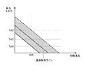
- FIG. 9 is a diagram illustrating a relationship between the regenerative torque and the rotation speed. 9 indicates a reference control line, and indicates an initial value of the regenerative torque set for the rotation speed Nm1 of the first MG 61.
- the broken line in FIG. 9 indicates the upper limit line of the adjustment range of the regenerative brake amount (the range of the hatched portion in FIG. 9).
- the solid line in FIG. 9 indicates the lower limit line of the regenerative brake amount adjustment range.
- control device 200 sets Tq (1) as an initial value of the regenerative torque, and sets the first regenerative torque so that the set regenerative torque is generated.
- the inverter 71 is controlled.
- control device 200 determines whether or not rotation speed Nm1 of first MG 61 is higher than a predetermined range. Control device 200 determines that rotation speed Nm1 of first MG 61 is higher than the predetermined range, for example, when rotation speed Nm1 of first MG 61 is higher than the upper limit of the predetermined range. If it is determined that rotation speed Nm1 of first MG 61 is higher than the predetermined range (YES in S110), the process proceeds to S112.
- control device 200 increases the regenerative torque of first MG 61.
- Control device 200 increases the regenerative torque from an initial value. As shown in FIG. 9, for example, when rotation speed Nm1 of first MG 61 is N (0), control device 200 sets upper limit Tq (2) as the regenerative torque, and sets regenerative torque to The first inverter 71 is controlled so as to generate the signal.
- control device 200 decreases the regenerative torque.
- Control device 200 reduces the regenerative torque from the initial value. As shown in FIG. 9, for example, when rotation speed Nm1 of first MG 61 is N (0), control device 200 sets lower limit value Tq (0) as the regenerative torque, and the set regenerative torque is The first inverter 71 is controlled so as to generate the signal.
- control device 200 determines whether or not the rotation position of first MG 61 with respect to the rotation position of second MG 62 is within a predetermined range. That is, the control device 200 determines whether or not the rotation angle difference between the first piston member 24 and the second piston member 28 is within a predetermined range.
- Control device 200 acquires, for example, a reference value of the rotation position of first MG 61 corresponding to the rotation position of second MG 62, and determines whether or not the rotation position of first MG 61 is within a predetermined range around the reference value. .
- Control device 200 acquires a reference value of the rotation position of first MG 61 from the rotation position of second MG 62 using, for example, a map indicating the relationship between the rotation position of second MG 62 and the reference value of the rotation position of first MG 61.
- the map indicating the relationship between the rotation position of the second MG 62 and the reference value of the rotation position of the first MG 61 is adapted by, for example, experiments, created in advance, and stored in the memory of the control device 200.
- control device 200 maintains the rotational position of first MG 61. If it is determined in S116 that the rotation position of first MG 61 with respect to the rotation position of second MG 62 is outside the predetermined range (NO in S116), the process proceeds to S120.
- control device 200 determines that the rotational position of first MG 61 is a rotational position on the advance side of a predetermined range (for example, a rotational position advanced in a clockwise direction in the state of engine 2 shown in FIG. 4). It is determined whether or not. If it is determined that the rotation position of first MG 61 is a rotation position on the advance side of the predetermined range (YES in S120), the process proceeds to S122.
- a predetermined range for example, a rotational position advanced in a clockwise direction in the state of engine 2 shown in FIG. 4
- control device 200 changes the rotational position of first MG 61 after the next stroke to the rotational position on the retard side (for example, it has advanced in the counterclockwise direction in the state of engine 2 shown in FIG. 4). Change to rotational position). Control device 200 determines the difference between rotation angle CA2 of second MG 62 and rotation angle CA1 of first MG 61 after the next stroke by delaying a change in the rotation position of first MG 61, for example, by generating regenerative torque in first MG 61. The rotational position of first MG 61 may be changed so as to fall within the range.
- control device 200 changes the rotational position of first MG 61 after the next stroke to a rotational position on the advance side (for example, to a rotational position advanced in the clockwise direction in FIG. 4).
- Control device 200 changes the rotational position of first MG 61 to the advance side by, for example, generating a driving torque in first MG 61 to thereby rotate angle MG2 of second MG 62 and rotational angle CA1 of first MG 61 in the next stroke and thereafter.
- the rotation position of first MG 61 may be changed such that the difference between the first and second MGs is within a predetermined range.
- Control device 200 may change the rotation position of first MG 61 to a rotation position on the advance side when it is determined that the rotation position of first MG 61 is not on the advance side of the predetermined range.
- control device 200 acquires the rotational position of first MG 61 and the rotational position of second MG 62.
- control device 200 determines whether or not the control mode of second MG 62 is the regenerative mode. Control device 200 determines, for example, that the rotational position of first piston member 24 and the rotational position of second piston member 28 correspond to the above-described stroke (1) or stroke (3) (the first piston member shown in FIG. 4). If it is within a predetermined range with reference to (the rotational position of the second piston member 28 and the rotational position of the second piston member 28), it is determined that the control mode of the second MG 62 is the regeneration mode.
- control device 200 calculates rotation speed Nm2 of second MG 62.
- control device 200 determines whether or not rotation speed Nm2 of second MG 62 is within a predetermined range.
- Control device 200 obtains, for example, a reference value of rotation speed Nm2 of second MG 62 corresponding to the current rotation position of first piston member 24, and rotation speed Nm2 of second MG 62 falls within a predetermined range around the reference value as a center value. Is determined. If it is determined that rotation speed Nm2 of second MG 62 is within the predetermined range (YES in S206), the process proceeds to S208.
- control device 200 maintains the regenerative torque generated in second MG 62 at the initial value. If it is determined that rotation speed Nm2 of second MG 62 is outside the predetermined range (NO in S206), the process proceeds to S210.
- control device 200 determines whether or not rotation speed Nm2 of second MG 62 is higher than a predetermined range. When it is determined that rotation speed Nm2 of second MG 62 is higher than the predetermined range (YES in S210), the process proceeds to S212.
- control device 200 increases the regenerative torque of second MG 62. Since the control mode of the increase in the regenerative torque is as described in the processing of S112, the detailed description will not be repeated.
- control device 200 decreases the regenerative torque. Since the control mode of the decrease in the regenerative torque is as described in the processing of S114, the detailed description will not be repeated.
- control device 200 determines whether or not the rotation position of second MG 62 with respect to the rotation position of first MG 61 is within a predetermined range. When it is determined that the rotation position of second MG 62 with respect to the rotation position of first MG 61 is within a predetermined range (YES in S216), the process proceeds to S218.
- control device 200 maintains the rotational position of second MG 62. If it is determined in S216 that the rotational position of second MG 62 with respect to the rotational position of first MG 61 is outside the predetermined range (NO in S216), the process proceeds to S220.
- control device 200 determines whether or not the rotational position of second MG 62 is a rotational position on the advance side of a predetermined range. If it is determined that the rotation position of second MG 62 is on the advance side of the predetermined range (YES in S220), the process proceeds to S222.
- control device 200 changes the rotational position of second MG 62 after the next stroke to the rotational position on the retard side.
- the process proceeds to S224.
- control device 200 changes the rotational position of second MG 62 after the next stroke to the rotational position on the advance side.
- control device 200 The operation of the control device 200 based on the above structure and flowchart will be described with reference to FIGS.
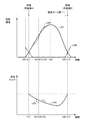
- FIG. 10 is a timing chart showing an example of a temporal change of the rotation speed and the regenerative torque.
- the vertical axis of the upper graph in FIG. 10 indicates the rotation speed.
- the vertical axis of the lower graph in FIG. 10 indicates the regenerative torque.
- the horizontal axis of the upper and lower graphs in FIG. 10 indicates time.
- LLN1 (solid line) and LN4 (dashed line) in FIG. 10 indicate changes in the rotation speed Nm2 of the second MG 62.
- LN2 (dashed-dotted line) in FIG. 10 indicates a change in the rotation speed Nm1 of the first MG 61.
- LN3 (solid line) and LN5 (dashed line) in FIG. 7 indicate changes in the regenerative torque generated in second MG 62.
- first piston member 24 and second piston member 28 becomes the positional relationship shown in FIG. 4 corresponding to stroke (1), and combustion chamber A becomes the expansion stroke. Assume the case.
- the stopped second piston member 28 starts rotating and sliding due to the pressure increase due to the rotation of the first piston member 24 in the combustion chamber A, and at time t (0), the combustion starts.
- the first piston member 24 is stopped by the one-way clutch 22 as shown by LN2 in FIG. 10, and the rotation speed Nm2 of the second piston member 28 increases.
- the second inverter 72 is controlled so as to generate a regenerative torque corresponding to the rotation speed Nm2 of the second MG 62 as indicated by LN3 in FIG.
- second inverter 72 is controlled such that rotation speed Nm2 increases and regenerative torque decreases.
- the first process and the second process are executed in parallel. That is, the rotation position of the first MG 61 and the rotation position of the second MG 62 are acquired by performing the first processing and the second processing (S100, S200).
- first process since the control mode of first MG 61 is not the regeneration mode (NO in S102), it is determined whether the rotational position of first MG 61 with respect to the rotational position of second MG 62 is within a predetermined range (S116). . When the rotation position of first MG 61 with respect to the rotation position of second MG 62 is within a predetermined range (YES in S116), the rotation position of first MG 61 is maintained (S118).
- first piston member 24 in the stopped state starts rotating and sliding due to the pressure increase due to the rotation of the second piston member 28 in the combustion chamber D, and at time t (7), the combustion starts.
- the second piston member 28 is stopped by the one-way clutch 26, and the rotation speed Nm1 of the first piston member 24 increases.
- first inverter 71 is controlled such that a regenerative torque corresponding to rotation speed Nm1 of first MG 61 is generated.
- control device 200 when the amount of compression in the compression stroke is excessive or insufficient will be described with reference to FIGS.
- FIG. 11 is a diagram for explaining an example of the operation of the control device 200 when the amount of compression in the compression stroke is insufficient.
- the positional relationship between the first piston member 24 and the second piston member 28 becomes a positional relationship corresponding to the stroke (1), and the combustion chamber A is compressed immediately before. Assume that the compression amount is insufficient during the stroke.
- the rotational position of the first MG 61 and the rotational position of the second MG 62 are acquired (S100). Since the control mode of the first MG 61 is not the regeneration mode (NO in S102), the rotational position of the second MG 62 It is determined whether the rotational position of first MG 61 is within a predetermined range (S116).
- the rotation position of first MG 61 is a rotation position on the retard side of the predetermined range (S120). NO), the rotational position of the first MG 61 after the next stroke is changed to the rotational position on the advance side (S124).
- FIG. 12 is a diagram for explaining an example of the operation of control device 200 when the amount of compression in the compression stroke is excessive.
- the positional relationship between the first piston member 24 and the second piston member 28 becomes a positional relationship corresponding to the stroke (1), and the combustion chamber A is compressed immediately before. It is assumed that the compression amount is excessive during the stroke.
- the rotational position of the first MG 61 and the rotational position of the second MG 62 are acquired (S100). Since the control mode of the first MG 61 is not the regeneration mode (NO in S102), the rotational position of the second MG 62 It is determined whether the rotational position of first MG 61 is within a predetermined range (S116).
- the rotation position of first MG 61 is a rotation position on the advance side of the predetermined range (S120). YES), the rotational position of first MG 61 after the next stroke is changed to the rotational position on the retard side (S122).
- one of the first piston member 24 and the second piston member 28 rotates due to the combustion of fuel in the combustion chamber of the engine 2. Will do.
- the rotational position of the first piston member 24 can be controlled with high accuracy by controlling the electric power generated in the first MG 61.
- the rotational position of the second piston member 28 can be controlled with high precision by controlling the electric power generated in the second MG 62.
- the configuration of the engine can be simplified. Therefore, it is possible to suppress an increase in the manufacturing cost and the number of parts and to suppress a decrease in durability. Therefore, it is possible to provide a power generation system using a rotary piston type engine that can control the rotational positions of a plurality of pistons that rotate and slide in the housing with high accuracy with a simple configuration.
- the second control for adjusting the rotation speed Nm2 of the step S28 is selectively executed. Therefore, when the first piston member 24 rotates, the rotational position of the first piston member 24 is adjusted by increasing or decreasing the regenerative torque generated in the first MG 61. Further, when the second piston member 28 rotates during the operation of the engine 2, the rotational position of the second piston member 28 is adjusted by increasing or decreasing the regenerative torque generated in the second MG 62. Therefore, the rotational positions of the first piston member 24 and the second piston member 28 can be controlled with high accuracy.
- the rotation speed of one of the first piston member 24 and the second piston member 28 becomes the upper limit value.
- the regenerative torque of the rotating electric machine connected to either one is increased as compared with when it falls below the upper limit. Therefore, one of the rotation speeds can be reduced. Thereby, the rotational positions of the first piston member 24 and the second piston member 28 can be controlled with high accuracy.
- the rotational position of the first piston member 24 When the rotation angle difference between the rotation position of the second piston member 28 and the second piston member 28 is out of the allowable range, the rotating electric machine connected to one of the other is controlled so that the rotation angle difference is within the allowable range. Therefore, the rotational positions of the first piston member and the second piston member can be controlled with high accuracy.
- the combustion chamber is made ignitable by rotating a plurality of pistons using a starter motor.
- the predetermined combustion state cannot be quickly achieved.
- control device 200 causes first MG 61 or second MG 62 to function as an electric motor when starting of engine 2 is required, and causes first MG 24 and second MG 28 And the start control for compressing the gas in the combustion chamber is executed.
- the first piston member 24 and the second piston member 28 are brought close to each other to compress the gas in the combustion chamber, thereby igniting the fuel.
- One of the first piston member 24 and the second piston member 28 can be rotated. Therefore, the rotation of the first piston member 24 and the second piston member 28 that rotate and slide in the housing 4 can be controlled so that the engine 2 enters a predetermined combustion state.
- a power generation system that executes start control of engine 2 by first MG 61, second MG 62, and control device 200 is realized.
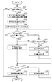
- FIG. 13 is a flowchart illustrating an example of a process performed by the control device 200.
- the process shown in this flowchart is called from a main routine (not shown) and executed at predetermined control cycles. The same applies to the processing shown in other flowcharts described later.
- step (hereinafter, step is referred to as S) 300 control device 200 determines whether or not there is a command to start engine 2.
- Control device 200 detects, for example, that engine 2 is in a stopped state and that a start operation of engine 2 (for example, pressing a start button) by a user is performed using a sensor, a switch, or the like. In this case, it is determined that there is a start command. If it is determined that there is a start command (YES in S300), the process proceeds to S302.
- control device 200 acquires the rotational position of first piston member 24 and the rotational position of second piston member 28.
- the control device 200 acquires the rotation position of the first piston member 24 using the detection result of the first resolver 101 and acquires the rotation position of the second piston member 28 using the detection result of the second resolver 102, for example. I do.
- control device 200 specifies the preceding MG and the following MG.
- the preceding MG is an MG that is connected to the piston member on the rotation direction side in the combustion chamber in which fuel burns first among the four combustion chambers when the engine 2 is started.
- the trailing MG is an MG connected to a piston member on the opposite side to the rotation direction in a combustion chamber in which fuel first burns out of the four combustion chambers when the engine 2 is started.
- FIG. 14 is a view for explaining an example of the positional relationship between the first piston member 24 and the second piston member 28 when the engine 2 is started.
- the second MG 62 is specified as the preceding MG
- the first MG 61 is determined as the trailing MG. Specified.
- control device 200 determines the magnitude of the difference between the actual rotation position of first piston member 24 and the initial starting position of first piston member 24 (hereinafter, referred to as deviation amount A). To get). Similarly, control device 200 obtains the magnitude of the difference between the actual rotational position of second piston member 28 and the initial starting position of second piston member 28 (hereinafter, referred to as deviation B).
- the initial starting position of the first piston member 24 and the initial starting position of the second piston member 28 are respectively shown in FIG.
- the rotation position of the first piston member 24 and the rotation position of the second piston member 28 are shown.
- the initial starting position of the first piston member 24 and the initial starting position of the second piston member 28 are respectively shown in FIG.
- the rotation position of the second piston member 28 and the rotation position of the first piston member 24 are determined.
- the initial start position of the first piston member 24 and the initial start position of the second piston member 28 are, for example, such that when the engine 2 starts, the combustion chamber in which fuel first burns out of the four combustion chambers does not communicate with the intake pipe 6. It is set as follows.
- control device 200 determines whether deviation amount A is smaller than threshold value A (0) and deviation amount B is smaller than threshold value B (0).
- threshold value A (0) may be the same value as threshold value B (0) or may be a different value.
- the threshold value A (0) and the threshold value B (0) are, for example, a rotational position where the rotational position of the first piston member 24 and a rotational position of the second piston member 28 do not affect the startability of the engine 2. It is a value for determining that the condition is true, and is a predetermined value.
- the rotational position that does not affect the startability of the engine 2 is, for example, a rotational position in which a combustion chamber in which fuel first burns when the engine 2 is started does not communicate with the intake pipe 6.
- control device 200 executes compression control by the trailing MG. Specifically, control device 200 executes, as compression control, control for rotating MG specified as the trailing MG at a predetermined rotation speed.
- the rotation speed at the time of executing the compression control of the MG specified as the trailing MG will be described as being the upper limit rotation speed.
- the rotation speed may be any rotation speed at which compression can be performed until ignition is possible. It is not limited to speed.
- control device 200 determines whether or not ignition has occurred in the combustion chamber. Control device 200 determines that ignition has occurred in the combustion chamber, for example, when the rotation speed of the piston member connected to the preceding MG exceeds a threshold value. The control device 200 can acquire the rotation speed of the piston member connected to the preceding MG using, for example, the first resolver 101 or the second resolver 102. If it is determined that ignition has occurred in the combustion chamber (YES in S312), the process proceeds to S314.
- control device 200 executes continuous operation control. Specifically, as described with reference to FIG. 6, control device 200 operates engine 2, first MG 61 and second MG 62 by repeating steps (1) to (4) in combustion chambers A to D. .
- the process proceeds to S316.
- control device 200 determines whether or not the rotational position of at least one of first piston member 24 and second piston member 28 can be corrected.
- the control device 200 determines that the rotational position of one piston member 24 can be corrected.
- control device 200 determines, for example, when the actual rotational position of the second piston member 28 is deviated from the initial start position in a direction opposite to a predetermined rotational direction that can be rotated by the one-way clutch 26. Determines that the rotational position of the second piston member 28 can be corrected.
- control device 200 corrects the rotational position. For example, when it is determined that shift amount A is equal to or greater than threshold value A (0) and that the rotational position of first piston member 24 can be corrected, control device 200 determines whether the first piston The first MG 61 is controlled such that the member 24 is at the starting initial position. Further, for example, when it is determined that displacement amount B is equal to or greater than threshold value B (0) and that the rotational position of second piston member 28 can be corrected, The second MG 62 is controlled such that the two-piston member 28 is at the starting initial position.
- control device 200 obtains deviation amounts A and B. Since the acquisition method is as described in S306 above, the detailed description thereof will not be repeated. Control device 200 then returns the process to S308.
- control device 200 continues the compression control, and returns the process to S312.
- control device 200 The operation of the control device 200 based on the above structure and flowchart will be described with reference to FIGS.
- FIG. 15 is a view for explaining an example of the operation of the first piston member 24 when the engine 2 is started.
- FIG. 16 is a view for explaining an example of the operation of the second piston member 28 at the time of ignition.
- FIG. 17 is a diagram for explaining an example of the operation of the control device 200 when the rotational position of the first piston member 24 shifts at the time of ignition.
- the deviation amounts A and B between the first piston member 24 and the second piston member 28 and each starting initial position are acquired (S306), and the acquired deviation amount A is smaller than the threshold value A (0), and When it is determined that displacement amount B is smaller than threshold value B (0) (YES in S308), compression control is performed by first MG 61 that is the trailing MG (S310). That is, by controlling the first inverter 71 so that the rotation shaft of the first MG 61 rotates, the first piston member 24 rotates as indicated by the arrow in FIG.
- the rotational position of the first piston member 24 is in a predetermined rotational direction (clockwise direction in the engine 2 shown in FIG. 15) from the rotational position of the first piston member 24 shown in FIG.
- the pressure in the combustion chamber increases due to the compression of the volume of gas in the combustion chamber.
- the pressure in the combustion chamber is lower than the pressure at which ignition becomes possible, ignition is not performed (NO in S312), and compression control is continued (S322).
- the gas in the combustion chamber may not ignite even at the rotational position of the first piston member 24 shown in FIG. 16 (NO in S312).
- the compression control is continued (NO in S312).
- FIG. 17 when the rotational position of the first piston member 24 further rotates in a predetermined rotational direction than the rotational position of the first piston member 24 shown in FIG.
- the gas in the combustion chamber is ignited by being compressed until it becomes ignitable (YES in S312), and the continuous operation control is executed (S314).
- first piston member 24 and the rotational position of second piston member 28 are acquired (S302), and second MG 62 is specified as the preceding MG and the second MG 62 is identified. It is assumed that 1MG61 is specified as the trailing MG (S304).
- the first piston member 24 and the second piston member 28 Is brought close to compress the gas in the combustion chamber, so that any one of the first piston member 24 and the second piston member 28 can be rotated by burning the fuel. Therefore, it is possible to control the rotation of the plurality of pistons that rotate and slide in the housing so that the engine 2 enters a predetermined combustion state. Therefore, it is possible to provide a power generation system that executes a start control of a rotary piston engine that controls the rotation of a plurality of pistons that rotate and slide in the housing so that a predetermined combustion state is obtained at the time of start.
- the first MG 61 or the second MG 62 is controlled such that the first piston member 24 and the second piston member 28 approach each other at a speed at which ignition is possible.
- the first piston member 24 and the second piston member 28 can be rotated.
- the moving speed of the piston is low, the gas in the combustion chamber leaks from the seal portion of the piston, etc., so that ignition is not possible because the gas is not sufficiently compressed. it can.
- the speed at which the ignition becomes possible means the latter side.
- the first MG 61 is controlled such that the first piston member 24 is at the start initial position.
- the second MG 62 is controlled such that the second piston member 28 is at the starting initial position. Therefore, it is possible to control the rotation of the plurality of pistons that rotate and slide in the housing so that the engine 2 enters a predetermined combustion state.
- the first piston member 24 and the second piston member 28 are compressed by bringing the first piston member 24 and the second piston member 28 closer by continuing the compression control. It is possible to reliably ignite.
- the fuel in the combustion chamber is ignited at the time of the first compression, so that one of the first piston member 24 and the second piston member 28 is rotated by burning the fuel. be able to. Therefore, a predetermined combustion state can be quickly achieved when the engine is started.
- control device 200 uses the power generated by the motor generator connected to the rotated piston member when at least one of first piston member 24 and second piston member 28 rotates with the operation of engine 2. Control. Thus, power can be generated using the motor generator connected to the piston member.
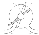
- the case where the number of the piston members provided in the housing 4 is two has been described as an example.
- the number of the piston members provided in the housing 4 may be three or more.
- the fuel may be burned in any one of the plurality of combustion chambers formed in the housing, or the fuel may be burned in the plurality of combustion chambers.
- the rotation cross section of the concave portion between the first rotating body 24a and the second rotating body 28a has a triangular shape
- both the first piston member 24 and the second piston member 28 have a triangular plate.
- the shape member is described as being provided as the first wall member 24b and the second wall member 28b, the shape of the rotation cross section of the recess and the shapes of the first wall member 24b and the second wall member 28b are limited to triangles. For example, it may be square, semicircular, or fan-shaped.
- the injector 10 has been described as injecting fuel into the intake pipe 6, but may be configured to directly inject fuel into the combustion chamber of the compression stroke in the housing 4, for example.
- control device 200 has been described as controlling the first inverter 71, the second inverter 72, the throttle motor 14, and the injector 10, but these electric devices are controlled using a plurality of control devices. It may be controlled.
- control device 200 divides these electrical devices into a first control device that controls first inverter 71 and second inverter 72 and a second control device that controls throttle motor 14 and injector 10. It may be controlled.
- the fuel in the combustion chamber is ignited at the first compression by continuing the compression control when the fuel is not ignited.
- the fuel in the combustion chamber may be ignited during the compression of three times.
- the control device 200 changes the driven object of the first piston member 24 and the second piston member 28 from one piston member to be driven by the immediately preceding compression control to the other.
- the compression control may be executed by switching to the piston member.
- the case where fuel is burned by self-ignition of the air-fuel mixture in the combustion chamber has been described as an example.
- the fuel may be burned.
- control device 200 performs combustion, for example, when the compression ratio of gas in the combustion chamber reaches a threshold value based on one of the first and second piston members 24 and 28 to be rotated.
- the spark plug may be controlled to ignite the gas in the room.
- FIG. 18 is a flowchart illustrating an example of a process performed by the control device 200 according to the first modification.
- control device 200 calculates the actual rotation speed of the trailing MG.
- the control device 200 calculates the actual rotation speed of the trailing MG, for example, using the detection result of the resolver specified as the trailing MG of the first resolver 101 and the second resolver 102.
- control device 200 determines whether or not the compression ratio in the combustion chamber reaches a target compression ratio.
- the compression ratio is indicated by the ratio of the volume in the combustion chamber at the time when the volume is the largest to the current volume in the combustion chamber.
- Control device 200 calculates the current compression ratio using, for example, the actual rotation speed of the rear MG, the rotation position of the piston member, and the like.
- the target compression ratio may be set in advance by, for example, an experiment or the like, or may be set in accordance with the operating state of the engine 2 such as the intake temperature of the engine 2 and the amount of intake air.
- control device 200 executes ignition control. That is, control device 200 controls the spark plug so that the ignition operation is performed.
- the compression ratio of the gas in the combustion chamber reaches the threshold value
- the gas is ignited, so that one of the first piston member 24 and the second piston member 28 can be rotated. Therefore, the first piston member 24 and the second piston member 28 that rotate and slide in the housing 4 can be controlled so that the engine 2 enters a predetermined combustion state.
- FIG. 19 is a flowchart illustrating an example of processing executed by the control device 200 according to the second modification.
- control device 200 calculates the actual rotation speed of the trailing MG.
- control device 200 determines whether there is a possibility that the piston member of the trailing MG will collide with the piston member of the preceding MG.
- Control device 200 determines, for example, whether or not the rotation state of the piston member of the trailing MG is a rotation state in which a collision may occur.
- the rotation state includes a rotation speed and a rotation position.
- Control device 200 may, for example, determine that the rotational state of the piston member of the trailing MG is in a rotational state where there is a possibility of collision when the rotation speed of the piston member exceeds a threshold value, or When the magnitude of the difference between the rotational position of the preceding MG and the rotational position of the piston member of the preceding MG is smaller than the threshold value, it may be determined that the rotational state has a possibility of collision, or the piston member of the trailing MG may be determined. This is a rotation state in which a collision may occur when the rotation speed exceeds the threshold value and the magnitude of the difference between the rotation position of the piston member of the trailing MG and the rotation position of the piston member of the preceding MG falls below the threshold value. May be determined. If it is determined that the piston member of the trailing MG may collide with the piston member of the preceding MG (YES in S502), the process proceeds to S504.
- control device 200 drives the preceding MG.
- Control device 200 may, for example, drive preceding MG such that the piston member rotates by a predetermined rotation angle, or move piston MG by a rotation angle set using the rotation speed of the piston member of the following MG.
- the leading MG may be driven so that the member rotates, or a rotation angle set using the magnitude of the difference between the rotational position of the piston member of the trailing MG and the rotational position of the piston member of the preceding MG.
- the preceding MG may be driven such that the piston member rotates only by the rotation.
- the rotation position of the first piston member 24 is not at the start initial position, or if the rotation position of the second piston member 28 is not at the start initial position, the rotation is started.
- the position is described as being corrected, for example, when the engine 2 is stopped, the rotational position of the first piston member 24 and the rotational position of the second piston member 28 are rotated to the corresponding initial starting positions.
- the first MG 61 and the second MG 62 may be controlled.
- FIG. 20 is a flowchart illustrating an example of a process performed by the control device 200 according to the third modification.
- control device 200 determines whether or not there is a stop command.
- Control device 200 may operate, for example, a sensor or a switch when engine 2 is in an operating state and a user performs an operation for stopping engine 2 (for example, pressing a start button (or a stop button)). If it is detected by using this, it is determined that there is a stop command. If it is determined that there is a stop command (YES in S600), the process proceeds to S602.
- control device 200 stops rotation of engine 2.
- Control device 200 may stop the rotation of engine 2 by stopping the rotation of first MG 61 and second MG 62, for example.
- control device 200 acquires the rotational position of first piston member 24 and the rotational position of second piston member 28.
- control device 200 specifies the preceding MG and the following MG.
- control device 200 acquires deviation amounts A and B.
- control device 200 determines whether deviation amount A is smaller than threshold value A (0) and deviation amount B is smaller than threshold value B (0). Since threshold values A (0) and B (0) are as described above, detailed description thereof will not be repeated. If it is determined that deviation amount A is smaller than threshold value A (0) and deviation amount B is smaller than threshold value B (0) (YES in S610), this process ends.
- control device 200 determines whether or not the rotational position can be corrected. If it is determined that the rotation position can be corrected (YES in S612), the process proceeds to S614.
- control device 200 corrects the rotational position.
- control device 200 acquires deviation amounts A and B.
- Control device 200 then returns the process to S610. If it is determined that the rotation position cannot be corrected (NO in S612), this process ends. Further, the specific processing contents of S612, S614 and S616 are the same as the processing contents of S316, S318 and S320, and therefore, detailed description thereof will not be repeated.
- the first piston member 24 and the second piston member 28 can be set to the initial starting position. Therefore, when the engine 2 is started, the first piston member 24 and the second piston member The engine 2 can be started by rotating any of the members 28.
- first MG 61 is connected to the first piston member 24 and the second MG 62 is connected to the second piston member 28 has been described as an example.
- One of the first piston member 24 and the second piston member 28 may be selectively connected.
- FIG. 21 is a diagram illustrating an example of a configuration of a piston member according to a modification.
- the second output shaft 18 connected to the second piston member 28 has a hollow cylindrical shape.
- the first output shaft 16 connected to the first piston member 24 is provided on the inner peripheral side of the second output shaft 18 so as to pass through the second piston member 28 and the second output shaft 18.
- the first output shaft 16 and the second output shaft 18 are connected to a rotation shaft 31 of a motor generator 32 via a clutch 30.
- the clutch 30 has, for example, a first state in which the rotating shaft 31 and the first output shaft 16 are connected by an electric actuator (not shown) that operates according to a control signal from the control device 200, and a rotating shaft 31 and a second output It is configured to be able to switch from any one of the second state in which the shaft 18 is connected to the other.
- the engine 2 can be started or the engine 2 can be started by selectively switching the state of the clutch 30 to one of the first state and the second state by the control device 200. 2 can be maintained.
Landscapes
- Engineering & Computer Science (AREA)
- Chemical & Material Sciences (AREA)
- Combustion & Propulsion (AREA)
- Mechanical Engineering (AREA)
- General Engineering & Computer Science (AREA)
- Hybrid Electric Vehicles (AREA)
Abstract
制御装置は、回転位置を取得するステップ(S100)と、制御モードが回生モードである場合(S102にてYES)、回転速度を算出するステップ(S104)と、回転速度が所定範囲内である場合(S106にてYES)、回生トルクを維持するステップ(S108)(と、回転速度が所定範囲よりも速いと(S110にてYES)、回生トルクを増加するステップ(S112)と、回転速度が所定範囲よりも遅いと(S110にてNO)、回生トルクを減少するステップ(S114)とを含む、制御処理を実行する。
Description
本発明は、回転ピストン型のエンジンを用いた発電システムに関するものである。
従来の回転ピストン型のエンジンとして、たとえば、特開2001-241303号(特許文献1)には、円筒形状のハウジング内にハウジングの中心軸を回転中心として、ハウジング内を摺動する複数のピストンが設けられ、ハウジングの内周面と、ハウジング内を回転摺動する複数のピストンとによって形成される燃焼室において、燃料を燃焼させることによって出力軸を回転させる構成が開示されている。
しかしながら、上記のような回転ピストン型のエンジンで、適切な燃焼制御を行なう場合には、ハウジング内を回転摺動する複数のピストンの回転位置の制御を精度高く行なうことが求められる。たとえば、複数のピストンの回転位置の制御を、ギヤ機構等を用いて行なうことが考えられるが、エンジンの構成が複雑になるため、製造コストや部品点数が増加するだけでなく、エンジンの耐久性が低下する場合がある。
さらに、上記のような回転ピストン型のエンジンの始動時においては、たとえば、スタータモータを用いて複数のピストンを一定の回転速度(たとえば、200rpm~300rpm)で5回~10回程度回転させることによって燃焼室内を着火可能な状態にすることが考えられる。しかしながら、燃焼室内を着火可能な状態にするためには、複数のピストンを一定の回転速度以上で回転させる必要があるため、スタータモータの動作開始から複数のピストンを一定の回転速度以上で回転させるまでに時間を要する場合がある。その結果、エンジンの始動時において速やかに所定の燃焼状態にすることができない場合がある。
さらに、上記のような回転ピストン型のエンジンの始動時においては、たとえば、スタータモータを用いて複数のピストンを一定の回転速度(たとえば、200rpm~300rpm)で5回~10回程度回転させることによって燃焼室内を着火可能な状態にすることが考えられる。しかしながら、燃焼室内を着火可能な状態にするためには、複数のピストンを一定の回転速度以上で回転させる必要があるため、スタータモータの動作開始から複数のピストンを一定の回転速度以上で回転させるまでに時間を要する場合がある。その結果、エンジンの始動時において速やかに所定の燃焼状態にすることができない場合がある。
本発明は、上述した課題を解決するためになされたものであって、その目的は、簡易な構成で、ハウジング内を回転摺動する複数のピストンの回転位置を精度高く制御可能であり、始動時において、所定の燃焼状態になるように、ハウジング内を回転摺動する複数のピストンの回転を制御する回転ピストン型のエンジンを用いた発電システムを提供することである。
この発明の第1の局面に係る発電システムは、ハウジングと、ハウジング内に回転可能に支持される第1ピストン部材と、ハウジング内に回転可能に支持される第2ピストン部材と、を含み、ハウジングの内周面と第1ピストン部材と第2ピストン部材とによって燃料を燃焼させるための燃焼室が形成される回転ピストン型のエンジンと、エンジンにより回転駆動されて発電を行なう第1回転電機と、エンジンにより回転駆動されて発電を行なう第2回転電機と、エンジンの作動中において、第1回転電機の発電電力および第2回転電機の発電電力を制御する制御装置と、を備える。第1回転電機は第1ピストン部材に接続される。第2回転電機は第2ピストン部材に接続される。制御装置は、エンジンの作動に伴い、第1ピストン部材が回転する場合に第1回転電機の発電電力を制御するとともに第2ピストン部材が回転する場合に第2回転電機の発電電力を制御する。
このようにすると、燃焼室内において燃料が燃焼することによって第1ピストン部材および第2ピストン部材のうちのいずれかが回転することになる。このとき、第1ピストン部材が回転する場合には、第1回転電機の発電電力を制御することによって第1ピストン部材の回転位置を精度高く制御することができる。また、第2ピストン部材が回転する場合には、第2回転電機の発電電力を制御することによって第2ピストン部材の回転位置を精度高く制御することができる。また、これらの制御を行なうために新たな機構や部品等を別途追加する必要がないため、エンジンの構成を簡易な構成とすることができる。そのため、製造コストおよび部品点数の増加を抑制するとともに耐久性の低下を抑制することができる。
好ましくは、制御装置は、エンジンの作動中において、第1回転電機において発生する回生トルクの増減によって第1ピストン部材の第1回転速度を調整する第1制御と、第2回転電機において発生する回生トルクの増減によって第2ピストン部材の第2回転速度を調整する第2制御とを選択的に実行する。
このようにすると、エンジンの作動中に、第1ピストン部材が回転する場合には、第1回転電機において発生する回生トルクの増減によって第1ピストン部材の第1回転位置が調整される。また、エンジンの作動中に、第2ピストン部材が回転する場合には、第2回転電機において発生する回生トルクの増減によって第2ピストン部材の第2回転位置が調整される。そのため、第1ピストン部材および第2ピストン部材の回転位置を精度高く制御することができる。
さらに好ましくは、制御装置は、エンジンの作動中に、燃焼室内での燃料の燃焼によって第1ピストン部材および第2ピストン部材のうちのいずれか一方が回転する場合において、いずれか一方の回転速度が上限値を超えるときには、上限値を下回るときよりも、いずれか一方に接続される回転電機の回生トルクを増加させる。
このようにすると、エンジンの作動中に、第1ピストン部材および第2ピストン部材のうちのいずれか一方が回転する場合、いずれか一方の回転速度が上限値を超えるときに、いずれか一方に接続される回転電機の回生トルクが増加されるので、いずれか一方の回転速度を低下させることができる。そのため、第1ピストン部材および第2ピストン部材の回転位置を精度高く制御することができる。
さらに好ましくは、制御装置は、エンジンの作動中に、燃焼室内での燃料の燃焼によって第1ピストン部材および第2ピストン部材のうちのいずれか一方が回転する場合において、いずれか一方の回転速度が下限値を下回るときには、下限値を超えるときよりも、いずれか一方に接続される回転電機の回生トルクを減少させる。
このようにすると、エンジンの作動中に、第1ピストン部材および第2ピストン部材のうちのいずれか一方が回転する場合、いずれか一方の回転速度が下限値を下回るときに、いずれか一方に接続される回転電機の回生トルクが減少されるので、いずれか一方の回転速度を低下させることができる。そのため、第1ピストン部材および第2ピストン部材の回転位置を精度高く制御することができる。
さらに好ましくは、制御装置は、エンジンの作動中に、燃焼室内での燃料の燃焼によって、第1ピストン部材および第2ピストン部材のうちのいずれか一方が回転する場合において、第1ピストン部材の回転位置と第2ピストン部材の回転位置との回転角度差が許容範囲外であるときには、回転角度差が許容範囲内になるようにいずれか他方に接続される回転電機を電動機として制御する。
このようにすると、第1ピストン部材および第2ピストン部材のうちのいずれか一方が回転する場合において、第1ピストン部材の回転位置と第2ピストン部材の回転位置との回転角度差が許容範囲外であるときには、許容範囲内になるようにいずれか他方に接続される回転電機が電動機として制御されるので、第1ピストン部材および第2ピストン部材の回転位置を精度高く制御することができる。
さらに好ましくは、エンジンは、第1ピストン部材および第2ピストン部材の回転方向を一方向に制限する制限装置を有している。円筒形状の内周面を備えるハウジング内において互いに対向して設けられる第1ピストン部材および第2ピストン部材の各々は、回転中心からハウジングの内周面に向けて延在して設けられ、かつ、その端部が内周面に当接するように構成される本体部と、本体部の外周面に設けられる少なくとも1つのピストン片と、を備えている。第1ピストン部材のピストン片は、第2ピストン部材に向けて延在するとともにその端部が第2ピストン部材およびハウジングの内周面に当接するように構成される。第2ピストン部材の前記ピストン片は、第1ピストン部材に向けて延在するとともにその端部が第1ピストン部材およびハウジングの内周面に当接するように構成される。
このようにすると、燃焼室内において燃料が燃焼する場合に、制限装置により第1ピストン部材および第2ピストン部材のうちのいずれかを回転させることができる。
この発明の第2の局面に係る発電システムは、ハウジングと、ハウジング内に回転可能に支持される第1ピストン部材と、ハウジング内に回転可能に支持される第2ピストン部材と、を含み、ハウジングの内周面と第1ピストン部材と第2ピストン部材とによって燃料を燃焼させるための燃焼室が形成される回転ピストン型エンジンと、第1ピストン部材および第2ピストン部材に接続され、電動機として機能することで動力を発生するとともに発電機として機能することで電力を発生する単数または複数の回転電機と、回転電機を制御する制御装置と、を備える。制御装置は、エンジンの始動が要求される場合に、回転電機を電動機として機能させ、第1ピストン部材と第2ピストン部材とを近づけて燃焼室内の気体の圧縮を行なう始動制御を実行する。
このようにすると、エンジンの始動が要求される場合に、第1ピストン部材と第2ピストン部材とを近づけて燃焼室内の気体を圧縮することによって着火させるので、燃料が燃焼することによって第1ピストン部材および第2ピストン部材のうちのいずれかを回転させることができる。そのため、エンジンが所定の燃焼状態になるように、ハウジング内を回転摺動する複数のピストンの回転を制御することができる。
好ましくは、制御装置は、エンジンの始動が要求される場合に、着火可能な状態になる速度で第1ピストン部材と第2ピストン部材とが近づくように回転電機を制御する。
このようにすると、第1ピストン部材と第2ピストン部材とが近づけて燃焼室内の気体を圧縮することによって燃焼室内の燃料を着火させることができる。そのため、燃料が燃焼することによって第1ピストン部材および第2ピストン部材のうちのいずれかを回転させることができる。特に、ピストンの移動速度が遅いとピストンのシール部等から燃焼室内の気体の漏れが多く十分に圧縮されないため着火できないが、ピストンの移動速度が速ければ漏れが少ないので十分に圧縮されて着火ができる。「着火可能な状態になる速度」とは後者の側であることを意味する。
さらに好ましくは、制御装置は、エンジンの始動が要求される場合に、初回または数回目の圧縮時に燃焼室内の燃料を着火させる。
このようにすると、初回または数回目の圧縮時に燃焼室内の燃料を着火させるので、燃料が燃焼することによって第1ピストン部材および第2ピストン部材のうちのいずれかを回転させることができる。そのため、エンジンの始動時において速やかに所定の燃焼状態にすることができる。
さらに好ましくは、制御装置は、エンジンの始動が要求される場合に、始動制御を実行する前に、第1ピストン部材が始動初期位置である第1の位置になるように回転電機を制御するとともに、第2ピストン部材が始動初期位置である第2の位置になるように回転電機を制御する。
このようにすると、エンジンの始動が要求される場合に、第1ピストン部材および第2ピストン部材をそれぞれ第1の位置および第2の位置にすることができる。そのため、エンジンの始動時においてエンジンが所定の燃焼状態になるように、ハウジング内を回転摺動する複数のピストンの回転を制御することができる。
さらに好ましくは、制御装置は、エンジンの停止時に、第1ピストン部材が始動初期位置である第1の位置になるように回転電機を制御するとともに、第2ピストン部材が始動初期位置である第2の位置になるように回転電機を制御する。
このようにすると、エンジンの停止時に、第1ピストン部材および第2ピストン部材をそれぞれ第1の位置および第2の位置にすることができる。そのため、エンジンの始動時においてエンジンが所定の燃焼状態になるように、ハウジング内を回転摺動する複数のピストンの回転を制御することができる。
さらに好ましくは、制御装置は、始動制御の実行中において、第1ピストン部材および第2ピストン部材のうちのいずれか一方の回転状態が他方と衝突する回転状態である場合に他方を一方から離隔する方向に回転させる。
このようにすると、第1ピストン部材と第2ピストン部材との衝突を回避することができる。
さらに好ましくは、制御装置は、始動制御の実行中において、燃焼室内で燃料が着火したか否かを判定し、燃焼室内で燃料が着火していないと判定される場合に、第1ピストン部材と第2ピストン部材とをさらに近づけて着火させる。
このようにすると、始動制御の実行中において、燃焼室内で燃料が着火していないと判定される場合に、第1ピストン部材と第2ピストン部材とをさらに近づけて圧縮させるので確実に着火させることができる。
さらに好ましくは、制御装置は、エンジンの作動に伴い、第1ピストン部材および第2ピストン部材のうちの少なくともいずれかが回転する場合に回転電機の発電電力を制御する。
このようにすると、第1ピストン部材および第2ピストン部材のうちの少なくともいずれかが回転する場合に、回転電機を用いて発電を行なうことができる。
この発明によると、簡易な構成で、ハウジング内を回転摺動する複数のピストンの回転位置を精度高く制御可能であり、始動時において、所定の燃焼状態になるように、ハウジング内を回転摺動する複数のピストンの回転を制御する回転ピストン型のエンジンを用いた発電システムを提供することができる。
以下、図面を参照しつつ、本発明の実施の形態について説明する。以下の説明では、同一の部品には同一の符号が付されている。それらの名称および機能も同じである。したがってそれらについての詳細な説明は繰返さない。
<発電システム1の概略構成について>
以下に、実施の形態に係る回転ピストン型エンジンを用いた発電システムの構成および動作について説明する。図1は、本実施の形態における発電システム1の概略構成の一例を示す図である。図2は、発電システム1の構成の一部を示す斜視図である。図1および図2に示すように、発電システム1は、回転ピストン型エンジン(以下、単にエンジンと記載する)2と、第1回転電機としての第1MG(Motor Generator)61と、第2回転電機としての第2MG(Motor Generator)62と、第1インバータ71と、第2インバータ72と、バッテリ80と、負荷90と、第1レゾルバ101と、第2レゾルバ102と、制御装置200とを含む。
以下に、実施の形態に係る回転ピストン型エンジンを用いた発電システムの構成および動作について説明する。図1は、本実施の形態における発電システム1の概略構成の一例を示す図である。図2は、発電システム1の構成の一部を示す斜視図である。図1および図2に示すように、発電システム1は、回転ピストン型エンジン(以下、単にエンジンと記載する)2と、第1回転電機としての第1MG(Motor Generator)61と、第2回転電機としての第2MG(Motor Generator)62と、第1インバータ71と、第2インバータ72と、バッテリ80と、負荷90と、第1レゾルバ101と、第2レゾルバ102と、制御装置200とを含む。
<エンジン2の構成について>
本実施の形態において、エンジン2は、回転ピストン型の内燃機関である。エンジン2の燃料には、たとえば、ガスやガソリンや軽油等が用いられる。エンジン2は、ハウジング4と、吸気管6と、排気管8と、インジェクタ10と、スロットルバルブ12と、スロットルモータ14と、第1出力軸16と、第2出力軸18とを含む。
本実施の形態において、エンジン2は、回転ピストン型の内燃機関である。エンジン2の燃料には、たとえば、ガスやガソリンや軽油等が用いられる。エンジン2は、ハウジング4と、吸気管6と、排気管8と、インジェクタ10と、スロットルバルブ12と、スロットルモータ14と、第1出力軸16と、第2出力軸18とを含む。
吸気管6の一方端は、ハウジング4の吸気ポート(図示せず)に接続される。吸気管6の他方端には、たとえば、エアクリーナ(図示せず)が接続される。エアクリーナは、エンジン2の外部から吸入される空気から異物を除去する。エンジン2の作動中において、吸気管6には、エアクリーナから吸入された空気が流通する。吸気管6を流通する空気は、ハウジング4の吸気ポートに流通する。
スロットルバルブ12は、吸気管6に設けられ、吸気管6を流通する空気の流量を制限する。スロットルバルブ12の開度(スロットル開度)は、制御装置200からの制御信号THに応じて動作するスロットルモータ14によって調整される。
インジェクタ10は、吸気管6のスロットルバルブ12よりも上流側に設けられ、制御装置200からの制御信号INJに応じて燃料(たとえば、ガス)を吸気管6内に噴射する。噴射された燃料は、吸気管6内で空気と混合されてハウジング4の吸気ポートに流通する。
ハウジング4の外周部分は、図2に示すように円筒形状によって形成されており、その内周部分も円筒形状に形成されている。ハウジング4は、その内部に、第1出力軸16に接続される第1ピストン部材と、第2出力軸18に接続される第2ピストン部材とを収納する。
排気管8の一方端は、ハウジング4の排気ポート(図示せず)に接続される。排気管8の他方端には、たとえば、排気処理装置(図示せず)が接続される。エンジン2の作動中において、ハウジング4内での燃焼により生じた排気は、ハウジング4の排気ポートから排気管8に流通する。排気管に流通する排気は、排気処理装置によって浄化されて、エンジン2の外部に排出される。
<エンジン2の内部構造について>
以下、エンジン2の内部構造の一例について図3を参照しつつ説明する。図3は、エンジン内部に設けられるピストン部材の構成の一例を示す図である。
以下、エンジン2の内部構造の一例について図3を参照しつつ説明する。図3は、エンジン内部に設けられるピストン部材の構成の一例を示す図である。
図3に示すように、ハウジング4内には、第1ピストン部材24と、第2ピストン部材28とが組み合わされて収納される。第1ピストン部材24は、本体部としての第1回転体24aと、ピストン片としての第1壁面部材24bとを含む。第2ピストン部材28は、本体部としての第2回転体28aと、ピストン片としての第2壁面部材28bとを含む。
第1回転体24aと、第2回転体28aとは、回転中心が一致するようにハウジング4によって回転自在に支持され、第1回転体24aの一方の端面と、第2回転体28aの一方の端面とが対向するように設けられる。
第1回転体24aおよび第2回転体28aは、その回転中心を含む断面に斜面部分を有するように形成される。これにより、第1回転体24aと第2回転体28aとが組み合わされた状態において、第1回転体24aと第2回転体28aとの間には、V字形状の断面を有する凹部が周方向に形成される。
第1回転体24aには、回転中心からハウジング4の内周面に向けて延在するように設けられ、端部がハウジング4の内周面に当接する第1壁面部材24bが設けられる。第1壁面部材24bは、2つの三角形の板状部材によって構成される。第1壁面部材24bの2つの三角形の板状部材は、回転中心について互いに対称となるに位置関係になるように第1回転体24aに設けられる。
第2回転体28aには、回転中心からハウジング4の内周面に向けて延在するように設けられ、端部がハウジング4の内周面に当接する第2壁面部材28bが設けられる。第2壁面部材28bは、上述の第1壁面部材24bを構成する板状部材と同形状となる、2つの三角形の板状部材によって構成される。第2壁面部材28bの2つの三角形の板状部材は、回転中心について互いに対称となる位置関係になるように第2回転体28aに設けられる。
第1壁面部材24bおよび第2壁面部材28bの三角形の板状部材は、いずれも、第1ピストン部材24と第2ピストン部材28がハウジング4に収納されている状態において第1回転体24aと第2回転体28aとの間の凹部とハウジング4の内周面とによって形成される三角形の断面形状に合致するように形成される。また、第1壁面部材24bおよび第2壁面部材28bの三角形の板状部材の外周部分は、ハウジング4の内周面と摺動可能に構成される。
各部材間の当接部分や摺動部分には、シール等が適宜設けられる。第1回転体24aには、回転中心が一致するように第1出力軸16が接続される。第2回転体28aには、回転中心が一致するように第2出力軸18が接続される。さらに、第1回転体24aおよび第2回転体28aの各々とハウジング4との間には、たとえば、制限装置としてのワンウェイクラッチ22,26が設けられる。ワンウェイクラッチ22は、第1回転体24aのハウジング4内における予め定められた回転方向へのみ回転を許容し、予め定められた回転方向とは逆方向への回転を抑制する。同様に、ワンウェイクラッチ26は、第2回転体28aのハウジング4内における予め定められた回転方向へのみ回転を許容し、予め定められた回転方向とは逆方向への回転を抑制する。
<エンジン2以外の構成について>
図1および図2に戻って、以下に発電システム1のエンジン2以外の構成について説明する。
図1および図2に戻って、以下に発電システム1のエンジン2以外の構成について説明する。
第1出力軸16および第2出力軸18は、いずれもハウジング4内での燃料の燃焼によって回転する。第1出力軸16は、第1MG61の回転軸に接続される。第2出力軸18は、第2MG62の回転軸に接続される。また、第1出力軸16は、第1MG61の回転力によって回転可能であり、第2出力軸18は、第2MG62の駆動トルクによって回転可能である。
第1MG61および第2MG62の各々は、電動機として機能することで動力を発生するとともに発電機として機能することで電力を発生する回転電機である。実施の形態において、第1MG61および第2MG62は、たとえば、いずれも三相交流回転電機である。第1インバータ71および第2インバータ72は、いずれも直流電力と交流電力との間で電力変換が可能に構成される電力変換装置である。
第1MG61は、第1インバータ71と電気的に接続される。第1インバータ71は、制御装置200からの制御信号INV1によって制御される。すなわち、第1MG61と第1インバータ71との間で授受される電力は、制御装置200からの制御信号INV1によって制御される。
制御装置200は、たとえば、第1MG61において回生トルクが発生するように第1インバータ71を制御する。このとき、第1MG61において発生する回生電力は、第1インバータ71において交流電力から直流電力に変換され、バッテリ80に供給される。バッテリ80は、第1インバータ71から供給される直流電力によって充電される。あるいは、制御装置200は、第1MG61において駆動トルクが発生するように第1インバータ71を制御する。このとき、バッテリ80の電力は、第1インバータ71において直流電力から交流電力に変換され第1MG61に供給される。
第2MG62は、第2インバータ72と電気的に接続される。第2インバータ72は、制御装置200からの制御信号INV2によって制御される。すなわち、第2MG62と第2インバータ72との間で授受される電力は、制御装置200からの制御信号INV2によって制御される。
制御装置200は、たとえば、第2MG62において回生トルクが発生するように第2インバータ72を制御する。このとき、第2MG62において発生する回生電力は、第2インバータ72において交流電力から直流電力に変換され、バッテリ80に供給される。バッテリ80は、第2インバータ72から供給される直流電力によって充電される。あるいは、制御装置200は、第2MG62において駆動トルクが発生するように第2インバータ72を制御する。このとき、バッテリ80の電力は、第2インバータ72において直流電力から交流電力に変換され第2MG62に供給される。
バッテリ80は、たとえば、ニッケル水素電池やリチウムイオン電池等の二次電池によって構成される直流電源である。なお、バッテリ80は、第1インバータ71あるいは第2インバータ72から供給される直流電力の貯蔵が可能な蓄電装置であればよく、たとえば、バッテリ80に代えて、キャパシタ等が用いられてもよい。
発電システム1の動作は、制御装置200によって制御される。制御装置200は、各種処理を行なうCPU(Central Processing Unit)と、プログラムおよびデータを記憶するROM(Read Only Memory)およびCPUの処理結果等を記憶するRAM(Random Access Memory)等を含むメモリと、外部との情報のやり取りを行なうための入・出力ポート(いずれも図示せず)とを含む。入力ポートには、上述したセンサ類(たとえば、第1レゾルバ101および第2レゾルバ102)が接続される。出力ポートには、制御対象となる機器(たとえば、エンジン2、第1インバータ71、第2インバータ72等)が接続される。
制御装置200は、各センサおよび機器からの信号、ならびにメモリに格納されたマップおよびプログラムに基づいて、発電システム1が所望の作動状態となるように各種機器を制御する。なお、各種制御については、ソフトウェアによる処理に限られず、専用のハードウェア(電子回路)により処理することも可能である。
第1レゾルバ101は、第1MG61の回転軸(第1出力軸16)の回転角度(以下、回転角度CA1と記載する)を検出する。第1レゾルバ101は、検出した回転角度CA1を示す信号を制御装置200に送信する。
第2レゾルバ102は、第2MG62の回転軸(第2出力軸18)の回転角度(以下、回転角度CA2と記載する)を検出する。第2レゾルバ102は、検出した回転角度CA2を示す信号を制御装置200に送信する。
<発電システム1の動作について>
以上のような構成を有する発電システム1の動作について図4~図6を用いて説明する。
以上のような構成を有する発電システム1の動作について図4~図6を用いて説明する。
図4は、燃焼室Aで燃料が燃焼する場合における各構成部材の動作の一例を説明するための図である。図5は、燃焼室Dで燃料が燃焼する場合における各構成部材の動作の一例を説明するための図である。
図4には、ハウジング4の中央部分(たとえば、第1回転体24aと第2回転体28aとの当接部分)の断面が示される。図4に示すように、ハウジング4内には、ハウジング4の内周面と、第1ピストン部材24と、第2ピストン部材28とによって、4つの燃焼室A~Dが形成される。なお、ワンウェイクラッチ22,26は、図4において、第1ピストン部材24と第2ピストン部材28の反時計回りの回転を抑制し、時計回りの回転を許容する。
図4に示される燃焼室Aでは、圧縮された空気と燃料との混合気が自着火によって着火する膨張行程となる。すなわち、燃焼室Aで燃料が燃焼すると、第1ピストン部材24の反時計回りの移動がワンウェイクラッチ22によって抑制されるため、第1ピストン部材24の回転位置が維持されつつ、第2ピストン部材28のみが破線矢印の方向に回転し、燃焼室A内の気体の膨張とともに燃焼室Aの容積が増加する。
図4に示される燃焼室Bでは、膨張した排気が排気管8から排出される排気行程となる。すなわち、燃焼室Aでの燃料の燃焼によって、第2ピストン部材28が破線矢印の方向に回転すると、第1ピストン部材24の回転位置が維持されるため、燃焼室Bの容積が減少する。このとき、燃焼室Bは、排気管8と連通している。そのため、燃焼室B内の排気は、燃焼室Bの容積の減少とともに、排気管8に排出されていく。
図4に示される燃焼室Cでは、吸気管6から空気と燃料との混合気が吸入される吸気行程となる。すなわち、燃焼室Aでの燃料の燃焼によって、第2ピストン部材28が破線矢印の方向に回転すると、第1ピストン部材24の回転位置が維持されるため、燃焼室Cの容積が増加する。このとき、燃焼室Cは、第2ピストン部材28が破線矢印の方向に回転する途中で、吸気管6と連通する。そのため、燃焼室Cの容積の増加とともに、吸気管6から混合気が燃焼室C内に吸入される。
図4に示される燃焼室Dでは、吸気管6から吸入された混合気が圧縮される圧縮行程となる。すなわち、燃焼室Aでの燃料の燃焼によって、第2ピストン部材28が破線矢印の方向に回転すると、第1ピストン部材24の回転位置が維持されるため、燃焼室Dの容積が減少する。このとき、燃焼室Dは、吸気管6および排気管8のいずれにも連通していないため、燃焼室Dの容積の減少によって燃焼室D内の混合気が圧縮される。
そして、燃焼室D内の圧力が上昇することによって第1ピストン部材24に時計回りの力が作用すると、第1ピストン部材24が回転し、第1ピストン部材24と第2ピストン部材28との位置関係が図5に示す位置関係となる。
図5には、図4と同様にハウジング4の中央部分の断面が示される。図5に示されるエンジン2の構成は、図4に示されるエンジン2の構成と比較して、第1ピストン部材24と第2ピストン部材28との位置関係および燃焼室A~Dの位置および容積が異なる点以外は同様である。
図5に示される燃焼室Dでは、圧縮行程の後の膨張行程となる。すなわち、燃焼室Dでは、圧縮された空気と燃料との混合気が自着火によって着火する。燃焼室Dで燃料が燃焼すると、第2ピストン部材28の反時計回りの移動がワンウェイクラッチ26によって抑制されるため、第2ピストン部材28の回転位置が維持されつつ、第1ピストン部材24のみが時計回りに回転子、燃焼室D内の気体の膨張とともに燃焼室Dの容積が増加する。
図5に示される燃焼室Aでは、膨張行程の後の排気行程となる。すなわち、燃焼室Dでの燃料の燃焼によって、第1ピストン部材24が時計回りに回転すると、第2ピストン部材28の回転位置が維持されるため、燃焼室Aの容積が減少する。このとき、燃焼室Aは、排気管8と連通している。そのため、燃焼室A内の排気は、燃焼室Aの容積の減少とともに、排気管8に排出されていく。
図5に示される燃焼室Bでは、排気行程の後の吸気行程となる。すなわち、燃焼室Dでの燃料の燃焼によって、第1ピストン部材24が時計回りに回転すると、第2ピストン部材28の回転位置が維持されるため、燃焼室Bの容積が増加する。このとき、燃焼室Bは、第1ピストン部材24が回転する途中で、吸気管6と連通する。そのため、燃焼室Bの容積の増加とともに、吸気管6から混合気が燃焼室B内に吸入される。
図5に示される燃焼室Cでは、吸気行程の後の圧縮行程となる。すなわち、燃焼室Dでの燃料の燃焼によって、第1ピストン部材24が時計回りに回転すると、第2ピストン部材28の回転位置が維持されるため、燃焼室Cの容積が減少する。このとき、燃焼室Cは、吸気管6および排気管8のいずれにも連通していないため、燃焼室Cの容積の減少によって燃焼室C内の混合気が圧縮される。
そして、燃焼室C内の圧力が上昇することによって第2ピストン部材28に時計回りの力が作用すると、第2ピストン部材28が回転し、第1ピストン部材24と第2ピストン部材28との位置関係が図4に示す位置関係となる。
このようにして、燃焼室A~Dのうちのいずれかで燃焼する毎に、第1ピストン部材24と第2ピストン部材28とが交互に回転することによってエンジン2が動作する。この場合において、図4に示すように、燃焼室Aあるいは燃焼室Cにおいて燃料が燃焼する場合には、第2ピストン部材28が所定の回転位置まで回転する間に、第2ピストン部材28の回転を制動する回生トルクを第2MG62において発生させることによって発電する。同様に、図5に示すように、燃焼室Bあるいは燃焼室Dにおいて燃料が燃焼する場合には、第1ピストン部材24が所定の回転位置まで回転する間に、第1ピストン部材24の回転を制動する回生トルクを第1MG61において発生させることによって発電する。
すなわち、第1ピストン部材24と第2ピストン部材28とが交互に回転することによって、第1MG61および第2MG62において発電され、発電された交流電力が第1インバータ71および第2インバータ72において直流電力に変換され、バッテリ80に供給される。
図6は、各燃焼室における行程の変化の一例を説明するための図である。図6に示すように、たとえば、行程(1)では、燃焼室Aが膨張行程となり、燃焼室Bが排気行程となり、燃焼室Cが吸気行程となり、燃焼室Dが圧縮行程となる。第1ピストン部材24と第2ピストン部材28との位置関係は、図4に示す位置関係となる。そのため、行程(1)においては、燃焼室Aでの燃焼により第2ピストン部材28が回転し、第2MG62において回生トルクが発生させられる。
行程(2)では、燃焼室Aが排気行程となり、燃焼室Bが吸気行程となり、燃焼室Cが圧縮行程となり、燃焼室Dが膨張行程となる。第1ピストン部材24と第2ピストン部材28との位置関係は、図5に示す位置関係となる。そのため、行程(2)においては、燃焼室Dでの燃焼により第1ピストン部材24が回転し、第1MG61において回生トルクが発生させられる。
行程(3)では、燃焼室Aが吸気行程となり、燃焼室Bが圧縮行程となり、燃焼室Cが膨張行程となり、燃焼室Dが排気行程となる。第1ピストン部材24と第2ピストン部材28との位置関係は、図4に示す位置関係となる。そのため、行程(3)においては、燃焼室Cでの燃焼により第2ピストン部材28が回転し、第2MG62において回生トルクが発生させられる。
行程(4)では、燃焼室Aが圧縮行程となり、燃焼室Bが膨張行程となり、燃焼室Cが排気行程となり、燃焼室Dが吸気行程となる。第1ピストン部材24と第2ピストン部材28との位置関係は、図5に示す位置関係となる。そのため、行程(4)においては、燃焼室Bでの燃焼により第1ピストン部材24が回転し、第1MG61において回生トルクが発生させられる。
以降、エンジン2の動作が継続する限り、行程(1)~行程(4)の動作が繰り返し行なわれることになる。
このような構成を有する発電システム1において、エンジン2の動作を適切に継続するために(すなわち、行程(1)~(4)において、膨張行程、排気行程、吸気行程および圧縮行程を適切に行なうために)、ハウジング4内を回転摺動する第1ピストン部材24および第2ピストン部材28の回転位置の制御を精度高く行なうことが求められる。たとえば、第1ピストン部材24および第2ピストン部材28の回転位置の制御をギヤ機構等を用いて行なうことが考えられるが、エンジンの構成が複雑になるため、製造コストや部品点数が増加するだけでなく、エンジンの耐久性が低下する場合がある。
そこで、第1および第2の実施の形態においては、エンジン2の構成を上述の構成とするとともに、制御装置200は、エンジン2の作動中において、第1MG61において発生する回生トルクの増減によって第1ピストン部材24の回転速度Nm1を調整する第1制御と、第2MG62において発生する回生トルクの増減によって第2ピストン部材28の回転速度Nm2を調整する第2制御とを選択的に実行するものとする。
このようにすると、第1ピストン部材24および第2ピストン部材28の回転位置を精度高く制御することができ、これによりエンジン2の燃焼の安定化を図ることも可能となる。また、これらの制御を行なうために新たな機構や部品等を別途追加する必要がないため、エンジン2の構成を簡易な構成とすることができる。そのため、製造コストおよび部品点数の増加を抑制するとともに耐久性の低下を抑制することができる。
以下に、図7および図8を参照して、第1の実施の形態における制御装置200で実行される制御処理について説明する。図7は、制御装置200で実行される第1処理の一例を示すフローチャートである。図8は、制御装置200で実行される第2処理の一例を示すフローチャートである。これらのフローチャートに示される処理は、所定の制御周期毎にメインルーチン(図示せず)から呼び出されて実行される。第1処理は、第1MG61を制御対象とする処理であり、第2処理は、第2MG62を制御対象とする処理である。制御装置200は、第1処理と第2処理とを並行して実行することによってエンジン2を動作させる。
図7に示すように、ステップ(以下、ステップをSと記載する)100にて、制御装置200は、第1MG61の回転位置(回転角度CA1)および第2MG62の回転位置(回転角度CA2)を取得する。制御装置200は、たとえば、第1レゾルバ101および第2レゾルバ102を用いて第1MG61の回転位置および第2MG62の回転位置を取得する。
S102にて、制御装置200は、第1MG61の制御モードが回生モード(第1MG61において回生トルクを発生させる制御モード)であるか否かを判定する。
制御装置200は、たとえば、第1ピストン部材24の回転位置および第2ピストン部材28の回転位置が上述の行程(2)あるいは行程(4)に対応する回転位置(図5に示す第1ピストン部材24と第2ピストン部材28の回転位置)を基準とした所定範囲内である場合に、第1MG61の制御モードが回生モードであると判定する。第1MG61の制御モードが回生モードであると判定される場合(S102にてYES)、処理はS104に移される。
S104にて、制御装置200は、第1MG61の回転速度を算出する。制御装置200は、直前の予め定められた期間における第1MG61の回転角度CA1の変化量を第1MG61の回転速度Nm1として算出する。
S106にて、制御装置200は、第1MG61の回転速度Nm1が所定範囲内であるか否かを判定する。
制御装置200は、たとえば、現在の第1ピストン部材24の回転位置(すなわち、MG61の回転角度CA1)に対応する第1MG61の回転速度Nm1の基準値を取得し、第1MG61の回転速度Nm1が当該基準値を中心値とした所定範囲内であるか否かを判定する。制御装置200は、たとえば、第1ピストン部材24の回転位置と第1MG61の回転速度Nm1の基準値との関係を示すマップを用いて第1ピストン部材24の回転位置から第1MG61の回転速度Nm1の基準値を取得する。第1ピストン部材24の回転位置と第1MG61の回転速度の基準値との関係を示すマップは、たとえば、実験等によって適合され、予め作成されて制御装置200のメモリに記憶される。第1MG61の回転速度Nm1が所定範囲内であると判定される場合(S106にてYES)、処理はS108に移される。
S108にて、制御装置200は、第1MG61において発生する回生トルクを初期値に維持する。なお、制御装置200は、第1MG61の回転速度Nm1に基づいて回生トルクを決定する。図9は、回生トルクと回転速度との関係を示す図である。図9の一点鎖線は、基準制御ラインを示し、第1MG61の回転速度Nm1に対して設定される回生トルクの初期値を示す。図9の破線は、回生ブレーキ量の調整範囲(図9の斜線の範囲)の上限ラインを示す。図9の実線は、回生ブレーキ量調整範囲の下限ラインを示す。
制御装置200は、たとえば、第1MG61の回転速度Nm1がN(0)である場合には、回生トルクの初期値としてTq(1)を設定し、設定された回生トルクが発生するように第1インバータ71を制御する。
図7に戻って、第1MG61の回転速度Nm1が所定範囲外であると判定される場合(S106にてNO)、処理はS110に移される。
S110にて、制御装置200は、第1MG61の回転速度Nm1が所定範囲よりも大きいか否かを判定する。制御装置200は、たとえば、第1MG61の回転速度Nm1が所定範囲の上限値よりも大きい場合に、第1MG61の回転速度Nm1が所定範囲よりも大きいと判定する。第1MG61の回転速度Nm1が所定範囲よりも大きいと判定される場合(S110にてYES)、処理はS112に移される。
S112にて、制御装置200は、第1MG61の回生トルクを増加させる。制御装置200は、回生トルクを初期値よりも増加させる。図9に示すように、制御装置200は、たとえば、第1MG61の回転速度Nm1がN(0)である場合には、回生トルクとして上限値Tq(2)を設定し、設定された回生トルクが発生するように第1インバータ71を制御する。
図7に戻って、第1MG61の回転速度Nm1が所定範囲よりも大きくないと判定される(実質的に、回転速度Nmが所定範囲の下限値よりも小さいと判定されることを意味する)場合(S110にてNO)、処理はS114に移される。
S114にて、制御装置200は、回生トルクを減少させる。制御装置200は、回生トルクを初期値よりも減少させる。図9に示すように、制御装置200は、たとえば、第1MG61の回転速度Nm1がN(0)である場合には、回生トルクとして下限値Tq(0)を設定し、設定された回生トルクが発生するように第1インバータ71を制御する。
図7に戻って、次に、S102にて、第1MG61の制御モードが回生モードでないと判定される場合(S102にてNO)、処理はS116に移される。
S116にて、制御装置200は、第2MG62の回転位置に対する第1MG61の回転位置が所定範囲内であるか否かを判定する。すなわち、制御装置200は、第1ピストン部材24と第2ピストン部材28との回転角度差が所定範囲内であるか否かを判定するものである。
制御装置200は、たとえば、第2MG62の回転位置に対応する第1MG61の回転位置の基準値を取得し、第1MG61の回転位置が当該基準値を中心として所定範囲内であるか否かを判定する。制御装置200は、たとえば、第2MG62の回転位置と第1MG61の回転位置の基準値との関係を示すマップを用いて第2MG62の回転位置から第1MG61の回転位置の基準値を取得する。第2MG62の回転位置と第1MG61の回転位置の基準値との関係を示すマップは、たとえば、実験等によって適合され、予め作成されて制御装置200のメモリに記憶される。第2MG62の回転位置に対する第1MG61の回転位置が所定範囲内であると判定される場合(S116にてYES)、処理はS118に移される。
S118にて、制御装置200は、第1MG61の回転位置を維持する。S116にて、第2MG62の回転位置に対する第1MG61の回転位置が所定範囲外であると判定される場合(S116にてNO)、処理はS120に移される。
S120にて、制御装置200は、第1MG61の回転位置が所定範囲よりも進角側の回転位置(たとえば、図4に示すエンジン2の状態でいう時計回りの方向に進んだ回転位置)であるか否かを判定する。第1MG61の回転位置が所定範囲よりも進角側の回転位置であると判定される場合(S120にてYES)、処理はS122に移される。
S122にて、制御装置200は、次の行程以降の第1MG61の回転位置を遅角側の回転位置に変更する(たとえば、図4に示すエンジン2の状態でいう反時計回りの方向に進んだ回転位置に変更する)。制御装置200は、たとえば、第1MG61に回生トルクを発生させるなど第1MG61の回転位置の変化を遅らせることによって次の行程以降において第2MG62の回転角度CA2と第1MG61の回転角度CA1との差が所定範囲内になるように第1MG61の回転位置を変更してもよい。
一方、第1MG61の回転位置が所定範囲よりも進角側の回転位置でないと判定される場合(S120にてNO)、処理はS124に移される。
S124にて、制御装置200は、次の行程以降の第1MG61の回転位置を進角側の回転位置に変更する(たとえば、図4でいう時計回りの方向に進んだ回転位置に変更する)。制御装置200は、たとえば、第1MG61に駆動トルクを発生させるなどして第1MG61の回転位置を進角側に変化させることによって次の行程以降において第2MG62の回転角度CA2と第1MG61の回転角度CA1との差が所定範囲内になるように第1MG61の回転位置を変更してもよい。なお、制御装置200は、第1MG61の回転位置が所定範囲よりも進角側の回転位置でないと判定される時点で、第1MG61の回転位置を進角側の回転位置に変更してもよい。
次に第2の実施の形態における第2処理の内容について図8を用いて説明する。図8に示すように、S200にて、制御装置200は、第1MG61の回転位置および第2MG62の回転位置を取得する。
S202にて、制御装置200は、第2MG62の制御モードが回生モードであるか否かを判定する。制御装置200は、たとえば、第1ピストン部材24の回転位置および第2ピストン部材28の回転位置が上述の行程(1)あるいは行程(3)に対応する回転位置(図4に示す第1ピストン部材24と第2ピストン部材28の回転位置)を基準とした所定範囲内である場合に、第2MG62の制御モードが回生モードであると判定する。
第2MG62の制御モードが回生モードであると判定される場合(S202にてYES)、処理はS204に移される。S204にて、制御装置200は、第2MG62の回転速度Nm2を算出する。
S206にて、制御装置200は、第2MG62の回転速度Nm2が所定範囲内であるか否かを判定する。
制御装置200は、たとえば、現在の第1ピストン部材24の回転位置に対応する第2MG62の回転速度Nm2の基準値を取得し、第2MG62の回転速度Nm2が当該基準値を中心値として所定範囲内であるか否かを判定する。第2MG62の回転速度Nm2が所定範囲内であると判定される場合(S206にてYES)、処理はS208に移される。
S208にて、制御装置200は、第2MG62において発生する回生トルクを初期値に維持する。第2MG62の回転速度Nm2が所定範囲外であると判定される場合(S206にてNO)、処理はS210に移される。
S210にて、制御装置200は、第2MG62の回転速度Nm2が所定範囲よりも大きいか否かを判定する。第2MG62の回転速度Nm2が所定範囲よりも大きいと判定される場合(S210にてYES)、処理はS212に移される。
S212にて、制御装置200は、第2MG62の回生トルクを増加させる。回生トルクの増加の制御態様については、S112の処理において説明したとおりであるため、その詳細な説明は繰り返さない。
第2MG62の回転速度Nm2が所定範囲よりも大きくないと判定される場合(S210にてNO)、処理はS214に移される。
S214にて、制御装置200は、回生トルクを減少させる。回生トルクの減少の制御態様については、S114の処理において説明したとおりであるため、その詳細な説明は繰り返されない。
次に、S202にて、第2MG62の制御モードが回生モードでないと判定される場合(S202にてNO)、処理はS216に移される。
S216にて、制御装置200は、第1MG61の回転位置に対する第2MG62の回転位置が所定範囲内であるか否かを判定する。第1MG61の回転位置に対する第2MG62の回転位置が所定範囲内であると判定される場合(S216にてYES)、処理はS218に移される。
S218にて、制御装置200は、第2MG62の回転位置を維持する。S216にて、第1MG61の回転位置に対する第2MG62の回転位置が所定範囲外であると判定される場合(S216にてNO)、処理はS220に移される。
S220にて、制御装置200は、第2MG62の回転位置が所定範囲よりも進角側の回転位置であるか否かを判定する。第2MG62の回転位置が所定範囲よりも進角側の回転位置であると判定される場合(S220にてYES)、処理はS222に移される。
S222にて、制御装置200は、次の行程以降の第2MG62の回転位置を遅角側の回転位置に変更する。一方、第2MG62の回転位置が所定範囲よりも進角側の回転位置でないと判定される場合(S220にてNO)、処理はS224に移される。
S224にて、制御装置200は、次の行程以降の第2MG62の回転位置を進角側の回転位置に変更する。
以上のような構造およびフローチャートに基づく制御装置200の動作について図10~図12を用いて説明する。
図10は、回転速度と回生トルクの時間変化の一例を示すタイミングチャートである。図10の上段のグラフの縦軸は、回転速度を示す。図10の下段のグラフの縦軸は、回生トルクを示す。図10の上段および下段のグラフの横軸は、時間を示す。
図10のLN1(実線)およびLN4(破線)は、第2MG62の回転速度Nm2の変化を示す。図10のLN2(一点鎖線)は、第1MG61の回転速度Nm1の変化を示す。図7のLN3(実線)およびLN5(破線)は、第2MG62において発生する回生トルクの変化を示す。
たとえば、時間t(1)にて、第1ピストン部材24と第2ピストン部材28との位置関係が行程(1)に対応した図4に示す位置関係になり、燃焼室Aが膨張行程となる場合を想定する。
時間t(0)にて、燃焼室Aにて第1ピストン部材24の回転による圧力の上昇によって停止状態の第2ピストン部材28が回転摺動を開始し、時間t(0)にて、燃焼室Aで自着火によって燃料が燃焼すると、図10のLN2に示すように第1ピストン部材24がワンウェイクラッチ22によって停止状態になるとともに第2ピストン部材28の回転速度Nm2が増加していく。このとき、図10のLN3に示すように第2MG62の回転速度Nm2に応じた回生トルクが発生するように第2インバータ72が制御される。たとえば、回転速度Nm2が増加するとともに回生トルクが減少するように第2インバータ72が制御される。
エンジン2の作動中においては、第1処理と第2処理とが並行して実行される。すなわち、第1処理および第2処理の実行により、第1MG61の回転位置と、第2MG62の回転位置とが取得される(S100,S200)。
第1処理においては、第1MG61の制御モードが回生モードでないため(S102にてNO)、第2MG62の回転位置に対する第1MG61の回転位置が所定範囲内であるか否かが判定される(S116)。第2MG62の回転位置に対する第1MG61の回転位置が所定範囲内である場合には(S116にてYES)、第1MG61の回転位置は維持される(S118)。
第2処理においては、第2MG62の制御モードが回生モードであるため(S202にてYES)、第2MG62の回転速度Nm2が算出され(S104)、第2MG62の回転速度Nm2が所定範囲内であるか否かが判定される(S206)。第2MG62の回転速度Nm2が所定範囲内である場合には(S206にてYES)、第2MG62の回生トルクは初期値で維持される(S208)。
時間t(2)にて、第2MG62の回転速度Nm2が所定範囲よりも下回ると(S206にてNO,S210にてNO)、第2MG62において発生する回生トルクが減少される(S214)。そして、時間t(3)にて、第2MG62の回転速度Nm2が所定範囲内になると(S206にてYES)、第2MG62において発生する回生トルクが初期値に戻される(S208)。さらに、時間t(4)にて、第2MG62の回転速度Nm2が所定範囲を超えると(S206にてNO,S210にてYES)、第2MG62において発生する回生トルクが増加される(S212)。
第2ピストン部材28の回転によって、燃焼室A内の容積が増加するため、燃焼室A内の圧力が減少していくため、第2ピストン部材28に作用する回転力が減少する。そのため、時間t(5)にて、第2MG62の回転速度Nm2の減少が開始する。第2MG62の回転速度Nm2の減少に応じて第2MG62において発生する回生トルクは増加するように変化する。
時間t(6)にて、燃焼室Dにて第2ピストン部材28の回転による圧力の上昇によって停止状態の第1ピストン部材24が回転摺動を開始し、時間t(7)にて、燃焼室Dで自着火によって燃料が燃焼すると、第2ピストン部材28がワンウェイクラッチ26によって停止状態になるとともに第1ピストン部材24の回転速度Nm1が増加していく。このとき、第1MG61の回転速度Nm1に応じた回生トルクが発生するように第1インバータ71が制御される。
次に圧縮行程における圧縮量の過不足が発生する場合の制御装置200の動作について図11および図12を用いて説明する。
<圧縮行程における圧縮量が不足する場合について>
図11は、圧縮行程における圧縮量が不足する場合の制御装置200の動作の一例を説明するための図である。たとえば、図11の左側のエンジン2に示されるように、第1ピストン部材24と第2ピストン部材28との位置関係が行程(1)に対応した位置関係になり、燃焼室Aが直前の圧縮行程において圧縮量が不足している場合を想定する。
図11は、圧縮行程における圧縮量が不足する場合の制御装置200の動作の一例を説明するための図である。たとえば、図11の左側のエンジン2に示されるように、第1ピストン部材24と第2ピストン部材28との位置関係が行程(1)に対応した位置関係になり、燃焼室Aが直前の圧縮行程において圧縮量が不足している場合を想定する。
燃焼室Aが直前の圧縮行程において圧縮量が不足している場合には、第1ピストン部材24の回転位置が第2ピストン部材28の回転位置に対して適切な回転位置よりも遅角側(反時計回りの方向)にずれた回転位置になる。
第1処理の実行によって、第1MG61の回転位置と、第2MG62の回転位置とが取得され(S100)、第1MG61の制御モードが回生モードでないため(S102にてNO)、第2MG62の回転位置に対する第1MG61の回転位置が所定範囲内であるか否かが判定される(S116)。
第2MG62の回転位置に対する第1MG61の回転位置が所定範囲外であると判定される場合(S116にてNO)、第1MG61の回転位置が所定範囲よりも遅角側の回転位置であるため(S120にてNO)、次の行程以降の第1MG61の回転位置が進角側の回転位置に変更される(S124)。
そのため、たとえば、図11の右側のエンジン2に示されるように、第1ピストン部材24と第2ピストン部材28との位置関係が行程(3)に対応した位置関係になる場合には、第2MG62の回転位置に対する第1MG61の回転位置が所定範囲内になるため、圧縮量が不足した状態が解消される。
<圧縮行程において圧縮量が過剰である場合>
図12は、圧縮行程における圧縮量が過剰である場合の制御装置200の動作の一例を説明するための図である。たとえば、図12の左側のエンジン2に示されるように、第1ピストン部材24と第2ピストン部材28との位置関係が行程(1)に対応した位置関係になり、燃焼室Aが直前の圧縮行程において圧縮量が過剰である場合を想定する。
図12は、圧縮行程における圧縮量が過剰である場合の制御装置200の動作の一例を説明するための図である。たとえば、図12の左側のエンジン2に示されるように、第1ピストン部材24と第2ピストン部材28との位置関係が行程(1)に対応した位置関係になり、燃焼室Aが直前の圧縮行程において圧縮量が過剰である場合を想定する。
燃焼室Aが直前の圧縮行程において圧縮量が過剰である場合には、第1ピストン部材24の回転位置が第2ピストン部材28の回転位置に対して適切な回転位置よりも進角側(時計回りの方向)にずれ位置になる。
第1処理の実行によって、第1MG61の回転位置と、第2MG62の回転位置とが取得され(S100)、第1MG61の制御モードが回生モードでないため(S102にてNO)、第2MG62の回転位置に対する第1MG61の回転位置が所定範囲内であるか否かが判定される(S116)。
第2MG62の回転位置に対する第1MG61の回転位置が所定範囲外であると判定される場合(S116にてNO)、第1MG61の回転位置が所定範囲よりも進角側の回転位置であるため(S120にてYES)、次の行程以降の第1MG61の回転位置が遅角側の回転位置に変更される(S122)。
そのため、たとえば、図12の右側のエンジン2に示されるように、第1ピストン部材24と第2ピストン部材28との位置関係が行程(3)に対応した位置関係になる場合には、第2MG62の回転位置に対する第1MG61の回転位置が所定範囲内になるため、圧縮量が可能な状態が解消される。
以上のようにして、第2の実施の形態に係る発電システム1によると、エンジン2の燃焼室内において燃料が燃焼することによって第1ピストン部材24および第2ピストン部材28のうちのいずれかが回転することになる。このとき、第1ピストン部材24が回転する場合には、第1MG61において発生する電力を制御することによって第1ピストン部材24の回転位置を精度高く制御することができる。また、第2ピストン部材28が回転する場合には、第2MG62において発生する電力を制御することによって第2ピストン部材28の回転位置を精度高く制御することができる。また、これらの制御を行なうために新たな機構や部品等を別途追加する必要がないため、エンジンの構成を簡易な構成とすることができる。そのため、製造コストおよび部品点数の増加を抑制するとともに耐久性の低下を抑制することができる。したがって、簡易な構成で、ハウジング内を回転摺動する複数のピストンの回転位置を精度高く制御可能な回転ピストン型のエンジンを用いた発電システムを提供することができる。
さらに、エンジン2の作動中において、第1MG61において発生する回生トルクの増減によって第1ピストン部材24の回転速度Nm1を調整する第1制御と、第2MG62において発生する回生トルクの増減によって第2ピストン部材28の回転速度Nm2を調整する第2制御とが選択的に実行される。そのため、第1ピストン部材24が回転する場合には、第1MG61において発生する回生トルクの増減によって第1ピストン部材24の回転位置が調整される。また、エンジン2の作動中に、第2ピストン部材28が回転する場合には、第2MG62において発生する回生トルクの増減によって第2ピストン部材28の回転位置が調整される。そのため、第1ピストン部材24および第2ピストン部材28の回転位置を精度高く制御することができる。
さらに、エンジン2の作動中において、燃焼室内での燃料の燃焼によって第1ピストン部材24および第2ピストン部材28のうちのいずれか一方が回転する場合において、いずれか一方の回転速度が上限値を超えるときには、上限値を下回るときよりも、いずれか一方に接続される回転電機の回生トルクを増加させる。そのため、いずれか一方の回転速度を低下させることができる。これにより、第1ピストン部材24および第2ピストン部材28の回転位置を精度高く制御することができる。
さらに、エンジン2の作動中において、燃焼室内での燃料の燃焼によって第1ピストン部材24および第2ピストン部材28のうちのいずれか一方が回転する場合において、いずれか一方の回転速度が下限値を下回るときには、下限値を超えるときよりも、いずれか一方に接続される回転電機の回生トルクを減少させる。そのため、いずれか一方の回転速度を低下させることができる。これにより、第1ピストン部材24および第2ピストン部材28の回転位置を精度高く制御することができる。
さらに、エンジン2の作動中において、燃焼室内での燃料の燃焼によって、第1ピストン部材24および第2ピストン部材28のうちのいずれか一方が回転する場合において、第1ピストン部材24の回転位置と第2ピストン部材28の回転位置との回転角度差が許容範囲外であるときには、回転角度差が許容範囲内になるようにいずれか他方に接続される回転電機を制御する。そのため、第1ピストン部材および第2ピストン部材の回転位置を精度高く制御することができる。
さらに、上記構成を有する発電システム1に含まれるエンジン2の始動時においては、たとえば、スタータモータを用いて複数のピストンを回転させることによって燃焼室内を着火可能な状態にすることが考えられる。しかしながら、燃焼室内を着火可能な状態にするためには、複数のピストンを一定の回転速度以上で回転させる必要があるため、スタータモータの動作開始から複数のピストンを一定の回転速度以上で回転させるまでに時間を要する場合がある。その結果、エンジンの始動時において速やかに所定の燃焼状態にすることができない場合がある。
そこで、第3の実施の形態においては、制御装置200は、エンジン2の始動が要求される場合に、第1MG61または第2MG62を電動機として機能させ、第1ピストン部材24と第2ピストン部材28とを近づけて燃焼室内の気体の圧縮を行なう始動制御を実行するものとする。
このようにすると、エンジンの始動が要求される場合に、第1ピストン部材24と第2ピストン部材28とを近づけて燃焼室内の気体を圧縮することによって着火させるので、燃料が燃焼することによって第1ピストン部材24および第2ピストン部材28のうちのいずれかを回転させることができる。そのため、エンジン2が所定の燃焼状態になるように、ハウジング4内を回転摺動する第1ピストン部材24および第2ピストン部材28の回転を制御することができる。第3の実施の形態において、第1MG61と、第2MG62と、制御装置200とによってエンジン2の始動制御を実行する発電システムが実現される。
以下に、図13を参照して、第3の実施の形態における制御装置200で実行される制御処理について説明する。図13は、制御装置200で実行される処理の一例を示すフローチャートである。このフローチャートに示される処理は、所定の制御周期毎にメインルーチン(図示せず)から呼び出されて実行される。なお、後述する他のフローチャートに示される処理についても同様である。
ステップ(以下、ステップをSと記載する)300にて、制御装置200は、エンジン2の始動指令があるか否かを判定する。制御装置200は、たとえば、エンジン2が停止状態であって、かつ、ユーザによってエンジン2の始動操作(たとえば、始動ボタンを押す等)が行なわれたことがセンサやスイッチ等を用いて検出される場合に始動指令があると判定する。始動指令があると判定される場合(S300にてYES)、処理はS302に移される。
S302にて、制御装置200は、第1ピストン部材24の回転位置および第2ピストン部材28の回転位置を取得する。制御装置200は、たとえば、第1レゾルバ101の検出結果を用いて第1ピストン部材24の回転位置を取得するとともに、第2レゾルバ102の検出結果を用いて第2ピストン部材28の回転位置を取得する。
S304にて、制御装置200は、先行MGと後追MGとを特定する。先行MGとは、エンジン2の始動時に4つの燃焼室のうちの最初に燃料が燃焼する燃焼室において回転方向側のピストン部材に連結されるMGである。後追MGとは、エンジン2の始動時に4つの燃焼室のうちの最初に燃料が燃焼する燃焼室において回転方向とは逆側のピストン部材に連結されるMGである。
図14は、エンジン2の始動時における第1ピストン部材24と第2ピストン部材28の位置関係の一例を説明するための図である。
たとえば、図14に示すような第1ピストン部材24の回転位置と第2ピストン部材28の回転位置とが取得される場合には、第2MG62が先行MGとして特定され、第1MG61が後追MGとして特定される。
図13に戻って、S306にて、制御装置200は、実際の第1ピストン部材24の回転位置と、第1ピストン部材24の始動初期位置との差分の大きさ(以下、ズレ量Aと記載する)を取得する。同様に、制御装置200は、実際の第2ピストン部材28の回転位置と、第2ピストン部材28の始動初期位置との差分の大きさ(以下、ズレ量Bと記載する)を取得する。
第2MG62が先行MGとして特定され、第1MG61が後追MGとして特定される場合には、第1ピストン部材24の始動初期位置と第2ピストン部材28の始動初期位置とは、それぞれ、図14に示される第1ピストン部材24の回転位置と第2ピストン部材28の回転位置となる。
第1MG61が先行MGとして特定され、第2MG62が後追MGとして特定される場合には、第1ピストン部材24の始動初期位置と第2ピストン部材28の始動初期位置とは、それぞれ図14に示される第2ピストン部材28の回転位置と第1ピストン部材24の回転位置となる。第1ピストン部材24の始動初期位置および第2ピストン部材28の始動初期位置は、たとえば、エンジン2の始動時に4つの燃焼室のうちの最初に燃料が燃焼する燃焼室が吸気管6に連通しないように設定される。
S308にて、制御装置200は、ズレ量Aがしきい値A(0)よりも小さく、かつ、ズレ量Bがしきい値B(0)よりも小さいか否かを判定する。なお、しきい値A(0)は、しきい値B(0)と同じ値であってもよいし、異なる値であってもよい。しきい値A(0)およびしきい値B(0)とは、たとえば、第1ピストン部材24の回転位置と第2ピストン部材28の回転位置がエンジン2の始動性に影響のない回転位置となることを判定するための値であって、予め定められた値である。エンジン2の始動性に影響のない回転位置とは、たとえば、エンジン2の始動時に最初に燃料が燃焼する燃焼室が吸気管6に連通しない回転位置である。ズレ量Aがしきい値A(0)よりも小さく、かつ、ズレ量Bがしきい値B(0)よりも小さいと判定される場合(S308にてYES)、処理はS310に移される。
S310にて、制御装置200は、後追MGによる圧縮制御を実行する。具体的には、制御装置200は、後追MGとして特定されたMGを予め定められた回転速度で回転させる制御を圧縮制御として実行する。後追MGとして特定されたMGの圧縮制御の実行時の回転速度としては、上限回転速度であるものとして説明するが、着火可能な状態になるまで圧縮できる回転速度であればよく、特に上限回転速度に限定されるものではない。
S312にて、制御装置200は、燃焼室内において着火したか否かを判定する。制御装置200は、たとえば、先行MGに連結されるピストン部材の回転速度がしきい値を超える場合に、燃焼室内において着火したと判定する。制御装置200は、たとえば、第1レゾルバ101あるいは第2レゾルバ102を用いて先行MGに連結されるピストン部材の回転速度を取得することができる。燃焼室内において着火したと判定される場合(S312)にてYES)、処理はS314に移される。
S314にて、制御装置200は、連続運転制御を実行する。具体的には、制御装置200は、図6を用いて説明したように、燃焼室A~Dにおいて行程(1)~行程(4)を繰り返すことによってエンジン2、第1MG61および第2MG62を動作させる。
なお、ズレ量Aがしきい値A(0)以上であったり、あるいは、ズレ量Bがしきい値B(0)以上であったりすると(S308にてNO)、処理はS316に移される。
S316にて、制御装置200は、第1ピストン部材24および第2ピストン部材28のうちの少なくともいずれかの回転位置の修正が可能であるか否かを判定する。
制御装置200は、たとえば、実際の第1ピストン部材24の回転位置が始動初期位置に対してワンウェイクラッチ22によって回転可能な予め定められた回転方向とは逆方向にずれている場合には、第1ピストン部材24の回転位置の修正が可能であると判定する。
同様に、制御装置200は、たとえば、実際の第2ピストン部材28の回転位置が始動初期位置に対してワンウェイクラッチ26によって回転可能な予め定められた回転方向とは逆方向にずれている場合には、第2ピストン部材28の回転位置の修正が可能であると判定する。
第1ピストン部材24および第2ピストン部材28のうちの少なくともいずれかの回転位置の修正が可能であると判定される場合(S316にてYES)、処理はS318に移される。一方、第1ピストン部材24および第2ピストン部材のいずれの回転位置も修正可能でないと判定される場合(S316にてNO)、処理はS310に移される。
S318にて、制御装置200は、回転位置を修正する。制御装置200は、たとえば、ズレ量Aがしきい値A(0)以上であって、かつ、第1ピストン部材24の回転位置の修正が可能であると判定される場合には、第1ピストン部材24が始動初期位置になるように第1MG61を制御する。さらに、制御装置200は、たとえば、ズレ量Bがしきい値B(0)以上であって、かつ、第2ピストン部材28の回転位置の修正が可能であると判定される場合には、第2ピストン部材28が始動初期位置になるように第2MG62を制御する。
S320にて、制御装置200は、ズレ量A,Bを取得する。取得方法については上述のS306にて説明したとおりであるため、その詳細な説明は繰り返さない。制御装置200は、その後処理をS308に戻す。
また、S312にて、着火していないと判定される場合(S312にてNO)、処理はS322に移される。S322にて、制御装置200は、圧縮制御を継続し、処理をS312に戻す。
以上のような構造およびフローチャートに基づく制御装置200の動作について図14~図17を用いて説明する。
図15は、エンジン2の始動時の第1ピストン部材24の動作の一例を説明するための図である。図16は、着火時における第2ピストン部材28の動作の一例を説明するための図である。図17は、着火時における第1ピストン部材24の回転位置がずれた場合における制御装置200の動作の一例を説明するための図である。
<第1ピストン部材24と第2ピストン部材28とが始動初期位置である場合>
たとえば、図14に示されるように、第1ピストン部材24の回転位置と第2ピストン部材28の回転位置とがそれぞれ始動初期位置である場合を想定する。
たとえば、図14に示されるように、第1ピストン部材24の回転位置と第2ピストン部材28の回転位置とがそれぞれ始動初期位置である場合を想定する。
ユーザの始動操作が行なわれると(S300にてYES)、第1ピストン部材24の回転位置と第2ピストン部材28の回転位置とが取得され(S302)、第2MG62が先行MGとして特定されるとともに第1MG61が後追MGとして特定される(S304)。
第1ピストン部材24および第2ピストン部材28と各始動初期位置とのズレ量A,Bがそれぞれ取得され(S306)、取得されたズレ量Aがしきい値A(0)よりも小さく、かつ、ズレ量Bがしきい値B(0)よりも小さいと判定される場合(S308にてYES)、後追MGである第1MG61による圧縮制御が実行される(S310)。すなわち、第1MG61の回転軸が回転するように第1インバータ71が制御されることによって、第1ピストン部材24が図15の矢印に示すように回転する。
図15に示すように、第1ピストン部材24の回転位置が図14に示す第1ピストン部材24の回転位置よりも予め定められた回転方向(図15に示すエンジン2において時計回りの方向)に回転すると、燃焼室内の気体の容積が圧縮されることによって燃焼室内の圧力が上昇する。このとき、燃焼室内の圧力は、着火可能な状態になる圧力よりも低いと、着火せずに(S312にてNO)、圧縮制御が継続される(S322)。
図16の実線矢印に示すように、第1ピストン部材24の回転位置が図14および図15に示す第1ピストン部材24の回転位置よりもさらに予め定められた回転方向に回転すると、燃焼室A内の気体の容積がさらに圧縮されることによって燃焼室内の圧力がさらに上昇する。このとき、燃焼室内の気体が着火する場合には、図16の破線矢印に示すように、燃料が燃焼することにより発生する燃焼圧力によって第2ピストン部材28が予め定められた方向に回転する。燃焼圧力によって第2ピストン部材28の回転速度がしきい値を超えることによって着火したと判定されると(S312にてYES)、連続運転制御が実行される(S314)。
なお、たとえば、燃焼室内の燃料量が少ない場合などにおいては、図16に示す第1ピストン部材24の回転位置でも燃焼室内の気体が着火しない場合がある(S312にてNO)。このような場合には、圧縮制御が継続される(S312にてNO)。その結果、図17に示すように、第1ピストン部材24の回転位置が図16に示す第1ピストン部材24の回転位置よりもさらに予め定められた回転方向に回転するときに、燃焼室の気体が着火可能な状態になるまで圧縮されることによって燃焼室内の気体が着火し(S312にてYES)、連続運転制御が実行される(S314)。
<第2ピストン部材28が始動初期位置からずれている場合>
たとえば、エンジン2の停止時において、第1ピストン部材24の回転位置が始動初期位置であって、第2ピストン部材28の回転位置が始動初期位置よりも予め定められた方向とは逆方向にB(0)以上ずれた回転位置である場合を想定する。
たとえば、エンジン2の停止時において、第1ピストン部材24の回転位置が始動初期位置であって、第2ピストン部材28の回転位置が始動初期位置よりも予め定められた方向とは逆方向にB(0)以上ずれた回転位置である場合を想定する。
ユーザの始動操作が行なわれると(S300にてYES)、第1ピストン部材24の回転位置と第2ピストン部材28の回転位置が取得され(S302)、第2MG62が先行MGとして特定されるとともに第1MG61が後追MGとして特定されるものとする(S304)。
第1ピストン部材24および第2ピストン部材28と各始動初期位置とのズレ量A、Bがそれぞれ取得され(S306)、ズレ量Bがしきい値B(0)以上であると判定される場合(S308にてNO)、回転位置の修正可能であると判定されるときに(S316にてYES)、第2ピストン部材28が予め定められた回転方向に回転され、始動初期位置になるように第2MG62が制御される(S318)。再度ズレ量A,Bが取得され(S320)、取得されたズレ量Aがしきい値A(0)よりも小さく、かつ、ズレ量Bがしきい値B(0)よりも小さいと判定される場合(S308にてYES)、後追MGである第1MG61による圧縮制御が実行される。
なお、その後の動作については、上述の第1ピストン部材24と第2ピストン部材28とがいずれも始動初期位置である場合の動作と同様であるため、その詳細な説明は繰り返さない。
以上のようにして、第3の実施の形態に係るエンジン2の始動制御を実行する発電システムによると、エンジン2の始動が要求される場合に、第1ピストン部材24と第2ピストン部材28とを近づけて燃焼室内の気体を圧縮することによって着火させるので、燃料が燃焼することによって第1ピストン部材24および第2ピストン部材28のうちのいずれかを回転させることができる。そのため、エンジン2が所定の燃焼状態になるように、ハウジング内を回転摺動する複数のピストンの回転を制御することができる。したがって、始動時において、所定の燃焼状態になるように、ハウジング内を回転摺動する複数のピストンの回転を制御する回転ピストン型エンジンの始動制御を実行する発電システムを提供することができる。
さらに、エンジン2の始動が要求される場合に、着火可能な状態になる速度で第1ピストン部材24と第2ピストン部材28とが近づくように第1MG61または第2MG62が制御されるので、燃焼室内の燃料を着火させて、燃料が燃焼することによって第1ピストン部材24および第2ピストン部材28のうちのいずれかを回転させることができる。特に、ピストンの移動速度が遅いとピストンのシール部等から燃焼室内の気体の漏れが多く十分に圧縮されないため着火できないが、ピストンの移動速度が速ければ漏れが少ないので十分に圧縮されて着火ができる。「着火可能な状態になる速度」とは後者の側であることを意味する。
さらに、エンジン2の始動が要求される場合に、ズレ量AまたはBがしきい値よりも大きく、修正可能であると、第1ピストン部材24が始動初期位置になるように第1MG61が制御されるとともに、第2ピストン部材28が始動初期位置になるように第2MG62が制御される。そのため、エンジン2が所定の燃焼状態になるように、ハウジング内を回転摺動する複数のピストンの回転を制御することができる。
さらに、始動制御の実行中において、燃焼室内で燃料が着火していないと判定される場合に、圧縮制御の継続により、第1ピストン部材24と第2ピストン部材28とをさらに近づけて圧縮させるので確実に着火させることができる。
さらに、エンジンの始動が要求される場合に、初回の圧縮時に燃焼室内の燃料を着火させるので、燃料が燃焼することによって第1ピストン部材24および第2ピストン部材28のうちのいずれかを回転させることができる。そのため、エンジンの始動時において速やかに所定の燃焼状態にすることができる。
さらに、制御装置200は、エンジン2の作動に伴い、第1ピストン部材24および第2ピストン部材28のうちの少なくともいずれかが回転する場合に回転したピストン部材に接続されたモータジェネレータの発電電力を制御する。これにより、ピストン部材に接続されたモータジェネレータを用いて発電を行なうことができる。
以下、変形例について説明する。
上述の実施の形態では、ハウジング4内に設けられるピストン部材が2つである場合を一例として説明したが、ハウジング4内に設けられるピストン部材は、3つ以上であってもよい。この場合、ハウジング内に形成される複数の燃焼室のうちのいずれか一つで燃料が燃焼するようにしてもよいし、あるいは、複数の燃焼室で燃料が燃焼するようにしてもよい。
上述の実施の形態では、ハウジング4内に設けられるピストン部材が2つである場合を一例として説明したが、ハウジング4内に設けられるピストン部材は、3つ以上であってもよい。この場合、ハウジング内に形成される複数の燃焼室のうちのいずれか一つで燃料が燃焼するようにしてもよいし、あるいは、複数の燃焼室で燃料が燃焼するようにしてもよい。
さらに上述の実施の形態では、燃焼室内で混合気が自着火することによって燃料が燃焼する場合を一例として説明したが、たとえば、点火プラグを用いて燃焼室以内の混合気を着火させることによって燃料を燃焼させる構成であってもよい。
さらに上述の実施の形態では、第1回転体24aと第2回転体28aとの間の凹部の回転断面が三角形状とし、第1ピストン部材24および第2ピストン部材28は、いずれも三角形の板状部材が第1壁面部材24bおよび第2壁面部材28bとして設けられるものとして説明したが、凹部の回転断面の形状および第1壁面部材24bおよび第2壁面部材28bの形状は、三角形に限定されるものではなく、たとえば、四角形であってもよいし、半円形であってもよいし、扇形であってもよい。
さらに上述の実施の形態では、インジェクタ10は、吸気管6に燃料を噴射するものとして説明したが、たとえば、ハウジング4内の圧縮行程の燃焼室内に燃料を直接噴射する構成であってもよい。
さらに上述の実施の形態では、制御装置200は、第1インバータ71、第2インバータ72、スロットルモータ14およびインジェクタ10を制御するものとして説明したが、複数の制御装置を用いてこれらの電気機器を制御してもよい。たとえば、制御装置200は、第1インバータ71と第2インバータ72とを制御する第1制御装置と、スロットルモータ14とインジェクタ10とを制御する第2制御装置とに分けて、これらの電気機器を制御してもよい。
さらに上述の第3の実施の形態では、燃料が着火しない場合に圧縮制御を継続することで初回の圧縮時に燃焼室内の燃料を着火させるものとして説明したが、たとえば、数回目(たとえば、2回または3回)の圧縮時に燃焼室内の燃料と着火させるようにしてもよい。制御装置200は、たとえば、圧縮制御によって燃料が着火しない場合に、第1ピストン部材24と第2ピストン部材28とのうちの駆動対象を直前の圧縮制御の駆動対象となる一方のピストン部材から他方のピストン部材に切り替えて圧縮制御を実行してもよい。
さらに上述の第3の実施の形態では、燃焼室内で混合気が自着火することによって燃料が燃焼する場合を一例として説明したが、たとえば、点火プラグを用いて燃焼室以内の混合気を着火させることによって燃料を燃焼させる構成であってもよい。
この場合、制御装置200は、たとえば、第1ピストン部材24および第2ピストン部材28のうちの回転させる一方の回転速度に基づいて燃焼室内の気体の圧縮比がしきい値に到達する場合に燃焼室内の気体を点火するように点火プラグを制御してもよい。
以下、図18を参照して、この変形例(以下、第1変形例と記載する)における制御装置200で実行される処理について説明する。図18は、第1変形例における制御装置200で実行される処理の一例を示すフローチャートである。
なお、図18のフローチャートのS300~S320の処理は図13のフローチャートのS300~S320の処理と比較して以下に説明する点を除きそれぞれ同じ処理である。そのため、その詳細な説明は繰り返さない。
S310にて、後追MGによる圧縮制御が実行された後に、S400にて、制御装置200は、後追MGの実回転速度を算出する。制御装置200は、たとえば、第1レゾルバ101および第2レゾルバ102のうちの後追MGとして特定された方のレゾルバの検出結果を用いて後追MGの実回転速度を算出する。
S402にて、制御装置200は、燃焼室内の圧縮比が狙いの圧縮比に到達するか否かを判定する。圧縮比は、現在の燃焼室内の容積に対する最も容積が大きくなるときの燃焼室内の容積の比で示される。制御装置200は、たとえば、後追MGの実回転速度やピストン部材の回転位置等を用いて現在の圧縮比を算出する。狙いの圧縮比は、たとえば、実験等によって予め設定されてもよいし、あるいは、エンジン2の吸気温度や吸入空気量等のエンジン2の運転状態に応じて設定されてもよい。燃焼室内の圧縮比が狙いの圧縮比に到達すると判定される場合(S402にてYES)、処理はS404に移される。なお、燃焼室内の圧縮比が狙いの圧縮比に到達していないと判定される場合(S402にてNO)、処理はS400に戻される。
S404にて、制御装置200は、点火制御を実行する。すなわち、制御装置200は、点火動作が行なわれるように点火プラグを制御する。
このようにすると、燃焼室内の気体の圧縮比がしきい値に到達する場合に気体を点火させるので第1ピストン部材24および第2ピストン部材28のうちのいずれかを回転させることができる。そのため、エンジン2が所定の燃焼状態になるように、ハウジング4内を回転摺動する第1ピストン部材24および第2ピストン部材28を制御することができる。
さらに上述の第3の実施の形態では、後追MGによる圧縮制御の実行後に着火したか否かを判定するものとして説明したが、たとえば、後追MGによる圧縮制御の実行中において、第1ピストン部材および第2ピストン部材のうちのいずれか一方の回転状態が他方と衝突する回転状態である場合に他方を一方から離隔する方向に回転させるようにしてもよい。
以下、図19を参照して、この変形例(以下、第2変形例と記載する)における制御装置200で実行される処理について説明する。図19は、第2変形例における制御装置200で実行される処理の一例を示すフローチャートである。
なお、図19のフローチャートのS300~S320の処理は図13のフローチャートのS300~S320の処理と比較して以下に説明する点を除きそれぞれ同じ処理である。そのため、その詳細な説明は繰り返さない。
S310にて、後追MGによる圧縮制御が実行された後に、S500にて、制御装置200は、後追MGの実回転速度を算出する。
S502にて、制御装置200は、後追MGのピストン部材が先行MGのピストン部材に衝突する可能性があるか否かを判定する。制御装置200は、たとえば、後追MGのピストン部材の回転状態が衝突の可能性がある回転状態であるか否かを判定する。回転状態は、回転速度と回転位置とを含む。制御装置200は、たとえば、後追MGのピストン部材の回転速度がしきい値を超える場合に衝突の可能性がある回転状態であると判定してもよいし、あるいは、後追MGのピストン部材の回転位置と先行MGのピストン部材の回転位置との差分の大きさがしきい値を下回る場合に衝突可能性がある回転状態であると判定してもよいし、あるいは、後追MGのピストン部材の回転速度がしきい値を超え、かつ、後追MGのピストン部材の回転位置と先行MGのピストン部材の回転位置との差分の大きさがしきい値を下回る場合に衝突可能性がある回転状態であると判定してもよい。後追MGのピストン部材が先行MGのピストン部材に衝突する可能性があると判定される場合(S502にてYES)、処理はS504に移される。
S504にて、制御装置200は、先行MGを駆動する。制御装置200は、たとえば、予め定められた回転角度だけピストン部材が回転するように先行MGを駆動してもよいし、後追MGのピストン部材の回転速度を用いて設定された回転角度だけピストン部材が回転するように先行MGを駆動してもよいし、あるいは、後追MGのピストン部材の回転位置と先行MGのピストン部材の回転位置との差分の大きさを用いて設定された回転角度だけピストン部材が回転するように先行MGを駆動してもよい。
このようにすると、始動制御の実行中において、第1ピストン部材24と第2ピストン部材28との衝突を回避することができる。
さらに上述の第3の実施の形態では、エンジン2の始動時に、第1ピストン部材24の回転位置が始動初期位置でない場合や、第2ピストン部材28の回転位置が始動初期位置でない場合に、回転位置を修正するものとして説明したが、たとえば、エンジン2の停止時に、第1ピストン部材24の回転位置と、第2ピストン部材28の回転位置とをそれぞれに対応する始動初期位置に回転させるように第1MG61および第2MG62を制御するようにしてもよい。
以下、図20を参照して、この変形例(以下、第3変形例と記載する)における制御装置200で実行される処理について説明する。図20は、第3変形例における制御装置200で実行される処理の一例を示すフローチャートである。
S600にて、制御装置200は、停止指令があるか否かを判定する。制御装置200は、たとえば、エンジン2が作動状態であって、かつ、ユーザによってエンジン2の停止操作(たとえば、始動ボタン(あるいは停止ボタン)を押す等)が行なわれたことがセンサやスイッチ等を用いて検出される場合に停止指令があると判定する。停止指令があると判定される場合(S600にてYES)、処理はS602に移される。
S602にて、制御装置200は、エンジン2の回転を停止させる。制御装置200は、たとえば、第1MG61および第2MG62の回転を停止させることによってエンジン2の回転を停止させてもよい。
S604にて、制御装置200は、第1ピストン部材24の回転位置および第2ピストン部材28の回転位置を取得する。S606にて、制御装置200は、先行MGと後追MGとを特定する。S608にて、制御装置200は、ズレ量A,Bを取得する。
なお、S604,S606およびS608の具体的な処理内容については、S302,S304およびS306の処理内容と同様であるため、その詳細な説明は繰り返さない。
S610にて、制御装置200は、ズレ量Aがしきい値A(0)よりも小さく、かつ、ズレ量Bがしきい値B(0)よりも小さいか否かを判定する。なお、しきい値A(0),B(0)については、上述したとおりであるため、その詳細な説明は繰り返さない。ズレ量Aがしきい値A(0)よりも小さく、かつ、ズレ量Bがしきい値B(0)よりも小さいと判定される場合(S610にてYES)、この処理は終了する。
もし、ズレ量Aがしきい値A(0)以上であったり、あるいは、ズレ量Bがしきい値B(0)以上であったりすると(S610にてNO)、処理はS612に移される。
S612にて、制御装置200は、回転位置の修正が可能であるか否かを判定する。回転位置の修正が可能であると判定される場合(S612にてYES)、処理はS614に移される。
S614にて、制御装置200は、回転位置を修正する。S616にて、制御装置200は、ズレ量A、Bを取得する。制御装置200は、その後処理をS610に戻す。なお、回転位置の修正が可能でないと判定される場合(S612にてNO)、この処理は終了される。また、S612,S614およびS616の具体的な処理内容については、S316,S318およびS320の処理内容と同様であるため、その詳細な説明は繰り返さない。
このようにすると、エンジン2の停止時に第1ピストン部材24および第2ピストン部材28を始動初期位置になるようにすることができるため、エンジン2の始動時において第1ピストン部材24および第2ピストン部材28のうちのいずれかを回転させてエンジン2を始動させることができる。
さらに上述の第3の実施の形態では、第1ピストン部材24に第1MG61が連結され、第2ピストン部材28に第2MG62が連結される場合を一例として説明したが、1つのモータジェネレータに、第1ピストン部材24および第2ピストン部材28のいずれか一方が選択的に連結される構成であってもよい。
図21は、変形例におけるピストン部材の構成の一例を示す図である。図21に示すように、この変形例において、第2ピストン部材28に接続される第2出力軸18は、中空円筒形状を有する。第1ピストン部材24に接続される第1出力軸16は、第2出力軸18の内周側に第2ピストン部材28および第2出力軸18を貫通して設けられる。第1出力軸16および第2出力軸18は、クラッチ30を経由して、モータジェネレータ32の回転軸31に接続される。
クラッチ30は、たとえば、制御装置200から制御信号に応じて動作する電動アクチュエータ(図示せず)によって回転軸31と第1出力軸16とを連結した第1状態と、回転軸31と第2出力軸18とを連結した第2状態とのうちのいずれか一方から他方に切替可能に構成される。
このような構成にしても、制御装置200によりクラッチ30の状態を第1状態および第2状態のうちのいずれかに選択的に切り替えることによって、上述したように、エンジン2を始動させたり、エンジン2の作動状態を維持させたりすることができる。
なお、上記した変形例は、その全部または一部を組み合わせて実施してもよい。
今回開示された実施の形態はすべての点で例示であって制限的なものではないと考えられるべきである。本発明の範囲は上記した説明ではなくて特許請求の範囲によって示され、特許請求の範囲と均等の意味および範囲内でのすべての変更が含まれることが意図される。
今回開示された実施の形態はすべての点で例示であって制限的なものではないと考えられるべきである。本発明の範囲は上記した説明ではなくて特許請求の範囲によって示され、特許請求の範囲と均等の意味および範囲内でのすべての変更が含まれることが意図される。
1 発電システム
2 エンジン
4 ハウジング
6 吸気管
8 排気管
10 インジェクタ
12 スロットルバルブ
14 スロットルモータ
16 第1出力軸
18 第2出力軸
22,26 ワンウェイクラッチ
24 第1ピストン部材
24a 第1回転体
24b 第1壁面部材
28 第2ピストン部材
28a 第2回転体
28b 第2壁面部材
30 クラッチ
32 モータジェネレータ、
61 第1MG
62 第2MG
71 第1インバータ
72 第2インバータ
80 バッテリ
90 負荷
101 第1レゾルバ
102 第2レゾルバ
200 制御装置
2 エンジン
4 ハウジング
6 吸気管
8 排気管
10 インジェクタ
12 スロットルバルブ
14 スロットルモータ
16 第1出力軸
18 第2出力軸
22,26 ワンウェイクラッチ
24 第1ピストン部材
24a 第1回転体
24b 第1壁面部材
28 第2ピストン部材
28a 第2回転体
28b 第2壁面部材
30 クラッチ
32 モータジェネレータ、
61 第1MG
62 第2MG
71 第1インバータ
72 第2インバータ
80 バッテリ
90 負荷
101 第1レゾルバ
102 第2レゾルバ
200 制御装置
Claims (14)
- ハウジングと、前記ハウジング内に回転可能に支持される第1ピストン部材と、前記ハウジング内に回転可能に支持される第2ピストン部材と、を含み、前記ハウジングの内周面と前記第1ピストン部材と前記第2ピストン部材とによって燃料を燃焼させるための燃焼室が形成される回転ピストン型のエンジンと、
前記エンジンにより回転駆動されて発電を行なう第1回転電機と、
前記エンジンにより回転駆動されて発電を行なう第2回転電機と、
前記エンジンの作動中において、前記第1回転電機の発電電力および前記第2回転電機の発電電力を制御する制御装置と、を備え、
前記第1回転電機は前記第1ピストン部材に接続され、
前記第2回転電機は前記第2ピストン部材に接続され、
前記制御装置は、前記エンジンの作動に伴い、前記第1ピストン部材が回転する場合に前記第1回転電機の発電電力を制御するとともに前記第2ピストン部材が回転する場合に前記第2回転電機の発電電力を制御する、発電システム。 - 前記制御装置は、前記エンジンの作動中において、前記第1回転電機において発生する回生トルクの増減によって前記第1ピストン部材の第1回転速度を調整する第1制御と、前記第2回転電機において発生する回生トルクの増減によって前記第2ピストン部材の第2回転速度を調整する第2制御とを選択的に実行する、請求項1に記載の発電システム。
- 前記制御装置は、前記エンジンの作動中に、前記燃焼室内での燃料の燃焼によって前記第1ピストン部材および前記第2ピストン部材のうちのいずれか一方が回転する場合において、いずれか一方の回転速度が上限値を超えるときには、前記上限値を下回るときよりも、いずれか一方に接続される回転電機の回生トルクを増加させる、請求項1または2に記載の発電システム。
- 前記制御装置は、前記エンジンの作動中に、前記燃焼室内での燃料の燃焼によって前記第1ピストン部材および前記第2ピストン部材のうちのいずれか一方が回転する場合において、いずれか一方の回転速度が下限値を下回るときには、前記下限値を超えるときよりも、いずれか一方に接続される回転電機の回生トルクを減少させる、請求項1~3のいずれかに記載の発電システム。
- 前記制御装置は、前記エンジンの作動中に、前記燃焼室内での燃料の燃焼によって、前記第1ピストン部材および前記第2ピストン部材のうちのいずれか一方が回転する場合において、前記第1ピストン部材の回転位置と前記第2ピストン部材の回転位置との回転角度差が許容範囲外であるときには、前記回転角度差が前記許容範囲内になるようにいずれか他方に接続される回転電機を電動機として制御する、請求項1~4のいずれかに記載の発電システム。
- 前記エンジンは、前記第1ピストン部材および前記第2ピストン部材の回転方向を一方向に制限する制限装置を有しており、
円筒形状の内周面を備える前記ハウジング内において互いに対向して設けられる前記第1ピストン部材および前記第2ピストン部材の各々は、回転中心から前記ハウジングの内周面に向けて延在して設けられ、かつ、その端部が前記内周面に当接するように構成される本体部と、前記本体部の外周面に設けられる少なくとも1つのピストン片と、を備えており、
前記第1ピストン部材の前記ピストン片は、前記第2ピストン部材に向けて延在するとともにその端部が前記第2ピストン部材および前記ハウジングの内周面に当接するように構成され、前記第2ピストン部材の前記ピストン片は、前記第1ピストン部材に向けて延在するとともにその端部が前記第1ピストン部材および前記ハウジングの内周面に当接するように構成される、請求項1~5のいずれかに記載の発電システム。 - ハウジングと、前記ハウジング内に回転可能に支持される第1ピストン部材と、前記ハウジング内に回転可能に支持される第2ピストン部材と、を含み、前記ハウジングの内周面と前記第1ピストン部材と前記第2ピストン部材とによって燃料を燃焼させるための燃焼室が形成される回転ピストン型エンジンと、
前記第1ピストン部材および前記第2ピストン部材に接続され、電動機として機能することで動力を発生するとともに発電機として機能することで電力を発生する単数または複数の回転電機と、
前記回転電機を制御する制御装置と、を備え、
前記制御装置は、前記エンジンの始動が要求される場合に、前記回転電機を電動機として機能させ、前記第1ピストン部材と前記第2ピストン部材とを近づけて前記燃焼室内の気体の圧縮を行なう始動制御を実行する、発電システム。 - 前記制御装置は、前記エンジンの始動が要求される場合に、着火可能な状態になる速度で前記第1ピストン部材と前記第2ピストン部材とが近づくように前記回転電機を制御する、請求項7に記載の発電システム。
- 前記制御装置は、前記エンジンの始動が要求される場合に、初回または数回目の前記圧縮時に前記燃焼室内の燃料を着火させる、請求項7または8に記載の発電システム。
- 前記制御装置は、前記エンジンの始動が要求される場合に、前記始動制御を実行する前に、前記第1ピストン部材が始動初期位置である第1の位置になるように前記回転電機を制御するとともに、前記第2ピストン部材が前記始動初期位置である第2の位置になるように前記回転電機を制御する、請求項7~9のいずれかに記載の発電システム。
- 前記制御装置は、前記エンジンの停止時に、前記第1ピストン部材が始動初期位置である第1の位置になるように前記回転電機を制御するとともに、前記第2ピストン部材が前記始動初期位置である第2の位置になるように前記回転電機を制御する、請求項7~9のいずれかに記載の発電システム。
- 前記制御装置は、前記始動制御の実行中において、前記第1ピストン部材および前記第2ピストン部材のうちのいずれか一方の回転状態が他方と衝突する回転状態である場合に前記他方を前記一方から離隔する方向に回転させる、請求項7~11のいずれかに記載の発電システム。
- 前記制御装置は、前記始動制御の実行中において、前記燃焼室内で燃料が着火したか否かを判定し、前記燃焼室内で燃料が着火していないと判定される場合に、前記第1ピストン部材と前記第2ピストン部材とをさらに近づけて着火させる、請求項7~12のいずれかに記載の発電システム。
- 前記制御装置は、前記エンジンの作動に伴い、前記第1ピストン部材および前記第2ピストン部材のうちの少なくともいずれかが回転する場合に前記回転電機の発電電力を制御する、請求項7~13のいずれかに記載の発電システム。
Applications Claiming Priority (4)
| Application Number | Priority Date | Filing Date | Title |
|---|---|---|---|
| JP2018147755A JP6962292B2 (ja) | 2018-08-06 | 2018-08-06 | 回転ピストン型のエンジンを用いた発電システム |
| JP2018-147755 | 2018-08-06 | ||
| JP2018163262A JP2020033975A (ja) | 2018-08-31 | 2018-08-31 | 回転ピストン型エンジンの始動装置 |
| JP2018-163262 | 2018-08-31 |
Publications (1)
| Publication Number | Publication Date |
|---|---|
| WO2020031857A1 true WO2020031857A1 (ja) | 2020-02-13 |
Family
ID=69414094
Family Applications (1)
| Application Number | Title | Priority Date | Filing Date |
|---|---|---|---|
| PCT/JP2019/030287 Ceased WO2020031857A1 (ja) | 2018-08-06 | 2019-08-01 | 回転ピストン型のエンジンを用いた発電システム |
Country Status (1)
| Country | Link |
|---|---|
| WO (1) | WO2020031857A1 (ja) |
Citations (4)
| Publication number | Priority date | Publication date | Assignee | Title |
|---|---|---|---|---|
| US4319551A (en) * | 1979-02-06 | 1982-03-16 | Bernard Rubinshtein | Rotary internal combustion engine |
| JPH05280369A (ja) * | 1992-02-07 | 1993-10-26 | Tadashi Nishitani | キャットアンドマウス型ロータリー機関の逆転防止装置及び動力取出装置並びにキャットアンドマウス型ロータリー機械の差動装置 |
| JP2001336402A (ja) * | 2000-05-26 | 2001-12-07 | Shinji Okazaki | 後追いクランク型ロータリーエンジン |
| US20180106151A1 (en) * | 2015-06-19 | 2018-04-19 | Anatoli Galin | Electromagnetic only vane coordination of a cat and mouse engine |
-
2019
- 2019-08-01 WO PCT/JP2019/030287 patent/WO2020031857A1/ja not_active Ceased
Patent Citations (4)
| Publication number | Priority date | Publication date | Assignee | Title |
|---|---|---|---|---|
| US4319551A (en) * | 1979-02-06 | 1982-03-16 | Bernard Rubinshtein | Rotary internal combustion engine |
| JPH05280369A (ja) * | 1992-02-07 | 1993-10-26 | Tadashi Nishitani | キャットアンドマウス型ロータリー機関の逆転防止装置及び動力取出装置並びにキャットアンドマウス型ロータリー機械の差動装置 |
| JP2001336402A (ja) * | 2000-05-26 | 2001-12-07 | Shinji Okazaki | 後追いクランク型ロータリーエンジン |
| US20180106151A1 (en) * | 2015-06-19 | 2018-04-19 | Anatoli Galin | Electromagnetic only vane coordination of a cat and mouse engine |
Similar Documents
| Publication | Publication Date | Title |
|---|---|---|
| US7204222B2 (en) | Drive system and automobile | |
| US9273592B2 (en) | Hybrid vehicle and method for controlling the same | |
| US8256546B2 (en) | Internal combustion engine apparatus, control method thereof, and hybrid vehicle | |
| JP2004197745A (ja) | 可変圧縮比を有する多シリンダ式の内燃機関を運転するための方法 | |
| JP4007401B1 (ja) | 内燃機関の失火判定装置および失火判定方法 | |
| US9951710B2 (en) | Vehicle and control method for vehicle | |
| JP5105064B2 (ja) | ハイブリッド車の制御装置 | |
| US7059297B2 (en) | Stop control apparatus for internal combustion engine | |
| JP2003314313A (ja) | 内燃機関のバルブタイミング制御装置 | |
| JP2009292362A (ja) | 内燃機関の失火判定装置およびハイブリッド車並びに内燃機関の失火判定方法 | |
| JP2008057492A (ja) | 内燃機関の失火判定装置および失火判定方法並びに車両 | |
| WO2020031857A1 (ja) | 回転ピストン型のエンジンを用いた発電システム | |
| US8880322B2 (en) | Vehicle, abnormality determination method for internal combustion engine, and abnormality determination device for internal combustion engine | |
| JP6962292B2 (ja) | 回転ピストン型のエンジンを用いた発電システム | |
| JP2020033975A (ja) | 回転ピストン型エンジンの始動装置 | |
| JP4241674B2 (ja) | ハイブリッド車およびその制御方法 | |
| JP7551238B2 (ja) | 車両 | |
| JP4501924B2 (ja) | 動力出力装置およびこれを搭載する車両並びに内燃機関の始動方法 | |
| JP7180548B2 (ja) | エンジン装置 | |
| JP2007170248A (ja) | 内燃機関装置およびこれを搭載する車両並びに内燃機関の失火判定方法 | |
| JP7156128B2 (ja) | エンジン装置、およびエンジン装置の制御方法 | |
| JP7287305B2 (ja) | エンジン装置 | |
| JP2020157976A (ja) | エンジン装置 | |
| JP4697046B2 (ja) | 内燃機関装置および内燃機関の失火判定方法 | |
| JP2008063975A (ja) | 内燃機関の失火判定装置および失火判定方法並びに車両 |
Legal Events
| Date | Code | Title | Description |
|---|---|---|---|
| 121 | Ep: the epo has been informed by wipo that ep was designated in this application |
Ref document number: 19848273 Country of ref document: EP Kind code of ref document: A1 |
|
| NENP | Non-entry into the national phase |
Ref country code: DE |
|
| 122 | Ep: pct application non-entry in european phase |
Ref document number: 19848273 Country of ref document: EP Kind code of ref document: A1 |