WO2020031561A1 - 固定構造、アクチュエータ、車両ドア開閉用アクチュエータ、及び固定方法 - Google Patents
固定構造、アクチュエータ、車両ドア開閉用アクチュエータ、及び固定方法 Download PDFInfo
- Publication number
- WO2020031561A1 WO2020031561A1 PCT/JP2019/026419 JP2019026419W WO2020031561A1 WO 2020031561 A1 WO2020031561 A1 WO 2020031561A1 JP 2019026419 W JP2019026419 W JP 2019026419W WO 2020031561 A1 WO2020031561 A1 WO 2020031561A1
- Authority
- WO
- WIPO (PCT)
- Prior art keywords
- housing
- caulking
- groove
- caulking groove
- actuator
- Prior art date
- Legal status (The legal status is an assumption and is not a legal conclusion. Google has not performed a legal analysis and makes no representation as to the accuracy of the status listed.)
- Ceased
Links
Images


Classifications
-
- E—FIXED CONSTRUCTIONS
- E05—LOCKS; KEYS; WINDOW OR DOOR FITTINGS; SAFES
- E05F—DEVICES FOR MOVING WINGS INTO OPEN OR CLOSED POSITION; CHECKS FOR WINGS; WING FITTINGS NOT OTHERWISE PROVIDED FOR, CONCERNED WITH THE FUNCTIONING OF THE WING
- E05F1/00—Closers or openers for wings, not otherwise provided for in this subclass
- E05F1/08—Closers or openers for wings, not otherwise provided for in this subclass spring-actuated, e.g. for horizontally sliding wings
- E05F1/10—Closers or openers for wings, not otherwise provided for in this subclass spring-actuated, e.g. for horizontally sliding wings for swinging wings, e.g. counterbalance
- E05F1/1041—Closers or openers for wings, not otherwise provided for in this subclass spring-actuated, e.g. for horizontally sliding wings for swinging wings, e.g. counterbalance with a coil spring perpendicular to the pivot axis
- E05F1/105—Closers or openers for wings, not otherwise provided for in this subclass spring-actuated, e.g. for horizontally sliding wings for swinging wings, e.g. counterbalance with a coil spring perpendicular to the pivot axis with a compression spring
- E05F1/1058—Closers or openers for wings, not otherwise provided for in this subclass spring-actuated, e.g. for horizontally sliding wings for swinging wings, e.g. counterbalance with a coil spring perpendicular to the pivot axis with a compression spring for counterbalancing
-
- B—PERFORMING OPERATIONS; TRANSPORTING
- B60—VEHICLES IN GENERAL
- B60J—WINDOWS, WINDSCREENS, NON-FIXED ROOFS, DOORS, OR SIMILAR DEVICES FOR VEHICLES; REMOVABLE EXTERNAL PROTECTIVE COVERINGS SPECIALLY ADAPTED FOR VEHICLES
- B60J5/00—Doors
- B60J5/10—Doors arranged at the vehicle rear
-
- E—FIXED CONSTRUCTIONS
- E05—LOCKS; KEYS; WINDOW OR DOOR FITTINGS; SAFES
- E05F—DEVICES FOR MOVING WINGS INTO OPEN OR CLOSED POSITION; CHECKS FOR WINGS; WING FITTINGS NOT OTHERWISE PROVIDED FOR, CONCERNED WITH THE FUNCTIONING OF THE WING
- E05F15/00—Power-operated mechanisms for wings
- E05F15/60—Power-operated mechanisms for wings using electrical actuators
- E05F15/603—Power-operated mechanisms for wings using electrical actuators using rotary electromotors
- E05F15/611—Power-operated mechanisms for wings using electrical actuators using rotary electromotors for swinging wings
- E05F15/616—Power-operated mechanisms for wings using electrical actuators using rotary electromotors for swinging wings operated by push-pull mechanisms
- E05F15/622—Power-operated mechanisms for wings using electrical actuators using rotary electromotors for swinging wings operated by push-pull mechanisms using screw-and-nut mechanisms
-
- F—MECHANICAL ENGINEERING; LIGHTING; HEATING; WEAPONS; BLASTING
- F16—ENGINEERING ELEMENTS AND UNITS; GENERAL MEASURES FOR PRODUCING AND MAINTAINING EFFECTIVE FUNCTIONING OF MACHINES OR INSTALLATIONS; THERMAL INSULATION IN GENERAL
- F16B—DEVICES FOR FASTENING OR SECURING CONSTRUCTIONAL ELEMENTS OR MACHINE PARTS TOGETHER, e.g. NAILS, BOLTS, CIRCLIPS, CLAMPS, CLIPS OR WEDGES; JOINTS OR JOINTING
- F16B4/00—Shrinkage connections, e.g. assembled with the parts at different temperature; Force fits; Non-releasable friction-grip fastenings
-
- F—MECHANICAL ENGINEERING; LIGHTING; HEATING; WEAPONS; BLASTING
- F16—ENGINEERING ELEMENTS AND UNITS; GENERAL MEASURES FOR PRODUCING AND MAINTAINING EFFECTIVE FUNCTIONING OF MACHINES OR INSTALLATIONS; THERMAL INSULATION IN GENERAL
- F16B—DEVICES FOR FASTENING OR SECURING CONSTRUCTIONAL ELEMENTS OR MACHINE PARTS TOGETHER, e.g. NAILS, BOLTS, CIRCLIPS, CLAMPS, CLIPS OR WEDGES; JOINTS OR JOINTING
- F16B7/00—Connections of rods or tubes, e.g. of non-circular section, mutually, including resilient connections
- F16B7/04—Clamping or clipping connections
-
- F—MECHANICAL ENGINEERING; LIGHTING; HEATING; WEAPONS; BLASTING
- F16—ENGINEERING ELEMENTS AND UNITS; GENERAL MEASURES FOR PRODUCING AND MAINTAINING EFFECTIVE FUNCTIONING OF MACHINES OR INSTALLATIONS; THERMAL INSULATION IN GENERAL
- F16F—SPRINGS; SHOCK-ABSORBERS; MEANS FOR DAMPING VIBRATION
- F16F9/00—Springs, vibration-dampers, shock-absorbers, or similarly-constructed movement-dampers using a fluid or the equivalent as damping medium
- F16F9/32—Details
-
- F—MECHANICAL ENGINEERING; LIGHTING; HEATING; WEAPONS; BLASTING
- F16—ENGINEERING ELEMENTS AND UNITS; GENERAL MEASURES FOR PRODUCING AND MAINTAINING EFFECTIVE FUNCTIONING OF MACHINES OR INSTALLATIONS; THERMAL INSULATION IN GENERAL
- F16H—GEARING
- F16H25/00—Gearings comprising primarily only cams, cam-followers and screw-and-nut mechanisms
- F16H25/18—Gearings comprising primarily only cams, cam-followers and screw-and-nut mechanisms for conveying or interconverting oscillating or reciprocating motions
- F16H25/20—Screw mechanisms
-
- H—ELECTRICITY
- H02—GENERATION; CONVERSION OR DISTRIBUTION OF ELECTRIC POWER
- H02K—DYNAMO-ELECTRIC MACHINES
- H02K7/00—Arrangements for handling mechanical energy structurally associated with dynamo-electric machines, e.g. structural association with mechanical driving motors or auxiliary dynamo-electric machines
- H02K7/06—Means for converting reciprocating motion into rotary motion or vice versa
-
- E—FIXED CONSTRUCTIONS
- E05—LOCKS; KEYS; WINDOW OR DOOR FITTINGS; SAFES
- E05Y—INDEXING SCHEME ASSOCIATED WITH SUBCLASSES E05D AND E05F, RELATING TO CONSTRUCTION ELEMENTS, ELECTRIC CONTROL, POWER SUPPLY, POWER SIGNAL OR TRANSMISSION, USER INTERFACES, MOUNTING OR COUPLING, DETAILS, ACCESSORIES, AUXILIARY OPERATIONS NOT OTHERWISE PROVIDED FOR, APPLICATION THEREOF
- E05Y2201/00—Constructional elements; Accessories therefor
- E05Y2201/40—Motors; Magnets; Springs; Weights; Accessories therefor
- E05Y2201/404—Function thereof
- E05Y2201/41—Function thereof for closing
-
- E—FIXED CONSTRUCTIONS
- E05—LOCKS; KEYS; WINDOW OR DOOR FITTINGS; SAFES
- E05Y—INDEXING SCHEME ASSOCIATED WITH SUBCLASSES E05D AND E05F, RELATING TO CONSTRUCTION ELEMENTS, ELECTRIC CONTROL, POWER SUPPLY, POWER SIGNAL OR TRANSMISSION, USER INTERFACES, MOUNTING OR COUPLING, DETAILS, ACCESSORIES, AUXILIARY OPERATIONS NOT OTHERWISE PROVIDED FOR, APPLICATION THEREOF
- E05Y2201/00—Constructional elements; Accessories therefor
- E05Y2201/40—Motors; Magnets; Springs; Weights; Accessories therefor
- E05Y2201/404—Function thereof
- E05Y2201/422—Function thereof for opening
-
- E—FIXED CONSTRUCTIONS
- E05—LOCKS; KEYS; WINDOW OR DOOR FITTINGS; SAFES
- E05Y—INDEXING SCHEME ASSOCIATED WITH SUBCLASSES E05D AND E05F, RELATING TO CONSTRUCTION ELEMENTS, ELECTRIC CONTROL, POWER SUPPLY, POWER SIGNAL OR TRANSMISSION, USER INTERFACES, MOUNTING OR COUPLING, DETAILS, ACCESSORIES, AUXILIARY OPERATIONS NOT OTHERWISE PROVIDED FOR, APPLICATION THEREOF
- E05Y2201/00—Constructional elements; Accessories therefor
- E05Y2201/60—Suspension or transmission members; Accessories therefor
- E05Y2201/622—Suspension or transmission members elements
- E05Y2201/696—Screw mechanisms
- E05Y2201/70—Nuts
-
- E—FIXED CONSTRUCTIONS
- E05—LOCKS; KEYS; WINDOW OR DOOR FITTINGS; SAFES
- E05Y—INDEXING SCHEME ASSOCIATED WITH SUBCLASSES E05D AND E05F, RELATING TO CONSTRUCTION ELEMENTS, ELECTRIC CONTROL, POWER SUPPLY, POWER SIGNAL OR TRANSMISSION, USER INTERFACES, MOUNTING OR COUPLING, DETAILS, ACCESSORIES, AUXILIARY OPERATIONS NOT OTHERWISE PROVIDED FOR, APPLICATION THEREOF
- E05Y2201/00—Constructional elements; Accessories therefor
- E05Y2201/60—Suspension or transmission members; Accessories therefor
- E05Y2201/622—Suspension or transmission members elements
- E05Y2201/696—Screw mechanisms
- E05Y2201/702—Spindles; Worms
-
- E—FIXED CONSTRUCTIONS
- E05—LOCKS; KEYS; WINDOW OR DOOR FITTINGS; SAFES
- E05Y—INDEXING SCHEME ASSOCIATED WITH SUBCLASSES E05D AND E05F, RELATING TO CONSTRUCTION ELEMENTS, ELECTRIC CONTROL, POWER SUPPLY, POWER SIGNAL OR TRANSMISSION, USER INTERFACES, MOUNTING OR COUPLING, DETAILS, ACCESSORIES, AUXILIARY OPERATIONS NOT OTHERWISE PROVIDED FOR, APPLICATION THEREOF
- E05Y2201/00—Constructional elements; Accessories therefor
- E05Y2201/60—Suspension or transmission members; Accessories therefor
- E05Y2201/622—Suspension or transmission members elements
- E05Y2201/71—Toothed gearing
- E05Y2201/72—Planetary gearing
-
- E—FIXED CONSTRUCTIONS
- E05—LOCKS; KEYS; WINDOW OR DOOR FITTINGS; SAFES
- E05Y—INDEXING SCHEME ASSOCIATED WITH SUBCLASSES E05D AND E05F, RELATING TO CONSTRUCTION ELEMENTS, ELECTRIC CONTROL, POWER SUPPLY, POWER SIGNAL OR TRANSMISSION, USER INTERFACES, MOUNTING OR COUPLING, DETAILS, ACCESSORIES, AUXILIARY OPERATIONS NOT OTHERWISE PROVIDED FOR, APPLICATION THEREOF
- E05Y2600/00—Mounting or coupling arrangements for elements provided for in this subclass
- E05Y2600/50—Mounting methods; Positioning
- E05Y2600/506—Plastic deformation
-
- E—FIXED CONSTRUCTIONS
- E05—LOCKS; KEYS; WINDOW OR DOOR FITTINGS; SAFES
- E05Y—INDEXING SCHEME ASSOCIATED WITH SUBCLASSES E05D AND E05F, RELATING TO CONSTRUCTION ELEMENTS, ELECTRIC CONTROL, POWER SUPPLY, POWER SIGNAL OR TRANSMISSION, USER INTERFACES, MOUNTING OR COUPLING, DETAILS, ACCESSORIES, AUXILIARY OPERATIONS NOT OTHERWISE PROVIDED FOR, APPLICATION THEREOF
- E05Y2900/00—Application of doors, windows, wings or fittings thereof
- E05Y2900/50—Application of doors, windows, wings or fittings thereof for vehicles
- E05Y2900/53—Type of wing
- E05Y2900/546—Tailboards, tailgates or sideboards opening upwards
Definitions
- the present invention relates to a fixing structure, an actuator, an actuator for opening and closing a vehicle door, and a fixing method.
- an actuator is provided as a vehicle door opening / closing device.
- the actuator opens and closes the tailgate by extending and contracting in the axial direction between the periphery of the opening on the vehicle body side and the tailgate openably and closably provided in the opening (for example, see Patent Document 1). ).
- the actuator of Patent Document 1 includes a cylindrical first housing, and a second housing fitted to the inner peripheral surface on one end side of the first housing and provided so as to be able to protrude and retract from the first housing. Further, the actuator includes a motor provided inside the other end of the first housing, and a drive shaft (screw shaft) that rotates by receiving the rotational force of the motor. The drive shaft is disposed in the first housing and the second housing along the axial direction.
- the drive shaft has a motor-side end rotatably supported via a bearing.
- the bearing is supported by a bearing holder fitted to the inner peripheral surface on one end side of the first housing.
- a driven portion (nut member) is screwed to the drive shaft.
- the driven portion is fixed to an inner tube provided inside the second housing in the radial direction, and cannot be rotated relative to the drive shaft.
- Joint portions are fitted to the inner peripheral surfaces of the other end of the first housing and the end of the inner tube opposite to the first housing.
- One of these joints is attached around the opening on the vehicle body side.
- the other joint is attached to the tailgate.
- the bearing holder fitted to the inner peripheral surface at one end side of the first housing and the joint part fitted to the inner peripheral surface at the other end of the first housing are each formed by caulking the first housing.
- the joint part fitted to the inner peripheral surface at the opposite end of the inner tube is fixed by caulking the inner tube.
- the present invention increases the mechanical strength of a mounting part such as a joint portion or a bearing holder fitted to a cylindrical housing and easily prevents the relative rotation between the housing and the mounting body by easily caulking the housing.
- a fixing structure an actuator, a vehicle door opening / closing actuator, and a fixing method.
- a fixing structure includes a cylindrical housing, and an attachment body fitted to an inner peripheral surface of the housing, and forming a caulked portion on the housing.
- the mounting body includes at least one caulking groove formed over the entire outer peripheral surface and at least one caulking groove at a part of a side edge of each caulking groove. And an inclined portion inclined from the side edge of the corresponding caulking groove to the outside in the axial direction of the housing, wherein the housing has at least the inclined portion at a portion corresponding to the caulking groove. The swaged portion is formed at the place where is formed.
- the swaged portion of the housing at the place where the swaged groove is formed, it is possible to reliably prevent the axial movement of the mounting body with respect to the housing.
- the inclined portion is formed only at a part of the side edge of the caulking groove, and is not formed over the entire circumference. For this reason, by forming the swaged portion of the housing at the position where the inclined portion is formed, the relative rotation with respect to the housing can be reliably prevented.
- the caulking portion is formed on the inclined portion, there is no need to deform the mounting body itself. For this reason, the mechanical strength of the mounting body can be increased, and there is no restriction on the material selection.
- At least the inclined portion may be a deformation permitting portion having a mechanical strength lower than a mechanical strength of a portion other than the inclined portion of the mounting body.
- the swaged portion of the housing can be easily formed. Therefore, the housing can be easily caulked and the relative rotation between the housing and the mounting body can be reliably prevented while increasing the mechanical strength of the mounting body.
- the caulking groove has one, and the mounting body is formed so as to be adjacent to the caulking groove in the axial direction of the housing, and the axial direction of the housing in the caulking groove. It may have a small width groove smaller than the width, and the portion between the caulking groove and the small width groove may be the deformation allowing portion.
- the small-width groove may be formed over the entire circumference of the mounting body.
- the small width groove is formed only in a part in the circumferential direction, it is necessary to form the caulked portion in the housing at the position where the small width groove is formed. For this reason, it is necessary to position the mounting body and the jig for forming the caulked portion. However, by forming the small width groove over the entire circumference of the mounting body, the positioning between the mounting body and the jig becomes unnecessary. Therefore, the manufacturing process for forming the caulked portion can be simplified.
- the fixing structure has two of the caulking grooves
- the attachment body has the deformation allowing portion provided between the two caulking grooves, and has at least two of the inclined portions.
- the inclination directions of the inclined portions may be alternated along the circumferential direction.
- the housing can be easily caulked, and the relative rotation between the housing and the mounting body can be more reliably prevented.
- the caulking groove has two, and the mounting body is provided between the two caulking grooves, and the small width groove is smaller than the axial width of the housing in the caulking groove.
- the space between each of the caulking grooves and the small width groove may be the deformation permitting portion.
- the housing can be easily caulked and the relative rotation between the housing and the mounting body can be more reliably prevented. Further, variations of the fixing structure can be increased.
- the actuator according to the present invention is an actuator having the above-described fixing structure, wherein the attachment is a joint provided at one end of the housing and attached to a portion to be attached.
- the housing can be easily caulked and relative rotation between the housing and the joint portion can be reliably prevented.
- An actuator includes an armature rotatably provided in the housing, a speed reduction mechanism provided in the housing for reducing the rotation of the armature and outputting the rotation, and an actuator connected to the speed reduction mechanism.
- a drive shaft extending in the axial direction, a driven unit screwed to the drive shaft, and slidably moving on the drive shaft with rotation of the drive shaft, and two mounting bodies, the mounting body comprising:
- a bearing holder may be provided at the other end of the housing opposite to the one end of the joint portion and the housing and rotatably supports the drive shaft.
- the vehicle door opening / closing actuator according to the present invention may use the above-described actuator for opening / closing a door provided to be able to open / close with respect to the opening.
- the fixing method according to the present invention is directed to a fixing method for fixing a cylindrical housing and an attachment body fitted to an inner peripheral surface of the housing, wherein the outer peripheral surface of the attachment body extends over the entire circumference.
- At least one caulking groove is formed, and at least a part of a side edge of each of the caulking grooves is formed with a deformation allowable portion having a mechanical strength lower than a mechanical strength of a portion other than the part, and
- the caulking groove at the position corresponding to the deformable portion and the position corresponding to the deformable portion is pressed from the outer peripheral surface side of the housing to form a caulked portion, and the caulking corresponding to the deformable portion is formed.
- An inclined portion which is inclined outward in the axial direction of the mounting body with respect to the groove is formed.
- the mechanical strength of the attachment such as a joint portion or a bearing holder fitted to the cylindrical housing is increased, and the housing is easily caulked to relatively rotate the housing and the attachment. It can be reliably prevented.
- the one caulking groove is formed, and a small width groove is formed at least in part so as to be adjacent to the caulking groove, and the deformation between the caulking groove and the small width groove is performed. It may be an allowance section.
- the deformation permitting portion can be easily provided on the mounting body with a simple structure.
- the narrow groove may be formed on both sides in the axial direction of the caulking groove over the entire circumference of the mounting body.
- the two caulking grooves may be formed, the space between the two caulking grooves may be a deformation allowable portion, and the inclination direction of each of the inclined portions may be alternated along the circumferential direction.
- the housing can be easily caulked and the relative rotation between the housing and the mounting body can be more reliably prevented.
- the axial movement of the mounting body with respect to the housing can be reliably prevented by forming the swaged portion of the housing at the place where the swaged groove is formed.
- the inclined portion is formed only at a part of the side edge of the caulking groove, and is not formed over the entire circumference. For this reason, by forming the swaged portion of the housing at the position where the inclined portion is formed, the relative rotation with respect to the housing can be reliably prevented.
- the caulking portion is formed on the inclined portion, there is no need to deform the mounting body itself. For this reason, the mechanical strength of the mounting body can be increased, and there is no restriction on the material selection.
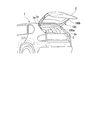
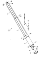
- FIG. 2 is an exploded perspective view of a part of the actuator according to the first embodiment of the present invention.
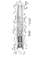
- FIG. 2 is a cross-sectional view along the axial direction of the actuator according to the first embodiment of the present invention.
- It is a side view of the 1st joint part in a 1st embodiment of the present invention.
- It is a side view of a bearing holder in a 1st embodiment of the present invention.
- FIG. 4 is an explanatory diagram showing a state before caulking and fixing a first joint portion to a first housing in the first embodiment of the present invention. It is explanatory drawing which shows the state after swaging and fixing of the 1st joint part to the 1st housing in 1st Embodiment of this invention.
- FIG. 4 is a simplified view showing a state in which an inclined portion is formed in a part of the deformation allowing portion by the jig according to the first embodiment of the present invention. It is a side view of the 1st joint part in a 2nd embodiment of the present invention.
- FIG. 11 is a simplified diagram showing a state in which an inclined portion is formed in a part of a deformation allowing portion by a jig according to a second embodiment of the present invention. It is a side view of the 1st joint part in a 2nd embodiment of the present invention.
- FIG. 1 is a perspective view illustrating an example of an automobile 1 including a vehicle door opening / closing actuator 100 (hereinafter, simply referred to as an actuator 100) according to the first embodiment of the present invention.
- an actuator 100 opens and closes, for example, a tailgate (door) 2 of an automobile 1.
- the tailgate 2 is provided on an upper portion 3a of an opening 3 formed at a rear portion of the vehicle body of the automobile 1 so that the opening 3 can be opened and closed via a hinge mechanism (not shown).
- the actuators 100 are provided on both left and right sides or one side of the opening 3 in the vehicle width direction.
- One end 100a of the actuator 100 is rotatably connected to the outer frame 3s of the opening 3 via a ball stud (not shown).
- the other end 100b of the actuator 100 is rotatably connected to the tailgate 2 via a ball stud not shown.
- the opening 3 side of the actuator 100 may be referred to as one end side or one side
- the tailgate 2 side may be referred to as the other end side or the other side.
- FIG. 2 is an exploded perspective view of a part of the actuator 100.
- FIG. 3 is a cross-sectional view of the actuator 100 along the axial direction.
- the actuator 100 includes a substantially cylindrical first housing (corresponding to a housing in the claims) 6 and the other end 6 b of the first housing 6 (right end in FIGS. 2 and 3).
- a second housing 7 having a substantially cylindrical shape and one end 7a (left end in FIGS. 2 and 3) fitted and fixed to the inner peripheral surface of the second housing 7 and an inner peripheral surface of the other end 7b of the second housing 7
- a rod-shaped body including three housings 6 to 8 of a substantially cylindrical third housing 8 which is fitted as possible.
- each of the housings 6 to 8 will be simply referred to as the axial direction
- the radial direction of each of the housings 6 to 8 will be simply referred to as the radial direction
- the direction along the outer peripheral surface of each of the housings 6 to 8 will be described. Description will be made simply by referring to the circumferential direction.
- the first housing 6 is formed of a metal material such as iron. At one end 6a of the first housing 6, a first joint portion 9 connected to a ball stud (not shown) provided in an outer frame portion 3s (see FIG. 1) of the opening 3 is provided.
- FIG. 4 is a side view of the first joint portion 9.
- the first joint portion 9 includes a substantially disk-shaped plate portion 9 a fitted to the inner peripheral surface of one end 6 a of the first housing 6, and a first housing 6, and a socket portion 9b protruding in one axial direction (outward).
- the plate portion 9a has an insertion hole (not shown) through which a later-described harness cover 26 can be inserted.
- a caulking groove 9c is formed on the outer peripheral surface of the plate portion 9a substantially at the center in the axial direction over the entire circumference. The caulking groove 9c caulks and fixes the first joint portion 9 to the first housing 6.
- a small width groove 9d smaller than the axial width W1 of the caulking groove 9c is formed at both sides of the caulking groove 9c in the axial direction at a predetermined interval K1.
- the narrow groove 9d is also formed over the entire circumference.
- a deformation allowing portion 91 is formed between the small width groove 9d and the caulking groove 9c.
- the deformable portion 91 has lower mechanical strength than the portion other than the deformable portion 91 in the first joint 9. That is, by forming the small-width groove 9d, the mechanical strength of the deformation allowing portion 91 becomes weaker than that of the portion other than the deformation allowing portion 91.
- the dimension of the predetermined interval K1 is set to a dimension in which the mechanical strength of the deformation allowable portion 91 is weaker than the mechanical strength of a portion other than the deformation allowable portion 91.
- the first joint portion 9 is fixed to the first housing 6 by caulking using the deformable portion 91 and the caulking groove 9c.
- the caulking and fixing is performed by forming a plurality of caulking portions 89 on one end 6a side of the first housing 6.
- the plurality of caulking portions 89 are arranged at equal intervals in the circumferential direction. The details of the caulking fixing method will be described later.
- a substantially cylindrical end cover 10 is attached to one end 6a of the first housing 6.
- the end cover 10 is fitted and fixed to the outer peripheral surface of one end 6 a of the first housing 6, and covers a portion where the first joint 9 is fixed to the first housing 6 by caulking.
- the first housing 6 houses a motor unit 11.
- the motor unit 11 includes a substantially cylindrical yoke 12, a magnet 5 fixed to the inner peripheral surface of the yoke 12, an armature 13 rotatably provided inside the yoke 12 in a radial direction, and power supply to the armature 13. And a brush holder unit 16 for performing the operation.
- the yoke 12 is formed of a conductive metal.
- the outer diameter of the yoke 12 is set smaller than the inner diameter of the first housing 6 by a predetermined dimension.
- An armature 13 provided radially inward of the yoke 12 includes a shaft 14 provided so as to be rotatable in the yoke 12, and an armature core 15 made of a magnetic material and fitted and fixed to the outer peripheral surface of the shaft 14. , A coil 20 wound around the armature core 15, and a commutator 17 which is fitted and fixed to the outer peripheral surface of the shaft 14 adjacent to the armature core 15 and to which a terminal portion of the coil 20 is connected.
- the shaft 14 extends axially at the center of the yoke 12 in the radial direction.
- the shaft 14 has one end inserted into the brush holder unit 16 and rotatably supported by the brush holder unit 16.
- the other end of the shaft 14 is connected to a reduction gear unit 27 described later.
- a sensor magnet 21 is attached to one end of the shaft 14.
- the sensor magnet 21 constitutes one of the rotation position detection devices 23 for detecting the rotation position of the shaft 14.
- the brush holder unit 16 for supplying power to the armature 13 includes a resin brush holder 18 caulked and fixed to one end 12a of the yoke 12, and a brush 19 held by the brush holder 18.
- the brush 19 is in sliding contact with the commutator 17.
- the brush 19 is electrically connected to an external power supply (for example, a battery) via a harness (not shown). Thereby, the electric power of the external power supply is supplied to the coil 20 via the brush 19 and the commutator 17.
- a sensor substrate (not shown) is provided on the brush holder 18 so as to radially oppose the outer peripheral surface of the sensor magnet 21 provided on the shaft 14.
- the sensor substrate constitutes the other of the rotation position detection device 23.
- a magnetic detection element (not shown) for detecting a magnetic change on the outer peripheral surface of the sensor magnet 21 is mounted on the sensor substrate. As a result, the rotation position of the shaft 14 can be detected by the rotation position detection device 23.
- a seal part 24 is attached to the first joint part 9 side of the brush holder unit 16.
- the seal portion 24 is formed of a rubber-based material having elasticity.
- the seal part 24 has a seal body 25 formed in a substantially bottomed cylindrical shape so as to cover the brush holder unit 16 from the first joint part 9 side. That is, the seal body 25 extends from the outer periphery of the bottom 25a to the opposite side of the first joint 9 from the outer periphery of the bottom 25a sandwiched by the brush holder 18 and the plate 9a of the first joint 9, and the brush holder unit 16 and a substantially cylindrical peripheral wall portion 25 b interposed between the inner peripheral surface of the first housing 6.
- a harness cover 26 is formed on the bottom 25a of the seal body 25 so as to protrude toward one side (outward) in the axial direction.
- the harness cover 26 is formed in a substantially pipe shape and communicates inside and outside of the seal body 25.
- a harness (not shown) for electrically connecting an external power supply (not shown) and the brush 19 is inserted into the harness cover 26 configured as described above.
- the reduction gear unit 27 connected to the other end of the shaft 14 is configured as a two-stage planetary reduction mechanism having a first-stage planetary gear unit 35 and a second-stage planetary gear unit 36.
- the reduction gear unit 27 reduces the rotation of the shaft 14 in two stages by a first stage planetary gear unit 35 and a second stage planetary gear unit 36 and outputs the reduced rotation.
- the output of the reduction gear unit 27 is transmitted to a screw shaft 38 connected to the second-stage planetary gear unit 36.
- the screw shaft 38 is driven to rotate about the central axis of the shaft 14 in the motor unit 11.
- One end 38a of the screw shaft 38 on the reduction gear portion 27 side is rotatably supported by a bearing holder 39.
- the screw shaft 38 extends so as to project from the bearing holder 39 toward the other side in the axial direction.
- the screw shaft 38 is a so-called trapezoidal screw, and a thread is formed on the outer peripheral surface.
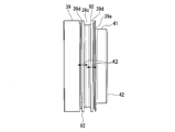
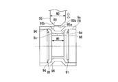
- FIG. 5 is a side view of the bearing holder 39.
- the bearing holder 39 is formed in a substantially cylindrical shape.
- a reduced-diameter portion 41 whose outer diameter is reduced via a step surface 39a is formed on a side opposite to the reduction gear portion 27 with respect to substantially the center in the axial direction.
- An inner flange portion 42 is formed at the tip of the reduced diameter portion 41 (the end opposite to the reduction gear portion 27).
- the bearing 40 is inserted or press-fitted into the inner peripheral surface of the bearing holder 39 between the inner flange portion 42 and the approximate center in the axial direction.
- a bearing holder 39 rotatably supports one end 38a of the screw shaft 38 via the bearing 40.
- On the inner peripheral surface of the bearing holder 39 an enlarged-diameter portion 43 whose inner diameter is enlarged via a step surface 39b is formed on the reduction gear portion 27 side from a position where the bearing 40 is arranged. The other end of the reduction gear portion 27 is inserted into the enlarged diameter portion 43.
- a caulking groove 39c is formed over the entire circumference near the reduced diameter portion 41.
- the caulking groove 39c caulks and fixes the bearing holder 39 to the first housing 6.
- Small width grooves 39d are formed on both sides in the axial direction of the caulking groove 39c with a predetermined interval K2.
- the small width groove 39d is also formed over the entire circumference.
- a deformation allowing portion 92 is formed between the small width groove 39d and the caulking groove 39c.
- the deformable portion 92 has a lower mechanical strength than a portion other than the deformable portion 92 in the bearing holder 39.
- the dimension of the predetermined interval K2 is a dimension in which the mechanical strength of the deformable portion 92 becomes weaker than the mechanical strength of a portion other than the deformable portion 92.
- the bearing holder 39 is fixed to the first housing 6 by caulking using the deformable portion 92 and the caulking groove 39c.
- the caulking and fixing is performed by forming a plurality of caulking portions 88 on the other end 6b side of the first housing 6.
- the plurality of caulking portions 88 are arranged at equal intervals in the circumferential direction. The details of the method of forming the caulking portion 88 (the method of caulking and fixing) will be described later together with the caulking and fixing of the first housing 6 and the first joint portion 9 described above.
- the second housing 7 is provided around the screw shaft 38 rotatably supported by the bearing holder 39 so as to cover the periphery of the screw shaft 38.
- the other end 6 b of the first housing 6 on the side of the reduction gear portion 27 protrudes toward the other side (rightward in FIG. 3) of the bearing holder 39, and is connected to the second housing 7.
- the second housing 7 is formed of a resin material or the like.
- the outer diameter of the second housing 7 is set to be substantially the same as the outer diameter of the first housing 6 except for the one end 7a fitted to the other end 6b of the first housing 6.
- One end 7a side of the second housing 7 is reduced in diameter by a step to form a reduced diameter portion 7c.
- the reduced diameter portion 7c is press-fitted into the other end 6b of the first housing 6 and fixed.
- the first housing 6 and the second housing 7 are integrated with the outer peripheral surface of the first housing 6 and the outer peripheral surface of the second housing 7 being substantially flush with each other.
- the second housing 7 is positioned such that the one end 7a side of the second housing 7 is fitted and fixed to the other end 6b of the first housing 6, and the second housing 7 Is formed so that the other end 7b thereof slightly protrudes.
- the length of the reduced diameter portion 7c of the second housing 7 is such that the reduced diameter portion 7c does not come into contact with the bearing holder 39 when pressed into the other end 6b of the first housing 6.
- an inner flange 46 bent inward in the radial direction is formed at one end 7a of the second housing 7.
- One end of a coil spring 47 described later abuts on the inner flange 46.
- the second housing 7 is provided with a coil spring 47 spirally formed along the inner peripheral surface of the second housing 7.
- One end of the coil spring 47 is in contact with the inner flange 46 of the second housing 7.
- the free length of the coil spring 47 is sufficiently longer than the length of the second housing 7. Therefore, the other end of the coil spring 47 protrudes from the other end 7b of the second housing 7 with one end of the coil spring 47 abutting on the inner flange 46 of the second housing 7.
- the outer diameter of the substantially cylindrical third housing 8 provided at the other end 7 b of the second housing 7 so as to be able to protrude and retract is set slightly smaller than the outer diameter of the second housing 7.
- the other end 7b of the third housing 8 on the motor unit 11 side is inserted into the other end 7b of the second housing 7.
- the other end of the coil spring 47 is housed in the third housing 8.
- the other end 8b of the third housing 8 is formed with an inner flange 53 bent radially inward. The other end of the coil spring 47 abuts on the inner surface of the inner flange 53, and the second joint portion 54 abuts on the outer surface.
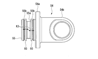
- FIG. 6 is a side view of the second joint portion 54.
- the second joint portion 54 is connected to a ball stud (not shown) provided on the tailgate 2.
- the second joint portion 54 is formed by integrally forming a substantially disk-shaped plate portion 54a in contact with the inner flange 53 of the third housing 8 and a socket portion 54b projecting from the plate portion 54a in the other axial direction (outward). It was done.
- the outer diameter of the plate portion 54a is slightly smaller than the outer diameter of the third housing 8.
- a substantially columnar fixed convex portion 55 protruding into the third housing 8 via the inner flange 53 of the third housing 8 is integrally formed.
- a caulking groove 55a is formed at substantially the center in the axial direction of the fixed projection 55 over the entire circumference.
- the caulking groove 55a caulks and fixes an inner tube (corresponding to a housing in the claims) 56 described later to the fixing protrusion 55.
- ⁇ Narrow width grooves 55b are formed at both sides of the caulking groove 55a in the axial direction with a predetermined interval K3.
- the small width groove 55b is also formed over the entire circumference.
- a deformation allowing portion 93 is formed between the small width groove 55b and the caulking groove 55a.
- the deformable portion 93 has lower mechanical strength than the portion other than the deformable portion 93 in the second joint portion 54. That is, by forming the small width groove 55b, the mechanical strength of the deformation allowing portion 93 becomes weaker than that of the portion other than the deformation allowing portion 93.
- the dimension of the predetermined interval K3 is a dimension in which the mechanical strength of the deformable portion 93 becomes weaker than the mechanical strength of a portion other than the deformable portion 93.
- the other end 56b of the inner tube 56 is caulked and fixed to the fixed convex portion 55 by using the deformation allowing portion 93 and the caulking groove 55a.
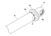
- FIG. 7 is a perspective view showing a state where the inner tube 56 and the second joint portion 54 are fixed.
- the inner tube 56 is formed by, for example, drawing aluminum.
- the outer peripheral surface of the other end 56 b of the inner tube 56 is fitted to the inner peripheral surface of the inner flange 53 of the third housing 8.
- the other end of the coil spring 47 is housed in a space formed between the inner tube 56 and the third housing 8.
- the outer peripheral surface of the fixed convex portion 55 of the second joint portion 54 is fitted to the inner peripheral surface of the other end 56b of the inner tube 56.
- a plurality of caulking portions 87 are formed at positions corresponding to the caulking grooves 55a of the fixed convex portion 55.
- the axial length of the inner tube 56 is slightly longer than the axial length of the third housing 8. For this reason, one end 56 a of the inner tube 56 is inserted into the second housing 7 via one end 8 a of the third housing 8. At one end 56a of the inner tube 56, an inner flange 72 bent radially inward is formed. The screw shaft 38 is inserted radially inward of the inner flange 72. A nut member 58 is fixed to the inner peripheral surface of the inner tube 56 inside (on the other side of) the inner flange 72.
- Nut member 58 is restricted from moving in the axial direction by two retaining rings 73a and 73b.
- the two retaining rings 73a and 73b are disposed on the inner peripheral surface of the inner tube 56 and on both axial sides of the nut member 58. Thereby, the nut member 58 is fixed to the inner tube 56.
- the other end 38b of the screw shaft 38 is screwed to the nut member 58.
- the nut member 58 is fixed to the inner tube 56, and the inner tube 56 is fixed to the second joint portion 54.
- the second joint portion 54 is connected to a ball stud (not shown) provided on the tail gate 2 (see FIG. 1). Therefore, when the screw shaft 38 is rotated, the nut member 58 does not rotate together with the screw shaft 38. When the screw shaft 38 is rotated, the nut member 58 moves along the screw shaft 38.
- a buckling-deformed outer flange portion 38c is formed at the other end 38b of the screw shaft 38.
- a substantially annular stopper 60 is provided so as to be locked to the outer flange portion 38c. The stopper 60 prevents the nut member 58 from coming off from the screw shaft 38.
- the length of the third housing 8 is set to such a length as to slightly compress the coil spring 47 by the inner flange 53 in a state where the nut member 58 is located on the other end 38 b side of the screw shaft 38.
- the coil spring 47 always urges the third housing 8 in the direction in which the third housing 8 projects from the second housing 7.
- the third housing 8 is connected to the screw shaft 38 via an inner tube 56 and a nut member 58. For this reason, the movement of the third housing 8 in the direction protruding from the second housing 7 is restricted. As a result, the coil spring 47 always urges the inner flange 46 of the second housing 7 toward the motor unit 11 side.
- the tailgate 2 (see FIG. 1) provided in the opening 3 of the automobile 1 is closed.
- the tailgate 2 provided in the opening 3 of the automobile 1 is opened. At this time, even if the operation of the motor unit 11 is stopped with the actuator 100 extended, the state in which the third housing 8 projects from the second housing 7 is maintained by the urging force of the coil spring 70.
- FIG. 8A is an explanatory diagram showing a state before the first joint portion 9 is fixed to the first housing 6 by caulking.
- FIG. 8B is an explanatory view showing a state after the first joint portion 9 is fixed to the first housing 6 by caulking. As shown in FIG. 8A, the plate 9 a of the first joint 9 is fitted to the inner peripheral surface of the first housing 6.
- a jig 95 for caulking is pressed from the outside in the radial direction to a position corresponding to the caulking groove 9c of the first housing 6.
- the axial width W2 of the jig 95 is wider than the axial width W1 of the caulking groove 9c.
- chamfered portions 95b are formed at both corners in the axial direction.
- the axial width W2 of the jig 95 is set to be wider than the axial width W1 of the first joint portion 9 (mounting body) of the caulking groove 9c, so that the jig 95 is disposed on both sides of the caulking groove 9c.
- the pressing force of the jig 95 is also applied to the deformed allowable portion 91.
- the deformable portion 91 has a lower mechanical strength than the portion other than the deformable portion 91 in the first joint portion 9, so that the deformable portion 91 is deformed so as to be pushed and spread by the jig 95. For this reason, an inclined portion 96 that is inclined in the axial direction is formed at a position pressed by the jig 95 in the entire circumference of the deformation permitting portion 91.
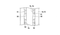
- FIG. 9 is a simplified diagram showing a state in which an inclined portion 96 is formed in a part of the deformation permitting portion 91 in the first joint 9 by the jig 95, and corresponds to a side view of the first joint 9.
- a plurality of inclined portions 96 are formed by the jig 95 not on the entire circumference of the deformable portion 91 but on a part of the deformable portion 91.
- the inclined portions 96 are formed at equal intervals in the circumferential direction.
- the first housing 6 is deformed radially inward so as to be inserted into the inclined portion 96.
- the first housing 6 is deformed radially inward so as to straddle the inclined portions 96 located on both sides of the caulking groove 9c, and the deformed portion is a caulked portion 89 (see FIGS. 2 and 8B). ).
- the caulked portion 89 is formed at a position where each inclined portion 96 communicating with the caulking groove 9c is formed. Therefore, the portion where the inclined portion 96 is not formed hinders the relative rotation between the first housing 6 and the first joint 9. Therefore, relative rotation of the first joint portion 9 with respect to the first housing 6 can be reliably prevented.
- the caulking portion 89 By forming the caulking portion 89, the axial movement of the first joint portion 9 with respect to the first housing 6 can also be reliably prevented.
- small-width grooves 9d are formed around the entire circumference at predetermined intervals K1 on both sides in the axial direction of the caulking grooves 9c formed in the plate portion 9a of the first joint portion 9.
- a deformation allowing portion 91 is formed between the small width groove 9d and the caulking groove 9c.
- the mechanical strength of the deformable portion 91 is made weaker than the mechanical strength of the portion other than the deformable portion 91 in the first joint portion 9.
- Such a deformation allowing portion 91 is deformed by a jig 95 to form an inclined portion 96. Therefore, even when the mechanical strength of the first joint portion 9 itself is increased, the inclined portion 96 can be easily formed with a simple structure. In other words, the relative rotation of the first joint 9 with respect to the first housing 6 and the movement in the axial direction can be reliably prevented without being restricted by the selection of the material of the first joint 9.
- the deformation allowance portions 92 and 93 are also formed in the bearing holder 39 and the fixed convex portion 55 of the second joint portion 54, respectively. For this reason, with respect to the operation and effect such as the above-mentioned caulking and fixing of the first joint portion 9 to the first housing 6, the bearing holder 39 is caulked and fixed to the first housing 6, and the inner tube 56 and the second joint portion 54 are fixed. Can be performed in the same manner.
- the present invention is not limited to these, and the narrow grooves 9d, 39d, and 55b may not be formed over the entire circumference, but may be formed in a plurality along the circumferential direction. That is, a plurality of deformation permitting portions 91 to 93 may be formed side by side in the circumferential direction.
- caulking portions 87 to 89 may be formed at the positions where the deformation allowable portions 91 to 93 are formed. Further, the number of the deformation permitting portions 91 to 93 and the caulking portions 87 to 89 need not be plural. It is sufficient if at least one is formed. Even in such a case, the relative rotation of the first joint portion 9 with respect to the first housing 6, the relative rotation of the bearing holder 39 with respect to the first housing 6, and the relative rotation of the second joint portion 54 with respect to the inner tube 56 are prevented. it can.
- deformation permitting portions 91 to 93 are formed in the first joint portion 9, the bearing holder 39, and the second joint portion 54, respectively, and these deformation permitting portions 91 to 93 are pressed by the jig 95.
- the inclined portion 96 is formed.
- the present invention is not limited to these, and an inclined portion 96 communicating with each of the caulking grooves 9c, 39c, 55a may be formed in advance.
- the inclined portion 96 is not limited to a flat inclined surface, but may be recessed.
- the inclined portion 96 may be curved.
- the caulking portions 87 to 89 may be formed at the portions where the inclined portions 96 are formed. Even in the case of such a configuration, the relative rotation of the first joint 9 with respect to the first housing 6 is not restricted by the material selection of the first joint 9, the bearing holder 39, and the second joint 54. , Relative rotation of the bearing holder 39 with respect to the first housing 6 and relative rotation of the second joint portion 54 with respect to the inner tube 56 can be prevented.
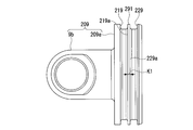
- FIG. 10 is a side view of the first joint 209 in the second embodiment.
- the same reference numerals are given to the same aspects as the first embodiment, and the description is omitted.
- the difference between the first embodiment and the second embodiment is that the first joint portion 9 of the first embodiment has one caulking groove 9c,
- the first joint portion 209 in the form has two caulking grooves 219 and 229 (a first caulking groove 219 and a second caulking groove 229).
- two (two) caulking grooves 219 and 229 are formed over the entire circumference of the plate portion 209a of the first joint portion 209. Have been.
- the two caulking grooves 219, 229 are arranged at a predetermined interval K1 in the axial direction. That is, the deformation allowing portion 291 is formed between the two caulking grooves 219 and 229.
- the deformable portion 291 has lower mechanical strength than the portion other than the deformable portion 291 in the first joint 209.
- FIG. 11 is an explanatory view showing a state where the first joint portion 209 is caulked and fixed to the first housing 6.
- FIG. 11 corresponds to FIG. 8B described above.
- the diameter of the first housing 6 is changed to a position corresponding to each of the caulking grooves 219 and 229.
- a crimping jig 95 (see FIG. 8B, not shown in FIG. 11) is pressed from the outside in the direction.
- the position corresponding to the first swaging groove 219 and the position corresponding to the second swaging groove 229 are alternately pressed in the circumferential direction.
- the first housing 6 is deformed radially inward so as to be inserted into the caulking grooves 219 and 229.
- the deformable portion 291 has a lower mechanical strength than the portion other than the deformable portion 291 in the first joint portion 209, and is deformed so as to be pushed and spread by the jig 95. For this reason, inclined portions 291 a and 291 b (first inclined portion 291 a and second inclined portion 291 b) are formed at locations pressed by the jig 95 in the entire circumference of the deformation allowing portion 291.
- the first inclined portion 291 a of the deformation permitting portion 291 formed by pressing the jig 95 against the first caulking groove 219 is different from the first caulking groove 219 in the side edge 219 a of the first caulking groove 219. From the outside in the axial direction. That is, the first inclined portion 291 a of the deformation allowing portion 291 formed by pressing the jig 95 against the first caulking groove 219 is inclined so as to be inclined toward the second caulking groove 229.
- the second inclined portion 291b of the deformation permitting portion 291 formed by pressing the jig 95 against the second caulking groove 229 moves the second caulking groove 229 from the side edge 229a of the second caulking groove 229 in the axial direction. Is inclined outward. That is, the second inclined portion 291 b of the deformation allowing portion 291 formed by pressing the jig 95 against the second caulking groove 229 is inclined so as to be inclined toward the first caulking groove 219.
- FIG. 12 is a simplified view showing a state in which two inclined portions 291 a and 291 b are formed in a part of the deformation permitting portion 291 in the first joint portion 209 by the jig 95, and a side view of the first joint portion 9. Is equivalent to FIG. 12 corresponds to FIG. 9 described above.
- the position corresponding to the first caulking groove 219 and the position corresponding to the second caulking groove 229 are alternately pressed along the circumferential direction by the jig 95, and as a result,
- the first inclined portions 291a and the second inclined portions 291b are alternately arranged along the circumferential direction.
- the inclination directions of the inclined portions 291a and 291b formed in the deformation permitting portion 291 are alternated along the circumferential direction.
- the relative rotation of the first joint portion 209 with respect to the first housing 6 is more reliably prevented by making the inclination directions of the inclined portions 291a and 291b formed on the deformation permitting portion 291 alternate along the circumferential direction. it can.
- the case where two caulking grooves 219 and 229 are formed over the entire circumference in the plate portion 209a of the first joint portion 209 has been described.
- the case where the deformation allowing portion 291 is formed between the two caulking grooves 219 and 229 has been described.
- the invention is not limited thereto, and the caulking grooves 219 and 229 may not be formed over the entire circumference, but may be formed along the circumferential direction. That is, the deformation permitting portion 291 may be formed intermittently in the circumferential direction.
- the present invention is not limited to these, and the inclined portions 291a and 291b communicating with the caulking grooves 219 and 229 may be formed in advance.
- the inclined portions 291a and 291b are not limited to flat inclined surfaces, but may be recessed.
- the inclined portions 291a and 291b may be curved.
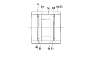
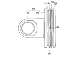
- FIG. 13 is a side view of the first joint 309 in the second embodiment.
- FIG. 13 corresponds to FIG. 10 described above.
- the same reference numerals are given to the same aspects as the first embodiment and the second embodiment, and the description is omitted.
- the difference between the second embodiment and the third embodiment is that in the second embodiment, one deformation allowance portion 291 is formed between two caulking grooves 219 and 229.
- a small width groove 9d is formed over the entire circumference between the two caulking grooves 219 and 229.
- the narrow groove 9d and each of the caulking grooves 219 and 229 are formed with a predetermined interval K1.
- the dimension of the predetermined interval K1 is set to a dimension in which the mechanical strength of the deformation allowable portion 91 is weaker than the mechanical strength of a portion other than the deformation allowable portion 91. Since the small width groove 9d is formed, the deformation allowing portion 291 is formed between the small width groove 9d and each of the caulking grooves 219 and 229. That is, the deformation permitting portion 291 is formed in two lines.
- the deformable portion 291 has a lower mechanical strength than the portion other than the deformable portion 291 in the first joint portion 309, and is deformed so as to be pushed and spread by the jig 95. Therefore, according to the above-described third embodiment, the same effects as those of the above-described second embodiment can be obtained.
- the case where the two caulking grooves 219 and 229 are formed over the entire circumference in the plate portion 309a of the first joint portion 309 has been described.
- the case where the small width groove 9d is formed over the entire circumference between the two caulking grooves 219 and 229 has been described.
- the case where the deformation permitting portion 291 is formed between the narrow groove 9d and each of the caulking grooves 219 and 229 has been described.
- the invention is not limited thereto, and the caulking grooves 219 and 229 and the narrow groove 9d may not be formed over the entire circumference, but may be formed in a plurality in the circumferential direction. That is, the two deformable portions 291 may be formed intermittently in the circumferential direction.
- the inclined portions 291a and 291b communicating with the respective caulking grooves 219 and 229 may be formed in advance.
- the jig 95 is alternately pressed from the outside in the radial direction to the position corresponding to each of the swaging grooves 219 and 229 of the first housing 6.
- the present invention is not limited to this, and the same position may be pressed by the jig 95 in the circumferential direction of each of the caulking grooves 219 and 229. Since the small width groove 9 d is interposed between the two deformable portions 291, the jig 95 can press the same position in the circumferential direction of each of the caulking grooves 219 and 229.
- first joint portions 209 and 309 have been described.
- the present invention is not limited to this, and the configurations of the plate portions 209a and 309a of the first joint portions 209 and 309 may be applied to the bearing holder 39 and the second joint portion 54.
- the present invention is not limited to the above embodiment, and includes various modifications of the above embodiment without departing from the spirit of the present invention.
- the actuator 100 is the vehicle door opening / closing actuator 100 that opens / closes the tailgate 2 of the automobile 1 .
- the present invention is not limited to this, and the actuator 100 can be employed in various devices.
- the present invention is not limited to this, and the screw shaft 38 may be directly connected to the shaft 14.
- the screw shaft 38 may be rotatably supported by the bearing 40 provided on the bearing holder 39, or the shaft 14 may be rotatably supported.
- the reduction gear unit 27 is not limited to the two-stage planetary reduction mechanism, and various reduction mechanisms can be adopted.
- the actuator 100 includes one end 7a (FIG. 2, FIG. 2) on the inner peripheral surface of the first housing 6 having a substantially cylindrical shape and the other end 6b (the right end in FIGS. 2 and 3) of the first housing 6.
- the present invention is not limited to this, and the first housing 6 and the second housing 7 may be integrated into one housing.
- the caulking portion of the housing is formed at the location where the caulking groove is formed, so that the axial movement of the mounting body with respect to the housing can be reliably prevented.
- the inclined portion is formed only at a part of the side edge of the caulking groove, and is not formed over the entire circumference. For this reason, by forming the swaged portion of the housing at the position where the inclined portion is formed, the relative rotation with respect to the housing can be reliably prevented.
- the caulking portion is formed on the inclined portion, there is no need to deform the mounting body itself. For this reason, the mechanical strength of the mounting body can be increased, and there is no restriction on the material selection.
- second stage planetary gear part (reduction gear) Mechanism) 38: screw shaft (drive shaft), 39: bearing holder (attachment), 54: second joint part (attachment), 55: fixed projection, 58: nut member (follower), 87, 88 , 89: caulking part, 91, 92, 93, 291: deformation permitting part, 96: inclined part, 100: vehicle door opening / closing actuator (actuator), 291a: first inclined part (inclined part), 291b: second inclined part Part (inclined part)
Landscapes
- Engineering & Computer Science (AREA)
- General Engineering & Computer Science (AREA)
- Mechanical Engineering (AREA)
- Power Engineering (AREA)
- Power-Operated Mechanisms For Wings (AREA)
- Mutual Connection Of Rods And Tubes (AREA)
Abstract
第1ジョイント部(9)は、外周面に全周に渡って形成されたかしめ溝(9c)と、かしめ溝(9c)の側縁の一部に少なくとも1つ形成され、かしめ溝(9c)の側縁から軸方向の外側へ傾斜された傾斜部(96)と、を有し、第1ハウジング(6)は、かしめ溝(9c)に対応する箇所のうち、少なくとも傾斜部(96)が形成されている箇所に、かしめ部(89)が形成されている。
Description
本発明は、固定構造、アクチュエータ、車両ドア開閉用アクチュエータ、及び固定方法に関する。
本願は、2018年8月8日に、日本に出願された特願2018-149557号に基づき優先権を主張し、その内容をここに援用する。
本願は、2018年8月8日に、日本に出願された特願2018-149557号に基づき優先権を主張し、その内容をここに援用する。
従来から、車両ドア開閉装置として、アクチュエータを設ける構成が知られている。アクチュエータは、車体側の開口部の周囲と、この開口部に開閉可能に設けられたテールゲートとの間に、軸方向に伸縮駆動することによってテールゲートを開閉動作させる(例えば、特許文献1参照)。
特許文献1のアクチュエータは、筒状の第1ハウジングと、第1ハウジングの一端側の内周面に嵌合され、第1ハウジングに出没可能に設けられた第2ハウジングと、を備えている。また、アクチュエータは、第1ハウジングの他端側内に設けられたモータと、モータの回転力を受けて回転駆動する駆動軸(スクリュー軸)と、を備えている。駆動軸は、第1ハウジング及び第2ハウジング内に、軸方向に沿って配置されている。
また、駆動軸は、モータ側の端部が軸受を介して回転自在に支持されている。軸受は、第1ハウジングにおける一端側の内周面に嵌合された軸受ホルダに支持されている。駆動軸には、従動部(ナット部材)が螺合されている。従動部は、第2ハウジングの径方向内側に設けられたインナーチューブに固定されており、駆動軸に対して相対回転不能である。
第1ハウジングの他端、及びインナーチューブの第1ハウジングとは反対側端には、それぞれの内周面にジョイント部が嵌合されている。これらジョイント部のうち、一方が車体側の開口部の周囲に取り付けられる。他方のジョイント部は、テールゲートに取り付けられる。
このような構成のもと、駆動軸が回転すると、従動部が駆動軸の軸方向に沿ってスライド移動する。すると、従動部が固定されているインナーチューブ、及びインナーチューブと一体化されている第2ハウジングが、第1ハウジングに対して出没移動する。これにより、テールゲートが開閉動作される。
このような構成のもと、駆動軸が回転すると、従動部が駆動軸の軸方向に沿ってスライド移動する。すると、従動部が固定されているインナーチューブ、及びインナーチューブと一体化されている第2ハウジングが、第1ハウジングに対して出没移動する。これにより、テールゲートが開閉動作される。
ここで、第1ハウジングにおける一端側の内周面に嵌合された軸受ホルダ、及び第1ハウジングにおける他端の内周面に嵌合されたジョイント部は、それぞれ第1ハウジングをかしめることにより、第1ハウジングに固定されている。インナーチューブにおける反対側端の内周面に嵌合されたジョイント部は、インナーチューブをかしめることにより固定されている。
各ジョイント部や軸受ホルダには、軸方向の荷重に加え、回転トルクもかかる。このため、回転トルクによって、第1ハウジングやインナーチューブに対してジョイント部や軸受ホルダが相対回転してしまうことを防止する必要がある。すなわち、第1ハウジングやインナーチューブをかしめて変形させる場合、周方向の複数個所においてジョイント部や軸受ハウジングの外周面も同時に変形させている。このように構成することで、ジョイント部や軸受ハウジングの外周面に、かしめ変形された箇所とかしめ変形されていない箇所とが周方向に並んで形成される。このため、第1ハウジングやインナーチューブに対し、ジョイント部や軸受ホルダが相対回転してしまうことを防止できる。
しかしながら、第1ハウジングやインナーチューブのかしめと同時にジョイント部や軸受ホルダを変形させる場合、第1ハウジングやインナーチューブの機械的強度に対し、ジョイント部や軸受ホルダの機械的強度を弱くする必要がある。このため、第1ハウジング、インナーチューブ、ジョイント部、及び軸受ホルダの材料選定に制限がかかってしまう可能性があった。
テールゲートの重量等を考慮すると、ジョイント部や軸受ホルダの機械的強度を高める必要もある。このため、ジョイント部や軸受ホルダの材料選定がさらに困難になる可能性があった。
テールゲートの重量等を考慮すると、ジョイント部や軸受ホルダの機械的強度を高める必要もある。このため、ジョイント部や軸受ホルダの材料選定がさらに困難になる可能性があった。
そこで、本発明は、筒状のハウジングに嵌合されるジョイント部や軸受ホルダ等の取付体の機械的強度を高めつつ、ハウジングを容易にかしめてハウジングと取付体との相対回転も確実に防止できる固定構造、アクチュエータ、車両ドア開閉用アクチュエータ、及び固定方法を提供する。
上記の課題を解決するために、本発明に係る固定構造は、筒状のハウジングと、前記ハウジングの内周面に嵌合された取付体と、を備え、前記ハウジングにかしめ部を形成して前記ハウジングと前記取付体とを固定する固定構造において、前記取付体は、外周面に全周に渡って形成された少なくとも1つのかしめ溝と、各前記かしめ溝の側縁の一部に少なくとも1つ形成され、対応する前記かしめ溝の側縁から前記ハウジングの軸方向の外側へ傾斜された傾斜部と、を有し、前記ハウジングは、前記かしめ溝に対応する箇所のうち、少なくとも前記傾斜部が形成されている箇所に、かしめ部が形成されている。
まず、かしめ溝が形成されている箇所にハウジングのかしめ部を形成することにより、ハウジングに対する取付体の軸方向の移動を確実に防止できる。また、傾斜部は、かしめ溝の側縁の一部に形成されているだけであり、全周に渡って形成されていない。このため、傾斜部が形成されている箇所にハウジングのかしめ部を形成することにより、ハウジングに対する相対回転も確実に防止できる。しかも、傾斜部にかしめ部を形成するので、取付体そのものを変形させる必要がない。このため、取付体の機械的強度を高めることが可能になり、材料選定にも制限を受けることがない。
本発明に係る固定構造において、少なくとも前記傾斜部は、前記取付体の前記傾斜部以外の箇所の機械的強度よりも機械的強度が弱い変形許容部であってもよい。
このように構成することで、例えば取付板の機械的強度を高めた場合であっても、ハウジングのかしめ部を容易に形成することができる。このため、取付体の機械的強度を高めつつ、ハウジングを容易にかしめてハウジングと取付体との相対回転も確実に防止できる。
本発明に係る固定構造において、前記かしめ溝を1つ有し、前記取付体は、前記かしめ溝と前記ハウジングの軸方向で隣り合うように形成され、前記かしめ溝における前記ハウジングの前記軸方向の幅よりも小さい小幅溝を有し、前記かしめ溝と前記小幅溝との間が、前記変形許容部であってもよい。
かしめ溝の隣に小幅溝を形成することにより、これらかしめ溝と小幅溝との間の機械的強度が弱くなる。このため、かしめ溝と小幅溝との間が容易に変形可能な変形許容部となる。このように、簡素な構造で、取付体に容易に変形許容部を設けることができる。
本発明に係る固定構造は、前記小幅溝を前記取付体の全周に渡って形成してもよい。
小幅溝が周方向の一部にのみ形成されていると、小幅溝が形成されている箇所に合わせてハウジングにかしめ部を形成する必要がある。このため、取付体とかしめ部を形成するための治具との位置決めが必要になる。しかしながら、小幅溝を取付体の全周に渡って形成することにより、取付体と治具との位置決めが不要になる。よって、かしめ部を形成するための製造工程が簡素化できる。
本発明に係る固定構造において、前記かしめ溝を2つ有し、前記取付体は、2つの前記かしめ溝の間に設けられた前記変形許容部を有し、前記傾斜部を少なくとも2つ有し、各前記傾斜部の傾斜方向は、周方向に沿って交互となってもよい。
このように構成することで、ハウジングを容易にかしめてハウジングと取付体との相対回転をより確実に防止できる。
本発明に係る固定構造において、前記かしめ溝を2つ有し、前記取付体は、2つの前記かしめ溝の間に設けられ、前記かしめ溝における前記ハウジングの前記軸方向の幅よりも小さい小幅溝を有し、各前記かしめ溝と前記小幅溝との間が、前記変形許容部でもよい。
このように構成することで、ハウジングを容易にかしめてハウジングと取付体との相対回転をより確実に防止できる。また、固定構造のバリエーションを増やすことができる。
本発明に係るアクチュエータは、上記に記載の固定構造を有するアクチュエータであって、前記取付体は、前記ハウジングの一端に設けられ被取付部に取り付けられるジョイント部である。
このように構成することで、ハウジングを容易にかしめてハウジングとジョイント部との相対回転も確実に防止できる。
本発明に係るアクチュエータは、前記ハウジング内に回転自在に設けられたアーマチュアと、前記ハウジング内に設けられ前記アーマチュアの回転を減速して出力する減速機構と、前記減速機構に連結され、前記ハウジングの軸方向に延びる駆動軸と、前記駆動軸に螺合され、前記駆動軸に回転に伴って前記駆動軸上をスライド移動する従動部と、2つの前記取付体と、を備え、前記取付体は、前記ジョイント部、及び前記ハウジングの前記一端とは反対側の他端に設けられ、前記駆動軸を回転自在に支持する軸受ホルダであってもよい。
このように構成することで、ハウジングを容易にかしめてハウジングとジョイント部、及びハウジングと軸受ホルダとの相対回転も確実に防止可能なアクチュエータを提供できる。
本発明に係る車両ドア開閉用アクチュエータは、上記に記載のアクチュエータを、開口部に対して開閉可能に設けられたドアを開閉駆動するために用いてもよい。
このように構成することで、筒状のハウジングに嵌合されるジョイント部や軸受ホルダ等の取付体の機械的強度を高めつつ、ハウジングを容易にかしめてハウジングと取付体との相対回転も確実に防止できる。
本発明に係る固定方法は、筒状のハウジングと、前記ハウジングの内周面に嵌合された取付体と、を固定するための固定方法において、前記取付体の外周面に全周に渡って少なくとも1つのかしめ溝を形成するとともに、各前記かしめ溝の側縁の少なくとも一部に、該一部以外の箇所の機械的強度よりも機械的強度の弱い変形許容部を形成し、前記ハウジングの前記変形許容部に対応する位置、及び前記変形許容部に対応する位置のかしめ溝を、前記ハウジングの外周面側から押圧してかしめ部を形成するとともに、前記変形許容部に、対応する前記かしめ溝に対して前記取付体の軸方向の外側へ傾斜された傾斜部を形成する。
このような方法とすることで、筒状のハウジングに嵌合されるジョイント部や軸受ホルダ等の取付体の機械的強度を高めつつ、ハウジングを容易にかしめてハウジングと取付体との相対回転も確実に防止できる。
本発明に係る固定方法は、前記かしめ溝を1つ形成するとともに、前記かしめ溝に隣接するように小幅溝を少なくとも一部に形成し、前記かしめ溝と前記小幅溝との間を、前記変形許容部としてもよい。
このような方法とすることで、簡素な構造で取付体に容易に変形許容部を設けることができる。
本発明に係る固定方法は、前記かしめ溝の軸方向両側に、前記小幅溝を前記取付体の全周に渡って形成してもよい。
このような方法によって小幅溝を取付体の全周に渡って形成すると、取付体と治具との位置決めが不要になる。このため、かしめ部を形成するための製造工程が簡素化できる。
本発明に係る固定方法は、前記かしめ溝を2つ形成するとともに、2つの前記かしめ溝の間を変形許容部とし、各前記傾斜部の傾斜方向を周方向に沿って交互としてもよい。
このような方法とすることで、ハウジングを容易にかしめてハウジングと取付体との相対回転をより確実に防止できる。
本発明によれば、かしめ溝が形成されている箇所にハウジングのかしめ部を形成することにより、ハウジングに対する取付体の軸方向の移動を確実に防止できる。また、傾斜部は、かしめ溝の側縁の一部に形成されているだけであり、全周に渡って形成されていない。このため、傾斜部が形成されている箇所にハウジングのかしめ部を形成することにより、ハウジングに対する相対回転も確実に防止できる。しかも、傾斜部にかしめ部を形成するので、取付体そのものを変形させる必要がない。このため、取付体の機械的強度を高めることが可能になり、材料選定にも制限を受けることがない。
次に、本発明の実施形態を図面に基づいて説明する。
(第1実施形態)
(車両ドア開閉用アクチュエータ)
図1は、本発明の第1実施形態における車両ドア開閉用アクチュエータ100(以下、単にアクチュエータ100という)を備えた自動車1の例を示す斜視図である。
図1に示すように、アクチュエータ100は、自動車1の例えばテールゲート(ドア)2を開閉する。テールゲート2は、自動車1の車体後部に形成された開口部3の上部3aに、不図示のヒンジ機構を介して開口部3を開閉可能に設けられている。
(車両ドア開閉用アクチュエータ)
図1は、本発明の第1実施形態における車両ドア開閉用アクチュエータ100(以下、単にアクチュエータ100という)を備えた自動車1の例を示す斜視図である。
図1に示すように、アクチュエータ100は、自動車1の例えばテールゲート(ドア)2を開閉する。テールゲート2は、自動車1の車体後部に形成された開口部3の上部3aに、不図示のヒンジ機構を介して開口部3を開閉可能に設けられている。
アクチュエータ100は、開口部3の車幅方向左右両側又は片側にそれぞれ設けられている。そして、開口部3の外枠部3sに、不図示のボールスタッドを介してアクチュエータ100の一端100aが回動可能に連結されている。テールゲート2に、不図示のボールスタッドを介してアクチュエータ100の他端100bが回動可能に連結されている。
以下では、アクチュエータ100の開口部3側を、一端側または一方と称し、テールゲート2側を、他端側、又は他方と称して説明する場合がある。
以下では、アクチュエータ100の開口部3側を、一端側または一方と称し、テールゲート2側を、他端側、又は他方と称して説明する場合がある。
図2は、アクチュエータ100の一部を分解した斜視図である。図3は、アクチュエータ100の軸方向に沿う断面図である。
図2、図3に示すように、アクチュエータ100は、略円筒状の第1ハウジング(請求項におけるハウジングに相当)6と、第1ハウジング6の他端6b(図2、図3における右側端)の内周面に、一端7a(図2、図3における左側端)が嵌合固定されている略円筒状の第2ハウジング7と、第2ハウジング7の他端7bの内周面に、出没可能に嵌合されている略円筒状の第3ハウジング8と、の3つのハウジング6~8を備えた棒状体である。
以下の説明では、各ハウジング6~8の中心軸に沿う方向を単に軸方向と称し、各ハウジング6~8の径方向を単に径方向と称し、各ハウジング6~8の外周面に沿う方向を単に周方向と称して説明する。
図2、図3に示すように、アクチュエータ100は、略円筒状の第1ハウジング(請求項におけるハウジングに相当)6と、第1ハウジング6の他端6b(図2、図3における右側端)の内周面に、一端7a(図2、図3における左側端)が嵌合固定されている略円筒状の第2ハウジング7と、第2ハウジング7の他端7bの内周面に、出没可能に嵌合されている略円筒状の第3ハウジング8と、の3つのハウジング6~8を備えた棒状体である。
以下の説明では、各ハウジング6~8の中心軸に沿う方向を単に軸方向と称し、各ハウジング6~8の径方向を単に径方向と称し、各ハウジング6~8の外周面に沿う方向を単に周方向と称して説明する。
第1ハウジング6は、例えば鉄等の金属製材料により形成されている。この第1ハウジング6の一端6aに、開口部3の外枠部3s(図1参照)に設けられたボールスタッド(不図示)に連結される第1ジョイント部9が設けられている。
(第1ジョイント部)
図4は、第1ジョイント部9の側面図である。
図3、図4に示すように、第1ジョイント部9は、第1ハウジング6における一端6aの内周面に嵌合された略円板状のプレート部9aと、プレート部9aから第1ハウジング6の軸方向一方(外方)に突出するソケット部9bと、が一体成形されている。
プレート部9aには、後述するハーネスカバー26を挿通可能な不図示の挿通孔が形成されている。プレート部9aの外周面には、軸方向略中央に、かしめ溝9cが全周に渡って形成されている。かしめ溝9cは、第1ハウジング6に第1ジョイント部9をかしめ固定する。
図4は、第1ジョイント部9の側面図である。
図3、図4に示すように、第1ジョイント部9は、第1ハウジング6における一端6aの内周面に嵌合された略円板状のプレート部9aと、プレート部9aから第1ハウジング6の軸方向一方(外方)に突出するソケット部9bと、が一体成形されている。
プレート部9aには、後述するハーネスカバー26を挿通可能な不図示の挿通孔が形成されている。プレート部9aの外周面には、軸方向略中央に、かしめ溝9cが全周に渡って形成されている。かしめ溝9cは、第1ハウジング6に第1ジョイント部9をかしめ固定する。
かしめ溝9cの軸方向両側には、所定間隔K1をあけてかしめ溝9cの軸方向の幅W1よりも小さい小幅溝9dが形成されている。小幅溝9dも全周に渡って形成されている。小幅溝9dを形成することにより、この小幅溝9dとかしめ溝9cとの間に、変形許容部91が形成される。変形許容部91は、第1ジョイント部9における変形許容部91以外の箇所よりも機械的強度が弱い。つまり、小幅溝9dを形成することによって、変形許容部91の機械的強度が、この変形許容部91以外の箇所よりも弱くなる。所定間隔K1の寸法は、変形許容部91の機械的強度が、この変形許容部91以外の箇所の機械的強度よりも弱くなる寸法に設定される。
このような変形許容部91とかしめ溝9cとを利用して、第1ハウジング6への第1ジョイント部9のかしめ固定が行われる。かしめ固定は、第1ハウジング6の一端6a側に複数のかしめ部89を形成することにより行われる。複数のかしめ部89は、周方向に等間隔で配置されている。かしめ固定の方法についての詳細は後述する。
また、第1ハウジング6の一端6aには、略円筒状のエンドカバー10が装着されている。エンドカバー10は、第1ハウジング6の一端6aの外周面に嵌合固定されており、第1ハウジング6に第1ジョイント部9がかしめ固定された箇所をカバーしている。
また、第1ハウジング6の一端6aには、略円筒状のエンドカバー10が装着されている。エンドカバー10は、第1ハウジング6の一端6aの外周面に嵌合固定されており、第1ハウジング6に第1ジョイント部9がかしめ固定された箇所をカバーしている。
(モータ部)
第1ハウジング6には、モータ部11が収納されている。
モータ部11は、略円筒状のヨーク12と、ヨーク12の内周面に固定されているマグネット5と、ヨーク12の径方向内側に回転自在に設けられたアーマチュア13と、アーマチュア13に給電を行うブラシホルダユニット16と、を備えている。ヨーク12は、導電性を有する金属により形成されている。ヨーク12の外径は、第1ハウジング6の内径よりも所定寸法小さく設定されている。
第1ハウジング6には、モータ部11が収納されている。
モータ部11は、略円筒状のヨーク12と、ヨーク12の内周面に固定されているマグネット5と、ヨーク12の径方向内側に回転自在に設けられたアーマチュア13と、アーマチュア13に給電を行うブラシホルダユニット16と、を備えている。ヨーク12は、導電性を有する金属により形成されている。ヨーク12の外径は、第1ハウジング6の内径よりも所定寸法小さく設定されている。
ヨーク12の径方向内側に設けられたアーマチュア13は、ヨーク12内で回転可能となるように設けられたシャフト14と、シャフト14の外周面に嵌合固定され、磁性材からなるアーマチュアコア15と、アーマチュアコア15に巻回されているコイル20と、シャフト14の外周面にアーマチュアコア15と隣接して嵌合固定され、コイル20の端末部が接続されるコンミテータ17と、を備えている。
シャフト14は、ヨーク12の径方向中心で軸方向に沿って延びている。そして、シャフト14は、一端がブラシホルダユニット16に挿通されてこのブラシホルダユニット16に回転自在に支持されている。シャフト14は、他端が後述の減速ギヤ部27に連結されている。シャフト14の一端には、センサマグネット21が取り付けられている。センサマグネット21は、シャフト14の回転位置を検出するための回転位置検出装置23の一方を構成している。
アーマチュア13に給電を行うブラシホルダユニット16は、ヨーク12の一端12aにかしめ固定されている樹脂製のブラシホルダ18と、ブラシホルダ18に保持されているブラシ19と、を備えている。このブラシ19が、コンミテータ17に摺接されている。ブラシ19は、不図示のハーネスを介して外部電源(例えば、バッテリ)と電気的に接続されている。これにより、外部電源の電力が、ブラシ19、コンミテータ17を介してコイル20に供給される。
ブラシホルダ18には、シャフト14に設けられたセンサマグネット21の外周面と径方向で対向するように、不図示のセンサ基板が設けられている。センサ基板は、回転位置検出装置23の他方を構成している。センサ基板には、センサマグネット21の外周面の磁気変化を検出する不図示の磁気検出素子が実装されている。この結果、回転位置検出装置23によって、シャフト14の回転位置を検出できる。
ブラシホルダユニット16の第1ジョイント部9側には、シール部24が装着されている。シール部24は、弾性を有したゴム系材料により形成されている。シール部24は、ブラシホルダユニット16を第1ジョイント部9側から覆うように略有底筒状に形成されたシール本体25を有している。すなわち、シール本体25は、ブラシホルダ18と第1ジョイント部9のプレート部9aとにより挟持された底部25aと、底部25aの外周縁から第1ジョイント部9とは反対側に延び、ブラシホルダユニット16と第1ハウジング6の内周面との間に介在される略円筒状の周壁部25bと、により構成されている。
シール本体25の底部25aには、ハーネスカバー26が軸方向一方(外方)に向かって突出形成されている。ハーネスカバー26は、略パイプ状に形成されており、シール本体25の内外を連通している。このように構成されたハーネスカバー26内に、不図示の外部電源とブラシ19とを電気的に接続するための不図示のハーネスが挿通される。
このような構成のもと、外部電源の電力が、不図示のハーネス、ブラシ19、及びコンミテータ17を介してコイル20に供給されると、アーマチュアコア15に磁界が形成される。そして、この磁界とヨーク12に固定されたマグネットとの間に生じる磁気的な吸引力や反発力によって、シャフト14がその中心軸回りに回転駆動する。また、シャフト14と一体となってセンサマグネット21が回転する。このセンサマグネット21が回転した際の磁気変化を回転位置検出装置23によって検出し、シャフト14の回転位置が検出される。
(減速ギヤ部)
シャフト14の他端に連結されている減速ギヤ部27は、第1段遊星ギヤ部35と、第2段遊星ギヤ部36と、を有する2段遊星減速機構として構成されている。減速ギヤ部27は、シャフト14の回転を、第1段遊星ギヤ部35と第2段遊星ギヤ部36とにより2段で減速して出力する。減速ギヤ部27の出力は、第2段遊星ギヤ部36に連結されているスクリュー軸38に伝達される。
シャフト14の他端に連結されている減速ギヤ部27は、第1段遊星ギヤ部35と、第2段遊星ギヤ部36と、を有する2段遊星減速機構として構成されている。減速ギヤ部27は、シャフト14の回転を、第1段遊星ギヤ部35と第2段遊星ギヤ部36とにより2段で減速して出力する。減速ギヤ部27の出力は、第2段遊星ギヤ部36に連結されているスクリュー軸38に伝達される。
スクリュー軸38は、モータ部11におけるシャフト14の中心軸回りに回転駆動する。スクリュー軸38の減速ギヤ部27側の一端38aは、軸受ホルダ39に回転自在に支持されている。スクリュー軸38は、軸受ホルダ39から軸方向他方に向かって突出するように延出されている。スクリュー軸38は、いわゆる台形ネジであって、外周面にネジ条が形成されている。
(軸受ホルダ)
図5は、軸受ホルダ39の側面図である。
図3、図5に示すように、軸受ホルダ39は、略円筒状に形成されている。軸受ホルダ39の外周面には、軸方向略中央よりも減速ギヤ部27とは反対側に、段差面39aを介して外径が縮径された縮径部41が形成されている。縮径部41の先端(減速ギヤ部27とは反対側端)には、内フランジ部42が形成されている。
図5は、軸受ホルダ39の側面図である。
図3、図5に示すように、軸受ホルダ39は、略円筒状に形成されている。軸受ホルダ39の外周面には、軸方向略中央よりも減速ギヤ部27とは反対側に、段差面39aを介して外径が縮径された縮径部41が形成されている。縮径部41の先端(減速ギヤ部27とは反対側端)には、内フランジ部42が形成されている。
軸受ホルダ39の内周面には、内フランジ部42から軸方向略中央に至る間に、軸受40が挿入、又は圧入されている。この軸受40を介し、軸受ホルダ39がスクリュー軸38の一端38aを回転自在に支持している。
軸受ホルダ39の内周面には、軸受40が配置される箇所よりも減速ギヤ部27側に、段差面39bを介して内径が拡径された拡径部43が形成されている。この拡径部43に、減速ギヤ部27の他端側が挿入されている。
軸受ホルダ39の内周面には、軸受40が配置される箇所よりも減速ギヤ部27側に、段差面39bを介して内径が拡径された拡径部43が形成されている。この拡径部43に、減速ギヤ部27の他端側が挿入されている。
軸受ホルダ39の外周面には、縮径部41寄りにかしめ溝39cが全周に渡って形成されている。かしめ溝39cは、第1ハウジング6に軸受ホルダ39をかしめ固定する。
かしめ溝39cの軸方向両側には、所定間隔K2をあけて小幅溝39dが形成されている。小幅溝39dも全周に渡って形成されている。小幅溝39dを形成することにより、この小幅溝39dとかしめ溝39cとの間に、変形許容部92が形成される。変形許容部92は、軸受ホルダ39における変形許容部92以外の箇所よりも機械的強度が弱い。つまり、小幅溝39dを形成することによって、変形許容部92の機械的強度が、この変形許容部92以外の箇所よりも弱くなる。所定間隔K2の寸法は、変形許容部92の機械的強度が、この変形許容部92以外の箇所の機械的強度よりも弱くなる寸法である。
かしめ溝39cの軸方向両側には、所定間隔K2をあけて小幅溝39dが形成されている。小幅溝39dも全周に渡って形成されている。小幅溝39dを形成することにより、この小幅溝39dとかしめ溝39cとの間に、変形許容部92が形成される。変形許容部92は、軸受ホルダ39における変形許容部92以外の箇所よりも機械的強度が弱い。つまり、小幅溝39dを形成することによって、変形許容部92の機械的強度が、この変形許容部92以外の箇所よりも弱くなる。所定間隔K2の寸法は、変形許容部92の機械的強度が、この変形許容部92以外の箇所の機械的強度よりも弱くなる寸法である。
このような変形許容部92とかしめ溝39cとを利用して、第1ハウジング6への軸受ホルダ39のかしめ固定が行われる。かしめ固定は、第1ハウジング6の他端6b側に複数のかしめ部88を形成することにより行われる。複数のかしめ部88は、周方向に等間隔で配置されている。このかしめ部88の形成方法(かしめ固定の方法)についての詳細も、前述の第1ハウジング6と第1ジョイント部9とのかしめ固定と併せて後述する。
軸受ホルダ39に回転自在に支持されているスクリュー軸38の周囲には、このスクリュー軸38の周囲を覆うように、第2ハウジング7が設けられている。
第1ハウジング6の減速ギヤ部27側の他端6bは、軸受ホルダ39よりも他方(図3における右方)に向かって突出しており、第2ハウジング7と結合されている。
第1ハウジング6の減速ギヤ部27側の他端6bは、軸受ホルダ39よりも他方(図3における右方)に向かって突出しており、第2ハウジング7と結合されている。
(第2ハウジング)
図2、図3に示すように、第2ハウジング7は、樹脂材料等により形成されている。第2ハウジング7の外径は、第1ハウジング6の他端6bに嵌合されている一端7a側を除いて、第1ハウジング6の外径とほぼ同一に設定されている。第2ハウジング7の一端7a側は、段差により縮径形成されて縮径部7cとされている。この縮径部7cが、第1ハウジング6の他端6bに圧入されて固定されている。これにより、第1ハウジング6の外周面と第2ハウジング7の外周面とがほぼ面一の状態で、第1ハウジング6と第2ハウジング7とが一体化される。
図2、図3に示すように、第2ハウジング7は、樹脂材料等により形成されている。第2ハウジング7の外径は、第1ハウジング6の他端6bに嵌合されている一端7a側を除いて、第1ハウジング6の外径とほぼ同一に設定されている。第2ハウジング7の一端7a側は、段差により縮径形成されて縮径部7cとされている。この縮径部7cが、第1ハウジング6の他端6bに圧入されて固定されている。これにより、第1ハウジング6の外周面と第2ハウジング7の外周面とがほぼ面一の状態で、第1ハウジング6と第2ハウジング7とが一体化される。
第2ハウジング7は、この第2ハウジング7の一端7a側を第1ハウジング6の他端6bに嵌合固定させた状態で、スクリュー軸38の他端(先端部)38bよりも第2ハウジング7の他端7bが若干突出するように形成されている。第2ハウジング7の縮径部7cの長さは、第1ハウジング6の他端6bに圧入した際、軸受ホルダ39に縮径部7cが当接されない長さである。
第2ハウジング7の一端7aには、径方向内側に曲折させてなる内フランジ46が形成されている。この内フランジ46には、後述するコイルスプリング47の一端が当接される。
第2ハウジング7の一端7aには、径方向内側に曲折させてなる内フランジ46が形成されている。この内フランジ46には、後述するコイルスプリング47の一端が当接される。
第2ハウジング7には、この第2ハウジング7の内周面に沿うように螺旋状に形成されたコイルスプリング47が設けられている。このコイルスプリング47の一端が、第2ハウジング7の内フランジ46に当接されている。コイルスプリング47の自由長は、第2ハウジング7の長さよりも十分長い。このため、第2ハウジング7の内フランジ46にコイルスプリング47の一端を当接させた状態で、コイルスプリング47の他端が、第2ハウジング7の他端7bから突出している。
(第3ハウジング)
第2ハウジング7の他端7bに出没可能に設けられた略円筒状の第3ハウジング8は、その外径が第2ハウジング7の外径よりも若干小さく設定されている。そして、第2ハウジング7の他端7bに、第3ハウジング8のモータ部11側の一端8a側が挿入されている。これにより、第2ハウジング7の他端7bから、第3ハウジング8が出没可能になる。そして、第3ハウジング8にコイルスプリング47の他端側が収納される。
第3ハウジング8の他端8bには、径方向内側に曲折させてなる内フランジ53が形成されている。この内フランジ53には、内面側にコイルスプリング47の他端が当接されるとともに、外面側に第2ジョイント部54が当接される。
(第2ジョイント部)
図6は、第2ジョイント部54の側面図である。
図1、図3、図6に示すように、第2ジョイント部54は、テールゲート2に設けられたボールスタッド(不図示)に連結される。第2ジョイント部54は、第3ハウジング8の内フランジ53に当接する略円板状のプレート部54aと、プレート部54aから軸方向他方(外方)に突出するソケット部54bと、が一体成形されたものである。
図6は、第2ジョイント部54の側面図である。
図1、図3、図6に示すように、第2ジョイント部54は、テールゲート2に設けられたボールスタッド(不図示)に連結される。第2ジョイント部54は、第3ハウジング8の内フランジ53に当接する略円板状のプレート部54aと、プレート部54aから軸方向他方(外方)に突出するソケット部54bと、が一体成形されたものである。
プレート部54aの外径は、第3ハウジング8の外径よりも若干小さい程度である。プレート部54aの径方向略中央には、第3ハウジング8の内フランジ53を介して第3ハウジング8内に突出する略円柱状の固定凸部55が一体成形されている。固定凸部55の軸方向略中央には、かしめ溝55aが全周に渡って形成されている。かしめ溝55aは、固定凸部55に後述のインナーチューブ(請求項におけるハウジングに相当)56をかしめ固定する。
かしめ溝55aの軸方向両側には、所定間隔K3をあけて小幅溝55bが形成されている。小幅溝55bも全周に渡って形成されている。小幅溝55bを形成することにより、この小幅溝55bとかしめ溝55aとの間に、変形許容部93が形成される。変形許容部93は、第2ジョイント部54における変形許容部93以外の箇所よりも機械的強度が弱い。つまり、小幅溝55bを形成することによって、変形許容部93の機械的強度が、この変形許容部93以外の箇所よりも弱くなる。所定間隔K3の寸法は、変形許容部93の機械的強度が、この変形許容部93以外の箇所の機械的強度よりも弱くなる寸法である。このような変形許容部93とかしめ溝55aとを利用して、固定凸部55にインナーチューブ56の他端56bがかしめ固定される。
(インナーチューブ)
図7は、インナーチューブ56と第2ジョイント部54とを固定した状態を示す斜視図である。
図3、図7に示すように、インナーチューブ56は、例えばアルミに引き抜き加工を施して形成されている。インナーチューブ56の他端56bの外周面は、第3ハウジング8の内フランジ53の内周面に嵌合されている。インナーチューブ56と第3ハウジング8との間に形成された空間に、コイルスプリング47の他端側が収納される。
図7は、インナーチューブ56と第2ジョイント部54とを固定した状態を示す斜視図である。
図3、図7に示すように、インナーチューブ56は、例えばアルミに引き抜き加工を施して形成されている。インナーチューブ56の他端56bの外周面は、第3ハウジング8の内フランジ53の内周面に嵌合されている。インナーチューブ56と第3ハウジング8との間に形成された空間に、コイルスプリング47の他端側が収納される。
インナーチューブ56の他端56bには、内周面に、第2ジョイント部54の固定凸部55の外周面が嵌合されている。インナーチューブ56の他端56bには、固定凸部55のかしめ溝55aに対応する位置に、複数のかしめ部87が形成されている。これらかしめ部87により、インナーチューブ56と第2ジョイント部54の固定凸部55とのかしめ固定が行われる。複数のかしめ部87は、周方向に等間隔で配置されている。
インナーチューブ56の軸方向の長さは、第3ハウジング8の軸方向の長さよりもやや長い。このため、インナーチューブ56の一端56aは、第3ハウジング8の一端8aを介して第2ハウジング7内に挿入されている。
インナーチューブ56の一端56aには、径方向内側に曲折させてなる内フランジ72が形成されている。この内フランジ72の径方向内側に、スクリュー軸38が挿通されている。インナーチューブ56の内周面には、内フランジ72の内側(他方側)に、ナット部材58が固定されている。
インナーチューブ56の一端56aには、径方向内側に曲折させてなる内フランジ72が形成されている。この内フランジ72の径方向内側に、スクリュー軸38が挿通されている。インナーチューブ56の内周面には、内フランジ72の内側(他方側)に、ナット部材58が固定されている。
ナット部材58は、2つの止め輪73a,73bによって、軸方向への移動が規制されている。2つの止め輪73a,73bは、インナーチューブ56の内周面で、かつナット部材58の軸方向両側に配置されている。これにより、インナーチューブ56に、ナット部材58が固定される。ナット部材58には、スクリュー軸38の他端38b側が螺合されている。
ここで、ナット部材58は、インナーチューブ56に固定されており、さらに、インナーチューブ56は、第2ジョイント部54に固定されている。第2ジョイント部54は、テールゲート2(図1参照)に設けられたボールスタッド(不図示)に連結される。このため、スクリュー軸38を回転させたとき、ナット部材58がスクリュー軸38と共回りすることがない。スクリュー軸38を回転させると、ナット部材58がスクリュー軸38に沿って移動する。
スクリュー軸38の他端38bには、座屈変形させた外フランジ部38cが形成されている。この外フランジ部38cに係止されるように、略円環状のストッパ60が設けられている。ストッパ60により、スクリュー軸38からのナット部材58の抜けが防止される。
ここで、第3ハウジング8の長さは、スクリュー軸38の最も他端38b側にナット部材58が位置している状態で、内フランジ53によってコイルスプリング47を若干圧縮する程度の長さに設定されている。つまり、コイルスプリング47は、常に第3ハウジング8を第2ハウジング7から突出させる方向に向かって付勢している。
第3ハウジング8は、インナーチューブ56及びナット部材58を介してスクリュー軸38に連結されている。このため、第3ハウジング8は、第2ハウジング7から突出する方向への移動が規制されている。この結果、コイルスプリング47は、常に第2ハウジング7の内フランジ46をモータ部11側に向かって付勢している。
第3ハウジング8は、インナーチューブ56及びナット部材58を介してスクリュー軸38に連結されている。このため、第3ハウジング8は、第2ハウジング7から突出する方向への移動が規制されている。この結果、コイルスプリング47は、常に第2ハウジング7の内フランジ46をモータ部11側に向かって付勢している。
(車両ドア開閉用アクチュエータの動作)
次に、アクチュエータ100の動作について説明する。
操作者の操作によって、不図示の外部電源の電力がモータ部11に供給され、モータ部11のシャフト14を回転駆動させると、シャフト14が回転する。シャフト14の回転が減速ギヤ部27によって減速されてスクリュー軸38に伝達される。
スクリュー軸38が回転すると、このスクリュー軸38に沿ってナット部材58がスライド移動する。ナット部材58は、第3ハウジング8が備えるインナーチューブ56に固定されている。これによって、第2ハウジング7に対して第3ハウジング8が出没し、アクチュエータ100が伸縮する。
次に、アクチュエータ100の動作について説明する。
操作者の操作によって、不図示の外部電源の電力がモータ部11に供給され、モータ部11のシャフト14を回転駆動させると、シャフト14が回転する。シャフト14の回転が減速ギヤ部27によって減速されてスクリュー軸38に伝達される。
スクリュー軸38が回転すると、このスクリュー軸38に沿ってナット部材58がスライド移動する。ナット部材58は、第3ハウジング8が備えるインナーチューブ56に固定されている。これによって、第2ハウジング7に対して第3ハウジング8が出没し、アクチュエータ100が伸縮する。
第2ハウジング7に対して第3ハウジング8が没入すると、自動車1の開口部3に設けられたテールゲート2(図1参照)が閉じられる。第2ハウジング7に対して第3ハウジング8が突出すると、自動車1の開口部3に設けられたテールゲート2が開けられる。このとき、アクチュエータ100を伸ばした状態でモータ部11の動作を停止させても、コイルスプリング70の付勢力によって、第2ハウジング7に対し第3ハウジング8の突出した状態が維持される。
(かしめ固定方法)
次に、図8A、図8B、図9に基づいて、第1ハウジング6への第1ジョイント部9のかしめ固定方法、第1ハウジング6への軸受ホルダ39をかしめ固定方法、及びインナーチューブ56と第2ジョイント部54の固定凸部55とのかしめ固定方法について説明する。各部のかしめ固定方法は同一であるので、以下の説明では、各部のうち、第1ハウジング6への第1ジョイント部9のかしめ固定方法を例に示して説明する。
次に、図8A、図8B、図9に基づいて、第1ハウジング6への第1ジョイント部9のかしめ固定方法、第1ハウジング6への軸受ホルダ39をかしめ固定方法、及びインナーチューブ56と第2ジョイント部54の固定凸部55とのかしめ固定方法について説明する。各部のかしめ固定方法は同一であるので、以下の説明では、各部のうち、第1ハウジング6への第1ジョイント部9のかしめ固定方法を例に示して説明する。
図8Aは、第1ハウジング6への第1ジョイント部9のかしめ固定前を示す説明図である。図8Bは、第1ハウジング6への第1ジョイント部9のかしめ固定後を示す説明図である。
図8Aに示すように、第1ハウジング6の内周面に第1ジョイント部9のプレート部9aを嵌合させる。
図8Aに示すように、第1ハウジング6の内周面に第1ジョイント部9のプレート部9aを嵌合させる。
続いて、図8Bに示すように、第1ハウジング6のかしめ溝9cに対応する位置に、径方向外側からかしめ用の治具95を押圧する。治具95の軸方向の幅W2は、かしめ溝9cの軸方向の幅W1よりも幅広である。治具95の押圧面95aには、軸方向両側の角部に面取り部95bが形成されている。
このような治具95によって、第1ハウジング6を径方向外側から押圧すると、かしめ溝9c内に挿入されるように、第1ハウジング6が径方向内側に向かって変形する。
このような治具95によって、第1ハウジング6を径方向外側から押圧すると、かしめ溝9c内に挿入されるように、第1ハウジング6が径方向内側に向かって変形する。
ここで、治具95の軸方向の幅W2は、かしめ溝9cの第1ジョイント部9(取付体)の軸方向の幅W1よりも幅広に設定されているので、かしめ溝9cの両側に配置された変形許容部91にも治具95の押圧力がかかる。変形許容部91は、第1ジョイント部9における変形許容部91以外の箇所よりも機械的強度が弱いので、治具95によって押し広げられるように変形する。このため、変形許容部91の全周のうち、治具95によって押圧された箇所には、軸方向へ傾斜された傾斜部96が形成される。
図9は、治具95によって、第1ジョイント部9における変形許容部91の一部に傾斜部96が形成された状態を示す簡略図であり、第1ジョイント部9の側面図に相当している。
図9に示すように、治具95によって、変形許容部91の全周に渡ってではなく、変形許容部91の一部に複数の傾斜部96が形成される。傾斜部96は、周方向に等間隔で形成される。この傾斜部96に挿入されるように、第1ハウジング6が径方向内側に向かって変形する。このように、かしめ溝9cを挟んで両側に位置する傾斜部96に跨るように第1ハウジング6が径方向内側に向かって変形し、この変形した箇所がかしめ部89(図2、図8B参照)となる。
図9に示すように、治具95によって、変形許容部91の全周に渡ってではなく、変形許容部91の一部に複数の傾斜部96が形成される。傾斜部96は、周方向に等間隔で形成される。この傾斜部96に挿入されるように、第1ハウジング6が径方向内側に向かって変形する。このように、かしめ溝9cを挟んで両側に位置する傾斜部96に跨るように第1ハウジング6が径方向内側に向かって変形し、この変形した箇所がかしめ部89(図2、図8B参照)となる。
このように、上述の第1ハウジング6及び第1ジョイント部9では、かしめ溝9cに連通する各傾斜部96が形成された箇所に、かしめ部89が形成される。このため、傾斜部96が形成されていない箇所が第1ハウジング6と第1ジョイント部9との相対回転を阻害する。したがって、第1ハウジング6に対する第1ジョイント部9の相対回転を確実に防止できる。かしめ部89を形成することにより、第1ハウジング6に対する第1ジョイント部9の軸方向への移動も確実に防止できる。
傾斜部96を形成するにあたり、第1ジョイント部9のプレート部9aに形成されたかしめ溝9cの軸方向両側に、所定間隔K1をあけて小幅溝9dを全周に渡って形成している。小幅溝9dとかしめ溝9cとの間に、変形許容部91を形成している。これにより、変形許容部91の機械的強度を、第1ジョイント部9における変形許容部91以外の箇所の機械的強度よりも弱くしている。このような変形許容部91を治具95によって変形させ、傾斜部96を形成している。このため、第1ジョイント部9自体の機械的強度を高めた場合であっても、簡素な構造で容易に傾斜部96を形成することができる。換言すれば、第1ジョイント部9の材料選定に制限を受けることなく、第1ハウジング6に対する第1ジョイント部9の相対回転、及び軸方向への移動を確実に防止できる。
かしめ溝9cの軸方向両側に、小幅溝9dが全周に渡って形成されている。このため、第1ハウジング6と第1ジョイント部9の相対位置を決めることなく、第1ハウジング6にかしめ部89を形成し、さらに、かしめ部89に対応して傾斜部96を形成することができる。このため、第1ハウジング6に対する第1ジョイント部9のかしめ固定を容易に行うことができる。
ここで、軸受ホルダ39、及び第2ジョイント部54の固定凸部55にもそれぞれ変形許容部92,93が形成されている。このため、上述の第1ハウジング6への第1ジョイント部9のかしめ固定のような作用、効果について、第1ハウジング6への軸受ホルダ39をかしめ固定、及びインナーチューブ56と第2ジョイント部54の固定凸部55とのかしめ固定も同様に奏することができる。
上述の第1実施形態では、第1ジョイント部9のかしめ溝9cの軸方向両側に、小幅溝9dを全周に渡って形成した場合について説明した。軸受ホルダ39のかしめ溝39cの軸方向両側に、小幅溝39dを全周に渡って形成した場合について説明した。第2ジョイント部54における固定凸部55のかしめ溝55aの軸方向両側に小幅溝55bを全周に渡って形成した場合について説明した。これにより、各変形許容部91~93が、周方向全体に渡って形成されている場合について説明した。
しかしながら、これらに限られるものではなく、各小幅溝9d,39d,55bを全周に渡って形成せず、周方向に沿って複数形成してもよい。つまり、複数の変形許容部91~93が周方向に沿って複数並んで形成されていてもよい。
しかしながら、これらに限られるものではなく、各小幅溝9d,39d,55bを全周に渡って形成せず、周方向に沿って複数形成してもよい。つまり、複数の変形許容部91~93が周方向に沿って複数並んで形成されていてもよい。
この場合、各変形許容部91~93が形成されている箇所に、かしめ部87~89を形成ればよい。また、各変形許容部91~93、及びかしめ部87~89は、複数でなくてもよい。少なくとも1つ形成されていればよい。
このような場合であっても、第1ハウジング6に対する第1ジョイント部9の相対回転、第1ハウジング6に対する軸受ホルダ39の相対回転、及びインナーチューブ56に対する第2ジョイント部54の相対回転を防止できる。
このような場合であっても、第1ハウジング6に対する第1ジョイント部9の相対回転、第1ハウジング6に対する軸受ホルダ39の相対回転、及びインナーチューブ56に対する第2ジョイント部54の相対回転を防止できる。
上述の第1実施形態では、第1ジョイント部9、軸受ホルダ39、及び第2ジョイント部54にそれぞれ変形許容部91~93を形成し、これら変形許容部91~93を治具95によって押圧することにより、傾斜部96を形成する場合について説明した。しかしながら、これらに限られるものではなく、予め各かしめ溝9c,39c,55aに連通する傾斜部96を形成してもよい。
傾斜部96は、平坦な傾斜面に限られるものではなく、凹設されていればよい。例えば、傾斜部96が湾曲形成されていてもよい。
傾斜部96は、平坦な傾斜面に限られるものではなく、凹設されていればよい。例えば、傾斜部96が湾曲形成されていてもよい。
この場合、傾斜部96が形成されている箇所にかしめ部87~89を形成すればよい。このように構成した場合であっても、第1ジョイント部9、軸受ホルダ39、及び第2ジョイント部54の材料選定に制限を受けることなく、第1ハウジング6に対する第1ジョイント部9の相対回転、第1ハウジング6に対する軸受ホルダ39の相対回転、及びインナーチューブ56に対する第2ジョイント部54の相対回転を防止できる。
(第2実施形態)
次に、図10に基づいて、本発明の第2実施形態について説明する。図10は、前述の図4に対応している。
図10は、第2実施形態における第1ジョイント部209の側面図である。第1実施形態と同一態様には同一符号を付して説明を省略する。
図10に示すように、第1実施形態と第2実施形態との相違点は、第1実施形態の第1ジョイント部9では、1つのかしめ溝9cを有しているに対し、第2実施形態の第1ジョイント部209では、2つのかしめ溝219,229(第1かしめ溝219、第2かしめ溝229)を有している点にある。
次に、図10に基づいて、本発明の第2実施形態について説明する。図10は、前述の図4に対応している。
図10は、第2実施形態における第1ジョイント部209の側面図である。第1実施形態と同一態様には同一符号を付して説明を省略する。
図10に示すように、第1実施形態と第2実施形態との相違点は、第1実施形態の第1ジョイント部9では、1つのかしめ溝9cを有しているに対し、第2実施形態の第1ジョイント部209では、2つのかしめ溝219,229(第1かしめ溝219、第2かしめ溝229)を有している点にある。
より具体的には、第1ジョイント部209のプレート部209aには、2つ(2条)のかしめ溝219,229(第1かしめ溝219、第2かしめ溝229)が全周に渡って形成されている。2つのかしめ溝219,229は、軸方向に所定間隔K1をあけて配置されている。すなわち、2つのかしめ溝219,229の間に、変形許容部291が形成される。変形許容部291は、第1ジョイント部209における変形許容部291以外の箇所よりも機械的強度が弱い。
(かしめ固定方法)
次に、図11に基づいて、第1ハウジング6への第1ジョイント部209のかしめ固定方法について説明する。
図11は、第1ハウジング6に第1ジョイント部209をかしめ固定した状態の説明図である。図11は、前述の図8Bに対応している。
次に、図11に基づいて、第1ハウジング6への第1ジョイント部209のかしめ固定方法について説明する。
図11は、第1ハウジング6に第1ジョイント部209をかしめ固定した状態の説明図である。図11は、前述の図8Bに対応している。
図11に示すように、第1ハウジング6の内周面に第1ジョイント部209のプレート部209aを嵌合させた後、第1ハウジング6の各かしめ溝219,229に対応する位置に、径方向外側からかしめ用の治具95(図8B参照、図11では不図示)を押圧する。このとき、第1かしめ溝219に対応する位置と第2かしめ溝229に対応する位置とを周方向に沿って交互に押圧する。すると、各かしめ溝219,229内に挿入されるように、第1ハウジング6が径方向内側に向かって変形する。
変形許容部291は、第1ジョイント部209における変形許容部291以外の箇所よりも機械的強度が弱いので、治具95によって押し広げられるように変形する。このため、変形許容部291の全周のうち、治具95によって押圧された箇所には、傾斜部291a,291b(第1傾斜部291a、第2傾斜部291b)が形成される。
ここで、第1かしめ溝219に治具95を押圧することにより形成される変形許容部291の第1傾斜部291aは、第1かしめ溝219に対し、この第1かしめ溝219の側縁219aから軸方向の外側へ傾斜されている。つまり、第1かしめ溝219に治具95を押圧することにより形成される変形許容部291の第1傾斜部291aは、第2かしめ溝229側に傾倒されるように傾斜されている。
第2かしめ溝229に治具95を押圧することにより形成される変形許容部291の第2傾斜部291bは、第2かしめ溝229に対し、この第2かしめ溝229の側縁229aから軸方向の外側へ傾斜されている。つまり、第2かしめ溝229に治具95を押圧することにより形成される変形許容部291の第2傾斜部291bは、第1かしめ溝219側に傾倒されるように傾斜されている。
第2かしめ溝229に治具95を押圧することにより形成される変形許容部291の第2傾斜部291bは、第2かしめ溝229に対し、この第2かしめ溝229の側縁229aから軸方向の外側へ傾斜されている。つまり、第2かしめ溝229に治具95を押圧することにより形成される変形許容部291の第2傾斜部291bは、第1かしめ溝219側に傾倒されるように傾斜されている。
図12は、治具95によって、第1ジョイント部209における変形許容部291の一部に2つの傾斜部291a,291bが形成された状態を示す簡略図であり、第1ジョイント部9の側面図に相当している。図12は、前述の図9に相当している。
図12に示すように、治具95によって、第1かしめ溝219に対応する位置と第2かしめ溝229に対応する位置とが周方向に沿って交互に押圧されるので、結果的に、第1傾斜部291aと第2傾斜部291bとが周方向に沿って交互に配置される。換言すれば、変形許容部291に形成される傾斜部291a,291bの傾斜方向は、周方向に沿って交互となる。
図12に示すように、治具95によって、第1かしめ溝219に対応する位置と第2かしめ溝229に対応する位置とが周方向に沿って交互に押圧されるので、結果的に、第1傾斜部291aと第2傾斜部291bとが周方向に沿って交互に配置される。換言すれば、変形許容部291に形成される傾斜部291a,291bの傾斜方向は、周方向に沿って交互となる。
したがって、上述の第2実施形態によれば、前述の第1実施形態と同様の効果を奏することができる。変形許容部291に形成される傾斜部291a,291bの傾斜方向を周方向に沿って交互となるようにすることで、第1ハウジング6に対する第1ジョイント部209の相対回転を、より確実に防止できる。
上述の第2実施形態では、第1ジョイント部209のプレート部209aに、2つのかしめ溝219,229が全周に渡って形成されている場合について説明した。これら2つのかしめ溝219,229の間に、変形許容部291が形成される場合について説明した。しかしながら、これらに限られるものではなく、各かしめ溝219,229を全周に渡って形成せず、周方向に沿って複数形成してもよい。つまり、変形許容部291が周方向に断続的に形成されていてもよい。
上述の第2実施形態では、変形許容部291を治具95によって押圧することにより、各傾斜部291a,291bを形成する場合について説明した。しかしながら、これらに限られるものではなく、予め各かしめ溝219,229に連通する傾斜部291a,291bを形成してもよい。
傾斜部291a,291bは、平坦な傾斜面に限られるものではなく、凹設されていればよい。例えば、傾斜部291a,291bが湾曲形成されていてもよい。
傾斜部291a,291bは、平坦な傾斜面に限られるものではなく、凹設されていればよい。例えば、傾斜部291a,291bが湾曲形成されていてもよい。
(第3実施形態)
次に、図13に基づいて、本発明の第3実施形態について説明する。
図13は、第2実施形態における第1ジョイント部309の側面図である。図13は、前述の図10に対応している。第1実施形態や第2実施形態と同一態様には同一符号を付して説明を省略する。
図13に示すように、第2実施形態と第3実施形態との相違点は、第2実施形態では、2つのかしめ溝219,229の間に、1つの変形許容部291が形成されているのに対し、第3実施形態では、2つのかしめ溝219,229の間に、小幅溝9dが全周に渡って形成されている点にある。
次に、図13に基づいて、本発明の第3実施形態について説明する。
図13は、第2実施形態における第1ジョイント部309の側面図である。図13は、前述の図10に対応している。第1実施形態や第2実施形態と同一態様には同一符号を付して説明を省略する。
図13に示すように、第2実施形態と第3実施形態との相違点は、第2実施形態では、2つのかしめ溝219,229の間に、1つの変形許容部291が形成されているのに対し、第3実施形態では、2つのかしめ溝219,229の間に、小幅溝9dが全周に渡って形成されている点にある。
小幅溝9dと各かしめ溝219,229とは、所定間隔K1をあけて形成されている。所定間隔K1の寸法は、変形許容部91の機械的強度が、この変形許容部91以外の箇所の機械的強度よりも弱くなる寸法に設定される。小幅溝9dが形成されているので、この小幅溝9dと各かしめ溝219,229との間に、それぞれ変形許容部291が形成される。つまり、変形許容部291は、2条に形成されている。
このような構成のもと、第1ハウジング6の内周面に第1ジョイント部309のプレート部309aを嵌合させた後、第1ハウジング6の各かしめ溝219,229に対応する位置に、径方向外側からかしめ用の治具95(図8B参照、図13では不図示)を押圧する。このとき、第1かしめ溝219に対応する位置と第2かしめ溝229に対応する位置とを周方向に沿って交互に押圧する。すると、各かしめ溝219,229内に挿入されるように、第1ハウジング6が径方向内側に向かって変形する。
変形許容部291は、第1ジョイント部309における変形許容部291以外の箇所よりも機械的強度が弱いので、治具95によって押し広げられるように変形する。
したがって、上述の第3実施形態によれば、前述の第2実施形態と同様の効果を奏することができる。
したがって、上述の第3実施形態によれば、前述の第2実施形態と同様の効果を奏することができる。
上述の第3実施形態では、第1ジョイント部309のプレート部309aに、2つのかしめ溝219,229が全周に渡って形成されている場合について説明した。これら2つのかしめ溝219,229の間に、小幅溝9dが全周に渡って形成されている場合について説明した。小幅溝9dと各かしめ溝219,229の間に、それぞれ変形許容部291が形成される場合について説明した。しかしながら、これらに限られるものではなく、各かしめ溝219,229、及び小幅溝9dを全周に渡って形成せず、周方向に沿って複数形成してもよい。つまり、2条の変形許容部291が、それぞれ周方向に断続的に形成されていてもよい。
上述の第3実施形態も第2実施形態と同様に、予め各かしめ溝219,229に連通する傾斜部291a,291bを形成してもよい。
上述の第3実施形態では、第1ハウジング6の各かしめ溝219,229に対応する位置に、径方向外側から周方向に沿って交互に治具95を押圧する場合について説明した。しかしながら、これに限られるものではなく、治具95によって各かしめ溝219,229の周方向で同じ位置を押圧してもよい。2条の変形許容部291の間に小幅溝9dが介在されているので、治具95によって各かしめ溝219,229の周方向で同じ位置を押圧することが可能である。
上述の第3実施形態では、第1ハウジング6の各かしめ溝219,229に対応する位置に、径方向外側から周方向に沿って交互に治具95を押圧する場合について説明した。しかしながら、これに限られるものではなく、治具95によって各かしめ溝219,229の周方向で同じ位置を押圧してもよい。2条の変形許容部291の間に小幅溝9dが介在されているので、治具95によって各かしめ溝219,229の周方向で同じ位置を押圧することが可能である。
上述の第2実施形態及び第3実施形態では、第1ジョイント部209、309について説明した。しかしながら、これに限られるものではなく、軸受ホルダ39や第2ジョイント部54に、第1ジョイント部209,309の各プレート部209a,309aの構成を適用してもよい。
本発明は上述の実施形態に限られるものではなく、本発明の趣旨を逸脱しない範囲において、上述の実施形態に種々の変更を加えたものを含む。
例えば、上述の実施形態では、アクチュエータ100は、自動車1の例えばテールゲート2を開閉する車両ドア開閉用アクチュエータ100である場合について説明した。しかしながら、これに限られるものではなく、さまざまな装置にアクチュエータ100を採用することが可能である。
例えば、上述の実施形態では、アクチュエータ100は、自動車1の例えばテールゲート2を開閉する車両ドア開閉用アクチュエータ100である場合について説明した。しかしながら、これに限られるものではなく、さまざまな装置にアクチュエータ100を採用することが可能である。
上述の実施形態では、モータ部11のシャフト14の回転力を、減速ギヤ部27を介してスクリュー軸38に伝達させている場合について説明した。しかしながら、これに限られるものではなく、シャフト14にスクリュー軸38を直接連結してもよい。この場合、軸受ホルダ39に設けられた軸受40によって、スクリュー軸38を回転自在に支持してもよいし、シャフト14を回転自在に支持してもよい。
減速ギヤ部27は、2段遊星減速機構に限られるものではなく、さまざまな減速機構を採用することが可能である。
減速ギヤ部27は、2段遊星減速機構に限られるものではなく、さまざまな減速機構を採用することが可能である。
上述の実施形態では、アクチュエータ100は、略円筒状の第1ハウジング6と、第1ハウジング6の他端6b(図2、図3における右側端)の内周面に、一端7a(図2、図3における左側端)が嵌合固定されている略円筒状の第2ハウジング7と、第2ハウジング7の他端7bの内周面に、出没可能に嵌合されている略円筒状の第3ハウジング8と、の3つのハウジング6~8を備えた棒状体である場合について説明した。しかしながら、これに限られるものではなく、第1ハウジング6と、第2ハウジング7と、を一体とし、1つのハウジングとしてもよい。
上述の固定構造によれば、かしめ溝が形成されている箇所にハウジングのかしめ部を形成することにより、ハウジングに対する取付体の軸方向の移動を確実に防止できる。また、傾斜部は、かしめ溝の側縁の一部に形成されているだけであり、全周に渡って形成されていない。このため、傾斜部が形成されている箇所にハウジングのかしめ部を形成することにより、ハウジングに対する相対回転も確実に防止できる。しかも、傾斜部にかしめ部を形成するので、取付体そのものを変形させる必要がない。このため、取付体の機械的強度を高めることが可能になり、材料選定にも制限を受けることがない。
1…自動車、2…テールゲート(ドア)、3…開口部、6…第1ハウジング(ハウジング)、9,209,309…第1ジョイント部(取付体)、9c,39c,55a,219,229…かしめ溝、9d,39d,55b…小幅溝、13…アーマチュア、27…減速ギヤ部(減速機構)、35…第1段遊星ギヤ部(減速機構)、36…第2段遊星ギヤ部(減速機構)、38…スクリュー軸(駆動軸)、39…軸受ホルダ(取付体)、54…第2ジョイント部(取付体)、55…固定凸部、58…ナット部材(従動部)、87,88,89…かしめ部、91,92,93,291…変形許容部、96…傾斜部、100…車両ドア開閉用アクチュエータ(アクチュエータ)、291a…第1傾斜部(傾斜部)、291b…第2傾斜部(傾斜部)
Claims (13)
- 筒状のハウジングと、
前記ハウジングの内周面に嵌合された取付体と、
を備え、前記ハウジングにかしめ部を形成して前記ハウジングと前記取付体とを固定する固定構造において、
前記取付体は、
外周面に全周に渡って形成された少なくとも1つのかしめ溝と、
各前記かしめ溝の側縁の一部に少なくとも1つ形成され、対応する前記かしめ溝の側縁から前記ハウジングの軸方向の外側へ傾斜された傾斜部と、
を有し、
前記ハウジングは、前記かしめ溝に対応する箇所のうち、少なくとも前記傾斜部が形成されている箇所に、かしめ部が形成されている
固定構造。 - 少なくとも前記傾斜部は、前記取付体の前記傾斜部以外の箇所の機械的強度よりも機械的強度が弱い変形許容部である
請求項1に記載の固定構造。 - 前記かしめ溝を1つ有し、
前記取付体は、前記かしめ溝と前記ハウジングの軸方向で隣り合うように形成され、前記かしめ溝における前記ハウジングの前記軸方向の幅よりも小さい小幅溝を有し、
前記かしめ溝と前記小幅溝との間が、前記変形許容部である請求項2に記載の固定構造。 - 前記小幅溝を前記取付体の全周に渡って形成した
請求項3に記載の固定構造。 - 前記かしめ溝を2つ有し、
前記取付体は、2つの前記かしめ溝の間に設けられた前記変形許容部を有し、
前記傾斜部を少なくとも2つ有し、各前記傾斜部の傾斜方向は、周方向に沿って交互となる
請求項2に記載の固定構造。 - 前記かしめ溝を2つ有し、
前記取付体は、2つの前記かしめ溝の間に設けられ、前記かしめ溝における前記ハウジングの前記軸方向の幅よりも小さい小幅溝を有し、
各前記かしめ溝と前記小幅溝との間が、前記変形許容部である
請求項2に記載の固定構造。 - 請求項1~請求項6のいずれか1項に記載の固定構造を有するアクチュエータであって、
前記取付体は、前記ハウジングの一端に設けられ被取付部に取り付けられるジョイント部である
アクチュエータ。 - 前記ハウジング内に回転自在に設けられたアーマチュアと、
前記ハウジング内に設けられ前記アーマチュアの回転を減速して出力する減速機構と、
前記減速機構に連結され、前記ハウジングの軸方向に延びる駆動軸と、
前記駆動軸に螺合され、前記駆動軸に回転に伴って前記駆動軸上をスライド移動する従動部と、
2つの前記取付体と、
を備え、
前記取付体は、前記ジョイント部、及び前記ハウジングの前記一端とは反対側の他端に設けられ、前記駆動軸を回転自在に支持する軸受ホルダである請求項7に記載のアクチュエータ。 - 請求項7又は請求項8に記載のアクチュエータを、開口部に対して開閉可能に設けられたドアを開閉駆動するために用いた
車両ドア開閉用アクチュエータ。 - 筒状のハウジングと、前記ハウジングの内周面に嵌合された取付体と、を固定するための固定方法において、
前記取付体の外周面に全周に渡って少なくとも1つのかしめ溝を形成するとともに、各前記かしめ溝の側縁の少なくとも一部に、該一部以外の箇所の機械的強度よりも機械的強度の弱い変形許容部を形成し、
前記ハウジングの前記変形許容部に対応する位置、及び前記変形許容部に対応する位置のかしめ溝を、前記ハウジングの外周面側から押圧してかしめ部を形成するとともに、前記変形許容部に、対応する前記かしめ溝に対して前記取付体の軸方向の外側へ傾斜された傾斜部を形成する固定方法。 - 前記かしめ溝を1つ形成するとともに、前記かしめ溝に隣接するように小幅溝を少なくとも一部に形成し、前記かしめ溝と前記小幅溝との間を、前記変形許容部とした
請求項10に記載の固定方法。 - 前記かしめ溝の軸方向両側に、前記小幅溝を前記取付体の全周に渡って形成した請求項11に記載の固定方法。
- 前記かしめ溝を2つ形成するとともに、2つの前記かしめ溝の間を変形許容部とし、各前記傾斜部の傾斜方向を周方向に沿って交互とした
請求項10に記載の固定方法。
Priority Applications (2)
| Application Number | Priority Date | Filing Date | Title |
|---|---|---|---|
| US17/257,659 US12104421B2 (en) | 2018-08-08 | 2019-07-03 | Fixing mechanism, actuator, actuator for opening/closing vehicle door, and fixing method |
| JP2020536382A JP7064000B2 (ja) | 2018-08-08 | 2019-07-03 | 固定構造、アクチュエータ、車両ドア開閉用アクチュエータ、及び固定方法 |
Applications Claiming Priority (2)
| Application Number | Priority Date | Filing Date | Title |
|---|---|---|---|
| JP2018149557 | 2018-08-08 | ||
| JP2018-149557 | 2018-08-08 |
Publications (1)
| Publication Number | Publication Date |
|---|---|
| WO2020031561A1 true WO2020031561A1 (ja) | 2020-02-13 |
Family
ID=69415489
Family Applications (1)
| Application Number | Title | Priority Date | Filing Date |
|---|---|---|---|
| PCT/JP2019/026419 Ceased WO2020031561A1 (ja) | 2018-08-08 | 2019-07-03 | 固定構造、アクチュエータ、車両ドア開閉用アクチュエータ、及び固定方法 |
Country Status (3)
| Country | Link |
|---|---|
| US (1) | US12104421B2 (ja) |
| JP (1) | JP7064000B2 (ja) |
| WO (1) | WO2020031561A1 (ja) |
Families Citing this family (11)
| Publication number | Priority date | Publication date | Assignee | Title |
|---|---|---|---|---|
| DE102017115183A1 (de) * | 2017-07-06 | 2019-01-10 | Edscha Engineering Gmbh | Antriebsvorrichtung für eine Fahrzeugklappe |
| DE102017128392A1 (de) * | 2017-11-30 | 2019-06-06 | U-Shin Deutschland Zugangssysteme Gmbh | Spindelantriebsbaugruppe, Fahrzeugklappe mit einer Spindelantriebsbaugruppe sowie Verfahren zur Montage einer Spindelantriebsbaugruppe |
| DE102017128389A1 (de) * | 2017-11-30 | 2019-06-06 | U-Shin Deutschland Zugangssysteme Gmbh | Spindelantriebsbaugruppe sowie Fahrzeugklappe mit einer Spindelantriebsbaugruppe |
| US12297684B1 (en) * | 2019-02-25 | 2025-05-13 | QuB LLC | Window operator |
| DE102019004690A1 (de) * | 2019-07-03 | 2021-01-07 | Hydac International Gmbh | Linearantriebssystem |
| IT201900002526U1 (it) * | 2019-07-24 | 2021-01-24 | Faringosi Hinges Srl | Cerniera motorizzata |
| US11511756B2 (en) * | 2020-01-13 | 2022-11-29 | Ford Global Technologies, Llc | Passenger authentication system for a vehicle |
| DE102020132508B4 (de) * | 2020-08-11 | 2022-04-14 | Stabilus Gmbh | Antriebsvorrichtung zur Bewegung eines Verschlusselements eines Kraftfahrzeugs |
| CN112065207A (zh) * | 2020-09-17 | 2020-12-11 | 广东骏驰科技股份有限公司 | 一种新型电动电撑杆 |
| CN112815060A (zh) * | 2021-01-27 | 2021-05-18 | 麦格纳汽车系统(苏州)有限公司 | 一种分体式丝杠套管 |
| DE102023109300B3 (de) * | 2023-04-13 | 2024-05-08 | Stabilus Gmbh | Linearantrieb für ein Verschlusselement eines Kraftfahrzeugs |
Citations (5)
| Publication number | Priority date | Publication date | Assignee | Title |
|---|---|---|---|---|
| JPS5838050U (ja) * | 1981-09-09 | 1983-03-12 | 株式会社昭和製作所 | 車両用ガススプリング |
| JPH10274216A (ja) * | 1997-03-31 | 1998-10-13 | Taiyo Kogyo Kk | 部材同士の接合方法 |
| WO2010119613A1 (ja) * | 2009-04-15 | 2010-10-21 | 日本化薬株式会社 | ガス発生器 |
| JP2017031634A (ja) * | 2015-07-31 | 2017-02-09 | 株式会社ミツバ | アクチュエータおよび車両ドア開閉用アクチュエータ |
| JP2017048817A (ja) * | 2015-08-31 | 2017-03-09 | 日立オートモティブシステムズ株式会社 | 減衰力調整式緩衝器 |
Family Cites Families (6)
| Publication number | Priority date | Publication date | Assignee | Title |
|---|---|---|---|---|
| US6702684B2 (en) * | 2002-04-05 | 2004-03-09 | Huck International, Inc. | Method of designing and manufacturing a swage type fastener |
| DE102007029591B4 (de) * | 2007-06-27 | 2012-03-01 | Stabilus Gmbh | Antriebseinrichtung |
| US8550504B2 (en) * | 2011-02-16 | 2013-10-08 | Designed Metal Connections, Inc. | Fluid fitting for soft tubing |
| US9982813B2 (en) * | 2015-03-27 | 2018-05-29 | Designed Metal Connections, Inc. | Swage fitting |
| DE112017002408T5 (de) | 2016-05-12 | 2019-01-24 | Panasonic Intellectual Property Management Co., Ltd. | Lade- und entladeplanungssystem, planungsverfahren und -programm |
| DE102019110221A1 (de) * | 2018-04-20 | 2019-10-24 | Magna Closures Inc. | Verbindungsmechanismus für ein dünnwandiges Rohr |
-
2019
- 2019-07-03 WO PCT/JP2019/026419 patent/WO2020031561A1/ja not_active Ceased
- 2019-07-03 JP JP2020536382A patent/JP7064000B2/ja active Active
- 2019-07-03 US US17/257,659 patent/US12104421B2/en active Active
Patent Citations (5)
| Publication number | Priority date | Publication date | Assignee | Title |
|---|---|---|---|---|
| JPS5838050U (ja) * | 1981-09-09 | 1983-03-12 | 株式会社昭和製作所 | 車両用ガススプリング |
| JPH10274216A (ja) * | 1997-03-31 | 1998-10-13 | Taiyo Kogyo Kk | 部材同士の接合方法 |
| WO2010119613A1 (ja) * | 2009-04-15 | 2010-10-21 | 日本化薬株式会社 | ガス発生器 |
| JP2017031634A (ja) * | 2015-07-31 | 2017-02-09 | 株式会社ミツバ | アクチュエータおよび車両ドア開閉用アクチュエータ |
| JP2017048817A (ja) * | 2015-08-31 | 2017-03-09 | 日立オートモティブシステムズ株式会社 | 減衰力調整式緩衝器 |
Also Published As
| Publication number | Publication date |
|---|---|
| US12104421B2 (en) | 2024-10-01 |
| JPWO2020031561A1 (ja) | 2021-03-11 |
| US20210270075A1 (en) | 2021-09-02 |
| JP7064000B2 (ja) | 2022-05-09 |
Similar Documents
| Publication | Publication Date | Title |
|---|---|---|
| JP7064000B2 (ja) | 固定構造、アクチュエータ、車両ドア開閉用アクチュエータ、及び固定方法 | |
| JP6692277B2 (ja) | アクチュエータおよび車両ドア開閉用アクチュエータ | |
| JP6505801B2 (ja) | 車両後部ドア用のリフト装置及びその駆動装置 | |
| JP6478863B2 (ja) | アクチュエータおよび車両ドア開閉用アクチュエータ | |
| US20200002992A1 (en) | Actuator and vehicle door opening/closing actuator | |
| US11021903B2 (en) | Vehicle door opening and closing apparatus | |
| CN101772655B (zh) | 电磁离合器 | |
| CN102545467B (zh) | 旋转电机、机器人、旋转电机的制造方法、中空轴 | |
| JP6676483B2 (ja) | アクチュエータおよび車両ドア開閉用アクチュエータ | |
| CN101443986A (zh) | 带减速器的马达及其制造方法 | |
| JP2017032071A (ja) | アクチュエータおよび車両ドア開閉用アクチュエータ | |
| JP2017065518A (ja) | 車両用ドア開閉装置 | |
| CN114466980A (zh) | 双向转矩限制器 | |
| JP4718494B2 (ja) | ケーブルドラムを収容するためのハウジング | |
| JP6768397B2 (ja) | 車両用ドア開閉装置 | |
| US20060238051A1 (en) | Electric actuator | |
| JP6624996B2 (ja) | アクチュエータ | |
| JP2019094733A (ja) | アクチュエータ及び車両ドア開閉用アクチュエータ | |
| WO2021079964A1 (ja) | 駆動装置 | |
| JP7041243B2 (ja) | アクチュエータ及び車両ドア開閉用アクチュエータ | |
| CA3158341C (en) | Bidirectional torque limiter | |
| JP4702195B2 (ja) | 車両用駆動装置 | |
| JP2020041587A (ja) | 減速機構、及び減速機付モータ | |
| JP7404218B2 (ja) | アクチュエータ及び車両ドア開閉用アクチュエータ | |
| JP2010078044A (ja) | クラッチおよび減速機構付モータ |
Legal Events
| Date | Code | Title | Description |
|---|---|---|---|
| 121 | Ep: the epo has been informed by wipo that ep was designated in this application |
Ref document number: 19847750 Country of ref document: EP Kind code of ref document: A1 |
|
| ENP | Entry into the national phase |
Ref document number: 2020536382 Country of ref document: JP Kind code of ref document: A |
|
| NENP | Non-entry into the national phase |
Ref country code: DE |
|
| 122 | Ep: pct application non-entry in european phase |
Ref document number: 19847750 Country of ref document: EP Kind code of ref document: A1 |