WO2020027092A1 - 算出システム、算出方法、及びサーバ - Google Patents
算出システム、算出方法、及びサーバ Download PDFInfo
- Publication number
- WO2020027092A1 WO2020027092A1 PCT/JP2019/029747 JP2019029747W WO2020027092A1 WO 2020027092 A1 WO2020027092 A1 WO 2020027092A1 JP 2019029747 W JP2019029747 W JP 2019029747W WO 2020027092 A1 WO2020027092 A1 WO 2020027092A1
- Authority
- WO
- WIPO (PCT)
- Prior art keywords
- user
- power consumption
- battery
- calculation
- storage unit
- Prior art date
Links
Images


Classifications
-
- G—PHYSICS
- G06—COMPUTING; CALCULATING OR COUNTING
- G06Q—INFORMATION AND COMMUNICATION TECHNOLOGY [ICT] SPECIALLY ADAPTED FOR ADMINISTRATIVE, COMMERCIAL, FINANCIAL, MANAGERIAL OR SUPERVISORY PURPOSES; SYSTEMS OR METHODS SPECIALLY ADAPTED FOR ADMINISTRATIVE, COMMERCIAL, FINANCIAL, MANAGERIAL OR SUPERVISORY PURPOSES, NOT OTHERWISE PROVIDED FOR
- G06Q30/00—Commerce
- G06Q30/06—Buying, selling or leasing transactions
Definitions
- the present invention relates to a calculation system, a calculation method, and a server.
- Priority is claimed on Japanese Patent Application No. 2018-143633 filed on Jul. 31, 2018, the content of which is incorporated herein by reference.
- a shared service is known in which a battery (battery), which is a drive source of an electric vehicle, is detachably attached and shared by a plurality of users.
- a battery battery
- charging stations for storing and charging one or more detachable batteries are installed in various places. When the remaining amount of the battery decreases due to running, the user replaces the used battery with a charged battery at the charging station.
- detachable batteries having different states of deterioration are mixed in one charging station.
- Patent Literature 1 discloses a technique of detecting a change in battery characteristics due to deterioration in a lithium ion battery mounted on an electric vehicle.
- Patent Literature 2 discloses a power storage device that moves in and out of a compartment arranged below a seat of an electric scooter so as to reduce the risk of ignition. Is described.
- the detachable batteries having different deterioration states coexist in one charging station.
- the user does not feel unfair even if the battery is replaced in any state because the same charge is applied no matter how many times the battery is replaced.
- charging is performed every time a battery is replaced, there is an unfair feeling between a user who borrows a non-degraded battery and a user who borrows a deteriorated battery.
- the mileage is presented as an index of battery performance. If the travelable distance is presented as an index of the battery performance, the user can select the battery according to the travel plan. However, the travelable distance is greatly affected by the power consumption of each user as well as the performance of the battery. That is, a user who travels in a general manner and a user who travels in a sport have significantly different electric mileage. Also, even for the same user, the power consumption is different when using for commuting and when using for entertainment.
- the aspect of the present invention provides a calculation system that can maintain fairness of the usage fee of a battery and can present a highly accurate travelable distance.
- the calculation system stores power consumption calculation parameter information for calculating power consumption, which is a power consumption rate for each user of an electric vehicle to which a detachable battery is mounted, in association with the user. And a management server that obtains the power consumption calculation parameter information stored in the storage unit and calculates the power consumption for each user, and uses the power consumption for each user calculated by the management server. Then, the travelable distance for each user in which the electric vehicle can travel with the detachable battery attached is calculated.
- the electricity cost calculation parameter information may be information on a travel distance of the electric vehicle and an amount of energy used by the detachable battery.
- the storage unit may further store classification information for classifying periods in which the user's behavior pattern and temperature are similar.
- a usage fee presented to the user may be calculated for each user.
- the usage fee for each user may be set according to the travelable distance for each user.
- the electricity consumption calculation parameter information stored in the storage unit is sent from the storage unit to the charging device when the removable battery is mounted on the charging device, and the power consumption calculation parameter information is transmitted from the charging device to the charging device. It may be sent to the management server.
- the power consumption calculation parameter information stored in the storage unit may be transmitted from the storage unit to the management server by a communication function.
- the travelable distance for each user may be displayed on a display unit of a charging device that charges the removable battery.
- the travelable distance for each user may be displayed on a display unit of a mobile terminal connected to the management server by a communication function.
- the storage unit may store the power consumption calculation parameter information for calculating the power consumption rate, which is a power consumption rate for each user of the electric vehicle to which the detachable battery is mounted. Storing in association with a user; a management server acquiring power consumption calculation parameter information stored in the storage unit and calculating a power consumption for each user; and the user calculated by the management server Calculating a travelable distance for each user, in which the electric vehicle can travel with the detachable battery attached, using the power consumption for each user.
- the server obtains power consumption calculation parameter information for calculating a power consumption rate, which is a power consumption rate for each user of the electric vehicle to which the detachable battery is mounted, and obtains the user information.
- a power consumption calculation unit for calculating the power consumption for each user; and a travelable distance for each user, on which the electric vehicle can travel with the detachable battery attached, using the power consumption for each user calculated by the power consumption calculation unit.
- a distance calculating unit for calculating.
- the power consumption for each user can be calculated by using information on the travel distance of the electric vehicle and the amount of energy used by the detachable battery.
- the power consumption of each user can be calculated for each user's action pattern and temperature, and the accuracy of the power consumption information can be improved.
- the usage fee for each user is calculated, so that an optimal battery can be selected according to the usage fee.
- the usage fee for each user is calculated, the fairness of the battery usage fee can be maintained.
- the charging device when the detachable battery is attached to the charging device, the charging device reads the electricity consumption calculation parameter information stored in the storage unit, and sends the information to the management server that manages the calculation system from the charging device. Can be sent. According to the above (7), the power consumption calculation parameter information stored in the storage unit can be appropriately transmitted to the management server by the communication function.
- the user when the user attaches the detachable battery to the charging device, the user can know the travelable distance of the available charged battery. According to (9) described above, the user can know the travelable distance of the available charged battery at the time of battery reservation or the like.
- FIG. 3 is a diagram illustrating a configuration example of a management server according to the embodiment.
- FIG. 4 is a diagram illustrating an example of a data structure of power consumption information stored in a storage unit of the management server according to the embodiment. It is a flowchart which shows the battery exchange procedure in the battery rental system which concerns on embodiment. It is a figure which shows the display of the possible driving
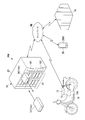
- FIG. 1 is a diagram illustrating an overall configuration of a battery lending system 10 (calculation system) according to the embodiment.
- the battery lending system 10 includes a saddle-ride type motorcycle 12 (saddle-ride type vehicle, electric vehicle), a detachable battery 14 (battery), a charging station 16 (charging device), and a management server 18 ( Server) and the mobile terminal 28.
- the detachable battery 14 is a cassette-type power storage device that is detachably attached to the motorcycle 12 that can run at least with electric power.
- the detachable battery 14 is provided by rental, and the user borrows it at the charging station 16 and mounts it on the motorcycle 12.
- the detachable battery 14 that needs to be charged may be distinguished from the “used battery 14u”, and the detachable battery 14 that has been charged may be distinguished from the “charged battery 14c”.
- At least one detachable battery 14 is mounted on one motorcycle 12.
- the detachable battery 14 has a storage unit 144.
- the storage unit 144 of the detachable battery 14 stores power consumption calculation parameter information (mileage, battery energy usage) and classification information (date and time) in association with user identification information (user ID). . Data stored in the removable battery 14 and the storage unit 144 will be described later.
- the charging station 16 is a facility for storing and charging one or more detachable batteries 14, and is installed at a plurality of locations.
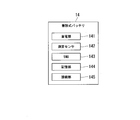
- the housing 20 of the charging station 16 is provided with a slot portion 21 composed of a plurality of (12 in the example of FIG. 1) slots, a display 161 and an authentication device 162.
- the charging station 16 is communicably connected to a management server 18 via a network NW.
- the network NW is a wireless communication network or a wired communication network.
- a charger 163 (FIG. 4) capable of charging the detachable battery 14 and a connection portion 164 (FIG. 4) are provided behind the slot 21.
- the management server 18 manages the battery lending system 10.
- the management server 18 stores electricity consumption information in association with the user ID.
- the power consumption (power consumption rate) indicates the amount of energy used per traveling distance (Wh / km).
- the user ID and the power consumption calculation parameter information are stored in the storage 144 of the used battery 14u inserted into the slot 21. (Driving distance, battery energy usage) and classification information (date and time) are read, and these information are transmitted from the charging station 16 to the management server 18.
- the management server 18 calculates the power consumption for each user from the information, and updates the power consumption information. Then, the management server 18 transmits the power consumption information for each user to the charging station 16.
- the electricity consumption information is based on the classification information (date and time), and for each period in which the user's behavior pattern and temperature are similar (every day, every weekday / holiday, every time zone, every season, every month, etc.). ).
- the user uses the motorcycle 12 for commuting, and on a holiday, uses the motorcycle 12 for entertainment. Even when the same user uses the same motorcycle 12, it is considered that the power consumption is different between when the same user uses the same motorcycle 12 and when it is used for commuting.
- the outside air temperature affects the performance of the detachable battery 14, and that the power consumption is significantly different between a low temperature winter season and a high temperature summer season.
- the charging station 16 stores information on the battery capacity and the state of deterioration of the removable battery 14 held by the charging station 16.
- the charging station 16 calculates the travelable distance for each user from the power consumption for each user for the available charged battery 14 c.
- the usable charged battery 14c is a detachable battery 14 which has been charged in the slot 21 of the charging station 16 and is ready to be lent to the user.
- the charging station 16 displays on the display 161 the travelable distance and the rental fee for each available charged battery 14c. At this time, the fairness of the fee can be maintained by setting the rental fee according to the possible travel distance.
- the fairness of the charge can be maintained by lowering the rental fee than the charged battery 14c having a long travelable distance.
- the user looks at the display on the display 161, selects a desired one from the available charged batteries 14c according to the travel plan, and attaches the selected charged battery 14c to the motorcycle 12.
- the mobile terminal 28 is a terminal carried by the user, and is, for example, a smartphone, a tablet terminal, a notebook computer, or the like. The user can operate the portable terminal 28 to obtain information about the removable battery 14 and the chargeable charging station 16.
- FIG. 2 is a diagram illustrating a configuration example of the detachable battery 14 according to the present embodiment.
- the detachable battery 14 includes a power storage unit 141, a measurement sensor 142, a BMU 143, a storage unit 144, and a connection unit 145.
- the power storage unit 141 is, for example, any one of a secondary battery, a lead storage battery, a capacitor, a lithium ion battery, and the like.
- the measurement sensor 142 includes various sensors that measure current, voltage, and temperature.
- the BMU 143 is a battery management unit (Battery Management Unit), and controls charging and power supply to the power storage unit 141.
- the storage unit 144 stores various types of information.
- the storage unit 144 is, for example, a memory.
- the connection unit 145 is connected to a connection unit (not shown) of the motorcycle 12 and a connection unit 164 of the charging station 16 to input and output power and information.
- FIG. 3 is a diagram illustrating an example of a data structure of the storage unit 144 of the detachable battery 14 according to the present embodiment.
- the storage unit 144 stores identification information of the detachable battery 14 (hereinafter, battery ID). Then, when the user borrows the detachable battery 14, the user ID indicating the borrowed user is stored in association with the battery ID. Then, while the user borrows the detachable battery 14, information on the travel distance obtained from the vehicle CAN (Controller Area Network) information and the information on the amount of battery energy used detected by the measurement sensor 142 are stored as power consumption calculation parameter information. You. Further, a date and a time are stored as the classification information.
- vehicle CAN Controller Area Network
- FIG. 4 is a diagram illustrating a configuration example of the charging station 16 according to the present embodiment.
- the charging station 16 includes a display 161, an authenticator 162, a charger 163, a connection unit 164, a communication unit 165, a storage unit 166, and a control unit 167.
- the display 161 is one of a liquid crystal display, an organic EL (Electro Luminescence) display, an electronic ink display, and the like.
- the display 161 displays information output by the control unit 167. In this embodiment, when the user borrows the battery, the display 161 displays, for each user, the charged battery 14c that can be used, the travelable distance of each charged battery 14c, and the rental fee. .
- the authenticator 162 is a device that reads record information of an NFC card (not shown) carried by the user using, for example, near field communication (NFC; Near Field Communication).
- NFC Near Field Communication
- the charger 163 is a device that charges the detachable battery 14 under the control of the control unit 167 while the connection unit 145 of the detachable battery 14 and the connection unit 164 of the charging station 16 are connected.
- a power supply (not shown) for supplying power to the detachable battery 14 is connected to the charger 163.
- the connection unit 164 is a connection unit with the connection unit 145 of the detachable battery 14, and supplies power and transmits and receives information.
- the connection unit 164 acquires the user ID output from the detachable battery 14, the power consumption calculation parameter information (mileage, battery energy usage), and the classification information (date and time), and sends the acquired information to the control unit 167. Output.
- the communication unit 165 transmits the user ID, the power consumption calculation parameter information (distance traveled, battery energy usage), and the classification information (date and time) read from the detachable battery 14 to the management server 18 via the network NW.
- the communication unit 165 receives the power consumption information for each user transmitted by the management server 18 and outputs the received power consumption information for each user to the control unit 167.
- the storage unit 166 stores a program that causes the control unit 167 to execute a process.
- the storage unit 166 stores information on the detachable batteries 14 inserted into the slot unit 21 and information on the state of charge and deterioration of each detachable battery 14.
- the control unit 167 functions as a charge control unit 1671, a measurement sensor 1672, an information acquisition unit 1673, and a calculation unit 1674 by reading and executing the program stored in the storage unit 166.
- the charging control unit 1671 controls charging of the removable battery 14 inserted in the slot unit 21.
- the measurement sensor 1672 acquires information of a current sensor, a voltage sensor, a temperature sensor, and the like. From the detection value of the measurement sensor 1672, the battery capacity and the state of deterioration of the removable battery 14 inserted in the slot 21 can be determined.
- the charge control unit 1671 performs charge control according to the detection value of the measurement sensor 1672.
- the information acquisition unit 1673 acquires information output from the detachable battery 14 connected to the connection unit 164, and causes the storage unit 166 to store the acquired information.
- the calculation unit 1674 performs various calculations. In the present embodiment, the information acquisition unit 1673 acquires the power consumption information for each user returned from the management server 18.
- the calculation unit 1674 can use the battery capacity and the deterioration state (for example, average voltage) of each detachable battery 14 obtained by the measurement sensor 1672 and the power consumption information for each user obtained from the management server 18. The travelable distance for each user is calculated for the charged battery 14c.
- FIG. 5 is a diagram illustrating a configuration example of the management server 18 according to the present embodiment.
- the management server 18 includes a communication unit 181, a storage unit 182, and a control unit 183.
- the control unit 183 includes an information acquisition unit 1831 and a calculation unit 1832 (power consumption calculation unit, distance calculation unit).
- the communication unit 181 receives the user ID, the power consumption calculation parameter information (mileage, battery energy usage), and the classification information (date and time) transmitted by the charging station 16.
- the communication unit 181 transmits the power consumption information for each user calculated by the calculation unit 1832 to the mobile terminal 28 via the network NW.
- the information acquisition unit 1831 acquires a user ID, power consumption calculation parameter information (mileage, battery energy usage), and classification information (date and time) from the information received by the communication unit 181.
- the operation unit 1832 calculates, for each power consumption calculation condition, the user ID acquired by the information acquisition unit 1831, the electricity consumption calculation parameter information (mileage, battery energy usage), and the classification information (date and time). Calculate the power consumption for each user.
- the storage unit 182 includes, for example, a storage device such as a hard disk built in or external to the computer system.
- the electricity consumption information for each user obtained by the calculation unit 1832 is recorded in the storage unit 182.
- FIG. 6 is a diagram illustrating an example of a data structure of the electricity consumption information stored in the storage unit 182 of the management server 18 according to the present embodiment.
- the storage unit 182 stores power consumption information of each user in association with the user ID.
- the power consumption information is obtained by classifying the power consumption information into periods and temperatures (each day of the week, weekdays / holidays, each time zone, each season, every month, etc.) based on the classification information (date and time). And stored in the storage unit 182.
- the power consumption of each user is obtained by classifying each day of the week, weekday / holiday, time zone, season, and month, it is not necessary to classify all.
- the power consumption of the user may be obtained by classifying only the weekdays / holidays.
- FIG. 7 is a flowchart showing a battery replacement procedure in the battery lending system 10 according to the present embodiment.
- Step L1 The replacement work of the detachable battery 14 is started.
- Step S1 When using the motorcycle 12, the user borrows the detachable battery 14 (charged battery 14c).
- Step S2 When the detachable battery 14 is lent, the user ID indicating the borrowed user is stored in the storage unit 144 of the detachable battery 14, as shown in FIG.
- Step S3 During the operation of the motorcycle 12 with the detachable battery 14 attached to the motorcycle 12, the power consumption calculation parameter information (travel distance, battery energy usage) and the classification information (date and time) are The acquired information is stored in the storage unit 144 of the removable battery 14 in association with the user ID as shown in FIG.
- Step S4 The user removes the detachable battery 14 (used battery 14u) from the motorcycle 12, and returns it to the slot 21 of the charging station 16.
- Step S5 Upon detecting that the detachable battery 14 has been returned to the slot unit 21, the control unit 167 of the charging station 16 reads the user ID and the electricity consumption calculation parameter information (the traveling distance) from the storage unit 144 of the detachable battery 14. , Battery energy usage) and classification information (date and time), and transmit them to the management server 18.
- the control unit 167 of the charging station 16 Upon detecting that the detachable battery 14 has been returned to the slot unit 21, the control unit 167 of the charging station 16 reads the user ID and the electricity consumption calculation parameter information (the traveling distance) from the storage unit 144 of the detachable battery 14. , Battery energy usage) and classification information (date and time), and transmit them to the management server 18.
- Step S6 the calculation unit 1832 of the management server 18 calculates the power consumption for each user using the power consumption calculation parameter information (the mileage and the amount of battery energy used).
- the power consumption is calculated based on the classification information (date and time) based on the period and the temperature in which the behavior pattern is similar (every day of the week, weekday / holiday, every time zone, every season, every month, etc.).
- the user's electricity cost can be calculated as follows.
- the storage unit 182 of the management server 18 stores power consumption information of each user up to the previous time. In the initial state, an average value is stored as power consumption information of the user. As the user repeatedly exchanges the detachable battery 14, the process of step S6 is repeated, and the power consumption information of each user is updated.
- Step S7 The management server 18 transmits the user electricity consumption information of the user to the charging station 16.
- Step S8 When the calculation unit 1674 of the charging station 16 receives the user power consumption information, the calculation unit 1674 can use the received user power consumption information and the battery capacity and the average voltage of the removable battery 14 stored in the storage unit 166.
- the travelable distance of the detachable battery 14 is calculated.
- the electricity cost information is calculated by classifying each day of the week, weekday / holiday, time zone, season, month, and the like, and the calculating unit 1674 of the charging station 16 uses the electricity cost information suitable for the current environment among them. To calculate the possible travel distance. For example, when renting a battery on a holiday, the travelable distance is calculated using the electricity consumption information of the user on the holiday.
- the travelable distance (AER: All @ Electric @ Range) can be calculated as follows.
- Driving distance (AER) (battery capacity x average voltage) / user's power consumption
- the available battery capacity and average voltage of each removable battery 14 are measured by the measurement sensor 1672 of the charging station 16 and stored in the storage unit 166.
- the battery capacity and the average voltage are the same for the same type of battery, but vary depending on the state of charge and the influence of deterioration.
- Step S9 After calculating the travelable distance for each user, the charging station 16 displays the travelable distance and the rental fee for each user for the available charged battery 14c. As will be described later, the rental fee can present a fair price in accordance with the power consumption of each user and the state of deterioration of the detachable battery 14.
- Step L2 The replacement of the removable battery 14 is completed.
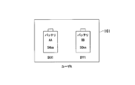
- FIG. 8A and 8B are diagrams showing the display of the mileage for each user displayed on the display 161 of the charging station 16 according to the present embodiment.
- FIG. 8A is a display for the user A.
- FIG. 8B is a display for the user B.
- two batteries, a battery “AA” and a battery “BB” are available charged batteries 14c. Even with the same charged battery 14c, the capacity of each battery varies depending on the deterioration of the battery.
- the battery capacity of battery “AA” is larger than the battery capacity of battery “BB”.
- the battery “AA” and the battery “BB” are presented as available charged batteries 14c.
- the mileage is displayed as “54 km”, and the rental fee is displayed as “$ XX1”.
- the mileage is displayed as “50 km” and the rental fee is displayed as “$ YY1”.
- the user A refers to the travelable distance and the rental fee to select and rent one of the battery “AA” and the battery “BB”.
- the difference in the lending fee between the battery “AA” and the battery “BB” is due to the difference in the mileage.
- the battery “AA” has a longer travelable distance than the battery “BB”, and thus the rental fee “$ XX1” is set to be slightly higher than the rental fee “$ YY1”.
- the user can select a battery according to how long the traveling distance of the motorcycle 12 to travel will be. That is, if the traveling distance is short, the rental fee can be reduced by selecting the battery “BB”. If the traveling distance is long, selecting the battery "AA” allows the vehicle to travel over a long distance with confidence.
- the battery “AA” and the battery “BB” are presented as available charged batteries 14c.
- the mileage is displayed as “59 km” and the rental fee is displayed as “$ XX2”
- the rental fee is displayed as “$ YY2”.
- the user B selects and borrows either the battery “AA” or the battery “BB” with reference to the travelable distance and the rental fee.
- the difference is caused by the difference in power consumption for each user. Since the user B has a better power consumption than the user A, the travelable distance is longer.
- the user B can select a battery according to how long the traveling distance of the motorcycle 12 to be traveling will be. Since the travelable distance displayed at this time is calculated according to the day of the week, weekday / holiday, time zone, season, month, and the like for each user, the reliability is high.
- the traveling distance of the user B is calculated based on the lending fee at the traveling distance unit price of the user A. Lending fee at unit price is low. That is, the lending fee ($ XX1 and $ YY1) when user A borrows batteries "AA” and "BB” and the lending fee ($ XX2 and $ XX) when user B borrows batteries "AA” and "BB". Even if YY2) is the same, user B can run a longer distance than user A, and accordingly, the rental fee per travel distance of user B is lower.
- the user can know a highly accurate travelable distance, and can select and borrow a desired battery from a plurality of available charged batteries 14c. Thereby, the user can select the optimal removable battery 14 according to the usage plan. Further, in the present embodiment, by setting the rental fee according to the travelable distance, the deterioration state of the battery can be reflected on the rental fee. As a result, the fairness of the rental fee can be maintained.
- the power consumption calculation parameter information (distance traveled, battery energy usage) and classification information (date and time) for each user are transmitted from the charging station 16 to the management server 18, but the motorcycle 12 has a communication function.
- the TCU may transmit such information to the management server 18 at a predetermined time or at a predetermined time interval.
- the process of calculating the possible travel distance from the electricity consumption information is performed by the calculation unit 1674 of the charging station 16; however, the process of calculating the possible travel distance from the electricity consumption information is performed by the calculation unit 1832 ( Distance calculation unit).
- the available travel distance and the rental fee for each user are displayed on the display 161 of the management server 18 for the available charged battery 14c.
- the rental fee may be displayed.
- FIG. 9 is a diagram showing an overall configuration of a battery lending system 10A according to a modification of the embodiment.
- the motorcycle 12 includes a TCU having a communication function.
- the calculation unit 1832 of the management server 18 performs the process of calculating the possible travel distance from the electricity cost information.
- the travelable distance and the rental fee for each user are displayed on the display unit 2801 of the portable terminal 28.
- the battery lending system 10A includes a saddle-ride type motorcycle 12 (saddle-ride type vehicle), a TCU 13, a detachable battery 14 (battery), a charging station 16, a management server 18, and a portable terminal 28. Including. Components having the same functions as those of the battery lending system 10 are denoted by the same reference numerals, and description thereof is omitted.
- the TCU 13 is a communication unit mounted in the motorcycle 12.
- the TCU 13 obtains the user ID, the power consumption calculation parameter information (mileage, battery energy usage), and the classification information (date and time) stored in the storage unit 144 of the detachable battery 14, and transmits the obtained information to the network NW.
- the transmission timing is, for example, a predetermined time or a predetermined time interval (for example, every one minute).
- the control unit 183 (FIG. 5) of the management server 18 transmits the user ID, the power consumption calculation parameter information (mileage, battery energy usage), and the classification information (date and time) from the TCU 13 via the communication unit 181 (FIG. 5). To receive. Then, the arithmetic unit 1832 of the management server 18 calculates the day of the week, weekday / holiday, time zone, season, month, etc. based on the electricity consumption calculation parameter information (travel distance, battery energy usage) based on the classification information (date and time). For each user, the power consumption of each user is calculated.
- the user can reserve the battery using the portable terminal 28 when replacing the removable battery 14.
- the user sends a user ID to be authenticated, and connects the mobile terminal 28 to the management server 18. Then, the user operates the portable terminal 28 to select the charging station 16 desired to be replaced.
- the management server 18 stores a database for managing information on the detachable batteries 14 of each charging station 16 (battery ID, the number of charged batteries 14c and used batteries 14u, the battery capacity of each detachable battery 14, the state of deterioration, and the like). Have.
- the management server 18 acquires information on the charged battery 14c that can be reserved at each charging station 16 from this database, and presents it to the portable terminal 28 of each user.
- the operation unit 1832 of the management server 18 calculates the possible travel distance for each user for the charged battery 14c that can be reserved at the charging station 16 that is desired to be replaced, from the power consumption information for each user and the information in the database.
- the portable terminal 28 displays the travelable distance and the rental fee for each user on the display unit 2801 for the charged battery 14c that can be reserved at the charging station 16 where replacement is desired.
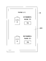
- FIG. 10 is a diagram showing a display example of the display unit 2801 of the portable terminal 28 according to the modification.
- the display unit 2801 of the portable terminal 28 displays the travelable distance and the rental fee for each user for the charged battery 14 c that can be reserved at the charging station 16 where the replacement is desired.
- the battery “AA” and the battery “BB” are presented as the charged battery 14c that can be reserved by the user.
- the mileage is displayed as “54 km”
- the rental fee is displayed as “$ XX1”.
- the battery “BB” the mileage is displayed as “50 km” and the rental fee is displayed as “$ YY1”.
- One embodiment of the present invention is a battery rental system 10 in which a charging station 16 for storing and charging a detachable battery 14 is installed, and the detachable battery 14 is rented at the charging station 16 and mounted on a motorcycle 12.
- a storage unit 144 for storing the power consumption calculation parameter information for obtaining the power consumption for each user in association with the user; and acquiring the power consumption calculation parameter information stored in the storage unit 144 to reduce the power consumption for each user.
- a program for realizing the functions of the battery lending systems 10 and 10A in the present invention is recorded on a computer-readable recording medium, and the program recorded on the recording medium is read by a computer system and executed.
- the battery lending system 10, 10A may be realized.
- the “computer system” includes an OS and hardware such as peripheral devices.
- the “computer system” also includes a WWW system provided with a homepage providing environment (or display environment).
- the “computer-readable recording medium” refers to a portable medium such as a flexible disk, a magneto-optical disk, a ROM, and a CD-ROM, and a storage device such as a hard disk built in a computer system.
- the “computer-readable recording medium” refers to a volatile memory (RAM) inside a computer system that becomes a server or a client when a program is transmitted through a network such as the Internet or a communication line such as a telephone line. And those holding programs for a certain period of time.
- RAM volatile memory
- the program may be transmitted from a computer system storing the program in a storage device or the like to another computer system via a transmission medium or by a transmission wave in the transmission medium.
- the "transmission medium” for transmitting a program refers to a medium having a function of transmitting information, such as a network (communication network) such as the Internet or a communication line (communication line) such as a telephone line.
- the program may be for realizing a part of the functions described above.
- a difference file difference file (difference program) may be sufficient.
- 10A battery lending system (calculation system), 12: motorcycle (electric vehicle), 14: detachable battery, 16: charging station (charging device), 18: management server (server), 21: slot unit, 28 ... portable terminal, 144 ... storage unit, 161 ... display unit, 166 ... storage unit, 167 ... control unit, 1671 ... charge control unit, 1672 ... measurement sensor, 1673 ... information acquisition unit, 1674 ... calculation unit, 183 # control unit, 1831: information acquisition unit, 1832: calculation unit (power consumption calculation unit, distance calculation unit)
Landscapes
- Business, Economics & Management (AREA)
- Accounting & Taxation (AREA)
- Finance (AREA)
- Development Economics (AREA)
- Economics (AREA)
- Marketing (AREA)
- Strategic Management (AREA)
- Physics & Mathematics (AREA)
- General Business, Economics & Management (AREA)
- General Physics & Mathematics (AREA)
- Engineering & Computer Science (AREA)
- Theoretical Computer Science (AREA)
- Electric Propulsion And Braking For Vehicles (AREA)
- Management, Administration, Business Operations System, And Electronic Commerce (AREA)
- Secondary Cells (AREA)
Abstract
算出システムは、着脱式バッテリが装着される電動車両のユーザ毎の電力消費率である電費を算出するための電費算出パラメータ情報をユーザに対応付けて記憶する記憶部と;記憶部に記憶されている電費算出パラメータ情報を取得してユーザ毎の電費を算出する管理サーバと;を備え、管理サーバで算出されたユーザ毎の電費を用いて、着脱式バッテリを装着して電動車両が走行可能なユーザ毎の走行可能距離を算出する。
Description
本発明は、算出システム、算出方法、及びサーバに関する。
本願は、2018年7月31日に出願された日本国特許出願2018-143633号に基づき優先権を主張し、その内容をここに援用する。
本願は、2018年7月31日に出願された日本国特許出願2018-143633号に基づき優先権を主張し、その内容をここに援用する。
電動車両の駆動源であるバッテリ(電池)を着脱式にして、複数のユーザで共同利用するシェアサービスが知られている。このようなシェアサービスでは、1つ以上の着脱式バッテリの保管および充電を行う充電ステーションが各地に設置されている。走行によりバッテリの残量が減少すると、ユーザは充電ステーションで使用済みバッテリを充電済みバッテリに交換する。このようなシェアサービスでは、1箇所の充電ステーションに、劣化状態の異なる着脱式バッテリが混在することになる。
バッテリの劣化状態の判定については、特許文献1に、電動車両に搭載されるリチウムイオン電池において、劣化に伴う電池特性の変化を検知する技術が記載されている。電動車両に着脱自在のバッテリを搭載することについては、特許文献2に、電気スクーターの座面の下に配置されたコンパートメントに出し入れするような蓄電装置で、発火のリスクを軽減するようにしたものが記載されている。
このようなシェアサービスを利用する場合の課金としては、年額や月額の定額制ということが考えられる。ところが、定額制の課金は、サービスを長期的に利用するユーザにとっては利便性が高いが、サービスを試してみたいユーザや、観光地等でサービスを一時的利用するようなユーザにとっては、利用しにくい。そこで、バッテリを1回毎にレンタルとし、バッテリを交換する毎にバッテリ貸出料金として課金することが考えられる。
しかしながら、上述のように、1箇所の充電ステーションには、劣化状態の異なる着脱式バッテリが混在する。定額制の課金の場合には、何回バッテリを交換しても同一料金のため、どのような状態のバッテリに交換しても、ユーザに不公平感を与えることはない。
ところが、バッテリを交換する毎に課金を行う場合には、劣化のないバッテリを借り受けたユーザと劣化の進んだバッテリを借り受けたユーザとの間で不公平感が生じる。
ところが、バッテリを交換する毎に課金を行う場合には、劣化のないバッテリを借り受けたユーザと劣化の進んだバッテリを借り受けたユーザとの間で不公平感が生じる。
そこで、ユーザがバッテリを借り受ける際に、バッテリの性能をユーザに提示して、バッテリを選択できるようにすることが考えられる。しかしながら、バッテリの性能の指標として、例えばバッテリ残量(Wh)を提示されても、ユーザは、そのバッテリの性能がどの程度であるかを認識することが難しい。
バッテリの性能の指標として、走行可能距離を提示することも考えられる。バッテリの性能の指標として走行可能距離が提示されれば、ユーザは、走行計画に合わせて、バッテリを選択することができる。しかしながら、走行可能距離は、バッテリの性能とともに、ユーザ毎の電費の影響を大きく受ける。すなわち、一般走行をするユーザと、スポーツ走行をするユーザとでは、電費が大きく異なる。また、同一のユーザであっても、通勤に使用する場合と娯楽に使用する場合とでは、電費は異なる。
本発明の態様は、バッテリの使用料金の公平性を保つことができるとともに、精度の高い走行可能距離を提示できる算出システムを提供する。
(1)本発明の一態様に係る算出システムは、着脱式バッテリが装着される電動車両のユーザ毎の電力消費率である電費を算出するための電費算出パラメータ情報を前記ユーザに対応付けて記憶する記憶部と;前記記憶部に記憶されている電費算出パラメータ情報を取得して前記ユーザ毎の電費を算出する管理サーバと;を備え、前記管理サーバで算出された前記ユーザ毎の電費を用いて、前記着脱式バッテリを装着して前記電動車両が走行可能な前記ユーザ毎の走行可能距離を算出する。
(2)上記算出システムでは、前記電費算出パラメータ情報は、前記電動車両の走行距離と前記着脱式バッテリのエネルギー使用量の情報であってもよい。
(3)上記算出システムでは、前記記憶部は、さらに、前記ユーザの行動パターンや気温が類似する期間を分類するための分類情報を記憶してもよい。
(4)上記算出システムでは、前記着脱式バッテリを前記ユーザに使用させる場合に、前記ユーザに提示する使用料金を前記ユーザ毎に算出してもよい。
(5)上記算出システムでは、前記ユーザ毎の前記使用料金は、前記ユーザ毎の前記走行可能距離に応じて設定されてもよい。
(6)上記算出システムでは、前記記憶部に記憶されている電費算出パラメータ情報は、前記着脱式バッテリが充電装置に装着される時に前記記憶部から前記充電装置に送られ、前記充電装置から前記管理サーバに送られてもよい。
(7)上記算出システムでは、前記記憶部に記憶されている電費算出パラメータ情報は、通信機能により前記記憶部から前記管理サーバに送信されてもよい。
(8)上記算出システムでは、前記ユーザ毎の走行可能距離は、前記着脱式バッテリを充電する充電装置の表示部に表示されてもよい。
(9)上記算出システムでは、前記ユーザ毎の走行可能距離は、前記管理サーバと通信機能により接続される携帯端末の表示部に表示されてもよい。
(10)本発明の別の一態様に係る算出方法は、記憶部が、着脱式バッテリが装着される電動車両のユーザ毎の電力消費率である電費を算出するための電費算出パラメータ情報を前記ユーザに対応付けて記憶するステップと;管理サーバが、前記記憶部に記憶されている電費算出パラメータ情報を取得して前記ユーザ毎の電費を算出するステップと;前記管理サーバで算出された前記ユーザ毎の電費を用いて、前記着脱式バッテリを装着して前記電動車両が走行可能な前記ユーザ毎の走行可能距離を算出するステップと;を含む。
(11)本発明のさらに別の一態様に係るサーバは、着脱式バッテリが装着される電動車両のユーザ毎の電力消費率である電費を算出するための電費算出パラメータ情報を取得して前記ユーザ毎の電費を算出する電費算出部と;前記電費算出部で算出された前記ユーザ毎の電費を用いて、前記着脱式バッテリを装着して前記電動車両が走行可能な前記ユーザ毎の走行可能距離を算出する距離算出部と;を備える。
上述した(1)、(10)、(11)によれば、ユーザ毎の精度の高い走行可能距離を提示できるので、ユーザの走行計画に応じた最適なバッテリを選択することができる。
上述した(2)によれば、電動車両の走行距離と着脱式バッテリのエネルギー使用量の情報を用いることで、ユーザ毎の電費を算出できる。
上述した(3)によれば、分類情報を用いることで、ユーザの行動パターンや気温毎に各ユーザの電費が算出でき、電費情報の精度の向上が図れる。
上述した(3)によれば、分類情報を用いることで、ユーザの行動パターンや気温毎に各ユーザの電費が算出でき、電費情報の精度の向上が図れる。
上述した(4)によれば、ユーザ毎の使用料金が算出されるので、使用料金に応じて、最適なバッテリを選択できる。
上述した(5)によれば、ユーザ毎の使用料金が算出されるので、バッテリの使用料金の公平性を保つことができる。
上述した(5)によれば、ユーザ毎の使用料金が算出されるので、バッテリの使用料金の公平性を保つことができる。
上述した(6)によれば、記憶部に記憶されている電費算出パラメータ情報を、着脱式バッテリが充電装置に装着される時に、充電装置で読み取り、充電装置から算出システムを管理する管理サーバに送信することができる。
上述した(7)によれば、記憶部に記憶されている電費算出パラメータ情報を、通信機能により、適宜、管理サーバに送信することができる。
上述した(7)によれば、記憶部に記憶されている電費算出パラメータ情報を、通信機能により、適宜、管理サーバに送信することができる。
上述した(8)によれば、ユーザは、充電装置に着脱式バッテリを装着する際に、利用可能な充電済みバッテリについて、走行可能距離を知ることができる。
上述した(9)によれば、ユーザは、バッテリ予約時等に、利用可能な充電済みバッテリについて、走行可能距離を知ることができる。
上述した(9)によれば、ユーザは、バッテリ予約時等に、利用可能な充電済みバッテリについて、走行可能距離を知ることができる。
以下、本発明の実施形態に係るバッテリ貸出しシステムについて添付の図面を参照しながら説明する。
[全体構成]
図1は、実施形態におけるバッテリ貸出しシステム10(算出システム)の全体構成を示す図である。
図1に示すように、バッテリ貸出しシステム10は、鞍乗り型の自動二輪車12(鞍乗型車両、電動車両)、着脱式バッテリ14(電池)、充電ステーション16(充電装置)、管理サーバ18(サーバ)、および携帯端末28を含む。
図1は、実施形態におけるバッテリ貸出しシステム10(算出システム)の全体構成を示す図である。
図1に示すように、バッテリ貸出しシステム10は、鞍乗り型の自動二輪車12(鞍乗型車両、電動車両)、着脱式バッテリ14(電池)、充電ステーション16(充電装置)、管理サーバ18(サーバ)、および携帯端末28を含む。
着脱式バッテリ14は、少なくとも電力により走行可能な自動二輪車12に対して着脱自在に装着されるカセット式の蓄電装置である。本実施形態では、着脱式バッテリ14はレンタルで提供されており、ユーザが充電ステーション16で借り受けて自動二輪車12に装着する。以下、説明の便宜上、充電が必要になった着脱式バッテリ14を「使用済みバッテリ14u」、充電が完了した着脱式バッテリ14を「充電済みバッテリ14c」と区別する場合がある。着脱式バッテリ14は、1つの自動二輪車12に少なくとも1つが搭載されている。着脱式バッテリ14は、記憶部144を有している。着脱式バッテリ14の記憶部144には、ユーザ識別情報(ユーザID)と対応付けて、電費算出パラメータ情報(走行距離、バッテリエネルギー使用量)と、分類情報(日付および時間)とが記憶される。着脱式バッテリ14や記憶部144に記憶されるデータについては後述する。
充電ステーション16は、1つ以上の着脱式バッテリ14の保管および充電を行うための設備であり、複数の場所に設置されている。充電ステーション16の筐体20には、複数個(図1の例では12個)のスロットからなるスロット部21と、表示器161と、認証器162とが設けられている。充電ステーション16は、ネットワークNWを介して、管理サーバ18と通信可能に接続されている。ネットワークNWは、無線通信網または有線通信網である。スロット部21の奥側には、着脱式バッテリ14を充電可能な充電器163(図4)と、接続部164(図4)が設けられている。
管理サーバ18は、バッテリ貸出しシステム10の管理を行っている。本実施形態では、管理サーバ18は、ユーザIDと対応付けて電費情報を記憶している。電費(電力消費率)とは、走行距離あたりの使用エネルギー量(Wh/km)を示す。ユーザが使用済みバッテリ14uを充電ステーション16のスロット部21に挿入してバッテリの返却を行うと、スロット部21に挿入された使用済みバッテリ14uの記憶部144から、ユーザIDと、電費算出パラメータ情報(走行距離、バッテリエネルギー使用量)と、分類情報(日付および時間)が読み出され、これらの情報が充電ステーション16から管理サーバ18に送信される。管理サーバ18は、充電ステーション16からの情報を受信すると、これらの情報から、ユーザ毎の電費を計算し、電費情報を更新する。そして、管理サーバ18は、ユーザ毎の電費情報を充電ステーション16に送信する。
後に説明するように、電費情報は、分類情報(日付および時間)を基に、ユーザの行動パターンや気温が類似する期間毎(曜日毎、平日/休日、時間帯毎、季節毎、月毎等)に分類して求められる。これは、ユーザの行動パターンや気温は、電費に大きな影響を与えると考えられるからである。例えば、平日ならユーザは通勤に自動二輪車12を使用し、休日なら娯楽に自動二輪車12を使用する。同一のユーザが同一の自動二輪車12を使用する場合であっても、通勤に使用するときと娯楽に使用するときとでは、電費は異なると考えられる。また、外気温が着脱式バッテリ14の性能に影響を与え、気温の低い冬場と、気温の高い夏場とでは、電費が大きく異なることが知られている。
充電ステーション16は、充電ステーション16が保有している着脱式バッテリ14のバッテリ容量や劣化状態の情報を記憶している。充電ステーション16は、管理サーバ18から、ユーザ毎の電費情報を取得すると、利用可能な充電済みバッテリ14cについて、ユーザ毎の電費からユーザ毎の走行可能距離を算出する。利用可能な充電済みバッテリ14cとは、充電ステーション16のスロット部21内で充電が完了しており、ユーザに貸し出しできる状態にある着脱式バッテリ14である。そして、充電ステーション16は表示器161に、利用可能な充電済みバッテリ14c毎に、走行可能な距離と貸出料金を表示して提示する。このとき、走行可能距離に応じて貸出料金を設定することで、料金の公平性を保つことができる。すなわち、走行可能距離が短い充電済みバッテリ14cの場合には、走行可能距離が長い充電済みバッテリ14cより貸出料金を下げることで、料金の公平性が保てる。ユーザは、表示器161の表示を見て、走行計画に合わせて、利用可能な充電済みバッテリ14cの中から所望のものを選択し、選択した充電済みバッテリ14cを自動二輪車12に装着する。
携帯端末28は、ユーザが携行する端末であり、例えばスマートフォン、タブレット端末、ノートパソコン等である。ユーザは携帯端末28を操作して、着脱式バッテリ14や貸し出し可能な充電ステーション16についての情報を取得することができる。
[着脱式バッテリ14の構成]
次に、着脱式バッテリ14の構成例を説明する。
図2は、本実施形態に係る着脱式バッテリ14の構成例を示す図である。図2に示すように、着脱式バッテリ14は、蓄電部141、測定センサ142、BMU143、記憶部144、および接続部145を備える。
次に、着脱式バッテリ14の構成例を説明する。
図2は、本実施形態に係る着脱式バッテリ14の構成例を示す図である。図2に示すように、着脱式バッテリ14は、蓄電部141、測定センサ142、BMU143、記憶部144、および接続部145を備える。
蓄電部141は、例えば、二次電池や鉛蓄電池やキャパシタやリチウムイオン電池等のいずれか1つである。測定センサ142は、電流や電圧、温度を測定する各種センサから構成されている。BMU143は、バッテリマネージメントユニット(Battery Management Unit)であり、蓄電部141への充電や給電を制御する。記憶部144には、各種の情報が記憶される。記憶部144は、例えば、メモリである。接続部145は、自動二輪車12の接続部(不図示)や充電ステーション16の接続部164と接続して、電力や情報の入出力を行う。
[記憶部144のデータ構造]
図3は、本実施形態に係る着脱式バッテリ14の記憶部144のデータ構造の一例を示す図である。記憶部144には、着脱式バッテリ14の識別情報(以下、バッテリID)が記憶されている。そして、ユーザが着脱式バッテリ14を借り受けると、バッテリIDに対応付けて、借り受けたユーザを示すユーザIDが記憶される。そして、ユーザが着脱式バッテリ14を借り受けている間、車両CAN(Controller Area Network)情報から取得された走行距離や測定センサ142で検出されたバッテリエネルギー使用量の情報が電費算出パラメータ情報として記憶される。また、分類情報として、日付および時間が記憶される。
図3は、本実施形態に係る着脱式バッテリ14の記憶部144のデータ構造の一例を示す図である。記憶部144には、着脱式バッテリ14の識別情報(以下、バッテリID)が記憶されている。そして、ユーザが着脱式バッテリ14を借り受けると、バッテリIDに対応付けて、借り受けたユーザを示すユーザIDが記憶される。そして、ユーザが着脱式バッテリ14を借り受けている間、車両CAN(Controller Area Network)情報から取得された走行距離や測定センサ142で検出されたバッテリエネルギー使用量の情報が電費算出パラメータ情報として記憶される。また、分類情報として、日付および時間が記憶される。
[充電ステーション16の構成]
次に、充電ステーション16の構成例を説明する。
図4は、本実施形態に係る充電ステーション16の構成例を示す図である。図4に示すように、充電ステーション16は、表示器161、認証器162、充電器163、接続部164、通信部165、記憶部166、および制御部167を備える。
次に、充電ステーション16の構成例を説明する。
図4は、本実施形態に係る充電ステーション16の構成例を示す図である。図4に示すように、充電ステーション16は、表示器161、認証器162、充電器163、接続部164、通信部165、記憶部166、および制御部167を備える。
表示器161は、液晶表示装置、有機EL(Electro Luminescence)表示装置、電子インク表示装置等のいずれか1つである。表示器161は、制御部167が出力する情報を表示する。本実施形態では、表示器161には、ユーザがバッテリの貸出しを受ける際に、ユーザ毎に、利用可能な充電済みバッテリ14cと、各充電済みバッテリ14cの走行可能距離と貸出料金が表示される。
認証器162は、例えば近距離通信(NFC;Near Field Communication)を用いてユーザが携行するNFCカード(不図示)の記録情報を読み取る機器である。
充電器163は、着脱式バッテリ14の接続部145と、充電ステーション16の接続部164とを接続した状態下に着脱式バッテリ14を制御部167の制御に応じて充電する機器である。充電器163には、着脱式バッテリ14に電力を供給するための電源(不図示)が接続されている。
接続部164は、着脱式バッテリ14の接続部145との接続部であり、電力の供給と、情報の送受信を行う。接続部164は、着脱式バッテリ14が出力するユーザIDと、電費算出パラメータ情報(走行距離、バッテリエネルギー使用量)と、分類情報(日付および時間)を取得し、取得した情報を制御部167に出力する。
通信部165は、着脱式バッテリ14から読み出したユーザID、電費算出パラメータ情報(走行距離、バッテリエネルギー使用量)、分類情報(日付および時間)を、ネットワークNWを介して管理サーバ18へ送信する。通信部165は、管理サーバ18が送信したユーザ毎の電費情報を受信し、受信したユーザ毎の電費情報を制御部167に出力する。
記憶部166は、制御部167に処理を実行させるプログラムを記憶する。記憶部166には、スロット部21に挿入されている着脱式バッテリ14の情報や、各着脱式バッテリ14の充電状態や劣化状態の情報が記憶されている。
制御部167は、記憶部166が記憶するプログラムを読み出し実行することで、充電制御部1671、測定センサ1672、情報取得部1673、および演算部1674として機能する。
充電制御部1671は、スロット部21に挿入されている着脱式バッテリ14の充電制御を行う。
測定センサ1672は、電流センサ、電圧センサ、温度センサ等の情報を取得する。測定センサ1672の検出値から、スロット部21に挿入されている着脱式バッテリ14のバッテリ容量や劣化状態を判定できる。充電制御部1671は、測定センサ1672の検出値に応じて、充電制御を行っている。
情報取得部1673は、接続部164に接続された着脱式バッテリ14が出力する情報を取得し、取得した情報を記憶部166に記憶させる。演算部1674は、各種の演算を行う。本実施形態では、情報取得部1673は、管理サーバ18から返されるユーザ毎の電費情報を取得する。そして、演算部1674は、測定センサ1672で求められた各着脱式バッテリ14のバッテリ容量や劣化状態(例えば平均電圧)と、管理サーバ18から取得されたユーザ毎の電費情報とから、利用可能な充電済みバッテリ14cについて、各ユーザ毎の走行可能距離を算出する。
[管理サーバ18の構成]
次に、管理サーバ18の構成例を説明する。
図5は、本実施形態に係る管理サーバ18の構成例を示す図である。図5に示すように、管理サーバ18は、通信部181、記憶部182、および制御部183を備える。制御部183は、情報取得部1831、および演算部1832(電費算出部、距離算出部)を備える。
次に、管理サーバ18の構成例を説明する。
図5は、本実施形態に係る管理サーバ18の構成例を示す図である。図5に示すように、管理サーバ18は、通信部181、記憶部182、および制御部183を備える。制御部183は、情報取得部1831、および演算部1832(電費算出部、距離算出部)を備える。
通信部181は、充電ステーション16が送信したユーザID、電費算出パラメータ情報(走行距離、バッテリエネルギー使用量)、および分類情報(日付および時間)を受信する。通信部181は、演算部1832で算出した各ユーザ毎の電費情報をネットワークNWを介して携帯端末28へ送信する。
情報取得部1831は、通信部181で受信した情報から、ユーザID、電費算出パラメータ情報(走行距離、バッテリエネルギー使用量)、および分類情報(日付および時間)を取得する。
演算部1832(電費算出部)は、情報取得部1831で取得したユーザID、電費算出パラメータ情報(走行距離、バッテリエネルギー使用量)、および分類情報(日付および時間)から、電費算出条件毎に、ユーザ毎の電費を算出する。
記憶部182は、例えば、コンピュータシステムに内蔵または外付けされるハードディスク等の記憶装置から構成される。演算部1832で求められたユーザ毎の電費情報は、記憶部182に記録される。
<電費情報のデータ構造>
図6は、本実施形態に係る管理サーバ18の記憶部182に記憶される電費情報のデータ構造の一例を示す図である。図6に示すように、記憶部182には、ユーザIDに対応付けて、各ユーザの電費情報が記憶される。電費情報は、分類情報(日付および時間)に基づいて、ユーザの行動パターンが類似する期間や気温毎(曜日毎、平日/休日、時間帯毎、季節毎、月毎等)に分類して求められ、記憶部182に記憶される。
図6は、本実施形態に係る管理サーバ18の記憶部182に記憶される電費情報のデータ構造の一例を示す図である。図6に示すように、記憶部182には、ユーザIDに対応付けて、各ユーザの電費情報が記憶される。電費情報は、分類情報(日付および時間)に基づいて、ユーザの行動パターンが類似する期間や気温毎(曜日毎、平日/休日、時間帯毎、季節毎、月毎等)に分類して求められ、記憶部182に記憶される。
この例では、曜日毎、平日/休日、時間帯毎、季節毎、月毎に分類して各ユーザの電費を求めているが、全てに分類する必要はない。例えば、平日/休日だけに分類して、ユーザの電費を求めてもよい。
[バッテリの交換手順]
図7は、本実施形態に係るバッテリ貸出しシステム10でのバッテリ交換手順を示すフローチャートである。
図7は、本実施形態に係るバッテリ貸出しシステム10でのバッテリ交換手順を示すフローチャートである。
(ステップL1)着脱式バッテリ14の交換作業を開始する。
(ステップS1)自動二輪車12の使用に際して、ユーザは着脱式バッテリ14(充電済みバッテリ14c)の貸し出しを受ける。
(ステップS2)着脱式バッテリ14の貸し出しを受けると、図3に示したように、借り受けたユーザを示すユーザIDを着脱式バッテリ14の記憶部144に記憶する。
(ステップS3)着脱式バッテリ14を自動二輪車12に装着して自動二輪車12を運転している間に、電費算出パラメータ情報(走行距離、バッテリエネルギー使用量)と、分類情報(日付および時間)が取得され、図3に示したように、これらの情報がユーザIDに対応付けて着脱式バッテリ14の記憶部144に記憶されていく。
(ステップS4)ユーザは、自動二輪車12から着脱式バッテリ14(使用済みバッテリ14u)を外し、充電ステーション16のスロット部21に返却する。
(ステップS5)充電ステーション16の制御部167は、着脱式バッテリ14がスロット部21に返却されたことを検出すると、着脱式バッテリ14の記憶部144から、ユーザID、電費算出パラメータ情報(走行距離、バッテリエネルギー使用量)、分類情報(日付および時間)を取得し、管理サーバ18へ送信する。
(ステップS6)管理サーバ18の演算部1832は、図6に示したように、電費算出パラメータ情報(走行距離、バッテリエネルギー使用量)を用いてユーザ毎の電費を算出する。電費は、分類情報(日付および時間)に基づいて、行動パターンが類似する期間や気温により分類して(曜日毎、平日/休日、時間帯毎、季節毎、月毎等)算出される。ユーザの電費は、以下のようにして計算できる。
ユーザの電費=バッテリエネルギー使用量/走行距離
なお、管理サーバ18の記憶部182には、前回までの各ユーザの電費情報が記憶されている。初期状態では、ユーザの電費情報として平均的な値が格納される。ユーザが着脱式バッテリ14の交換を繰り返していくと、ステップS6の処理が繰り返され、各ユーザの電費情報が更新されていく。
(ステップS7)管理サーバ18は、充電ステーション16に、そのユーザのユーザ電費情報を送信する。
(ステップS8)充電ステーション16の演算部1674は、ユーザ電費情報を受信すると、受信したユーザ電費情報と記憶部166に記憶されている着脱式バッテリ14のバッテリ容量と平均電圧とから、利用可能な着脱式バッテリ14について、走行可能距離を算出する。電費情報は、曜日、平日/休日、時間帯、季節、月等毎に分類して算出されており、充電ステーション16の演算部1674は、これらの中で現在の環境に適合する電費情報を用いて走行可能距離を算出する。例えば、休日にバッテリを借り受ける場合には、そのユーザの休日の電費情報を用いて走行可能距離を算出する。走行可能距離(AER:All Electric Range)は、以下のようにして算出できる。
走行可能距離(AER)=(バッテリ容量×平均電圧)/ユーザの電費
利用可能な各着脱式バッテリ14のバッテリ容量や平均電圧は、充電ステーション16の測定センサ1672で計測され、記憶部166に記憶されている。バッテリ容量や平均電圧は、同一の種類のバッテリなら同じであるが、充電状態や劣化の影響で変化してくる。
(ステップS9)充電ステーション16は、ユーザ毎の走行可能距離を算出したら、利用可能な充電済みバッテリ14cについて、ユーザ毎の走行可能距離と貸出料金を表示する。貸出料金は、後に説明するように、ユーザ毎の電費と着脱式バッテリ14の劣化状態に応じて、公平性の高い料金を提示できる。
(ステップL2)着脱式バッテリ14の交換作業を完了する。
<ユーザ毎の走行可能距離の表示>
次に、ユーザ毎の走行可能距離の表示について説明する。
本実施形態では、ユーザが着脱式バッテリ14の交換を行う際に、利用可能な充電済みバッテリ14cについて、ユーザ毎の走行可能距離と貸出料金が表示器161に表示される。ユーザは、この表示を見て、使用する着脱式バッテリ14を選択することができる。
次に、ユーザ毎の走行可能距離の表示について説明する。
本実施形態では、ユーザが着脱式バッテリ14の交換を行う際に、利用可能な充電済みバッテリ14cについて、ユーザ毎の走行可能距離と貸出料金が表示器161に表示される。ユーザは、この表示を見て、使用する着脱式バッテリ14を選択することができる。
図8A、8Bは、本実施形態に係る充電ステーション16の表示器161に表示されるユーザ毎の走行可能距離の表示を示す図である。図8Aは、ユーザAに対する表示である。図8Bは、ユーザBに対する表示である。ここでは、バッテリ「AA」とバッテリ「BB」との2個のバッテリが利用可能な充電済みバッテリ14cであると仮定する。同様の充電済みバッテリ14cであっても、各バッテリの容量は、電池の劣化等の影響を受けて異なってくる。ここでは、バッテリ「AA」のバッテリ容量は、バッテリ「BB」のバッテリ容量より大きいと仮定する。
図8Aに示すように、ユーザAが着脱式バッテリ14を借り受ける場合には、利用可能な充電済みバッテリ14cとして、バッテリ「AA」とバッテリ「BB」とが提示される。そして、バッテリ「AA」では走行可能距離が「54km」、貸出料金が「$XX1」と表示され、バッテリ「BB」では、走行可能距離が「50km」、貸出料金が「$YY1」と表示される。ユーザAは、この走行可能距離と貸出料金とを参照して、バッテリ「AA」とバッテリ「BB」との何れかを選択して借り受ける。
バッテリ「AA」とバッテリ「BB」とで貸出料金が異なるのは、走行可能距離の違いである。バッテリ「AA」はバッテリ「BB」より走行可能距離が長いので、貸出料金「$XX1」は貸出料金「$YY1」より少し高い料金に設定されている。ユーザは、これから走行する自動二輪車12の走行距離がどのくらいになるかに応じて、バッテリを選ぶことができる。すなわち、走行距離が短いのであれば、バッテリ「BB」を選択することで、貸出料金を安価にできる。走行距離が長いのであれば、バッテリ「AA」を選択することで、長い距離を安心して走行できる。
図8Bに示すように、ユーザBが着脱式バッテリ14を借り受ける場合には、利用可能な充電済みバッテリ14cとして、バッテリ「AA」とバッテリ「BB」とが提示される。そして、バッテリ「AA」では走行可能距離が「59km」、貸出料金が「$XX2」と表示され、バッテリ「BB」では、走行可能距離が「55km」、貸出料金が「$YY2」と表示される。ユーザBは、この走行可能距離と貸出料金とを参照して、バッテリ「AA」とバッテリ「BB」との何れかを選択して借り受ける。
ユーザAがバッテリ「AA」および「BB」を借り受ける場合の走行可能距離(54kmおよび50km)と、ユーザBがバッテリ「AA」および「BB」を借り受ける場合の走行可能距離(59kmおよび55km)とに違いが生じるのは、ユーザ毎の電費の違いである。ユーザBはユーザAより電費がよいため、走行可能距離が長くなる。ユーザBは、これから走行する自動二輪車12の走行距離がどのくらいになるかに応じて、バッテリを選ぶことができる。このとき表示される走行可能距離は、各ユーザ毎に、曜日、平日/休日、時間帯、季節、月等に応じて算出されているので、信頼度が高い。また、ユーザAの電費よりもユーザBの電費がよいことから、同一の着脱式バッテリ14を同一の貸出料金で借り受けたとしても、ユーザAの走行距離単価での貸出料金よりユーザBの走行距離単価での貸出料金が低額となる。すなわち、ユーザAがバッテリ「AA」および「BB」を借り受ける場合の貸出料金($XX1および$YY1)と、ユーザBがバッテリ「AA」および「BB」を借り受けるときの貸出料金($XX2および$YY2)とが同額であったとしても、ユーザBの方がユーザAよりも長い距離を走ることができ、その分、ユーザBの走行距離あたりの貸出料金が低額となる。
このように、本実施形態では、ユーザは、精度の高い走行可能距離を知ることができ、複数の利用可能な充電済みバッテリ14cの中から、所望のバッテリを選択して、借り受けることができる。これにより、ユーザは利用計画に従って、最適な着脱式バッテリ14を選ぶことができる。また、本実施形態では、走行可能距離に応じて貸出料金を設定することで、電池の劣化状態を貸出料金に反映できる。これにより、貸出料金の公平性を保つことができる。
[変形例]
上述した例では、ユーザ毎の電費算出パラメータ情報(走行距離、バッテリエネルギー使用量)、分類情報(日付および時間)を充電ステーション16から管理サーバ18に送信しているが、自動二輪車12が通信機能を有するTCU(Telematics Communication Unit)を備えている場合、TCUが所定の時刻または所定の時間間隔で、これらの情報を管理サーバ18へ送信してもよい。
上述した例では、ユーザ毎の電費算出パラメータ情報(走行距離、バッテリエネルギー使用量)、分類情報(日付および時間)を充電ステーション16から管理サーバ18に送信しているが、自動二輪車12が通信機能を有するTCU(Telematics Communication Unit)を備えている場合、TCUが所定の時刻または所定の時間間隔で、これらの情報を管理サーバ18へ送信してもよい。
上述した例では、電費情報から走行可能距離を計算する処理を充電ステーション16側の演算部1674で行っているが、電費情報から走行可能距離を計算する処理を管理サーバ18側の演算部1832(距離算出部)で行ってもよい。
上述した例では、利用可能な充電済みバッテリ14cについて、ユーザ毎の走行可能距離と貸出料金を管理サーバ18の表示器161に表示させているが、携帯端末28に、ユーザ毎の走行可能距離と貸出料金を表示させてもよい。
図9は、実施形態の変形例におけるバッテリ貸出しシステム10Aの全体構成を示す図である。この例では、自動二輪車12が通信機能を有するTCUを備えている。電費情報から走行可能距離を計算する処理を管理サーバ18側の演算部1832で行っている。ユーザ毎の走行可能距離と貸出料金を携帯端末28の表示部2801に表示させている。
図9に示すように、バッテリ貸出しシステム10Aは、鞍乗り型の自動二輪車12(鞍乗型車両)、TCU13、着脱式バッテリ14(電池)、充電ステーション16、管理サーバ18、および携帯端末28を含む。バッテリ貸出しシステム10と同様の機能を有する構成要素には、同じ符号を用いて説明を省略する。
TCU13は、自動二輪車12内に搭載されている通信ユニットである。TCU13は、着脱式バッテリ14の記憶部144が記憶するユーザIDおよび電費算出パラメータ情報(走行距離、バッテリエネルギー使用量)、分類情報(日付および時間)を取得し、取得した情報を、ネットワークNWを介して管理サーバ18へ送信する。送信するタイミングは、例えば予め定められている時刻、または所定の時間間隔(例えば1分毎)である。
管理サーバ18の制御部183(図5)は、TCU13からユーザID、電費算出パラメータ情報(走行距離、バッテリエネルギー使用量)、分類情報(日付および時間)を、通信部181(図5)を介して受信する。そして、管理サーバ18の演算部1832は、電費算出パラメータ情報(走行距離、バッテリエネルギー使用量)から、分類情報(日付および時間)を基に、曜日、平日/休日、時間帯、季節、月等毎に分類して、各ユーザの電費を算出する。
ユーザは、着脱式バッテリ14を交換する際、携帯端末28を使って、バッテリを予約することができる。バッテリを予約する場合、ユーザは、ユーザIDを送って認証を受け、携帯端末28を管理サーバ18に接続する。そして、ユーザは、携帯端末28を操作して、交換を希望する充電ステーション16を選択する。
管理サーバ18は、各充電ステーション16の着脱式バッテリ14に関する情報(バッテリID、充電済みバッテリ14cや使用済みバッテリ14uの個数、各着脱式バッテリ14のバッテリ容量や劣化状態等)を管理するデータベースを有している。管理サーバ18は、このデータベースから、その各充電ステーション16で予約可能な充電済みバッテリ14cの情報を取得し、各ユーザの携帯端末28に提示する。このとき、管理サーバ18の演算部1832は、ユーザ毎の電費情報とデータベースの情報から、交換を希望する充電ステーション16で予約可能な充電済みバッテリ14cについて、ユーザ毎の走行可能距離を算出して、携帯端末28に送信する。携帯端末28は、交換を希望する充電ステーション16で予約可能な充電済みバッテリ14cについて、ユーザ毎の走行可能距離と貸出料金を表示部2801に表示する。
図10は、変形例に係る携帯端末28の表示部2801の表示例を示す図である。図10に示すように、携帯端末28の表示部2801には、交換を希望する充電ステーション16で予約可能な充電済みバッテリ14cについて、ユーザ毎の走行可能距離と貸出料金が表示される。この例では、ユーザが予約可能な充電済みバッテリ14cとして、バッテリ「AA」とバッテリ「BB」とが提示される。そして、バッテリ「AA」では走行可能距離が「54km」、貸出料金が「$XX1」と表示され、バッテリ「BB」では、走行可能距離が「50km」、貸出料金が「$YY1」と表示される。ユーザは、この携帯端末28の表示部2801を見て、所望の充電済みバッテリ14cを選択して、バッテリの予約を行う。
本発明の一実施形態は、着脱式バッテリ14の保管および充電を行う充電ステーション16が設置され、前記充電ステーション16で前記着脱式バッテリ14を借り受けて自動二輪車12に装着するバッテリ貸出しシステム10であって、ユーザ毎の電費を求めるための電費算出パラメータ情報をユーザに対応付けて記憶する記憶部144と;前記記憶部144に記憶されている電費算出パラメータ情報を取得して前記ユーザ毎の電費を算出する管理サーバ18と;を備え、前記管理サーバ18で算出されたユーザ毎の電費を用いて、ユーザが借り受けるバッテリとして利用可能な充電済みバッテリ14cについてユーザ毎の走行可能距離を算出して表示させる、バッテリ貸出しシステム10である。
なお、本発明におけるバッテリ貸出しシステム10、10Aの機能を実現するためのプログラムをコンピュータ読み取り可能な記録媒体に記録して、この記録媒体に記録されたプログラムをコンピュータシステムに読み込ませ、実行することによりバッテリ貸出しシステム10、10Aを実現してもよい。なお、ここでいう「コンピュータシステム」とは、OSや周辺機器等のハードウェアを含むものとする。また、「コンピュータシステム」は、ホームページ提供環境(あるいは表示環境)を備えたWWWシステムも含むものとする。また、「コンピュータ読み取り可能な記録媒体」とは、フレキシブルディスク、光磁気ディスク、ROM、CD-ROM等の可搬媒体、コンピュータシステムに内蔵されるハードディスク等の記憶装置のことをいう。さらに「コンピュータ読み取り可能な記録媒体」とは、インターネット等のネットワークや電話回線等の通信回線を介してプログラムが送信された場合のサーバやクライアントとなるコンピュータシステム内部の揮発性メモリ(RAM)のように、一定時間プログラムを保持しているものも含むものとする。
また、上記プログラムは、このプログラムを記憶装置等に格納したコンピュータシステムから、伝送媒体を介して、あるいは、伝送媒体中の伝送波により他のコンピュータシステムに伝送されてもよい。ここで、プログラムを伝送する「伝送媒体」は、インターネット等のネットワーク(通信網)や電話回線等の通信回線(通信線)のように情報を伝送する機能を有する媒体のことをいう。また、上記プログラムは、前述した機能の一部を実現するためのものであってもよい。さらに、前述した機能をコンピュータシステムにすでに記録されているプログラムとの組み合わせで実現できるもの、いわゆる差分ファイル(差分プログラム)であってもよい。
以上、本発明を実施するための形態について実施形態を用いて説明したが、本発明はこうした実施形態に何等限定されるものではなく、本発明の要旨を逸脱しない範囲内において種々の変形および置換を加えることができる。
10、10A…バッテリ貸出しシステム(算出システム)、12…自動二輪車(電動車両)、14…着脱式バッテリ、16…充電ステーション(充電装置)、18…管理サーバ(サーバ)、21…スロット部、28…携帯端末、144…記憶部、161…表示器、166…記憶部、167…制御部、1671…充電制御部、1672…測定センサ、1673…情報取得部、1674…演算部、183 制御部、1831…情報取得部、1832…演算部(電費算出部、距離算出部)
Claims (11)
- 着脱式バッテリが装着される電動車両のユーザ毎の電力消費率である電費を算出するための電費算出パラメータ情報を前記ユーザに対応付けて記憶する記憶部と;
前記記憶部に記憶されている電費算出パラメータ情報を取得して前記ユーザ毎の電費を算出する管理サーバと;を備え、
前記管理サーバで算出された前記ユーザ毎の電費を用いて、前記着脱式バッテリを装着して前記電動車両が走行可能な前記ユーザ毎の走行可能距離を算出する、
算出システム。 - 前記電費算出パラメータ情報は、前記電動車両の走行距離と前記着脱式バッテリのエネルギー使用量の情報である、請求項1に記載の算出システム。
- 前記記憶部は、さらに、前記ユーザの行動パターンや気温が類似する期間を分類するための分類情報を記憶する、請求項1又は請求項2に記載の算出システム。
- 前記着脱式バッテリを前記ユーザに使用させる場合に、前記ユーザに提示する使用料金を前記ユーザ毎に算出する、請求項1から請求項3の何れか1項に記載の算出システム。
- 前記ユーザ毎の前記使用料金は、前記ユーザ毎の前記走行可能距離に応じて設定される、請求項4に記載の算出システム。
- 前記記憶部に記憶されている電費算出パラメータ情報は、前記着脱式バッテリが充電装置に装着される時に前記記憶部から前記充電装置に送られ、前記充電装置から前記管理サーバに送られる、請求項1から請求項5の何れか1項に記載の算出システム。
- 前記記憶部に記憶されている電費算出パラメータ情報は、通信機能により前記記憶部から前記管理サーバに送信される、請求項1から請求項5の何れか1項に記載の算出システム。
- 前記ユーザ毎の走行可能距離は、前記着脱式バッテリを充電する充電装置の表示部に表示される、請求項1から請求項7の何れか1項に記載の算出システム。
- 前記ユーザ毎の走行可能距離は、前記管理サーバと通信機能により接続される携帯端末の表示部に表示される、請求項1から請求項7の何れか1項に記載の算出システム。
- 記憶部が、着脱式バッテリが装着される電動車両のユーザ毎の電力消費率である電費を算出するための電費算出パラメータ情報を前記ユーザに対応付けて記憶するステップと;
管理サーバが、前記記憶部に記憶されている電費算出パラメータ情報を取得して前記ユーザ毎の電費を算出するステップと;
前記管理サーバで算出された前記ユーザ毎の電費を用いて、前記着脱式バッテリを装着して前記電動車両が走行可能な前記ユーザ毎の走行可能距離を算出するステップと;
を含む、算出方法。 - 着脱式バッテリが装着される電動車両のユーザ毎の電力消費率である電費を算出するための電費算出パラメータ情報を取得して前記ユーザ毎の電費を算出する電費算出部と;
前記電費算出部で算出された前記ユーザ毎の電費を用いて、前記着脱式バッテリを装着して前記電動車両が走行可能な前記ユーザ毎の走行可能距離を算出する距離算出部と;
を備える、サーバ。
Priority Applications (1)
| Application Number | Priority Date | Filing Date | Title |
|---|---|---|---|
| JP2020534648A JP7420722B2 (ja) | 2018-07-31 | 2019-07-30 | 算出システム、算出方法、及びサーバ |
Applications Claiming Priority (2)
| Application Number | Priority Date | Filing Date | Title |
|---|---|---|---|
| JP2018143633 | 2018-07-31 | ||
| JP2018-143633 | 2018-07-31 |
Publications (1)
| Publication Number | Publication Date |
|---|---|
| WO2020027092A1 true WO2020027092A1 (ja) | 2020-02-06 |
Family
ID=69231900
Family Applications (1)
| Application Number | Title | Priority Date | Filing Date |
|---|---|---|---|
| PCT/JP2019/029747 WO2020027092A1 (ja) | 2018-07-31 | 2019-07-30 | 算出システム、算出方法、及びサーバ |
Country Status (2)
| Country | Link |
|---|---|
| JP (1) | JP7420722B2 (ja) |
| WO (1) | WO2020027092A1 (ja) |
Citations (3)
| Publication number | Priority date | Publication date | Assignee | Title |
|---|---|---|---|---|
| JP2016143246A (ja) * | 2015-02-02 | 2016-08-08 | トヨタ自動車株式会社 | 消費電力量予測装置、消費電力量予測方法、サーバ装置 |
| JP2017005776A (ja) * | 2015-06-04 | 2017-01-05 | 株式会社椿本チエイン | 情報提供装置、充電装置、コンピュータプログラム及び情報提供方法 |
| WO2017086174A1 (ja) * | 2015-11-17 | 2017-05-26 | オムロン株式会社 | バッテリ予約装置およびバッテリ予約方法 |
Family Cites Families (2)
| Publication number | Priority date | Publication date | Assignee | Title |
|---|---|---|---|---|
| ES2701745T3 (es) | 2011-07-26 | 2019-02-25 | Gogoro Inc | Aparato, método y artículo para la redistribución de dispositivos de almacenamiento de energía, como por ejemplo baterías, entre máquinas de recogida, carga y distribución |
| US10158102B2 (en) | 2013-08-30 | 2018-12-18 | Gogoro Inc. | Portable electrical energy storage device with thermal runaway mitigation |
-
2019
- 2019-07-30 JP JP2020534648A patent/JP7420722B2/ja active Active
- 2019-07-30 WO PCT/JP2019/029747 patent/WO2020027092A1/ja active Application Filing
Patent Citations (3)
| Publication number | Priority date | Publication date | Assignee | Title |
|---|---|---|---|---|
| JP2016143246A (ja) * | 2015-02-02 | 2016-08-08 | トヨタ自動車株式会社 | 消費電力量予測装置、消費電力量予測方法、サーバ装置 |
| JP2017005776A (ja) * | 2015-06-04 | 2017-01-05 | 株式会社椿本チエイン | 情報提供装置、充電装置、コンピュータプログラム及び情報提供方法 |
| WO2017086174A1 (ja) * | 2015-11-17 | 2017-05-26 | オムロン株式会社 | バッテリ予約装置およびバッテリ予約方法 |
Also Published As
| Publication number | Publication date |
|---|---|
| JPWO2020027092A1 (ja) | 2021-08-10 |
| JP7420722B2 (ja) | 2024-01-23 |
Similar Documents
| Publication | Publication Date | Title |
|---|---|---|
| JP6800124B2 (ja) | 電力課金システム及び電力課金方法 | |
| JP6624114B2 (ja) | 充放電システム用サーバ及び充放電システム | |
| EP2802951B1 (en) | Electric vehicle charging network services | |
| US20210192645A1 (en) | Server device, shared battery utilization service system, method, computer program and recording medium | |
| JP7003595B2 (ja) | 賃貸料金設定装置、賃貸料金設定方法および賃貸料金設定システム | |
| WO2020027199A1 (ja) | 充電システム、充電装置、充電方法、及びプログラム | |
| JP2019095988A (ja) | 賃貸料金設定装置、賃貸料金設定方法および賃貸料金設定システム | |
| US11532037B2 (en) | Rental fee setting apparatus, rental fee setting method and rental fee setting system | |
| JP7031266B2 (ja) | 賃貸料金設定装置、賃貸料金通知方法および賃貸料金設定システム | |
| JP2021077448A (ja) | バッテリ交換装置、不正判定方法、およびプログラム | |
| WO2020166602A1 (ja) | 充電装置、充電方法、プログラム、及び記憶媒体 | |
| JP2014155351A (ja) | 情報提供システム | |
| WO2020027092A1 (ja) | 算出システム、算出方法、及びサーバ | |
| US11580594B2 (en) | Information processing device, information processing method, and information processing system | |
| EP4016693A1 (en) | Information processing method, information processing device, and information processing program | |
| WO2020027087A1 (ja) | 案内システム、サーバ装置、案内方法、コンピュータプログラム及び記憶媒体 | |
| CN108216623B (zh) | 基于无人机的信息显示方法和装置 | |
| CN108229708B (zh) | 基于无人机的预约充电方法和装置 | |
| WO2020027119A1 (ja) | 測定システム、測定方法、コンピュータプログラム及び記憶媒体 | |
| JP7398439B2 (ja) | 制御方法、制御システム、および、プログラム | |
| JP7420715B2 (ja) | 移動体の異常判定システム、及び移動体の異常判定方法 | |
| WO2021005707A1 (ja) | 情報提供装置、情報提供方法、およびプログラム | |
| KR20230159155A (ko) | 배터리 충전 서비스 제공 시스템 및 그것의 동작 방법 | |
| JP2021033644A (ja) | 車両管理システム |
Legal Events
| Date | Code | Title | Description |
|---|---|---|---|
| 121 | Ep: the epo has been informed by wipo that ep was designated in this application |
Ref document number: 19844536 Country of ref document: EP Kind code of ref document: A1 |
|
| ENP | Entry into the national phase |
Ref document number: 2020534648 Country of ref document: JP Kind code of ref document: A |
|
| NENP | Non-entry into the national phase |
Ref country code: DE |
|
| 122 | Ep: pct application non-entry in european phase |
Ref document number: 19844536 Country of ref document: EP Kind code of ref document: A1 |