WO2020022813A1 - 더블 클러치 조립체 - Google Patents
더블 클러치 조립체 Download PDFInfo
- Publication number
- WO2020022813A1 WO2020022813A1 PCT/KR2019/009271 KR2019009271W WO2020022813A1 WO 2020022813 A1 WO2020022813 A1 WO 2020022813A1 KR 2019009271 W KR2019009271 W KR 2019009271W WO 2020022813 A1 WO2020022813 A1 WO 2020022813A1
- Authority
- WO
- WIPO (PCT)
- Prior art keywords
- auxiliary
- diaphragm spring
- cover casing
- pressure plate
- body portion
- Prior art date
Links
Images


Classifications
-
- F—MECHANICAL ENGINEERING; LIGHTING; HEATING; WEAPONS; BLASTING
- F16—ENGINEERING ELEMENTS AND UNITS; GENERAL MEASURES FOR PRODUCING AND MAINTAINING EFFECTIVE FUNCTIONING OF MACHINES OR INSTALLATIONS; THERMAL INSULATION IN GENERAL
- F16D—COUPLINGS FOR TRANSMITTING ROTATION; CLUTCHES; BRAKES
- F16D13/00—Friction clutches
- F16D13/58—Details
- F16D13/583—Diaphragm-springs, e.g. Belleville
- F16D13/585—Arrangements or details relating to the mounting or support of the diaphragm on the clutch on the clutch cover or the pressure plate
-
- F—MECHANICAL ENGINEERING; LIGHTING; HEATING; WEAPONS; BLASTING
- F16—ENGINEERING ELEMENTS AND UNITS; GENERAL MEASURES FOR PRODUCING AND MAINTAINING EFFECTIVE FUNCTIONING OF MACHINES OR INSTALLATIONS; THERMAL INSULATION IN GENERAL
- F16D—COUPLINGS FOR TRANSMITTING ROTATION; CLUTCHES; BRAKES
- F16D21/00—Systems comprising a plurality of actuated clutches
- F16D21/02—Systems comprising a plurality of actuated clutches for interconnecting three or more shafts or other transmission members in different ways
- F16D21/06—Systems comprising a plurality of actuated clutches for interconnecting three or more shafts or other transmission members in different ways at least two driving shafts or two driven shafts being concentric
- F16D2021/0607—Double clutch with torque input plate in-between the two clutches, i.e. having a central input plate
- F16D2021/0615—Double clutch with torque input plate in-between the two clutches, i.e. having a central input plate the central input plate is supported by bearings in-between the two clutches
-
- F—MECHANICAL ENGINEERING; LIGHTING; HEATING; WEAPONS; BLASTING
- F16—ENGINEERING ELEMENTS AND UNITS; GENERAL MEASURES FOR PRODUCING AND MAINTAINING EFFECTIVE FUNCTIONING OF MACHINES OR INSTALLATIONS; THERMAL INSULATION IN GENERAL
- F16D—COUPLINGS FOR TRANSMITTING ROTATION; CLUTCHES; BRAKES
- F16D21/00—Systems comprising a plurality of actuated clutches
- F16D21/02—Systems comprising a plurality of actuated clutches for interconnecting three or more shafts or other transmission members in different ways
- F16D21/06—Systems comprising a plurality of actuated clutches for interconnecting three or more shafts or other transmission members in different ways at least two driving shafts or two driven shafts being concentric
- F16D2021/0692—Systems comprising a plurality of actuated clutches for interconnecting three or more shafts or other transmission members in different ways at least two driving shafts or two driven shafts being concentric with two clutches arranged axially without radial overlap
-
- F—MECHANICAL ENGINEERING; LIGHTING; HEATING; WEAPONS; BLASTING
- F16—ENGINEERING ELEMENTS AND UNITS; GENERAL MEASURES FOR PRODUCING AND MAINTAINING EFFECTIVE FUNCTIONING OF MACHINES OR INSTALLATIONS; THERMAL INSULATION IN GENERAL
- F16D—COUPLINGS FOR TRANSMITTING ROTATION; CLUTCHES; BRAKES
- F16D2125/00—Components of actuators
- F16D2125/02—Fluid-pressure mechanisms
- F16D2125/12—Membrane or diaphragm types
-
- F—MECHANICAL ENGINEERING; LIGHTING; HEATING; WEAPONS; BLASTING
- F16—ENGINEERING ELEMENTS AND UNITS; GENERAL MEASURES FOR PRODUCING AND MAINTAINING EFFECTIVE FUNCTIONING OF MACHINES OR INSTALLATIONS; THERMAL INSULATION IN GENERAL
- F16D—COUPLINGS FOR TRANSMITTING ROTATION; CLUTCHES; BRAKES
- F16D2500/00—External control of clutches by electric or electronic means
- F16D2500/10—System to be controlled
- F16D2500/104—Clutch
- F16D2500/10443—Clutch type
- F16D2500/1045—Friction clutch
Definitions
- the present invention relates to a double clutch assembly, and more particularly to a hub cover by expanding the rotational contact area with the diaphragm spring while simultaneously constraining the radial and rotational flow of the diaphragm spring with respect to the auxiliary cover casing.
- the present invention relates to a double clutch assembly capable of aligning and maintaining concentricity of a diaphragm spring and preventing uneven wear of the disk caused by eccentric contact between the pressure plate and the disk assembly.
- a double clutch transmission having two input shafts requires the use of a double clutch with two clutch discs to transfer power from the engine.
- Such a double clutch requires two clutches, the gear system is also operated dually, and the dual shaft is changed every time the gear is shifted one by one, so the speed of change is fast and the fuel efficiency is also helpful.
- the dry double clutch unlike the conventional wet double clutch (Wet Double Clutch) does not use oil, and transmits the engine power to the transmission by friction of the clutch disk and the pressure plate.
- Such a dry double clutch is disclosed in Korean Patent No. 10-1180599.
- the double clutch 1 includes a damper flywheel 3 and a set double clutch 5, and the outer circumference is buried by the annular casing 13 of the set double clutch 5, and the portion except the outer circumference is
- the first diaphragm spring 7 fixed coaxially to be exposed out of the annular casing 13, the coaxial embossed portion protruding outwardly from the outer circumference disposed coaxially adjacent to the inside of the first diaphragm spring 7
- the conventional double clutch causes a problem that the shaft center between the clutch and the diaphragm spring is distorted when the diaphragm spring is contracted and restored, and such a concentricity mismatch causes an eccentric contact between the pressure plate and the disc, resulting in uneven wear of the disc. Will cause problems.
- the technical problem to be solved by the present invention is concentricity of the diaphragm spring with respect to the hub center by expanding the rotational contact area with the diaphragm spring while simultaneously constraining the radial and rotational flow of the diaphragm spring with respect to the auxiliary cover casing It is to provide a double clutch assembly that can be aligned and maintained in place and can prevent the wear of the disk assembly caused by the eccentric contact between the pressure plate and the disk assembly.
- the present invention for achieving the above object is a cover casing is installed to rotate to receive a driving force from the engine, a diaphragm spring is installed axially retractable with respect to the cover casing, coupled to the cover casing and the input shaft of the transmission
- a center plate which is installed to be idling with respect to the center plate
- An auxiliary pressure plate coupled to the center plate and rotatably installed about an input shaft of the transmission, an auxiliary diaphragm spring installed between the auxiliary cover casing and the auxiliary pressure plate, and installed between the center plate and the pressure plate
- the auxiliary pressure plate includes a disk assembly having a hub coupled to the force shaft and providing a driving force transmitted through the pressure plate to the input shaft of the transmission, and a hub installed between the center plate and the auxiliary pressure plate and coupled to the input shaft of the transmission.
- an auxiliary disk assembly for providing a driving force transmitted through the input shaft of the transmission, and a position control structure fixed to the auxiliary cover casing to restrict the radial and rotational flows of the diaphragm spring.
- the structure is disposed in the space between the auxiliary cover casing and the diaphragm spring body portion fixed to the auxiliary cover casing, a mounting portion extending circumferentially from the body portion and coupled to the auxiliary cover casing, from the body portion Section of the diaphragm spring
- a first protrusion protruding axially toward the groove and inserted into the cutaway groove to restrain radial flow, and protruding axially from the body portion toward the cutout groove of the diaphragm spring; It is preferably configured to include a second projection that is inserted into and constrains rotational flow.
- the mounting portion is formed on both ends of the body portion, it is preferable to have a through hole for coupling with the auxiliary cover casing.
- the first protruding portion is bent to protrude in the axial direction from the central portion of the body portion and the free end is extended horizontally is preferably configured to be in surface contact with the radially outermost inner peripheral surface of the incision groove of the diaphragm spring.
- the second protrusion is preferably located radially inward from the first protrusion.
- the second protruding portion is bent to protrude in the axial direction from the central portion of the body portion, and bent to protrude radially outward from both ends of the first bent portion cutaway groove of the diaphragm spring It is preferred to have a second bent portion that is in surface contact with each of the circumferential sides of the inner peripheral surface.
- the positioning structure is installed in a radial arrangement structure with respect to the center of the auxiliary cover casing, the auxiliary cover casing is preferably provided with a first through hole for fastening with the mounting portion.
- the present invention further includes a positioning structure for fixing the auxiliary pressure plate to restrain the flow in the radial and rotational direction of the auxiliary diaphragm spring
- the positioning structure auxiliary structure is one end of the assembly hole of the auxiliary pressure plate It is preferable that the other end is inserted into and supported so that the other end is in surface contact with the radially outermost inner circumferential surface of the cutting groove of the auxiliary diaphragm spring and both inner circumferential surfaces of the circumferential direction.
- the position regulating auxiliary structure is installed in a radial arrangement structure with respect to the center of the auxiliary pressure plate, the auxiliary cover casing preferably has a second through hole for insertion of the position regulating auxiliary structure.
- the double clutch assembly according to the embodiment of the present invention is installed in the auxiliary cover casing to simultaneously constrain the flow in the radial direction and the rotational direction of the diaphragm spring, so that the compression of the diaphragm spring according to the operation of the clutch
- the concentricity of the diaphragm spring with respect to the hub center can be aligned and maintained in a normal state.
- the present invention can maintain and maintain the concentricity of the diaphragm spring with respect to the hub center of the clutch in the right position, and prevents the eccentric contact between the pressure plate and the disk assembly to uniform load between the pressure plate and the disk assembly when the clutch By inducing transmission, the geometrical judder can be improved.
- the present invention can extend the area of the contact portion through the radial contact and rotational direction between the incision groove of the diaphragm spring and the position control structure through the surface contact method, so that rotation occurs when an eccentricity is generated by external force. It is possible to proactively prevent the shortening of the product life through the improvement of uneven wear according to the expansion of the contact area in the direction.
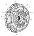
- FIG. 1 is a perspective view of a double clutch assembly according to the present invention.
- FIG. 2 is a perspective view illustrating a rear portion of the double clutch assembly illustrated in FIG. 1.
- FIG. 3 is an exploded perspective view showing the overall configuration of the double clutch assembly shown in Figs. 1 and 2, respectively.
- FIG. 4 is a cross-sectional view showing the overall configuration of the double clutch assembly shown in Figs. 1 and 2, respectively.
- FIG. 5 is a perspective view illustrating a state in which a diaphragm spring is supported by a position control structure in a state in which the cover casing is removed from FIG. 2.
- FIG. 6 is a perspective view illustrating a state in which the positioning structure is assembled with respect to the auxiliary cover casing after removing the diaphragm spring from FIG. 5.
- FIG. 7 is a perspective view showing the position control structure shown in FIG. 6.
- FIG. 8 is a perspective view of the structure for removing the position control in FIG.
- FIG. 9 is a perspective view illustrating a state in which the auxiliary diaphragm spring is supported by the auxiliary structure for positioning after removing the auxiliary cover casing from FIG. 8.
- the double clutch assembly includes a connection casing 100, a cover casing 120, an auxiliary cover casing 130, a center plate 140, a pressure plate 160, and an auxiliary pressure plate. 170, the disk assembly 180, the auxiliary disk assembly 190, the diaphragm spring 200, the auxiliary diaphragm spring 210, the positioning structure 220, and the positioning regulation structure 230. It is configured to include.
- the connecting casing 100 is configured to be directly connected to the output side of the engine to receive the driving force generated from the engine.
- the connecting casing 100 is formed of a ring-shaped disk member, and uniformly forms the serration portion 102 as a joint portion for power transmission with the engine over the entire circumference of the inner circumferential surface of the central portion.
- the connection casing 100 forms a flange portion 104 for coupling with the center plate 140 at the edge portion.
- the cover casing 120 is configured to engage with the connecting casing 100 to rotate about the central axis of the clutch when the engine is running.
- the cover casing 120 is formed of a ring-shaped disk member having a mounting hole 122 formed in the center portion so as to be disposed coaxially with the input shaft of the transmission.
- the cover casing 120 forms a flange portion 124 for coupling with the pressure plate 160 at one side edge portion.
- the auxiliary cover casing 130 is coupled to the center plate 140 and configured to rotate about the central axis of the clutch when the engine is running.
- the auxiliary cover casing 130 is formed of a ring-shaped disk member having an installation hole 132 perforated in the center portion so as to be disposed coaxially with the input shaft of the transmission.
- the auxiliary cover casing 130 forms a flange portion 134 for coupling with the center plate 140 at one side edge portion.
- the auxiliary cover casing 130 forms a rear protrusion 136 protruding toward the auxiliary diaphragm spring 210 to set a support point for the auxiliary diaphragm spring 210.
- the auxiliary cover casing 130 is provided with a plurality of first through holes 138 in the radially inner edge portion of the divided protrusion 135 for the fixed installation of the position control structure 220 by riveting. do.
- the auxiliary cover casing 130 is provided with a plurality of second through holes 139 in the edge portion to support the free end of the positioning structure auxiliary structure 230.
- the first through hole 138 and the second through hole 139 are configured to be alternately positioned as a radial arrangement structure with respect to the center of the cover casing 120.
- the center plate 140 is coupled to the cover casing 120 and configured to be idling with respect to the input shaft of the transmission located at the center of the clutch when the engine is operating.
- the center plate 140 is formed of a ring-shaped disk member having an installation hole 142 formed in the center portion so as to be disposed coaxially with the input shaft of the transmission.
- the center plate 140 forms a flange portion 144 for coupling with the connection casing 100 at a position corresponding to the flange portion 104 of the connection casing 100 at the edge portion.
- the center plate 140 installs a bearing 146 on the inner circumferential surface of the installation hole 142 for idling support for the input shaft of the transmission.
- the pressure plate 160 is coupled to the cover casing 120 and configured to rotate about the central axis of the clutch when the engine is running.
- the pressure plate 160 is formed of a ring-shaped disk member having an installation hole 162 formed in the center portion so as to be disposed outwardly coaxially with the input shaft of the transmission.
- the pressure plate 160 forms a flange portion 164 for coupling with the cover casing 120 at a position corresponding to the flange portion 124 of the cover casing 120 at the edge portion.
- the auxiliary pressure plate 170 is coupled to the center plate 140 and configured to be idling with respect to the input shaft of the transmission located at the center of the clutch when the engine is operating.
- the auxiliary pressure plate 170 is formed of a ring-shaped disc member having an installation hole 172 formed in the center portion so as to be disposed outwardly coaxially with the input shaft of the transmission.
- the auxiliary pressure plate 170 forms a flange portion 174 for coupling with the center plate 140 at the edge portion.
- the auxiliary pressure plate 170 forms a plurality of assembly holes 176 in the edge portion for the fixed installation of the positioning structure auxiliary structure 230.
- the assembly hole 176 is configured to be positioned in a radial arrangement structure with respect to the center of the auxiliary pressure plate 170 by inserting and supporting one end of the position regulating auxiliary structure 230.
- the disk assembly 180 is installed between the center plate 140 and the pressure plate 160, and has a hub 182 on the center portion for coupling with any one of the input shafts of the transmission, for example, the solid input shaft.
- the disk assembly 180 has a damper spring 184 for buffering a sudden change in driving force on the circumference of the hub 182, and facing facing between the center plate 140 and the pressure plate 160 186.
- the pressure plate 160 is pressed by the axial movement of the cover casing 120 and the connecting casing 100 when the diaphragm spring 200 contracts, and the pacing 186 is caused by the pressure of the pressure plate 160.
- the engine driving force is the hub 182 of the disk assembly 180 via the facing 186 in intimate contact between the center plate 140 and the pressure plate 160. Is transmitted to and the input shaft of the transmission can be rotated.
- the auxiliary disk assembly 190 is installed between the center plate 140 and the auxiliary pressure plate 170, and has a hub 192 for coupling with one of the input shafts of the transmission, for example, a hollow input shaft, on the center portion.
- the secondary disk assembly 190 also has a facing 194 in contact with the center plate 140 and the secondary pressure plate 170 at the periphery thereof.
- the auxiliary pressure plate 170 is pressed by the axial movement of the auxiliary cover casing 130, and the facing 194 is pressed by the auxiliary pressure plate 170.
- the engine driving force is the hub 192 of the auxiliary disk assembly 190 via the facing 194 in intimate contact between the center plate 140 and the auxiliary pressure plate 170. Is transmitted to and the input shaft of the transmission can be rotated.
- the diaphragm spring 200 is a washer-shaped leaf spring installed between the cover casing 120 and the auxiliary cover casing 130 so as to form the cut groove 202 radially from the circumferential surface of the edge portion toward the center portion. It consists of a structure having a plurality of elastic pieces divided. In this case, the center of the diaphragm spring 200 is formed in an open form for installation of the transmission input shaft.
- the diaphragm spring 200 is contracted and deformed inclined in the axial direction of the clutch according to the operation of the actuator to implement the axial displacement with respect to the cover casing 120, the center plate 140, the disk assembly 180 and the pressure plate. It is possible to transmit the engine driving force according to the connection between the 160.
- the cover casing 120 has a protrusion 126 protruding toward the diaphragm spring 200 to form a support point of the diaphragm spring 200, as shown in FIG. 4, and the auxiliary cover casing 130.
- a protrusion 126 protruding toward the diaphragm spring 200 to form a support point of the diaphragm spring 200 together with the protrusion 126 of the cover casing 120.
- the protrusion 126 is formed at an edge portion closer to the circumferential surface of the divided protrusion 136 based on the radial direction of the diaphragm spring 200.
- the auxiliary diaphragm spring 210 is a washer-shaped leaf spring installed between the auxiliary cover casing 130 and the auxiliary pressure plate 170, and forms the incision groove 212 radially from the circumferential surface of the edge portion toward the center. It is made of a structure having an elastic piece divided into a plurality. In this case, the center of the auxiliary diaphragm spring 210 is formed in an open shape for installation of the transmission input shaft.
- the auxiliary diaphragm spring 210 is also contracted and deformed in the axial direction of the clutch in accordance with the operation of the actuator in the same way as the diaphragm spring 200 to implement the axial displacement with respect to the cover casing 120, the center plate 140 ) And the transmission of the driving force according to the connection between the auxiliary disk assembly 190 and the auxiliary pressure plate 170.
- the auxiliary cover casing 130 has a back protrusion 136 protruding toward the auxiliary diaphragm spring 210 to form a support point of the auxiliary diaphragm spring 210 as shown in FIG. 4.
- the back protrusion 136 forms a support point for the auxiliary diaphragm spring 210 at a single point, unlike the protrusion 126 and the divided protrusion 137, and more specifically, the auxiliary diaphragm spring ( A support point is formed with respect to the radially outer edge of 210.
- Position control structure 220 is fixed to the auxiliary cover casing 130 to perform the function of constraining the flow in the radial and rotational direction of the diaphragm spring 200 at the same time.
- the structure for regulating position 220 includes a body 221, a mounting part 222, a first protrusion 223, and a second protrusion 224, as shown in FIG. 7.
- the body portion 221 is formed of a plate-like member which is disposed circumferentially in the space between the auxiliary cover casing 130 and the diaphragm spring 200 and fixed to the auxiliary cover casing 130.
- the mounting portion 222 extends circumferentially from the body portion 221 and is configured to have a through hole 222a for coupling with the auxiliary cover casing 130.
- the mounting portion 222 may be provided at both ends of the body portion 221, respectively.
- the first protrusion 223 protrudes in the axial direction from the body portion 221 toward the cutout groove 202 of the diaphragm spring 200 and is inserted into the cutout groove 202 so that the diaphragm spring 200 can be inserted into the cutout groove 202. It acts to constrain the radial flow.
- the first protrusion 223 is bent to protrude in the axial direction from the central portion of the body portion 221 and the free end extends horizontally so that the radially outermost inner peripheral surface of the incision groove 202 of the diaphragm spring 200 ( And 204 in surface contact.
- the first protrusion 223 is in the axial direction and the radial direction, respectively, for the surface contact for the expansion of the contact area with the radially outermost inner peripheral surface 204 of the cutting groove 202 of the diaphragm spring 200 It consists of an expanded planar structure.
- the second protrusion 224 is located radially inward from the first protrusion 223 and protrudes in the axial direction from the body portion 221 toward the cut groove 202 of the diaphragm spring 200 to cut the cut groove 202.
- the second protrusion 224 may protrude radially outwardly from both ends of the first bent portion 224a and the first bent portion 224a, which are bent to protrude in the axial direction from the central portion of the body portion 221.
- the second bent portion 224b is bent to be in surface contact with both circumferentially opposite inner peripheral surfaces 206 of the cutting groove 202 of the diaphragm spring 200, respectively. That is, the second bent portion 224b is axially and radially for surface contact for expanding the contact area with the circumferentially opposite inner circumferential surfaces 206 of the cutting groove 202 of the diaphragm spring 200, respectively. It consists of a planar structure extending each.
- the positioning structure 220 may be more preferably configured to be spaced apart from each other as a radial arrangement structure with respect to the center of the auxiliary cover casing 130.
- the shape of the first protrusion 223 and the second protrusion 224 may be embodied in various embodiments, and the second protrusion 224 may include the first protrusion ( 223 is located radially inward, but is not limited thereto.
- Positioning auxiliary structure 230 is fixed to the auxiliary pressure plate 170 to perform the function of constraining the flow in the radial and rotational direction of the auxiliary diaphragm spring 210 at the same time.
- the positioning structure auxiliary structure 230 is supported at one end by being inserted into the assembly hole 176 of the auxiliary pressure plate 170 and the other end of the auxiliary diaphragm.
- the radially outermost inner circumferential surface 214 of the cutout groove 212 of the spring 210 is configured to simultaneously face-contact with both circumferential opposite inner circumferential surfaces 216.
- the positioning structure auxiliary structure 230 may be any structure having a predetermined length in various forms, such as a pin-shaped cylindrical structure, or a structure having a square cross section.
- the positioning structure 220 has a mounting portion 222 of the body portion 221 is riveted to the first through-hole 138 of the auxiliary cover casing 130 is firmly fixed to the first protrusion 223
- the surface contact with the radially outermost inner circumferential surface 204 of the incision groove 202 of the diaphragm spring 200 can effectively suppress the radial flow of the diaphragm spring 200, the second protrusion 224
- the surface contact with the circumferentially opposite inner circumferential surfaces 206 of the cutting groove 202 of the diaphragm spring 200 can effectively suppress the rotational flow of the diaphragm spring 200.
- the first protrusion 223 of the position regulating structure 220 is in surface contact with the radially outermost inner circumferential surface 204 of the cutout groove 202 of the diaphragm spring 200, and the second protrusion 224.
- the diaphragm spring for the secondary cover casing 130 through the area expansion for the contact portion, respectively, as the surface contact with each of the circumferential both sides of the inner peripheral surface 206 of the incision groove 202 of the diaphragm spring 200
- the condensation of the diaphragm spring 200 with respect to the center of each hub 182 and 192 can be maintained in an exact position while effectively constraining the flow in the radial and rotational directions of the 200 at the same time.
- Prevent eccentric contact between the disc assembly 180 and the disc assembly 180 induce uniform load transfer between the pressure plate 160 and the disc assembly 180 when the clutch is engaged, and improve the geometric judder, When extending the life greatly It can be so.
- the positioning structure auxiliary structure 230 is one end is inserted into and supported by the assembly hole 176 of the auxiliary pressure plate 170, the radially outermost inner peripheral surface 214 of the auxiliary diaphragm spring 210 and the circumferentially opposite inner peripheral surface
- the other end side free end is inserted into and supported by the second through hole 139 of the auxiliary cover casing 130 while being in surface contact with each of the 216, thereby simultaneously allowing the radial and rotational directions of the auxiliary diaphragm spring 210 to flow. It can be effectively suppressed.
- auxiliary structure 230 for positioning may maintain the concentricity of the auxiliary diaphragm spring 210 in the same position as the positioning structure 220, the auxiliary pressure plate 170 and the auxiliary disk assembly ( It is possible to prevent eccentric contact occurring between the 190 and induce uniform load transfer between the auxiliary pressure plate 170 and the auxiliary disk assembly 190 when the clutch is engaged.
Abstract
본 발명은 보조 커버 케이싱에 대해 다이아프램 스프링의 반경방향과 회전방향의 유동을 동시에 구속하면서 다이아프램 스프링과의 회전방향 접촉면적을 확장시킴으로써 허브 중심에 대한 다이아프램 스프링의 동심도를 정위치로 정렬하고 유지할 수 있게 하고 압력판과 디스크 조립체 사이의 편심 접촉에 따라 발생하는 디스크 조립체의 편마모를 방지할 수 있는 더블 클러치 조립체를 개시한다. 본 발명의 더블 클러치 조립체는 보조 커버 케이싱(130)과 다이아프램 스프링(200) 사이의 공간에 배치되면서 보조 커버 케이싱(130)에 고정되는 바디부(221), 바디부(221)로부터 원주방향으로 연장되어 보조 커버 케이싱(130)에 결합되는 마운팅부(222), 바디부(221)로부터 다이아프램 스프링(200)의 절개홈(202)을 향해 축방향으로 돌출되어 절개홈(202)의 내부로 삽입되어 반경방향 유동을 구속하는 제1돌출부(223), 및 바디부(221)로부터 다이아프램 스프링(200)의 절개홈(202)을 향해 축방향으로 돌출되어 절개홈(202)의 내부로 삽입되어 회전방향 유동을 구속하는 제2돌출부(224)를 갖추고서, 보조 커버 케이싱(130)에 설치되어 다이아프램 스프링(200)의 반경방향과 회전방향의 유동을 구속하는 위치규제용 구조물(220)을 구비한다.
Description
본 발명은 더블 클러치 조립체에 관한 것으로, 더욱 상세하게는 보조 커버 케이싱에 대해 다이아프램 스프링의 반경방향과 회전방향의 유동을 동시에 구속하면서 다이아프램 스프링과의 회전방향 접촉면적을 확장시킴으로써 허브 중심에 대한 다이아프램 스프링의 동심도를 정위치로 정렬하여 유지할 수 있게 하고 압력판과 디스크 조립체 사이의 편심 접촉에 따라 발생하는 디스크의 편마모를 방지할 수 있는 더블 클러치 조립체에 관한 것이다.
일반적으로 두 개의 입력축을 가지는 더블 클러치 트랜스미션(Double Clutch T/M)은 엔진으로부터의 동력을 전달하기 위해서 클러치 디스크가 두 개인 더블 클러치의 사용이 요구된다. 이러한 더블 클러치는 클러치가 두 개가 필요하고, 기어방식도 듀얼(Dual)로 작동되며 한 개 단씩 변속될 때마다 이중으로 되어 있는 샤프트가 바뀌기 때문에 변속 속도가 빠르며 실제 연비에도 도움이 된다.
특히, 건식 더블 클러치(Dry Double Clutch)는 종래의 습식 더블 클러치(Wet Double Clutch)와는 다르게 오일을 사용하지 않고, 클러치 디스크와 압력판의 마찰에 의해서 엔진의 동력을 트랜스미션에 전달하게 된다. 이러한 건식 더블 클러치는 등록특허 제10-1180599호에 개시되어 있다.
종래, 더블 클러치(1)는 댐퍼 플라이휠(3)과 셋 더블 클러치(5)를 포함하는 구성으로, 셋 더블 클러치(5)의 환형 케이싱(13)에 의해 외주연이 묻히고 외주연을 제외한 부분은 상기 환형 케이싱(13) 밖으로 노출되도록 동축 상으로 고정된 제1 다이어프램 스프링(7), 제1 다이어프램 스프링(7) 안쪽에 동축 상으로 인접 배치되어 외주연에서 바깥쪽 방향으로 돌출된 동축 상의 엠보싱부(15)에 의해 상기 제1 다이어프램 스프링(7)의 외주연을 지지하는 커버판(9), 커버판(9)의 안쪽에 동축 상으로 인접 배치되어 셋 더블 클러치(5)의 제1 압력판(21)을 가압하도록 되어 있는 제2 다이어프램 스프링(11), 및 커버판(9)의 외주연과 제2 다이어프램 스프링(11)의 외주연 사이에 동축 상으로 개재되어 커버판(9)에 의해 제2 다이어프램 스프링(11)이 지지되도록 하는 환형의 지지부재(10)를 포함한다.
그러나 종래 더블 클러치는 다이아프램 스프링의 수축과 복원시 클러치와 다이아프램 스프링 사이의 축 중심이 틀어지는 문제를 유발하게 되고, 이러한 동심도의 불일치는 압력판과 디스크 사이의 편심 접촉을 초래하여 디스크의 편마모를 수반하는 문제를 초래하게 된다.
본 발명이 해결하고자 하는 기술적 과제는 보조 커버 케이싱에 대해 다이아프램 스프링의 반경방향과 회전방향의 유동을 동시에 구속하면서 다이아프램 스프링과의 회전방향 접촉면적을 확장시킴으로써 허브 중심에 대한 다이아프램 스프링의 동심도를 정위치로 정렬하고 유지할 수 있게 하고 압력판과 디스크 조립체 사이의 편심 접촉에 따라 발생하는 디스크 조립체의 편마모를 방지할 수 있는 더블 클러치 조립체를 제공하는 것이다.
상기와 같은 목적을 달성하기 위한 본 발명은 엔진으로부터 구동력을 제공받아 회전하도록 설치되는 커버 케이싱, 상기 커버 케이싱에 대해 축방향으로 수축 가능하게 설치되는 다이아프램 스프링, 상기 커버 케이싱과 결합되고 변속기의 입력축에 대해 공회전 가능하게 설치되는 센터 플레이트, 상기 센터 플레이트와 결합되고 상기 커버 케이싱과 함께 다이아프램 스프링의 지지점을 형성하는 보조 커버 케이싱, 상기 커버 케이싱과 결합되고 변속기의 입력축에 대해 공회전 가능하게 설치되는 압력판, 상기 센터 플레이트와 결합되고 변속기의 입력축에 대해 공회전 가능하게 설치되는 보조 압력판, 상기 보조 커버 케이싱과 상기 보조 압력판 사이에 설치되는 보조 다이아프램 스프링, 상기 센터 플레이트와 상기 압력판 사이에 설치되고 변속기의 입력축과 결합되는 허브를 갖추고서 상기 압력판을 통해 전달되는 구동력을 변속기의 입력축으로 제공하는 디스크 조립체, 상기 센터 플레이트와 상기 보조 압력판 사이에 설치되고 변속기의 입력축과 결합되는 허브를 갖추고서 상기 보조 압력판을 통해 전달되는 구동력을 변속기의 입력축으로 제공하는 보조 디스크 조립체, 및 상기 보조 커버 케이싱에 고정되어 상기 다이아프램 스프링의 반경방향과 회전방향의 유동을 구속하는 위치규제용 구조물을 구비하고, 상기 위치규제용 구조물은 상기 보조 커버 케이싱과 상기 다이아프램 스프링 사이의 공간에 배치되면서 상기 보조 커버 케이싱에 고정되는 바디부, 상기 바디부로부터 원주방향으로 연장되어 상기 보조 커버 케이싱에 결합되는 마운팅부, 상기 바디부로부터 상기 다이아프램 스프링의 절개홈을 향해 축방향으로 돌출되어 상기 절개홈의 내부로 삽입되어 반경방향 유동을 구속하는 제1돌출부, 및 상기 바디부로부터 상기 다이아프램 스프링의 절개홈을 향해 축방향으로 돌출되어 상기 절개홈의 내부로 삽입되어 회전방향 유동을 구속하는 제2돌출부를 포함하도록 구성되는 것이 바람직하다.
본 발명에 있어, 상기 마운팅부는 상기 바디부의 양단부에 형성되고, 상기 보조 커버 케이싱과의 결합을 위한 관통구멍을 구비하는 것이 바람직하다.
본 발명에 있어, 상기 제1돌출부는 상기 바디부의 중앙부위에서 축방향으로 돌출되도록 절곡되면서 자유단부가 수평하게 연장되어 상기 다이아프램 스프링의 절개홈의 반경방향 최외곽 내주면과 면접촉하도록 구성되는 것이 바람직하다.
본 발명에 있어, 상기 제2돌출부는 상기 제1돌출부로부터 반경방향 내측에 위치하는 것이 바람직하다.
본 발명에 있어, 상기 제2돌출부는 상기 바디부의 중앙부위에서 축방향으로 돌출되도록 절곡되는 제1절곡부, 및 상기 제1절곡부의 양단부에서 반경방향 외측으로 돌출되도록 절곡되어 상기 다이아프램 스프링의 절개홈의 원주방향 양측 내주면과 각각 면접촉하는 제2절곡부를 구비하는 것이 바람직하다.
본 발명에 있어, 상기 위치규제용 구조물은 상기 보조 커버 케이싱의 중심에 대해 방사상 배치 구조로 설치되고, 상기 보조 커버 케이싱은 상기 마운팅부와의 체결을 위한 제1관통구멍을 구비하는 것이 바람직하다.
본 발명은 상기 보조 압력판에 고정되어 상기 보조 다이아프램 스프링의 반경방향과 회전방향의 유동을 구속하는 위치규제용 보조 구조물을 더 포함하고, 상기 위치규제용 보조 구조물은 일단부가 상기 보조 압력판의 조립구멍에 삽입되어 지지되고 타단부가 상기 보조 다이아프램 스프링의 절개홈의 반경방향 최외곽 내주면과 원주방향 양측 내주면에 면접촉하도록 구성되는 것이 바람직하다.
본 발명에 있어, 상기 위치규제용 보조 구조물은 상기 보조 압력판의 중심에 대해 방사상 배치 구조로 설치되고, 상기 보조 커버 케이싱은 상기 위치규제용 보조 구조물의 삽입을 위한 제2관통구멍을 구비하는 것이 바람직하다.
본 발명의 실시예에 따른 더블 클러치 조립체는 보조 커버 케이싱에 설치되어 다이아프램 스프링의 반경방향과 회전방향의 유동을 동시에 구속할 수 있으므로, 클러치의 작동에 따른 다이아프램 스프링의 압축과 복원시 클러치의 허브 중심에 대한 다이아프램 스프링의 동심도를 정상의 상태로 정렬하고 유지할 수 있게 할 수 있게 된다.
또한, 본 발명은 클러치의 허브 중심에 대한 다이아프램 스프링의 동심도를 정위치로 정렬하여 유지할 수 있고, 압력판과 디스크 조립체 사이의 편심 접촉을 방지하여 클러치의 체결시 압력판과 디스크 조립체 사이에서 균일한 하중 전달을 유도함으로써 지오메트릭 저더를 개선할 수 있게 된다.
특히, 본 발명은 다이아프램 스프링의 절개홈과 위치규제용 구조물 사이의 반경방향과 회전방향으로의 접촉을 각각 면접촉의 방식을 통해 접촉부위의 면적을 확장시킬 수 있으므로, 외력에 의한 편심 발생시 회전방향으로의 접촉면적 확장에 따른 편마모의 개선을 통해 제품의 수명이 단축되는 것이 적극적으로 예방할 수 있게 된다.
도 1은 본 발명에 따른 더블 클러치 조립체를 도시한 사시도이다.
도 2는 도 1에 도시된 더블 클러치 조립체의 배면부위를 도시한 사시도이다.
도 3은 도 1과 도 2에 각각 도시된 더블 클러치 조립체의 전체 구성을 도시한 분해 사시도이다.
도 4는 도 1과 도 2에 각각 도시된 더블 클러치 조립체의 전체 구성을 도시한 단면도이다.
도 5는 도 2에서 커버 케이싱을 제거한 상태에서 위치규제용 구조물에 의해 다이아프램 스프링이 지지된 상태를 도시한 사시도이다.
도 6은 도 5에서 다이아프램 스프링을 제거한 다음, 위치규제용 구조물이 보조 커버 케이싱에 대해 조립된 상태를 도시한 사시도이다.
도 7은 도 6에 도시된 위치규제용 구조물을 도시한 사시도이다.
도 8은 도 6에서 위치규제용 구조물을 제거하여 도시한 사시도이다.
도 9는 도 8에서 보조 커버 케이싱을 제거한 다음, 위치규제용 보조 구조물에 의해 보조 다이아프램 스프링이 지지된 상태를 도시한 사시도이다.
이하, 본 발명의 실시예를 첨부된 예시도면을 참조로 하여 상세히 설명한다.
도 1 내지 도 4를 참조로 하면, 본 발명에 따른 더블 클러치 조립체는 접속 케이싱(100), 커버 케이싱(120), 보조 커버 케이싱(130), 센터 플레이트(140), 압력판(160), 보조 압력판(170), 디스크 조립체(180), 보조 디스크 조립체(190), 다이아프램 스프링(200), 보조 다이아프램 스프링(210), 위치규제용 구조물(220), 및 위치규제용 보조 구조물(230)을 포함하여 구성된다.
접속 케이싱(100)은 엔진의 출력측과 직접적으로 연결되어 엔진으로부터 발생되는 구동력을 제공받도록 구성된다. 이를 위해 접속 케이싱(100)은 링 형상의 원판부재로 형성되고, 중앙부위의 내주면 전 둘레에 걸쳐 엔진과의 동력 전달을 위한 이음부위로서 세레이션부(102)를 동심원상으로 균일하게 형성한다. 또한, 접속 케이싱(100)은 가장자리 부위에 센터 플레이트(140)와의 결합을 위한 플랜지부(104)를 형성한다.
커버 케이싱(120)은 접속 케이싱(100)과 결합되어 엔진의 가동시 클러치의 중심축에 대해 회전하도록 구성된다. 이를 위해 커버 케이싱(120)은 변속기의 입력축과 동축상으로 외측에 배치되도록 중앙부위에 천공된 형태의 설치구멍(122)을 갖춘 링 형상의 원판부재로 형성된다. 또한, 커버 케이싱(120)은 일측 가장자리 부위에 압력판(160)과의 결합을 위한 플랜지부(124)를 형성한다.
보조 커버 케이싱(130)은 센터 플레이트(140)와 결합되어 엔진의 가동시 클러치의 중심축에 대해 회전하도록 구성된다. 이를 위해 보조 커버 케이싱(130)은 변속기의 입력축과 동축상으로 외측에 배치되도록 중앙부위에 천공된 형태의 설치구멍(132)을 갖춘 링 형상의 원판부재로 형성된다. 또한, 보조 커버 케이싱(130)은 일측 가장자리 부위에 센터 플레이트(140)와의 결합을 위한 플랜지부(134)를 형성한다. 또한, 보조 커버 케이싱(130)은 보조 다이아프램 스프링(210)에 대한 지지점의 설정을 위해 보조 다이아프램 스프링(210)을 향해 돌출되는 배면돌기부(136)를 형성한다.
또한, 보조 커버 케이싱(130)은 리벳팅에 의한 위치규제용 구조물(220)의 고정 설치를 위해 분할형 돌기부(135)의 반경방향 내측의 가장자리 부위에 다수의 제1관통구멍(138)을 구비한다. 또한, 보조 커버 케이싱(130)은 위치규제용 보조 구조물(230)의 자유단부에 대한 지지를 위해 가장자리 부위에 다수의 제2관통구멍(139)을 구비한다. 이 경우, 제1관통구멍(138)과 제2관통구멍(139)은 커버 케이싱(120)의 중심에 대해 방사상의 배치 구조로서 상호 교호적으로 위치하도록 구성된다.
센터 플레이트(140)는 커버 케이싱(120)과 결합되어 엔진의 가동시 클러치의 중심에 위치하는 변속기의 입력축에 대해 공회전 가능하도록 구성된다. 이를 위해, 센터 플레이트(140)는 변속기의 입력축과 동축상으로 외측에 배치되도록 중앙부위에 천공된 형태의 설치구멍(142)을 갖춘 링 형상의 원판부재로 형성된다. 또한, 센터 플레이트(140)는 가장자리 부위에 접속 케이싱(100)의 플랜지부(104)와 대응하는 위치에 접속 케이싱(100)과의 결합을 위한 플랜지부(144)를 형성한다. 또한, 센터 플레이트(140)는 설치구멍(142)의 내주면에 변속기의 입력축에 대한 공회전 가능한 지지를 위해 베어링(146)을 설치한다.
압력판(160)은 커버 케이싱(120)과 결합되어 엔진의 가동시 클러치의 중심축에 대해 회전하도록 구성된다. 이를 위해, 압력판(160)은 변속기의 입력축과 동축상으로 외측에 배치되도록 중앙부위에 천공된 형태의 설치구멍(162)을 갖춘 링 형상의 원판부재로 형성된다. 또한, 압력판(160)은 가장자리 부위에 커버 케이싱(120)의 플랜지부(124)와 대응하는 위치에 커버 케이싱(120)과의 결합을 위한 플랜지부(164)를 형성한다.
보조 압력판(170)은 센터 플레이트(140)와 결합되어 엔진의 가동시 클러치의 중심에 위치하는 변속기의 입력축에 대해 공회전 가능하도록 구성된다. 이를 위해, 보조 압력판(170)은 변속기의 입력축과 동축상으로 외측에 배치되도록 중앙부위에 천공된 형태의 설치구멍(172)을 갖춘 링 형상의 원판부재로 형성된다. 또한, 보조 압력판(170)은 가장자리 부위에 센터 플레이트(140)와의 결합을 위한 플랜지부(174)를 형성한다.
또한, 보조 압력판(170)은 위치규제용 보조 구조물(230)의 고정 설치를 위해 가장자리 부위에 다수의 조립구멍(176)을 형성한다. 이 경우, 조립구멍(176)은 위치규제용 보조 구조물(230)의 일단부를 삽입시켜 지지하는 것으로 보조 압력판(170)의 중심에 대해 방사상의 배치 구조로 위치하도록 구성된다.
디스크 조립체(180)는 센터 플레이트(140)와 압력판(160) 사이에 설치되는 것으로, 중심부위에 변속기의 입력축 중 어느 하나, 예컨대 중실의 입력축과의 결합을 위해 허브(182)를 구비한다. 또한, 디스크 조립체(180)는 허브(182)의 둘레부위에 급격한 구동력의 변화를 완충시키기 위한 댐퍼 스프링(184)을 구비하고, 센터 플레이트(140)와 압력판(160) 사이에서 이들과 접촉 가능한 페이싱(186)을 구비한다.
이에 따라, 다이아프램 스프링(200)의 수축시 커버 케이싱(120)과 접속 케이싱(100)의 축방향 이동에 의해 압력판(160)의 가압이 이루어지고, 압력판(160)의 가압에 의해 페이싱(186)은 센터 플레이트(140)와 접촉하게 되며, 이를 통해 엔진 구동력은 센터 플레이트(140)와 압력판(160) 사이에서 긴밀하게 접촉하는 페이싱(186)을 매개로 디스크 조립체(180)의 허브(182)로 전달되어 변속기의 입력축을 회전시킬 수 있게 된다.
보조 디스크 조립체(190)는 센터 플레이트(140)와 보조 압력판(170) 사이에 설치되는 것으로, 중심부위에 변속기의 입력축 중 어느 하나, 예컨대 중공의 입력축과의 결합을 위한 허브(192)를 구비한다. 또한, 보조 디스크 조립체(190)는 둘레부위에 센터 플레이트(140)와 보조 압력판(170) 사이에서 이들과 접촉 가능한 페이싱(194)을 구비한다.
이에 따라, 보조 다이아프램 스프링(210)의 수축시 보조 커버 케이싱(130)의 축방향 이동에 의해 보조 압력판(170)의 가압이 이루어지고, 보조 압력판(170)의 가압에 의해 페이싱(194)은 센터 플레이트(140)와 접촉하게 되며, 이를 통해 엔진 구동력은 센터 플레이트(140)와 보조 압력판(170) 사이에서 긴밀하게 접촉하는 페이싱(194)을 매개로 보조 디스크 조립체(190)의 허브(192)로 전달되어 변속기의 입력축을 회전시킬 수 있게 된다.
다이아프램 스프링(200)은 커버 케이싱(120)과 보조 커버 케이싱(130) 사이에 설치되는 와셔 형태의 판스프링으로, 가장자리 부위의 원주면으로부터 중심부위를 향해 방사상으로 절개홈(202)을 형성하도록 다수로 분할된 탄성편을 갖춘 구조로 이루어진다. 이 경우, 다이아프램 스프링(200)의 중심부위는 변속기 입력축의 설치를 위해 개구된 형태로 형성된다.
또한, 다이아프램 스프링(200)은 액츄에이터의 작동에 따라 클러치의 축방향으로 경사지게 수축 변형되어 커버 케이싱(120)에 대한 축방향 변위를 구현함으로써 센터 플레이트(140)와 디스크 조립체(180) 및 압력 플레이트(160) 사이의 접속에 따른 엔진 구동력의 전달을 도모하게 된다.
이를 위해, 커버 케이싱(120)은 도 4에 도시된 바와 같이 다이아프램 스프링(200)의 지지점 형성을 위해 다이아프램 스프링(200)을 향해 돌출된 돌기부(126)를 구비하고, 보조 커버 케이싱(130)은 커버 케이싱(120)의 돌기부(126)와 함께 다이아프램 스프링(200)의 지지점을 형성하도록 다이아프램 스프링(200)을 향해 돌출된 분할형 돌기부(137)를 구비한다. 이때, 돌기부(126)는 다이아프램 스프링(200)의 반경방향을 기준으로 분할형 돌기부(136) 보다 원주면에 인접한 가장자리 부위에 형성된다.
보조 다이아프램 스프링(210)은 보조 커버 케이싱(130)과 보조 압력판(170) 사이에 설치되는 와셔 형태의 판스프링으로, 가장자리 부위의 원주면으로부터 중심부위를 향해 방사상으로 절개홈(212)을 형성하도록 다수로 분할된 탄성편을 갖춘 구조로 이루어진다. 이 경우, 보조 다이아프램 스프링(210)의 중심부위는 변속기 입력축의 설치를 위해 개구된 형태로 형성된다. 또한, 보조 다이아프램 스프링(210)도 다이아프램 스프링(200)과 동일하게 액츄에이터의 작동에 따라 클러치의 축방향으로 경사지게 수축 변형되어 커버 케이싱(120)에 대한 축방향 변위를 구현함으로써 센터 플레이트(140)와 보조 디스크 조립체(190) 및 보조 압력판(170) 사이의 접속에 따른 구동력의 전달을 도모하게 된다. 이를 위해, 보조 커버 케이싱(130)은 도 4에 도시된 바와 같이 보조 다이아프램 스프링(210)의 지지점 형성을 위해 보조 다이아프램 스프링(210)을 향해 돌출된 배면돌기부(136)를 구비한다. 이 경우, 배면돌기부(136)는 돌기부(126) 및 분할형 돌기부(137)와 달리 단일의 개소에서 보조 다이아프램 스프링(210)에 대한 지지점을 형성하게 되고, 더욱 상세하게는 보조 다이아프램 스프링(210)의 반경방향 외측 가장자리부위에 대해 지지점을 형성하는 위치로 마련된다.
위치규제용 구조물(220)은 보조 커버 케이싱(130)에 고정되게 설치되어 다이아프램 스프링(200)의 반경방향과 회전방향의 유동을 동시에 구속하는 기능을 수행한다. 이를 위해 위치규제용 구조물(220)은 도 7에 도시된 바와 같이, 바디부(221)와 마운팅부(222), 제1돌출부(223), 및 제2돌출부(224)를 포함하여 구성된다.
바디부(221)는 보조 커버 케이싱(130)과 다이아프램 스프링(200) 사이의 공간에서 원주방향으로 배치되어 보조 커버 케이싱(130)에 대해 고정되는 평판형태의 부재로 이루어진다.
마운팅부(222)는 바디부(221)로부터 원주방향으로 길게 연장되어 보조 커버 케이싱(130)과의 결합을 위한 관통구멍(222a)을 갖추도록 구성된다. 이 경우, 마운팅부(222)는 바디부(221)의 양단부에 각각 구비되는 것이 바람직할 것이다.
제1돌출부(223)는 바디부(221)로부터 다이아프램 스프링(200)의 절개홈(202)을 향해 축방향으로 돌출되어 절개홈(202)의 내부로 삽입됨으로써 다이아프램 스프링(200)에 대한 반경방향 유동을 구속하는 역할을 수행한다. 특히, 제1돌출부(223)는 바디부(221)의 중앙부위에서 축방향으로 돌출되도록 절곡되면서 자유단부가 수평하게 연장되어 다이아프램 스프링(200)의 절개홈(202)의 반경방향 최외곽 내주면(204)과 면접촉하도록 구성된다. 즉, 상기 제1돌출부(223)는 상기 다이아프램 스프링(200)의 절개홈(202)의 반경방향 최외곽 내주면(204)과 접촉면적의 확장을 위한 면접촉을 위해 축방향과 반경방향으로 각각 확장되는 면상구조로 이루어진다.
제2돌출부(224)는 제1돌출부(223)로부터 반경방향 내측에 위치하고, 바디부(221)로부터 다이아프램 스프링(200)의 절개홈(202)을 향해 축방향으로 돌출되어 절개홈(202)의 내부로 삽입됨으로써 다이아프램 스프링(200)에 대한 회전방향 유동을 구속하는 역할을 수행한다. 특히, 제2돌출부(224)는 상기 바디부(221)의 중앙부위에서 축방향으로 돌출되도록 절곡되는 제1절곡부(224a), 및 제1절곡부(224a)의 양단부에서 반경방향 외측으로 돌출되도록 절곡되어 다이아프램 스프링(200)의 절개홈(202)의 원주방향 양측 내주면(206)과 각각 면접촉하는 제2절곡부(224b)를 갖추도록 구성된다. 즉, 상기 제2절곡부(224b)는 상기 다이아프램 스프링(200)의 절개홈(202)의 원주방향 양측 내주면(206)과 각각 접촉면적의 확장을 위한 면접촉을 위해 축방향과 반경방향으로 각각 확장되는 면상구조로 이루어진다.
또한, 위치규제용 구조물(220)은 보조 커버 케이싱(130)의 중심에 대해 방사상의 배치 구조로서 상호 적정의 간격을 두고 이격되게 설치되도록 구성되는 것이 더욱 바람직할 것이다. 또한, 본 발명의 실시예에 있어 제1돌출부(223)와 제2돌출부(224)의 형상은 다양한 형태의 변형 실시예로 구현될 수 있는 것이고, 특히 제2돌출부(224)는 제1돌출부(223)로부터 반경방향 내측에 위치하는 것을 예시하였으나, 이에 한정되는 것은 아니다.
위치규제용 보조 구조물(230)은 보조 압력판(170)에 고정되어 보조 다이아프램 스프링(210)의 반경방향과 회전방향의 유동을 동시에 구속하는 기능을 수행한다. 이를 위해 위치규제용 보조 구조물(230)은 도 3과 도 8 및 도 9에 도시된 바와 같이, 일단부가 상기 보조 압력판(170)의 조립구멍(176)에 삽입되어 지지되고 타단부가 보조 다이아프램 스프링(210)의 절개홈(212)의 반경방향 최외곽 내주면(214) 원주방향 양측 내주면(216)에 대해 각각 동시에 면접촉하도록 구성된다. 특히, 위치규제용 보조 구조물(230)의 타단부측 자유단부는 보조 다이아프램 스프링(210)의 절개홈(212)을 지나 보조 커버 케이싱(130)에 형성되는 제2관통구멍(139)을 통해 외부로 노출되도록 삽입 설치됨으로써 보다 견고한 설치를 구현할 수 있게 된다. 이 경우, 위치규제용 보조 구조물(230)은 핀 형태의 원기둥 형상의 구조물이나, 각형의 단면을 가지는 구조물 등 다양한 형태로서 소정의 길이를 가지는 구조물이라면 어느 것이라도 무방할 것이다.
따라서 위치규제용 구조물(220)은 바디부(221)의 마운팅부(222)가 보조 커버 케이싱(130)의 제1관통구멍(138)에 대해 리벳팅되어 견고하게 고정되면서 제1돌출부(223)가 다이아프램 스프링(200)의 절개홈(202)의 반경방향 최외곽 내주면(204)과 면접촉함으로써 다이아프램 스프링(200)의 반경방향 유동을 효과적으로 억제할 수 있고, 제2돌출부(224)가 다이아프램 스프링(200)의 절개홈(202)의 원주방향 양측 내주면(206)과 각각 면접촉함으로써 다이아프램 스프링(200)의 회전방향 유동을 효과적으로 억제할 수 있게 된다.
이 경우, 위치규제용 구조물(220)의 제1돌출부(223)는 다이아프램 스프링(200)의 절개홈(202)의 반경방향 최외곽 내주면(204)에 대해 면접촉하고, 제2돌출부(224)는 다이아프램 스프링(200)의 절개홈(202)의 원주방향 양측 내주면(206)에 대해 각각 면접촉함에 따라, 각각 접촉부위에 대한 면적 확장을 통해 보조 커버 케이싱(130)에 대한 다이아프램 스프링(200)의 반경방향과 회전방향의 유동을 동시에 효과적으로 구속함과 더불어 각 허브(182,192)의 중심에 대한 다이아프램 스프링(200)의 동심도를 정위치로 정렬한 상태에서 지속할 수 있으므로, 압력판(160)과 디스크 조립체(180) 사이에서 발생하는 편심 접촉을 예방하고, 클러치의 체결시 압력판(160)과 디스크 조립체(180) 사이에서 균일한 하중 전달을 유도하여 지오메트릭 저더를 개선하고, 제품의 수명을 크게 연장시킬 수 있게 된다.
또한, 위치규제용 보조 구조물(230)은 일단부가 보조 압력판(170)의 조립구멍(176)에 삽입되어 지지되면서 보조 다이아프램 스프링(210)의 반경방향 최외곽 내주면(214)과 원주방향 양측 내주면(216)에 대해 각각 면접촉하면서 타단측 자유단부가 보조 커버 케이싱(130)의 제2관통구멍(139)에 삽입되어 지지됨으로써 보조 다이아프램 스프링(210)의 반경방향과 회전방향의 유동을 동시에 효과적으로 억제할 수 있게 된다.
이 경우에도, 위치규제용 보조 구조물(230)은 위치규제용 구조물(220)과 동일하게 보조 다이아프램 스프링(210)에 대한 동심도를 정위치로 유지할 수 있으므로 보조 압력판(170)과 보조 디스크 조립체(190) 사이에서 발생하는 편심 접촉을 예방하고, 클러치의 체결시 보조 압력판(170)과 보조 디스크 조립체(190) 사이에서 균일한 하중 전달을 유도할 수 있게 된다.
Claims (8)
- 엔진으로부터 구동력을 제공받아 회전하도록 설치되는 커버 케이싱;상기 커버 케이싱에 대해 축방향으로 수축 가능하게 설치되는 다이아프램 스프링;상기 커버 케이싱과 결합되고 변속기의 입력축에 대해 공회전 가능하게 설치되는 센터 플레이트;상기 센터 플레이트와 결합되고 상기 다이아프램 스프링의 지지점을 형성하는 보조 커버 케이싱;상기 커버 케이싱과 결합되고 변속기의 입력축에 대해 공회전 가능하게 설치되는 압력판;상기 센터 플레이트와 결합되고 변속기의 입력축에 대해 공회전 가능하게 설치되는 보조 압력판;상기 보조 커버 케이싱과 상기 보조 압력판 사이에 설치되는 보조 다이아프램 스프링;상기 센터 플레이트와 상기 압력판 사이에 설치되고 변속기의 입력축과 결합되는 허브를 갖춘 디스크 조립체;상기 센터 플레이트와 상기 보조 압력판 사이에 설치되고 변속기의 입력축과 결합되는 허브를 갖춘 보조 디스크 조립체; 및상기 보조 커버 케이싱에 고정되어 상기 다이아프램 스프링의 반경방향과 회전방향의 유동을 구속하는 위치규제용 구조물을 구비하고,상기 위치규제용 구조물은 상기 보조 커버 케이싱과 상기 다이아프램 스프링 사이의 공간에 배치되면서 상기 보조 커버 케이싱에 고정되는 바디부, 상기 바디부로부터 원주방향으로 연장되어 상기 보조 커버 케이싱에 결합되는 마운팅부, 상기 바디부로부터 상기 다이아프램 스프링의 절개홈을 향해 축방향으로 돌출되어 상기 절개홈의 내부로 삽입되어 반경방향 유동을 구속하는 제1돌출부, 및 상기 바디부로부터 상기 다이아프램 스프링의 절개홈을 향해 축방향으로 돌출되어 상기 절개홈의 내부로 삽입되어 회전방향 유동을 구속하는 제2돌출부를 포함하는 것을 특징으로 하는 더블 클러치 조립체.
- 청구항 1에 있어서,상기 마운팅부는 상기 바디부의 양단부에 형성되고, 상기 보조 커버 케이싱과의 결합을 위한 관통구멍을 구비하는 것을 특징으로 하는 더블 클러치 조립체.
- 청구항 2에 있어서,상기 제1돌출부는 상기 바디부의 중앙부위에서 축방향으로 돌출되도록 절곡되면서 자유단부가 수평하게 연장되어 상기 다이아프램 스프링의 절개홈의 반경방향 최외곽 내주면과 면접촉하도록 구성되는 것을 특징으로 하는 더블 클러치 조립체.
- 청구항 1에 있어서,상기 제2돌출부는 상기 제1돌출부로부터 반경방향 내측에 위치하는 것을 특징으로 하는 더블 클러치 조립체.
- 청구항 2에 있어서,상기 제2돌출부는 상기 바디부의 중앙부위에서 축방향으로 돌출되도록 절곡되는 제1절곡부, 및 상기 제1절곡부의 양단부에서 반경방향 외측으로 돌출되도록 절곡되어 상기 다이아프램 스프링의 절개홈의 원주방향 양측 내주면과 각각 면접촉하는 제2절곡부를 구비하는 것을 특징으로 하는 더블 클러치 조립체.
- 청구항 1에 있어서,상기 위치규제용 구조물은 상기 보조 커버 케이싱의 중심에 대해 방사상 배치 구조로 설치되고, 상기 보조 커버 케이싱은 상기 마운팅부와의 체결을 위한 제1관통구멍을 구비하는 것을 특징으로 하는 더블 클러치 조립체.
- 청구항 1에 있어서,상기 보조 압력판에 고정되어 상기 보조 다이아프램 스프링의 반경방향과 회전방향의 유동을 구속하는 위치규제용 보조 구조물을 더 포함하고, 상기 위치규제용 보조 구조물은 일단부가 상기 보조 압력판의 조립구멍에 삽입되어 지지되고 타단부가 상기 보조 다이아프램 스프링의 절개홈의 반경방향 최외곽 내주면과 원주방향 양측 내주면에 면접촉하도록 구성되는 것을 특징으로 하는 더블 클러치 조립체.
- 청구항 7에 있어서,상기 위치규제용 보조 구조물은 상기 보조 압력판의 중심에 대해 방사상 배치 구조로 설치되고, 상기 보조 커버 케이싱은 상기 위치규제용 보조 구조물의 삽입을 위한 제2관통구멍을 구비하는 것을 특징으로 하는 더블 클러치 조립체.
Priority Applications (3)
| Application Number | Priority Date | Filing Date | Title |
|---|---|---|---|
| CN201980049741.XA CN112513485B (zh) | 2018-07-27 | 2019-07-25 | 双离合器组件 |
| EP19839955.2A EP3832156A4 (en) | 2018-07-27 | 2019-07-25 | DOUBLE CLUTCH ASSEMBLY |
| US17/263,480 US11773918B2 (en) | 2018-07-27 | 2019-07-25 | Double clutch assembly |
Applications Claiming Priority (2)
| Application Number | Priority Date | Filing Date | Title |
|---|---|---|---|
| KR10-2018-0087824 | 2018-07-27 | ||
| KR1020180087824A KR102094607B1 (ko) | 2018-07-27 | 2018-07-27 | 더블 클러치 조립체 |
Publications (1)
| Publication Number | Publication Date |
|---|---|
| WO2020022813A1 true WO2020022813A1 (ko) | 2020-01-30 |
Family
ID=69182349
Family Applications (1)
| Application Number | Title | Priority Date | Filing Date |
|---|---|---|---|
| PCT/KR2019/009271 WO2020022813A1 (ko) | 2018-07-27 | 2019-07-25 | 더블 클러치 조립체 |
Country Status (5)
| Country | Link |
|---|---|
| US (1) | US11773918B2 (ko) |
| EP (1) | EP3832156A4 (ko) |
| KR (1) | KR102094607B1 (ko) |
| CN (1) | CN112513485B (ko) |
| WO (1) | WO2020022813A1 (ko) |
Cited By (1)
| Publication number | Priority date | Publication date | Assignee | Title |
|---|---|---|---|---|
| WO2022087777A1 (zh) * | 2020-10-26 | 2022-05-05 | 舍弗勒技术股份两合公司 | 双离合器用限位件、双离合器及其预组装方法、变速器的组装方法 |
Families Citing this family (1)
| Publication number | Priority date | Publication date | Assignee | Title |
|---|---|---|---|---|
| TWI789270B (zh) * | 2022-03-15 | 2023-01-01 | 瑪斯佶科技有限公司 | 離合裝置 |
Citations (6)
| Publication number | Priority date | Publication date | Assignee | Title |
|---|---|---|---|---|
| US4555005A (en) * | 1983-01-19 | 1985-11-26 | Automotive Products Plc | Friction clutches |
| JPH05240263A (ja) * | 1992-02-27 | 1993-09-17 | Aisin Seiki Co Ltd | クラッチカバー組立体 |
| JPH0680334B2 (ja) * | 1985-03-20 | 1994-10-12 | フイヒテル・ウント・ザツクス・アクチエンゲゼルシヤフト | 摩擦クラツチ |
| KR101180599B1 (ko) | 2010-06-29 | 2012-09-06 | 주식회사평화발레오 | 다이어프램 지지부재를 구비한 건식 더블 클러치 |
| KR101558768B1 (ko) * | 2014-02-27 | 2015-10-12 | 주식회사평화발레오 | 더블 클러치 조립체 |
| KR101592730B1 (ko) * | 2014-07-09 | 2016-02-12 | 현대자동차주식회사 | 클러치 어셈블리 |
Family Cites Families (7)
| Publication number | Priority date | Publication date | Assignee | Title |
|---|---|---|---|---|
| US3939951A (en) * | 1974-12-23 | 1976-02-24 | Dana Corporation | Diaphragm clutch spring having radial and rotational restraints |
| JP6080334B2 (ja) * | 2010-09-03 | 2017-02-15 | 凸版印刷株式会社 | 容器を封止する蓋体 |
| DE102012210716A1 (de) | 2011-07-20 | 2013-01-24 | Schaeffler Technologies AG & Co. KG | Klemmfeder für eine kraftgesteuerte Nachstelleinrichtung eines Kupplungsaggregats |
| KR101495086B1 (ko) | 2013-05-30 | 2015-02-25 | 주식회사평화발레오 | 더블 클러치와 트랙션 모터의 연결 구조 |
| US10208809B2 (en) * | 2014-05-09 | 2019-02-19 | Valeo Pyeong Hwa Co., Ltd. | Double clutch assembly |
| KR101898785B1 (ko) | 2016-11-30 | 2018-09-13 | 주식회사평화발레오 | 더블 클러치 조립체 |
| KR20210057600A (ko) * | 2019-11-12 | 2021-05-21 | 현대자동차주식회사 | 더블 클러치 조립체 |
-
2018
- 2018-07-27 KR KR1020180087824A patent/KR102094607B1/ko active IP Right Grant
-
2019
- 2019-07-25 US US17/263,480 patent/US11773918B2/en active Active
- 2019-07-25 CN CN201980049741.XA patent/CN112513485B/zh active Active
- 2019-07-25 EP EP19839955.2A patent/EP3832156A4/en active Pending
- 2019-07-25 WO PCT/KR2019/009271 patent/WO2020022813A1/ko unknown
Patent Citations (6)
| Publication number | Priority date | Publication date | Assignee | Title |
|---|---|---|---|---|
| US4555005A (en) * | 1983-01-19 | 1985-11-26 | Automotive Products Plc | Friction clutches |
| JPH0680334B2 (ja) * | 1985-03-20 | 1994-10-12 | フイヒテル・ウント・ザツクス・アクチエンゲゼルシヤフト | 摩擦クラツチ |
| JPH05240263A (ja) * | 1992-02-27 | 1993-09-17 | Aisin Seiki Co Ltd | クラッチカバー組立体 |
| KR101180599B1 (ko) | 2010-06-29 | 2012-09-06 | 주식회사평화발레오 | 다이어프램 지지부재를 구비한 건식 더블 클러치 |
| KR101558768B1 (ko) * | 2014-02-27 | 2015-10-12 | 주식회사평화발레오 | 더블 클러치 조립체 |
| KR101592730B1 (ko) * | 2014-07-09 | 2016-02-12 | 현대자동차주식회사 | 클러치 어셈블리 |
Cited By (1)
| Publication number | Priority date | Publication date | Assignee | Title |
|---|---|---|---|---|
| WO2022087777A1 (zh) * | 2020-10-26 | 2022-05-05 | 舍弗勒技术股份两合公司 | 双离合器用限位件、双离合器及其预组装方法、变速器的组装方法 |
Also Published As
| Publication number | Publication date |
|---|---|
| EP3832156A1 (en) | 2021-06-09 |
| KR102094607B1 (ko) | 2020-03-27 |
| EP3832156A4 (en) | 2022-06-08 |
| CN112513485A (zh) | 2021-03-16 |
| CN112513485B (zh) | 2023-01-31 |
| KR20200012479A (ko) | 2020-02-05 |
| US20210156435A1 (en) | 2021-05-27 |
| US11773918B2 (en) | 2023-10-03 |
Similar Documents
| Publication | Publication Date | Title |
|---|---|---|
| EP1116893B1 (en) | Multi-plate dry clutch having hub movement limiting means | |
| WO2017204403A1 (ko) | 차량용 토크 컨버터 | |
| KR101558768B1 (ko) | 더블 클러치 조립체 | |
| JP5063027B2 (ja) | 半径方向に重ねて配置されるクラッチ配置構造 | |
| WO2020022813A1 (ko) | 더블 클러치 조립체 | |
| US10145458B2 (en) | Torque converter drive assembly including bias spring and axially movable turbine | |
| GB2189867A (en) | A torque transmitting torsional vibration damper device | |
| EP0641956B1 (en) | Torsional damper with friction generating device | |
| WO2015137529A1 (ko) | 변속 케이블의 고정 구조물 | |
| KR20080075884A (ko) | 토크 컨버터의 외부 에지에 설치된 클러치 및, 토크 컨버터내에 클러치를 조립하기 위한 방법 | |
| KR860007490A (ko) | 연속 가변 전동장치용 장거리 주행 직렬 댐퍼 | |
| US7278523B2 (en) | Dual clutch transmission with axially parallel clutches having an improved backing plate assembly | |
| GB2289318A (en) | Clutch plate | |
| US4838107A (en) | Vibration damping rotary drive element | |
| EP3141771B1 (en) | Double clutch assembly | |
| EP0153078B1 (en) | Friction clutch driven plate | |
| US6446779B1 (en) | Damper assembly | |
| EP0226286A2 (en) | Friction clutch driven plate | |
| GB2269641A (en) | Clutch disc assembly with lining springs | |
| KR101898785B1 (ko) | 더블 클러치 조립체 | |
| US11118662B2 (en) | Lock-up device | |
| GB2164104A (en) | Friction clutch | |
| EP0797015B1 (en) | Clutch assembly | |
| WO2019231196A1 (ko) | 차량용 클러치 디스크 조립체 | |
| KR20190064003A (ko) | 건식 더블 클러치의 다이어프램 편심 방지 장치 |
Legal Events
| Date | Code | Title | Description |
|---|---|---|---|
| 121 | Ep: the epo has been informed by wipo that ep was designated in this application |
Ref document number: 19839955 Country of ref document: EP Kind code of ref document: A1 |
|
| NENP | Non-entry into the national phase |
Ref country code: DE |
|
| ENP | Entry into the national phase |
Ref document number: 2019839955 Country of ref document: EP Effective date: 20210301 |