WO2020021926A1 - ガラス板の製造装置及びガラス板の製造方法 - Google Patents
ガラス板の製造装置及びガラス板の製造方法 Download PDFInfo
- Publication number
- WO2020021926A1 WO2020021926A1 PCT/JP2019/024682 JP2019024682W WO2020021926A1 WO 2020021926 A1 WO2020021926 A1 WO 2020021926A1 JP 2019024682 W JP2019024682 W JP 2019024682W WO 2020021926 A1 WO2020021926 A1 WO 2020021926A1
- Authority
- WO
- WIPO (PCT)
- Prior art keywords
- forming roll
- cover
- forming
- manufacturing apparatus
- roll
- Prior art date
- Legal status (The legal status is an assumption and is not a legal conclusion. Google has not performed a legal analysis and makes no representation as to the accuracy of the status listed.)
- Ceased
Links
Images


Classifications
-
- C—CHEMISTRY; METALLURGY
- C03—GLASS; MINERAL OR SLAG WOOL
- C03B—MANUFACTURE, SHAPING, OR SUPPLEMENTARY PROCESSES
- C03B13/00—Rolling molten glass, i.e. where the molten glass is shaped by rolling
- C03B13/18—Auxiliary means for rolling glass, e.g. sheet supports, gripping devices, hand-ladles, means for moving glass pots
Definitions
- the present invention relates to a glass sheet manufacturing apparatus and a glass sheet manufacturing method.
- Patent Document 1 describes an apparatus for manufacturing a glass sheet by a so-called roll-out method, in which molten glass discharged from a feeder is rolled by a pair of forming rolls to form the molten glass into a plate shape.
- a forming roller has a service life limit, so that the forming roller is periodically replaced.
- the temperature of the forming roll immediately after the replacement is lower than the temperature suitable for rolling the molten glass, and the manufacturing apparatus needs to suspend the production of the glass sheet until the temperature of the forming roll becomes a temperature suitable for the rolling of the molten glass. Occurs.
- the temperature suitable for rolling molten glass may be referred to as a predetermined forming roll temperature range. Note that such a problem is not limited to when the forming roll is replaced, but is also a problem that is generally common when the stopped manufacturing apparatus is restarted.
- An object of the present invention is to provide a glass sheet manufacturing apparatus and a glass sheet manufacturing method capable of quickly raising the temperature of a forming roll.
- An apparatus for manufacturing a glass sheet that solves the above-mentioned problem is an apparatus for manufacturing a glass sheet including a pair of forming rolls that rolls the molten glass flowing down from a supply section of the molten glass into a plate shape, wherein the forming roll is disposed in an axial direction. And a cover displaced between an approach position approaching the forming roll and a retracted position away from the forming roll.
- the manufacturing device When the temperature of the forming roll is lower than the predetermined forming roll temperature range, for example, immediately after the forming roll is replaced, the manufacturing device displaces the cover to the approaching position so that heat can escape from the forming roll during the temperature rise. Can be suppressed. Thereby, the manufacturing apparatus can quickly raise the temperature of the forming roll. Further, when the temperature of the forming roll excessively increases, the manufacturing apparatus can release heat from the forming roll by displacing the cover to the retracted position. In this way, the manufacturing apparatus can quickly raise the temperature of the forming roll while suppressing excessive temperature rising of the forming roll.
- the cover when the cover is located at the approach position, it is preferable that the cover covers a range from the supply unit to the forming roll in a vertical direction. According to the above configuration, the temperature of the molten glass flowing down from the supply unit to the forming roll does not easily decrease. For this reason, the manufacturing apparatus can increase the amount of heat transferred from the molten glass to the forming roll by disposing the cover at the close position. Thus, the manufacturing apparatus can quickly raise the temperature of the forming roll.
- the apparatus for manufacturing a glass sheet having the above-described configuration includes a conveying unit that conveys the glass sheet rolled into the pair of forming rolls in a conveying direction that intersects the axial direction, and among the pair of forming rolls, in the conveying direction.
- the cover preferably covers the second forming roll.
- the first forming roll located in the transport direction has a longer contact time with the rolled glass sheet than the second forming roll. For this reason, the amount of heat transferred from the glass plate is more likely to be increased in the first forming roll than in the second forming roll.
- the manufacturing apparatus can suppress the temperature of the first forming roll from excessively rising beyond the predetermined forming roll temperature range.
- the manufacturing apparatus can quickly raise the temperature of the second forming roll by providing a cover that covers the second forming roll.
- the apparatus for manufacturing a glass sheet having the above-described configuration includes a conveying unit that conveys the glass sheet rolled into the pair of forming rolls in a conveying direction that intersects the axial direction, and among the pair of forming rolls, in the conveying direction.
- the cover is a first cover covering the first forming roll, and a second cover covering the second forming roll.
- the area of the first cover is preferably smaller than the area of the second cover.
- the first forming roll located in the transport direction has a longer contact time with the rolled glass sheet than the second forming roll. For this reason, the amount of heat transferred from the glass plate is more likely to be increased in the first forming roll than in the second forming roll.
- the manufacturing apparatus can suppress an excessive rise in the temperature of the first forming roll and quickly raise the temperature of the second forming roll. .
- a lower portion of the forming roll is exposed in a horizontal direction when the cover is located at the approach position. According to the above configuration, the worker can easily check the state of the forming roll visually or check the state with a measuring device.
- a surface of the cover facing the forming roll is preferably a mirror surface.
- the manufacturing apparatus having the above configuration can reflect the heat radiated from the forming roll and the molten glass toward the cover to the forming roll. Therefore, the manufacturing apparatus can quickly raise the temperature of the forming roll by disposing the cover at the approach position.
- a method for manufacturing a glass sheet that solves the above-mentioned problem is a method for manufacturing a glass sheet, in which the molten glass that flows down from a supply unit that supplies the molten glass is formed into a plate shape by a pair of forming rolls. The temperature of the forming roll is adjusted by displacing the cover so that the distance between the cover and the forming roll that covers the direction changes.
- the above-described method for manufacturing a glass plate can obtain the same effect as the above-described apparatus for manufacturing a glass plate.
- the glass plate manufacturing apparatus and the glass sheet manufacturing method can quickly raise the temperature of the forming roll.
- FIG. 1 is a perspective view illustrating a schematic configuration of a glass sheet manufacturing apparatus according to an embodiment.
- the rear view of the manufacturing apparatus which illustrated the cover mechanism by the two-dot chain line.
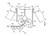
- the side view of a manufacturing apparatus The side view of the manufacturing device concerning a modification.
- the manufacturing apparatus 10 transports a supply unit 20 that supplies the molten glass MG, a pair of forming rolls 30 that rolls the molten glass MG to form a plate, and a rolled glass plate PG. It includes a transport section 40 and a cover mechanism 50 for adjusting the temperature of the forming roll 30.
- width direction X the direction in which the rotation axes RX1 and RX2 of the pair of forming rolls 30 extend is referred to as “width direction X”, and the direction in which the transport unit 40 transports the glass plate PG is referred to as “transport direction F”.
- transport direction F the direction in which the transport unit 40 transports the glass plate PG is referred to as “transport direction Z”.
- the supply unit 20 is provided with a supply port 21 through which the molten glass MG flows down.
- the supply port 21 is a substantially elliptical opening whose longitudinal direction is the width direction X.
- the molten glass MG is supplied to the supply unit 20 from a melting furnace (not shown) via a feeder. It is assumed that the molten glass MG continues to flow down from the supply unit 20 of the present embodiment so as not to hinder the replacement of the forming roll 30 even when the forming roll 30 is replaced.
- the pair of forming rolls 30 have a substantially columnar shape and are formed of metal.
- the pair of forming rolls 30 are arranged at intervals in the transport direction F.
- the pair of forming rolls 30 may have a heat generating mechanism for raising the temperature and a cooling mechanism for cooling inside.
- the forming roll 30 disposed downstream in the transport direction is also referred to as a “first forming roll 31”
- the forming roll 30 disposed upstream in the transport direction is referred to as a “second forming roll 32”.
- the pair of forming rolls 30 rotate so as to entrain the liquid pool of the molten glass MG, and roll the molten glass MG.
- the pair of forming rolls 30 form the molten glass MG into the glass plate PG.
- the transport unit 40 has a plurality of transport rollers 41 arranged such that the rotation axis is oriented in the width direction X.
- the transport rollers 41 are arranged at intervals in the transport direction F.
- the transport unit 40 transports the glass plate PG toward the annealing furnace 60 for gradually cooling the glass plate PG by rotating the transport roller 41 on which the glass plate PG is placed in the same direction.
- the cover mechanism 50 has a cover 51 having a flat plate shape, and a fixed shaft 52 fixed to the cover 51.
- the cover 51 is formed in a rectangular plate shape by, for example, a metal material.
- the cover 51 can have a long side in the width direction X.
- the length of the long side of the cover 51 that is, the width W1 of the cover 51 in the longitudinal direction (width direction X) is greater than the width W2 of the second forming roll 32 in the axial direction (also referred to as the axial length of the second forming roll 32). Is also long.
- the length D1 in the short direction of the cover 51 (also referred to as the length of the short side of the cover 51) is longer than the distance D2 from the lower surface of the supply unit 20, that is, the supply port 21 to the upper end of the second forming roll 32. long. Further, the length D1 in the short direction of the cover 51 is longer than the distance D5 from the supply port 21 of the supply unit 20 to the rotation axis RX2 of the second forming roll 32.
- the cover 51 is disposed behind the second forming roll 32 so as to be displaceable between an approach position P1 approaching the second forming roll 32 and a retracted position P2 separated from the second forming roll 32.
- the cover 51 covers from the lower end of the supply unit 20 to the center of the second forming roll 32 in the vertical direction Z when located at the approach position P1 indicated by a solid line in FIG. In other words, even when the cover 51 is located at the approach position P1, the lower end of the second forming roll 32 is exposed in the horizontal direction.
- the cover 51 is at the approach position P ⁇ b> 1
- the lower end of the cover 51 can be located below the upper end of the second forming roll 32 and above the lower end of the second forming roll 32.
- the lower end of the cover 51 at the approach position P1 is located below the rotation axis RX2 of the second forming roll 32 and above the lower end of the second forming roll 32.
- the cover 51 extends in the width direction X (axial direction). Cover the forming roll 32.
- the back surface 511 facing the second forming roll 32 has at least reflectivity for infrared rays, and is configured to reflect heat toward the second forming roll 32.
- the back surface 511 of the cover 51 is made a mirror surface to increase the reflectance.
- the cover 51 is preferably provided with a reinforcing structure such as a reinforcing rib in order to suppress thermal deformation.
- the cover 51 is displaced between the approach position P1 and the retreat position P2 as the fixed shaft 52 of the cover 51 rotates around the axis.
- the cover 51 may be configured to be manually rotated by an operator, or may be configured to be rotated by power of a motor or the like. Further, it is preferable that the cover 51 be configured to be able to stop at an arbitrary position between the approach position P1 and the retreat position P2.
- the manufacturing apparatus 10 sets the cover 51 as shown by a solid line in FIG. Is displaced to the approach position P ⁇ b> 1, heat can be prevented from escaping from the second forming roll 32. More specifically, the manufacturing apparatus 10 blocks the cool air flowing toward the second forming roll 32 with the cover 51, confine heat in the space between the second forming roll 32 and the cover 51, or increases the temperature of the cover 51. Heat can be radiated toward the second forming roll 32. Thus, the manufacturing apparatus 10 can quickly raise the temperature of the second forming roll 32.
- the manufacturing apparatus 10 moves the cover 51 to the retracted position P2 as shown by a two-dot chain line in FIG. By displacing, the heat can be released from the second forming roll 32. That is, the manufacturing apparatus 10 can suppress an excessive temperature rise of the second forming roll 32.
- the manufacturing apparatus 10 adjusts the temperature of the first forming roll 31 by adjusting the temperature of the second forming roll 32. Can also be performed indirectly.
- the manufacturing apparatus 10 adjusts the temperature of the pair of forming rolls 30 by displacing the cover 51 so that the distance between the second forming roll 32 and the cover 51 changes.
- the manufacturing apparatus 10 can quickly set the temperature of the pair of forming rolls 30 to a temperature suitable for rolling the molten glass MG. That is, the manufacturing apparatus 10 can reduce downtime during which the glass plate PG cannot be manufactured, for example, when the pair of forming rolls 30 are replaced.
- the cover 51 when the cover 51 is located at the approach position P ⁇ b> 1, the cover 51 covers a range from the supply unit 20 to the second forming roll 32. For this reason, the temperature of the molten glass MG flowing down from the supply unit 20 to the pair of forming rolls 30 does not easily decrease. Accordingly, the manufacturing apparatus 10 can quickly raise the temperature of the pair of forming rolls 30 by disposing the cover 51 at the approach position P1.
- the first forming roll 31 located in the transport direction F has a longer contact time with the rolled glass plate PG than the second forming roll 32. For this reason, the amount of heat transferred from the glass plate PG is larger in the first forming roll 31 than in the second forming roll 32. Therefore, by providing the cover 51 that covers only the second forming roll 32, the manufacturing apparatus 10 can suppress the first forming roll 31 from excessively heating. In addition, the manufacturing apparatus 10 can quickly raise the temperature of the second forming roll 32 by providing the cover 51 that covers the second forming roll 32.
- the manufacturing apparatus 10 exposes the lower part of the second forming roll 32 in the horizontal direction even when the cover 51 is located at the approach position P1. For this reason, it becomes easy for an operator to visually check the state of the second forming roll 32 or to check the state with a measuring instrument. For example, the worker can estimate the temperature of the second forming roll 32 based on the result of viewing the second forming roll 32 and adjust the distance between the second forming roll 32 and the cover 51.
- the manufacturing apparatus 10 transfers heat radiated from the second forming roll 32 and the molten glass MG toward the cover 51 to the second side.
- the light can be reflected by the forming roll 32. Therefore, by arranging the cover 51 at the approach position P1, the manufacturing apparatus 10 can quickly raise the temperature of the second forming roll 32 as necessary. In addition, the manufacturing apparatus 10 can suppress thermal deformation of the cover 51 because the temperature of the cover 51 does not easily rise.
- the manufacturing apparatus 10 adopts a configuration in which the temperature of the forming roll 30 is increased only by the heat transfer from the molten glass MG, the temperature of the forming glass 30 may be raised quickly by increasing the temperature of the molten glass MG. Then, the forming roll 30 easily reaches the service limit early.
- the manufacturing apparatus 10 having the above-described configuration employs a configuration in which the cover 51 is provided to promote the temperature rise of the forming roll 30, it is possible to suppress the forming roll 30 from reaching the service limit early.
- the manufacturing apparatus 10A includes a first cover mechanism 70 and a second cover mechanism 80.
- the first cover mechanism 70 has a first cover 71 that covers the first forming roll 31 and a first fixed shaft 72 that is fixed to the first cover 71.
- the first cover 71 has a rectangular plate shape. The width of the first cover 71 in the longitudinal direction is longer than the width of the first forming roll 31 in the axial direction, and the length D3 of the first cover 71 in the short direction is determined from the supply port 21 of the supply unit 20 to the first molding.
- the first cover 71 is disposed in front of the first forming roll 31 so as to be displaceable between an approach position P1 approaching the first forming roll 31 and a retreat position P2 retracting from the first forming roll 31.
- the second cover mechanism 80 has the same configuration as the cover mechanism 50 in the above embodiment. That is, the second cover mechanism 80 has the second cover 81 corresponding to the cover 51 and the second fixed shaft 82 corresponding to the fixed shaft 52.
- the width of the first cover 71 in the longitudinal direction is equal to the width of the second cover 81 in the longitudinal direction, and the length D3 of the first cover 71 in the transverse direction is greater than the length D4 of the second cover 81 in the transverse direction. Is also short. For this reason, the area of the first cover 71 is smaller than the area of the second cover 81.
- the area where the first forming roll 31 is covered by the first cover 71 arranged at the approach position P1 is smaller than the area where the second forming roll 32 is covered by the second cover 81 arranged at the approach position P1. .
- the length D3 of the first cover 71 in the short direction is longer than the distance D2 from the lower surface (or the supply port 21) of the supply unit 20 to the upper end of the second forming roll 32.
- the first forming roll 31 located in the transport direction F has a longer contact time with the rolled glass plate PG than the second forming roll 32. That is, the first forming roll 31 has a larger amount of heat transferred from the glass plate PG than the second forming roll 32.
- the manufacturing apparatus 10A can prevent the first forming roll 31 from being excessively heated, and The temperature can be raised quickly if necessary.
- the length D3 in the short direction of the first cover 71 is shorter than the length D4 in the short direction of the second cover 81, the first cover 71 is transferred to the transfer unit 40 and the transfer unit 40. The possibility of interference with the glass plate PG can be reduced.
- the areas of the first cover 71 and the second cover 81 may be equal.
- the cover 51 may be configured to be displaced in a manner different from the above-described embodiment as long as the cover 51 can be displaced between the approach position P1 and the retreat position P2.
- the cover 51 may be configured so as to be displaced between the approach position P1 and the retreat position P2 by reciprocating linearly in the width direction X or by expanding and contracting in a bellows shape. It may be configured to be displaced between the approach position P1 and the retreat position P2 by being wound up in a roll shape or developed in a screen shape.
- the cover 51 may include a first cover that covers a central portion of the second forming roll 32 in the axial direction, and a second cover that covers both ends of the second forming roll 32 in the axial direction.
- first cover and the second cover may be simultaneously rotated.
- the temperature at both ends in the axial direction of the second forming roll 32 is lower than the temperature at the center, only the second cover is brought closer to the second forming roll 32 or only the first cover is moved to the second forming roll. 2 It may be kept away from the forming roll 32.
- the cover 51 may have a side wall that covers an end surface of the forming roll 30 in the axial direction. According to this, the manufacturing apparatus 10 can further enhance the heat retaining effect of the forming roll 30. -The manufacturing apparatus 10 may adjust the position of the cover 51 in detail according to the temperature of the second forming roll 32. According to this, the manufacturing apparatus 10 can easily maintain the temperature of the second forming roll 32 at a desired temperature. For example, the cover 51 may be moved stepwise or steplessly so that the lower the temperature of the second forming roll 32 is, the shorter the distance between the cover 51 and the second forming roll 32 is.
- the back surface 511 of the cover 51 facing the second forming roll 32 may not be a mirror surface, depending on the specifications of the manufacturing apparatus 10 such as the cover 51 having a satisfactory level of temperature control performance.
- the degree of exposure of the second forming roll 32 in the horizontal direction when the cover 51 is disposed at the approach position P1 may be changed as appropriate.
- the cover 51 may cover the entirety from the upper end to the lower end of the second forming roll 32, or may cover only the upper part of the second forming roll 32.
- a glass plate manufacturing apparatus (10) includes: A plurality of forming rolls (31, 32) configured to continuously roll fluidized molten glass (MP) continuously flowing down from the molten glass source (20); A movable cover (51; 71; 81) provided near the plurality of forming rolls (31, 32); The movable cover (51; 71; 81) changes the distance between the movable cover and the plurality of forming rolls (31, 32) in accordance with the temperature of the plurality of forming rolls (31, 32).
- the plurality of forming rolls (31, 32) can be configured to facilitate adjusting to a predetermined forming roll temperature range.
- the movable cover (51; 71; 81) is provided with an empty space from one of the plurality of forming rolls (31, 32). Only one can be provided in between.
- a glass sheet manufacturing apparatus (10) conveys a plate-shaped continuous glass ribbon (PG) rolled by the plurality of forming rolls (31, 32) in a conveying direction (F).
- a plurality of transport rollers (41) for performing The movable cover (51) may be provided further upstream of the most upstream transport roller (41) which is the most upstream in the transport direction (F) among the plurality of transport rollers (41).
- the plurality of forming rolls (31, 32) are more than the first forming roll (31) and the first forming roll (31).
- a second forming roll (32) provided upstream in the transport direction (F)
- the movable cover (51) is provided with an empty space interposed therebetween from the second forming roll (32), and the movable cover (51) is provided in accordance with the temperature of the second forming roll (32). It can be configured to change the distance between the movable cover and the second forming roll (32).
- the movable cover (51) includes: The first in which the distance between the cover (51) and the second forming roll (32) is the smallest or the heat retaining ability or the heating ability of the cover (51) with respect to the second forming roll (32) is the largest.
- Position (P1) The second in which the distance between the cover (51) and the second forming roll (32) is the largest or the heat retaining ability or the heating ability of the cover (51) with respect to the second forming roll (32) is the smallest. It can be configured to move to and from a position (P2).
- the movable cover (51) rotates in parallel with the rotation axes (RX1, RX2) of the plurality of forming rolls (31, 32). It can be configured to pivot about an axis (52).
- the movable cover (51) has a longer side longer than an axial length (W2) of the plurality of forming rolls (31, 32). It can be a rectangular plate having (W1).
- 10, 10A manufacturing apparatus
- 20 supply unit
- 21 supply port
- 30 forming roll
- 31 first forming roll
- 32 second forming roll
- 40 transport unit
- 41 transport roller
- 50 cover mechanism Reference numerals 51, cover 511, back surface, 52, fixed shaft, 60, annealing furnace
- 70 first cover mechanism, 71, first cover, 72, first fixed shaft, 80, second cover mechanism, 81, second cover , 82: second fixed shaft
- MG molten glass
- PG glass plate
- F transport direction
- X width direction
- Z vertical direction.
Landscapes
- Chemical & Material Sciences (AREA)
- Engineering & Computer Science (AREA)
- Materials Engineering (AREA)
- Organic Chemistry (AREA)
- Re-Forming, After-Treatment, Cutting And Transporting Of Glass Products (AREA)
Abstract
成形ロールを速やかに昇温できるガラス板PGの製造装置10は、供給部20から流下する溶融ガラスMGを板状に圧延する一対の成形ロール30(31,32)と、第2成形ロール32を軸方向に亘って覆うカバー51と、を備える。カバー51は、第2成形ロール32に接近する接近位置P1及び第2成形ロール32から離れる退避位置P2の間で変位する。
Description
本発明は、ガラス板の製造装置及びガラス板の製造方法に関する。
特許文献1には、フィーダーから排出された溶融ガラスを一対の成形ロールで圧延することで溶融ガラスを板状に成形する、いわゆるロールアウト法によるガラス板の製造装置が記載されている。
ロールアウト法によるガラス板の製造装置において、成形ロールには耐用限度が設定されているため、定期的に成形ロールの交換作業が行われる。ところが、交換直後の成形ロールの温度は溶融ガラスの圧延に適した温度よりも低く、製造装置は、成形ロールの温度が溶融ガラスの圧延に適した温度となるまでガラス板の製造を中断する必要が生じる。本明細書において、溶融ガラスの圧延に適した温度は、所定の成形ロール温度範囲と呼称することがある。なお、こうした課題は、成形ロールの交換時に限らず、停止状態の製造装置を再稼働させる場合にも概ね共通する課題である。本発明の目的は、成形ロールを速やかに昇温できるガラス板の製造装置及びガラス板の製造方法を提供することにある。
以下、上記課題を解決するための手段及びその作用効果について記載する。
上記課題を解決するガラス板の製造装置は、溶融ガラスの供給部から流下する前記溶融ガラスを板状に圧延する一対の成形ロールを備えるガラス板の製造装置であって、前記成形ロールを軸方向に亘って覆うカバーであって、前記成形ロールに接近する接近位置及び前記成形ロールから離れる退避位置の間で変位するカバーを備える。
上記課題を解決するガラス板の製造装置は、溶融ガラスの供給部から流下する前記溶融ガラスを板状に圧延する一対の成形ロールを備えるガラス板の製造装置であって、前記成形ロールを軸方向に亘って覆うカバーであって、前記成形ロールに接近する接近位置及び前記成形ロールから離れる退避位置の間で変位するカバーを備える。
製造装置は、成形ロールの交換直後など、成形ロールの温度が所定の成形ロール温度範囲よりも低い場合には、カバーを接近位置に変位させることで、昇温中の成形ロールから熱が逃げることを抑制できる。これにより、製造装置は、成形ロールを速やかに昇温できる。さらに、製造装置は、成形ロールが過度に昇温する場合には、カバーを退避位置に変位させることで、成形ロールから熱を逃がすことができる。こうして、製造装置は、成形ロールを速やかに昇温できる一方で、成形ロールの過度な昇温を抑制できる。
上記構成のガラス板の製造装置において、前記カバーは、前記接近位置に位置するとき、鉛直方向において、前記供給部から前記成形ロールまでの範囲を覆うことが好ましい。
上記構成によれば、供給部から成形ロールに流下する溶融ガラスの温度が低下しにくくなる。このため、製造装置は、カバーを接近位置に配置することで、溶融ガラスから成形ロールに対する伝熱量を増やすことができる。こうして、製造装置は、成形ロールを速やかに昇温できる。
上記構成によれば、供給部から成形ロールに流下する溶融ガラスの温度が低下しにくくなる。このため、製造装置は、カバーを接近位置に配置することで、溶融ガラスから成形ロールに対する伝熱量を増やすことができる。こうして、製造装置は、成形ロールを速やかに昇温できる。
上記構成のガラス板の製造装置は、前記一対の成形ロールに圧延されたガラス板を前記軸方向と交差する搬送方向に搬送する搬送部を備え、前記一対の成形ロールのうち、前記搬送方向に位置する成形ロールを第1成形ロールとし、他方の成形ロールを第2成形ロールとしたとき、前記カバーは、前記第2成形ロールを覆うことが好ましい。
上記構成によれば、搬送方向に位置する第1成形ロールは、第2成形ロールと比較して、圧延済みのガラス板と接触する時間が長くなる。このため、第1成形ロールは、第2成形ロールよりもガラス板からの伝熱量が多くなりやすい。この点、製造装置は、第2成形ロールを覆うカバーのみを設けることで、第1成形ロールの温度が所定の成形ロール温度範囲を超えて過度に昇温することを抑制できる。また、製造装置は、第2成形ロールを覆うカバーを設けることで、第2成形ロールを速やかに昇温できる。
上記構成のガラス板の製造装置は、前記一対の成形ロールに圧延されたガラス板を前記軸方向と交差する搬送方向に搬送する搬送部を備え、前記一対の成形ロールのうち、前記搬送方向に位置する成形ロールを第1成形ロールとし、他方の成形ロールを第2成形ロールとしたとき、前記カバーは、前記第1成形ロールを覆う第1カバーと、前記第2成形ロールを覆う第2カバーと、を有し、前記第1カバーの面積は、前記第2カバーの面積よりも小さいことが好ましい。
上記構成によれば、搬送方向に位置する第1成形ロールは、第2成形ロールと比較して、圧延済みのガラス板と接触する時間が長くなる。このため、第1成形ロールは、第2成形ロールよりもガラス板からの伝熱量が多くなりやすい。この点、製造装置は、第2カバーの面積を第1カバーの面積よりも大きくすることで、第1成形ロールが過度に昇温することを抑制でき、第2成形ロールを速やかに昇温できる。
上記構成のガラス板の製造装置において、前記カバーが前記接近位置に位置するとき、前記成形ロールの下部は、水平方向に露出することが好ましい。
上記構成によれば、作業者は、成形ロールの状態を目視で確認したり、測定器で状態を確認したりすることが容易となる。
上記構成によれば、作業者は、成形ロールの状態を目視で確認したり、測定器で状態を確認したりすることが容易となる。
上記構成のガラス板の製造装置において、前記カバーにおける前記成形ロールに対向する面は鏡面であることが好ましい。
上記構成の製造装置は、成形ロール及び溶融ガラスからカバーに向かって放射される熱を、成形ロールに反射できる。したがって、製造装置は、カバーを接近位置に配置することで、成形ロールを速やかに昇温できる。
上記構成の製造装置は、成形ロール及び溶融ガラスからカバーに向かって放射される熱を、成形ロールに反射できる。したがって、製造装置は、カバーを接近位置に配置することで、成形ロールを速やかに昇温できる。
上記課題を解決するガラス板の製造方法は、溶融ガラスを供給する供給部から流下する前記溶融ガラスを一対の成形ロールにより板状に成形するガラス板の製造方法であって、前記成形ロールを軸方向に亘って覆うカバーと前記成形ロールとの距離が変化するように、前記カバーを変位させることにより、前記成形ロールの温度を調整する。
上記ガラス板の製造方法は、上述したガラス板の製造装置と同等の効果を得ることができる。
上記ガラス板の製造装置及びガラス板の製造方法は、成形ロールを速やかに昇温できる。
以下、一実施形態に係るガラス板の製造装置及びガラス板の製造方法について説明する。
図1に示すように、製造装置10は、溶融ガラスMGを供給する供給部20と、溶融ガラスMGを圧延して板状に成形する一対の成形ロール30と、圧延したガラス板PGを搬送する搬送部40と、成形ロール30の温度調整を行うカバー機構50と、を備える。
図1に示すように、製造装置10は、溶融ガラスMGを供給する供給部20と、溶融ガラスMGを圧延して板状に成形する一対の成形ロール30と、圧延したガラス板PGを搬送する搬送部40と、成形ロール30の温度調整を行うカバー機構50と、を備える。
以降の説明では、一対の成形ロール30の回転軸線RX1、RX2が延びる方向を「幅方向X」とし、搬送部40がガラス板PGを搬送する方向を「搬送方向F」とする。本実施形態では、幅方向X及び搬送方向Fが直交し、幅方向X及び搬送方向Fの両方向と直交する方向が「鉛直方向Z」となる。
図2及び図3に示すように、供給部20には、溶融ガラスMGを流下させる供給口21が形成される。供給口21は、幅方向Xを長手方向とする略長円形状の開口である。供給部20には、図示しない溶融炉からフィーダーを介して溶融ガラスMGが供給される。なお、本実施形態の供給部20からは、成形ロール30の交換時であっても、成形ロール30の交換を妨げないように、溶融ガラスMGが流下され続けるものとする。
図1~図3に示すように、一対の成形ロール30は、略円柱状をなし、金属により形成される。一対の成形ロール30は、搬送方向Fに間隔をあけて配置される。一対の成形ロール30は、内部に、昇温のための発熱機構及び冷却のための冷却機構を有してもよい。以降の説明では、一対の成形ロール30において、搬送方向下流に配置される成形ロール30を「第1成形ロール31」とも言い、搬送方向上流に配置される成形ロール30を「第2成形ロール32」とも言う。つまり、製造装置10の平面視において、第1成形ロール31は搬送部40と重なるものの、第2成形ロール32は搬送部40と重ならない。
供給部20の供給口21から一対の成形ロール30の間に流下した溶融ガラスMGは、幅方向Xに広がる。一対の成形ロール30は、溶融ガラスMGの液溜まりを巻き込むように回転し、溶融ガラスMGを圧延する。こうして、一対の成形ロール30は、溶融ガラスMGをガラス板PGに成形する。
図1に示すように、搬送部40は、回転軸線が幅方向Xを向くように配置される複数の搬送ローラー41を有する。搬送ローラー41は、搬送方向Fに間隔をあけて配置される。搬送部40は、ガラス板PGを載せた搬送ローラー41を同一方向に回転させることにより、ガラス板PGを、ガラス板PGを徐冷するための徐冷炉60に向けて搬送する。
図1~図3に示すように、カバー機構50は、平板状をなすカバー51と、カバー51に固定される固定軸52と、を有する。
カバー51は、例えば、金属材料により、矩形板状に形成される。図2に示すように、カバー51は、幅方向Xに長辺を有することができる。カバー51の長辺の長さ、すなわち、長手方向(幅方向X)におけるカバー51の幅W1は、第2成形ロール32の軸方向における幅W2(第2成形ロール32の軸長ともいう)よりも長い。また、カバー51の短手方向における長さD1(カバー51の短辺の長さともいう)は、供給部20の下面、すなわち供給口21から第2成形ロール32の上端までの距離D2よりも長い。さらに、カバー51の短手方向における長さD1は、供給部20の供給口21から第2成形ロール32の回転軸線RX2までの距離D5よりも長い。
カバー51は、例えば、金属材料により、矩形板状に形成される。図2に示すように、カバー51は、幅方向Xに長辺を有することができる。カバー51の長辺の長さ、すなわち、長手方向(幅方向X)におけるカバー51の幅W1は、第2成形ロール32の軸方向における幅W2(第2成形ロール32の軸長ともいう)よりも長い。また、カバー51の短手方向における長さD1(カバー51の短辺の長さともいう)は、供給部20の下面、すなわち供給口21から第2成形ロール32の上端までの距離D2よりも長い。さらに、カバー51の短手方向における長さD1は、供給部20の供給口21から第2成形ロール32の回転軸線RX2までの距離D5よりも長い。
カバー51は、第2成形ロール32に接近する接近位置P1及び第2成形ロール32から離れた退避位置P2の間で変位できるように、第2成形ロール32の後方に配置される。カバー51は、図3に実線で示す接近位置P1に位置するとき、鉛直方向Zにおいて、供給部20の下端部から第2成形ロール32の中央部までを覆う。言い換えれば、カバー51は、接近位置P1に位置するときでも、第2成形ロール32の下端部を水平方向に露出させる。例えば、カバー51が接近位置P1にあるとき、カバー51の下端は、第2成形ロール32の上端よりも下で第2成形ロール32の下端よりも上に位置することができる。図示した例では、接近位置P1にあるカバー51の下端は、第2成形ロール32の回転軸線RX2よりも下で第2成形ロール32の下端よりも上に位置する。また、カバー51は、図3に実線で示す接近位置P1及び図3に二点鎖線で示す退避位置P2の何れに位置するかに関わらず、幅方向X(軸方向)に亘って、第2成形ロール32を覆う。
カバー51において、第2成形ロール32を向く裏面511は、少なくとも赤外線に対する反射性を有しており、第2成形ロール32に向けて熱を反射するように構成される。例えば、カバー51の裏面511は、反射率を高くするために鏡面とされる。カバー51には、熱変形を抑制するために、補強リブなどの補強構造を設けることが好ましい。
そして、カバー51は、カバー51の固定軸52が軸線回りに回転することで、接近位置P1及び退避位置P2の間で変位する。ここで、カバー51は、作業者が手作業で回転するように構成してもよいし、モーターなどの動力によって回転するように構成してもよい。また、カバー51は、接近位置P1及び退避位置P2の間の任意の位置で停止できるように構成することが好ましい。
本実施形態の作用及び効果について説明する。
(1)製造装置10は、第2成形ロール32の交換直後など、第2成形ロール32の温度が所定の成形ロール温度範囲よりも低い場合には、図3に実線で示すように、カバー51を接近位置P1に変位させることで、第2成形ロール32から熱が逃げることを抑制できる。詳しくは、製造装置10は、第2成形ロール32に向かって流れる冷気をカバー51で遮ったり、第2成形ロール32及びカバー51の間の空間に熱を閉じ込めたり、昇温されたカバー51から第2成形ロール32に向けて熱を放射させたりできる。こうして、製造装置10は、第2成形ロール32を速やかに昇温できる。さらに、製造装置10は、第2成形ロール32の温度が所定の成形ロール温度範囲を超えて過度に上昇する場合には、図3に二点鎖線で示すように、カバー51を退避位置P2に変位させることで、第2成形ロール32から熱を逃がすことができる。つまり、製造装置10は、第2成形ロール32の過度な昇温を抑制できる。
(1)製造装置10は、第2成形ロール32の交換直後など、第2成形ロール32の温度が所定の成形ロール温度範囲よりも低い場合には、図3に実線で示すように、カバー51を接近位置P1に変位させることで、第2成形ロール32から熱が逃げることを抑制できる。詳しくは、製造装置10は、第2成形ロール32に向かって流れる冷気をカバー51で遮ったり、第2成形ロール32及びカバー51の間の空間に熱を閉じ込めたり、昇温されたカバー51から第2成形ロール32に向けて熱を放射させたりできる。こうして、製造装置10は、第2成形ロール32を速やかに昇温できる。さらに、製造装置10は、第2成形ロール32の温度が所定の成形ロール温度範囲を超えて過度に上昇する場合には、図3に二点鎖線で示すように、カバー51を退避位置P2に変位させることで、第2成形ロール32から熱を逃がすことができる。つまり、製造装置10は、第2成形ロール32の過度な昇温を抑制できる。
なお、第2成形ロール32は、第1成形ロール31と溶融ガラスMGを介して熱を授受できるため、製造装置10は、第2成形ロール32の温度調整により、第1成形ロール31の温度調整を間接的に行うこともできる。
こうして、製造装置10は、第2成形ロール32及びカバー51の距離が変化するようにカバー51を変位させることにより、一対の成形ロール30の温度を調整する。その結果、製造装置10は、速やかに、一対の成形ロール30の温度を溶融ガラスMGの圧延に適した温度にできる。つまり、製造装置10は、一対の成形ロール30の交換時などに、ガラス板PGの製造ができないダウンタイムを短縮できる。
(2)図3に示すように、カバー51は、接近位置P1に位置するとき、供給部20から第2成形ロール32までの範囲を覆う。このため、供給部20から一対の成形ロール30に流下する溶融ガラスMGの温度が低下しにくくなる。したがって、製造装置10は、カバー51を接近位置P1に配置することで、一対の成形ロール30を速やかに昇温できる。
(3)図3に示すように、搬送方向Fに位置する第1成形ロール31は、第2成形ロール32と比較して、圧延済みのガラス板PGと接触する時間が長い。このため、第1成形ロール31は、第2成形ロール32よりもガラス板PGからの伝熱量が多くなる。したがって、製造装置10は、第2成形ロール32のみを覆うカバー51を設けることで、第1成形ロール31が過度に昇温することを抑制できる。また、製造装置10は、第2成形ロール32を覆うカバー51を設けることで、第2成形ロール32を速やかに昇温できる。
(4)図3に示すように、製造装置10は、カバー51を接近位置P1に配置したときでも、第2成形ロール32の下部を水平方向に露出させる。このため、作業者は、第2成形ロール32の状態を目視で確認したり、測定器で状態を確認したりすることが容易となる。例えば、作業者は、第2成形ロール32を目視した結果に基づいて第2成形ロール32の温度を推定し、第2成形ロール32とカバー51との距離を調整できる。
(5)カバー51の第2成形ロール32に対向する裏面511は鏡面であるため、製造装置10は、第2成形ロール32及び溶融ガラスMGからカバー51に向かって放射される熱を、第2成形ロール32に反射できる。したがって、製造装置10は、カバー51を接近位置P1に配置することで、第2成形ロール32を必要に応じて速やかに昇温できる。また、製造装置10は、カバー51が昇温しにくくなることで、カバー51の熱変形を抑制できる。
(6)製造装置10が成形ロール30を溶融ガラスMGからの伝熱のみで昇温する構成を採用する場合において、溶融ガラスMGの温度を高くすることで成形ロール30を速やかに昇温させようとすると、成形ロール30が早期に耐用限度に達しやすくなる。この点、上記構成の製造装置10は、カバー51を設けることで成形ロール30の昇温を促進する構成を採用するため、成形ロール30が早期に耐用限度に達することを抑制できる。
本実施形態は、以下のように変更して実施することができる。本実施形態及び以下の変更例は、技術的に矛盾しない範囲で互いに組み合わせて実施することができる。
・上記製造装置10は、図4に示す製造装置10Aとしてもよい。図4に示すように、製造装置10Aは、第1カバー機構70と、第2カバー機構80と、を備える。第1カバー機構70は、第1成形ロール31を覆う第1カバー71と、第1カバー71に固定される第1固定軸72と、を有する。第1カバー71は、矩形板状をなしている。第1カバー71の長手方向における幅は、第1成形ロール31の軸方向における幅よりも長く、第1カバー71の短手方向における長さD3は、供給部20の供給口21から第1成形ロール31の回転軸線RX1までの距離と略等しい。そして、第1カバー71は、第1成形ロール31に接近する接近位置P1と第1成形ロール31から退避する退避位置P2との間で変位できるように、第1成形ロール31の前方に配置される。一方、第2カバー機構80は、上記実施形態におけるカバー機構50と同一の構成である。つまり、第2カバー機構80は、カバー51に相当する第2カバー81と、固定軸52に相当する第2固定軸82と、を有する。
・上記製造装置10は、図4に示す製造装置10Aとしてもよい。図4に示すように、製造装置10Aは、第1カバー機構70と、第2カバー機構80と、を備える。第1カバー機構70は、第1成形ロール31を覆う第1カバー71と、第1カバー71に固定される第1固定軸72と、を有する。第1カバー71は、矩形板状をなしている。第1カバー71の長手方向における幅は、第1成形ロール31の軸方向における幅よりも長く、第1カバー71の短手方向における長さD3は、供給部20の供給口21から第1成形ロール31の回転軸線RX1までの距離と略等しい。そして、第1カバー71は、第1成形ロール31に接近する接近位置P1と第1成形ロール31から退避する退避位置P2との間で変位できるように、第1成形ロール31の前方に配置される。一方、第2カバー機構80は、上記実施形態におけるカバー機構50と同一の構成である。つまり、第2カバー機構80は、カバー51に相当する第2カバー81と、固定軸52に相当する第2固定軸82と、を有する。
第1カバー71の長手方向における幅は、第2カバー81の長手方向における幅と等しく、第1カバー71の短手方向における長さD3は、第2カバー81の短手方向における長さD4よりも短い。このため、第1カバー71の面積は、第2カバー81の面積よりも小さくなる。そして、接近位置P1に配置される第1カバー71によって第1成形ロール31が覆われる面積は、接近位置P1に配置される第2カバー81によって第2成形ロール32が覆われる面積よりも小さくなる。なお、第1カバー71の短手方向における長さD3は、供給部20の下面(または供給口21)から第2成形ロール32の上端までの距離D2よりも長い。
上述した通り、搬送方向Fに位置する第1成形ロール31は、第2成形ロール32と比較して、圧延済みのガラス板PGと接触する時間が長い。つまり、第1成形ロール31は、第2成形ロール32よりもガラス板PGから伝熱される熱量が多い。この点、製造装置10Aは、第2カバー81の面積を第1カバー71の面積よりも大きくすることで、第1成形ロール31が過度に昇温することを抑制でき、第2成形ロール32を必要に応じて速やかに昇温できる。また、第1カバー71の短手方向における長さD3を第2カバー81の短手方向における長さD4よりも短くしたことで、第1カバー71が搬送部40及び搬送部40に搬送されるガラス板PGに干渉するおそれを低減できる。
・図4に示す変更例において、第1カバー71及び第2カバー81の面積は等しくてもよい。
・カバー51は、接近位置P1及び退避位置P2の間を変位できる構成であれば、上記実施形態と異なる態様で変位する構成としてもよい。
・カバー51は、接近位置P1及び退避位置P2の間を変位できる構成であれば、上記実施形態と異なる態様で変位する構成としてもよい。
・例えば、カバー51は、幅方向Xに直線的に往復移動したり、蛇腹状に伸縮したりすることで、接近位置P1及び退避位置P2の間を変位するように構成してもよいし、ロール状に巻き重ねたり、スクリーン状に展開したりすることで、接近位置P1及び退避位置P2の間を変位するように構成してもよい。
・カバー51は、第2成形ロール32の軸方向における中央部を覆う第1カバーと、第2成形ロール32の軸方向における両端部を覆う第2カバーと、を有してもよい。この場合、第2成形ロール32が幅方向Xに亘って温度が低くなったり高くなったりする場合には、第1カバー及び第2カバーを同時に回転させてもよい。一方、第2成形ロール32の軸方向における両端部の温度が中央部の温度に比べて低くなる場合には、第2カバーだけを第2成形ロール32に接近させたり、第1カバーだけを第2成形ロール32から遠ざけたりしてもよい。
・カバー51は、成形ロール30の軸方向における端面を覆う側壁を有してもよい。これによれば、製造装置10は、成形ロール30の保温効果をより高めることができる。
・製造装置10は、第2成形ロール32の温度に応じて、カバー51の位置を詳細に調整してもよい。これによれば、製造装置10は、第2成形ロール32の温度を所望の温度に維持しやすくなる。例えば、第2成形ロール32の温度が低いほどカバー51と第2成形ロール32との距離が短くなるように、カバー51は段階的にまたは無段階で移動されてよい。
・製造装置10は、第2成形ロール32の温度に応じて、カバー51の位置を詳細に調整してもよい。これによれば、製造装置10は、第2成形ロール32の温度を所望の温度に維持しやすくなる。例えば、第2成形ロール32の温度が低いほどカバー51と第2成形ロール32との距離が短くなるように、カバー51は段階的にまたは無段階で移動されてよい。
・上記実施形態において、例えばカバー51が満足できるレベルの温度調整性能を有するなどの製造装置10の仕様によっては、カバー51の第2成形ロール32に対向する裏面511は鏡面でなくてもよい。
・上記実施形態において、カバー51を接近位置P1に配置したときの第2成形ロール32の水平方向に対する露出度合は、適宜変更してもよい。例えば、カバー51は、第2成形ロール32の上端から下端まで全てを覆ってもよいし、第2成形ロール32の上部だけを覆ってもよい。
本開示には以下の構成が含まれる。限定ではなく理解の補助のために、図示した実施形態の参照符号を付した。
[付記1]非限定的な例に従うガラス板製造装置(10)は、
溶融ガラス源(20)から連続的に流下する流動性の溶融ガラス(MP)を連続的に圧延するように構成された複数の成形ロール(31、32)と、
前記複数の成形ロール(31、32)の近傍に設けられた可動カバー(51;71;81)とを備えることができ、
前記可動カバー(51;71;81)は、前記複数の成形ロール(31、32)の温度に応じて当該可動カバーと前記複数の成形ロール(31、32)との距離を変更して、前記複数の成形ロール(31、32)を所定の成形ロール温度範囲に調整するのを促進するように構成されることができる。
[付記1]非限定的な例に従うガラス板製造装置(10)は、
溶融ガラス源(20)から連続的に流下する流動性の溶融ガラス(MP)を連続的に圧延するように構成された複数の成形ロール(31、32)と、
前記複数の成形ロール(31、32)の近傍に設けられた可動カバー(51;71;81)とを備えることができ、
前記可動カバー(51;71;81)は、前記複数の成形ロール(31、32)の温度に応じて当該可動カバーと前記複数の成形ロール(31、32)との距離を変更して、前記複数の成形ロール(31、32)を所定の成形ロール温度範囲に調整するのを促進するように構成されることができる。
[付記2]非限定的な例に従うガラス板製造装置(10)において、前記可動カバー(51;71;81)は、前記複数の成形ロール(31、32)のうちの一つから空の空間のみを間に挟んで設けられることができる。
[付記3]非限定的な例に従うガラス板製造装置(10)は、前記複数の成形ロール(31、32)によって圧延された板状の連続ガラスリボン(PG)を搬送方向(F)に搬送するための複数の搬送ローラー(41)をさらに備えることができ、
前記可動カバー(51)は、前記複数の搬送ローラー(41)のうち前記搬送方向(F)において最上流にある最上流搬送ローラー(41)よりもさらに上流に設けられることができる。
前記可動カバー(51)は、前記複数の搬送ローラー(41)のうち前記搬送方向(F)において最上流にある最上流搬送ローラー(41)よりもさらに上流に設けられることができる。
[付記4]非限定的な例に従うガラス板製造装置(10)において、前記複数の成形ロール(31、32)は、第1成形ロール(31)と、前記第1成形ロール(31)よりも前記搬送方向(F)において上流に設けられた第2成形ロール(32)とを含むことができ、
前記可動カバー(51)は、前記第2成形ロール(32)から空の空間を間に挟んで設けられ、前記可動カバー(51)は、前記第2成形ロール(32)の温度に応じて、当該可動カバーと前記第2成形ロール(32)との距離を変更するように構成されることができる。
前記可動カバー(51)は、前記第2成形ロール(32)から空の空間を間に挟んで設けられ、前記可動カバー(51)は、前記第2成形ロール(32)の温度に応じて、当該可動カバーと前記第2成形ロール(32)との距離を変更するように構成されることができる。
[付記5]非限定的な例に従うガラス板製造装置(10)において、前記可動カバー(51)は、
当該カバー(51)と前記第2成形ロール(32)との距離が最小であるかまたは前記第2成形ロール(32)に対する当該カバー(51)の保温能力または加温能力が最大である第1位置(P1)と、
当該カバー(51)と前記第2成形ロール(32)との距離が最大であるかまたは前記第2成形ロール(32)に対する当該カバー(51)の保温能力または加温能力が最小である第2位置(P2)と
の間で移動するように構成されることができる。
当該カバー(51)と前記第2成形ロール(32)との距離が最小であるかまたは前記第2成形ロール(32)に対する当該カバー(51)の保温能力または加温能力が最大である第1位置(P1)と、
当該カバー(51)と前記第2成形ロール(32)との距離が最大であるかまたは前記第2成形ロール(32)に対する当該カバー(51)の保温能力または加温能力が最小である第2位置(P2)と
の間で移動するように構成されることができる。
[付記6]非限定的な例に従うガラス板製造装置(10)において、前記可動カバー(51)は、前記複数の成形ロール(31、32)の回転軸線(RX1、RX2)と平行な回動軸(52)の周りで回動するように構成されることができる。
[付記7]非限定的な例に従うガラス板製造装置(10)において、前記可動カバー(51)は、前記複数の成形ロール(31、32)の軸方向長さ(W2)よりも長い長辺(W1)を有する矩形板であることができる。
10,10A…製造装置、20…供給部、21…供給口、30…成形ロール、31…第1成形ロール、32…第2成形ロール、40…搬送部、41…搬送ローラー、50…カバー機構、51…カバー、511…裏面、52…固定軸、60…徐冷炉、70…第1カバー機構、71…第1カバー、72…第1固定軸、80…第2カバー機構、81…第2カバー、82…第2固定軸、MG…溶融ガラス、PG…ガラス板、F…搬送方向、X…幅方向、Z…鉛直方向。
Claims (7)
- 溶融ガラスの供給部から流下する前記溶融ガラスを板状に圧延する一対の成形ロールを備えるガラス板の製造装置であって、
前記成形ロールを軸方向に亘って覆うカバーであって、前記成形ロールに接近する接近位置及び前記成形ロールから離れる退避位置の間で変位するカバーを備える
ことを特徴とするガラス板の製造装置。 - 前記カバーは、前記接近位置に位置するとき、鉛直方向において、前記供給部から前記成形ロールまでの範囲を覆う
請求項1に記載のガラス板の製造装置。 - 前記一対の成形ロールに圧延されたガラス板を前記軸方向と交差する搬送方向に搬送する搬送部を備え、
前記一対の成形ロールのうち、前記搬送方向に位置する成形ロールを第1成形ロールとし、他方の成形ロールを第2成形ロールとしたとき、
前記カバーは、前記第2成形ロールを覆う
請求項1又は請求項2に記載のガラス板の製造装置。 - 前記一対の成形ロールに圧延されたガラス板を前記軸方向と交差する搬送方向に搬送する搬送部を備え、
前記一対の成形ロールのうち、前記搬送方向に位置する成形ロールを第1成形ロールとし、他方の成形ロールを第2成形ロールとしたとき、
前記カバーは、前記第1成形ロールを覆う第1カバーと、前記第2成形ロールを覆う第2カバーと、を有し、
前記第1カバーの面積は、前記第2カバーの面積よりも小さい
請求項1又は請求項2に記載のガラス板の製造装置。 - 前記カバーが前記接近位置に位置するとき、前記成形ロールの下部は、水平方向に露出する
請求項1~請求項4の何れか一項に記載のガラス板の製造装置。 - 前記カバーにおいて、前記成形ロールに対向する面は鏡面である
請求項1~請求項5の何れか一項に記載のガラス板の製造装置。 - 溶融ガラスを供給する供給部から流下する前記溶融ガラスを一対の成形ロールにより板状に成形するガラス板の製造方法であって、
前記成形ロールを軸方向に亘って覆うカバーと前記成形ロールとの距離が変化するように、前記カバーを変位させることにより、前記成形ロールの温度を調整する
ガラス板の製造方法。
Applications Claiming Priority (2)
| Application Number | Priority Date | Filing Date | Title |
|---|---|---|---|
| JP2018-138404 | 2018-07-24 | ||
| JP2018138404A JP2020015634A (ja) | 2018-07-24 | 2018-07-24 | ガラス板の製造装置及びガラス板の製造方法 |
Publications (1)
| Publication Number | Publication Date |
|---|---|
| WO2020021926A1 true WO2020021926A1 (ja) | 2020-01-30 |
Family
ID=69181006
Family Applications (1)
| Application Number | Title | Priority Date | Filing Date |
|---|---|---|---|
| PCT/JP2019/024682 Ceased WO2020021926A1 (ja) | 2018-07-24 | 2019-06-21 | ガラス板の製造装置及びガラス板の製造方法 |
Country Status (2)
| Country | Link |
|---|---|
| JP (1) | JP2020015634A (ja) |
| WO (1) | WO2020021926A1 (ja) |
Citations (5)
| Publication number | Priority date | Publication date | Assignee | Title |
|---|---|---|---|---|
| US1657214A (en) * | 1926-06-09 | 1928-01-24 | Pittsburgh Plate Glass Co | Apparatus for rolling glass |
| US2184908A (en) * | 1936-03-31 | 1939-12-26 | Saint Gobain | Device for regulating the temperature of metal cylinders |
| JPS59137321A (ja) * | 1983-01-27 | 1984-08-07 | シヨツト,グラスヴエルケ | 圧延機 |
| JP2014520059A (ja) * | 2011-05-31 | 2014-08-21 | コーニング インコーポレイテッド | 精密ガラスロール成形プロセスおよび装置 |
| JP2017088435A (ja) * | 2015-11-06 | 2017-05-25 | 日本電気硝子株式会社 | 板ガラス製造装置及び板ガラスの製造方法 |
-
2018
- 2018-07-24 JP JP2018138404A patent/JP2020015634A/ja active Pending
-
2019
- 2019-06-21 WO PCT/JP2019/024682 patent/WO2020021926A1/ja not_active Ceased
Patent Citations (5)
| Publication number | Priority date | Publication date | Assignee | Title |
|---|---|---|---|---|
| US1657214A (en) * | 1926-06-09 | 1928-01-24 | Pittsburgh Plate Glass Co | Apparatus for rolling glass |
| US2184908A (en) * | 1936-03-31 | 1939-12-26 | Saint Gobain | Device for regulating the temperature of metal cylinders |
| JPS59137321A (ja) * | 1983-01-27 | 1984-08-07 | シヨツト,グラスヴエルケ | 圧延機 |
| JP2014520059A (ja) * | 2011-05-31 | 2014-08-21 | コーニング インコーポレイテッド | 精密ガラスロール成形プロセスおよび装置 |
| JP2017088435A (ja) * | 2015-11-06 | 2017-05-25 | 日本電気硝子株式会社 | 板ガラス製造装置及び板ガラスの製造方法 |
Also Published As
| Publication number | Publication date |
|---|---|
| JP2020015634A (ja) | 2020-01-30 |
Similar Documents
| Publication | Publication Date | Title |
|---|---|---|
| JP7577805B2 (ja) | ガラス基板を加工する装置および方法 | |
| JP5648635B2 (ja) | ガラス板の製造方法及び製造装置 | |
| TWI520920B (zh) | 用於玻璃片之局部加熱與變形的方法及設備 | |
| KR20080083563A (ko) | 시트 형상물의 연신기 | |
| CN105392740B (zh) | 用于玻璃生产线的可再定位加热器组件以及管理生产线中玻璃温度的方法 | |
| KR101796268B1 (ko) | 소성장치 및 오븐 | |
| JPWO2009084674A1 (ja) | ガラス板成形用加熱装置及びガラス板の曲げ成形方法 | |
| FI86407B (fi) | Foerfarande och anordning foer att utjaemna temperaturprofilen i glasskivor i en med valsar foersedd ugn i en horisontalhaerdningsanordning. | |
| JP2023143795A (ja) | 厚さ測定方法及び厚さ測定装置 | |
| CN106007342B (zh) | 支承辊、玻璃制造装置、及玻璃制造方法 | |
| JP3898045B2 (ja) | 板状ガラス成形装置及び板状ガラスの成形方法 | |
| JP2020015634A (ja) | ガラス板の製造装置及びガラス板の製造方法 | |
| JP5636172B2 (ja) | ガラスの成形装置及び強化ガラス製造装置 | |
| KR102098471B1 (ko) | 이송장치 | |
| CN216804405U (zh) | 一种保护膜上料预热整平装置 | |
| JP2007519536A (ja) | 印刷版炉における及び関する改良 | |
| JP6536358B2 (ja) | 板ガラス製造装置及び板ガラスの製造方法 | |
| JP2004502631A (ja) | ガラス板の曲げ加工方法及び曲げ加工用型 | |
| TW592847B (en) | Dual roll casting machine and method of operating the casting machine | |
| JP6088115B2 (ja) | 熱間圧延機 | |
| JP6700604B2 (ja) | ガラス板製造装置及びガラス板の製造方法 | |
| KR20190046070A (ko) | 압연 보열설비 | |
| JP2009155164A (ja) | ガラスリボンの搬送方法 | |
| JP7377499B2 (ja) | シート材製造方法、塗膜形成方法、シート材製造装置及びコーター | |
| CN117020026B (zh) | 一种铝型材整形机 |
Legal Events
| Date | Code | Title | Description |
|---|---|---|---|
| 121 | Ep: the epo has been informed by wipo that ep was designated in this application |
Ref document number: 19841136 Country of ref document: EP Kind code of ref document: A1 |
|
| NENP | Non-entry into the national phase |
Ref country code: DE |
|
| 122 | Ep: pct application non-entry in european phase |
Ref document number: 19841136 Country of ref document: EP Kind code of ref document: A1 |