WO2020021910A1 - 鉛蓄電池 - Google Patents
鉛蓄電池 Download PDFInfo
- Publication number
- WO2020021910A1 WO2020021910A1 PCT/JP2019/023909 JP2019023909W WO2020021910A1 WO 2020021910 A1 WO2020021910 A1 WO 2020021910A1 JP 2019023909 W JP2019023909 W JP 2019023909W WO 2020021910 A1 WO2020021910 A1 WO 2020021910A1
- Authority
- WO
- WIPO (PCT)
- Prior art keywords
- passage
- wall
- lid
- battery case
- partition
- Prior art date
- Legal status (The legal status is an assumption and is not a legal conclusion. Google has not performed a legal analysis and makes no representation as to the accuracy of the status listed.)
- Ceased
Links
Images










Classifications
-
- H—ELECTRICITY
- H01—ELECTRIC ELEMENTS
- H01M—PROCESSES OR MEANS, e.g. BATTERIES, FOR THE DIRECT CONVERSION OF CHEMICAL ENERGY INTO ELECTRICAL ENERGY
- H01M50/00—Constructional details or processes of manufacture of the non-active parts of electrochemical cells other than fuel cells, e.g. hybrid cells
- H01M50/10—Primary casings; Jackets or wrappings
- H01M50/147—Lids or covers
-
- H—ELECTRICITY
- H01—ELECTRIC ELEMENTS
- H01M—PROCESSES OR MEANS, e.g. BATTERIES, FOR THE DIRECT CONVERSION OF CHEMICAL ENERGY INTO ELECTRICAL ENERGY
- H01M50/00—Constructional details or processes of manufacture of the non-active parts of electrochemical cells other than fuel cells, e.g. hybrid cells
- H01M50/30—Arrangements for facilitating escape of gases
-
- Y—GENERAL TAGGING OF NEW TECHNOLOGICAL DEVELOPMENTS; GENERAL TAGGING OF CROSS-SECTIONAL TECHNOLOGIES SPANNING OVER SEVERAL SECTIONS OF THE IPC; TECHNICAL SUBJECTS COVERED BY FORMER USPC CROSS-REFERENCE ART COLLECTIONS [XRACs] AND DIGESTS
- Y02—TECHNOLOGIES OR APPLICATIONS FOR MITIGATION OR ADAPTATION AGAINST CLIMATE CHANGE
- Y02E—REDUCTION OF GREENHOUSE GAS [GHG] EMISSIONS, RELATED TO ENERGY GENERATION, TRANSMISSION OR DISTRIBUTION
- Y02E60/00—Enabling technologies; Technologies with a potential or indirect contribution to GHG emissions mitigation
- Y02E60/10—Energy storage using batteries
Definitions
- the present invention relates to a lead storage battery.
- a lid member for closing a battery case has a double lid structure including an inner lid and an upper lid, and an exhaust passage is provided between the inner lid and the upper lid. .
- a porous filter is provided in a collective exhaust section at the end of the exhaust passage.
- the amount of the electrolyte decreases due to moisture evaporated from the electrolyte and mist of the electrolyte being discharged to the outside through the exhaust passage.
- the amount of electrolyte decreases, it is necessary to replenish the battery tank with purified water. In order to reduce the frequency of this operation, it is preferable that the reduction of the electrolyte is suppressed.
- An object of the present invention is to provide a means capable of suppressing a decrease in an electrolytic solution.
- a lead storage battery has an opening and a housing chamber that is continuous with the opening, a battery case in which a plurality of cell chambers containing an electrode group and an electrolytic solution are partitioned in the housing room, and an exhaust port.
- the exhaust passage has a plurality of individual passages that communicate with the cell chambers and a common passage that communicates with the individual passages and connects to the exhaust port. And a passage opening / closing valve arranged in the passage.
- a decrease in the amount of the electrolyte can be suppressed.
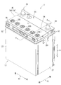
- FIG. 1 is a perspective view of a lead storage battery according to a first embodiment.
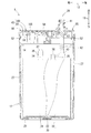
- Top view of battery case Vertical sectional view of the lead storage battery (AA sectional view in FIG. 1)
- Top view of top lid Bottom view of top lid
- FIG. 4 is an enlarged view of a part of FIG.
- FIG. 7 is an enlarged view of a part of FIG.
- Vertical sectional view of the top cover, filter, and passage opening / closing valve (BB sectional view in FIG. 9) Exploded view of filter and passage opening / closing valve
- Top view of cylindrical casing Perspective sectional view of a cylindrical casing
- Bottom view of top lid FIG. 15 is an enlarged view of a part of FIG.
- FIG. 14 is an enlarged view of a part of FIG. Plan view of the inner lid of the lead storage battery according to the third embodiment
- FIG. 14 is an enlarged view of a part of FIG. Vertical sectional view of the inner lid (BB sectional view in FIG. 4)
- the lead storage battery has an opening and a housing chamber that is continuous with the opening, a battery case in which a plurality of cell chambers that house the electrode group and the electrolyte solution are partitioned in the housing room, an exhaust port, and the opening is sealed.
- the exhaust passage has a plurality of individual passages that communicate with the cell chambers and a common passage that communicates with the individual passages and connects to the exhaust port. And a passage opening / closing valve arranged in the passage.
- the present inventors have studied to increase the ventilation resistance of the exhaust passage in order to suppress the decrease of the electrolyte.
- the ventilation resistance is increased, the amount of gas discharged to the outside through the exhaust passage decreases, and accordingly, the amount of water vapor and electrolyte mist discharged to the outside decreases.
- the gas passes through a filter of the collective exhaust unit as compared with a system in which each cell is individually exhausted.
- the amount of gas exhausted increases.
- the temperature of the lead storage battery decreases, the amount of gas sucked through the filter also increases.
- the amount of dust and the like entering the exhaust passage from the outside with the intake increases, so that the possibility that the filter is clogged increases.
- the filter is clogged in the centralized exhaust type lead-acid battery, the exhaust of the gas generated in the cell may be delayed, and the internal pressure of the cell may increase. Due to such a problem peculiar to the centralized exhaust system, it has been difficult to increase the ventilation resistance of the exhaust passage and to suppress the decrease of the electrolyte.
- the present inventor has come to realize that by arranging the passage opening / closing valve in the common passage, the ventilation resistance of the exhaust passage is increased. According to the lead storage battery, it is possible to increase the ventilation resistance of the exhaust passage to suppress the decrease in the electrolytic solution, and to reduce the pressure by the passage opening / closing valve when the internal pressure of the cell increases.
- the filter is arranged closer to the exhaust port than the passage opening / closing valve. Since the ventilation resistance is increased by the passage opening / closing valve, the humidity in the common passage is increased, and dew condensation is likely to occur. According to the above configuration, it is possible to prevent the droplets generated by the dew condensation from contacting the filter and clogging the filter.
- the passage opening / closing valve includes a tubular casing provided with a communication passage and a valve seat communicating with the common passage, and a plate-shaped valve main body disposed in the tubular casing and opening and closing the communication passage.
- the plate-shaped valve body is supported by the valve seat such that the posture can be changed between a posture in which the communication passage is closed by contacting the valve seat and a posture in which the communication passage is opened apart from the valve seat.
- the electrolyte even when the electrolyte flows from the battery case through the exhaust passage, the electrolyte contacts the plate-shaped valve body of the passage opening / closing valve, so that the electrolyte is prevented from reaching the filter. Thus, clogging of the filter and outflow of the electrolyte can be suppressed.
- the lead storage battery 1 is a liquid storage battery provided with a flowable electrolytic solution. As shown in FIGS. 1 to 3, the lead storage battery 1 includes a battery case 17, an electrode group 30, an electrolytic solution 14, terminals 38 and 39, and a cover member 45. Note that the vertical direction 11 is defined based on the use posture when the lead storage battery 1 is placed horizontally without inclination with respect to the installation surface.
- the lateral direction of the battery case 17, which is the direction in which the terminal portions 38 and 39 are arranged, is defined as the left-right direction 13, and the depth direction of the battery case 17 is defined as the front-rear direction 12.
- One of the front and rear directions 12 in which the terminal portions 38 and 39 are arranged is defined as a rear side.
- the battery case 17 includes four outer walls 27 and a bottom wall 28, and is a box-shaped member made of synthetic resin having an open upper surface.
- the battery case 17 has an opening 18 and a storage chamber 19 continuous with the opening 18.
- the battery case 17 includes five partition walls 29 arranged at equal intervals in the left-right direction 13.
- the partition 29 divides the housing chamber 19 of the battery case 17 into six cell chambers 21 to 26. That is, the six cell chambers 21 to 26 are formed in the accommodation room 19 of the battery case 17 in the left-right direction 13 in order from right to left by the partition wall 29.
- an electrolytic solution 14 made of dilute sulfuric acid and an electrode group 30 are accommodated.
- a plurality of cell chambers 21 to 26 containing the electrode group 30 and the electrolytic solution 14 are partitioned by the partition wall 29 and the outer wall 27 in the storage chamber 19.
- a plurality of cell chambers 21 to 26 are arranged in the accommodation room 19 side by side.
- the size of the cell chambers 21 to 25 in the front-rear direction 12 (longitudinal direction) is larger than the size in the left-right direction 13 (short direction).
- the size of the cell chambers 21 to 25 in the front-back direction 12 is preferably 2.5 times or more, and more preferably 6.3 times or less, the size in the left-right direction 13. As illustrated in FIG. 2, it is more preferable that the size of the cell chambers 21 to 25 in the front-rear direction 12 is 4.1 times the size of the left-right direction 13.
- the electrode group 30 includes a positive electrode plate 31, a negative electrode plate 32, and a separator 33, as shown in FIG.
- the separator 33 is disposed between the positive electrode plate 31 and the negative electrode plate 32, and separates the positive electrode plate 31 from the negative electrode plate 32.
- the positive electrode plate 31 and the negative electrode plate 32 are configured by filling a grid with an active material.
- the main component of the active material of the positive electrode plate 31 is lead dioxide, and the main component of the active material of the negative electrode plate 32 is lead.
- an ear portion 34 is provided on the upper portion of the positive electrode plate 31, and an ear portion 35 is provided on the upper portion of the negative electrode plate 32.
- the ear portion 34 is connected to the strap 36 for the positive electrode
- the ear portion 35 is connected to the strap 36 for the negative electrode.
- the strap 36 is a plate-shaped member extending in the left-right direction 13.
- the positive electrode plate 31 in the cell chamber is electrically connected by the strap 36 for the positive electrode
- the negative electrode plate 32 in the cell chamber is electrically connected by the strap 36 for the negative electrode.
- the positive and negative straps 36 of the adjacent cell chambers are electrically connected to each other via a connection portion 37 formed on the strap 36.
- the electrode groups 30 of the six cell chambers 21 to 26 are electrically connected in series.
- the lid member 45 includes an exhaust port 201, an inner lid 50 for closing the opening 18 of the battery case 17, and an upper lid 100 provided on the inner lid 50.
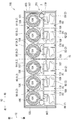
- FIG. 4 is a plan view of the inner lid 50 seen from above with the upper lid 100 removed
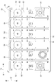
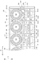
- FIG. 5 is a bottom view of the inner lid 50 seen from below.
- the inner lid 50 is made of a synthetic resin, and includes a lid plate 51 and a flange portion 52, as shown in FIGS.
- the exhaust port 201 is formed on the right side surface of the upper lid 100, as shown in FIG.
- the cover plate 51 is a member having a size capable of closing the opening above the battery case 17. As shown in FIG. 5, the lid plate 51 includes, on a lower surface thereof, a peripheral wall 53 formed along the flange portion 52 and a plurality of lid-side partition walls 54 formed so as to be continuous with the peripheral wall 53.
- the peripheral wall 53 protrudes downward from the lower surface of the cover plate 51.
- the peripheral wall 53 is formed in a substantially rectangular shape so as to correspond to the opening edge of the battery case 17.
- the lid-side partition wall 54 protrudes downward from the lower surface of the lid plate 51.
- Each lid-side partition 54 partitions the inside of the peripheral wall 53 so as to correspond to each partition 29 of the battery case 17. Then, the peripheral wall 53 is overlapped with the opening edge of the battery case 17, the lid-side partition wall 54 is overlapped with the partition wall 29 of the battery case 17, and these are joined by heat welding. Thereby, airtightness between the peripheral wall 53 and the battery case 17 and between the lid-side partition wall 54 and the partition wall 29 are ensured.
- the cover plate 51 includes a high surface portion 55 and a low surface portion 56.
- the high surface portion 55 is provided at the front and rear of the cover plate 51.
- a pair of terminal portions is disposed at both ends of the rear high surface portion 55 in the left-right direction 13. More specifically, the positive terminal portion 38 is disposed at the left end of the rear high surface portion 55, and the negative terminal portion 39 is disposed at the right end. Since the positive terminal section 38 and the negative terminal section 39 have substantially the same shape, the negative terminal section 39 will be described below as an example, and the description of the positive terminal section 38 will be omitted.
- the negative electrode terminal 39 includes a bushing 41 and a pole 42 as shown in FIG.
- the bushing 41 is made of a metal such as a lead alloy, and is a hollow cylindrical member. As shown in FIG. 3, the bushing 41 is mounted on a cylindrical mounting portion 67 formed on the high surface portion 55. The bushing 41 penetrates the mounting portion 67, and the upper portion of the bushing 41 projects from the upper surface of the high surface portion 55. A portion of the bushing 41 protruding from the high surface portion 55 is a terminal connection portion, to which a connection terminal (not shown) such as a harness terminal is attached.
- the pole 42 is a metal member such as a lead alloy and has a cylindrical shape.
- the pole 42 is located inside the bushing 41.
- the pole 42 is longer than the bushing 41, and the upper part of the pole 42 is located inside the bushing 41, and the lower part of the pole 42 projects downward from the lower surface of the bushing 41.
- the upper end (tip) of the pole 42 is joined to the bushing 41 by welding, and the base 43 of the pole 42 is joined to the strap 36 of the electrode group 30.
- the lower surface portion 56 of the inner lid 50 is formed closer to the front of the lid plate 51.
- the low surface portion 56 is provided to extend in the left-right direction 13 across the six cell chambers 21 to 26 provided in the battery case 17.
- the upper surface of the low surface portion 56 is located lower than the upper surface of the high surface portion 55.
- the upper surface wall 57 of the lower surface portion 56 of the inner lid 50 has six liquid injection holes 68 arranged in the left-right direction 13. These six liquid injection holes 68 penetrate the upper surface wall 57 of the lower surface portion 56 in the up-down direction 11 and communicate with the six cell chambers 21 to 26, respectively.
- the lower surface portion 56 includes a lower cylindrical wall 69, a lower outer peripheral wall 70, and a lower partition wall 71 protruding upward from the upper surface of the upper wall 57.
- the lower cylinder wall 69 is a cylindrical partition surrounding the liquid injection hole 68, and is provided in each of the six liquid injection holes 68.
- the lower outer peripheral wall 70 is a substantially rectangular partition wall provided along the outer edge of the low surface portion 56 and surrounding the low surface portion 56.
- the lower partition 71 is a partition extending forward from the lower outer peripheral wall 70 at the rear, and is provided corresponding to each partition 29 of the battery case 17.
- the upper lid 100 is made of a synthetic resin.
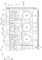
- FIG. 6 is a plan view of the upper lid 100 as viewed from above
- FIG. 7 is a bottom view of the upper lid 100 as viewed from below.
- the upper lid 100 includes a lid main body 101 and a flange portion 103, as shown in FIGS.
- the lid body 101 is a rectangular member that follows the lower surface portion 56 of the inner lid 50, and is attached to the lower surface portion 56 of the inner lid 50 in an overlapping manner.
- the flange portion 103 is formed on the left and right outer peripheral edges of the lid main body 101.
- the flange portion 103 protrudes downward from the lid body 101 and is located outside the left and right ends of the low surface portion 56 of the inner lid 50.
- the upper surface wall 102 of the lid main body 101 has six liquid injection holes 104 arranged in the left-right direction 13. These six liquid injection holes 104 are formed at positions corresponding to the liquid injection holes 68 of the inner lid 50, penetrate the upper wall 102 of the lid main body 101 in the vertical direction 11, and are connected to the six cell chambers 21 to 26. Each is in communication.
- the electrolyte 14 is injected into each of the cell chambers 21 to 26 of the battery case 17 through the respective injection holes 104 and the respective injection holes 68.
- a liquid port plug 105 is attached to each liquid injection hole 104, and the liquid injection hole 104 is closed.
- the lid main body 101 includes an upper cylindrical wall 106, an upper outer peripheral wall 107, and an upper partition 108 that project downward from the lower surface of the upper wall 102.
- the upper cylindrical wall 106 is a cylindrical partition surrounding the liquid injection hole 104, and is provided in each of the six liquid injection holes 104.
- the upper outer peripheral wall 107 is a substantially rectangular partition wall provided inside the flange portion 103 along the outer edge of the lid main body 101.
- the upper partition 108 is a partition extending forward from the rear upper outer peripheral wall 107, and is provided corresponding to each partition 29 of the battery case 17.
- Each upper cylindrical wall 106 corresponds to each lower cylindrical wall 69.
- each upper cylindrical wall 106 is disposed so as to overlap above each lower cylindrical wall 69.
- Each upper cylinder wall 106 and each lower cylinder wall 69 are joined by heat welding, and airtightness between each upper cylinder wall 106 and each lower cylinder wall 69 is ensured.
- the upper outer peripheral wall 107 corresponds to the lower outer peripheral wall.
- the upper outer peripheral wall 107 is disposed so as to overlap above the lower outer peripheral wall 70.
- the upper outer peripheral wall 107 and the lower outer peripheral wall 70 are joined by heat welding, and airtightness between the upper outer peripheral wall 107 and the lower outer peripheral wall 70 is secured.
- Each upper partition 108 corresponds to each lower partition 71.
- each upper partition 108 is disposed so as to overlap above each lower partition 71.
- Each upper partition 108 and each lower partition 71 are joined by heat welding, and the airtightness between each upper partition 108 and each lower partition 71 is ensured.
- the lid member 45 includes the exhaust passage 2 between the inner lid 50 and the upper lid 100.
- the exhaust passage 2 is a passage connecting the storage chamber 19 of the battery case 17 and the exhaust port 201 provided in the cover member 45.
- the exhaust passage 2 is a passage for guiding gas generated in the cell chambers 21 to 26 of the battery case 17 to the exhaust port 201 and discharging the gas to the outside of the lead storage battery 1.
- the exhaust passage 2 includes a plurality of individual passages 81 to 86 and a common passage 9.
- the lid member 45 includes six individual passages 81 to 86.
- the individual passages 81 to 86 communicate with the six cell chambers 21 to 26, respectively.
- the common passage 9 is a passage that communicates with the individual passages 81 to 86 and is connected to the exhaust port 201.
- the common passage 9 includes seven passages 91 to 97.
- the individual passage 81 and the passage 91 and the individual passage 86 and the passage 96 are formed by a plane 15 whose normal line is parallel to the left-right direction 13 and passes through the center of the lid member 45 in the left-right direction 13.
- the individual passages 82 and 92 and the individual passages 85 and 95 have shapes symmetric with respect to the plane 15.
- the individual passages 83 and 93 and the individual passages 84 and 94 have shapes symmetric with respect to the plane 15.
- the individual passages 82 and 92 and the individual passages 83 and 93 have substantially the same shape.
- the individual passages 81 to 86 are provided between the inner lid 50 and the upper lid 100 for each of the cell chambers 21 to 26 of the battery case 17.
- the individual passages 81 to 86 communicate with the common passage 9 and have a function of flowing gas flowing out of the cell chambers 21 to 26 to the common passage 9.
- Each of the individual passages 81 to 86 includes an exhaust portion 6 provided at an end on the cell chamber side, and a passage formed by lower passage walls 61 to 66 and upper passage walls 111 to 116 described later.
- the exhaust part 6 is substantially cylindrical and has a gas passage inside.
- the lower surface portion 56 of the inner lid 50 includes six lower cylindrical portions 78 arranged in the left-right direction 13.
- the lower cylindrical portion 78 has a rectangular cylindrical shape, and has a part of the lower outer peripheral wall 70, a part of the lower partition 71, and two lower peripheral walls 72, 73.
- the two lower peripheral walls 72 and 73 project upward from the upper surface of the upper surface wall 57 of the low surface portion 56.
- the upper surface wall 57 of the low surface portion 56 includes six communication holes 74 arranged in the left-right direction 13. Each communication hole 74 is located inside each lower cylindrical portion 78. Each communication hole 74 penetrates the upper surface wall 57 of the lower surface portion 56 in the vertical direction 11 and communicates with each of the cell chambers 21 to 26 of the battery case 17.
- the lid main body 101 of the upper lid 100 includes six upper cylindrical portions 118 arranged in the left-right direction 13 as shown in FIG. As shown in FIGS. 7 and 9, the upper cylindrical portion 118 has a rectangular cylindrical shape, and includes a part of the upper outer peripheral wall 107, a part of the upper partition 108, and two upper peripheral walls 109 and 110. Have been. The two upper peripheral walls 109 and 110 project downward from the lower surface of the upper surface wall 102 of the lid main body 101.
- Each lower cylinder portion 78 and each upper cylinder portion 118 vertically overlap to constitute one exhaust unit 6.
- the upper peripheral wall 109 corresponds to the lower peripheral wall 72, and overlaps the corresponding lower peripheral wall 72 and is joined by heat welding.
- the upper peripheral wall 110 does not overlap with the lower peripheral wall 73 and is located to the right of the lower peripheral wall 73 (in the right end exhaust portion 6, the upper peripheral wall 110 is larger than the lower peripheral wall 73. To the left).
- the upper outer peripheral wall 107 and the upper partition 108 overlap the corresponding lower outer peripheral wall 70 and the lower partition 71, and are joined by thermal welding.
- Each exhaust unit 6 configured as described above communicates with each of the cell chambers 21 to 26 through each communication hole 74. Therefore, the gas generated in each of the cell chambers 21 to 26 of the battery case 17 flows into each of the exhaust portions 6 through the communication holes 74, and flows into the upper peripheral wall 110 and the lower peripheral wall 73 separated in the left-right direction 13. And flows toward the exhaust port 201 through the individual passages 81 to 86.
- the lower surface portion 56 of the inner lid 50 has a plurality of lower passage walls 61 to 66 for each of the cell chambers 21 to 26 of the battery case 17.
- the lower passage walls 61 to 66 project upward from the upper surface of the upper surface wall 57 of the lower surface portion 56.
- the lower passage wall 61 is a wall extending leftward from the lower peripheral wall 72 of the lower cylindrical portion 78 and is formed continuously with the lower peripheral wall 72.
- the left end of the lower passage wall 61 is bent obliquely right and rearward in the vicinity of the lower partition wall 71 and extends to the vicinity of the lower outer peripheral wall 70.
- the lower passage wall 62 is a wall protruding from the lower partition wall 71 and extending obliquely rightward and rearward.
- the right end of the lower passage wall 62 is bent rearward in the vicinity of the lower passage wall 65 and extends to the vicinity of the lower passage wall 61.
- the lower passage wall 63 is a wall protruding from the lower passage wall 62 and extending rearward, and its tip is located near the lower passage wall 61.
- the lower passage wall 64 is a wall that protrudes from the lower partition wall 71 and extends leftward, and extends partway diagonally leftward and rearward.
- the distal end of the lower passage wall 64 is bent rearward near the left lower partition wall 71 and extends to the vicinity of the lower passage wall 62.
- the lower passage wall 65 is a wall that protrudes from the lower passage wall 64 and extends rearward, and its tip is located near the lower passage wall 61.
- the lower passage wall 66 is a wall protruding from the lower partition wall 71 and extending rightward, and its tip is located near the right lower partition wall 71.
- the lower passage walls 61 to 66 described above are aggregates of walls having different directions, as shown in FIG. As described above, the lower passage walls 61 to 66 are connected to the other lower passage walls 61 to 66 and the lower partition 71, and these walls have a bent shape. Thus, the paths of the individual passages 81 to 86 have a non-linear maze shape. That is, the lid member 45 has lower passage walls 61 to 66 that bend the individual passages 81 to 86.
- the lower passage walls 61 to 66 are examples of passage walls.
- the lid main body 101 of the upper lid 100 has a plurality of upper passage walls 111 to 116 for each of the cell chambers 21 to 26 of the battery case 17.
- the upper passage walls 111 to 116 protrude downward from the lower surface of the upper wall 102 of the lid main body 101.
- the upper passage wall 111 is a wall that extends the upper peripheral wall 109 of the upper cylindrical portion 118 to the left, and is formed continuously with the upper peripheral wall 109.
- the left end of the upper passage wall 111 is bent obliquely rightward and rearward in the vicinity of the upper partition 108 and extends to the vicinity of the upper outer peripheral wall 107.
- the upper passage wall 112 is a wall protruding from the upper partition wall 108 and extending obliquely rightward and rearward.
- the right end of the upper passage wall 112 is bent rearward in the vicinity of the upper passage wall 115 and extends to the vicinity of the upper passage wall 111.
- the upper passage wall 113 is a wall that protrudes from the upper passage wall 112 and extends rearward, and its tip is located near the upper passage wall 111.
- the upper passage wall 114 is a wall that protrudes from the upper partition 108 and extends leftward, and extends obliquely leftward and backward from the middle.
- the distal end of the upper passage wall 114 is bent rearward in the vicinity of the left upper partition wall 108 and extends to the vicinity of the upper passage wall 112.
- the upper passage wall 115 is a wall that protrudes from the upper passage wall 114 and extends rearward, and its tip is located near the upper passage wall 111.
- the upper passage wall 116 is a wall protruding from the upper partition 108 and extending rightward, and its tip is located near the right upper partition 108.
- the above-described upper passage walls 111 to 116 are aggregates of walls having different directions, as shown in FIG. As described above, the upper passage walls 111 to 116 are connected to the other upper passage walls 111 to 116 and the upper partition 108, and these walls have a bent shape. Thus, the paths of the individual passages 81 to 86 have a non-linear maze shape. That is, the lid member 45 has upper passage walls 111 to 116 that bend the individual passages 81 to 86.
- the upper passage walls 111 to 116 are examples of passage walls.
- the upper passage walls 111 to 116 and the lower passage walls 61 to 66 are vertically overlapped to form a passage wall.
- the upper passage walls 111 to 116 correspond to the lower passage walls 61 to 66, overlap the corresponding lower passage walls 61 to 66, and are joined by heat welding.
- the individual passages 81 to 86 are provided between the thus formed passage wall, the lower partition wall 71, the upper partition wall 108, the lower outer peripheral wall 70, and the upper outer peripheral wall 107.
- the paths of the individual passages 82 and 83 start from the communication hole 74 to the left between the lower passage wall 61 and the lower outer peripheral wall 70, and pass through the lower passage wall 61. Proceed downward between the lower partition 71. Next, the route travels rightward between the lower passage wall 61 and the lower passage wall 62 and travels downward between the lower passage wall 62 and the lower passage wall 65. Next, the route proceeds to the left between the lower passage wall 62 and the lower passage wall 64, and proceeds downward between the lower passage wall 64 and the lower partition wall 71. Then, the route proceeds rightward between the lower passage wall 64 and the lower passage wall 66, and ends at a gap between the lower passage wall 66 and the lower partition wall 71. At the end point, the individual passages 82 and 83 merge into the common passage 9.
- the path of the individual passage 81 starts from the communication hole 74 and proceeds rightward between the lower passage wall 61 and the lower outer peripheral wall 70, and the lower passage wall 61 and the lower It travels downward between the outer peripheral wall 70.
- the route proceeds to the left between the lower passage wall 61 and the lower passage wall 62 and proceeds downward between the lower passage wall 62 and the lower passage wall 65.
- the route proceeds rightward between the lower passage wall 62 and the lower passage wall 64 and proceeds downward between the lower passage wall 64 and the lower tubular portion 79.
- the route ends at the gap between the lower passage wall 64 and the lower tubular portion 79.
- the individual passage 81 joins the common passage 9.
- the common passage 9 is provided between the inner lid 50 and the upper lid 100.
- the common passage 9 communicates with each of the individual passages 81 to 86 and connects to the exhaust port 201.
- the common passage 9 collects gas flowing from the six individual passages 81 to 86 and discharges the gas from the exhaust port 201 to the outside of the lead storage battery 1.
- the common passage 9 is constituted by seven passages 91 to 97.
- a collective exhaust unit 3 is provided at the end of the passage 97 on the exhaust port 201 side.
- the collective exhaust unit 3 is provided between the inner lid 50 and the upper lid 100, and has a function of collectively exhausting gas generated in the cell chambers 21 to 26 to the outside of the lead storage battery 1.
- the collective exhaust unit 3 is disposed at the right end of the cover member 45, as shown in FIG.
- the collective exhaust unit 3 may be arranged at another position, for example, at the left end of the lid member 45.
- the lower surface portion 56 of the inner lid 50 includes a lower tubular portion 79.
- the lower cylindrical portion 79 protrudes upward from the upper surface of the upper surface wall 57 of the lower surface portion 56.
- the lower cylinder portion 79 is connected to a lower cylinder wall 69 and a lower outer peripheral wall 70 at the right end.
- the lid main body 101 of the upper lid 100 includes an upper cylindrical portion 119 and an exhaust duct 200.
- the upper cylindrical portion 119 protrudes downward from the lower surface of the upper wall 102 of the lid main body 101.
- the upper cylinder portion 119 is connected to the upper cylinder wall 106 and the upper outer peripheral wall 107 at the right end.
- the left end portion of the exhaust duct 200 is connected to a space inside the upper cylindrical portion 119.
- the right end of the exhaust duct 200 is connected to an exhaust port 201 formed on the right side surface of the upper lid 100.
- a filter 331 and a passage opening / closing valve 332 are housed in a space inside the upper cylindrical portion 119.
- the filter 331 prevents the external spark from entering the inside of the lead storage battery 1.
- the filter 331 is a disk-shaped member, and is, for example, a porous body having continuous holes.
- the porous body is, for example, a sintered body of ceramic particles such as alumina or resin particles such as polypropylene.
- the filter 331 has, for example, an average diameter of several tens to several hundred ⁇ m.
- the passage opening / closing valve 332 includes a tubular casing 334 in which a communication passage 335 communicating with the common passage 9 and a valve seat 337 are formed, and a plate-shaped valve main body 333 disposed in the tubular casing 334 and opening and closing the communication passage 335.
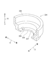
- the plate-shaped valve body 333 is a disk-shaped member as shown in FIG.
- the plate-shaped valve body 333 is made of, for example, a synthetic resin such as a polypropylene resin, a polyethylene resin, or a copolymer thereof.
- the cylindrical casing 334 is a substantially cylindrical casing as shown in FIGS.
- the cylindrical casing 334 is made of, for example, a synthetic resin such as a polypropylene resin, a polyethylene resin, or a copolymer thereof.
- the cylindrical casing 334 includes a cylindrical peripheral wall 336 and a valve seat 337 connected to a lower end of the peripheral wall 336.
- the valve seat 337 includes a through hole 338 that passes through the valve seat 337 in the up-down direction 11 and three protrusions 339 that protrude upward from the upper surface of the valve seat 337.
- the protrusion 339 is arranged around the through hole 338.
- a communication path 335 is formed by the space inside the cylindrical peripheral wall 336 and the through hole 338.
- the plate-shaped valve main body 333 is placed on the upper surface of the valve seat 337 in a state of covering the through hole 338.
- the plate-shaped valve main body 333 is vertically movable in the communication passage 335.
- the pressure in the cell chamber is low, the plate-shaped valve body 333 contacts the valve seat 337 and covers the through hole 338. In this state, the communication path 335 is closed.
- the pressure in the cell chamber increases, all or a part of the plate-shaped valve body 333 is separated from the valve seat 337, all or a part of the through hole 338 is opened, and the communication path 335 is opened.
- the plate-shaped valve main body 333 is configured so that the posture can be changed between a first posture in which the communication passage 335 is closed by contacting the valve seat 337 and a second posture in which the communication passage 335 is opened apart from the valve seat 337. It is supported by a seat 337.
- the plate-shaped valve body 333 contacts the valve seat 337 and the communication passage 335 is closed (first posture), the plate-shaped valve body is A gap 340 exists between 333 and valve seat 337. Due to the gap 340, the passage opening / closing valve 332 is an incomplete check valve, and the lead storage battery 1 is configured so that the pressure inside the exhaust passage 2 and the inside of the cell chambers 21 to 25 does not become lower than the atmospheric pressure. ing.
- the passage opening / closing valve 332 is a complete check valve, that is, when the plate-shaped valve body 333 is in contact with the valve seat 337 and the communication passage 335 is closed, the gap 340 does not exist and the gas flows.
- the presence of the gap 340 suppresses a decrease in the internal pressure of the battery case 17 when the temperature of the lead storage battery 1 decreases, suppresses a rise in the level of the electrolyte 14, and suppresses the increase in the electrolyte 14. Is suppressed.
- the filter 331 is inserted into the upper part of the peripheral wall 336 of the cylindrical casing 334. That is, the filter 331 is located above the plate-shaped valve main body 333. As described above, in the present embodiment, the filter 331 and the passage opening / closing valve 332 are integrated. Then, the integrated filter 331 and the passage opening / closing valve 332 are accommodated in a space inside the upper cylindrical portion 119, as shown in FIG.
- the upper cylinder part 119 and the lower cylinder part 79 are vertically welded and overlapped with each other to form the collective exhaust unit 3. That is, the integrated filter 331 and the passage opening / closing valve 332 are housed inside the collective exhaust unit 3 as shown in FIG.
- the filter 331 is disposed on the exhaust port 201 side of the common passage 9.
- the passage opening / closing valve 332 is disposed on the side opposite to the exhaust port 201 with respect to the filter 331.
- the passage opening / closing valve 332 is arranged in the common passage 9 on the side where the cell chambers 21 to 26 are located as viewed from the filter 331.
- the filter 331 is disposed closer to the exhaust port 201 than the passage opening / closing valve 332.
- the communication passage 335 of the passage opening / closing valve 332 communicates with the space inside the upper cylindrical portion 119 via the filter 331.
- the communication passage 335 communicates with the space inside the upper cylindrical portion 119 via the through hole 338. That is, the communication passage 335 communicates with the passage 97 of the common passage 9.
- the gas from the passage 97 flows into the space inside the lower cylinder portion 79 from the opening in front of the lower cylinder portion 79, and passes through the passage opening / closing valve 332 and the filter 331.
- the gas that has passed through the filter 331 flows into the exhaust duct 200 from the space above the upper cylindrical portion 119, and is discharged to the outside of the lead storage battery 1 through the exhaust port 201.
- the passages 91 to 97 include a lower connecting wall 76, an upper connecting wall 117, the above-described lower cylindrical wall 69, lower outer peripheral wall 70, lower partition 71, lower cylindrical portion 79, upper cylindrical wall 106, It is formed by the outer peripheral wall 107, the upper partition 108, and the upper cylindrical portion 119.
- the lower surface portion 56 of the inner lid 50 includes a lower connecting wall 76.
- the lower connecting wall 76 protrudes upward from the upper surface of the upper surface wall 57 of the low surface portion 56.
- the lower connection wall 76 is connected to the right lower cylinder wall 69, the left lower cylinder wall 69, and the lower partition wall 71.
- the lid main body 101 of the upper lid 100 includes an upper connecting wall 117.
- the upper connecting wall 117 protrudes downward from the lower surface of the upper wall 102 of the lid main body 101.
- the upper connection wall 117 is connected to the right upper cylinder wall 106 and the left upper cylinder wall 106.
- the upper connecting wall 117 and the lower connecting wall 76 are vertically overlapped to form a passage wall. More specifically, the upper connecting wall 117 corresponds to the lower connecting wall 76, and overlaps the corresponding lower connecting wall 76 and is joined by heat welding.
- the passage wall thus formed, the lower cylindrical wall 69, the lower outer peripheral wall 70, the lower partition 71, the lower cylindrical portion 79, the upper cylindrical wall 106, the upper outer peripheral wall 107, the upper partition 108, and the upper cylinder Passages 91 to 97 are provided between the portions 119.
- the path of the passage 91 starts from the end point of the individual passage 81 (the gap between the upper passage wall 114 and the upper cylinder part 119), and starts from the upper cylinder part 119 and the upper cylinder wall 106 and the upper passage.
- the vehicle travels diagonally left and forward between the wall 114 and the upper partition 108.
- the path passes through the gap between the upper partition wall 108 and the upper connecting wall 117, proceeds downward between the upper partition wall 108 and the upper cylindrical wall 106, and proceeds to the end point of the individual passage 82 (the upper passage wall 116 and the upper
- the gap between the partition wall 108 and the partition wall 108 is defined as the end point.
- the path of the passage 92 starts from the end point (the gap between the upper passage wall 116 and the upper partition 108) of the individual passage 82 and the passage 91 and starts from the upper passage wall 116, the upper partition 108, and the upper cylinder. Proceed to the left between wall 106. Next, the path passes through the gap between the upper partition wall 108 and the upper connecting wall 117, passes downward between the upper partition wall 108 and the upper cylindrical wall 106, and proceeds downward to the end point of the individual passage 83 (the upper passage wall 116 and the upper The gap between the partition wall 108 and the partition wall 108 is defined as the end point.
- the path of the passage 93 starts from the end point (the gap between the upper passage wall 116 and the upper partition 108) of the individual passage 83 and the passage 92, and starts from the upper passage wall 116 and the upper cylindrical wall 106. Go to the left. Next, the route proceeds diagonally forward left between the upper partition 108 and the upper cylindrical wall 106, and ends at a gap between the upper partition 108 and the upper outer peripheral wall 107.
- the path of the passage 97 starts from the end point of the passage 93 (the gap between the upper partition wall 108 and the upper outer peripheral wall 107), and the upper cylindrical wall 106, the upper connecting wall 117, and the upper outer peripheral wall 107. To the right and then to the rear, with the collective exhaust unit 3 as the end point.
- the gas generated in the cell chamber 21 located at the right end in the left-right direction 13 is exhausted through the individual passage 81, the passage 91, the passage 92, the passage 93, the passage 97, and the collective exhaust unit 3. It is discharged from the port 201 to the outside of the lead storage battery 1.
- the gas generated in the cell chamber 22 located adjacent to the left of the cell chamber 21 passes through the individual passage 82, the passage 92, the passage 93, the passage 97, and the collective exhaust unit 3, and passes through the exhaust port 201. It is discharged to the outside of the lead storage battery 1.
- the gas generated in the cell chamber 23 located adjacent to the left of the cell chamber 22 passes through the individual passage 83, the passage 93, the passage 97, and the collective exhaust unit 3, and passes from the exhaust port 201 to the lead storage battery 1. It is discharged outside.
- the passage length of the cell chamber 21 is the sum of the lengths of the individual passage 81, the passage 91, the passage 92, the passage 93, and the passage 97.
- the passage length of the cell chamber 22 is the sum of the lengths of the individual passage 82, the passage 92, the passage 93, and the passage 97. Accordingly, the passage length of the cell chamber 21 is longer than the passage length of the cell chamber 22.
- the passage length of the cell chamber 23 is the total length of the individual passages 83, the passages 93, and the passages 97. Therefore, the passage length of the cell chamber 22 is longer than the passage length of the cell chamber 23.
- the gas generated in the cell chamber 26 located at the left end in the left-right direction 13 is exhausted through the individual passage 86, the passage 96, the passage 95, the passage 94, the passage 97, and the collective exhaust unit 3. It is discharged from the port 201 to the outside of the lead storage battery 1.
- Gas generated in the cell chamber 25 located adjacent to the right of the cell chamber 26 passes through the individual passage 85, the passage 95, the passage 94, the passage 97, and the collective exhaust unit 3, and passes through the exhaust port 201. It is discharged to the outside of the lead storage battery 1.
- the gas generated in the cell chamber 24 located adjacent to the right of the cell chamber 25 passes through the individual passage 84, the passage 94, the passage 97, and the collective exhaust unit 3, and passes through the exhaust port 201 to the lead storage battery 1. It is discharged outside.
- the length (passage length) of the exhaust passage 2 from the cell chambers 24 to 26 to the collective exhaust unit 3 is compared.
- the passage length of the cell chamber 26 is the sum of the lengths of the individual passage 86, the passage 96, the passage 95, the passage 94, and the passage 97.
- the passage length of the cell chamber 25 is the sum of the lengths of the individual passage 85, the passage 95, the passage 94, and the passage 97. Therefore, the passage length of the cell chamber 26 is longer than the passage length of the cell chamber 25.
- the passage length of the cell chamber 24 is the sum of the lengths of the individual passages 84, the passages 94, and the passages 97. Therefore, the passage length of the cell chamber 25 is longer than the passage length of the cell chamber 24.
- the length of the exhaust passage 2 from the cell chamber 21 and the cell chamber 26 located at the end in the left-right direction 13 to the collective exhaust unit 3 is equal to the remaining cell chambers 22, 23, 24, and It is longer than the length of the exhaust passage 2 from 25 to the collective exhaust portion 3 (passage opening / closing valve 332).
- the lower surface portion 56 of the inner lid 50 includes six return holes 77 arranged in the left-right direction 13. As shown in FIG. 8, each return hole 77 is located in a region surrounded by a lower outer peripheral wall 70, a lower partition 71, a lower peripheral wall 73, and a lower passage wall 61. Each return hole 77 penetrates the upper wall 57 of the lower surface portion 56 in the up-down direction 11 and communicates with each of the cell chambers 21 to 26 of the battery case 17. In the present embodiment, as shown in FIGS. 4 and 5, the return hole 77 is disposed at the center of each of the cell chambers 21 to 26 of the battery case 17 as viewed in the up-down direction 11.
- the return hole 77 is arranged at the center of each of the cell chambers 21 to 26 of the battery case 17. Thus, even if the lead storage battery 1 falls in any of the left, right, front, and rear directions, the outflow of the electrolyte 14 from the return hole 77 is suppressed.
- the upper surface of the upper surface wall 57 of the low surface portion 56 which is the bottom surface of the individual passages 81 to 86, is inclined so as to be lower in the vertical direction 11 as being closer to the return hole 77.
- water droplets due to water vapor contained in the gas from the cell chambers 21 to 26 and liquid droplets such as an electrolytic solution can be returned to the cell chambers 21 to 26 through the return hole 77. That is, water vapor contained in the gas generated in the cell chambers 21 to 26 is condensed in the individual passages 81 to 86 when the gas passes through the individual passages 81 to 86.
- the condensed droplet flows toward the return hole 77 due to the inclination of the upper surface of the upper surface wall 57. Therefore, droplets such as water vapor contained in the gas can be returned to each of the cell chambers 21 to 26.
- Examples and comparative examples 1 to 4 described below are examples and comparative examples of the lead-acid battery 1 described in the first detailed description column. Test results for the examples and comparative examples 1 to 4 are as follows. In Tables 1 and 2. The following Examples and Comparative Examples 1 to 4 were evaluated for the easiness of clogging, measured for airflow resistance, evaluated for reducing the amount of liquid, and evaluated for increasing the internal pressure. The result was obtained. Further, a test for evaluating the amount of decrease in the liquid level in each cell chamber was performed on the examples and comparative example 1, and the results shown in Table 2 were obtained.
- a filter having a standard fineness is used as the filter 331.
- the passage opening / closing valve 332 and the remaining configuration are the same as those in the above embodiment.
- Comparative Example 1 uses the same filter as the example as the filter 331, and does not include the passage opening / closing valve 332. Other configurations are the same as those of the embodiment.
- Comparative Example 2 uses a filter finer than the filters of Example and Comparative Example 1 as the filter 331, and does not include the passage opening / closing valve 332. Other configurations are the same as those of the embodiment.
- Comparative Example 3 uses a filter having a finer size than the filter of Comparative Example 2 as the filter 331, and does not include the passage opening / closing valve 332. Other configurations are the same as those of the embodiment.
- Comparative Example 4 uses a filter with a finer size than the filter of Comparative Example 3 as the filter 331 and does not include the passage opening / closing valve 332. Other configurations are the same as those of the embodiment.
- the ventilation resistance of the filter and the passage opening / closing valve was measured as follows.
- the filter is placed inside the cylinder, air is supplied from one opening of the cylinder at a flow rate of 1 liter / min, and the pressure of the air before passing through the filter is measured.
- the value obtained by subtracting the atmospheric pressure from the measured pressure is defined as the ventilation resistance of the filter.
- both the filter and the passage opening / closing valve were arranged inside the cylinder and measured.
- the example was 0.6 kPa
- the comparative example 1 was 0.3 kPa
- the comparative example 2 was 0.6 kPa
- the comparative example 3 was 1.2 kPa
- the comparative example 4 was 1.8 kPa.
- the lead storage battery 1 is placed in an environment of 60 ° C., and a vertical vibration is applied while charging at a constant voltage of 13.8 V. The frequency of the vibration is swept from 10 Hz to 55 Hz, and the acceleration is 9.8 m / s 2 .
- the test time is 120 hours. The difference between the weight of the lead storage battery 1 before the start of the test and the weight of the lead storage battery 1 after the end of the test is divided by the test time (120 hours) to determine the amount of liquid reduction [g / h] per unit time. .
- An evaluation test of the increase in internal pressure was performed as follows. A through-hole in the up-down direction 11 is provided in the lid member 45, a predetermined flow rate of air is supplied to the cell chamber 23 through the through-hole, and the internal pressure of the cell chamber 23 is measured. If the internal pressure of the cell chamber 23 is equal to or lower than a predetermined reference value, the test is passed. If the internal pressure is higher than the reference value, the test is failed. As a result, Examples and Comparative Examples 1 and 2 passed, and Comparative Examples 3 and 4 failed.
- a test for evaluating the amount of decrease in the liquid level in each cell chamber was performed as follows.
- the lead storage battery 1 was mounted on the vehicle, and the vehicle was run in a predetermined running pattern. Based on the liquid level before the start of the test, the amount of decrease in the liquid level at the end of the test was measured.
- the running pattern the engine is stopped for 12 hours after repeating running at a speed of 60 km / h for 2 hours and idling for 2 hours three times. This pattern is repeated 40 times.
- the lead storage battery 1 is arranged on the right side of the engine when the vehicle is viewed from the front with the front surface facing the front of the vehicle.
- the cell chamber 26 is arranged at a position closest to the engine.
- the amount of decrease in the liquid level of the example was smaller than that of the comparative example 1 in all the cell chambers 21 to 26.
- the total liquid reduction amount of the example (the total amount of reduction in the liquid level) was 91% of the total liquid reduction amount of Comparative Example 1.
- the variation width of the liquid level in the example (the difference between the maximum value and the minimum value of the reduction amount of the liquid level) was 0.4 mm smaller than that of Comparative Example 1.
- the difference in configuration between the lead storage battery 1 of the embodiment and the lead storage battery 1 of the comparative example 1 is only the presence or absence of a passage opening / closing valve. Therefore, when the lead storage battery 1 is provided with the passage opening / closing valve, not only the amount of reduction of the electrolytic solution is reduced, but also the unexpected effect of reducing the variation in the amount of reduction of the cell chambers 21 to 26 is produced.
- the lead storage battery 1 provided with the passage opening / closing valve can reduce the reduction amount of the electrolyte and the variation of the reduction amount between the plurality of cell chambers.
- the filter was easily clogged, and the test for increasing the internal pressure also failed. Therefore, it is preferable to suppress the decrease of the electrolytic solution by using the passage opening / closing valve as in the embodiment.
- the filter 331 is inserted into the cylindrical casing 334 and the filter 331 and the passage opening / closing valve 332 are integrated has been described. It may be located remotely.
- a gap is generated between the plate-shaped valve main body 333 and the valve seat 337.
- the gas generated in the cell chambers 21 to 26 and passed through the exhaust passage 2 reaches the filter 331 through a gap generated between the plate-shaped valve main body 333 and the valve seat 337.
- the gap 340 is formed by the valve seat 337 of the cylindrical casing 334 having the projection 339 .
- a projection may be provided on the lower surface of the plate-shaped valve main body 333.
- the gap 340 may be formed by providing a groove in the valve seat 337 or the plate-shaped valve main body 333 instead of the protrusion.
- the filter 331 is disposed closer to the exhaust port 201 than the passage opening / closing valve 332 in the common passage 9.
- the filter 331 is disposed closer to the battery case 17 than the passage opening / closing valve 332. May be done.
- the passage opening / closing valve 332 may be disposed closer to the exhaust port 201 than the filter 331.
- a battery case having an opening and a housing chamber that is continuous with the opening, and a plurality of cell chambers that house the electrode group and the electrolyte solution in the housing room, An exhaust port, an inner lid that seals the opening, an upper lid provided in the inner lid, an exhaust passage formed between the inner lid and the upper lid, and connecting the storage chamber and the exhaust port, And a lid member having The exhaust passage has a plurality of individual passages communicating with the respective cell chambers and a common passage communicating with the individual passages and connecting to the exhaust port, A filter disposed in the common passage; And a passage opening / closing valve disposed in the common passage.
- the passage opening / closing valve is A tubular casing formed with a communication passage and a valve seat communicating with the common passage, A plate-shaped valve main body that is arranged in the cylindrical casing and opens and closes the communication path, The plate-shaped valve body is supported by the valve seat such that the posture can be changed between a posture in which the communication passage is closed by contacting the valve seat and a posture in which the communication passage is opened apart from the valve seat.
- the lead-acid battery according to (2).
- the present lead-acid battery has an opening, a battery case in which a cell chamber containing an electrode group and an electrolytic solution is connected to the opening and is partitioned by a long wall and a short wall, and a liquid port or a reflux hole communicating with the cell chamber.
- the present inventors have studied the shapes of the wells (cylindrical members) and the slits in order to suppress the external leakage of the electrolyte.
- the slit of the well is arranged such that the angle ⁇ at which the imaginary line passing through the center of the slit from the center of the liquid port or the reflux hole intersects the imaginary plane including the longitudinal wall is 90 ° (Patent Document 1 and 2 (hereinafter referred to as “short-side arrangement”), or an arrangement in which the imaginary line is parallel to the imaginary plane (the arrangement of Patent Document 3, hereinafter referred to as “long-side arrangement”).
- Vibration overflowing property that is, the difficulty of electrolyte overflow when vibration is applied to a lead storage battery is evaluated by a vibration test that evaluates the acceleration at which overflow occurs by applying vibration to the lead storage battery.
- a vibration test that evaluates the acceleration at which overflow occurs by applying vibration to the lead storage battery.
- two kinds of vibrations a vibration in a direction parallel to the longitudinal wall (hereinafter referred to as “longitudinal direction”) and a vibration in a direction parallel to the short wall (hereinafter referred to as “transverse direction”), are provided. It is done about.
- the conventional slit employs either the long side arrangement or the short side arrangement. That is, when vibration is applied to the lead storage battery, a wave is generated in the electrolyte along the applied vibration direction.
- lead-acid batteries are subjected to vibrations in all directions.
- vibrations in oblique directions are applied to the lead storage battery in addition to the longitudinal direction and the lateral direction.
- waves in all directions occurred in the cell.
- no matter which direction the slit is oriented it is easy for the slit to overflow with respect to waves in the direction corresponding to the direction of the slit. Therefore, it has been considered that the vibration overflow property does not improve even if the slit is oriented in any direction.
- the inventor observed a wave of the electrolytic solution generated in the cell when vibration was applied to the lead storage battery. And when a vibration in a diagonal direction (vibration in a direction other than the longitudinal direction and the lateral direction) is applied to the lead storage battery, the knowledge was obtained for the first time that a diagonal wave was not generated but a longitudinal wave was generated. .
- the present inventor has studied based on this new finding, and has found a possibility of improving the conventional well slit and improving the vibration overflow property.
- the slits of the wells were arranged on the long side or the short side.
- the slits When the slits are arranged on the long side, it is difficult to overflow the liquid in the short direction vibration, but easily overflow in the long direction vibration.
- the slit If the slit is arranged on the short side, it is difficult to overflow the liquid in the longitudinal direction, but it is easy to overflow the liquid in the short direction.
- the conventional long-side arrangement or short-side arrangement it is difficult to overflow when the direction of the slit is orthogonal to the direction of vibration, but when the direction of the slit matches the direction of vibration, There was a problem that it became easy.
- the slits are arranged diagonally, there is a preconception that the liquid easily overflows in both the longitudinal and transverse directions, and also easily overflows in the oblique waves due to the oblique vibration. Therefore, it has been considered that the oblique arrangement of the slit has no practical advantage.
- the vibration overflowing property in the oblique direction does not deteriorate.
- the slit direction and the vibration direction are not orthogonal to the vibration in the longitudinal direction and the transverse direction used for the vibration test. Therefore, in a vibration test, there is a possibility that the vibration overflow property with respect to one of the vibration in the longitudinal direction and the transverse direction may be reduced.
- the slit direction and the vibration direction do not coincide with each other, it is possible to improve the liquid overflow property with respect to the other vibration in the longitudinal direction or the transverse direction. Since the weak point that the slit direction and the vibration direction coincide with each other is eliminated, the minimum acceleration at which overflow occurs is increased, and the overall vibration overflow property can be improved.
- the following configuration is preferable as an embodiment of the lead storage battery.
- the angle ⁇ is 30 ° or more and 60 ° or less. According to the above configuration, leakage of the electrolyte can be further suppressed.
- the lid member has an inner lid for closing the opening, and an upper lid provided on the inner lid, wherein the return hole is formed in the inner lid, and the tubular member formed in the inner lid. Surrounds the periphery of the return hole and protrudes toward the battery case.
- the return hole formed in the inner lid is provided at a position as low as possible in order to collect and return the liquid by the action of gravity. That is, the reflux hole is arranged at a position close to the level of the electrolyte in the cell chamber. Therefore, when vibration is applied to the lead storage battery and a wave of the electrolyte is generated in the cell chamber, the electrolyte easily reaches the return hole. According to the above configuration, since the tubular member is provided so as to surround the periphery of the reflux hole, the effect of suppressing leakage of the electrolyte is higher than when the tubular member is provided at another position.
- the width of the shape obtained by projecting the slit onto the virtual plane is smaller than the width of the slit.
- the lead storage battery 1 is a liquid storage battery provided with a flowable electrolytic solution. As shown in FIGS. 1 to 3, the lead storage battery 1 includes a battery case 17, an electrode group 30, an electrolytic solution 14, terminals 38 and 39, and a cover member 45.
- the vertical direction 11 is defined based on the use posture when the lead storage battery 1 is placed horizontally without inclination with respect to the installation surface.
- the lateral direction of the battery case 17, which is the direction in which the terminal portions 38 and 39 are arranged, is defined as the left-right direction 13, and the depth direction of the battery case 17 is defined as the front-rear direction 12.
- One of the front and rear directions 12 in which the terminal portions 38 and 39 are arranged is defined as a rear side.
- the vertical direction 11 is an example of the axial direction of the tubular member.
- the battery case 17 includes four outer walls 27 and a bottom wall 28, and is a box-shaped member made of synthetic resin having an open upper surface.
- the battery case 17 has an opening 18 and a storage chamber 19 continuous with the opening 18.
- the battery case 17 includes five partition walls 29 arranged at equal intervals in the left-right direction 13.
- the partition 29 divides the housing chamber 19 of the battery case 17 into six cell chambers 21 to 26. That is, the six cell chambers 21 to 26 are formed in the accommodation room 19 of the battery case 17 in the left-right direction 13 in order from right to left by the partition wall 29.
- an electrolytic solution 14 made of dilute sulfuric acid and an electrode group 30 are accommodated.
- a plurality of cell chambers 21 to 26 which are continuous with the opening 18 and contain the electrode group 30 and the electrolytic solution 14 are partitioned by the partition wall 29 and the outer wall 27 in the storage chamber 19.
- a plurality of cell chambers 21 to 26 are arranged in the accommodation room 19 side by side.
- the size of the cell chambers 21 to 25 in the front-rear direction 12 (longitudinal direction) is larger than the size in the left-right direction 13 (short direction).
- the size of the cell chambers 21 to 25 in the front-back direction 12 is preferably 2.5 times or more, and more preferably 6.3 times or less, the size in the left-right direction 13.
- the size of the cell chambers 21 to 25 in the front-rear direction 12 is 4.1 times the size in the left-right direction 13.
- the partition 29 is an example of a longitudinal wall.
- the front and rear outer walls 27 are examples of short walls.
- the electrode group 30 includes a positive electrode plate 31, a negative electrode plate 32, and a separator 33, as shown in FIG.
- the separator 33 is disposed between the positive electrode plate 31 and the negative electrode plate 32, and separates the positive electrode plate 31 from the negative electrode plate 32.
- the positive electrode plate 31 and the negative electrode plate 32 are configured by filling a grid with an active material.
- the main component of the active material of the positive electrode plate 31 is lead dioxide, and the main component of the active material of the negative electrode plate 32 is lead.
- an ear portion 34 is provided on the upper portion of the positive electrode plate 31, and an ear portion 35 is provided on the upper portion of the negative electrode plate 32.
- the ear portion 34 is connected to the strap 36 for the positive electrode
- the ear portion 35 is connected to the strap 36 for the negative electrode.
- the strap 36 is a plate-shaped member extending in the left-right direction 13.
- the positive electrode plate 31 in the cell chamber is electrically connected by the strap 36 for the positive electrode
- the negative electrode plate 32 in the cell chamber is electrically connected by the strap 36 for the negative electrode.
- the positive and negative straps 36 of the adjacent cell chambers are electrically connected to each other via a connection portion 37 formed on the strap 36.
- the electrode groups 30 of the six cell chambers 21 to 26 are electrically connected in series.
- the lid member 45 includes an inner lid 50 for closing the opening 18 of the battery case 17, and an upper lid 100 provided on the inner lid 50.
- FIG. 4 is a plan view of the inner lid 50 seen from above with the upper lid 100 removed
- FIG. 14 is a bottom view of the inner lid 50 seen from below.
- the inner lid 50 is made of a synthetic resin, and includes a lid plate 51 and a flange portion 52, as shown in FIGS.
- the cover plate 51 is a member having a size capable of closing the opening above the battery case 17. As shown in FIG. 14, the lower surface of the cover plate 51 includes a peripheral wall 53 formed along the flange portion 52 and a plurality of lid-side partition walls 54 formed continuously with the peripheral wall 53.
- the peripheral wall 53 protrudes downward from the lower surface of the cover plate 51.
- the peripheral wall 53 is formed in a substantially rectangular shape so as to correspond to the opening edge of the battery case 17.
- the lid-side partition wall 54 protrudes downward from the lower surface of the lid plate 51.
- Each lid-side partition 54 partitions the inside of the peripheral wall 53 so as to correspond to each partition 29 of the battery case 17. Then, the peripheral wall 53 is overlapped with the opening edge of the battery case 17, the lid-side partition wall 54 is overlapped with the partition wall 29 of the battery case 17, and these are joined by heat welding. Thereby, airtightness between the peripheral wall 53 and the battery case 17 and between the lid-side partition wall 54 and the partition wall 29 are ensured.
- the cover plate 51 includes a high surface portion 55 and a low surface portion 56.
- the high surface portion 55 is provided at the front and rear of the cover plate 51.
- a pair of terminal portions is disposed at both ends of the rear high surface portion 55 in the left-right direction 13. More specifically, the positive terminal portion 38 is disposed at the left end of the rear high surface portion 55, and the negative terminal portion 39 is disposed at the right end. Since the positive terminal section 38 and the negative terminal section 39 have substantially the same shape, the negative terminal section 39 will be described below as an example, and the description of the positive terminal section 38 will be omitted.
- the negative electrode terminal 39 includes a bushing 41 and a pole 42 as shown in FIG.
- the bushing 41 is made of a metal such as a lead alloy, and is a hollow cylindrical member. As shown in FIG. 3, the bushing 41 is mounted on a cylindrical mounting portion 67 formed on the high surface portion 55. The bushing 41 penetrates the mounting portion 67, and the upper portion of the bushing 41 projects from the upper surface of the high surface portion 55. A portion of the bushing 41 protruding from the high surface portion 55 is a terminal connection portion, to which a connection terminal (not shown) such as a harness terminal is attached.
- the pole 42 is a metal member such as a lead alloy and has a cylindrical shape.
- the pole 42 is located inside the bushing 41.
- the pole 42 is longer than the bushing 41, and the upper part of the pole 42 is located inside the bushing 41, and the lower part of the pole 42 projects downward from the lower surface of the bushing 41.
- the upper end (tip) of the pole 42 is joined to the bushing 41 by welding, and the base 43 of the pole 42 is joined to the strap 36 of the electrode group 30.
- the lower surface portion 56 of the inner lid 50 is formed closer to the front of the lid plate 51.
- the low surface portion 56 is provided to extend in the left-right direction 13 across the six cell chambers 21 to 26 provided in the battery case 17.
- the upper surface of the low surface portion 56 is located lower than the upper surface of the high surface portion 55.
- the upper surface wall 57 of the lower surface portion 56 of the inner lid 50 includes six liquid injection holes 68 arranged in the left-right direction 13. These six liquid injection holes 68 penetrate the upper surface wall 57 of the lower surface portion 56 in the up-down direction 11 and communicate with the six cell chambers 21 to 26, respectively.
- the lower surface portion 56 includes a lower cylindrical wall 69, a lower outer peripheral wall 70, and a lower partition wall 71 protruding upward from the upper surface of the upper wall 57.
- the lower cylinder wall 69 is a cylindrical partition surrounding the liquid injection hole 68, and is provided in each of the six liquid injection holes 68.
- the lower outer peripheral wall 70 is a substantially rectangular partition wall provided along the outer edge of the low surface portion 56 and surrounding the low surface portion 56.
- the lower partition 71 is a partition extending forward from the lower outer peripheral wall 70 at the rear, and is provided corresponding to each partition 29 of the battery case 17.
- the upper lid 100 is made of a synthetic resin.
- FIG. 6 is a plan view of the upper lid 100 as viewed from above
- FIG. 15 is a bottom view of the upper lid 100 as viewed from below.
- the upper lid 100 includes a lid main body 101 and a flange portion 103, as shown in FIGS.
- the lid body 101 is a rectangular member that follows the lower surface portion 56 of the inner lid 50, and is attached to the lower surface portion 56 of the inner lid 50 in an overlapping manner.
- the flange portion 103 is formed on the left and right outer peripheral edges of the lid main body 101.
- the flange portion 103 protrudes downward from the lid body 101 and is located outside the left and right ends of the low surface portion 56 of the inner lid 50.
- the upper wall 102 of the lid body 101 has six liquid injection holes 104 arranged in the left-right direction 13. These six liquid injection holes 104 are formed at positions corresponding to the liquid injection holes 68 of the inner lid 50, penetrate the upper wall 102 of the lid main body 101 in the vertical direction 11, and are connected to the six cell chambers 21 to 26. Each is in communication.
- the electrolyte 14 is injected into each of the cell chambers 21 to 26 of the battery case 17 through the respective injection holes 104 and the respective injection holes 68.
- a liquid port plug 105 is attached to each liquid injection hole 104, and the liquid injection hole 104 is closed.
- the lid main body 101 includes an upper cylindrical wall 106, an upper outer peripheral wall 107, and an upper partition 108 that project downward from the lower surface of the upper wall 102.
- the upper cylindrical wall 106 is a cylindrical partition surrounding the liquid injection hole 104, and is provided in each of the six liquid injection holes 104.
- the upper outer peripheral wall 107 is a substantially rectangular partition wall provided inside the flange portion 103 along the outer edge of the lid main body 101.
- the upper partition 108 is a partition extending forward from the rear upper outer peripheral wall 107, and is provided corresponding to each partition 29 of the battery case 17.
- Each upper cylindrical wall 106 corresponds to each lower cylindrical wall 69.
- each upper cylindrical wall 106 is disposed so as to overlap above each lower cylindrical wall 69.
- Each upper cylinder wall 106 and each lower cylinder wall 69 are joined by heat welding, and airtightness between each upper cylinder wall 106 and each lower cylinder wall 69 is ensured.
- the upper outer peripheral wall 107 corresponds to the lower outer peripheral wall.
- the upper outer peripheral wall 107 is disposed so as to overlap above the lower outer peripheral wall 70.
- the upper outer peripheral wall 107 and the lower outer peripheral wall 70 are joined by heat welding, and airtightness between the upper outer peripheral wall 107 and the lower outer peripheral wall 70 is secured.
- Each upper partition 108 corresponds to each lower partition 71.
- each upper partition 108 is disposed so as to overlap above each lower partition 71.
- Each upper partition 108 and each lower partition 71 are joined by heat welding, and the airtightness between each upper partition 108 and each lower partition 71 is ensured.
- the lower surface portion 56 of the inner lid 50 includes six return holes 77 arranged in the left-right direction 13. As shown in FIG. 8, each return hole 77 is located in a region surrounded by a lower outer peripheral wall 70, a lower partition 71, a lower peripheral wall 73, and a lower passage wall 61, which will be described later. Each return hole 77 penetrates the upper wall 57 of the lower surface portion 56 in the up-down direction 11 and communicates with each of the cell chambers 21 to 26 of the battery case 17. In the present embodiment, as shown in FIGS. 4 and 14, the reflux hole 77 is disposed at the center of each of the cell chambers 21 to 26 of the battery case 17 as viewed in the up-down direction 11.
- the return hole 77 is arranged at the center of each of the cell chambers 21 to 26 of the battery case 17. Thus, even if the lead storage battery 1 falls in any of the left, right, front, and rear directions, the outflow of the electrolyte 14 from the return hole 77 is suppressed.
- the upper surface of the upper surface wall 57 of the low surface portion 56 which is the bottom surface of the individual passages 81 to 86 (described later), is inclined so as to be lower in the vertical direction 11 as it is closer to the return hole 77.
- water droplets due to water vapor contained in the gas from the cell chambers 21 to 26 and liquid droplets such as an electrolytic solution can be returned to the cell chambers 21 to 26 through the return hole 77. That is, water vapor contained in the gas generated in the cell chambers 21 to 26 is condensed in the individual passages 81 to 86 when the gas passes through the individual passages 81 to 86.
- the condensed droplet flows toward the return hole 77 due to the inclination of the upper surface of the upper surface wall 57. Therefore, droplets such as water vapor contained in the gas can be returned to each of the cell chambers 21 to 26.
- the inner lid 50 includes six wells 130 arranged in the left-right direction 13.
- the well 130 is a cylindrical member, and is arranged so as to surround the periphery of the return hole 77 in a posture in which the central axis is parallel to the vertical direction 11.
- the well 130 surrounds the periphery of the return hole 77.
- the well 130 protrudes downward from the lower surface of the upper wall 57 of the inner lid 50, that is, toward the battery case 17.
- the well 130 has a flat portion 131 which is a flat portion along the lid-side partition 54 and the partition 29 and a curved portion 132 which is continuous with the flat portion 131 and surrounds the return hole 77.
- the flat portion 131 extends downward from the left or right peripheral edge of the return hole 77.
- the well 130 is an example of a tubular member.
- a slit 133 extending in the up-down direction 11 is formed at a predetermined position on the peripheral surface of the well 130.
- the slit 133 extends from the lower end of the well 130 to the lower surface of the upper wall 57.
- the slit 133 is formed in the curved portion 132 of the well 130.
- the slit 133 communicates with a space inside the well 130 and a space outside the well 130.
- FIG. 18 is a bottom view of the inner lid 50.
- FIG. 18 shows the center 134 of the return hole 77 and the center 135 of the slit 133.
- the center 134 of the return hole 77 is the center of gravity of the figure when the return hole 77 is viewed in the vertical direction 11. For example, when the return hole 77 is circular, the center 134 is the center of the circle. If the return hole 77 is rectangular, the center 134 is the intersection of diagonals of the rectangle.
- the center 135 of the slit 133 is a midpoint of a line connecting one end of the slit 133 and the other end. In FIG.
- a virtual line 136 passing through the center 135 of the slit 133 and a virtual plane 137 including the partition wall 29 of the battery case 17 are considered with the center 134 of the return hole 77 as a base point.
- the virtual plane 137 is a plane including the lid-side partition 54.
- the virtual line 136 and the virtual plane 137 intersect.
- the angle ⁇ at which the virtual line 136 intersects the virtual plane 137 is less than 90 °. That is, the virtual line 136 and the virtual plane 137 are not orthogonal. In the illustrated example, the angle ⁇ is 45 °. Note that the angle ⁇ is preferably 30 ° or more and 60 ° or less.
- the angle ⁇ is an acute angle between the acute angle and the obtuse angle formed by the virtual line 136 and the virtual plane 137.
- the size of the return hole 77 in the front-rear direction 12 and the size in the left-right direction 13 are both 3 mm.
- the radius of curvature of the curved portion 132 of the well 130 is 6 mm, and the radius of curvature of the connection between the curved portion 132 and the flat portion 131 is 3 mm.
- the width 138 of the slit 133 is 3 mm.
- the width 139 of the shape obtained by projecting the slit 133 onto the virtual plane 137 is 2.1 mm, which is smaller than the width 138 of the slit 133.
- the inner lid 50 has a flat plate 141 and a flat plate 142.
- the flat plate 141 and the flat plate 142 are provided for each of the six reflux holes 77.
- the flat plate 141 is a rectangular flat plate, and is arranged on the periphery of the return hole 77.
- the flat plate 141 protrudes downward from the lower surface of the upper wall 57 of the inner lid 50. That is, the flat plate 141 extends from the periphery of the return hole 77 toward the battery case 17.
- the flat plate 141 is disposed on the right or left side of the return hole 77.
- the flat plate 141 is disposed on the opposite side of the flat portion 131 of the well 130 in the left-right direction 13 with the return hole 77 interposed therebetween.
- the flat plate 141 is disposed on the right side of the return hole 77.
- the flat plate 142 is a rectangular flat plate.
- the flat plate 142 is arranged below the return hole 77.
- One end (right end in the example of FIG. 17) of the flat plate 142 in the left-right direction 13 is connected to a lower end of the flat plate 141.
- the other end (left end in the example of FIG. 17) of the flat plate 142 in the left-right direction 13 is connected to the side surface of the flat portion 131 of the well 130.
- openings 143 and 144 are formed at two places along the front-rear direction 12 by the flat plate 141, the flat plate 142, and the flat portion 131 of the well 130.
- the openings 143 and 144 communicate with the return hole 77.
- the droplets flowing into the return holes 77 from the individual passages 81 to 86 come into contact with the flat plate 131 or the flat portion 131 of the well 130 and are guided downward, and pass through the openings 143 and 144 to form the cell chambers 21 to 26 of the battery case 17.
- Reflux That is, the flat plate 141 and the flat portion 131 of the well 130 guide the liquid droplet returned to the return hole 77 to the cell chambers 21 to 26 of the battery case 17.
- the lid member 45 includes the exhaust passage 2 between the inner lid 50 and the upper lid 100.
- the exhaust passage 2 is a passage connecting the storage chamber 19 of the battery case 17 and the exhaust port 201 provided in the cover member 45.
- the exhaust passage 2 is a passage for guiding gas generated in the cell chambers 21 to 26 of the battery case 17 to the exhaust port 201 and discharging the gas to the outside of the lead storage battery 1.
- the exhaust passage 2 includes a plurality of individual passages 81 to 86 and a common passage 9.
- the lid member 45 includes six individual passages 81 to 86.
- the individual passages 81 to 86 communicate with the six cell chambers 21 to 26, respectively.
- the common passage 9 is a passage that communicates with the individual passages 81 to 86 and is connected to the exhaust port 201.
- the common passage 9 includes seven passages 91 to 97.
- the individual passage 81 and the passage 91 and the individual passage 86 and the passage 96 are formed by a plane 15 whose normal line is parallel to the left-right direction 13 and passes through the center of the lid member 45 in the left-right direction 13. Are symmetrical with respect to.
- the individual passages 82 and 92 and the individual passages 85 and 95 have shapes symmetric with respect to the plane 15.
- the individual passages 83 and 93 and the individual passages 84 and 94 have shapes symmetric with respect to the plane 15.
- the individual passages 82 and 92 and the individual passages 83 and 93 have substantially the same shape.
- the individual passages 81 to 86 are provided between the inner lid 50 and the upper lid 100 for each of the cell chambers 21 to 26 of the battery case 17.
- the individual passages 81 to 86 communicate with the common passage 9 and have a function of flowing gas flowing out of the cell chambers 21 to 26 to the common passage 9.
- Each of the individual passages 81 to 86 includes an exhaust portion 6 provided at an end on the cell chamber side, and a passage formed by lower passage walls 61 to 66 and upper passage walls 111 to 116 described later.
- the exhaust part 6 is substantially cylindrical and has a gas passage inside.
- the lower surface portion 56 of the inner lid 50 includes six lower cylindrical portions 78 arranged in the left-right direction 13.
- the lower cylindrical portion 78 has a rectangular cylindrical shape, and has a part of the lower outer peripheral wall 70, a part of the lower partition 71, and two lower peripheral walls 72, 73.
- the two lower peripheral walls 72 and 73 project upward from the upper surface of the upper surface wall 57 of the low surface portion 56.
- the upper surface wall 57 of the low surface portion 56 includes six communication holes 74 arranged in the left-right direction 13. Each communication hole 74 is located inside each lower cylindrical portion 78. Each communication hole 74 penetrates the upper surface wall 57 of the lower surface portion 56 in the vertical direction 11 and communicates with each of the cell chambers 21 to 26 of the battery case 17.
- the lid main body 101 of the upper lid 100 includes six upper cylindrical portions 118 arranged in the left-right direction 13 as shown in FIG. As shown in FIGS. 15 and 16, the upper cylindrical portion 118 has a rectangular cylindrical shape, and includes a part of the upper outer peripheral wall 107, a part of the upper partition 108, and two upper peripheral walls 109 and 110. Have been. The two upper peripheral walls 109 and 110 project downward from the lower surface of the upper surface wall 102 of the lid main body 101.
- Each lower cylinder portion 78 and each upper cylinder portion 118 vertically overlap to constitute one exhaust unit 6.
- the upper peripheral wall 109 corresponds to the lower peripheral wall 72, and overlaps the corresponding lower peripheral wall 72 and is joined by heat welding.
- the upper peripheral wall 110 does not overlap with the lower peripheral wall 73 and is located to the right of the lower peripheral wall 73 (in the right end exhaust portion 6, the upper peripheral wall 110 is larger than the lower peripheral wall 73. To the left).
- the upper outer peripheral wall 107 and the upper partition 108 overlap the corresponding lower outer peripheral wall 70 and the lower partition 71, and are joined by thermal welding.
- Each exhaust unit 6 configured as described above communicates with each of the cell chambers 21 to 26 through each communication hole 74. Therefore, the gas generated in each of the cell chambers 21 to 26 of the battery case 17 flows into each of the exhaust portions 6 through the communication holes 74, and flows into the upper peripheral wall 110 and the lower peripheral wall 73 separated in the left-right direction 13. And flows toward the exhaust port 201 through the individual passages 81 to 86.
- the lower surface portion 56 of the inner lid 50 has a plurality of lower passage walls 61 to 66 for each of the cell chambers 21 to 26 of the battery case 17.
- the lower passage walls 61 to 66 project upward from the upper surface of the upper surface wall 57 of the lower surface portion 56.
- the lower passage wall 61 is a wall extending leftward from the lower peripheral wall 72 of the lower cylindrical portion 78 and is formed continuously with the lower peripheral wall 72.
- the left end of the lower passage wall 61 is bent obliquely right and rearward in the vicinity of the lower partition wall 71 and extends to the vicinity of the lower outer peripheral wall 70.
- the lower passage wall 62 is a wall protruding from the lower partition wall 71 and extending obliquely rightward and rearward.
- the right end of the lower passage wall 62 is bent rearward in the vicinity of the lower passage wall 65 and extends to the vicinity of the lower passage wall 61.
- the lower passage wall 63 is a wall protruding from the lower passage wall 62 and extending rearward, and its tip is located near the lower passage wall 61.
- the lower passage wall 64 is a wall that protrudes from the lower partition wall 71 and extends leftward, and extends partway diagonally leftward and rearward.
- the distal end of the lower passage wall 64 is bent rearward near the left lower partition wall 71 and extends to the vicinity of the lower passage wall 62.
- the lower passage wall 65 is a wall that protrudes from the lower passage wall 64 and extends rearward, and its tip is located near the lower passage wall 61.
- the lower passage wall 66 is a wall protruding from the lower partition wall 71 and extending rightward, and its tip is located near the right lower partition wall 71.
- the lower passage walls 61 to 66 described above are aggregates of walls having different directions, as shown in FIG. As described above, the lower passage walls 61 to 66 are connected to the other lower passage walls 61 to 66 and the lower partition 71, and these walls have a bent shape. Thus, the paths of the individual passages 81 to 86 have a non-linear maze shape. That is, the lid member 45 has lower passage walls 61 to 66 that are passage walls that bend the individual passages 81 to 86.
- the lid main body 101 of the upper lid 100 has a plurality of upper passage walls 111 to 116 for each of the cell chambers 21 to 26 of the battery case 17.
- the upper passage walls 111 to 116 protrude downward from the lower surface of the upper wall 102 of the lid main body 101.
- the upper passage wall 111 is a wall that extends the upper peripheral wall 109 of the upper cylindrical portion 118 to the left, and is formed continuously with the upper peripheral wall 109.
- the left end of the upper passage wall 111 is bent obliquely rightward and rearward in the vicinity of the upper partition 108 and extends to the vicinity of the upper outer peripheral wall 107.
- the upper passage wall 112 is a wall protruding from the upper partition wall 108 and extending obliquely rightward and rearward.
- the right end of the upper passage wall 112 is bent rearward in the vicinity of the upper passage wall 115 and extends to the vicinity of the upper passage wall 111.
- the upper passage wall 113 is a wall that protrudes from the upper passage wall 112 and extends rearward, and its tip is located near the upper passage wall 111.
- the upper passage wall 114 is a wall that protrudes from the upper partition 108 and extends leftward, and extends obliquely leftward and backward from the middle.
- the distal end of the upper passage wall 114 is bent rearward in the vicinity of the left upper partition wall 108 and extends to the vicinity of the upper passage wall 112.
- the upper passage wall 115 is a wall that protrudes from the upper passage wall 114 and extends rearward, and its tip is located near the upper passage wall 111.
- the upper passage wall 116 is a wall protruding from the upper partition 108 and extending rightward, and its tip is located near the right upper partition 108.
- the above-described upper passage walls 111 to 116 are aggregates of walls having different directions as shown in FIG. As described above, the upper passage walls 111 to 116 are connected to the other upper passage walls 111 to 116 and the upper partition 108, and these walls have a bent shape. Thus, the paths of the individual passages 81 to 86 have a non-linear maze shape. That is, the lid member 45 has upper passage walls 111 to 116 which are passage walls that bend the individual passages 81 to 86.
- the upper passage walls 111 to 116 and the lower passage walls 61 to 66 are vertically overlapped to form a passage wall.
- the upper passage walls 111 to 116 correspond to the lower passage walls 61 to 66, overlap the corresponding lower passage walls 61 to 66, and are joined by heat welding.
- the individual passages 81 to 86 are provided between the thus formed passage wall, the lower partition wall 71, the upper partition wall 108, the lower outer peripheral wall 70, and the upper outer peripheral wall 107.
- the paths of the individual passages 82 and 83 start from the communication hole 74 to the left between the lower passage wall 61 and the lower outer peripheral wall 70, and pass through the lower passage wall 61. Proceed downward between the lower partition 71. Next, the route travels rightward between the lower passage wall 61 and the lower passage wall 62 and travels downward between the lower passage wall 62 and the lower passage wall 65. Next, the route proceeds to the left between the lower passage wall 62 and the lower passage wall 64, and proceeds downward between the lower passage wall 64 and the lower partition wall 71. Then, the route proceeds rightward between the lower passage wall 64 and the lower passage wall 66, and ends at a gap between the lower passage wall 66 and the lower partition wall 71. At the end point, the individual passages 82 and 83 merge into the common passage 9.
- the path of the individual passage 81 starts from the communication hole 74 and proceeds rightward between the lower passage wall 61 and the lower outer peripheral wall 70, and the lower passage wall 61 and the lower It travels downward between the outer peripheral wall 70.
- the route proceeds to the left between the lower passage wall 61 and the lower passage wall 62 and proceeds downward between the lower passage wall 62 and the lower passage wall 65.
- the route proceeds rightward between the lower passage wall 62 and the lower passage wall 64 and proceeds downward between the lower passage wall 64 and the lower tubular portion 79.
- the route ends at the gap between the lower passage wall 64 and the lower tubular portion 79.
- the individual passage 81 joins the common passage 9.
- the common passage 9 is provided between the inner lid 50 and the upper lid 100.
- the common passage 9 communicates with each of the individual passages 81 to 86 and connects to the exhaust port 201.
- the common passage 9 collects the gas flowing from the individual passages 81 to 86 and discharges the gas from the exhaust port 201 to the outside of the lead storage battery 1.
- the common passage 9 is constituted by seven passages 91 to 97.
- a collective exhaust unit 3 is provided at the end of the passage 97 on the exhaust port 201 side.
- the collective exhaust unit 3 is provided between the inner lid 50 and the upper lid 100, and has a function of collectively exhausting gas generated in the cell chambers 21 to 26 to the outside of the lead storage battery 1.
- the collective exhaust unit 3 is disposed at the right end of the cover member 45, as shown in FIG.
- the collective exhaust unit 3 may be arranged at another position, for example, at the left end of the lid member 45.
- the lower surface portion 56 of the inner lid 50 includes a lower tubular portion 79.
- the lower cylindrical portion 79 protrudes upward from the upper surface of the upper surface wall 57 of the lower surface portion 56.
- the lower cylinder portion 79 is connected to a lower cylinder wall 69 and a lower outer peripheral wall 70 at the right end.
- the lid main body 101 of the upper lid 100 includes an upper cylindrical portion 119 and an exhaust duct 200.
- the upper cylindrical portion 119 protrudes downward from the lower surface of the upper wall 102 of the lid main body 101.
- the upper cylinder portion 119 is connected to the upper cylinder wall 106 and the upper outer peripheral wall 107 at the right end.
- the left end portion of the exhaust duct 200 is connected to a space inside the upper cylindrical portion 119.
- the right end of the exhaust duct 200 is connected to an exhaust port 201 formed on the right side surface of the upper lid 100.
- the filter 205 is housed in the space inside the upper cylindrical portion 119.
- the lower surface of the filter 205 is located higher than the lower surface of the upper tubular portion 119.
- the filter 205 suppresses the external spark from entering the inside of the lead storage battery 1.
- the filter 205 is a disk-shaped member and is, for example, a porous body having continuous pores.
- the porous body is, for example, a sintered body of ceramic particles such as alumina or resin particles such as polypropylene.
- the pore diameter of the filter 205 is, for example, several tens to several hundreds ⁇ m in average diameter.
- the upper cylinder part 119 and the lower cylinder part 79 are vertically welded and overlapped with each other to form the collective exhaust unit 3.
- the gas from the passage 97 flows into the space inside the lower cylinder portion 79 from the front opening of the lower cylinder portion 79 and passes through the filter 205.
- the gas that has passed through the filter 205 flows into the exhaust duct 200 from the space above the upper cylindrical portion 119, and is discharged to the outside of the lead storage battery 1 through the exhaust port 201.
- the passages 91 to 97 include a lower connecting wall 76, an upper connecting wall 117, the above-described lower cylindrical wall 69, lower outer peripheral wall 70, lower partition 71, lower cylindrical portion 79, upper cylindrical wall 106, It is formed by the outer peripheral wall 107, the upper partition 108, and the upper cylindrical portion 119.
- the lower surface portion 56 of the inner lid 50 includes a lower connecting wall 76.
- the lower connecting wall 76 protrudes upward from the upper surface of the upper surface wall 57 of the low surface portion 56.
- the lower connection wall 76 is connected to the right lower cylinder wall 69, the left lower cylinder wall 69, and the lower partition wall 71.
- the lid main body 101 of the upper lid 100 includes an upper connecting wall 117.
- the upper connecting wall 117 protrudes downward from the lower surface of the upper wall 102 of the lid main body 101.
- the upper connection wall 117 is connected to the right upper cylinder wall 106 and the left upper cylinder wall 106.
- the upper connecting wall 117 and the lower connecting wall 76 are vertically overlapped to form a passage wall. More specifically, the upper connecting wall 117 corresponds to the lower connecting wall 76, and overlaps the corresponding lower connecting wall 76 and is joined by heat welding.
- the passage wall thus formed, the lower cylindrical wall 69, the lower outer peripheral wall 70, the lower partition 71, the lower cylindrical portion 79, the upper cylindrical wall 106, the upper outer peripheral wall 107, the upper partition 108, and the upper cylinder Passages 91 to 97 are provided between the portions 119.
- the path of the passage 91 starts from the end point of the individual passage 81 (the gap between the upper passage wall 114 and the upper cylinder part 119) and the upper cylinder part 119 and the upper cylinder wall 106 and the upper passage.
- the vehicle travels diagonally left and forward between the wall 114 and the upper partition 108.
- the path passes through the gap between the upper partition wall 108 and the upper connecting wall 117, proceeds downward between the upper partition wall 108 and the upper cylindrical wall 106, and proceeds to the end point of the individual passage 82 (the upper passage wall 116 and the upper
- the gap between the partition wall 108 and the partition wall 108 is defined as the end point.
- the path of the passage 92 starts from the end point (the gap between the upper passage wall 116 and the upper partition 108) of the individual passage 82 and the passage 91 and starts from the upper passage wall 116, the upper partition 108, and the upper cylinder. Proceed to the left between wall 106. Next, the path passes through the gap between the upper partition wall 108 and the upper connecting wall 117, passes downward between the upper partition wall 108 and the upper cylindrical wall 106, and proceeds downward to the end point of the individual passage 83 (the upper passage wall 116 and the upper The gap between the partition wall 108 and the partition wall 108 is defined as the end point.
- the path of the passage 93 starts from the end point (the gap between the upper passage wall 116 and the upper partition wall 108) of the individual passage 83 and the passage 92, and starts from the upper passage wall 116 and the upper cylindrical wall 106. Go to the left. Next, the route proceeds diagonally forward left between the upper partition 108 and the upper cylindrical wall 106, and ends at a gap between the upper partition 108 and the upper outer peripheral wall 107.
- the path of the passage 97 starts from the end point of the passage 93 (the gap between the upper partition wall 108 and the upper outer peripheral wall 107), and the upper cylindrical wall 106, the upper connecting wall 117, and the upper outer peripheral wall 107. To the right and then to the rear, with the collective exhaust unit 3 as the end point.
- the gas generated in the cell chamber 21 located at the right end in the left-right direction 13 is exhausted through the individual passage 81, the passage 91, the passage 92, the passage 93, the passage 97, and the collective exhaust unit 3. It is discharged from the port 201 to the outside of the lead storage battery 1.
- the gas generated in the cell chamber 22 located adjacent to the left of the cell chamber 21 passes through the individual passage 82, the passage 92, the passage 93, the passage 97, and the collective exhaust unit 3, and passes through the exhaust port 201. It is discharged to the outside of the lead storage battery 1.
- the gas generated in the cell chamber 23 located adjacent to the left of the cell chamber 22 passes through the individual passage 83, the passage 93, the passage 97, and the collective exhaust unit 3, and passes from the exhaust port 201 to the lead storage battery 1. It is discharged outside.
- the passage length of the cell chamber 21 is the sum of the lengths of the individual passage 81, the passage 91, the passage 92, the passage 93, and the passage 97.
- the passage length of the cell chamber 22 is the sum of the lengths of the individual passage 82, the passage 92, the passage 93, and the passage 97. Accordingly, the passage length of the cell chamber 21 is longer than the passage length of the cell chamber 22.
- the passage length of the cell chamber 23 is the total length of the individual passages 83, the passages 93, and the passages 97. Therefore, the passage length of the cell chamber 22 is longer than the passage length of the cell chamber 23.
- the gas generated in the cell chamber 26 located at the left end in the left-right direction 13 is exhausted through the individual passage 86, the passage 96, the passage 95, the passage 94, the passage 97, and the collective exhaust unit 3. It is discharged from the port 201 to the outside of the lead storage battery 1.
- Gas generated in the cell chamber 25 located adjacent to the right of the cell chamber 26 passes through the individual passage 85, the passage 95, the passage 94, the passage 97, and the collective exhaust unit 3, and passes through the exhaust port 201. It is discharged to the outside of the lead storage battery 1.
- the gas generated in the cell chamber 24 located adjacent to the right of the cell chamber 25 passes through the individual passage 84, the passage 94, the passage 97, and the collective exhaust unit 3, and passes through the exhaust port 201 to the lead storage battery 1. It is discharged outside.
- the length (passage length) of the exhaust passage 2 from the cell chambers 24 to 26 to the collective exhaust unit 3 is compared.
- the passage length of the cell chamber 26 is the sum of the lengths of the individual passage 86, the passage 96, the passage 95, the passage 94, and the passage 97.
- the passage length of the cell chamber 25 is the sum of the lengths of the individual passage 85, the passage 95, the passage 94, and the passage 97. Therefore, the passage length of the cell chamber 26 is longer than the passage length of the cell chamber 25.
- the passage length of the cell chamber 24 is the sum of the lengths of the individual passages 84, the passages 94, and the passages 97. Therefore, the passage length of the cell chamber 25 is longer than the passage length of the cell chamber 24.
- the length of the exhaust passage 2 from the cell chamber 21 and the cell chamber 26 located at the end in the left-right direction 13 to the collective exhaust unit 3 is determined by the remaining cell chambers 22, 23, 24, and 25. It is longer than the length of the exhaust passage 2 to the collective exhaust unit 3 (filter 205).
- Examples 1 to 3 and Comparative Examples 1 and 2 described below are Examples and Comparative Examples of the lead-acid battery 1 described in the second detailed description column, and correspond to Examples 1 to 3 and Comparative Examples 1 and 2.
- the test results are described in Table 3 below.
- a test was performed under the following conditions in which vibration was applied to the lead storage battery 1 in the front-rear direction 12, the left-right direction 13, and the oblique 45 ° direction, and the vibration acceleration at which overflow occurred was measured.
- the 45 ° diagonal direction is a direction that forms an angle of 45 ° with the front-rear direction 12 and the left-right direction 13, and is a direction in which the virtual line 136 (see FIG. 18) extends when the angle ⁇ is 45 °. is there.
- an acceleration of 1.0 G 9.8 m / s 2
- the electrolytic solution 14 reaches the end point of the individual passages 81 to 86 (the gap between the lower passage wall 66 and the lower partition wall 71)
- the vibration acceleration is increased by 0.5 G and vibration is applied again for 10 minutes to determine the overflow.
- the acceleration at the time of overflow is defined as overflow acceleration.
- the smallest one among the overflow accelerations in each vibration direction is defined as the minimum overflow acceleration.
- the test results are as follows.
- the minimum overflow acceleration is 5.5G.
- the minimum overflow acceleration is 5.5G.
- the minimum overflow acceleration is 5.0G.
- the minimum overflow acceleration is 4.5G.
- the minimum overflow acceleration is 4.0G. Table 3 shows the test results.
- Example 1 the minimum overflow acceleration was 0.5 to 1.0 G larger than in Comparative Example 1. This indicates that the improvement in the vibration overflow property in the front-rear direction 12 is greater than the decrease in the vibration overflow property in the left-right direction 13. That is, in Examples 1 to 3, the overall vibration overflow property is improved as compared with Comparative Example 1.
- the overflow acceleration of the vibration in the front-rear direction 12 was smaller by 0.5 to 1.0 G than in Comparative Example 2. This is because, in Comparative Example 2, the direction in which the virtual line 136 extends was orthogonal to the direction of the vibration, and the wave due to the vibration was difficult to reach the return hole 77. It is considered that the extending direction was not orthogonal to the direction of the vibration, and the wave easily reached the return hole 77.
- Examples 1 to 3 the minimum overflow acceleration was larger by 1.0 to 1.5 G than in Comparative Example 2. This indicates that the improvement in the vibration overflow property in the left-right direction 13 is greater than the decrease in the vibration overflow property in the front-back direction 12. That is, Examples 1 to 3 have improved overall vibration overflow properties as compared with Comparative Example 2.
- the minimum overflow acceleration of Examples 1 to 3 was larger than that of Comparative Examples 1 and 2. That is, it was confirmed that by setting the angle ⁇ at which the imaginary line 136 intersects the imaginary plane 137 to be less than 90 °, the overall vibration overflow property is improved.
- the effect of improving the overall vibration overflow property described above is not limited to the size of the cell chambers 21 to 25 in the front-rear direction 12 being 4.1 times the size of the left and right direction 13 but to the cell chambers 21 to 25. This is the same tendency when the front-rear direction 12 is larger than the left-right direction 13.
- the size of the cell chambers 21 to 25 in the front-rear direction 12 is at least 2.5 times the size of the left-right direction 13 and 6.3. It is remarkable in the case of less than twice.
- the lid member 45 includes the inner lid 50 and the upper lid 100 and the exhaust passage 2 is provided between the inner lid 50 and the upper lid 100, that is, an example of a so-called double lid structure has been described.
- the well 130 and the slit 133 can be applied to the lead storage battery 1 including the lid member 45 in another form.
- the present invention is also applicable to the lead storage battery 1 in which the lid member 45 is formed of a single lid.
- the well 130 is disposed so as to surround the periphery of the return hole 77.
- the well 130 may be arranged so as to surround the periphery of the injection hole 68.
- the well 130 be arranged so as to surround the periphery of the liquid injection hole 68.
- the lid member 45 of the lead-acid battery 1 is configured by a single lid.
- the liquid port plug 105 is attached to the liquid injection hole 68 of the lid member 45.
- An exhaust passage for discharging gas generated in the cell chambers 21 to 26 to the outside is provided in the liquid port plug 105.
- the well 130 may have a plurality of slits 133.
- the well 130 may have a cylindrical shape or a rectangular tube shape. That is, the well 130 may have a cylindrical shape.
- a battery case having an opening, and a cell chamber that is continuous with the opening and contains an electrode group and an electrolyte solution is partitioned by a long wall and a short wall, A lid member having a liquid port or a reflux hole communicating with the cell chamber, and closing the opening, A cylindrical member arranged to surround the liquid port or the reflux hole, A slit extending in the axial direction of the cylindrical member is formed at a predetermined position on the peripheral surface of the cylindrical member, A lead-acid battery in which an angle ⁇ at which a virtual line passing through the center of the slit from the center of the liquid port or the reflux hole intersects a virtual plane including the longitudinal wall is less than 90 °.
- the lid member has an inner lid for closing the opening, and an upper lid provided on the inner lid,
- the reflux hole is formed in the inner lid,
- the lead storage battery was provided in the battery case containing the electrolytic solution, an inner cover provided in the battery case, and having a return hole in which the electrolytic solution returned in the battery case, and provided in the inner cover.
- An upper lid and a first electrolyte guide member extending from the periphery of the return hole toward the battery case and guiding the electrolyte to the battery case are provided.
- a lead-acid battery provided with an exhaust passage
- moisture evaporated from the electrolyte in the battery case and mist of the electrolytic solution flow out of the battery case into the exhaust passage.
- a part of the steam or the electrolyte mist that has flowed out is liquefied in the exhaust passage to form droplets.
- droplets of the electrolytic solution in the battery case may jump out to the exhaust passage.
- a return hole is provided in the inner lid to return the droplets from these exhaust passages to the inside of the battery case.
- the bottom surface of the exhaust passage is inclined downward toward the return hole.
- the present inventor has been studying and experimenting on the vibration overflow property of the lead storage battery, and even in the lead storage battery configured as described above, when the vibration is continuously applied, the droplet is discharged from the exhaust port to the outside. I noticed that it might leak out.
- the present inventor has found that while observing the behavior of the droplet in the exhaust passage, the liquid accumulates around the return hole, and the leakage of the droplet from the exhaust port may occur. The present inventor considered that this phenomenon occurred due to the liquid film being stretched and blocked in the return hole, thereby preventing the return of the liquid from the return hole.
- an electrolyte guide member that extends from the periphery of the return hole to the battery case and guides the electrolyte to the battery case, generation of a liquid film in the return hole is suppressed, and leakage of droplets due to vibration is suppressed.
- a tubular member is provided on the inner lid, surrounds the periphery of the return hole, and projects to the battery case side. According to this configuration, the tubular member suppresses the electrolyte in the battery container from reaching the reflux hole, and leakage of the droplet due to vibration is further suppressed.
- a part of the wall surface of the cylindrical member also serves as the first electrolyte guide member. According to this configuration, the electrolyte is more effectively guided to the reflux hole without complicating the structure around the reflux hole.
- a second electrolyte guide member extending from the periphery of the reflux hole toward the battery case and guiding the electrolyte to the battery case is provided to face a part of the wall surface. May be. According to this configuration, the electrolyte is more effectively guided to the reflux hole.
- the second electrolyte guide member may be a rectangular flat plate, and a connection member connecting the second electrolyte guide member and a part of the wall surface of the tubular member may be provided. According to this configuration, the connection member suppresses the electrolyte in the battery container from reaching the return hole, and more effectively guides the electrolyte to the return hole.
- connection member is formed of a flat plate, the flat plate, a part of the wall surface of the tubular member, and the second electrolyte guide member, and at two locations along the longitudinal direction of the cell chamber, the reflux hole and An opening for communication may be formed. According to this configuration, the electrolytic solution flowing from one opening can flow out of the other opening, so that the electrolytic solution in the battery case is further suppressed from reaching the reflux hole.
- the cell chamber is partitioned by arranging the long wall and the short wall in the battery case, and the reflux hole is preferably arranged in the center of the cell chamber. According to this configuration, even when the lead storage battery falls, the leakage of the electrolyte from the return hole is suppressed.
- the lead storage battery 1 is a liquid storage battery provided with a flowable electrolytic solution. As shown in FIGS. 1 to 3, the lead storage battery 1 includes a battery case 17, an electrode group 30, an electrolytic solution 14, terminals 38 and 39, and a cover member 45. Note that the vertical direction 11 is defined based on the use posture when the lead storage battery 1 is placed horizontally without inclination with respect to the installation surface.
- the lateral direction of the battery case 17, which is the direction in which the terminal portions 38 and 39 are arranged, is defined as the left-right direction 13, and the depth direction of the battery case 17 is defined as the front-rear direction 12.
- One of the front and rear directions 12 in which the terminal portions 38 and 39 are arranged is defined as a rear side.
- the front-back direction 12 is an example of the longitudinal direction of the cell chamber.
- the battery case 17 includes four outer walls 27 and a bottom wall 28, and is a box-shaped member made of synthetic resin having an open upper surface.
- the battery case 17 has an opening 18 and a storage chamber 19 continuous with the opening 18.
- the battery case 17 includes five partition walls 29 arranged at equal intervals in the left-right direction 13.
- the partition 29 divides the housing chamber 19 of the battery case 17 into six cell chambers 21 to 26. That is, the six cell chambers 21 to 26 are formed in the accommodation room 19 of the battery case 17 in the left-right direction 13 in order from right to left by the partition wall 29.
- an electrolytic solution 14 made of dilute sulfuric acid and an electrode group 30 are accommodated.
- a plurality of cell chambers 21 to 26 containing the electrode group 30 and the electrolytic solution 14 are partitioned by the partition wall 29 and the outer wall 27 in the storage chamber 19.
- a plurality of cell chambers 21 to 26 are arranged in the accommodation room 19 side by side.
- the size of the cell chambers 21 to 25 in the front-rear direction 12 (longitudinal direction) is larger than the size in the left-right direction 13 (short direction).
- the size of the cell chambers 21 to 25 in the front-back direction 12 is preferably 2.5 times or more, and more preferably 6.3 times or less, the size in the left-right direction 13.
- the size of the cell chambers 21 to 25 in the front-rear direction 12 is 4.1 times the size of the left-right direction 13.
- the partition 29 is an example of a longitudinal wall.
- the front and rear outer walls 27 are examples of short walls.
- the electrode group 30 includes a positive electrode plate 31, a negative electrode plate 32, and a separator 33, as shown in FIG.
- the separator 33 is disposed between the positive electrode plate 31 and the negative electrode plate 32, and separates the positive electrode plate 31 from the negative electrode plate 32.
- the positive electrode plate 31 and the negative electrode plate 32 are configured by filling a grid with an active material.
- the main component of the active material of the positive electrode plate 31 is lead dioxide, and the main component of the active material of the negative electrode plate 32 is lead.
- an ear portion 34 is provided on the upper portion of the positive electrode plate 31, and an ear portion 35 is provided on the upper portion of the negative electrode plate 32.
- the ear portion 34 is connected to the strap 36 for the positive electrode
- the ear portion 35 is connected to the strap 36 for the negative electrode.
- the strap 36 is a plate-shaped member extending in the left-right direction 13.
- the positive electrode plate 31 in the cell chamber is electrically connected by the strap 36 for the positive electrode
- the negative electrode plate 32 in the cell chamber is electrically connected by the strap 36 for the negative electrode.
- the positive and negative straps 36 of the adjacent cell chambers are electrically connected to each other via a connection portion 37 formed on the strap 36.
- the electrode groups 30 of the six cell chambers 21 to 26 are electrically connected in series.
- the lid member 45 includes an inner lid 50 for closing the opening 18 of the battery case 17, and an upper lid 100 provided on the inner lid 50.
- FIG. 19 is a plan view of the inner lid 50 viewed from above with the upper lid 100 removed
- FIG. 14 is a bottom view of the inner lid 50 viewed from below.
- the inner lid 50 is made of a synthetic resin, and includes a lid plate 51 and a flange portion 52, as shown in FIGS.
- the cover plate 51 is a member having a size capable of closing the opening above the battery case 17. As shown in FIG. 14, the lower surface of the cover plate 51 includes a peripheral wall 53 formed along the flange portion 52 and a plurality of lid-side partition walls 54 formed continuously with the peripheral wall 53.
- the peripheral wall 53 protrudes downward from the lower surface of the cover plate 51.
- the peripheral wall 53 is formed in a substantially rectangular shape so as to correspond to the opening edge of the battery case 17.
- the lid-side partition wall 54 protrudes downward from the lower surface of the lid plate 51.
- Each lid-side partition 54 partitions the inside of the peripheral wall 53 so as to correspond to each partition 29 of the battery case 17. Then, the peripheral wall 53 is overlapped with the opening edge of the battery case 17, the lid-side partition wall 54 is overlapped with the partition wall 29 of the battery case 17, and these are joined by heat welding. Thereby, airtightness between the peripheral wall 53 and the battery case 17 and between the lid-side partition wall 54 and the partition wall 29 are ensured.
- the cover plate 51 includes a high surface portion 55 and a low surface portion 56.
- the high surface portion 55 is provided at the front and rear of the cover plate 51.
- a pair of terminal portions is disposed at both ends of the rear high surface portion 55 in the left-right direction 13. More specifically, the positive terminal portion 38 is disposed at the left end of the rear high surface portion 55, and the negative terminal portion 39 is disposed at the right end. Since the positive terminal section 38 and the negative terminal section 39 have substantially the same shape, the negative terminal section 39 will be described below as an example, and the description of the positive terminal section 38 will be omitted.
- the negative electrode terminal 39 includes a bushing 41 and a pole 42 as shown in FIG.
- the bushing 41 is made of a metal such as a lead alloy, and is a hollow cylindrical member. As shown in FIG. 3, the bushing 41 is mounted on a cylindrical mounting portion 67 formed on the high surface portion 55. The bushing 41 penetrates the mounting portion 67, and the upper portion of the bushing 41 projects from the upper surface of the high surface portion 55. A portion of the bushing 41 protruding from the high surface portion 55 is a terminal connection portion, to which a connection terminal (not shown) such as a harness terminal is attached.
- the pole 42 is a metal member such as a lead alloy and has a cylindrical shape.
- the pole 42 is located inside the bushing 41.
- the pole 42 is longer than the bushing 41, and the upper part of the pole 42 is located inside the bushing 41, and the lower part of the pole 42 projects downward from the lower surface of the bushing 41.
- the upper end (tip) of the pole 42 is joined to the bushing 41 by welding, and the base 43 of the pole 42 is joined to the strap 36 of the electrode group 30.
- the lower surface portion 56 of the inner lid 50 is formed closer to the front of the lid plate 51.
- the low surface portion 56 is provided to extend in the left-right direction 13 across the six cell chambers 21 to 26 provided in the battery case 17.
- the upper surface of the low surface portion 56 is located lower than the upper surface of the high surface portion 55.
- the upper surface wall 57 of the lower surface portion 56 of the inner lid 50 has six liquid injection holes 68 arranged in the left-right direction 13. These six liquid injection holes 68 penetrate the upper surface wall 57 of the lower surface portion 56 in the up-down direction 11 and communicate with the six cell chambers 21 to 26, respectively.
- the lower surface portion 56 includes a lower cylindrical wall 69, a lower outer peripheral wall 70, and a lower partition wall 71 protruding upward from the upper surface of the upper surface wall 57.
- the lower cylinder wall 69 is a cylindrical partition surrounding the liquid injection hole 68, and is provided in each of the six liquid injection holes 68.
- the lower outer peripheral wall 70 is a substantially rectangular partition wall provided along the outer edge of the low surface portion 56 and surrounding the low surface portion 56.
- the lower partition 71 is a partition extending forward from the lower outer peripheral wall 70 at the rear, and is provided corresponding to each partition 29 of the battery case 17.
- the upper lid 100 is made of a synthetic resin.
- FIG. 6 is a plan view of the upper lid 100 as viewed from above
- FIG. 15 is a bottom view of the upper lid 100 as viewed from below.
- the upper lid 100 includes a lid main body 101 and a flange portion 103, as shown in FIGS.
- the lid body 101 is a rectangular member that follows the lower surface portion 56 of the inner lid 50, and is attached to the lower surface portion 56 of the inner lid 50 in an overlapping manner.
- the flange portion 103 is formed on the left and right outer peripheral edges of the lid main body 101.
- the flange portion 103 protrudes downward from the lid body 101 and is located outside the left and right ends of the low surface portion 56 of the inner lid 50.
- the upper wall 102 of the lid body 101 has six liquid injection holes 104 arranged in the left-right direction 13. These six liquid injection holes 104 are formed at positions corresponding to the liquid injection holes 68 of the inner lid 50, penetrate the upper wall 102 of the lid main body 101 in the vertical direction 11, and are connected to the six cell chambers 21 to 26. Each is in communication.
- the electrolyte 14 is injected into each of the cell chambers 21 to 26 of the battery case 17 through the respective injection holes 104 and the respective injection holes 68.
- a liquid port plug 105 is attached to each liquid injection hole 104, and the liquid injection hole 104 is closed.
- the lid main body 101 includes an upper cylindrical wall 106, an upper outer peripheral wall 107, and an upper partition 108 that project downward from the lower surface of the upper wall 102.
- the upper cylindrical wall 106 is a cylindrical partition surrounding the liquid injection hole 104, and is provided in each of the six liquid injection holes 104.
- the upper outer peripheral wall 107 is a substantially rectangular partition wall provided inside the flange portion 103 along the outer edge of the lid main body 101.
- the upper partition 108 is a partition extending forward from the rear upper outer peripheral wall 107, and is provided corresponding to each partition 29 of the battery case 17.
- Each upper cylindrical wall 106 corresponds to each lower cylindrical wall 69.
- each upper cylindrical wall 106 is disposed so as to overlap above each lower cylindrical wall 69.
- Each upper cylinder wall 106 and each lower cylinder wall 69 are joined by heat welding, and airtightness between each upper cylinder wall 106 and each lower cylinder wall 69 is ensured.
- the upper outer peripheral wall 107 corresponds to the lower outer peripheral wall.
- the upper outer peripheral wall 107 is disposed so as to overlap above the lower outer peripheral wall 70.
- the upper outer peripheral wall 107 and the lower outer peripheral wall 70 are joined by heat welding, and airtightness between the upper outer peripheral wall 107 and the lower outer peripheral wall 70 is secured.
- Each upper partition 108 corresponds to each lower partition 71.
- each upper partition 108 is disposed so as to overlap above each lower partition 71.
- Each upper partition 108 and each lower partition 71 are joined by heat welding, and the airtightness between each upper partition 108 and each lower partition 71 is ensured.
- each return hole 77 is located in a region surrounded by a lower outer peripheral wall 70, a lower partition 71, a lower peripheral wall 73, and a lower passage wall 61, which will be described later.
- Each return hole 77 penetrates the upper wall 57 of the lower surface portion 56 in the up-down direction 11 and communicates with each of the cell chambers 21 to 26 of the battery case 17.
- the return hole 77 is arranged at the center of each of the cell chambers 21 to 26 of the battery case 17 as viewed in the up-down direction 11.
- the return hole 77 is arranged at the center of each of the cell chambers 21 to 26 of the battery case 17. Thus, even if the lead storage battery 1 falls in any of the left, right, front, and rear directions, the outflow of the electrolyte 14 from the return hole 77 is suppressed.
- the upper surface of the upper surface wall 57 of the low surface portion 56 which is the bottom surface of the individual passages 81 to 86 described later is inclined so as to be lower in the vertical direction 11 as being closer to the return hole 77.
- water droplets due to water vapor contained in the gas from the cell chambers 21 to 26 and liquid droplets such as an electrolytic solution can be returned to the cell chambers 21 to 26 through the return hole 77. That is, water vapor contained in the gas generated in the cell chambers 21 to 26 is condensed in the individual passages 81 to 86 when the gas passes through the individual passages 81 to 86.
- the condensed droplet flows toward the return hole 77 due to the inclination of the upper surface of the upper surface wall 57. Therefore, droplets such as water vapor contained in the gas can be returned to each of the cell chambers 21 to 26.
- the inner lid 50 includes six wells 130 (corresponding to “cylindrical members” described in the claims) arranged in the left-right direction 13.
- the well 130 is a cylindrical member, and is arranged so as to surround the periphery of the return hole 77 in a posture in which the central axis is parallel to the vertical direction 11.
- the well 130 surrounds the periphery of the return hole 77.
- the well 130 protrudes downward from the lower surface of the upper wall 57 of the inner lid 50, that is, toward the battery case 17.
- the well 130 has a flat portion 131 which is a flat portion along the lid-side partition 54 and the partition 29 and a curved portion 132 which is continuous with the flat portion 131 and surrounds the return hole 77.
- the flat portion 131 extends downward from the left or right peripheral edge of the return hole 77.
- the lead storage battery 1 includes the first electrolyte guide member 4 that extends from the periphery of the return hole 77 toward the battery case 17 (that is, downward) and guides the electrolyte to the battery case 17.
- the above-described flat portion 131 of the well 130 constitutes the first electrolytic solution guide member 4.
- a slit 133 extending in the vertical direction 11 is formed at a predetermined position on the peripheral surface of the well 130.
- the slit 133 extends from the lower end of the well 130 to the lower surface of the upper wall 57.
- the slit 133 is formed in the curved portion 132 of the well 130.
- the slit 133 communicates with a space inside the well 130 and a space outside the well 130.
- FIG. 21 is a bottom view of the inner lid 50.
- FIG. 21 shows the center 134 of the return hole 77 and the center 135 of the slit 133.
- a virtual line 136 passing through the center 135 with the center 134 as a base point and a virtual plane 137 including the partition wall 29 of the battery case 17 are considered.
- the partition 29 of the battery case 17 corresponds to the lid-side partition 54 of the inner lid 50
- the virtual plane 137 is a plane including the lid-side partition 54.
- the virtual line 136 intersects the virtual plane 137, and the angle ⁇ at which the virtual line 136 intersects the virtual plane 137 is 45 °.
- the size of the return hole 77 in the front-rear direction 12 and the size in the left-right direction 13 are both 3 mm.
- the radius of curvature of the curved portion 132 of the well 130 is 6 mm, and the radius of curvature of the connection between the curved portion 132 and the flat portion 131 is 3 mm.
- the width 138 of the slit 133 is 3 mm.
- the width 139 of the shape obtained by projecting the slit 133 onto the virtual plane 137 is 2.1 mm, which is smaller than the width E of the slit 133.
- the inner lid 50 has a flat plate 141 and a flat plate 142.
- the flat plate 141 and the flat plate 142 are provided for each of the six reflux holes 77.
- the flat plate 141 is a rectangular flat plate, and is arranged on the periphery of the return hole 77.
- the flat plate 141 protrudes downward from the lower surface of the upper wall 57 of the inner lid 50. That is, the flat plate 141 extends from the periphery of the return hole 77 toward the battery case 17.
- the flat plate 141 is disposed on the right or left side of the return hole 77.
- the flat plate 141 is disposed on the opposite side of the flat portion 131 of the well 130 in the left-right direction 13 with the return hole 77 interposed therebetween.
- the flat plate 141 is arranged on the right side of the return hole 77.
- the flat plate 142 is a rectangular flat plate.
- the flat plate 142 is arranged below the return hole 77.
- the flat plate 142 is disposed at a position overlapping the return hole 77 when viewed in the up-down direction 11.
- One end (right end in the example of FIG. 20) of the flat plate 142 in the left-right direction 13 is connected to a lower end of the flat plate 141.
- the other end (left end in the example of FIG. 20) of the flat plate 142 in the left-right direction 13 is connected to the side surface of the flat portion 131 of the well 130.
- the lead storage battery 1 includes the second electrolyte guide member 5 in addition to the first electrolyte guide member 4 (the flat portion 131 of the well 130).
- the second electrolyte guide member 5 extends from the periphery of the reflux hole 77 toward the battery case 17 (ie, downward), and guides the electrolyte to the battery case 17.
- the flat plate 141 described above corresponds to the second electrolyte guide member 5.
- the lead storage battery 1 includes the connecting member 7.
- the connection member 7 connects between the second electrolyte guide member 5 (the flat plate 141) and the first electrolyte guide member 4 (the flat portion 131 of the well 130).
- the above-described flat plate 142 corresponds to the connecting member 7.
- the opening 143 and the opening 144 are formed at two places along the front-rear direction 12 by the flat plate 141, the flat plate 142, and the flat portion 131 of the well 130.
- the opening 143 and the opening 144 communicate with the return hole 77.
- the opening 143, the opening 144, and the return hole 77 have substantially the same size.
- the droplets flowing into the return holes 77 from the individual passages 81 to 86 come into contact with the flat portion 131 (the first electrolyte guide member 4) or the flat plate 141 (the second electrolyte guide member 5) of the well 130 and are guided downward. Then, the water is returned to the cell chambers 21 to 26 of the battery case 17 through the opening 143 or the opening 144. That is, the first electrolyte guide member 4 and the second electrolyte guide member 5 guide the liquid droplets returned to the return hole 77 to the cell chambers 21 to 26 of the battery case 17.
- the return hole 77 is rectangular as viewed in the up-down direction 11, as shown in FIG.
- the first electrolyte guide member 4 and the second electrolyte guide member 5 extend downward from the side of the periphery of the reflux hole 77 that faces the left-right direction 13.
- Each of the electrolyte guide members 4 and 5 is not provided on a side of the periphery of the reflux hole 77 that faces the front-rear direction 12.
- the first electrolyte guide member 4 and the second electrolyte guide member 5 are provided not on the entire periphery of the reflux hole 77 but on a part thereof.
- the first electrolytic solution guide member 4 and the second electrolytic solution guide member 5 are provided as separate members apart from each other. Thus, the electrolyte can be more effectively guided to the reflux hole 77.
- the lid member 45 includes the exhaust passage 2 between the inner lid 50 and the upper lid 100.
- the exhaust passage 2 is a passage connecting the storage chamber 19 of the battery case 17 and the exhaust port 201 provided in the cover member 45.
- the exhaust passage 2 is a passage for guiding gas generated in the cell chambers 21 to 26 of the battery case 17 to the exhaust port 201 and discharging the gas to the outside of the lead storage battery 1.
- the exhaust passage 2 includes a plurality of individual passages 81 to 86 and a common passage 9.
- the lid member 45 includes six individual passages 81 to 86.
- the individual passages 81 to 86 communicate with the six cell chambers 21 to 26, respectively.
- the common passage 9 is a passage that communicates with the individual passages 81 to 86 and is connected to the exhaust port 201.
- the common passage 9 includes seven passages 91 to 97.
- the individual passage 81 and the passage 91 and the individual passage 86 and the passage 96 are formed by a plane 15 whose normal is parallel to the left-right direction 13 and passes through the center of the lid member 45 in the left-right direction 13. Are symmetrical with respect to.
- the individual passages 82 and 92 and the individual passages 85 and 95 have shapes symmetric with respect to the plane 15.
- the individual passages 83 and 93 and the individual passages 84 and 94 have shapes symmetric with respect to the plane 15.
- the individual passages 82 and 92 and the individual passages 83 and 93 have substantially the same shape.
- the individual passages 81 to 86 are provided between the inner lid 50 and the upper lid 100 for each of the cell chambers 21 to 26 of the battery case 17.
- the individual passages 81 to 86 communicate with the common passage 9 and have a function of flowing gas flowing out of the cell chambers 21 to 26 to the common passage 9.
- Each of the individual passages 81 to 86 includes an exhaust portion 6 provided at an end on the cell chamber side, and a passage formed by lower passage walls 61 to 66 and upper passage walls 111 to 116 described later.
- the exhaust part 6 is substantially cylindrical and has a gas passage inside.
- the lower surface portion 56 of the inner lid 50 includes six lower cylindrical portions 78 arranged in the left-right direction 13.
- the lower cylindrical portion 78 has a rectangular cylindrical shape, and has a part of the lower outer peripheral wall 70, a part of the lower partition 71, and two lower peripheral walls 72, 73.
- the two lower peripheral walls 72 and 73 project upward from the upper surface of the upper surface wall 57 of the low surface portion 56.
- the upper surface wall 57 of the low surface portion 56 includes six communication holes 74 arranged in the left-right direction 13. Each communication hole 74 is located inside each lower cylindrical portion 78. Each communication hole 74 penetrates the upper surface wall 57 of the lower surface portion 56 in the vertical direction 11 and communicates with each of the cell chambers 21 to 26 of the battery case 17.
- the lid main body 101 of the upper lid 100 includes six upper cylindrical portions 118 arranged in the left-right direction 13 as shown in FIG. As shown in FIGS. 15 and 16, the upper cylindrical portion 118 has a rectangular cylindrical shape, and includes a part of the upper outer peripheral wall 107, a part of the upper partition 108, and two upper peripheral walls 109 and 110. Have been. The two upper peripheral walls 109 and 110 project downward from the lower surface of the upper surface wall 102 of the lid main body 101.
- Each lower cylinder portion 78 and each upper cylinder portion 118 vertically overlap to constitute one exhaust unit 6.
- the upper peripheral wall 109 corresponds to the lower peripheral wall 72, and overlaps the corresponding lower peripheral wall 72 and is joined by heat welding.
- the upper peripheral wall 110 does not overlap with the lower peripheral wall 73 and is located to the right of the lower peripheral wall 73 (in the right end exhaust portion 6, the upper peripheral wall 110 is larger than the lower peripheral wall 73. To the left).
- the upper outer peripheral wall 107 and the upper partition 108 overlap the corresponding lower outer peripheral wall 70 and the lower partition 71, and are joined by heat welding.
- Each exhaust unit 6 configured as described above communicates with each of the cell chambers 21 to 26 through each communication hole 74. Therefore, the gas generated in each of the cell chambers 21 to 26 of the battery case 17 flows into each of the exhaust portions 6 through the communication holes 74, and flows into the upper peripheral wall 110 and the lower peripheral wall 73 separated in the left-right direction 13. And flows toward the exhaust port 201 through the individual passages 81 to 86.
- the lower surface portion 56 of the inner lid 50 has a plurality of lower passage walls 61 to 66 for each of the cell chambers 21 to 26 of the battery case 17.
- the lower passage walls 61 to 66 project upward from the upper surface of the upper surface wall 57 of the lower surface portion 56.
- the lower passage wall 61 is a wall extending leftward from the lower peripheral wall 72 of the lower cylindrical portion 78 and is formed continuously with the lower peripheral wall 72.
- the left end of the lower passage wall 61 is bent obliquely right and rearward in the vicinity of the lower partition wall 71 and extends to the vicinity of the lower outer peripheral wall 70.
- the lower passage wall 62 is a wall protruding from the lower partition wall 71 and extending obliquely rightward and rearward.
- the right end of the lower passage wall 62 is bent rearward in the vicinity of the lower passage wall 65 and extends to the vicinity of the lower passage wall 61.
- the lower passage wall 63 is a wall protruding from the lower passage wall 62 and extending rearward, and its tip is located near the lower passage wall 61.
- the lower passage wall 64 is a wall that protrudes from the lower partition wall 71 and extends leftward, and extends partway diagonally leftward and rearward.
- the distal end of the lower passage wall 64 is bent rearward near the left lower partition wall 71 and extends to the vicinity of the lower passage wall 62.
- the lower passage wall 65 is a wall that protrudes from the lower passage wall 64 and extends rearward, and its tip is located near the lower passage wall 61.
- the lower passage wall 66 is a wall protruding from the lower partition wall 71 and extending rightward, and its tip is located near the right lower partition wall 71.
- the lower passage walls 61 to 66 described above are aggregates of walls having different directions, as shown in FIG. As described above, the lower passage walls 61 to 66 are connected to the other lower passage walls 61 to 66 and the lower partition 71, and these walls have a bent shape. Thus, the paths of the individual passages 81 to 86 have a non-linear maze shape. That is, the lid member 45 has lower passage walls 61 to 66 that are passage walls that bend the individual passages 81 to 86.
- the lid main body 101 of the upper lid 100 has a plurality of upper passage walls 111 to 116 for each of the cell chambers 21 to 26 of the battery case 17.
- the upper passage walls 111 to 116 protrude downward from the lower surface of the upper wall 102 of the lid main body 101.
- the upper passage wall 111 is a wall that extends the upper peripheral wall 109 of the upper cylindrical portion 118 to the left, and is formed continuously with the upper peripheral wall 109.
- the left end of the upper passage wall 111 is bent obliquely rightward and rearward in the vicinity of the upper partition 108 and extends to the vicinity of the upper outer peripheral wall 107.
- the upper passage wall 112 is a wall protruding from the upper partition wall 108 and extending obliquely rightward and rearward.
- the right end of the upper passage wall 112 is bent rearward in the vicinity of the upper passage wall 115 and extends to the vicinity of the upper passage wall 111.
- the upper passage wall 113 is a wall that protrudes from the upper passage wall 112 and extends rearward, and its tip is located near the upper passage wall 111.
- the upper passage wall 114 is a wall that protrudes from the upper partition 108 and extends leftward, and extends obliquely leftward and backward from the middle.
- the distal end of the upper passage wall 114 is bent rearward in the vicinity of the left upper partition wall 108 and extends to the vicinity of the upper passage wall 112.
- the upper passage wall 115 is a wall that protrudes from the upper passage wall 114 and extends rearward, and its tip is located near the upper passage wall 111.
- the upper passage wall 116 is a wall protruding from the upper partition 108 and extending rightward, and its tip is located near the right upper partition 108.
- the above-described upper passage walls 111 to 116 are aggregates of walls having different directions as shown in FIG. As described above, the upper passage walls 111 to 116 are connected to the other upper passage walls 111 to 116 and the upper partition 108, and these walls have a bent shape. Thus, the paths of the individual passages 81 to 86 have a non-linear maze shape. That is, the lid member 45 has upper passage walls 111 to 116 which are passage walls that bend the individual passages 81 to 86.
- the upper passage walls 111 to 116 and the lower passage walls 61 to 66 are vertically overlapped to form a passage wall.
- the upper passage walls 111 to 116 correspond to the lower passage walls 61 to 66, overlap the corresponding lower passage walls 61 to 66, and are joined by heat welding.
- the individual passages 81 to 86 are provided between the thus formed passage wall, the lower partition wall 71, the upper partition wall 108, the lower outer peripheral wall 70, and the upper outer peripheral wall 107.
- the paths of the individual passages 82 and 83 start from the communication hole 74 to the left between the lower passage wall 61 and the lower outer peripheral wall 70, and pass through the lower passage wall 61. Proceed downward between the lower partition 71. Next, the route travels rightward between the lower passage wall 61 and the lower passage wall 62 and travels downward between the lower passage wall 62 and the lower passage wall 65. Next, the route proceeds to the left between the lower passage wall 62 and the lower passage wall 64, and proceeds downward between the lower passage wall 64 and the lower partition wall 71. Then, the route proceeds rightward between the lower passage wall 64 and the lower passage wall 66, and ends at a gap between the lower passage wall 66 and the lower partition wall 71. At the end point, the individual passages 82 and 83 merge into the common passage 9.
- the path of the individual passage 81 starts from the communication hole 74 and proceeds rightward between the lower passage wall 61 and the lower outer peripheral wall 70, and the lower passage wall 61 and the lower It travels downward between the outer peripheral wall 70.
- the route proceeds to the left between the lower passage wall 61 and the lower passage wall 62 and proceeds downward between the lower passage wall 62 and the lower passage wall 65.
- the route proceeds rightward between the lower passage wall 62 and the lower passage wall 64 and proceeds downward between the lower passage wall 64 and the lower tubular portion 79.
- the route ends at the gap between the lower passage wall 64 and the lower tubular portion 79.
- the individual passage 81 joins the common passage 9.
- the common passage 9 is provided between the inner lid 50 and the upper lid 100.
- the common passage 9 communicates with each of the individual passages 81 to 86 and connects to the exhaust port 201.
- the common passage 9 collects gas flowing from the six individual passages 81 to 86 and discharges the gas from the exhaust port 201 to the outside of the lead storage battery 1.
- the common passage 9 is constituted by seven passages 91 to 97.
- a collective exhaust unit 3 is provided at the end of the passage 97 on the exhaust port 201 side.
- the collective exhaust unit 3 is provided between the inner lid 50 and the upper lid 100, and has a function of collectively exhausting gas generated in the cell chambers 21 to 26 to the outside of the lead storage battery 1.
- the collective exhaust unit 3 is disposed at the right end of the cover member 45, as shown in FIG.
- the collective exhaust unit 3 may be arranged at another position, for example, at the left end of the lid member 45.
- the lower surface portion 56 of the inner lid 50 includes a lower tubular portion 79.
- the lower cylindrical portion 79 protrudes upward from the upper surface of the upper surface wall 57 of the lower surface portion 56.
- the lower cylinder portion 79 is connected to a lower cylinder wall 69 and a lower outer peripheral wall 70 at the right end.
- the lid main body 101 of the upper lid 100 includes an upper cylindrical portion 119 and an exhaust duct 200.
- the upper cylindrical portion 119 protrudes downward from the lower surface of the upper wall 102 of the lid main body 101.
- the upper cylinder portion 119 is connected to the upper cylinder wall 106 and the upper outer peripheral wall 107 at the right end.
- the left end portion of the exhaust duct 200 is connected to a space inside the upper cylindrical portion 119.
- the right end of the exhaust duct 200 is connected to an exhaust port 201 formed on the right side surface of the upper lid 100.
- the filter 205 is housed in the space inside the upper cylindrical portion 119.
- the lower surface of the filter 205 is located higher than the lower surface of the upper tubular portion 119.
- the filter 205 suppresses the external spark from entering the inside of the lead storage battery 1.
- the filter 205 is a disk-shaped member and is, for example, a porous body having continuous pores.
- the porous body is, for example, a sintered body of ceramic particles such as alumina or resin particles such as polypropylene.
- the pore diameter of the filter 205 is, for example, several tens to several hundred ⁇ m in average diameter.
- the upper cylinder part 119 and the lower cylinder part 79 are vertically welded and overlapped with each other to form the collective exhaust unit 3.
- the gas from the passage 97 flows into the space inside the lower cylinder portion 79 from the front opening of the lower cylinder portion 79 and passes through the filter 205.
- the gas that has passed through the filter 205 flows into the exhaust duct 200 from the space above the upper cylindrical portion 119, and is discharged to the outside of the lead storage battery 1 through the exhaust port 201.
- the passages 91 to 97 include a lower connecting wall 76, an upper connecting wall 117, and the above-described lower cylindrical wall 69, lower outer peripheral wall 70, lower partition 71, lower cylindrical portion 79, upper cylindrical wall 106, upper It is formed by the outer peripheral wall 107, the upper partition 108, and the upper cylindrical portion 119.
- the lower surface portion 56 of the inner lid 50 includes a lower connecting wall 76.
- the lower connecting wall 76 protrudes upward from the upper surface of the upper surface wall 57 of the low surface portion 56.
- the lower connection wall 76 is connected to the right lower cylinder wall 69, the left lower cylinder wall 69, and the lower partition wall 71.
- the lid main body 101 of the upper lid 100 includes an upper connecting wall 117.
- the upper connecting wall 117 protrudes downward from the lower surface of the upper wall 102 of the lid main body 101.
- the upper connection wall 117 is connected to the right upper cylinder wall 106 and the left upper cylinder wall 106.
- the upper connecting wall 117 and the lower connecting wall 76 are vertically overlapped to form a passage wall. More specifically, the upper connecting wall 117 corresponds to the lower connecting wall 76, and overlaps the corresponding lower connecting wall 76 and is joined by heat welding.
- the passage wall thus formed, the lower cylindrical wall 69, the lower outer peripheral wall 70, the lower partition 71, the lower cylindrical portion 79, the upper cylindrical wall 106, the upper outer peripheral wall 107, the upper partition 108, and the upper cylinder Passages 91 to 97 are provided between the portions 119.
- the path of the passage 91 starts from the end point of the individual passage 81 (the gap between the upper passage wall 114 and the upper cylinder part 119) and the upper cylinder part 119 and the upper cylinder wall 106 and the upper passage.
- the vehicle travels diagonally left and forward between the wall 114 and the upper partition 108.
- the path passes through the gap between the upper partition wall 108 and the upper connecting wall 117, proceeds downward between the upper partition wall 108 and the upper cylindrical wall 106, and proceeds to the end point of the individual passage 82 (the upper passage wall 116 and the upper
- the gap between the partition wall 108 and the partition wall 108 is defined as the end point.
- the path of the passage 92 starts from the end point (the gap between the upper passage wall 116 and the upper partition 108) of the individual passage 82 and the passage 91 and starts from the upper passage wall 116, the upper partition 108, and the upper cylinder. Proceed to the left between wall 106. Next, the path passes through the gap between the upper partition wall 108 and the upper connecting wall 117, passes downward between the upper partition wall 108 and the upper cylindrical wall 106, and proceeds downward to the end point of the individual passage 83 (the upper passage wall 116 and the upper The gap between the partition wall 108 and the partition wall 108 is defined as the end point.
- the path of the passage 93 starts from the end point (the gap between the upper passage wall 116 and the upper partition wall 108) of the individual passage 83 and the passage 92, and starts from the upper passage wall 116 and the upper cylindrical wall 106. Go to the left. Next, the route proceeds diagonally forward left between the upper partition 108 and the upper cylindrical wall 106, and ends at a gap between the upper partition 108 and the upper outer peripheral wall 107.
- the path of the passage 97 starts from the end point of the passage 93 (the gap between the upper partition wall 108 and the upper outer peripheral wall 107), and the upper cylindrical wall 106, the upper connecting wall 117, and the upper outer peripheral wall 107. To the right and then to the rear, with the collective exhaust unit 3 as the end point.
- the gas generated in the cell chamber 21 located at the right end in the left-right direction 13 is exhausted through the individual passage 81, the passage 91, the passage 92, the passage 93, the passage 97, and the collective exhaust unit 3. It is discharged from the port 201 to the outside of the lead storage battery 1.
- the gas generated in the cell chamber 22 located adjacent to the left of the cell chamber 21 passes through the individual passage 82, the passage 92, the passage 93, the passage 97, and the collective exhaust unit 3, and passes through the exhaust port 201. It is discharged to the outside of the lead storage battery 1.
- the gas generated in the cell chamber 23 located adjacent to the left of the cell chamber 22 passes through the individual passage 83, the passage 93, the passage 97, and the collective exhaust unit 3, and passes from the exhaust port 201 to the lead storage battery 1. It is discharged outside.
- the passage length of the cell chamber 21 is the sum of the lengths of the individual passage 81, the passage 91, the passage 92, the passage 93, and the passage 97.
- the passage length of the cell chamber 22 is the sum of the lengths of the individual passage 82, the passage 92, the passage 93, and the passage 97. Accordingly, the passage length of the cell chamber 21 is longer than the passage length of the cell chamber 22.
- the passage length of the cell chamber 23 is the total length of the individual passages 83, the passages 93, and the passages 97. Therefore, the passage length of the cell chamber 22 is longer than the passage length of the cell chamber 23.
- the gas generated in the cell chamber 26 located at the left end in the left-right direction 13 is exhausted through the individual passage 86, the passage 96, the passage 95, the passage 94, the passage 97, and the collective exhaust unit 3. It is discharged from the port 201 to the outside of the lead storage battery 1.
- Gas generated in the cell chamber 25 located adjacent to the right of the cell chamber 26 passes through the individual passage 85, the passage 95, the passage 94, the passage 97, and the collective exhaust unit 3, and passes through the exhaust port 201. It is discharged to the outside of the lead storage battery 1.
- the gas generated in the cell chamber 24 located adjacent to the right of the cell chamber 25 passes through the individual passage 84, the passage 94, the passage 97, and the collective exhaust unit 3, and passes through the exhaust port 201 to the lead storage battery 1. It is discharged outside.
- the length (passage length) of the exhaust passage 2 from the cell chambers 24 to 26 to the collective exhaust unit 3 is compared.
- the passage length of the cell chamber 26 is the sum of the lengths of the individual passage 86, the passage 96, the passage 95, the passage 94, and the passage 97.
- the passage length of the cell chamber 25 is the sum of the lengths of the individual passage 85, the passage 95, the passage 94, and the passage 97. Therefore, the passage length of the cell chamber 26 is longer than the passage length of the cell chamber 25.
- the passage length of the cell chamber 24 is the sum of the lengths of the individual passages 84, the passages 94, and the passages 97. Therefore, the passage length of the cell chamber 25 is longer than the passage length of the cell chamber 24.
- the length of the exhaust passage 2 from the cell chamber 21 and the cell chamber 26 located at the end in the left-right direction 13 to the collective exhaust unit 3 is determined by the remaining cell chambers 22, 23, 24, and 25. It is longer than the length of the exhaust passage 2 to the collective exhaust unit 3 (filter 205).
- the lead storage battery 1 includes the flat portion 131 of the well 130 as the first electrolyte guide member 4 and the flat plate 141 as the second electrolyte guide member 5.
- a form in which the lead storage battery 1 includes only the flat portion 131 of the well 130 or only the flat plate 141 is also possible.
- the flat portion 131 of the well 130 also serves as the first electrolyte guide member 4, but the first electrolyte guide member 4 may be provided separately from the well 130.
- a member similar to the flat plate 141 may be disposed on the periphery of the return hole 77 instead of the flat portion 131 of the well 130, and the flat portion 131 of the well 130 may be disposed separately from the return hole 77.
- Examples 1 to 3 and Comparative Examples 1 and 2 described below are Examples and Comparative Examples of the lead-acid battery 1 described in the third detailed description column, and correspond to Examples 1 to 3 and Comparative Examples 1 and 2.
- the test results are described in Table 4 below.
- the presence or absence of liquid leakage when the lead storage battery 1 is given vibration in the vertical direction 11 is observed.
- the vibration frequency is 15 Hz and the vibration time is 10 minutes.
- the level of the electrolyte is set at a position 10 mm from the lower end of the well 130.
- the vibration acceleration is increased by 0.5G.
- the electrolytic solution reaches the common passages 9 (91 to 96) from the individual passages 8 (81 to 86), it is determined that "liquid leakage" has occurred (see FIG. 19).
- the lead storage battery 1 includes a flat portion 131 (first electrolyte guide member 4) of the well 130, a flat plate 141 (second electrolyte guide member 5), and a flat plate 142 facing the reflux hole 77 (see FIG. 22).
- An opening 143 and an opening 144 (see FIG. 20) are formed along the direction 12.
- Example 1 the opening 143 (see FIG. 20) was closed. In the case of this embodiment, liquid leakage occurred when the vibration acceleration was 6.0 G.
- Example 1 the flat plate 142 (see FIG. 20) was removed.
- Example 1 the flat portion 131 was removed. That is, the lead storage battery 1 includes only the flat plate 141 (second electrolyte guide member 5) and the flat plate 142 without the well 130 having the flat portion 131 (see FIG. 22). In the case of this comparative example, when the vibration acceleration was 4.5 G, liquid leakage occurred.
- the well 130, the flat plate 141 (the first electrolyte guide member 5), and the flat plate 142 (the second electrolyte guide member 5) were removed (see FIGS. 20 and 22). That is, the return hole 77 is exposed.
- the vibration acceleration was 3.5 G
- liquid leakage occurred.
- Table 4 shows that the leakage of the battery case liquid is clearly suppressed in each example as compared with each comparative example. In particular, the effect is remarkable in the lead storage battery 1 (Example 1) according to the embodiment.
- a battery case containing an electrolyte An inner lid provided in the battery case and formed with a reflux hole in which the electrolytic solution refluxes in the battery case, An upper lid provided on the inner lid,
- a lead storage battery comprising: a first electrolyte guide member extending from a periphery of the reflux hole toward the battery case and guiding the electrolyte to the battery case.
- a second electrolyte guide member that extends from the periphery of the reflux hole toward the battery case and guides the electrolyte to the battery case is provided to face a part of the wall surface.
- the second electrolyte guide member is formed of a rectangular flat plate, The lead-acid battery according to (4), wherein a connection member that connects the second electrolyte guide member and a part of the wall surface of the well is provided.
- the connecting member is made of a flat plate, The flat plate, a part of the wall surface of the well, and the second electrolyte guide member form openings at two locations along the longitudinal direction of the cell chamber, the openings communicating with the reflux holes (5).
- the lead-acid battery according to 1.
- the cell chamber is partitioned by arranging the long wall and the short wall in the battery case, The lead-acid battery according to any one of (1) to (6), wherein the reflux hole is disposed at a center of the cell chamber.
Landscapes
- Chemical & Material Sciences (AREA)
- Chemical Kinetics & Catalysis (AREA)
- Electrochemistry (AREA)
- General Chemical & Material Sciences (AREA)
- Gas Exhaust Devices For Batteries (AREA)
Abstract
電解液の減少を抑制できる手段を提供する。 鉛蓄電池は、開口及び当該開口に連続する収容室を有し、当該収容室内に電極群及び電解液を収容した複数のセル室が区画された電槽と、排気口と、上記開口を封口する中蓋と、当該中蓋に設けられた上蓋と、上記中蓋と上記上蓋との間に形成され上記収容室と上記排気口とを接続する排気通路と、を有する蓋部材と、を備える。上記排気通路は、上記各セル室と連通する複数の個別通路及び当該各個別通路に連通して上記排気口に接続する共通通路を有し、当該共通通路に配置されたフィルタと、同じく当該共通通路に配置された通路開閉弁と、を有する。
Description
本発明は、鉛蓄電池に関する。
車両などに用いられる鉛蓄電池では、電槽の内圧の上昇を抑制するために、電槽の内部で発生したガスが排気通路を通じて外部に排気される。例えば、特許文献1に記載された鉛蓄電池では、電槽を封口する蓋部材が、中蓋と上蓋とからなる二重蓋構造を有し、中蓋と上蓋との間に排気通路が設けられている。排気通路の終端の一括排気部に、多孔質フィルタが設けられている。
排気通路を備える鉛蓄電池では、電解液から蒸発した水分や電解液のミストが排気通路を通って外部に放出されることにより、電解液が減少する。電解液が減少すると、電槽へ精製水を補充する必要がある。この作業の頻度を低減するため、電解液の減少が抑制されると好ましい。
本発明は、電解液の減少を抑制できる手段を提供することを目的とする。
本発明の一態様に係る鉛蓄電池は、開口及び当該開口に連続する収容室を有し、当該収容室内に電極群及び電解液を収容した複数のセル室が区画された電槽と、排気口と、上記開口を封口する中蓋と、当該中蓋に設けられた上蓋と、上記中蓋と上記上蓋との間に形成され上記収容室と上記排気口とを接続する排気通路と、を有する蓋部材と、を備える。上記排気通路は、上記各セル室と連通する複数の個別通路及び当該各個別通路に連通して上記排気口に接続する共通通路を有し、当該共通通路に配置されたフィルタと、同じく当該共通通路に配置された通路開閉弁と、を有する。
本発明の一態様に係る鉛蓄電池によれば、電解液の減少を抑制することができる。
[第1概要説明]
初めに、本発明の一実施形態に係る鉛蓄電池の概要について説明する。本鉛蓄電池は、開口及び当該開口に連続する収容室を有し、当該収容室内に電極群及び電解液を収容した複数のセル室が区画された電槽と、排気口と、上記開口を封口する中蓋と、当該中蓋に設けられた上蓋と、上記中蓋と上記上蓋との間に形成され上記収容室と上記排気口とを接続する排気通路と、を有する蓋部材と、を備える。上記排気通路は、上記各セル室と連通する複数の個別通路及び当該各個別通路に連通して上記排気口に接続する共通通路を有し、当該共通通路に配置されたフィルタと、同じく当該共通通路に配置された通路開閉弁と、を有する。
初めに、本発明の一実施形態に係る鉛蓄電池の概要について説明する。本鉛蓄電池は、開口及び当該開口に連続する収容室を有し、当該収容室内に電極群及び電解液を収容した複数のセル室が区画された電槽と、排気口と、上記開口を封口する中蓋と、当該中蓋に設けられた上蓋と、上記中蓋と上記上蓋との間に形成され上記収容室と上記排気口とを接続する排気通路と、を有する蓋部材と、を備える。上記排気通路は、上記各セル室と連通する複数の個別通路及び当該各個別通路に連通して上記排気口に接続する共通通路を有し、当該共通通路に配置されたフィルタと、同じく当該共通通路に配置された通路開閉弁と、を有する。
本発明者は、電解液の減少を抑制するために、排気通路の通気抵抗を増大させることを検討した。通気抵抗を増大させると、排気通路を通って外部に排出される気体の量が減少し、これに伴って外部に放出される水蒸気や電解液ミストが減少する。通気抵抗を増大させる手段として、外部スパークの侵入防止のために排気通路に配置される多孔質フィルタの目を細かくすることが考えられる。
ここで、複数のセルで生じたガスを集合させて一括排気部から排気する、いわゆる集中排気方式の鉛蓄電池では、セルごとに個別に排気する方式に比べて、一括排気部のフィルタを通って排気されるガスの量が多くなる。また、鉛蓄電池の温度が低下したときに、フィルタを通って吸い込まれる気体の量も多くなる。そうすると、吸気に伴って外部から排気通路に進入する塵芥等も多くなるので、フィルタが目詰まりする可能性が高くなる。そして、集中排気方式の鉛蓄電池においてフィルタの目詰まりが発生すると、セルで生じたガスの排気が滞って、セルの内圧が上昇する可能性がある。このような集中排気方式特有の問題点により、排気通路の通気抵抗を増大させて電解液の減少を抑制することは困難であった。
本発明者は、鋭意検討の末、共通通路に通路開閉弁を配置することにより、排気通路の通気抵抗を増大させることに思い至った。本鉛蓄電池によれば、排気通路の通気抵抗を増大させて電解液の減少を抑制し、且つ、セルの内圧が上昇したときには通路開閉弁により圧力を低下させることができる。
本鉛蓄電池の実施形態として、以下の構成が望ましい。上記共通通路において、上記フィルタは上記通路開閉弁よりも上記排気口側に配置されている。通路開閉弁により通気抵抗が増大するので、共通通路内の湿度が高くなり、結露が発生しやすくなる。上記構成によれば、結露で生じた液滴がフィルタに接触してフィルタを目詰まりさせることを抑制できる。
上記通路開閉弁は、上記共通通路と連通する連通路及び弁座が形成された筒状ケーシングと、当該筒状ケーシング内に配置され、上記連通路を開閉する板状弁本体とを備える。上記板状弁本体は、上記弁座に当接して上記連通路を閉じる姿勢と、上記弁座から離間して上記連通路を開く姿勢との間で姿勢変化可能に上記弁座に支持されている。通路開閉弁を備えない従来の鉛蓄電池では、振動によって電槽から流出した電解液が排気通路を流れてフィルタに到達して、フィルタを目詰まりさせたり、フィルタを通過して排気口から流出することがあった。上記構成によれば、電槽から排気通路を通って電解液が流れてきたとしても、電解液は通路開閉弁の板状弁本体に接触するので、電解液がフィルタに到達することが抑制されて、フィルタの目詰まりや電解液の流出を抑制することができる。
[第1詳細説明]
以下、本発明の第1実施形態に係る鉛蓄電池について、適宜図面を参照しながら説明する。
以下、本発明の第1実施形態に係る鉛蓄電池について、適宜図面を参照しながら説明する。
1.全体の構成
鉛蓄電池1は、流動可能な電解液を備える液式蓄電池である。鉛蓄電池1は、図1から図3に示されるように、電槽17と、電極群30と、電解液14と、端子部38及び39と、蓋部材45とを備える。なお、鉛蓄電池1が設置面に対して傾きなく水平に置かれたときの使用姿勢を基準として上下方向11が定義される。端子部38及び39の並び方向であって電槽17の横幅方向を左右方向13とし、電槽17の奥行方向を前後方向12とする。端子部38及び39が配置された前後方向12の一方を後方とする。
電槽17は、4枚の外壁27と、底壁28とを備えており、上面が開放された合成樹脂製の箱型の部材である。電槽17は、開口18及び当該開口18に連続する収容室19を有する。電槽17は、図2に示されるように、左右方向13に等間隔に配置された5枚の隔壁29を備える。隔壁29は、電槽17の収容室19を6つのセル室21~26に仕切る。すなわち、隔壁29により、電槽17の収容室19に6つのセル室21~26が、右方から左方へ順番に、左右方向13に並んで形成されている。各セル室21~26に、希硫酸からなる電解液14と、電極群30とが収容されている。すなわち、収容室19内に、電極群30及び電解液14を収容した複数のセル室21~26が、隔壁29及び外壁27により区画されている。複数のセル室21~26が、収容室19内に並設されている。本実施形態では、セル室21~25は、前後方向12(長手方向)の大きさが、左右方向13(短手方向)の大きさよりも大きい。セル室21~25の前後方向12の大きさは、左右方向13の大きさの2.5倍以上であると好ましく、6.3倍以下であると好ましい。図2に例示されるように、セル室21~25の前後方向12の大きさが、左右方向13の大きさの4.1倍であると更に好ましい。
電極群30は、図3に示されるように、正極板31と、負極板32と、セパレータ33とから構成されている。セパレータ33は、正極板31と負極板32との間に配置され、正極板31と負極板32とを仕切る。正極板31と負極板32とは、格子体に活物質が充填されて構成されている。正極板31の活物質の主成分は二酸化鉛であり、負極板32の活物質の主成分は鉛である。
図3に示すように、正極板31の上部に耳部34が設けられ、負極板32の上部に耳部35が設けられている。セル室21~26の内部において、耳部34は正極用のストラップ36に接続され、耳部35は負極用のストラップ36に接続されている。ストラップ36は、左右方向13に延びる板状の部材である。これにより、セル室内の正極板31が正極用のストラップ36によって電気的に接続され、セル室内の負極板32が負極用のストラップ36によって電気的に接続されている。そして、隣接するセル室の正負のストラップ36同士が、ストラップ36に形成された接続部37を介して電気的に接続されている。これにより、6つのセル室21~26の電極群30が、電気的に直列に接続されている。
蓋部材45は、排気口201と、電槽17の開口18を封口する中蓋50と、中蓋50に設けられた上蓋100とを備える。図4は、上蓋100を外した状態で中蓋50を上方から見た平面図であり、図5は、中蓋50を下方から見た底面図である。中蓋50は、合成樹脂製であって、図4及び図5に示されるように、蓋板51とフランジ部52とを備える。本実施形態では、排気口201は、図1に示されるように、上蓋100の右方の側面に形成されている。
蓋板51は、電槽17の上方の開口を封口可能な大きさの部材である。蓋板51は、図5に示すように、その下面に、フランジ部52に沿った形状の周壁53と、周壁53に連なって形成された複数の蓋側隔壁54とを備える。
周壁53は、蓋板51の下面から下方へ突出している。周壁53は、電槽17の開口縁部に対応するように略矩形状に形成されている。蓋側隔壁54は、蓋板51の下面から下方へ突出している。各蓋側隔壁54は、電槽17の各隔壁29に対応するように、周壁53の内側を仕切る。そして、周壁53を電槽17の開口縁部に重ね、蓋側隔壁54を電槽17の隔壁29に重ね、これらを熱溶着により接合する。これにより、周壁53と電槽17との間、及び、蓋側隔壁54と隔壁29との間の気密性が確保されている。
また、蓋板51は、図1及び図3に示されるように、高面部55と低面部56とを備える。高面部55は、蓋板51の前方と後方とに設けられている。後方の高面部55の左右方向13の両端には、一対の端子部が配置されている。詳しくは、後方の高面部55の左方の端部に、正極側端子部38が配置され、右方の端部に、負極側端子部39が配置されている。正極側端子部38と負極側端子部39とはほぼ同じ形状であるため、以下、負極側端子部39を例として説明し、正極側端子部38の説明を省略する。
負極側端子部39は、図3に示されるように、ブッシング41と、極柱42とを備える。ブッシング41は、鉛合金等の金属製であり、中空の円筒状の部材である。ブッシング41は、図3に示されるように、高面部55に形成された筒型の装着部67に装着されている。ブッシング41は、装着部67を貫通しており、ブッシング41の上部が、高面部55の上面から突出している。ブッシング41のうち、高面部55から突出する部位は、端子接続部であり、ハーネス端子などの接続端子(図示なし)が組み付けられる。
極柱42は、鉛合金等の金属製の部材であり、円柱形状である。極柱42は、ブッシング41の内側に位置している。極柱42はブッシング41に比べて長く、極柱42の上部はブッシング41の内側に位置し、極柱42の下部はブッシング41の下面から下方に突出している。極柱42の上端部(先端)は、ブッシング41に溶接により接合され、極柱42の基端部43は、電極群30のストラップ36に接合されている。
中蓋50の低面部56は、蓋板51の前方寄りに形成されている。低面部56は、電槽17に設けられた6つのセル室21~26を横断して左右方向13に延びて設けられている。低面部56の上面は、高面部55の上面よりも低い位置にある。
図4及び図5に示されるように、中蓋50の低面部56の上面壁57は、左右方向13に並ぶ6つの注液孔68を備える。これら6つの注液孔68は、低面部56の上面壁57を上下方向11に貫通しており、6つのセル室21~26にそれぞれ連通している。
また、低面部56は、図4に示されるように、上面壁57の上面から上方へ突出した下側筒壁69、下側外周壁70、及び下側隔壁71を備える。下側筒壁69は、注液孔68を囲む円筒状の隔壁であり、6つの注液孔68のそれぞれに設けられている。下側外周壁70は、低面部56の外縁に沿って設けられ、低面部56を囲む略矩形状の隔壁である。下側隔壁71は、後方の下側外周壁70から前方へ延びる隔壁であって、電槽17の各隔壁29に対応して設けられている。
上蓋100は、合成樹脂製である。図6は、上蓋100を上方から見た平面図であり、図7は、上蓋100を下方から見た底面図である。上蓋100は、図6及び図7に示されるように、蓋本体101と、フランジ部103とを備える。蓋本体101は、中蓋50の低面部56に倣う長方形の部材であり、中蓋50の低面部56に対して重ねて取り付けられる。フランジ部103は、蓋本体101の左方と右方の外周縁に形成されている。フランジ部103は、蓋本体101から下方に突出しており、中蓋50の低面部56の左方及び右方の端部の外側に位置する。
図6及び図7に示されるように、蓋本体101の上面壁102は、左右方向13に並ぶ6つの注液孔104を備える。これら6つの注液孔104は、中蓋50の注液孔68に対応する位置に形成され、蓋本体101の上面壁102を上下方向11に貫通しており、6つのセル室21~26にそれぞれ連通している。各注液孔104及び各注液孔68を通して、電槽17の各セル室21~26に電解液14が注液される。なお、図1に示されるように、各注液孔104に、液口栓105が取り付けられて、注液孔104が閉じられる。
また、蓋本体101は、上面壁102の下面から下方へ突出した上側筒壁106、上側外周壁107、及び上側隔壁108を備える。上側筒壁106は、注液孔104を囲む円筒状の隔壁であり、6つの注液孔104のそれぞれに設けられている。上側外周壁107は、蓋本体101の外縁に沿ってフランジ部103の内側に設けられた、略矩形状の隔壁である。上側隔壁108は、後方の上側外周壁107から前方へ延びる隔壁であって、電槽17の各隔壁29に対応して設けられている。
各上側筒壁106は、各下側筒壁69に対応している。上蓋100が中蓋50の低面部56に配置されるとき、各上側筒壁106は、各下側筒壁69の上方に重なって配置される。各上側筒壁106と各下側筒壁69とは熱溶着により接合され、各上側筒壁106と各下側筒壁69との間の気密性が確保されている。
上側外周壁107は、下側外周壁に対応している。上蓋100が中蓋50の低面部56に配置されるとき、上側外周壁107は、下側外周壁70の上方に重なって配置される。上側外周壁107と下側外周壁70とは熱溶着により接合され、上側外周壁107と下側外周壁70との間の気密性が確保されている。
各上側隔壁108は、各下側隔壁71に対応している。上蓋100が中蓋50の低面部56に配置されるとき、各上側隔壁108は、各下側隔壁71の上方に重なって配置される。各上側隔壁108と各下側隔壁71とは熱溶着により接合され、各上側隔壁108と各下側隔壁71との間の気密性が確保されている。
2.排気通路
図4及び図7に示されるように、蓋部材45は、中蓋50と上蓋100との間に、排気通路2を備えている。排気通路2は、電槽17の収容室19、及び、蓋部材45に設けられた排気口201を接続する通路である。排気通路2は、電槽17のセル室21~26で発生するガスを、排気口201へ導き、鉛蓄電池1の外部へ排出する通路である。排気通路2は、複数の個別通路81~86及び共通通路9を含む。
本実施形態では、蓋部材45は、6つの個別通路81~86を備えている。個別通路81~86は、6つのセル室21~26にそれぞれ連通する。
共通通路9は、個別通路81~86と連通し、排気口201に接続する通路である。共通通路9は、7つの通路91~97により構成されている。
図4及び図7に示されるように、個別通路81及び通路91と、個別通路86及び通路96とは、法線が左右方向13に平行で蓋部材45の左右方向13の中央を通る平面15に関して対称な形状である。同様に、個別通路82及び通路92と、個別通路85及び通路95とは、平面15に関して対称な形状である。個別通路83及び通路93と、個別通路84及び通路94とは、平面15に関して対称な形状である。そして個別通路82及び通路92と、個別通路83及び通路93とは、概ね同じ形状である。
3.個別通路
個別通路81~86は、中蓋50と上蓋100との間において、電槽17のセル室21~26ごとに設けられている。個別通路81~86は、共通通路9に連通しており、セル室21~26から流出するガスを共通通路9へ流す機能を果たす。個別通路81~86は、セル室側の末端に設けられた排気部6と、後述する下側通路壁61~66及び上側通路壁111~116により形成される通路とを含む。排気部6は、概ね筒型であり、内部がガスの通り道である。
まず、排気部6について具体的に説明する。図4に示されるように、中蓋50の低面部56は、左右方向13に並ぶ6つの下側筒部78を備える。下側筒部78は、図4及び図8に示されるように、角筒形状であり、下側外周壁70の一部と、下側隔壁71の一部と、2つの下側周壁72、73とから構成されている。2つの下側周壁72、73は、低面部56の上面壁57の上面から上方に突出している。
また、図4に示されるように、低面部56の上面壁57は、左右方向13に並ぶ6つの連通孔74を備える。各連通孔74は、各下側筒部78の内側に位置している。各連通孔74は、低面部56の上面壁57を上下方向11に貫通し、電槽17の各セル室21~26に連通する。
上蓋100の蓋本体101は、図7に示されるように、左右方向13に並ぶ6つの上側筒部118を備える。上側筒部118は、図7及び図9に示されるように、角筒形状であり、上側外周壁107の一部と、上側隔壁108の一部と、2つの上側周壁109、110とから構成されている。2つの上側周壁109、110は、蓋本体101の上面壁102の下面から下方に突出している。
各下側筒部78と各上側筒部118とは、上下に重なって一つの排気部6を構成する。詳しくは、上側周壁109は、下側周壁72に対応しており、対応する下側周壁72の上に重なって、熱溶着により接合される。一方、上側周壁110は、下側周壁73の上に重ならず、下側周壁73よりも右方に位置する(なお、右端の排気部6においては、上側周壁110は下側周壁73よりも左方に位置する)。上述の通り、上側外周壁107及び上側隔壁108は、対応する下側外周壁70及び下側隔壁71の上に重なって、熱溶着により接合される。
以上のように構成された各排気部6は、各連通孔74を通じて各セル室21~26に連通する。そのため、電槽17の各セル室21~26にて発生したガスは、連通孔74を通って各排気部6の内部に流入し、左右方向13に離間した上側周壁110と下側周壁73との間から流出し、個別通路81~86を排気口201へ向けて流れる。
次に、下側通路壁61~66及び上側通路壁111~116により形成される通路について具体的に説明する。図8に示されるように、中蓋50の低面部56は、電槽17のセル室21~26ごとに、複数の下側通路壁61~66を有している。下側通路壁61~66は、低面部56の上面壁57の上面から上方に突出している。
下側通路壁61は、下側筒部78の下側周壁72を左方に延長した壁であり、下側周壁72と連続して形成されている。下側通路壁61の左方の先端は、下側隔壁71の近傍で右斜め後方へ折れ曲がり、下側外周壁70の近傍まで延びている。
下側通路壁62は、下側隔壁71から突出して右斜め後方へ延びる壁である。下側通路壁62の右方の先端は、下側通路壁65の近傍で後方へ折れ曲がり、下側通路壁61の近傍まで延びている。
下側通路壁63は、下側通路壁62から突出して後方へ延びる壁であり、その先端は下側通路壁61の近傍に位置する。
下側通路壁64は、下側隔壁71から突出して左方へ延び、途中から左斜め後方へ延びる壁である。下側通路壁64の先端は、左方の下側隔壁71の近傍で後方へ折れ曲がり、下側通路壁62の近傍まで延びている。
下側通路壁65は、下側通路壁64から突出して後方へ延びる壁であり、その先端は下側通路壁61の近傍に位置する。
下側通路壁66は、下側隔壁71から突出して右方へ延びる壁であり、その先端は、右方の下側隔壁71の近傍に位置する。
以上説明した下側通路壁61~66は、図8に示されるように、向きの異なる壁の集合体である。上述の通り、下側通路壁61~66は、他の下側通路壁61~66や下側隔壁71と連結されており、これらの壁が屈曲した形状となっている。これにより、個別通路81~86の経路が、非直線の迷路形状となる。すなわち、蓋部材45は、個別通路81~86を屈曲させる下側通路壁61~66を有する。下側通路壁61~66は、通路壁の一例である。
図9に示されるように、上蓋100の蓋本体101は、電槽17のセル室21~26ごとに、複数の上側通路壁111~116を有している。上側通路壁111~116は、蓋本体101の上面壁102の下面から下方に突出している。
上側通路壁111は、上側筒部118の上側周壁109を左方に延長した壁であり、上側周壁109と連続して形成されている。上側通路壁111の左方の先端は、上側隔壁108の近傍で右斜め後方へ折れ曲がり、上側外周壁107の近傍まで延びている。
上側通路壁112は、上側隔壁108から突出して右斜め後方へ延びる壁である。上側通路壁112の右方の先端は、上側通路壁115の近傍で後方へ折れ曲がり、上側通路壁111の近傍まで延びている。
上側通路壁113は、上側通路壁112から突出して後方へ延びる壁であり、その先端は上側通路壁111の近傍に位置する。
上側通路壁114は、上側隔壁108から突出して左方へ延び、途中から左斜め後方へ延びる壁である。上側通路壁114の先端は、左方の上側隔壁108の近傍で後方へ折れ曲がり、上側通路壁112の近傍まで延びている。
上側通路壁115は、上側通路壁114から突出して後方へ延びる壁であり、その先端は上側通路壁111の近傍に位置する。
上側通路壁116は、上側隔壁108から突出して右方へ延びる壁であり、その先端は、右方の上側隔壁108の近傍に位置する。
以上説明した上側通路壁111~116は、図9に示されるように、向きの異なる壁の集合体である。上述の通り、上側通路壁111~116は、他の上側通路壁111~116や上側隔壁108と連結されており、これらの壁が屈曲した形状となっている。これにより、個別通路81~86の経路が、非直線の迷路形状となる。すなわち、蓋部材45は、個別通路81~86を屈曲させる上側通路壁111~116を有する。上側通路壁111~116は、通路壁の一例である。
上側通路壁111~116と下側通路壁61~66とは、上下に重なって通路壁を形成する。詳しくは、上側通路壁111~116は、下側通路壁61~66に対応しており、対応する下側通路壁61~66の上に重なって、熱溶着により接合される。このようにして形成された通路壁、下側隔壁71、上側隔壁108、下側外周壁70、及び上側外周壁107の間に、個別通路81~86が設けられている。
図8に示されるように、個別通路82及び83の経路は、連通孔74を始点として、下側通路壁61と下側外周壁70との間を左方へ進み、下側通路壁61と下側隔壁71との間を下方へ進む。次に、経路は、下側通路壁61と下側通路壁62との間を右方へ進み、下側通路壁62と下側通路壁65との間を下方へ進む。次に、経路は、下側通路壁62と下側通路壁64との間を左方へ進み、下側通路壁64と下側隔壁71との間を下方へ進む。そして、経路は、下側通路壁64と下側通路壁66との間を右方へ進み、下側通路壁66と下側隔壁71との隙間を終点とする。終点において、個別通路82及び83は、共通通路9へ合流する。
図8に示されるように、個別通路81の経路は、連通孔74を始点として、下側通路壁61と下側外周壁70との間を右方へ進み、下側通路壁61と下側外周壁70との間を下方へ進む。次に、経路は、下側通路壁61と下側通路壁62との間を左方へ進み、下側通路壁62と下側通路壁65との間を下方へ進む。次に、経路は、下側通路壁62と下側通路壁64との間を右方へ進み、下側通路壁64と下側筒部79との間を下方へ進む。そして、経路は、下側通路壁64と下側筒部79との隙間を終点とする。終点において、個別通路81は、共通通路9へ合流する。
なお、ここでは、図8に示される中蓋50の側について説明を行ったが、図9に示される上蓋100の側についても同様の経路である。また、個別通路84~86については、上記の個別通路81~83と平面15に関して対称な形状であるから、説明を省略する。
4.共通通路
共通通路9は、中蓋50と上蓋100との間に設けられている。共通通路9は、各個別通路81~86に連通して排気口201に接続する。共通通路9は、6つの個別通路81~86から流入するガスを集合させ、排気口201から鉛蓄電池1の外部へ排出する。本実施形態では、図4及び図7に示されるように、共通通路9は、7つの通路91~97により構成されている。通路97の排気口201側の末端に、一括排気部3が設けられている。
まず、一括排気部3について説明する。一括排気部3は、中蓋50と上蓋100との間に設けられており、セル室21~26で発生したガスを鉛蓄電池1の外部へ一括して排気する機能を果たす。本実施形態では、一括排気部3は、図7に示されるように、蓋部材45の右方の端に配置されている。なお、一括排気部3は他の位置に配置されてもよく、例えば、蓋部材45の左方の端に配置されてもよい。
詳しくは、図8に示されるように、中蓋50の低面部56は、下側筒部79を備える。下側筒部79は、低面部56の上面壁57の上面から上方に突出している。下側筒部79は、右端の下側筒壁69及び下側外周壁70に連結している。
図9に示されるように、上蓋100の蓋本体101は、上側筒部119と、排気ダクト200とを備える。上側筒部119は、蓋本体101の上面壁102の下面から下方に突出している。上側筒部119は、右端の上側筒壁106及び上側外周壁107に連結している。排気ダクト200の左方の端部は、上側筒部119の内部の空間に接続されている。排気ダクト200の右方の端部は、上蓋100の右方の側面に形成された排気口201に接続されている。
5.フィルタ及び弁
図10に示されるように、上側筒部119の内部の空間に、フィルタ331及び通路開閉弁332が収納されている。
フィルタ331は、外部スパークが鉛蓄電池1の内部に侵入するのを抑制する。フィルタ331は、図11に示されるように、円板状の部材であって、例えば連続した空孔を有する多孔質体である。多孔質体は、例えば、アルミナ等のセラミックスや、ポリプロピレン等の樹脂粒子の焼結体である。フィルタ331の孔径は、例えば、平均径が数十~数百μmである。
通路開閉弁332は、共通通路9と連通する連通路335及び弁座337が形成された筒状ケーシング334と、当該筒状ケーシング334内に配置され、連通路335を開閉する板状弁本体333とを備える。
板状弁本体333は、図11に示されるように、円板状の部材である。板状弁本体333は、例えば、ポリプロピレン樹脂やポリエチレン樹脂、あるいはこれらの共重合体といった合成樹脂製である。
筒状ケーシング334は、図11~13に示されるように、概ね円筒状のケーシングである。筒状ケーシング334は、例えば、ポリプロピレン樹脂やポリエチレン樹脂、あるいはこれらの共重合体といった合成樹脂製である。筒状ケーシング334は、筒状の周壁336と、周壁336の下端に連続する弁座337とによって構成されている。弁座337は、弁座337を上下方向11に貫通する貫通孔338と、弁座337の上面から上方へ突出する3つの突起339とを備える。突起339は、貫通孔338の周囲に配置されている。筒状の周壁336の内部の空間と、貫通孔338により、連通路335が形成されている。
図10に示されるように、板状弁本体333が、貫通孔338を覆う状態で、弁座337の上面に載置される。板状弁本体333は、連通路335において上下方向に移動可能である。セル室内の圧力が低いとき、板状弁本体333は、弁座337に当接し、貫通孔338を覆う。この状態では、連通路335は、閉じられている。セル室内の圧力が高くなると、板状弁本体333は、その全部又は一部が弁座337から離間し、貫通孔338の全部又は一部が開放され、連通路335が開かれる。すなわち、板状弁本体333は、弁座337に当接して連通路335を閉じる第1姿勢と、弁座337から離間して連通路335を開く第2姿勢との間で姿勢変化可能に弁座337に支持されている。
なお、弁座337の上面に突起339が形成されていることにより、板状弁本体333が弁座337に当接して連通路335が閉じられているとき(第1姿勢)、板状弁本体333と弁座337との間には、間隙340が存在する。この間隙340により、通路開閉弁332は、不完全な逆止弁となっており、排気通路2及びセル室21~25の内部の圧力が大気圧より低くならないように、鉛蓄電池1が構成されている。通路開閉弁332が完全な逆止弁である場合、すなわち、板状弁本体333が弁座337に当接して連通路335が閉じられているときに間隙340が存在せず気体の通流を許容しない構成である場合、鉛蓄電池1の温度が低下した際に、気体が通路開閉弁332を通過できず、排気通路2及びセル室21~25の内部の圧力が低下して、大気圧よりも低くなる。そうすると、電槽17の外壁27が内側へ湾曲し、電槽17の内部の電解液14の液面が上昇して、溢液が発生し易くなる。一方、本実施形態では、間隙340が存在することにより、鉛蓄電池1の温度が低下したときの電槽17の内圧の低下が抑制され、電解液14の液面上昇が抑制され、電解液14の溢液が抑制される。
図10及び図11に示されるように、フィルタ331が、筒状ケーシング334の周壁336の上部に挿入される。つまり、フィルタ331は、板状弁本体333の上方に位置する。このように、本実施形態では、フィルタ331と通路開閉弁332とが一体化されている。そして、一体化されたフィルタ331と通路開閉弁332とが、図10に示されるように、上側筒部119の内部の空間に収容されている。
上側筒部119と下側筒部79とは、上下に重なって熱溶着されて、一括排気部3を形成する。つまり、一体化されたフィルタ331及び通路開閉弁332は、図10に示されるように、一括排気部3の内部に収容される。フィルタ331は、共通通路9の排気口201の側に配置される。通路開閉弁332は、フィルタ331に対して排気口201の側と反対側に配置される。換言すれば、通路開閉弁332は、共通通路9においてフィルタ331からみてセル室21~26が位置する側に配置される。更に換言すれば、共通通路9において、フィルタ331は、通路開閉弁332よりも排気口201の側に配置される。
図10に示されるように、通路開閉弁332の連通路335は、フィルタ331を介して、上側筒部119の内部の空間に連通する。連通路335は、貫通孔338を介して、上側筒部119の内部の空間に連通する。すなわち、連通路335は、共通通路9の通路97と連通する。以上述べた構成により、通路97からのガスが、下側筒部79の前方の開口から下側筒部79の内部の空間に流入し、通路開閉弁332及びフィルタ331を通過する。フィルタ331を通過したガスは、上側筒部119の上方の空間から排気ダクト200に流入し、排気口201を通って鉛蓄電池1の外部へ放出される。
続いて、通路91~97について説明する。通路91~97は、下側連結壁76と、上側連結壁117と、上述した下側筒壁69、下側外周壁70、下側隔壁71、下側筒部79、上側筒壁106、上側外周壁107、上側隔壁108、及び上側筒部119により形成される。
図8に示されるように、中蓋50の低面部56は、下側連結壁76を備える。下側連結壁76は、低面部56の上面壁57の上面から上方に突出している。下側連結壁76は、右方の下側筒壁69、左方の下側筒壁69、及び下側隔壁71と連結している。
図9に示されるように、上蓋100の蓋本体101は、上側連結壁117を備える。上側連結壁117は、蓋本体101の上面壁102の下面から下方に突出している。上側連結壁117は、右方の上側筒壁106及び左方の上側筒壁106と連結している。
上側連結壁117と下側連結壁76とは、上下に重なって通路壁を形成する。詳しくは、上側連結壁117は下側連結壁76に対応しており、対応する下側連結壁76の上に重なって、熱溶着により接合される。このようにして形成された通路壁、下側筒壁69、下側外周壁70、下側隔壁71、下側筒部79、上側筒壁106、上側外周壁107、上側隔壁108、及び上側筒部119の間に、通路91~97が設けられている。
図9に示されるように、通路91の経路は、個別通路81の終点(上側通路壁114と上側筒部119との隙間)を始点として、上側筒部119及び上側筒壁106と、上側通路壁114及び上側隔壁108との間を左斜め前方へ進む。次に、経路は、上側隔壁108と上側連結壁117との隙間を通り、上側隔壁108と上側筒壁106との間を通って下方へ進み、個別通路82の終点(上側通路壁116と上側隔壁108との隙間)を終点とする。
図9に示されるように、通路92の経路は、個別通路82及び通路91の終点(上側通路壁116と上側隔壁108との隙間)を始点として、上側通路壁116及び上側隔壁108と上側筒壁106との間を左方へ進む。次に、経路は、上側隔壁108と上側連結壁117との隙間を通り、上側隔壁108と上側筒壁106との間を通って下方へ進み、個別通路83の終点(上側通路壁116と上側隔壁108との隙間)を終点とする。
図9に示されるように、通路93の経路は、個別通路83及び通路92の終点(上側通路壁116と上側隔壁108との隙間)を始点として、上側通路壁116と上側筒壁106との間を左方へ進む。次に、経路は、上側隔壁108と上側筒壁106との間を左斜め前方へ進み、上側隔壁108と上側外周壁107との隙間を終点とする。
図9に示されるように、通路97の経路は、通路93の終点(上側隔壁108と上側外周壁107との隙間)を始点として、上側筒壁106及び上側連結壁117と、上側外周壁107との間を右方へ、次いで後方へ進み、一括排気部3を終点とする。
なお、ここでは、図9に示される上蓋100の側について説明を行ったが、図8に示される中蓋50の側についても同様の経路である。また、通路94~96については、上記の通路91~93と平面15に関して対称な形状であるから、説明を省略する。
以上説明した排気通路2による、各セル室21~26で発生したガスの排気について、図4を参照して説明する。
左右方向13の右方の端に位置するセル室21で発生したガスは、個別通路81と、通路91と、通路92と、通路93と、通路97と、一括排気部3を通って、排気口201から鉛蓄電池1の外部へ排出される。セル室21の左方に隣接して位置するセル室22で発生したガスは、個別通路82と、通路92と、通路93と、通路97と、一括排気部3を通って、排気口201から鉛蓄電池1の外部へ排出される。セル室22の左方に隣接して位置するセル室23で発生したガスは、個別通路83と、通路93と、通路97と、一括排気部3を通って、排気口201から鉛蓄電池1の外部へ排出される。
セル室21~23から一括排気部3までの排気通路2の長さ(通路長)を比較する。セル室21の通路長は、個別通路81と、通路91と、通路92と、通路93と、通路97の長さの合計である。セル室22の通路長は、個別通路82と、通路92と、通路93と、通路97の長さの合計である。従って、セル室21の通路長はセル室22の通路長よりも長い。セル室23の通路長は、個別通路83と、通路93と、通路97の長さの合計である。従って、セル室22の通路長はセル室23の通路長よりも長い。
左右方向13の左方の端に位置するセル室26で発生したガスは、個別通路86と、通路96と、通路95と、通路94と、通路97と、一括排気部3を通って、排気口201から鉛蓄電池1の外部へ排出される。セル室26の右方に隣接して位置するセル室25で発生したガスは、個別通路85と、通路95と、通路94と、通路97と、一括排気部3を通って、排気口201から鉛蓄電池1の外部へ排出される。セル室25の右方に隣接して位置するセル室24で発生したガスは、個別通路84と、通路94と、通路97と、一括排気部3を通って、排気口201から鉛蓄電池1の外部へ排出される。
セル室24~26から一括排気部3までの排気通路2の長さ(通路長)を比較する。セル室26の通路長は、個別通路86と、通路96と、通路95と、通路94と、通路97の長さの合計である。セル室25の通路長は、個別通路85と、通路95と、通路94と、通路97の長さの合計である。従って、セル室26の通路長はセル室25の通路長よりも長い。セル室24の通路長は、個別通路84と、通路94と、通路97の長さの合計である。従って、セル室25の通路長はセル室24の通路長よりも長い。
すなわち、左右方向13の端に位置するセル室21及びセル室26から一括排気部3(通路開閉弁332)までの排気通路2の長さは、その余のセル室22、23、24、及び25から一括排気部3(通路開閉弁332)までの排気通路2の長さよりも長い。
図4に示されるように、中蓋50の低面部56は、左右方向13に並ぶ6つの還流孔77を備える。各還流孔77は、図8に示されるように、下側外周壁70、下側隔壁71、下側周壁73、及び下側通路壁61に囲まれた領域に位置している。各還流孔77は、低面部56の上面壁57を上下方向11に貫通し、電槽17の各セル室21~26に連通する。本実施形態では、還流孔77は、図4及び図5に示されるように、電槽17の各セル室21~26を上下方向11に見た中央部に配置されている。すなわち、還流孔77は、電槽17の各セル室21~26の中央部に配置されている。これにより、鉛蓄電池1が左方、右方、前方、後方のいずれの方向に倒れた場合でも、還流孔77からの電解液14の流出が抑制される。
そして、個別通路81~86の底面である低面部56の上面壁57の上面は、還流孔77に近いほど上下方向11に関して低くなるように、傾斜している。これにより、セル室21~26からのガスに含まれる水蒸気による水滴や、電解液等の液滴を、還流孔77を通じてセル室21~26へ還流することができる。すなわち、セル室21~26で発生したガスに含まれる水蒸気は、ガスが個別通路81~86を通過する際に、個別通路81~86内にて結露する。結露した液滴は、上面壁57の上面の傾斜によって、還流孔77に向かって流れていく。そのため、ガスに含まれる水蒸気等の液滴を、各セル室21~26に還流することができる。
[第1実施例]
次に説明する実施例および比較例1~4は、上記第1詳細説明欄で説明した鉛蓄電池1の実施例および比較例であり、実施例および比較例1~4に対する試験結果は、次述の表1および表2に記載されている。以下の実施例、及び比較例1~4に対して、目詰まりの発生し易さの評価、通気抵抗の測定、減液量の評価試験、及び内圧上昇の評価試験を行い、表1に示す結果を得た。また、実施例及び比較例1に対して、セル室ごとの液面高さの低下量を評価する試験を行い、表2に示す結果を得た。

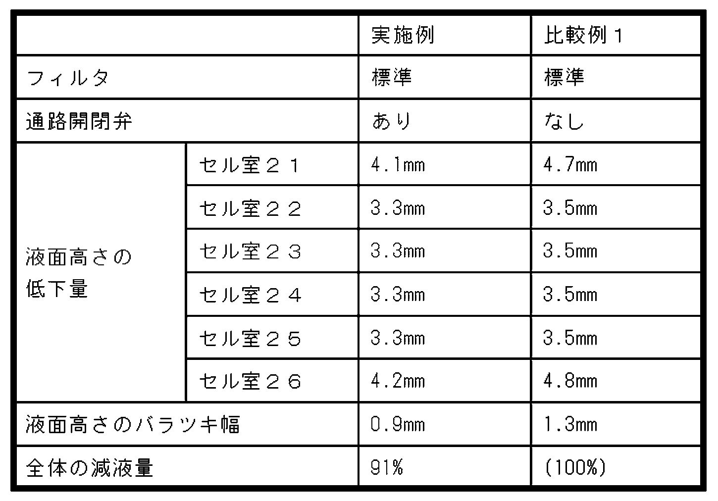
実施例は、目の細かさが標準的なフィルタをフィルタ331として用いる。通路開閉弁332及びその余の構成は、上記実施形態と同様である。
比較例1は、実施例と同じフィルタをフィルタ331として用い、通路開閉弁332を備えない。その余の構成は実施例と同様である。
比較例2は、実施例及び比較例1のフィルタよりも目の細かいフィルタをフィルタ331として用い、通路開閉弁332を備えない。その余の構成は実施例と同様である。
比較例3は、比較例2のフィルタよりも更に目の細かいフィルタをフィルタ331として用い、通路開閉弁332を備えない。その余の構成は実施例と同様である。
比較例4は、比較例3のフィルタよりも更に目の細かいフィルタをフィルタ331として用い、通路開閉弁332を備えない。その余の構成は実施例と同様である。
比較例1は、実施例と同じフィルタをフィルタ331として用い、通路開閉弁332を備えない。その余の構成は実施例と同様である。
比較例2は、実施例及び比較例1のフィルタよりも目の細かいフィルタをフィルタ331として用い、通路開閉弁332を備えない。その余の構成は実施例と同様である。
比較例3は、比較例2のフィルタよりも更に目の細かいフィルタをフィルタ331として用い、通路開閉弁332を備えない。その余の構成は実施例と同様である。
比較例4は、比較例3のフィルタよりも更に目の細かいフィルタをフィルタ331として用い、通路開閉弁332を備えない。その余の構成は実施例と同様である。
用いられるフィルタの目詰まりの発生し易さについて、過去の実験結果や製品での実績に基づいて評価した。実施例及び比較例1に用いられる標準的なフィルタは、目詰まりが発生し難い。一方、比較例2~4に用いられる目の細かいフィルタは、目詰まりが発生し易い。
フィルタ及び通路開閉弁の通気抵抗を次のようにして測定した。フィルタを円筒の内部に配置して、円筒の一方の開口から流量1リットル/分の空気を供給し、フィルタを通過する前の空気の圧力を測定する。測定された圧力から、大気圧を差し引いた値を、フィルタの通気抵抗とする。実施例については、フィルタと通路開閉弁の両方を円筒の内部に配置して測定した。結果は、実施例が0.6kPa、比較例1が0.3kPa、比較例2が0.6kPa、比較例3が1.2kPa、比較例4が1.8kPaであった。比較例1~4の結果から、フィルタの目が細かくなるにつれて、通気抵抗が大きくなっていることが分かる。また、実施例の通気抵抗は、比較例1よりも大きい。このことから、実施例では、通路開閉弁が存在することにより通気抵抗が大きくなっていることが確認された。実施例の通気抵抗と比較例1の通気抵抗の差から、通路開閉弁による通気抵抗への寄与は0.3kPaであると推測される。
減液量の評価試験を次のようにして行った。鉛蓄電池1を60℃の環境下におき、13.8Vでの定電圧充電を行いながら、上下方向の振動を加える。振動の周波数は10Hz~55Hzでスイープ、加速度は9.8m/s2とする。試験時間は120時間とする。試験開始前の鉛蓄電池1の重量と、試験終了後の鉛蓄電池1の重量との差を、試験時間(120時間)で除して、単位時間当たりの減液量[g/h]を求める。結果は、実施例が0.38g/h、比較例1が0.54g/h、比較例2が0.47g/h、比較例3が0.41g/h、比較例4が0.35g/hであった。比較例1~4の結果から、通気抵抗が大きくなるにつれて、減液量が小さくなっていると認められる。ここで、実施例の通気抵抗は比較例2と同じ0.6kPaであるが、実施例の減液量は、比較例2の減液量よりも小さい。実施例は、通路開閉弁を備えることにより、通路開閉弁を備えない比較例1~4に比べて減液量が特異的に小さくなっている。
内圧上昇の評価試験を次のようにして行った。蓋部材45に上下方向11の貫通孔を設け、当該貫通孔を通じてセル室23へ所定の流量の空気を供給し、セル室23の内圧を測定する。セル室23の内圧が所定の基準値以下である場合、合格とし、内圧が基準値より大きい場合、不合格とする。結果は、実施例、比較例1及び2は合格、比較例3及び4は不合格となった。
セル室ごとの液面高さの低下量を評価する試験を次のようにして行った。鉛蓄電池1を車両に搭載して、所定の走行パターンで車両を走行させた。試験開始前の液面高さを基準として、試験終了時の液面高さの低下量を測定した。走行パターンは、2時間の速度60km/hでの走行と2時間のアイドリングとを3回繰り返した後、12時間エンジンを停止する。このパターンを40回繰り返す。なお、鉛蓄電池1は、前面が車両の前方を向く姿勢にて、車両を前方から見てエンジンの右方に配置される。セル室21~26のうち、セル室26がエンジンの最も近い位置に配置される。表2に示されるように、実施例の液面高さの低下量は、全てのセル室21~26において、比較例1より小さくなった。実施例の全体の減液量(液面高さの低下量の合計)は、比較例1の全体の減液量の91%であった。実施例の液面高さのバラツキ幅(液面高さの低下量の最大値と最小値との差)は、比較例1よりも0.4mm小さくなった。実施例の鉛蓄電池1と比較例1の鉛蓄電池1との構成上の差異は、通路開閉弁の有無のみである。従って、鉛蓄電池1が通路開閉弁を備えることにより、電解液の減液量が減少するだけでなく、セル室21~26の減液量のバラツキの減少という予期せぬ効果が生じている。
以上の試験結果から、鉛蓄電池1が通路開閉弁を備えることによって、電解液の減少量と、複数のセル室の間の減液量のバラツキとを減少できることが確認された。電解液の減少量を、通路開閉弁を用いずに、実施例と同程度まで減少させるには、比較例3又は4に用いた目の細かいフィルタを使用する必要がある。しかし、比較例3及び4は、フィルタに目詰まりが発生し易く、内圧上昇の試験も不合格である。従って、実施例のように通路開閉弁を用いて電解液の減少を抑制することが好ましい。
[第1変形例]
上記実施形態では、フィルタ331が筒状ケーシング334に挿入され、フィルタ331と通路開閉弁332とが一体化されている例が説明されたが、フィルタ331と通路開閉弁332とは共通通路9において離れて配置されてもよい。
上記実施形態では、板状弁本体333が弁座337の上面に接触しているとき、板状弁本体333と弁座337との間に間隙340が存在する例が説明されたが、間隙340が存在しない形態も可能である。この形態では、板状弁本体333が弁座337の上面に接触しているとき、気体は通路開閉弁332を通過しない。セル室21~26及び排気通路2の内部の圧力が大きくなると、板状弁本体333が連通路335の中で上方に移動し、板状弁本体333の全部又は一部が弁座337から離間し、板状弁本体333と弁座337との間に間隙が生じる。セル室21~26で発生し排気通路2を通ったガスは、板状弁本体333と弁座337との間に生じた間隙を通ってフィルタ331に達する。
上記実施形態では、筒状ケーシング334の弁座337が突起339を備えることにより、間隙340が形成される例が説明された。板状弁本体333の下面に突起が設けられてもよい。また、突起に代えて、溝が、弁座337又は板状弁本体333に設けられることにより、間隙340が形成されてもよい。
上記実施形態では、共通通路9においてフィルタ331が通路開閉弁332よりも排気口201の側に配置される例が説明されたが、フィルタ331が通路開閉弁332よりも電槽17の側に配置されてもよい。換言すれば、通路開閉弁332がフィルタ331よりも排気口201の側に配置されてもよい。
なお、本発明の一実施形態は、以下の形で実施することができる。
(1)
開口及び当該開口に連続する収容室を有し、当該収容室内に電極群及び電解液を収容した複数のセル室が区画された電槽と、
排気口と、上記開口を封口する中蓋と、当該中蓋に設けられた上蓋と、上記中蓋と上記上蓋との間に形成され上記収容室と上記排気口とを接続する排気通路と、を有する蓋部材と、を備え、
上記排気通路は、上記各セル室と連通する複数の個別通路及び当該各個別通路に連通して上記排気口に接続する共通通路を有し、
当該共通通路に配置されたフィルタと、
同じく当該共通通路に配置された通路開閉弁と、を有する鉛蓄電池。
(1)
開口及び当該開口に連続する収容室を有し、当該収容室内に電極群及び電解液を収容した複数のセル室が区画された電槽と、
排気口と、上記開口を封口する中蓋と、当該中蓋に設けられた上蓋と、上記中蓋と上記上蓋との間に形成され上記収容室と上記排気口とを接続する排気通路と、を有する蓋部材と、を備え、
上記排気通路は、上記各セル室と連通する複数の個別通路及び当該各個別通路に連通して上記排気口に接続する共通通路を有し、
当該共通通路に配置されたフィルタと、
同じく当該共通通路に配置された通路開閉弁と、を有する鉛蓄電池。
(2)
上記共通通路において、上記フィルタは上記通路開閉弁よりも上記排気口側に配置されている、(1)に記載の鉛蓄電池。
上記共通通路において、上記フィルタは上記通路開閉弁よりも上記排気口側に配置されている、(1)に記載の鉛蓄電池。
(3)
上記通路開閉弁は、
上記共通通路と連通する連通路及び弁座が形成された筒状ケーシングと、
当該筒状ケーシング内に配置され、上記連通路を開閉する板状弁本体とを備え、
上記板状弁本体は、上記弁座に当接して上記連通路を閉じる姿勢と、上記弁座から離間して上記連通路を開く姿勢との間で姿勢変化可能に上記弁座に支持されている、(2)に記載の鉛蓄電池。
上記通路開閉弁は、
上記共通通路と連通する連通路及び弁座が形成された筒状ケーシングと、
当該筒状ケーシング内に配置され、上記連通路を開閉する板状弁本体とを備え、
上記板状弁本体は、上記弁座に当接して上記連通路を閉じる姿勢と、上記弁座から離間して上記連通路を開く姿勢との間で姿勢変化可能に上記弁座に支持されている、(2)に記載の鉛蓄電池。
[第2概要説明]
初めに、本発明の一実施形態に係る鉛蓄電池の概要について説明する。本鉛蓄電池は、開口を有し、当該開口に連続し電極群及び電解液を収容したセル室が長手壁及び短手壁により区画された電槽と、上記セル室に通ずる液口又は還流孔を有し、上記開口を封口する蓋部材と、上記液口又は還流孔を取り囲むように配置された筒状部材を備え、当該筒状部材の周面の所定位置に当該筒状部材の軸方向に延びるスリットが形成されており、上記液口又は還流孔の中心を基点として上記スリットの中心を貫く仮想線が、上記長手壁を含む仮想平面と交差する角度θが90°未満である。
本発明者は、電解液の外部漏洩を抑制すべく、ウェル(筒状部材)とスリットの形状について検討した。従来の鉛蓄電池におけるウェルのスリットは、液口又は還流孔の中心を基点としてスリットの中心を貫く仮想線が長手壁を含む仮想平面と交差する角度θが90°となる配置(特許文献1及び2の配置、以下「短手側配置」と記す。)、又は、仮想線が仮想平面に平行となる配置(特許文献3の配置、以下「長手側配置」と記す。)であった。スリットの短手側配置及び長手側配置が採用された理由は、特許文献1に記載されているように、液口栓の周囲のウェルが、作業者が電解液の液面高さを液口から覗き込んで確認する際の目印として用いられることによる。スリットを長手側配置及び短手側配置以外の中間的な位置に配置すると(以下「斜め配置」と記す。)、液面の位置が視認しにくくなるからである。
振動溢液性、すなわち、鉛蓄電池に振動が加えられたときの電解液の溢液の起こりにくさは、鉛蓄電池に振動を加えて、溢液が発生する加速度を評価する振動試験にて評価される。振動試験は、長手壁に平行な方向(以下「長手方向」と記す。)の振動と、短手壁に平行な方向(以下「短手方向」と記す。)の振動の、2種類の振動について行われる。この点からも、従来のスリットは、長手側配置又は短手側配置のいずれかが採用されていた。というのは、鉛蓄電池に振動が加えられると、加えられた振動方向に沿って電解液に波が生じる。波がスリットを通過すると、電解液が液口又は還流孔に達して溢液する場合がある。スリットを斜め配置とすると、長手方向の振動による波と短手方向の振動による波の両方がスリットを通過しやすくなって、振動試験において、長手方向の振動と短手方向の振動の両方に対して溢液しやすくなるという先入観があった。そこで、従来は、長手側配置又は短手側配置のいずれかが採用されていた。その上で、特許文献3の二重構造のウェルのように、溢液を抑制する対策が講じられていた。
実際の使用環境においては、鉛蓄電池には、あらゆる方向の振動が加えられる。例えば、自動車や二輪車に搭載された際には、鉛蓄電池には、長手方向と短手方向に加え、斜めの方向の振動も加えられる。このとき、セル内にはあらゆる方向の波が生じると考えられていた。そうすると、スリットをいずれの方向に向けても、スリットの方向と一致する方向の波に対しては溢液し易くなる。よって、スリットをいずれの方向に向けても振動溢液性は向上しないと考えられていた。
本発明者は、鉛蓄電池に振動が加えられたときにセル内に発生する電解液の波を観察した。そして、鉛蓄電池に斜め方向の振動(長手方向及び短手方向以外の方向の振動)が加えられたとき、斜め方向の波は発生せず、長手方向の波が発生するという知見を初めて得た。本発明者は、この新たな知見に基づいて検討を進め、従来のウェルのスリットを改良し、振動溢液性を改善できる可能性を見出した。
従来、ウェルのスリットは長手側配置又は短手側配置とされていた。スリットを長手側配置とすると、短手方向の振動には溢液し難くなるが、長手方向の振動には溢液し易くなる。スリットを短手側配置とすると、長手方向の振動には溢液し難くなるが、短手方向の振動には溢液しやすくなる。つまり、従来の長手側配置又は短手側配置では、スリットの方向と振動の方向とが直交する場合には溢液し難いが、スリットの方向と振動の方向とが一致した場合に、溢液し易くなるという問題点があった。だが、スリットを斜め配置とすると、長手方向と短手方向の両方の振動に対して溢液し易くなるという先入観があり、又、斜め方向の振動による斜め方向の波に対して溢液し易くなるため、スリットの斜め配置には実使用上の利点はないと考えられていた。
しかし、上記の新たな知見によれば、斜め方向の波が発生しないため、スリットを斜め配置としても、斜め方向の振動溢液性は悪化しない。ここで、スリットを斜め配置とした場合、振動試験に用いられる長手方向と短手方向の振動に対して、スリット方向と振動方向とが直交しない。そのため、振動試験において長手方向又は短手方向の一方の振動に対する振動溢液性が低下する可能性がある。しかし、スリット方向と振動方向とが一致することがなくなるため、長手方向又は短手方向の他方の振動に対する振動溢液性を向上することができる。そして、スリット方向と振動方向とが一致するという弱点がなくなることにより、溢液が発生する最小の加速度が大きくなり、総合的な振動溢液性を向上することができる。
本鉛蓄電池の実施形態として、以下の構成が好ましい。上記角度θが30°以上60°以下である。上記構成によれば、電解液の漏洩を更に抑制することができる。
上記蓋部材は、上記開口を封口する中蓋と、当該中蓋に設けられた上蓋とを有し、上記中蓋に上記還流孔が形成され、上記中蓋に形成されている上記筒状部材は、上記還流孔の周囲を囲繞し、且つ、上記電槽側に突出している。中蓋に形成された還流孔は、重力の作用で液体を集めて還流させるために、できるだけ低い位置に設けられる。すなわち、還流孔はセル室内の電解液の液面に近い位置に配置される。そのため、鉛蓄電池に振動が加えられてセル室内に電解液の波が生じた場合に、電解液が還流孔に到達しやすい。上記構成によれば、このような還流孔の周囲を囲繞して筒状部材が設けられるので、筒状部材が他の位置に設けられる場合に比べ、電解液の漏洩を抑制する効果が高い。
上記スリットを上記仮想平面へ投影した形状の幅は、上記スリットの幅よりも小さい。
[第2詳細説明]
以下、本発明の第2実施形態に係る鉛蓄電池について、適宜図面を参照しながら説明する。なお、上記第1実施形態と共通する構成については、該第1実施形態で用いた図面を流用する。
以下、本発明の第2実施形態に係る鉛蓄電池について、適宜図面を参照しながら説明する。なお、上記第1実施形態と共通する構成については、該第1実施形態で用いた図面を流用する。
1.全体の構成
鉛蓄電池1は、流動可能な電解液を備える液式蓄電池である。鉛蓄電池1は、図1から図3に示されるように、電槽17と、電極群30と、電解液14と、端子部38及び39と、蓋部材45とを備える。なお、鉛蓄電池1が設置面に対して傾きなく水平に置かれたときの使用姿勢を基準として上下方向11が定義される。端子部38及び39の並び方向であって電槽17の横幅方向を左右方向13とし、電槽17の奥行方向を前後方向12とする。端子部38及び39が配置された前後方向12の一方を後方とする。上下方向11は、筒状部材の軸方向の一例である。
電槽17は、4枚の外壁27と、底壁28とを備えており、上面が開放された合成樹脂製の箱型の部材である。電槽17は、開口18及び当該開口18に連続する収容室19を有する。電槽17は、図2に示されるように、左右方向13に等間隔に配置された5枚の隔壁29を備える。隔壁29は、電槽17の収容室19を6つのセル室21~26に仕切る。すなわち、隔壁29により、電槽17の収容室19に6つのセル室21~26が、右方から左方へ順番に、左右方向13に並んで形成されている。各セル室21~26に、希硫酸からなる電解液14と、電極群30とが収容されている。すなわち、収容室19内に、開口18に連続し、電極群30及び電解液14を収容した複数のセル室21~26が、隔壁29及び外壁27により区画されている。複数のセル室21~26が、収容室19内に並設されている。本実施形態では、セル室21~25は、前後方向12(長手方向)の大きさが、左右方向13(短手方向)の大きさよりも大きい。セル室21~25の前後方向12の大きさは、左右方向13の大きさの2.5倍以上であると好ましく、6.3倍以下であると好ましい。本実施形態では、図2に例示されるように、セル室21~25の前後方向12の大きさが、左右方向13の大きさの4.1倍である。隔壁29は、長手壁の一例である。前方及び後方の外壁27は、短手壁の一例である。
電極群30は、図3に示されるように、正極板31と、負極板32と、セパレータ33とから構成されている。セパレータ33は、正極板31と負極板32との間に配置され、正極板31と負極板32とを仕切る。正極板31と負極板32とは、格子体に活物質が充填されて構成されている。正極板31の活物質の主成分は二酸化鉛であり、負極板32の活物質の主成分は鉛である。
図3に示すように、正極板31の上部に耳部34が設けられ、負極板32の上部に耳部35が設けられている。セル室21~26の内部において、耳部34は正極用のストラップ36に接続され、耳部35は負極用のストラップ36に接続されている。ストラップ36は、左右方向13に延びる板状の部材である。これにより、セル室内の正極板31が正極用のストラップ36によって電気的に接続され、セル室内の負極板32が負極用のストラップ36によって電気的に接続されている。そして、隣接するセル室の正負のストラップ36同士が、ストラップ36に形成された接続部37を介して電気的に接続されている。これにより、6つのセル室21~26の電極群30が、電気的に直列に接続されている。
蓋部材45は、電槽17の開口18を封口する中蓋50と、中蓋50に設けられた上蓋100とを備える。図4は、上蓋100を外した状態で中蓋50を上方から見た平面図であり、図14は、中蓋50を下方から見た底面図である。中蓋50は、合成樹脂製であって、図4及び図14に示されるように、蓋板51とフランジ部52とを備える。
蓋板51は、電槽17の上方の開口を封口可能な大きさの部材である。蓋板51は、図14に示すように、その下面に、フランジ部52に沿った形状の周壁53と、周壁53に連なって形成された複数の蓋側隔壁54とを備える。
周壁53は、蓋板51の下面から下方へ突出している。周壁53は、電槽17の開口縁部に対応するように略矩形状に形成されている。蓋側隔壁54は、蓋板51の下面から下方へ突出している。各蓋側隔壁54は、電槽17の各隔壁29に対応するように、周壁53の内側を仕切る。そして、周壁53を電槽17の開口縁部に重ね、蓋側隔壁54を電槽17の隔壁29に重ね、これらを熱溶着により接合する。これにより、周壁53と電槽17との間、及び、蓋側隔壁54と隔壁29との間の気密性が確保されている。
また、蓋板51は、図1及び図3に示されるように、高面部55と低面部56とを備える。高面部55は、蓋板51の前方と後方とに設けられている。後方の高面部55の左右方向13の両端には、一対の端子部が配置されている。詳しくは、後方の高面部55の左方の端部に、正極側端子部38が配置され、右方の端部に、負極側端子部39が配置されている。正極側端子部38と負極側端子部39とはほぼ同じ形状であるため、以下、負極側端子部39を例として説明し、正極側端子部38の説明を省略する。
負極側端子部39は、図3に示されるように、ブッシング41と、極柱42とを備える。ブッシング41は、鉛合金等の金属製であり、中空の円筒状の部材である。ブッシング41は、図3に示されるように、高面部55に形成された筒型の装着部67に装着されている。ブッシング41は、装着部67を貫通しており、ブッシング41の上部が、高面部55の上面から突出している。ブッシング41のうち、高面部55から突出する部位は、端子接続部であり、ハーネス端子などの接続端子(図示なし)が組み付けられる。
極柱42は、鉛合金等の金属製の部材であり、円柱形状である。極柱42は、ブッシング41の内側に位置している。極柱42はブッシング41に比べて長く、極柱42の上部はブッシング41の内側に位置し、極柱42の下部はブッシング41の下面から下方に突出している。極柱42の上端部(先端)は、ブッシング41に溶接により接合され、極柱42の基端部43は、電極群30のストラップ36に接合されている。
中蓋50の低面部56は、蓋板51の前方寄りに形成されている。低面部56は、電槽17に設けられた6つのセル室21~26を横断して左右方向13に延びて設けられている。低面部56の上面は、高面部55の上面よりも低い位置にある。
図4及び図14に示されるように、中蓋50の低面部56の上面壁57は、左右方向13に並ぶ6つの注液孔68を備える。これら6つの注液孔68は、低面部56の上面壁57を上下方向11に貫通しており、6つのセル室21~26にそれぞれ連通している。
また、低面部56は、図4に示されるように、上面壁57の上面から上方へ突出した下側筒壁69、下側外周壁70、及び下側隔壁71を備える。下側筒壁69は、注液孔68を囲む円筒状の隔壁であり、6つの注液孔68のそれぞれに設けられている。下側外周壁70は、低面部56の外縁に沿って設けられ、低面部56を囲む略矩形状の隔壁である。下側隔壁71は、後方の下側外周壁70から前方へ延びる隔壁であって、電槽17の各隔壁29に対応して設けられている。
上蓋100は、合成樹脂製である。図6は、上蓋100を上方から見た平面図であり、図15は、上蓋100を下方から見た底面図である。上蓋100は、図6及び図15に示されるように、蓋本体101と、フランジ部103とを備える。蓋本体101は、中蓋50の低面部56に倣う長方形の部材であり、中蓋50の低面部56に対して重ねて取り付けられる。フランジ部103は、蓋本体101の左方と右方の外周縁に形成されている。フランジ部103は、蓋本体101から下方に突出しており、中蓋50の低面部56の左方及び右方の端部の外側に位置する。
図6及び図15に示されるように、蓋本体101の上面壁102は、左右方向13に並ぶ6つの注液孔104を備える。これら6つの注液孔104は、中蓋50の注液孔68に対応する位置に形成され、蓋本体101の上面壁102を上下方向11に貫通しており、6つのセル室21~26にそれぞれ連通している。各注液孔104及び各注液孔68を通して、電槽17の各セル室21~26に電解液14が注液される。なお、図1に示されるように、各注液孔104に、液口栓105が取り付けられて、注液孔104が閉じられる。
また、蓋本体101は、上面壁102の下面から下方へ突出した上側筒壁106、上側外周壁107、及び上側隔壁108を備える。上側筒壁106は、注液孔104を囲む円筒状の隔壁であり、6つの注液孔104のそれぞれに設けられている。上側外周壁107は、蓋本体101の外縁に沿ってフランジ部103の内側に設けられた、略矩形状の隔壁である。上側隔壁108は、後方の上側外周壁107から前方へ延びる隔壁であって、電槽17の各隔壁29に対応して設けられている。
各上側筒壁106は、各下側筒壁69に対応している。上蓋100が中蓋50の低面部56に配置されるとき、各上側筒壁106は、各下側筒壁69の上方に重なって配置される。各上側筒壁106と各下側筒壁69とは熱溶着により接合され、各上側筒壁106と各下側筒壁69との間の気密性が確保されている。
上側外周壁107は、下側外周壁に対応している。上蓋100が中蓋50の低面部56に配置されるとき、上側外周壁107は、下側外周壁70の上方に重なって配置される。上側外周壁107と下側外周壁70とは熱溶着により接合され、上側外周壁107と下側外周壁70との間の気密性が確保されている。
各上側隔壁108は、各下側隔壁71に対応している。上蓋100が中蓋50の低面部56に配置されるとき、各上側隔壁108は、各下側隔壁71の上方に重なって配置される。各上側隔壁108と各下側隔壁71とは熱溶着により接合され、各上側隔壁108と各下側隔壁71との間の気密性が確保されている。
図4に示されるように、中蓋50の低面部56は、左右方向13に並ぶ6つの還流孔77を備える。各還流孔77は、図8に示されるように、後述する下側外周壁70、下側隔壁71、下側周壁73、及び下側通路壁61に囲まれた領域に位置している。各還流孔77は、低面部56の上面壁57を上下方向11に貫通し、電槽17の各セル室21~26に連通する。本実施形態では、還流孔77は、図4及び図14に示されるように、電槽17の各セル室21~26を上下方向11に見た中央部に配置されている。すなわち、還流孔77は、電槽17の各セル室21~26の中央部に配置されている。これにより、鉛蓄電池1が左方、右方、前方、後方のいずれの方向に倒れた場合でも、還流孔77からの電解液14の流出が抑制される。
そして、個別通路81~86(後述)の底面である低面部56の上面壁57の上面は、還流孔77に近いほど上下方向11に関して低くなるように、傾斜している。これにより、セル室21~26からのガスに含まれる水蒸気による水滴や、電解液等の液滴を、還流孔77を通じてセル室21~26へ還流することができる。すなわち、セル室21~26で発生したガスに含まれる水蒸気は、ガスが個別通路81~86を通過する際に、個別通路81~86内にて結露する。結露した液滴は、上面壁57の上面の傾斜によって、還流孔77に向かって流れていく。そのため、ガスに含まれる水蒸気等の液滴を、各セル室21~26に還流することができる。
2.ウェル及びスリット
図14及び図17に示されるように、中蓋50は、左右方向13に並ぶ6つのウェル130を備える。ウェル130は、円筒状の部材であって、中心軸が上下方向11に平行となる姿勢にて、還流孔77の周囲を取り囲むように配置されている。ウェル130は、還流孔77の周囲を囲繞する。ウェル130は、中蓋50の上面壁57の下面から下方、すなわち電槽17の側へ突出している。ウェル130は、蓋側隔壁54及び隔壁29に沿う平坦な部位である平坦部131と、当該平坦部131に連続し還流孔77を取り囲む湾曲部132とを有している。平坦部131は、還流孔77の左方又は右方の周縁から下方へ延びている。ウェル130は、筒状部材の一例である。
図14及び図17に示されるように、ウェル130の周面の所定位置に、上下方向11に延びるスリット133が形成されている。スリット133は、ウェル130の下方の端部から、上面壁57の下面まで延びている。本実施形態では、スリット133は、ウェル130の湾曲部132に形成されている。スリット133は、ウェル130の内部の空間と外部の空間とに連通している。
図18を参照して、ウェル130におけるスリット133の位置について説明する。図18は、中蓋50の底面図である。図18には、還流孔77の中心134と、スリット133の中心135とが示されている。なお、還流孔77の中心134とは、還流孔77を上下方向11に見た図形の重心である。例えば、還流孔77が円形の場合は、中心134は当該円形の中心である。還流孔77が矩形の場合は、中心134は当該矩形の対角線の交点である。スリット133の中心135とは、スリット133の一方の端と他方の端とを結ぶ線分の中点である。図18において、還流孔77の中心134を基点として、スリット133の中心135を貫く仮想線136と、電槽17の隔壁29を含む仮想平面137とを考える。なお、電槽17の隔壁29は、中蓋50の蓋側隔壁54に対応するので、仮想平面137は蓋側隔壁54を含む平面である。本実施形態では、仮想線136と仮想平面137とは交差している。仮想線136が仮想平面137と交差する角度θは、90°未満である。すなわち、仮想線136と仮想平面137とは直交していない。図示例では、角度θは45°である。なお、角度θは、30°以上60°以下であると好ましい。なお、角度θは、仮想線136と仮想平面137とがなす鋭角及び鈍角のうち、鋭角である。
本実施形態では、還流孔77の前後方向12の大きさ、及び、左右方向13の大きさは、共に3mmである。ウェル130の湾曲部132の曲率半径は6mmであり、湾曲部132と平坦部131との間の接続部の曲率半径は3mmである。スリット133の幅138は3mmである。スリット133を仮想平面137へ投影した形状の幅139は、2.1mmであり、スリット133の幅138よりも小さい。
図17及び図18に示されるように、中蓋50は、平板141及び平板142を有する。平板141及び平板142は、6つの還流孔77ごとに設けられている。平板141は、矩形の平板であって、還流孔77の周縁に配置されている。平板141は、中蓋50の上面壁57の下面から下方へ突出している。つまり、平板141は、還流孔77の周縁から電槽17の側へ延びている。平板141は、還流孔77の右方又は左方に配置されている。詳しくは、平板141は、ウェル130の平坦部131に対して、還流孔77を挟んで左右方向13の反対側に配置されている。図17の例では、平板141は、還流孔77の右方に配置されている。
平板142は、矩形の平板である。平板142は、還流孔77の下方に配置されている。平板142の左右方向13の一方の端部(図17の例では右方の端部)は、平板141の下方の端部に連結している。平板142の左右方向13の他方の端部(図17の例では左方の端部)は、ウェル130の平坦部131の側面に接続している。
図17及び図18に示されるように、平板141、平板142、及びウェル130の平坦部131によって、前後方向12に沿う2カ所に、開口143、144が形成されている。開口143、144は、還流孔77と連通する。個別通路81~86から還流孔77へ流れ込んだ液滴は、平板141又はウェル130の平坦部131と接触して下方へ案内され、開口143、144を通って電槽17のセル室21~26に還流する。すなわち、平板141及びウェル130の平坦部131は、還流孔77へ還流した液滴を電槽17のセル室21~26へ案内する。
3.排気通路
図4及び図15に示されるように、蓋部材45は、中蓋50と上蓋100との間に、排気通路2を備えている。排気通路2は、電槽17の収容室19、及び、蓋部材45に設けられた排気口201を接続する通路である。排気通路2は、電槽17のセル室21~26で発生するガスを、排気口201へ導き、鉛蓄電池1の外部へ排出する通路である。排気通路2は、複数の個別通路81~86及び共通通路9を含む。
本実施形態では、蓋部材45は、6つの個別通路81~86を備えている。個別通路81~86は、6つのセル室21~26にそれぞれ連通する。
共通通路9は、個別通路81~86と連通し、排気口201に接続する通路である。共通通路9は、7つの通路91~97により構成されている。
図4及び図15に示されるように、個別通路81及び通路91と、個別通路86及び通路96とは、法線が左右方向13に平行で蓋部材45の左右方向13の中央を通る平面15に関して対称な形状である。同様に、個別通路82及び通路92と、個別通路85及び通路95とは、平面15に関して対称な形状である。個別通路83及び通路93と、個別通路84及び通路94とは、平面15に関して対称な形状である。そして個別通路82及び通路92と、個別通路83及び通路93とは、概ね同じ形状である。
4.個別通路
個別通路81~86は、中蓋50と上蓋100との間において、電槽17のセル室21~26ごとに設けられている。個別通路81~86は、共通通路9に連通しており、セル室21~26から流出するガスを共通通路9へ流す機能を果たす。個別通路81~86は、セル室側の末端に設けられた排気部6と、後述する下側通路壁61~66及び上側通路壁111~116により形成される通路とを含む。排気部6は、概ね筒型であり、内部がガスの通り道である。
まず、排気部6について具体的に説明する。図4に示されるように、中蓋50の低面部56は、左右方向13に並ぶ6つの下側筒部78を備える。下側筒部78は、図4及び図8に示されるように、角筒形状であり、下側外周壁70の一部と、下側隔壁71の一部と、2つの下側周壁72、73とから構成されている。2つの下側周壁72、73は、低面部56の上面壁57の上面から上方に突出している。
また、図4に示されるように、低面部56の上面壁57は、左右方向13に並ぶ6つの連通孔74を備える。各連通孔74は、各下側筒部78の内側に位置している。各連通孔74は、低面部56の上面壁57を上下方向11に貫通し、電槽17の各セル室21~26に連通する。
上蓋100の蓋本体101は、図15に示されるように、左右方向13に並ぶ6つの上側筒部118を備える。上側筒部118は、図15及び図16に示されるように、角筒形状であり、上側外周壁107の一部と、上側隔壁108の一部と、2つの上側周壁109、110とから構成されている。2つの上側周壁109、110は、蓋本体101の上面壁102の下面から下方に突出している。
各下側筒部78と各上側筒部118とは、上下に重なって一つの排気部6を構成する。詳しくは、上側周壁109は、下側周壁72に対応しており、対応する下側周壁72の上に重なって、熱溶着により接合される。一方、上側周壁110は、下側周壁73の上に重ならず、下側周壁73よりも右方に位置する(なお、右端の排気部6においては、上側周壁110は下側周壁73よりも左方に位置する)。上述の通り、上側外周壁107及び上側隔壁108は、対応する下側外周壁70及び下側隔壁71の上に重なって、熱溶着により接合される。
以上のように構成された各排気部6は、各連通孔74を通じて各セル室21~26に連通する。そのため、電槽17の各セル室21~26にて発生したガスは、連通孔74を通って各排気部6の内部に流入し、左右方向13に離間した上側周壁110と下側周壁73との間から流出し、個別通路81~86を排気口201へ向けて流れる。
次に、下側通路壁61~66及び上側通路壁111~116により形成される通路について具体的に説明する。図8に示されるように、中蓋50の低面部56は、電槽17のセル室21~26ごとに、複数の下側通路壁61~66を有している。下側通路壁61~66は、低面部56の上面壁57の上面から上方に突出している。
下側通路壁61は、下側筒部78の下側周壁72を左方に延長した壁であり、下側周壁72と連続して形成されている。下側通路壁61の左方の先端は、下側隔壁71の近傍で右斜め後方へ折れ曲がり、下側外周壁70の近傍まで延びている。
下側通路壁62は、下側隔壁71から突出して右斜め後方へ延びる壁である。下側通路壁62の右方の先端は、下側通路壁65の近傍で後方へ折れ曲がり、下側通路壁61の近傍まで延びている。
下側通路壁63は、下側通路壁62から突出して後方へ延びる壁であり、その先端は下側通路壁61の近傍に位置する。
下側通路壁64は、下側隔壁71から突出して左方へ延び、途中から左斜め後方へ延びる壁である。下側通路壁64の先端は、左方の下側隔壁71の近傍で後方へ折れ曲がり、下側通路壁62の近傍まで延びている。
下側通路壁65は、下側通路壁64から突出して後方へ延びる壁であり、その先端は下側通路壁61の近傍に位置する。
下側通路壁66は、下側隔壁71から突出して右方へ延びる壁であり、その先端は、右方の下側隔壁71の近傍に位置する。
以上説明した下側通路壁61~66は、図8に示されるように、向きの異なる壁の集合体である。上述の通り、下側通路壁61~66は、他の下側通路壁61~66や下側隔壁71と連結されており、これらの壁が屈曲した形状となっている。これにより、個別通路81~86の経路が、非直線の迷路形状となる。すなわち、蓋部材45は、個別通路81~86を屈曲させる通路壁である下側通路壁61~66を有する。
図16に示されるように、上蓋100の蓋本体101は、電槽17のセル室21~26ごとに、複数の上側通路壁111~116を有している。上側通路壁111~116は、蓋本体101の上面壁102の下面から下方に突出している。
上側通路壁111は、上側筒部118の上側周壁109を左方に延長した壁であり、上側周壁109と連続して形成されている。上側通路壁111の左方の先端は、上側隔壁108の近傍で右斜め後方へ折れ曲がり、上側外周壁107の近傍まで延びている。
上側通路壁112は、上側隔壁108から突出して右斜め後方へ延びる壁である。上側通路壁112の右方の先端は、上側通路壁115の近傍で後方へ折れ曲がり、上側通路壁111の近傍まで延びている。
上側通路壁113は、上側通路壁112から突出して後方へ延びる壁であり、その先端は上側通路壁111の近傍に位置する。
上側通路壁114は、上側隔壁108から突出して左方へ延び、途中から左斜め後方へ延びる壁である。上側通路壁114の先端は、左方の上側隔壁108の近傍で後方へ折れ曲がり、上側通路壁112の近傍まで延びている。
上側通路壁115は、上側通路壁114から突出して後方へ延びる壁であり、その先端は上側通路壁111の近傍に位置する。
上側通路壁116は、上側隔壁108から突出して右方へ延びる壁であり、その先端は、右方の上側隔壁108の近傍に位置する。
以上説明した上側通路壁111~116は、図16に示されるように、向きの異なる壁の集合体である。上述の通り、上側通路壁111~116は、他の上側通路壁111~116や上側隔壁108と連結されており、これらの壁が屈曲した形状となっている。これにより、個別通路81~86の経路が、非直線の迷路形状となる。すなわち、蓋部材45は、個別通路81~86を屈曲させる通路壁である上側通路壁111~116を有する。
上側通路壁111~116と下側通路壁61~66とは、上下に重なって通路壁を形成する。詳しくは、上側通路壁111~116は、下側通路壁61~66に対応しており、対応する下側通路壁61~66の上に重なって、熱溶着により接合される。このようにして形成された通路壁、下側隔壁71、上側隔壁108、下側外周壁70、及び上側外周壁107の間に、個別通路81~86が設けられている。
図8に示されるように、個別通路82及び83の経路は、連通孔74を始点として、下側通路壁61と下側外周壁70との間を左方へ進み、下側通路壁61と下側隔壁71との間を下方へ進む。次に、経路は、下側通路壁61と下側通路壁62との間を右方へ進み、下側通路壁62と下側通路壁65との間を下方へ進む。次に、経路は、下側通路壁62と下側通路壁64との間を左方へ進み、下側通路壁64と下側隔壁71との間を下方へ進む。そして、経路は、下側通路壁64と下側通路壁66との間を右方へ進み、下側通路壁66と下側隔壁71との隙間を終点とする。終点において、個別通路82及び83は、共通通路9へ合流する。
図8に示されるように、個別通路81の経路は、連通孔74を始点として、下側通路壁61と下側外周壁70との間を右方へ進み、下側通路壁61と下側外周壁70との間を下方へ進む。次に、経路は、下側通路壁61と下側通路壁62との間を左方へ進み、下側通路壁62と下側通路壁65との間を下方へ進む。次に、経路は、下側通路壁62と下側通路壁64との間を右方へ進み、下側通路壁64と下側筒部79との間を下方へ進む。そして、経路は、下側通路壁64と下側筒部79との隙間を終点とする。終点において、個別通路81は、共通通路9へ合流する。
なお、ここでは、図8に示される中蓋50の側について説明を行ったが、図16に示される上蓋100の側についても同様の経路である。また、個別通路84~86については、上記の個別通路81~83と平面15に関して対称な形状であるから、説明を省略する。
5.共通通路
共通通路9は、中蓋50と上蓋100との間に設けられている。共通通路9は、各個別通路81~86に連通して排気口201に接続する。共通通路9は、個別通路81~86から流入するガスを集合させ、排気口201から鉛蓄電池1の外部へ排出する。本実施形態では、図4及び図15に示されるように、共通通路9は、7つの通路91~97により構成されている。通路97の排気口201側の末端に、一括排気部3が設けられている。
まず、一括排気部3について説明する。一括排気部3は、中蓋50と上蓋100との間に設けられており、セル室21~26で発生したガスを鉛蓄電池1の外部へ一括して排気する機能を果たす。本実施形態では、一括排気部3は、図15に示されるように、蓋部材45の右方の端に配置されている。なお、一括排気部3は他の位置に配置されてもよく、例えば、蓋部材45の左方の端に配置されてもよい。
詳しくは、図8に示されるように、中蓋50の低面部56は、下側筒部79を備える。下側筒部79は、低面部56の上面壁57の上面から上方に突出している。下側筒部79は、右端の下側筒壁69及び下側外周壁70に連結している。
図16に示されるように、上蓋100の蓋本体101は、上側筒部119と、排気ダクト200とを備える。上側筒部119は、蓋本体101の上面壁102の下面から下方に突出している。上側筒部119は、右端の上側筒壁106及び上側外周壁107に連結している。排気ダクト200の左方の端部は、上側筒部119の内部の空間に接続されている。排気ダクト200の右方の端部は、上蓋100の右方の側面に形成された排気口201に接続されている。
上側筒部119の内部の空間に、フィルタ205が収納されている。フィルタ205の下面は、上側筒部119の下面よりも上方に位置している。フィルタ205は、外部スパークが鉛蓄電池1の内部に侵入するのを抑制する。フィルタ205は、円板状の部材であって、例えば連続した空孔を有する多孔質体である。多孔質体は、例えば、アルミナ等のセラミックスや、ポリプロピレン等の樹脂粒子の焼結体である。フィルタ205の孔径は、例えば、平均径が数十~数百μmである。
上側筒部119と下側筒部79とは、上下に重なって熱溶着されて、一括排気部3を形成する。通路97からのガスが、下側筒部79の前方の開口から下側筒部79の内部の空間に流入し、フィルタ205を通過する。フィルタ205を通過したガスは、上側筒部119の上方の空間から排気ダクト200に流入し、排気口201を通って鉛蓄電池1の外部へ放出される。
続いて、通路91~97について説明する。通路91~97は、下側連結壁76と、上側連結壁117と、上述した下側筒壁69、下側外周壁70、下側隔壁71、下側筒部79、上側筒壁106、上側外周壁107、上側隔壁108、及び上側筒部119により形成される。
図8に示されるように、中蓋50の低面部56は、下側連結壁76を備える。下側連結壁76は、低面部56の上面壁57の上面から上方に突出している。下側連結壁76は、右方の下側筒壁69、左方の下側筒壁69、及び下側隔壁71と連結している。
図16に示されるように、上蓋100の蓋本体101は、上側連結壁117を備える。上側連結壁117は、蓋本体101の上面壁102の下面から下方に突出している。上側連結壁117は、右方の上側筒壁106及び左方の上側筒壁106と連結している。
上側連結壁117と下側連結壁76とは、上下に重なって通路壁を形成する。詳しくは、上側連結壁117は下側連結壁76に対応しており、対応する下側連結壁76の上に重なって、熱溶着により接合される。このようにして形成された通路壁、下側筒壁69、下側外周壁70、下側隔壁71、下側筒部79、上側筒壁106、上側外周壁107、上側隔壁108、及び上側筒部119の間に、通路91~97が設けられている。
図16に示されるように、通路91の経路は、個別通路81の終点(上側通路壁114と上側筒部119との隙間)を始点として、上側筒部119及び上側筒壁106と、上側通路壁114及び上側隔壁108との間を左斜め前方へ進む。次に、経路は、上側隔壁108と上側連結壁117との隙間を通り、上側隔壁108と上側筒壁106との間を通って下方へ進み、個別通路82の終点(上側通路壁116と上側隔壁108との隙間)を終点とする。
図16に示されるように、通路92の経路は、個別通路82及び通路91の終点(上側通路壁116と上側隔壁108との隙間)を始点として、上側通路壁116及び上側隔壁108と上側筒壁106との間を左方へ進む。次に、経路は、上側隔壁108と上側連結壁117との隙間を通り、上側隔壁108と上側筒壁106との間を通って下方へ進み、個別通路83の終点(上側通路壁116と上側隔壁108との隙間)を終点とする。
図16に示されるように、通路93の経路は、個別通路83及び通路92の終点(上側通路壁116と上側隔壁108との隙間)を始点として、上側通路壁116と上側筒壁106との間を左方へ進む。次に、経路は、上側隔壁108と上側筒壁106との間を左斜め前方へ進み、上側隔壁108と上側外周壁107との隙間を終点とする。
図16に示されるように、通路97の経路は、通路93の終点(上側隔壁108と上側外周壁107との隙間)を始点として、上側筒壁106及び上側連結壁117と、上側外周壁107との間を右方へ、次いで後方へ進み、一括排気部3を終点とする。
なお、ここでは、図16に示される上蓋100の側について説明を行ったが、図8に示される中蓋50の側についても同様の経路である。また、通路94~96については、上記の通路91~93と平面15に関して対称な形状であるから、説明を省略する。
以上説明した排気通路2による、各セル室21~26で発生したガスの排気について、図4を参照して説明する。
左右方向13の右方の端に位置するセル室21で発生したガスは、個別通路81と、通路91と、通路92と、通路93と、通路97と、一括排気部3を通って、排気口201から鉛蓄電池1の外部へ排出される。セル室21の左方に隣接して位置するセル室22で発生したガスは、個別通路82と、通路92と、通路93と、通路97と、一括排気部3を通って、排気口201から鉛蓄電池1の外部へ排出される。セル室22の左方に隣接して位置するセル室23で発生したガスは、個別通路83と、通路93と、通路97と、一括排気部3を通って、排気口201から鉛蓄電池1の外部へ排出される。
セル室21~23から一括排気部3までの排気通路2の長さ(通路長)を比較する。セル室21の通路長は、個別通路81と、通路91と、通路92と、通路93と、通路97の長さの合計である。セル室22の通路長は、個別通路82と、通路92と、通路93と、通路97の長さの合計である。従って、セル室21の通路長はセル室22の通路長よりも長い。セル室23の通路長は、個別通路83と、通路93と、通路97の長さの合計である。従って、セル室22の通路長はセル室23の通路長よりも長い。
左右方向13の左方の端に位置するセル室26で発生したガスは、個別通路86と、通路96と、通路95と、通路94と、通路97と、一括排気部3を通って、排気口201から鉛蓄電池1の外部へ排出される。セル室26の右方に隣接して位置するセル室25で発生したガスは、個別通路85と、通路95と、通路94と、通路97と、一括排気部3を通って、排気口201から鉛蓄電池1の外部へ排出される。セル室25の右方に隣接して位置するセル室24で発生したガスは、個別通路84と、通路94と、通路97と、一括排気部3を通って、排気口201から鉛蓄電池1の外部へ排出される。
セル室24~26から一括排気部3までの排気通路2の長さ(通路長)を比較する。セル室26の通路長は、個別通路86と、通路96と、通路95と、通路94と、通路97の長さの合計である。セル室25の通路長は、個別通路85と、通路95と、通路94と、通路97の長さの合計である。従って、セル室26の通路長はセル室25の通路長よりも長い。セル室24の通路長は、個別通路84と、通路94と、通路97の長さの合計である。従って、セル室25の通路長はセル室24の通路長よりも長い。
すなわち、左右方向13の端に位置するセル室21及びセル室26から一括排気部3(フィルタ205)までの排気通路2の長さは、その余のセル室22、23、24、及び25から一括排気部3(フィルタ205)までの排気通路2の長さよりも長い。
[第2実施例]
次に説明する実施例1~3および比較例1,2は、上記第2詳細説明欄で説明した鉛蓄電池1の実施例および比較例であり、実施例1~3および比較例1,2に対する試験結果は、後述の表3に記載されている。鉛蓄電池1に前後方向12、左右方向13、及び斜め45°方向の振動を加え、溢液が生じる振動加速度を測定する試験を、以下の条件で行った。なお、斜め45°方向とは、前後方向12と左右方向13とに対して45°の角度をなす方向であり、角度θが45°の場合の仮想線136(図18参照)が延びる方向である。
(1)図18に示される角度θが以下の通り異なる5種類の鉛蓄電池1に対して試験を行う。角度θ以外の構成は、上記実施形態と同様とする。すなわち、5種類の鉛蓄電池1は、スリット133の位置のみが異なる。電解液14の液面は、ウェル130の下端から10mmである。
実施例1:角度θ=30°
実施例2:角度θ=45°
実施例3:角度θ=60°
比較例1:角度θ=0°(仮想線136と仮想平面137とが平行)
比較例2:角度θ=90°
(2)振動の周波数を15Hzとする。加速度1.0G(=9.8m/s2)にて振動を10分間加えて、溢液を判定する。個別通路81~86の終点(下側通路壁66と下側隔壁71との隙間)に電解液14が到達した場合に、溢液したと判定する。溢液しない場合、振動加速度を0.5G増加させて、再び10分間振動を加え、溢液を判定する。溢液したときの加速度を、溢液加速度とする。つまり、溢液加速度が大きいほど、溢益しにくく、振動溢液性が優れていることになる。各振動方向の溢液加速度のうち、最も小さいものを最小溢液加速度とする。
(1)図18に示される角度θが以下の通り異なる5種類の鉛蓄電池1に対して試験を行う。角度θ以外の構成は、上記実施形態と同様とする。すなわち、5種類の鉛蓄電池1は、スリット133の位置のみが異なる。電解液14の液面は、ウェル130の下端から10mmである。
実施例1:角度θ=30°
実施例2:角度θ=45°
実施例3:角度θ=60°
比較例1:角度θ=0°(仮想線136と仮想平面137とが平行)
比較例2:角度θ=90°
(2)振動の周波数を15Hzとする。加速度1.0G(=9.8m/s2)にて振動を10分間加えて、溢液を判定する。個別通路81~86の終点(下側通路壁66と下側隔壁71との隙間)に電解液14が到達した場合に、溢液したと判定する。溢液しない場合、振動加速度を0.5G増加させて、再び10分間振動を加え、溢液を判定する。溢液したときの加速度を、溢液加速度とする。つまり、溢液加速度が大きいほど、溢益しにくく、振動溢液性が優れていることになる。各振動方向の溢液加速度のうち、最も小さいものを最小溢液加速度とする。
試験結果は次の通りである。
実施例1(角度θ=30°)の溢液加速度は、前後方向12の振動に対して6.0G、左右方向13の振動に対して5.5G、斜め45°方向の振動に対して6.0Gであった。最小溢液加速度は5.5Gである。
実施例2(角度θ=45°)の溢液加速度は、前後方向12の振動に対して6.5G、左右方向13の振動に対して5.5G、斜め45°方向の振動に対して6.5Gであった。最小溢液加速度は5.5Gである。
実施例3(角度θ=60°)の溢液加速度は、前後方向12の振動に対して6.5G、左右方向13の振動に対して5.0G、斜め45°方向の振動に対して6.5Gであった。最小溢液加速度は5.0Gである。
比較例1(角度θ=0°)の溢液加速度は、前後方向12の振動に対して4.5G、左右方向13の振動に対して6.0G、斜め45°方向の振動に対して4.5Gであった。最小溢液加速度は4.5Gである。
比較例2(角度θ=90°)の溢液加速度は、前後方向12の振動に対して7.0G、左右方向13の振動に対して4.0G、斜め45°方向の振動に対して7.0Gであった。最小溢液加速度は4.0Gである。
以上の試験結果を表3に示す。
実施例1(角度θ=30°)の溢液加速度は、前後方向12の振動に対して6.0G、左右方向13の振動に対して5.5G、斜め45°方向の振動に対して6.0Gであった。最小溢液加速度は5.5Gである。
実施例2(角度θ=45°)の溢液加速度は、前後方向12の振動に対して6.5G、左右方向13の振動に対して5.5G、斜め45°方向の振動に対して6.5Gであった。最小溢液加速度は5.5Gである。
実施例3(角度θ=60°)の溢液加速度は、前後方向12の振動に対して6.5G、左右方向13の振動に対して5.0G、斜め45°方向の振動に対して6.5Gであった。最小溢液加速度は5.0Gである。
比較例1(角度θ=0°)の溢液加速度は、前後方向12の振動に対して4.5G、左右方向13の振動に対して6.0G、斜め45°方向の振動に対して4.5Gであった。最小溢液加速度は4.5Gである。
比較例2(角度θ=90°)の溢液加速度は、前後方向12の振動に対して7.0G、左右方向13の振動に対して4.0G、斜め45°方向の振動に対して7.0Gであった。最小溢液加速度は4.0Gである。
以上の試験結果を表3に示す。

実施例1~3及び比較例1~2について、斜め45°方向の振動の溢液加速度は、前後方向12の振動の溢液加速度と同じ値となった。これは、斜め45°方向の振動を加えた場合に、セル室21~26において、前後方向12の振動を加えた場合と同様の波が発生していることを示している。
実施例1~3は、比較例1に比べ、前後方向12の振動の溢液加速度が1.5~2.0G大きくなった。これは、比較例1では仮想線136の延びる方向が振動の方向と一致しており、振動による波が還流孔77に到達し易かったのに対して、実施例1~3では仮想線136の延びる方向は振動の方向と一致せず、波が還流孔77に到達しにくかったためと考えられる。
また、実施例1~3は、比較例1に比べ、左右方向13の振動の溢液加速度が0.5~1.0G小さくなった。これは、比較例1では仮想線136の延びる方向が振動の方向と直交しており、振動による波が還流孔77に到達しにくかったのに対して、実施例1~3では仮想線136の延びる方向は振動の方向と直交せず、波が還流孔77に到達し易くなったためと考えられる。
実施例1~3は、比較例1に比べ、最小溢液加速度が0.5~1.0G大きくなった。これは、左右方向13における振動溢液性の低下に比べて、前後方向12における振動溢液性の向上が大きいことを示している。すなわち、実施例1~3は、比較例1に比べて、総合的な振動溢液性が向上している。
実施例1~3は、比較例2に比べ、左右方向13の振動の溢液加速度が1.0~1.5G大きくなった。これは、比較例2では仮想線136の延びる方向が振動の方向と一致しており、振動による波が還流孔77に到達し易かったのに対して、実施例1~3では仮想線136の延びる方向は振動の方向と一致せず、波が還流孔77に到達しにくかったためと考えられる。
また、実施例1~3は、比較例2に比べ、前後方向12の振動の溢液加速度が0.5~1.0G小さくなった。これは、比較例2では仮想線136の延びる方向が振動の方向と直交しており、振動による波が還流孔77に到達しにくかったのに対して、実施例1~3では仮想線136の延びる方向は振動の方向と直交せず、波が還流孔77に到達し易くなったためと考えられる。
実施例1~3は、比較例2に比べ、最小溢液加速度が1.0~1.5G大きくなった。これは、前後方向12における振動溢液性の低下に比べて、左右方向13における振動溢液性の向上が大きいことを示している。すなわち、実施例1~3は、比較例2に比べて、総合的な振動溢液性が向上している。
以上述べた通り、実施例1~3は、比較例1及び2に比べ、最小溢液加速度が大きくなった。すなわち、仮想線136が仮想平面137と交差する角度θを90°未満とすることにより、総合的な振動溢液性が向上することが確認された。また、以上述べた総合的な振動溢液性の向上効果は、セル室21~25の前後方向12の大きさが左右方向13の大きさの4.1倍に限らず、セル室21~25の前後方向12が左右方向13の大きさよりも大きい場合にも同様の傾向であり、セル室21~25の前後方向12の大きさが左右方向13の大きさの2.5倍以上6.3倍以下の場合において顕著である。
[第2変形例]
上記実施形態では、蓋部材45が中蓋50と上蓋100とを備え、中蓋50と上蓋100との間に排気通路2が設けられる例、いわゆる二重蓋構造の例が説明された。上記のウェル130とスリット133とは、他の形態の蓋部材45を備える鉛蓄電池1にも適用可能である。例えば、蓋部材45が一重の蓋で構成される鉛蓄電池1にも適用可能である。
上記実施形態では、蓋部材45が中蓋50と上蓋100とを備え、中蓋50と上蓋100との間に排気通路2が設けられる例、いわゆる二重蓋構造の例が説明された。上記のウェル130とスリット133とは、他の形態の蓋部材45を備える鉛蓄電池1にも適用可能である。例えば、蓋部材45が一重の蓋で構成される鉛蓄電池1にも適用可能である。
上記実施形態では、ウェル130が還流孔77の周囲を取り囲むように配置される例が説明された。ウェル130が、注液孔68の周囲を取り囲むように配置されてもよい。例えば、以下述べる形態の鉛蓄電池1において、ウェル130が、注液孔68の周囲を取り囲むように配置されると好ましい。鉛蓄電池1の蓋部材45が、一重の蓋で構成されている。蓋部材45の注液孔68に液口栓105が取り付けられる。セル室21~26で発生したガスを外部に排出する排気通路が液口栓105に設けられている。
上記実施形態では、ウェル130が一つのスリット133を有する例が説明されたが、ウェル130が複数のスリット133を有してもよい。
上記実施形態では、ウェル130が平坦部131と湾曲部132とを有する例が説明された。ウェル130は、円筒形状であってもよいし、角筒形状であってもよい。すなわち、ウェル130の形状としては、筒状であればよい。
なお、本発明の一実施形態は、以下の形で実施することができる。
(1)
開口を有し、当該開口に連続し電極群及び電解液を収容したセル室が長手壁及び短手壁により区画された電槽と、
上記セル室に通ずる液口又は還流孔を有し、上記開口を封口する蓋部材と、
上記液口又は還流孔を取り囲むように配置された筒状部材を備え、
当該筒状部材の周面の所定位置に当該筒状部材の軸方向に延びるスリットが形成されており、
上記液口又は還流孔の中心を基点として上記スリットの中心を貫く仮想線が、上記長手壁を含む仮想平面と交差する角度θが90°未満である鉛蓄電池。
(1)
開口を有し、当該開口に連続し電極群及び電解液を収容したセル室が長手壁及び短手壁により区画された電槽と、
上記セル室に通ずる液口又は還流孔を有し、上記開口を封口する蓋部材と、
上記液口又は還流孔を取り囲むように配置された筒状部材を備え、
当該筒状部材の周面の所定位置に当該筒状部材の軸方向に延びるスリットが形成されており、
上記液口又は還流孔の中心を基点として上記スリットの中心を貫く仮想線が、上記長手壁を含む仮想平面と交差する角度θが90°未満である鉛蓄電池。
(2)
上記角度θが30°以上60°以下である(1)に記載の鉛蓄電池。
上記角度θが30°以上60°以下である(1)に記載の鉛蓄電池。
(3)
上記蓋部材は、上記開口を封口する中蓋と、当該中蓋に設けられた上蓋とを有し、
上記中蓋に上記還流孔が形成され、
上記中蓋に形成されている上記筒状部材は、上記還流孔の周囲を囲繞し、且つ、上記電槽側に突出している(1)又は(2)に記載の鉛蓄電池。
上記蓋部材は、上記開口を封口する中蓋と、当該中蓋に設けられた上蓋とを有し、
上記中蓋に上記還流孔が形成され、
上記中蓋に形成されている上記筒状部材は、上記還流孔の周囲を囲繞し、且つ、上記電槽側に突出している(1)又は(2)に記載の鉛蓄電池。
(4)
上記スリットを上記仮想平面へ投影した形状の幅は、上記スリットの幅よりも小さい(1)から(3)のいずれかに記載の鉛蓄電池。
上記スリットを上記仮想平面へ投影した形状の幅は、上記スリットの幅よりも小さい(1)から(3)のいずれかに記載の鉛蓄電池。
[第3概要説明]
初めに、本発明の一実施形態に係る鉛蓄電池の概要について説明する。本鉛蓄電池は、電解液が収容された電槽と、当該電槽に設けられ、上記電解液が上記電槽内に還流する還流孔が形成された中蓋と、当該中蓋に設けられた上蓋と、上記還流孔の周縁から上記電槽側へ延び、上記電解液を上記電槽へ案内する第1電解液案内部材と、を備える。
排気通路を備える鉛蓄電池では、電槽内の電解液から蒸発した水分や、電解液のミストが、電槽から排気通路へ流出する。流出した水蒸気や電解液ミストは、その一部が排気通路内で液化し液滴となる。また、鉛蓄電池に振動が加わった場合に、電槽内の電解液の液滴が排気通路へ飛び出すことがある。これら排気通路の液滴を電槽内に戻すために、中蓋に還流孔が設けられる。排気通路の底面は、還流孔に向かって下方に傾斜している。
本発明者は、鉛蓄電池の振動溢液性について検討・実験を進める中、前述のように構成された鉛蓄電池であっても、振動が継続的に加えられると、排気口から液滴が外部に漏れ出す場合があることに気がついた。そして、本発明者は、排気通路における液滴の挙動を観察するうちに、還流孔の周囲に液体が溜まってゆき、排気口からの液滴の漏洩が発生する場合があることを発見した。本発明者は、この現象は、還流孔に液膜が張って塞がれて、還流孔からの液体の還流が妨げられたことにより発生したと考えた。
鉛蓄電池に振動が加わると、電槽の内部に貯留された電解液の液面に波が発生する。その波が還流孔に到達すると、電解液が排気通路に流出する。電解液の流出を抑制するためには、還流孔は小さい方が好ましい。一方、還流孔を小さくすると、前述した液膜による閉塞が発生し易くなると考えられる。そこで本発明者は、還流孔における液膜の生成を抑制する手法を検討し、電解液案内部材を還流孔の周縁に設けることを着想した。還流孔の周縁から電槽側へ延び、電解液を電槽へ案内する電解液案内部材が設けられることにより、還流孔における液膜の生成が抑制され、振動による液滴の漏れが抑制される。
本鉛蓄電池の実施形態として、以下の構成が好ましい。上記中蓋に設けられ、上記還流孔の周囲を囲繞し、且つ、上記電槽側に突出する筒状部材を備える。この構成によれば、電槽内の電解液が還流孔に到達することを筒状部材が抑制し、振動による液滴の漏れがさらに抑制される。
また、上記筒状部材の壁面の一部が、上記第1電解液案内部材を兼ねているのが好ましい。この構成によれば、還流孔の周囲の構造が複雑化することなく、より効果的に電解液が還流孔へ案内される。
上記筒状部材の内側に、上記還流孔の周縁から上記電槽側へ延び、上記電解液を上記電槽へ案内する第2電解液案内部材が、上記壁面の一部と対向して設けられていてもよい。この構成によれば、さらに効果的に電解液が還流孔へ案内される。
上記第2電解液案内部材は、矩形の平板からなり、当該第2電解液案内部材と上記筒状部材の壁面の一部との間を連結する連結部材が設けられていてもよい。この構成によれば、連結部材が、電槽内の電解液が還流孔に到達することを抑制しつつ、さらに効果的に電解液が還流孔へ案内される。
上記連結部材は、平板からなり、当該平板と、上記筒状部材の壁面の一部と、上記第2電解液案内部材とによって、上記セル室の長手方向に沿う二カ所に、上記還流孔と連通する開口が形成されていてもよい。この構成によれば、一方の開口から流入した電解液が他方の開口から流出できるので、電槽内の電解液が還流孔に到達することがさらに抑制される。
上記電槽内に長手壁及び短手壁が配置されることによりセル室が区画されており、上記還流孔は、上記セル室の中央部に配置されているのが好ましい。この構成によれば、鉛蓄電池が転倒した場合でも還流孔からの電解液の漏洩が抑制される。
[第3詳細説明]
以下、本発明の第3実施形態に係る鉛蓄電池について、適宜図面を参照しながら説明する。なお、上記第1,2実施形態と共通する構成については、該第1,2実施形態で用いた図面を流用する。
以下、本発明の第3実施形態に係る鉛蓄電池について、適宜図面を参照しながら説明する。なお、上記第1,2実施形態と共通する構成については、該第1,2実施形態で用いた図面を流用する。
1.全体の構成
鉛蓄電池1は、流動可能な電解液を備える液式蓄電池である。鉛蓄電池1は、図1から図3に示されるように、電槽17と、電極群30と、電解液14と、端子部38及び39と、蓋部材45とを備える。なお、鉛蓄電池1が設置面に対して傾きなく水平に置かれたときの使用姿勢を基準として上下方向11が定義される。端子部38及び39の並び方向であって電槽17の横幅方向を左右方向13とし、電槽17の奥行方向を前後方向12とする。端子部38及び39が配置された前後方向12の一方を後方とする。前後方向12は、セル室の長手方向の一例である。
電槽17は、4枚の外壁27と、底壁28とを備えており、上面が開放された合成樹脂製の箱型の部材である。電槽17は、開口18及び当該開口18に連続する収容室19を有する。電槽17は、図2に示されるように、左右方向13に等間隔に配置された5枚の隔壁29を備える。隔壁29は、電槽17の収容室19を6つのセル室21~26に仕切る。すなわち、隔壁29により、電槽17の収容室19に6つのセル室21~26が、右方から左方へ順番に、左右方向13に並んで形成されている。各セル室21~26に、希硫酸からなる電解液14と、電極群30とが収容されている。すなわち、収容室19内に、電極群30及び電解液14を収容した複数のセル室21~26が、隔壁29及び外壁27により区画されている。複数のセル室21~26が、収容室19内に並設されている。本実施形態では、セル室21~25は、前後方向12(長手方向)の大きさが、左右方向13(短手方向)の大きさよりも大きい。セル室21~25の前後方向12の大きさは、左右方向13の大きさの2.5倍以上であると好ましく、6.3倍以下であると好ましい。図2に例示されるように、セル室21~25の前後方向12の大きさが、左右方向13の大きさの4.1倍であるとさらに好ましい。隔壁29は、長手壁の一例である。前方及び後方の外壁27は、短手壁の一例である。
電極群30は、図3に示されるように、正極板31と、負極板32と、セパレータ33とから構成されている。セパレータ33は、正極板31と負極板32との間に配置され、正極板31と負極板32とを仕切る。正極板31と負極板32とは、格子体に活物質が充填されて構成されている。正極板31の活物質の主成分は二酸化鉛であり、負極板32の活物質の主成分は鉛である。
図3に示すように、正極板31の上部に耳部34が設けられ、負極板32の上部に耳部35が設けられている。セル室21~26の内部において、耳部34は正極用のストラップ36に接続され、耳部35は負極用のストラップ36に接続されている。ストラップ36は、左右方向13に延びる板状の部材である。これにより、セル室内の正極板31が正極用のストラップ36によって電気的に接続され、セル室内の負極板32が負極用のストラップ36によって電気的に接続されている。そして、隣接するセル室の正負のストラップ36同士が、ストラップ36に形成された接続部37を介して電気的に接続されている。これにより、6つのセル室21~26の電極群30が、電気的に直列に接続されている。
蓋部材45は、電槽17の開口18を封口する中蓋50と、中蓋50に設けられた上蓋100とを備える。図19は、上蓋100を外した状態で中蓋50を上方から見た平面図であり、図14は、中蓋50を下方から見た底面図である。中蓋50は、合成樹脂製であって、図19及び図14に示されるように、蓋板51とフランジ部52とを備える。
蓋板51は、電槽17の上方の開口を封口可能な大きさの部材である。蓋板51は、図14に示すように、その下面に、フランジ部52に沿った形状の周壁53と、周壁53に連なって形成された複数の蓋側隔壁54とを備える。
周壁53は、蓋板51の下面から下方へ突出している。周壁53は、電槽17の開口縁部に対応するように略矩形状に形成されている。蓋側隔壁54は、蓋板51の下面から下方へ突出している。各蓋側隔壁54は、電槽17の各隔壁29に対応するように、周壁53の内側を仕切る。そして、周壁53を電槽17の開口縁部に重ね、蓋側隔壁54を電槽17の隔壁29に重ね、これらを熱溶着により接合する。これにより、周壁53と電槽17との間、及び、蓋側隔壁54と隔壁29との間の気密性が確保されている。
また、蓋板51は、図1及び図3に示されるように、高面部55と低面部56とを備える。高面部55は、蓋板51の前方と後方とに設けられている。後方の高面部55の左右方向13の両端には、一対の端子部が配置されている。詳しくは、後方の高面部55の左方の端部に、正極側端子部38が配置され、右方の端部に、負極側端子部39が配置されている。正極側端子部38と負極側端子部39とはほぼ同じ形状であるため、以下、負極側端子部39を例として説明し、正極側端子部38の説明を省略する。
負極側端子部39は、図3に示されるように、ブッシング41と、極柱42とを備える。ブッシング41は、鉛合金等の金属製であり、中空の円筒状の部材である。ブッシング41は、図3に示されるように、高面部55に形成された筒型の装着部67に装着されている。ブッシング41は、装着部67を貫通しており、ブッシング41の上部が、高面部55の上面から突出している。ブッシング41のうち、高面部55から突出する部位は、端子接続部であり、ハーネス端子などの接続端子(図示なし)が組み付けられる。
極柱42は、鉛合金等の金属製の部材であり、円柱形状である。極柱42は、ブッシング41の内側に位置している。極柱42はブッシング41に比べて長く、極柱42の上部はブッシング41の内側に位置し、極柱42の下部はブッシング41の下面から下方に突出している。極柱42の上端部(先端)は、ブッシング41に溶接により接合され、極柱42の基端部43は、電極群30のストラップ36に接合されている。
中蓋50の低面部56は、蓋板51の前方寄りに形成されている。低面部56は、電槽17に設けられた6つのセル室21~26を横断して左右方向13に延びて設けられている。低面部56の上面は、高面部55の上面よりも低い位置にある。
図19及び図14に示されるように、中蓋50の低面部56の上面壁57は、左右方向13に並ぶ6つの注液孔68を備える。これら6つの注液孔68は、低面部56の上面壁57を上下方向11に貫通しており、6つのセル室21~26にそれぞれ連通している。
また、低面部56は、図19に示されるように、上面壁57の上面から上方へ突出した下側筒壁69、下側外周壁70、及び下側隔壁71を備える。下側筒壁69は、注液孔68を囲む円筒状の隔壁であり、6つの注液孔68のそれぞれに設けられている。下側外周壁70は、低面部56の外縁に沿って設けられ、低面部56を囲む略矩形状の隔壁である。下側隔壁71は、後方の下側外周壁70から前方へ延びる隔壁であって、電槽17の各隔壁29に対応して設けられている。
上蓋100は、合成樹脂製である。図6は、上蓋100を上方から見た平面図であり、図15は、上蓋100を下方から見た底面図である。上蓋100は、図6及び図15に示されるように、蓋本体101と、フランジ部103とを備える。蓋本体101は、中蓋50の低面部56に倣う長方形の部材であり、中蓋50の低面部56に対して重ねて取り付けられる。フランジ部103は、蓋本体101の左方と右方の外周縁に形成されている。フランジ部103は、蓋本体101から下方に突出しており、中蓋50の低面部56の左方及び右方の端部の外側に位置する。
図6及び図15に示されるように、蓋本体101の上面壁102は、左右方向13に並ぶ6つの注液孔104を備える。これら6つの注液孔104は、中蓋50の注液孔68に対応する位置に形成され、蓋本体101の上面壁102を上下方向11に貫通しており、6つのセル室21~26にそれぞれ連通している。各注液孔104及び各注液孔68を通して、電槽17の各セル室21~26に電解液14が注液される。なお、図1に示されるように、各注液孔104に、液口栓105が取り付けられて、注液孔104が閉じられる。
また、蓋本体101は、上面壁102の下面から下方へ突出した上側筒壁106、上側外周壁107、及び上側隔壁108を備える。上側筒壁106は、注液孔104を囲む円筒状の隔壁であり、6つの注液孔104のそれぞれに設けられている。上側外周壁107は、蓋本体101の外縁に沿ってフランジ部103の内側に設けられた、略矩形状の隔壁である。上側隔壁108は、後方の上側外周壁107から前方へ延びる隔壁であって、電槽17の各隔壁29に対応して設けられている。
各上側筒壁106は、各下側筒壁69に対応している。上蓋100が中蓋50の低面部56に配置されるとき、各上側筒壁106は、各下側筒壁69の上方に重なって配置される。各上側筒壁106と各下側筒壁69とは熱溶着により接合され、各上側筒壁106と各下側筒壁69との間の気密性が確保されている。
上側外周壁107は、下側外周壁に対応している。上蓋100が中蓋50の低面部56に配置されるとき、上側外周壁107は、下側外周壁70の上方に重なって配置される。上側外周壁107と下側外周壁70とは熱溶着により接合され、上側外周壁107と下側外周壁70との間の気密性が確保されている。
各上側隔壁108は、各下側隔壁71に対応している。上蓋100が中蓋50の低面部56に配置されるとき、各上側隔壁108は、各下側隔壁71の上方に重なって配置される。各上側隔壁108と各下側隔壁71とは熱溶着により接合され、各上側隔壁108と各下側隔壁71との間の気密性が確保されている。
2.還流孔及び電解液案内部材
図19に示されるように、中蓋50の低面部56は、左右方向13に並ぶ6つの還流孔77を備える。各還流孔77は、図8に示されるように、後述する下側外周壁70、下側隔壁71、下側周壁73、及び下側通路壁61に囲まれた領域に位置している。各還流孔77は、低面部56の上面壁57を上下方向11に貫通し、電槽17の各セル室21~26に連通する。本実施形態では、還流孔77は、図19及び図14に示されるように、電槽17の各セル室21~26を上下方向11に見た中央部に配置されている。すなわち、還流孔77は、電槽17の各セル室21~26の中央部に配置されている。これにより、鉛蓄電池1が左方、右方、前方、後方のいずれの方向に倒れた場合でも、還流孔77からの電解液14の流出が抑制される。
後述される個別通路81~86の底面である低面部56の上面壁57の上面は、還流孔77に近いほど上下方向11に関して低くなるように傾斜している。これにより、セル室21~26からのガスに含まれる水蒸気による水滴や、電解液等の液滴を、還流孔77を通じてセル室21~26へ還流することができる。すなわち、セル室21~26で発生したガスに含まれる水蒸気は、ガスが個別通路81~86を通過する際に、個別通路81~86内にて結露する。結露した液滴は、上面壁57の上面の傾斜によって、還流孔77に向かって流れていく。そのため、ガスに含まれる水蒸気等の液滴を、各セル室21~26に還流することができる。
図14及び図20に示されるように、中蓋50は、左右方向13に並ぶ6つのウェル130(特許請求の範囲に記載された「筒状部材」に相当)を備える。ウェル130は、円筒状の部材であって、中心軸が上下方向11に平行となる姿勢にて、還流孔77の周囲を取り囲むように配置されている。ウェル130は、還流孔77の周囲を囲繞する。ウェル130は、中蓋50の上面壁57の下面から下方、すなわち電槽17の側へ突出している。ウェル130は、蓋側隔壁54及び隔壁29に沿う平坦な部位である平坦部131と、当該平坦部131に連続し還流孔77を取り囲む湾曲部132とを有している。平坦部131は、還流孔77の左方又は右方の周縁から下方へ延びている。
本実施形態では、鉛蓄電池1は、還流孔77の周縁から電槽17の側(すなわち下方)へ延び、電解液を電槽17へ案内する第1電解液案内部材4を備えている。本実施形態では、前述したウェル130の平坦部131(特許請求の範囲に記載された「壁面の一部」に相当)が、第1電解液案内部材4を構成している。
図14及び図20に示されるように、ウェル130の周面の所定位置に、上下方向11に延びるスリット133が形成されている。スリット133は、ウェル130の下方の端部から、上面壁57の下面まで延びている。本実施形態では、スリット133は、ウェル130の湾曲部132に形成されている。スリット133は、ウェル130の内部の空間と外部の空間とに連通している。
図21を参照して、ウェル130におけるスリット133の位置について説明する。図21は、中蓋50の底面図である。図21には、還流孔77の中心134と、スリット133の中心135とが示されている。図21において、中心134を基点として中心135を貫く仮想線136と、電槽17の隔壁29を含む仮想平面137とを考える。なお、電槽17の隔壁29は、中蓋50の蓋側隔壁54に対応するので、仮想平面137は蓋側隔壁54を含む平面である。図示例では、仮想線136と仮想平面137とは交差しており、仮想線136が仮想平面137と交差する角度θは45°である。なお、仮想線136と仮想平面137とは直交してもよく(角度θ=90°)、平行であってもよい(角度θ=0°)。角度θは、30°以上60°以下であると好ましい。
本実施形態では、還流孔77の前後方向12の大きさ、及び、左右方向13の大きさは、共に3mmである。ウェル130の湾曲部132の曲率半径は6mmであり、湾曲部132と平坦部131との間の接続部の曲率半径は3mmである。スリット133の幅138は3mmである。スリット133を仮想平面137へ投影した形状の幅139は、2.1mmであり、スリット133の幅Eよりも小さい。
図20及び図21に示されるように、中蓋50は、平板141及び平板142を有する。平板141及び平板142は、6つの還流孔77ごとに設けられている。平板141は、矩形の平板であって、還流孔77の周縁に配置されている。平板141は、中蓋50の上面壁57の下面から下方へ突出している。つまり、平板141は、還流孔77の周縁から電槽17の側へ延びている。平板141は、還流孔77の右方又は左方に配置されている。詳しくは、平板141は、ウェル130の平坦部131に対して、還流孔77を挟んで左右方向13の反対側に配置されている。図20の例では、平板141は、還流孔77の右方に配置されている。
平板142は、矩形の平板である。平板142は、還流孔77の下方に配置されている。平板142は、上下方向11に見て還流孔77と重なる位置に配置されている。平板142の左右方向13の一方の端部(図20の例では右方の端部)は、平板141の下方の端部に連結している。平板142の左右方向13の他方の端部(図20の例では左方の端部)は、ウェル130の平坦部131の側面に接続している。
本実施形態では、鉛蓄電池1は、第1電解液案内部材4(ウェル130の平坦部131)に加えて、第2電解液案内部材5を備えている。第2電解液案内部材5は、還流孔77の周縁から電槽17の側(すなわち下方)へ延び、電解液を電槽17へ案内する。本実施形態では、前述した平板141が、第2電解液案内部材5に相当する。
また、鉛蓄電池1は、連結部材7を備えている。連結部材7は、第2電解液案内部材5(平板141)と、第1電解液案内部材4(ウェル130の平坦部131)との間を連結する。本実施形態では、前述した平板142が、連結部材7に相当する。
図20及び図21に示されるように、平板141、平板142、及びウェル130の平坦部131によって、前後方向12に沿う二カ所に、開口143及び開口144が形成されている。開口143及び開口144は、還流孔77と連通する。本実施形態では、開口143、開口144、及び還流孔77は、概ね同じ大きさである。
個別通路81~86から還流孔77へ流れ込んだ液滴は、ウェル130の平坦部131(第1電解液案内部材4)又は平板141(第2電解液案内部材5)と接触して下方へ案内され、開口143又は開口144を通って電槽17のセル室21~26に還流する。すなわち、第1電解液案内部材4及び第2電解液案内部材5は、還流孔77へ還流した液滴を電槽17のセル室21~26へ案内する。
本実施形態では、還流孔77は、図19に示されるように、上下方向11に見て矩形である。図20及び図22に示されるように、第1電解液案内部材4及び第2電解液案内部材5は、還流孔77の周縁のうち、左右方向13に対向する辺から下方へ延びている。各電解液案内部材4、5は、還流孔77の周縁のうち、前後方向12に対向する辺には設けられていない。換言すれば、還流孔77の周縁の全部ではなく一部に第1電解液案内部材4及び第2電解液案内部材5が設けられている。第1電解液案内部材4及び第2電解液案内部材5は、互いに離間して、別の部材として設けられている。これにより、より効果的に電解液を還流孔77へ案内することができる。
3.排気通路
図19及び図15に示されるように、蓋部材45は、中蓋50と上蓋100との間に、排気通路2を備えている。排気通路2は、電槽17の収容室19、及び、蓋部材45に設けられた排気口201を接続する通路である。排気通路2は、電槽17のセル室21~26で発生するガスを、排気口201へ導き、鉛蓄電池1の外部へ排出する通路である。排気通路2は、複数の個別通路81~86及び共通通路9を含む。
本実施形態では、蓋部材45は、6つの個別通路81~86を備えている。個別通路81~86は、6つのセル室21~26にそれぞれ連通する。
共通通路9は、個別通路81~86と連通し、排気口201に接続する通路である。共通通路9は、7つの通路91~97により構成されている。
図19及び図15に示されるように、個別通路81及び通路91と、個別通路86及び通路96とは、法線が左右方向13に平行で蓋部材45の左右方向13の中央を通る平面15に関して対称な形状である。同様に、個別通路82及び通路92と、個別通路85及び通路95とは、平面15に関して対称な形状である。個別通路83及び通路93と、個別通路84及び通路94とは、平面15に関して対称な形状である。そして個別通路82及び通路92と、個別通路83及び通路93とは、概ね同じ形状である。
4.個別通路
個別通路81~86は、中蓋50と上蓋100との間において、電槽17のセル室21~26ごとに設けられている。個別通路81~86は、共通通路9に連通しており、セル室21~26から流出するガスを共通通路9へ流す機能を果たす。個別通路81~86は、セル室側の末端に設けられた排気部6と、後述する下側通路壁61~66及び上側通路壁111~116により形成される通路とを含む。排気部6は、概ね筒型であり、内部がガスの通り道である。
まず、排気部6について具体的に説明する。図19に示されるように、中蓋50の低面部56は、左右方向13に並ぶ6つの下側筒部78を備える。下側筒部78は、図19及び図8に示されるように、角筒形状であり、下側外周壁70の一部と、下側隔壁71の一部と、2つの下側周壁72、73とから構成されている。2つの下側周壁72、73は、低面部56の上面壁57の上面から上方に突出している。
また、図19に示されるように、低面部56の上面壁57は、左右方向13に並ぶ6つの連通孔74を備える。各連通孔74は、各下側筒部78の内側に位置している。各連通孔74は、低面部56の上面壁57を上下方向11に貫通し、電槽17の各セル室21~26に連通する。
上蓋100の蓋本体101は、図15に示されるように、左右方向13に並ぶ6つの上側筒部118を備える。上側筒部118は、図15及び図16に示されるように、角筒形状であり、上側外周壁107の一部と、上側隔壁108の一部と、2つの上側周壁109、110とから構成されている。2つの上側周壁109、110は、蓋本体101の上面壁102の下面から下方に突出している。
各下側筒部78と各上側筒部118とは、上下に重なって一つの排気部6を構成する。詳しくは、上側周壁109は、下側周壁72に対応しており、対応する下側周壁72の上に重なって、熱溶着により接合される。一方、上側周壁110は、下側周壁73の上に重ならず、下側周壁73よりも右方に位置する(なお、右端の排気部6においては、上側周壁110は下側周壁73よりも左方に位置する)。前述の通り、上側外周壁107及び上側隔壁108は、対応する下側外周壁70及び下側隔壁71の上に重なって、熱溶着により接合される。
以上のように構成された各排気部6は、各連通孔74を通じて各セル室21~26に連通する。そのため、電槽17の各セル室21~26にて発生したガスは、連通孔74を通って各排気部6の内部に流入し、左右方向13に離間した上側周壁110と下側周壁73との間から流出し、個別通路81~86を排気口201へ向けて流れる。
次に、下側通路壁61~66及び上側通路壁111~116により形成される通路について具体的に説明する。図8に示されるように、中蓋50の低面部56は、電槽17のセル室21~26ごとに、複数の下側通路壁61~66を有している。下側通路壁61~66は、低面部56の上面壁57の上面から上方に突出している。
下側通路壁61は、下側筒部78の下側周壁72を左方に延長した壁であり、下側周壁72と連続して形成されている。下側通路壁61の左方の先端は、下側隔壁71の近傍で右斜め後方へ折れ曲がり、下側外周壁70の近傍まで延びている。
下側通路壁62は、下側隔壁71から突出して右斜め後方へ延びる壁である。下側通路壁62の右方の先端は、下側通路壁65の近傍で後方へ折れ曲がり、下側通路壁61の近傍まで延びている。
下側通路壁63は、下側通路壁62から突出して後方へ延びる壁であり、その先端は下側通路壁61の近傍に位置する。
下側通路壁64は、下側隔壁71から突出して左方へ延び、途中から左斜め後方へ延びる壁である。下側通路壁64の先端は、左方の下側隔壁71の近傍で後方へ折れ曲がり、下側通路壁62の近傍まで延びている。
下側通路壁65は、下側通路壁64から突出して後方へ延びる壁であり、その先端は下側通路壁61の近傍に位置する。
下側通路壁66は、下側隔壁71から突出して右方へ延びる壁であり、その先端は、右方の下側隔壁71の近傍に位置する。
以上説明した下側通路壁61~66は、図8に示されるように、向きの異なる壁の集合体である。前述の通り、下側通路壁61~66は、他の下側通路壁61~66や下側隔壁71と連結されており、これらの壁が屈曲した形状となっている。これにより、個別通路81~86の経路が、非直線の迷路形状となる。すなわち、蓋部材45は、個別通路81~86を屈曲させる通路壁である下側通路壁61~66を有する。
図16に示されるように、上蓋100の蓋本体101は、電槽17のセル室21~26ごとに、複数の上側通路壁111~116を有している。上側通路壁111~116は、蓋本体101の上面壁102の下面から下方に突出している。
上側通路壁111は、上側筒部118の上側周壁109を左方に延長した壁であり、上側周壁109と連続して形成されている。上側通路壁111の左方の先端は、上側隔壁108の近傍で右斜め後方へ折れ曲がり、上側外周壁107の近傍まで延びている。
上側通路壁112は、上側隔壁108から突出して右斜め後方へ延びる壁である。上側通路壁112の右方の先端は、上側通路壁115の近傍で後方へ折れ曲がり、上側通路壁111の近傍まで延びている。
上側通路壁113は、上側通路壁112から突出して後方へ延びる壁であり、その先端は上側通路壁111の近傍に位置する。
上側通路壁114は、上側隔壁108から突出して左方へ延び、途中から左斜め後方へ延びる壁である。上側通路壁114の先端は、左方の上側隔壁108の近傍で後方へ折れ曲がり、上側通路壁112の近傍まで延びている。
上側通路壁115は、上側通路壁114から突出して後方へ延びる壁であり、その先端は上側通路壁111の近傍に位置する。
上側通路壁116は、上側隔壁108から突出して右方へ延びる壁であり、その先端は、右方の上側隔壁108の近傍に位置する。
以上説明した上側通路壁111~116は、図16に示されるように、向きの異なる壁の集合体である。前述の通り、上側通路壁111~116は、他の上側通路壁111~116や上側隔壁108と連結されており、これらの壁が屈曲した形状となっている。これにより、個別通路81~86の経路が、非直線の迷路形状となる。すなわち、蓋部材45は、個別通路81~86を屈曲させる通路壁である上側通路壁111~116を有する。
上側通路壁111~116と下側通路壁61~66とは、上下に重なって通路壁を形成する。詳しくは、上側通路壁111~116は、下側通路壁61~66に対応しており、対応する下側通路壁61~66の上に重なって、熱溶着により接合される。このようにして形成された通路壁、下側隔壁71、上側隔壁108、下側外周壁70、及び上側外周壁107の間に、個別通路81~86が設けられている。
図8に示されるように、個別通路82及び83の経路は、連通孔74を始点として、下側通路壁61と下側外周壁70との間を左方へ進み、下側通路壁61と下側隔壁71との間を下方へ進む。次に、経路は、下側通路壁61と下側通路壁62との間を右方へ進み、下側通路壁62と下側通路壁65との間を下方へ進む。次に、経路は、下側通路壁62と下側通路壁64との間を左方へ進み、下側通路壁64と下側隔壁71との間を下方へ進む。そして、経路は、下側通路壁64と下側通路壁66との間を右方へ進み、下側通路壁66と下側隔壁71との隙間を終点とする。終点において、個別通路82及び83は、共通通路9へ合流する。
図8に示されるように、個別通路81の経路は、連通孔74を始点として、下側通路壁61と下側外周壁70との間を右方へ進み、下側通路壁61と下側外周壁70との間を下方へ進む。次に、経路は、下側通路壁61と下側通路壁62との間を左方へ進み、下側通路壁62と下側通路壁65との間を下方へ進む。次に、経路は、下側通路壁62と下側通路壁64との間を右方へ進み、下側通路壁64と下側筒部79との間を下方へ進む。そして、経路は、下側通路壁64と下側筒部79との隙間を終点とする。終点において、個別通路81は、共通通路9へ合流する。
なお、ここでは、図8に示される中蓋50の側について説明を行ったが、図16に示される上蓋100の側についても同様の経路である。また、個別通路84~86については、上記の個別通路81~83と平面15に関して対称な形状であるから、説明を省略する。
5.共通通路
共通通路9は、中蓋50と上蓋100との間に設けられている。共通通路9は、各個別通路81~86に連通して排気口201に接続する。共通通路9は、6つの個別通路81~86から流入するガスを集合させ、排気口201から鉛蓄電池1の外部へ排出する。本実施形態では、図19及び図15に示されるように、共通通路9は、7つの通路91~97により構成されている。通路97の排気口201側の末端に、一括排気部3が設けられている。
まず、一括排気部3について説明する。一括排気部3は、中蓋50と上蓋100との間に設けられており、セル室21~26で発生したガスを鉛蓄電池1の外部へ一括して排気する機能を果たす。本実施形態では、一括排気部3は、図15に示されるように、蓋部材45の右方の端に配置されている。なお、一括排気部3は他の位置に配置されてもよく、たとえば、蓋部材45の左方の端に配置されてもよい。
詳しくは、図8に示されるように、中蓋50の低面部56は、下側筒部79を備える。下側筒部79は、低面部56の上面壁57の上面から上方に突出している。下側筒部79は、右端の下側筒壁69及び下側外周壁70に連結している。
図16に示されるように、上蓋100の蓋本体101は、上側筒部119と、排気ダクト200とを備える。上側筒部119は、蓋本体101の上面壁102の下面から下方に突出している。上側筒部119は、右端の上側筒壁106及び上側外周壁107に連結している。排気ダクト200の左方の端部は、上側筒部119の内部の空間に接続されている。排気ダクト200の右方の端部は、上蓋100の右方の側面に形成された排気口201に接続されている。
上側筒部119の内部の空間に、フィルタ205が収納されている。フィルタ205の下面は、上側筒部119の下面よりも上方に位置している。フィルタ205は、外部スパークが鉛蓄電池1の内部に侵入するのを抑制する。フィルタ205は、円板状の部材であって、たとえば連続した空孔を有する多孔質体である。多孔質体は、たとえば、アルミナ等のセラミックスや、ポリプロピレン等の樹脂粒子の焼結体である。フィルタ205の孔径は、たとえば、平均径が数十~数百μmである。
上側筒部119と下側筒部79とは、上下に重なって熱溶着されて、一括排気部3を形成する。通路97からのガスが、下側筒部79の前方の開口から下側筒部79の内部の空間に流入し、フィルタ205を通過する。フィルタ205を通過したガスは、上側筒部119の上方の空間から排気ダクト200に流入し、排気口201を通って鉛蓄電池1の外部へ放出される。
続いて、通路91~97について説明する。通路91~97は、下側連結壁76と、上側連結壁117と、前述した下側筒壁69、下側外周壁70、下側隔壁71、下側筒部79、上側筒壁106、上側外周壁107、上側隔壁108、及び上側筒部119により形成される。
図8に示されるように、中蓋50の低面部56は、下側連結壁76を備える。下側連結壁76は、低面部56の上面壁57の上面から上方に突出している。下側連結壁76は、右方の下側筒壁69、左方の下側筒壁69、及び下側隔壁71と連結している。
図16に示されるように、上蓋100の蓋本体101は、上側連結壁117を備える。上側連結壁117は、蓋本体101の上面壁102の下面から下方に突出している。上側連結壁117は、右方の上側筒壁106及び左方の上側筒壁106と連結している。
上側連結壁117と下側連結壁76とは、上下に重なって通路壁を形成する。詳しくは、上側連結壁117は下側連結壁76に対応しており、対応する下側連結壁76の上に重なって、熱溶着により接合される。このようにして形成された通路壁、下側筒壁69、下側外周壁70、下側隔壁71、下側筒部79、上側筒壁106、上側外周壁107、上側隔壁108、及び上側筒部119の間に、通路91~97が設けられている。
図16に示されるように、通路91の経路は、個別通路81の終点(上側通路壁114と上側筒部119との隙間)を始点として、上側筒部119及び上側筒壁106と、上側通路壁114及び上側隔壁108との間を左斜め前方へ進む。次に、経路は、上側隔壁108と上側連結壁117との隙間を通り、上側隔壁108と上側筒壁106との間を通って下方へ進み、個別通路82の終点(上側通路壁116と上側隔壁108との隙間)を終点とする。
図16に示されるように、通路92の経路は、個別通路82及び通路91の終点(上側通路壁116と上側隔壁108との隙間)を始点として、上側通路壁116及び上側隔壁108と上側筒壁106との間を左方へ進む。次に、経路は、上側隔壁108と上側連結壁117との隙間を通り、上側隔壁108と上側筒壁106との間を通って下方へ進み、個別通路83の終点(上側通路壁116と上側隔壁108との隙間)を終点とする。
図16に示されるように、通路93の経路は、個別通路83及び通路92の終点(上側通路壁116と上側隔壁108との隙間)を始点として、上側通路壁116と上側筒壁106との間を左方へ進む。次に、経路は、上側隔壁108と上側筒壁106との間を左斜め前方へ進み、上側隔壁108と上側外周壁107との隙間を終点とする。
図16に示されるように、通路97の経路は、通路93の終点(上側隔壁108と上側外周壁107との隙間)を始点として、上側筒壁106及び上側連結壁117と、上側外周壁107との間を右方へ、次いで後方へ進み、一括排気部3を終点とする。
なお、ここでは、図16に示される上蓋100の側について説明を行ったが、図8に示される中蓋50の側についても同様の経路である。また、通路94~96については、上記の通路91~93と平面15に関して対称な形状であるから、説明を省略する。
以上説明した排気通路2による、各セル室21~26で発生したガスの排気について、図19が参照されつつ説明される。
左右方向13の右方の端に位置するセル室21で発生したガスは、個別通路81と、通路91と、通路92と、通路93と、通路97と、一括排気部3を通って、排気口201から鉛蓄電池1の外部へ排出される。セル室21の左方に隣接して位置するセル室22で発生したガスは、個別通路82と、通路92と、通路93と、通路97と、一括排気部3を通って、排気口201から鉛蓄電池1の外部へ排出される。セル室22の左方に隣接して位置するセル室23で発生したガスは、個別通路83と、通路93と、通路97と、一括排気部3を通って、排気口201から鉛蓄電池1の外部へ排出される。
セル室21~23から一括排気部3までの排気通路2の長さ(通路長)を比較する。セル室21の通路長は、個別通路81と、通路91と、通路92と、通路93と、通路97の長さの合計である。セル室22の通路長は、個別通路82と、通路92と、通路93と、通路97の長さの合計である。従って、セル室21の通路長はセル室22の通路長よりも長い。セル室23の通路長は、個別通路83と、通路93と、通路97の長さの合計である。従って、セル室22の通路長はセル室23の通路長よりも長い。
左右方向13の左方の端に位置するセル室26で発生したガスは、個別通路86と、通路96と、通路95と、通路94と、通路97と、一括排気部3を通って、排気口201から鉛蓄電池1の外部へ排出される。セル室26の右方に隣接して位置するセル室25で発生したガスは、個別通路85と、通路95と、通路94と、通路97と、一括排気部3を通って、排気口201から鉛蓄電池1の外部へ排出される。セル室25の右方に隣接して位置するセル室24で発生したガスは、個別通路84と、通路94と、通路97と、一括排気部3を通って、排気口201から鉛蓄電池1の外部へ排出される。
セル室24~26から一括排気部3までの排気通路2の長さ(通路長)を比較する。セル室26の通路長は、個別通路86と、通路96と、通路95と、通路94と、通路97の長さの合計である。セル室25の通路長は、個別通路85と、通路95と、通路94と、通路97の長さの合計である。従って、セル室26の通路長はセル室25の通路長よりも長い。セル室24の通路長は、個別通路84と、通路94と、通路97の長さの合計である。従って、セル室25の通路長はセル室24の通路長よりも長い。
すなわち、左右方向13の端に位置するセル室21及びセル室26から一括排気部3(フィルタ205)までの排気通路2の長さは、その余のセル室22、23、24、及び25から一括排気部3(フィルタ205)までの排気通路2の長さよりも長い。
[第3変形例]
上記実施形態では、鉛蓄電池1が第1電解液案内部材4としてのウェル130の平坦部131と、第2電解液案内部材5としての平板141とを備える例が説明された。鉛蓄電池1がウェル130の平坦部131のみ、又は、平板141のみを備える形態も可能である。
上記実施形態では、ウェル130の平坦部131が第1電解液案内部材4を兼ねる例が説明されたが、ウェル130とは別に第1電解液案内部材4が設けられてもよい。たとえば、平板141と同様の部材がウェル130の平坦部131に代えて還流孔77の周縁に配置され、ウェル130の平坦部131は還流孔77と離間して配置されてもよい。
[第3実施例]
以下、実施例によって本発明の効果が明らかにされるが、この実施例の記載に基づいて本発明が限定的に解釈されるべきではない。
以下、実施例によって本発明の効果が明らかにされるが、この実施例の記載に基づいて本発明が限定的に解釈されるべきではない。
次に説明する実施例1~3および比較例1,2は、上記第3詳細説明欄で説明した鉛蓄電池1の実施例および比較例であり、実施例1~3および比較例1,2に対する試験結果は、後述の表4に記載されている。鉛蓄電池1に上下方向11の振動をあたえた場合の液漏れの有無を観測する。振動周波数を15Hz、振動時間を10分とする。電解液の液面は、ウェル130の下端から10mmの位置に設定される。振動加速度は、0.5Gずつ増加される。電解液が個別通路8(81~86)から共通通路9(91~96)に到達したことをもって、「液漏れ」と判断される(図19参照)。
(1)実施例1
鉛蓄電池1が、ウェル130の平坦部131(第1電解液案内部材4)、平板141(第2電解液案内部材5)及び還流孔77に対向する平板142を備え(図22参照)、前後方向12に沿って開口143及び開口144(図20参照)が形成されている。なお、スリット133(図21参照)の方向は、θ=90°である。本実施例の場合、振動加速度が7.5Gのとき液漏れが発生した。
(2)実施例2
実施例1において、開口143(図20参照)が閉塞された。本実施例の場合、振動加速度が6.0Gのとき液漏れが発生した。
(3)実施例3
実施例1において、平板142(図20参照)が除去された。本実施例の場合、振動加速度が5.0Gのとき液漏れが生じた。
(4)比較例1
実施例1において、平坦部131が除去された。すなわち、鉛蓄電池1が、ウェル130が平坦部131を備えておらず、平板141(第2電解液案内部材5)及び平板142のみを備える(図22参照)。本比較例の場合、振動加速度が4.5Gのとき液漏れが発生した。
(5)比較例2
実施例1において、ウェル130並びに平板141(第1電解液案内部材5)及び平板142(第2電解液案内部材5)が除去された(図20及び図22参照)。すなわち、還流孔77が剥き出しの状態である。本比較例の場合、振動加速度が3.5Gのとき液漏れが発生した。
各実施例及び比較例の結果が下記の表4に示される。この表4は、各比較例に比べて各実施例では、電槽液の液漏れが明らかに抑えられている。特に、上記一実施形態に係る鉛蓄電池1(実施例1)では、その効果が顕著である。

なお、本発明の一実施形態は、以下の形で実施することができる。
(1)
電解液が収容された電槽と、
当該電槽に設けられ、上記電解液が上記電槽内に還流する還流孔が形成された中蓋と、
当該中蓋に設けられた上蓋と、
上記還流孔の周縁から上記電槽側へ延び、上記電解液を上記電槽へ案内する第1電解液案内部材と、を備えた鉛蓄電池。
(1)
電解液が収容された電槽と、
当該電槽に設けられ、上記電解液が上記電槽内に還流する還流孔が形成された中蓋と、
当該中蓋に設けられた上蓋と、
上記還流孔の周縁から上記電槽側へ延び、上記電解液を上記電槽へ案内する第1電解液案内部材と、を備えた鉛蓄電池。
(2)
上記中蓋に設けられ、上記還流孔の周囲を囲繞し、且つ、上記電槽側に突出する筒状のウェルを備える(1)に記載の鉛蓄電池。
上記中蓋に設けられ、上記還流孔の周囲を囲繞し、且つ、上記電槽側に突出する筒状のウェルを備える(1)に記載の鉛蓄電池。
(3)
上記ウェルの壁面の一部が、上記第1電解質案内部材を兼ねている(2)に記載の鉛蓄電池。
上記ウェルの壁面の一部が、上記第1電解質案内部材を兼ねている(2)に記載の鉛蓄電池。
(4)
上記ウェルの内側に、上記還流孔の周縁から上記電槽側へ延び、上記電解液を上記電槽へ案内する第2電解液案内部材が、上記壁面の一部と対向して設けられている(3)に記載の鉛蓄電池。
上記ウェルの内側に、上記還流孔の周縁から上記電槽側へ延び、上記電解液を上記電槽へ案内する第2電解液案内部材が、上記壁面の一部と対向して設けられている(3)に記載の鉛蓄電池。
(5)
上記第2電解液案内部材は、矩形の平板からなり、
当該第2電解液案内部材と上記ウェルの壁面の一部との間を連結する連結部材が設けられている(4)に記載の鉛蓄電池。
上記第2電解液案内部材は、矩形の平板からなり、
当該第2電解液案内部材と上記ウェルの壁面の一部との間を連結する連結部材が設けられている(4)に記載の鉛蓄電池。
(6)
上記連結部材は、平板からなり、
当該平板と、上記ウェルの壁面の一部と、上記第2電解液案内部材とによって、上記セル室の長手方向に沿う二カ所に、上記還流孔と連通する開口が形成されている(5)に記載の鉛蓄電池。
上記連結部材は、平板からなり、
当該平板と、上記ウェルの壁面の一部と、上記第2電解液案内部材とによって、上記セル室の長手方向に沿う二カ所に、上記還流孔と連通する開口が形成されている(5)に記載の鉛蓄電池。
(7)
上記電槽内に長手壁及び短手壁が配置されることによりセル室が区画されており、
上記還流孔は、上記セル室の中央部に配置されている(1)から(6)のいずれかに記載の鉛蓄電池。
上記電槽内に長手壁及び短手壁が配置されることによりセル室が区画されており、
上記還流孔は、上記セル室の中央部に配置されている(1)から(6)のいずれかに記載の鉛蓄電池。
1・・・鉛蓄電池
2・・・排気通路
4・・・第1電解液案内部材
5・・・第2電解液案内部材
7・・・連結部材
9・・・共通通路
14・・・電解液
17・・・電槽
18・・・開口
19・・・収容室
21~26・・・セル室
27・・・外壁(短手壁)
29・・・隔壁(長手壁)
30・・・電極群
45・・・蓋部材
50・・・中蓋
51・・・蓋板
68・・・注液孔(液口)
77・・・還流孔
81~86・・・個別通路
100・・・上蓋
130・・・ウェル(筒状部材)
131・・・平坦部(壁面の一部)
132・・・湾曲部
133・・・スリット
134・・・中心(還流孔の中心)
135・・・中心(スリットの中心)
136・・・仮想線
137・・・仮想平面
138・・・幅(スリットの幅)
139・・・幅(投影した形状の幅)
141・・・平板
142・・・平板
143,144・・・開口
201・・・排気口
331・・・フィルタ
332・・・通路開閉弁
333・・・板状弁本体
334・・・筒状ケーシング
335・・・連通路
337・・・弁座
θ・・・角度
2・・・排気通路
4・・・第1電解液案内部材
5・・・第2電解液案内部材
7・・・連結部材
9・・・共通通路
14・・・電解液
17・・・電槽
18・・・開口
19・・・収容室
21~26・・・セル室
27・・・外壁(短手壁)
29・・・隔壁(長手壁)
30・・・電極群
45・・・蓋部材
50・・・中蓋
51・・・蓋板
68・・・注液孔(液口)
77・・・還流孔
81~86・・・個別通路
100・・・上蓋
130・・・ウェル(筒状部材)
131・・・平坦部(壁面の一部)
132・・・湾曲部
133・・・スリット
134・・・中心(還流孔の中心)
135・・・中心(スリットの中心)
136・・・仮想線
137・・・仮想平面
138・・・幅(スリットの幅)
139・・・幅(投影した形状の幅)
141・・・平板
142・・・平板
143,144・・・開口
201・・・排気口
331・・・フィルタ
332・・・通路開閉弁
333・・・板状弁本体
334・・・筒状ケーシング
335・・・連通路
337・・・弁座
θ・・・角度
Claims (14)
- 開口及び当該開口に連続する収容室を有し、当該収容室内に電極群及び電解液を収容した複数のセル室が区画された電槽と、
排気口と、上記開口を封口する中蓋と、当該中蓋に設けられた上蓋と、上記中蓋と上記上蓋との間に形成され上記収容室と上記排気口とを接続する排気通路と、を有する蓋部材と、を備え、
上記排気通路は、上記各セル室と連通する複数の個別通路及び当該各個別通路に連通して上記排気口に接続する共通通路を有し、
当該共通通路に配置されたフィルタと、
同じく当該共通通路に配置された通路開閉弁と、を有する鉛蓄電池。 - 上記共通通路において、上記フィルタは上記通路開閉弁よりも上記排気口側に配置されている、請求項1に記載の鉛蓄電池。
- 上記通路開閉弁は、
上記共通通路と連通する連通路及び弁座が形成された筒状ケーシングと、
当該筒状ケーシング内に配置され、上記連通路を開閉する板状弁本体とを備え、
上記板状弁本体は、上記弁座に当接して上記連通路を閉じる姿勢と、上記弁座から離間して上記連通路を開く姿勢との間で姿勢変化可能に上記弁座に支持されている、請求項2に記載の鉛蓄電池。 - 上記電槽は、上記セル室が長手壁及び短手壁により区画されており、
上記蓋部材は、上記セル室に通ずる液口又は還流孔を有し、
さらに、上記液口又は還流孔を取り囲むように配置された筒状部材を備え、
当該筒状部材の周面の所定位置に当該筒状部材の軸方向に延びるスリットが形成されており、
上記液口又は還流孔の中心を基点として上記スリットの中心を貫く仮想線が、上記長手壁を含む仮想平面と交差する角度θが90°未満である、請求項1から3のいずれかに記載の鉛蓄電池。 - 上記角度θが30°以上60°以下である請求項4に記載の鉛蓄電池。
- 上記蓋部材は、上記開口を封口する中蓋と、当該中蓋に設けられた上蓋とを有し、
上記中蓋に上記還流孔が形成され、
上記中蓋に形成されている上記筒状部材は、上記還流孔の周囲を囲繞し、且つ、上記電槽側に突出している、請求項4又は5に記載の鉛蓄電池。 - 上記スリットを上記仮想平面へ投影した形状の幅は、上記スリットの幅よりも小さい、請求項4から6のいずれかに記載の鉛蓄電池。
- 上記中蓋には、上記電解液が上記電槽内に還流する還流孔が形成されており、
上記還流孔の周縁から上記電槽側へ延び、上記電解液を上記電槽へ案内する第1電解液案内部材を備える、請求項1から7のいずれかに記載の鉛蓄電池。 - 上記中蓋に設けられ、上記還流孔の周囲を囲繞し、且つ、上記電槽側に突出する筒状部材を備える請求項8に記載の鉛蓄電池。
- 上記筒状部材の壁面の一部が、上記第1電解質案内部材を兼ねている請求項9に記載の鉛蓄電池。
- 上記筒状部材の内側に、上記還流孔の周縁から上記電槽側へ延び、上記電解液を上記電槽へ案内する第2電解液案内部材が、上記壁面の一部と対向して設けられている請求項10に記載の鉛蓄電池。
- 上記第2電解液案内部材は、矩形の平板からなり、
当該第2電解液案内部材と上記筒状部材の壁面の一部との間を連結する連結部材が設けられている請求項11に記載の鉛蓄電池。 - 上記連結部材は、平板からなり、
当該平板と、上記筒状部材の壁面の一部と、上記第2電解液案内部材とによって、上記セル室の長手方向に沿う二カ所に、上記還流孔と連通する開口が形成されている請求項12に記載の鉛蓄電池。 - 上記電槽内に長手壁及び短手壁が配置されることによりセル室が区画されており、
上記還流孔は、上記セル室の中央部に配置されている請求項8から13のいずれかに記載の鉛蓄電池。
Applications Claiming Priority (6)
| Application Number | Priority Date | Filing Date | Title |
|---|---|---|---|
| JP2018140981A JP7210925B2 (ja) | 2018-07-27 | 2018-07-27 | 鉛蓄電池 |
| JP2018140979A JP7210924B2 (ja) | 2018-07-27 | 2018-07-27 | 鉛蓄電池 |
| JP2018-140981 | 2018-07-27 | ||
| JP2018-140979 | 2018-07-27 | ||
| JP2018-140982 | 2018-07-27 | ||
| JP2018140982A JP7470490B2 (ja) | 2018-07-27 | 2018-07-27 | 鉛蓄電池 |
Publications (1)
| Publication Number | Publication Date |
|---|---|
| WO2020021910A1 true WO2020021910A1 (ja) | 2020-01-30 |
Family
ID=69180449
Family Applications (1)
| Application Number | Title | Priority Date | Filing Date |
|---|---|---|---|
| PCT/JP2019/023909 Ceased WO2020021910A1 (ja) | 2018-07-27 | 2019-06-17 | 鉛蓄電池 |
Country Status (1)
| Country | Link |
|---|---|
| WO (1) | WO2020021910A1 (ja) |
Cited By (1)
| Publication number | Priority date | Publication date | Assignee | Title |
|---|---|---|---|---|
| CN113809486A (zh) * | 2021-09-28 | 2021-12-17 | 惠州市恒泰科技股份有限公司 | 钢壳扣式电池 |
Citations (8)
| Publication number | Priority date | Publication date | Assignee | Title |
|---|---|---|---|---|
| JP2003045380A (ja) * | 2001-07-27 | 2003-02-14 | Matsushita Electric Ind Co Ltd | 電 池 |
| WO2006109549A1 (ja) * | 2005-04-06 | 2006-10-19 | Matsushita Electric Industrial Co., Ltd. | 鉛蓄電池 |
| WO2006129340A1 (ja) * | 2005-05-30 | 2006-12-07 | Gs Yuasa Corporation | 鉛蓄電池 |
| WO2012117502A1 (ja) * | 2011-02-28 | 2012-09-07 | 株式会社Gsユアサ | 鉛蓄電池及びその製造方法 |
| JP2017033900A (ja) * | 2015-08-06 | 2017-02-09 | 株式会社Gsユアサ | 鉛蓄電池 |
| JP2017157311A (ja) * | 2016-02-29 | 2017-09-07 | 株式会社Gsユアサ | 鉛蓄電池および鉛蓄電池の製造方法 |
| JP2017182986A (ja) * | 2016-03-29 | 2017-10-05 | 株式会社Gsユアサ | 鉛蓄電池 |
| WO2018077407A1 (en) * | 2016-10-26 | 2018-05-03 | Abertax Research & Development Ltd. | A double-chamber battery venting system |
-
2019
- 2019-06-17 WO PCT/JP2019/023909 patent/WO2020021910A1/ja not_active Ceased
Patent Citations (8)
| Publication number | Priority date | Publication date | Assignee | Title |
|---|---|---|---|---|
| JP2003045380A (ja) * | 2001-07-27 | 2003-02-14 | Matsushita Electric Ind Co Ltd | 電 池 |
| WO2006109549A1 (ja) * | 2005-04-06 | 2006-10-19 | Matsushita Electric Industrial Co., Ltd. | 鉛蓄電池 |
| WO2006129340A1 (ja) * | 2005-05-30 | 2006-12-07 | Gs Yuasa Corporation | 鉛蓄電池 |
| WO2012117502A1 (ja) * | 2011-02-28 | 2012-09-07 | 株式会社Gsユアサ | 鉛蓄電池及びその製造方法 |
| JP2017033900A (ja) * | 2015-08-06 | 2017-02-09 | 株式会社Gsユアサ | 鉛蓄電池 |
| JP2017157311A (ja) * | 2016-02-29 | 2017-09-07 | 株式会社Gsユアサ | 鉛蓄電池および鉛蓄電池の製造方法 |
| JP2017182986A (ja) * | 2016-03-29 | 2017-10-05 | 株式会社Gsユアサ | 鉛蓄電池 |
| WO2018077407A1 (en) * | 2016-10-26 | 2018-05-03 | Abertax Research & Development Ltd. | A double-chamber battery venting system |
Cited By (1)
| Publication number | Priority date | Publication date | Assignee | Title |
|---|---|---|---|---|
| CN113809486A (zh) * | 2021-09-28 | 2021-12-17 | 惠州市恒泰科技股份有限公司 | 钢壳扣式电池 |
Similar Documents
| Publication | Publication Date | Title |
|---|---|---|
| JP2020017461A (ja) | 鉛蓄電池 | |
| JP6756093B2 (ja) | 鉛蓄電池 | |
| US4207387A (en) | Container for a remotely-vented battery | |
| US4486516A (en) | Low silhouette venting system for electric storage battery | |
| JP4138284B2 (ja) | 排気型電解液漏れ抵抗二輪自動車用バッテリ | |
| JP7172076B2 (ja) | 蓄電装置 | |
| JP4715089B2 (ja) | 鉛蓄電池 | |
| JP5521390B2 (ja) | 鉛蓄電池 | |
| JP5245335B2 (ja) | 鉛蓄電池 | |
| JP4953527B2 (ja) | 電池 | |
| JP3615895B2 (ja) | 鉛蓄電池用液口栓 | |
| JP7021527B2 (ja) | 鉛蓄電池 | |
| JP7070448B2 (ja) | 排煙ダクト | |
| JP6660550B2 (ja) | 鉛蓄電池 | |
| JP2017182986A (ja) | 鉛蓄電池 | |
| JP2017157311A (ja) | 鉛蓄電池および鉛蓄電池の製造方法 | |
| JP2020004635A (ja) | 鉛蓄電池 | |
| JP7238288B2 (ja) | 鉛蓄電池 | |
| JP7210925B2 (ja) | 鉛蓄電池 | |
| JP2013004436A (ja) | 鉛蓄電池 | |
| EP0107469B1 (en) | Low silhouette venting system for electric storage battery | |
| JP2020017458A (ja) | 鉛蓄電池 | |
| WO2022071200A1 (ja) | 鉛蓄電池 | |
| JPWO2019203090A1 (ja) | 鉛蓄電池の蓋、及び鉛蓄電池 | |
| JP2025072872A (ja) | 鉛蓄電池 |
Legal Events
| Date | Code | Title | Description |
|---|---|---|---|
| 121 | Ep: the epo has been informed by wipo that ep was designated in this application |
Ref document number: 19840072 Country of ref document: EP Kind code of ref document: A1 |
|
| NENP | Non-entry into the national phase |
Ref country code: DE |
|
| 122 | Ep: pct application non-entry in european phase |
Ref document number: 19840072 Country of ref document: EP Kind code of ref document: A1 |