WO2020021705A1 - ガラス基板の製造方法及び磁気ディスクの製造方法 - Google Patents
ガラス基板の製造方法及び磁気ディスクの製造方法 Download PDFInfo
- Publication number
- WO2020021705A1 WO2020021705A1 PCT/JP2018/028269 JP2018028269W WO2020021705A1 WO 2020021705 A1 WO2020021705 A1 WO 2020021705A1 JP 2018028269 W JP2018028269 W JP 2018028269W WO 2020021705 A1 WO2020021705 A1 WO 2020021705A1
- Authority
- WO
- WIPO (PCT)
- Prior art keywords
- glass substrate
- glass
- base plate
- manufacturing
- heating
- Prior art date
Links
Images


Classifications
-
- C—CHEMISTRY; METALLURGY
- C03—GLASS; MINERAL OR SLAG WOOL
- C03B—MANUFACTURE, SHAPING, OR SUPPLEMENTARY PROCESSES
- C03B33/00—Severing cooled glass
- C03B33/02—Cutting or splitting sheet glass or ribbons; Apparatus or machines therefor
- C03B33/04—Cutting or splitting in curves, especially for making spectacle lenses
-
- B—PERFORMING OPERATIONS; TRANSPORTING
- B23—MACHINE TOOLS; METAL-WORKING NOT OTHERWISE PROVIDED FOR
- B23K—SOLDERING OR UNSOLDERING; WELDING; CLADDING OR PLATING BY SOLDERING OR WELDING; CUTTING BY APPLYING HEAT LOCALLY, e.g. FLAME CUTTING; WORKING BY LASER BEAM
- B23K26/00—Working by laser beam, e.g. welding, cutting or boring
- B23K26/02—Positioning or observing the workpiece, e.g. with respect to the point of impact; Aligning, aiming or focusing the laser beam
- B23K26/06—Shaping the laser beam, e.g. by masks or multi-focusing
- B23K26/062—Shaping the laser beam, e.g. by masks or multi-focusing by direct control of the laser beam
- B23K26/0622—Shaping the laser beam, e.g. by masks or multi-focusing by direct control of the laser beam by shaping pulses
-
- B—PERFORMING OPERATIONS; TRANSPORTING
- B23—MACHINE TOOLS; METAL-WORKING NOT OTHERWISE PROVIDED FOR
- B23K—SOLDERING OR UNSOLDERING; WELDING; CLADDING OR PLATING BY SOLDERING OR WELDING; CUTTING BY APPLYING HEAT LOCALLY, e.g. FLAME CUTTING; WORKING BY LASER BEAM
- B23K26/00—Working by laser beam, e.g. welding, cutting or boring
- B23K26/36—Removing material
- B23K26/38—Removing material by boring or cutting
- B23K26/382—Removing material by boring or cutting by boring
-
- B—PERFORMING OPERATIONS; TRANSPORTING
- B23—MACHINE TOOLS; METAL-WORKING NOT OTHERWISE PROVIDED FOR
- B23K—SOLDERING OR UNSOLDERING; WELDING; CLADDING OR PLATING BY SOLDERING OR WELDING; CUTTING BY APPLYING HEAT LOCALLY, e.g. FLAME CUTTING; WORKING BY LASER BEAM
- B23K26/00—Working by laser beam, e.g. welding, cutting or boring
- B23K26/50—Working by transmitting the laser beam through or within the workpiece
- B23K26/53—Working by transmitting the laser beam through or within the workpiece for modifying or reforming the material inside the workpiece, e.g. for producing break initiation cracks
-
- C—CHEMISTRY; METALLURGY
- C03—GLASS; MINERAL OR SLAG WOOL
- C03B—MANUFACTURE, SHAPING, OR SUPPLEMENTARY PROCESSES
- C03B33/00—Severing cooled glass
- C03B33/02—Cutting or splitting sheet glass or ribbons; Apparatus or machines therefor
- C03B33/0222—Scoring using a focussed radiation beam, e.g. laser
-
- C—CHEMISTRY; METALLURGY
- C03—GLASS; MINERAL OR SLAG WOOL
- C03B—MANUFACTURE, SHAPING, OR SUPPLEMENTARY PROCESSES
- C03B33/00—Severing cooled glass
- C03B33/09—Severing cooled glass by thermal shock
-
- C—CHEMISTRY; METALLURGY
- C03—GLASS; MINERAL OR SLAG WOOL
- C03B—MANUFACTURE, SHAPING, OR SUPPLEMENTARY PROCESSES
- C03B33/00—Severing cooled glass
- C03B33/09—Severing cooled glass by thermal shock
- C03B33/091—Severing cooled glass by thermal shock using at least one focussed radiation beam, e.g. laser beam
-
- C—CHEMISTRY; METALLURGY
- C03—GLASS; MINERAL OR SLAG WOOL
- C03C—CHEMICAL COMPOSITION OF GLASSES, GLAZES OR VITREOUS ENAMELS; SURFACE TREATMENT OF GLASS; SURFACE TREATMENT OF FIBRES OR FILAMENTS MADE FROM GLASS, MINERALS OR SLAGS; JOINING GLASS TO GLASS OR OTHER MATERIALS
- C03C19/00—Surface treatment of glass, not in the form of fibres or filaments, by mechanical means
-
- C—CHEMISTRY; METALLURGY
- C03—GLASS; MINERAL OR SLAG WOOL
- C03C—CHEMICAL COMPOSITION OF GLASSES, GLAZES OR VITREOUS ENAMELS; SURFACE TREATMENT OF GLASS; SURFACE TREATMENT OF FIBRES OR FILAMENTS MADE FROM GLASS, MINERALS OR SLAGS; JOINING GLASS TO GLASS OR OTHER MATERIALS
- C03C21/00—Treatment of glass, not in the form of fibres or filaments, by diffusing ions or metals in the surface
-
- C—CHEMISTRY; METALLURGY
- C03—GLASS; MINERAL OR SLAG WOOL
- C03C—CHEMICAL COMPOSITION OF GLASSES, GLAZES OR VITREOUS ENAMELS; SURFACE TREATMENT OF GLASS; SURFACE TREATMENT OF FIBRES OR FILAMENTS MADE FROM GLASS, MINERALS OR SLAGS; JOINING GLASS TO GLASS OR OTHER MATERIALS
- C03C23/00—Other surface treatment of glass not in the form of fibres or filaments
- C03C23/0005—Other surface treatment of glass not in the form of fibres or filaments by irradiation
- C03C23/0025—Other surface treatment of glass not in the form of fibres or filaments by irradiation by a laser beam
-
- C—CHEMISTRY; METALLURGY
- C03—GLASS; MINERAL OR SLAG WOOL
- C03C—CHEMICAL COMPOSITION OF GLASSES, GLAZES OR VITREOUS ENAMELS; SURFACE TREATMENT OF GLASS; SURFACE TREATMENT OF FIBRES OR FILAMENTS MADE FROM GLASS, MINERALS OR SLAGS; JOINING GLASS TO GLASS OR OTHER MATERIALS
- C03C23/00—Other surface treatment of glass not in the form of fibres or filaments
- C03C23/007—Other surface treatment of glass not in the form of fibres or filaments by thermal treatment
-
- C—CHEMISTRY; METALLURGY
- C03—GLASS; MINERAL OR SLAG WOOL
- C03C—CHEMICAL COMPOSITION OF GLASSES, GLAZES OR VITREOUS ENAMELS; SURFACE TREATMENT OF GLASS; SURFACE TREATMENT OF FIBRES OR FILAMENTS MADE FROM GLASS, MINERALS OR SLAGS; JOINING GLASS TO GLASS OR OTHER MATERIALS
- C03C3/00—Glass compositions
- C03C3/04—Glass compositions containing silica
- C03C3/076—Glass compositions containing silica with 40% to 90% silica, by weight
- C03C3/083—Glass compositions containing silica with 40% to 90% silica, by weight containing aluminium oxide or an iron compound
- C03C3/085—Glass compositions containing silica with 40% to 90% silica, by weight containing aluminium oxide or an iron compound containing an oxide of a divalent metal
-
- B—PERFORMING OPERATIONS; TRANSPORTING
- B23—MACHINE TOOLS; METAL-WORKING NOT OTHERWISE PROVIDED FOR
- B23K—SOLDERING OR UNSOLDERING; WELDING; CLADDING OR PLATING BY SOLDERING OR WELDING; CUTTING BY APPLYING HEAT LOCALLY, e.g. FLAME CUTTING; WORKING BY LASER BEAM
- B23K2103/00—Materials to be soldered, welded or cut
- B23K2103/50—Inorganic material, e.g. metals, not provided for in B23K2103/02 – B23K2103/26
- B23K2103/54—Glass
Definitions
- the present invention relates to a method for manufacturing a glass substrate and a method for manufacturing a magnetic disk in which a glass substrate is manufactured by processing the shape using laser light.
- hard disks are used for data recording in personal computers, notebook personal computers, DVD (Digital Versatile Disc) recording devices, cloud computing data centers, and the like.
- a hard disk drive a magnetic disk in which a magnetic layer is provided on a disk-shaped nonmagnetic glass substrate for a magnetic disk is used.
- the magnetic disk is incorporated in a DFH (Disk Flying Height) type magnetic head having a flying distance of about 5 nm, for example.
- DFH Disk Flying Height
- Patent Document 1 a technology for efficiently manufacturing a glass substrate in which the surface roughness of an inner end surface of the glass substrate for a magnetic disk is reduced.
- the focal lines of the pulsed laser light are directed to a plurality of positions in the substrate, and are absorbed by the glass substrate at the plurality of positions, and a defective line of a through hole is formed on a predetermined first pass. Further heating the glass substrate along the first path to propagate the cracks and separate an inner portion from the glass substrate with respect to the first path, and further heating the inner portion to form the glass substrate Remove from
- the inner part can be separated from the glass substrate.
- the inner part can be separated from the glass substrate.
- the crack is generated.
- the separation was re-fixed due to heat and could not be reliably separated. In this case, it was found that the re-fixed portion could not be separated even if the inner portion was heated.
- the present invention provides a method of forming a glass substrate as a base of a glass substrate using a laser beam in order to reduce the surface roughness of the end surface of the glass substrate. It is an object of the present invention to provide a method of manufacturing a glass substrate capable of reliably separating and extracting a substrate, and a method of manufacturing a magnetic disk using the method.
- One embodiment of the present invention is a method for manufacturing a glass substrate having an opening.
- the manufacturing method is Forming an inner circumferential portion and an outer circumferential portion irradiated with laser light along a substantially concentric shape on the surface of the glass base plate that is the base of the glass substrate, By heating the outer portion of the outer circumferential portion, the outer portion of the outer circumferential portion of the glass plate is thermally expanded relatively to the inner portion of the outer circumferential portion to form a gap in the outer circumferential portion.
- Another embodiment of the present invention is a method for manufacturing a glass substrate.
- the manufacturing method is Forming a defect on the line by irradiating a laser beam on a line having a predetermined ring shape on the surface of the glass base plate that is the base of the glass substrate; By increasing the heating of the outer portion of the glass blank having the defect formed therein, the outer portion and the inner portion of the glass blank being bordered by the line, the outer portion of the glass blank being increased in comparison with the inner portion. And separating the inner portion; Is provided.
- the temperature of the outer portion is higher than the inner temperature, and the outer portion is thermally expanded relatively to the inner portion, so that the outer portion is
- the outer portion and the inner portion are separated by forming a gap along the outer portion.
- the glass substrate has a ring shape having an opening
- the defect is formed by setting the shape of the outer edge of the ring shape to the predetermined shape
- the heating of the first outer portion of the glass base plate bounded by the outer edge of the ring shape, the glass bounded by the outer edge of the ring shape It is preferable to perform a first heat treatment that is higher than the first inner portion of the base plate.
- the first outer portion is left with a length of 0.1% to 5% of an outer diameter of the ring shape as a margin for the ring shape of the glass substrate. And the first inner portion is preferably separated.
- the defect is formed with the shape of the inner edge of the ring shape having the opening as the predetermined shape
- the heating of the second outer portion of the glass blank is performed at the inner edge of the ring shape having the opening, and the heating is performed at the inner edge of the ring shape. It is preferable to perform a second heat treatment that is higher than the second inner portion of the glass base plate.
- the second heat treatment is preferably performed after the first heat treatment.
- the irradiation position is continuously on the line by non-pulsed laser light so as to connect the discrete points on the line.
- the non-pulsed laser beam is, for example, a non-pulsed CO 2 laser.
- the heating preferably includes heating the main surfaces on both sides of the glass plate by radiant heat from a heating source provided on both sides of the main surface of the glass plate.
- An area ratio of the area of the main surface of the glass base plate to the area of the main surface of the glass substrate is 101% to 160%; In the step of separating the outer portion and the inner portion, it is preferable that one glass substrate is extracted from one glass plate.
- the glass plate preferably has a thickness of 0.6 mm or less.
- Another embodiment of the present invention is a method of manufacturing a magnetic disk, further comprising the step of forming a magnetic disk by forming at least a magnetic layer on the glass substrate manufactured by the method of manufacturing a glass substrate.
- a glass substrate having a predetermined shape can be reliably separated and extracted from a glass base plate.
- FIG. 3A is a perspective view of an example of a glass substrate for a magnetic disk manufactured in one embodiment
- FIG. 3B is an example of a cross section of an outer end surface of the glass substrate for a magnetic disk shown in FIG.
- FIG. 3A It is a figure explaining irradiation of a laser beam in a manufacturing method of a glass substrate of one embodiment.
- a method for manufacturing a glass substrate and a method for manufacturing a magnetic disk will be described in detail.
- a material of the glass substrate aluminosilicate glass, soda lime glass, borosilicate glass, or the like can be used.
- amorphous aluminosilicate glass is preferably used in that it can be chemically strengthened if necessary, and a glass substrate for a magnetic disk having excellent flatness of the main surface and strength of the substrate can be produced. Can be used.
- a method for manufacturing a glass substrate according to one embodiment (A) irradiating a laser beam on a line having a predetermined ring shape on a surface of a glass base plate as a base of a glass substrate to form a defect on the line; (B) The outer and inner portions of the glass base plate are heated by increasing the heating of the outer portion of the glass base plate on which the defect is formed, of the outer and inner portions with respect to the line as compared with the inner portion. Separating the two. Forming a defect includes making a hole in a glass base plate, or forming a hole and a crack extending from the hole.
- Defects include forming defects all over the line, that is, forming defects linearly, and discretely forming defects at spaced locations on the line. That is, in the method of manufacturing a glass substrate according to one embodiment, the heating of the outer portion with respect to the portion where the defect is formed along the line is increased as compared with the heating of the inner portion with respect to the line.
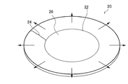
- FIG. 1 is a diagram illustrating heating of an outer portion in a method of manufacturing a glass substrate according to one embodiment.
- the glass base plate 20 is a glass plate having a substantially circular shape or a substantially elliptical shape, and has a certain plate thickness.
- the surface of the glass plate 20 is irradiated with laser light on the ring-shaped line 22 to form a defect. Further, the glass base plate 20 is heated in order to take out a portion to be a glass substrate from the glass base plate 20 on which the defect is formed. At this time, by making the heating of the outer portion 24 higher than that of the inner portion 26, the amount of thermal expansion of the outer portion 24 is made larger than the amount of thermal expansion of the inner portion 26.
- the outer portion 24 thermally expands outward as shown in FIG. For this reason, it is possible to reliably form a gap at the interface between the outer portion 24 and the inner portion 26 to form a gap. Therefore, separation of the outer portion 24 and the inner portion 26 can be ensured. Specifically, since the degree of heating of the outer part 24 is higher than that of the inner part 26, the inner diameter (inner diameter) of the outer part 24 is smaller than the outer diameter (outer diameter) of the inner part 26. A gap is formed by thermal expansion so as to be relatively large. For this reason, the outer part 24 and the inner part 26 can be reliably separated by the formed gap.
- the expression that the heating of the outer portion 24 is higher than the heating of the inner portion 26 means that the heating of the outer portion 24 and the inner portion 26 is performed with a difference in the degree of heating, and the outer portion 24 is selectively heated. , But the case where the intended heating of the inner portion 26 is not performed is also included. Even if the outer portion 24 is selectively heated, the inner portion 26 is also heated by heat conduction through the space or indirectly by heat conduction through the glass plate 20. In this case, it can be said that the heating of the outer portion 24 is higher than the heating of the inner portion 26.
- the “gap” between the inner part and the outer part to be described means that a measurable space is formed at any position between the inner part and the outer part.
- the opposing surfaces of the inner portion and the outer portion are not physically or chemically bonded. That is, the “gap” includes that a microscopic space is formed at least at a part of the boundary between the inner portion and the outer portion.
- the thermal expansion of the inner portion 26 is larger than the thermal expansion of the outer portion 24, so that the inner portion 26 moves the interface between the inner portion 26 and the outer portion 24 outward.
- the crack formed by the irradiation of the laser beam is advanced, and a new crack is generated at the interface.
- the heat of the heated inner portion 26 may be transmitted to the interface, and the formed cracks may be fixed again and may not be reliably separated.
- the heating of the outer portion 24 is increased relative to the heating of the inner portion 26 with respect to the wire 12 to ensure that the gap is formed and the separation by the cracks formed using the laser is re-bonded by heat. Can be prevented.
- Another embodiment is a method for manufacturing a glass substrate having openings.
- the manufacturing method of this glass substrate is as follows. (C) forming an inner circular portion and an outer circular portion on a surface of a glass base plate serving as a base of the glass substrate, which are irradiated with laser light substantially concentrically; (D) By heating the outer portion of the outer circumferential portion, the outer portion of the outer circumferential portion of the glass plate is thermally expanded relatively to the inner portion of the outer circumferential portion to form a gap in the outer circumferential portion; Separating the inner part of the circle and the outer part of the outer circle; (E) By heating the outer portion of the inner circumferential portion, the outer portion of the inner circumferential portion of the glass plate is relatively thermally expanded to form a gap in the inner circumferential portion, and the inner portion of the inner circumferential portion is formed. And separating the outer part of the inner circumferential part.
- FIG. 2 is a diagram illustrating heating of an outer portion in the method for manufacturing a glass substrate according to one embodiment.
- FIG. 2 illustrates that after forming the inner peripheral circular portion described in (C) above on the surface of the circular glass base plate 30, separation is performed by heating described in (E) above.
- the glass base plate 30 forms an outer circumferential portion on the surface of the glass base plate described in (C) above, and performs the steps described in (D) above to perform an inner circumferential portion and an outer circumferential portion of the outer circumferential portion.
- This is a plate that has been separated and extracted.
- the inner circumferential portion and the outer circumferential portion refer to a portion of a defect formed on the line 22.
- the shape of the outer circumferential portion described in the above (D) corresponds to the outer circumferential shape of the glass plate 30 shown in FIG.
- the outer portion 34 of the inner circumferential portion 32 formed by the irradiation of the laser beam By heating the outer portion 34 of the inner circumferential portion 32 formed by the irradiation of the laser beam, the outer portion 34 of the inner circumferential portion 32 of the glass base plate 30 is relatively thermally expanded, and a gap is formed in the inner circumferential portion 32.
- the inner portion 36 and the outer portion 34 are separated.
- the inner circle 32 corresponds to the defect formed along the line 22 in the embodiment shown in FIG.
- the outer portion of the outer circumferential portion and the inner portion is thermally expanded with respect to the inner portion, and the outer portion is heated. Since a gap is formed between the circular portion and the inner peripheral circular portion, it is possible to prevent the interface due to cracks formed by using a laser from being re-fixed by heat. Thereby, a glass substrate having openings can be efficiently formed.
- substantially concentric circles means that the amount of deviation between the center of the outer circumferential circle and the center of the inner circumferential circle is 20 ⁇ m or less, and preferably 5 ⁇ m or less.
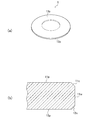
- FIG. 3A is a perspective view of an example of a magnetic disk glass substrate manufactured in one embodiment.
- FIG. 3B is a diagram showing an example of a cross section of the outer end surface of the magnetic disk glass substrate shown in FIG.
- the glass substrate 1 shown in FIG. 3A is a glass substrate for a magnetic disk.
- the glass substrate 1 is an annular thin glass substrate.
- the size of the magnetic disk glass substrate is not limited, but the magnetic disk glass substrate is, for example, the size of a magnetic disk glass substrate having a nominal diameter of 2.5 inches or 3.5 inches. In the case of a magnetic disk glass substrate having a nominal diameter of 2.5 inches, for example, the outer diameter is 65 mm, the diameter of the center hole is 20 mm to 25 mm, and the plate thickness is 0.3 to 0.8 mm.
- the outer diameter is 95 mm
- the diameter of the center hole is 20 mm to 25 mm
- the plate thickness is 0.3 to 0.8 mm.
- a magnetic layer is formed on the main surface of the glass substrate 1 to produce a magnetic disk.
- the glass substrate 1 includes a pair of main surfaces 11p and 12p, side wall surfaces 11w formed on the outer peripheral end surfaces, chamfered surfaces 11c and 12c interposed between the side wall surfaces 11w and the main surfaces 11p and 12p, and inner peripheral end surfaces. It has a side wall surface (not shown) formed similarly to the outer peripheral end surface, and a chamfered surface (not shown) interposed between the side wall surface and the main surfaces 11p and 12p.
- the glass substrate 1 has a circular hole at the center.
- the side wall surface 11w includes the center position of the glass substrate 1 in the thickness direction.
- the inclination angle of the chamfered surfaces 11c, 12c with respect to the main surfaces 11p, 12p is not particularly limited, and is, for example, 45 °.
- the boundary between the side wall surface 11w and the chamfered surfaces 11c, 12c is not limited to a shape having an edge as illustrated, but may be a smoothly continuous curved surface.
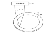
- FIG. 4 is a diagram illustrating irradiation of laser light in the glass substrate manufacturing method according to one embodiment.
- the glass plate 60 irradiated with the laser beam L shown in FIG. 4 is a glass plate having a certain thickness, which is manufactured using, for example, a floating method or a down-draw method. Alternatively, a glass plate obtained by press-molding a lump of glass using a mold may be used.
- the plate thickness of the glass base plate 60 is larger than the target plate thickness when the glass substrate for a magnetic disk, which is the final product, by a margin for grinding and polishing, for example, about several ⁇ m thicker.
- the laser light source 40 is a device that emits a laser beam L, and for example, a solid-state laser such as a YAG laser or an ND: YAG laser is used. Therefore, according to one embodiment, the wavelength of the laser beam is preferably in the range of, for example, 1030 nm to 1070 nm.
- the laser beam L is a pulsed laser. In one embodiment, the pulse width of the laser beam L is 10 ⁇ 12 seconds or less (1 picosecond or less), which indicates that the glass is excessively deteriorated at the focal position of the laser beam L. From the viewpoint that can be suppressed.
- the light energy of the laser light L can be appropriately adjusted according to the pulse width and the repetition frequency of the pulse width. If too much light energy is provided for the pulse width and repetition frequency, the glass is liable to be excessively deteriorated and residues are likely to be present at the focal position.
- the laser light source 40 divides the oscillated laser light into two light beams, and intersects the two light beams on the surface of the glass plate 60 or inside the glass plate 60.
- the laser beam L is irradiated on the glass base plate 60 while being inclined with respect to the normal direction of the main surface of the glass base plate 60.
- the light beams are formed so that the intersections of the light beams are continuous at one point on the line 62 of the glass base plate 60 along the thickness direction.
- Light energy is concentrated linearly, and a part of the glass plate 60 is turned into plasma, so that a hole or a through hole can be formed.
- the laser light L is a burst pulse that generates a plurality of light pulse groups intermittently, with a light pulse group configured to continuously generate pulsed light pulses at a fixed time interval as one unit. It is preferable to irradiate the glass base plate 60 by a method. In this case, it is also preferable to make the light energy of one pulse variable in one light pulse group.
- An example of such irradiation of the laser beam L is disclosed in Japanese Patent No. 5959597.
- the laser light L is irradiated on a line having a predetermined ring shape while being relatively moved with respect to the glass base plate 60. Thereby, a defect is formed on the line.
- a defect is formed on the line.
- an inner circumferential portion or an outer circumferential portion can be formed on the glass base plate 60.
- the laser beam L may be moved without moving the glass plate 60, or the glass plate 60 may be moved without moving the laser beam L.
- another type of laser light is further applied so that the defects are linearly continuous. It is preferred to irradiate along the line.
- a non-pulse CO 2 laser can be used as another type of laser light. With this laser light, linear defects can be formed so as to connect intermittently formed defects. That is, after the defects are intermittently formed at the discrete positions of the line 62 by irradiating the laser light L, the non-pulse CO 2 laser is used as another type of laser light to connect the intermittently formed defects. It is preferable to form a linear defect as described above to surely form a crack. Thus, the outer portion and the inner portion, which will be described later, can be reliably separated by heating.
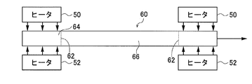
- FIG. 5 is a diagram specifically illustrating heating of the glass base plate 60 in the glass substrate manufacturing method according to one embodiment.
- the outer portion 64 is arranged in the heating space between the heaters 50 and 52 with respect to the line 62 in which the glass base plate 60 has a defect, and the inner portion 66 is positioned outside the heating space. To place. Thereby, heating of the outer portion 64 can be performed.
- the degree of heating of the outer portion 64 is higher than that of the inner portion 66, the amount of thermal expansion of the outer portion 64 can be larger than the amount of thermal expansion of the inner portion 66.
- the outer portion 64 thermally expands outward as shown in FIG. For this reason, it is possible to reliably form a gap at the interface between the outer portion 64 and the inner portion 66 and form a gap. Therefore, the separation between the outer portion 64 and the inner portion 66 can be ensured.
- the laser beam L is radiated along the ring-shaped line to form a defective portion, and then a process of heating the outer portion 64 of the line is performed.
- the laser beam L was irradiated onto the glass base plate 60 along two different substantially concentric circular arc lines to form two defect portions, the outer peripheral portion 62a and the inner peripheral portion 62b. Thereafter, the outer portion of the outer circular portion 62a can be heated, and the outer portion of the inner circular portion 62b can be heated.
- FIG. 6 is a diagram illustrating irradiation of laser light in the method for manufacturing a glass substrate according to one embodiment.
- the temperature of the outer portion 64 is higher than the inner temperature 66, and the outer portion 64 is thermally expanded relative to the inner portion 64,
- the gap along the line 62 the outer portion 64 and the inner portion 66 are separated, so that the portion to be the glass substrate can be reliably removed from the glass base plate.
- the glass substrate 1 has a ring shape having openings.
- a defect is formed by irradiating a laser beam L with a shape of an outer edge of an annular shape having an opening and a shape of a line 62 (see FIG. 4). It is preferable that the heating of the (first outer portion) be performed at a higher temperature than the inner portion 66 (first inner portion) as the first heat treatment.
- the surface roughness of the outer peripheral end surface forming the outer edge of the glass substrate 1 formed by the laser light L is smaller than that of the outer peripheral end surface mechanically cut using a conventional scriber.
- the outer portion 64 (first outer portion) and the inner portion are left as a margin for the ring shape of the glass substrate 1, leaving a length of 0.1% to 5% of the outer diameter of the ring shape.
- the portion 66 (first inner portion) is separated.
- the shape of the inner edge of the ring shape having the opening is set to the shape of the line 62, a defect is formed by irradiation with the laser beam L, and thereafter, the outer portion 64 ( It is preferable that the heating of the second outer portion) is performed as a second heating process in which the heating is higher than that of the inner portion 66 (the second inner portion).
- the surface roughness of the inner peripheral end surface forming the inner edge of the glass substrate 1 formed by the laser light L is smaller than that of the outer peripheral end surface mechanically cut using a conventional scriber.
- the inner portion 66 when performing the first heat treatment becomes the outer portion 64 when performing the second heat treatment.
- the inner portion 66 is not heated or, if heated, the degree of heating is lower than the outer portion 64.
- the temperature of the inner portion 66 is increased by heat conduction from the heated outer portion 64. Therefore, when the heated inner portion 66 is heated as the outer portion 64 in the second heat treatment, the heating time required to cause a predetermined amount of thermal expansion can be shortened.
- the glass substrate 1 can be manufactured efficiently.
- Irradiation of the glass substrate 60 with the laser light L is performed by forming a point-like through hole at a plurality of discrete points on the line by pulsed laser light, and then connecting the discrete points on the line by non-pulsed laser light.
- the irradiation position includes a continuous movement on a line.
- a crack or a potential crack is formed between adjacent through-holes among a plurality of through-holes formed by the pulsed laser light, and thereafter, the non-pulsed laser light penetrates a crack or a crack that has become apparent. Since the connection can be made between the holes, the shape processing of the glass base plate can be efficiently performed in a short time.
- the heating of the glass base plate 60 performed after the irradiation with the laser beam L includes heating the main surfaces on both sides of the glass base plate 60 by radiant heat from a heating source provided on both sides of the main surface of the glass base plate 60. Is preferred. In the heating by radiation, heat is transmitted from the main surface of the glass base plate 60 by heat conduction, and the temperature of the glass base plate 60 rises. Therefore, the interface between the outer portion 64 and the inner portion 66 is set to a temperature at which the interface is re-fixed. No. Therefore, a gap can be formed at the interface by thermal expansion of the outer portion 64.
- the area ratio of the area of the main surface of the glass base plate 60 to the area of the main surface of the glass substrate 1 is 101% to 160%, and when the outer portion 64 and the inner portion 66 are separated, one glass plate 60 It is preferable that one glass substrate 1 be extracted from the substrate.
- the difference between the plate thicknesses of the glass base plate 1 becomes large due to variation in the thickness of the glass base plate 60 depending on the location.
- the plate thickness is also made uniform, it is complicated to adjust the degree of grinding and polishing of the main surface of the glass substrate between the glass substrates.
- the laser beam irradiation can be performed accurately while rotating the glass base plate 60, and the handling of the glass base plate 60 for heating the outer portion to separate the outer portion and the inner portion is improved.
- the entire outer portion of the large glass base plate 60 is heated to increase the temperature. Therefore, when the glass plate is extracted from the heated portion, the outer portion and the inner portion are removed. Is maintained in a high state, the temperature when the outer portion is heated to a predetermined amount of thermal expansion to increase the temperature is undesirably high.
- the thickness of the glass base plate 60 is 0.6 mm or less in one embodiment.
- the glass substrate 1 manufactured from the glass base plate 60 having such a thickness can be effectively used as a glass substrate for a magnetic disk.
- the glass plate 60 having a plate thickness of 0.6 mm or less is extremely thin, and is likely to be cracked when the outer portion and the inner portion are separated by laser irradiation and heating. For this reason, the effect of the present embodiment, in which the glass substrate can be reliably separated and extracted from the glass base plate, is further increased in a thin glass base plate.
- the corners are chamfered with a different type of laser light than the laser light L.
- the laser beam is applied to the corner from a direction inclined at an angle of 30 to 60 degrees with respect to the main surface, and the corner is heated to soften and evaporate, whereby the corner can be chamfered.
- a CO 2 laser can be suitably used.
- the corner formed between the inner peripheral end face or the outer peripheral end face and the main surface can be chamfered using laser light. Since the corners are chamfered with a laser beam, the production efficiency is higher than when chamfering with a grindstone or the like. Since the end surface is not polished from the process of extracting the glass substrate of a predetermined shape from the glass base plate 60 to the chamfering of the corner of the glass substrate, the production efficiency is improved.
- the main surface of the obtained glass substrate 1 is ground and polished. In the grinding / polishing process, polishing is performed after the glass substrate 1 is ground. In the grinding process, the main surface of the glass substrate 1 is ground using a double-sided grinding device having a planetary gear mechanism. Specifically, the main surfaces on both sides of the glass substrate 1 are ground while holding the outer peripheral end surface of the glass substrate 1 in a holding hole provided in a holding member of the double-sided grinding device.
- the double-sided grinding apparatus has a pair of upper and lower platens (an upper platen and a lower platen), and the glass substrate 1 is held between the upper platen and the lower platen.
- the glass substrate 1 and each surface plate are relatively moved while supplying a coolant, so that both main surfaces of the glass substrate 1 are moved.
- a grinding member in which fixed abrasive grains in which diamond is fixed with a resin are formed in a sheet shape can be mounted on a surface plate to perform a grinding process.
- the main surface of the ground glass substrate 1 is subjected to first polishing. Specifically, the main surfaces on both sides of the glass blank are polished while holding the outer peripheral end surface of the glass substrate 1 in a holding hole provided in a polishing carrier of a double-side polishing apparatus.
- the first polishing is intended to remove scratches and distortion remaining on the main surface after the grinding process, or to adjust minute surface irregularities (micro waviness, roughness).
- the glass substrate 1 is polished while applying a polishing slurry by using a double-side polishing device having a configuration similar to that of the double-side grinding device used in the above-described grinding process using the fixed abrasive.
- a polishing slurry containing free abrasive grains is used.
- an abrasive such as cerium oxide or zirconia is used.
- the glass substrate 1 is held between a pair of upper and lower platens.
- an annular flat polishing pad for example, a resin polisher
- the size of the abrasive grains is preferably in the range of 0.5 to 3 ⁇ m in average particle diameter (D50).
- the glass substrate 1 may be chemically strengthened.
- the glass substrate 1 is immersed in the chemical strengthening liquid using, for example, a mixed melt of potassium nitrate and sodium sulfate as the chemical strengthening liquid.
- a compressive stress layer can be formed on the surface of the glass substrate 1 by ion exchange.
- the glass substrate 1 is subjected to a second polishing.
- the second polishing process aims at mirror polishing of the main surface.
- a double-side polishing apparatus having the same configuration as the double-side polishing apparatus used for the first polishing is used. More specifically, the main surfaces on both sides of the glass substrate 1 are polished while holding the outer peripheral end surface of the glass substrate 1 in a holding hole provided in a polishing carrier of a double-side polishing apparatus.
- the type and particle size of the free abrasive grains are different from the first polishing process, and the hardness of the resin polisher is different. It is preferable that the hardness of the resin polisher is smaller than that during the first polishing process.
- a polishing liquid containing colloidal silica as free abrasive grains is supplied between the polishing pad of the double-side polishing apparatus and the main surface of the glass substrate 1, and the main surface of the glass substrate 1 is polished.
- the size of the abrasive grains used for the second polishing is preferably in the range of 5 to 50 nm in average particle diameter (d50).
- the necessity of the chemical strengthening treatment may be appropriately selected in consideration of the glass composition and necessity.
- Another polishing process may be added in addition to the first polishing process and the second polishing process, and the polishing process for the two main surfaces may be completed by one polishing process. Further, the order of the above processes may be appropriately changed.
- the main surface of the glass substrate 1 is polished to obtain a magnetic disk glass substrate satisfying the conditions required for the magnetic disk glass substrate. Thereafter, at least a magnetic layer is formed on the glass substrate 1 whose main surface has been polished to produce a magnetic disk.
- the glass substrate 1 is subjected to an end surface polishing process for polishing the end surface of the glass substrate 1 before the first polishing, for example, after the first grinding, before the first polishing, or before the first grinding. Is also good. Even when such an end surface polishing process is performed, the arithmetic average roughness Ra of the end surface of the glass substrate 1 extracted from the glass base plate 60 using a laser beam is less than 0.01 ⁇ m, and the roundness is 15 ⁇ m or less. Therefore, the time required for the end face polishing process is short.
- a polishing brush method of polishing using a polishing brush while supplying free abrasive grains to the end face may be used, or a polishing method using a magnetic functional fluid may be used.
- a polishing method using a magnetic functional fluid for example, a slurry in which abrasive grains are contained in a magnetic viscous fluid is formed into a lump by a magnetic field, and the end face of the glass substrate 1 is inserted into the lump to remove the lump and the glass substrate. In this method, the end face is polished by relatively rotating.
- the end surface polishing treatment in order to increase the production efficiency, it is preferable not to perform the end surface polishing treatment.
- the roundness of the glass substrate 1 extracted from the glass base plate 60 is maintained, and the surface roughness of at least a part of the fractured surface is maintained while maintaining the surface roughness of the glass substrate 1.
- the main surface is ground or polished.
- the composition of the glass substrate 1 is not limited, but the following composition is preferable. More specifically, in terms of oxide, SiO 2 is selected from 50 to 75%, Al 2 O 3 is 1 to 15%, Li 2 O, Na 2 O and K 2 O in terms of mol%. At least one component has a total of 5 to 35%, at least one component selected from MgO, CaO, SrO, BaO and ZnO has a total of 0 to 20%, and ZrO 2 , TiO 2 and La 2 O 3 a Y 2 O 3, Ta 2 O 5, Nb 2 O 5 and 0-10% of at least one component selected from HfO 2 in total, of amorphous having a composition comprising an aluminosilicate glass.
- the glass substrate 1 is preferably, for example, in terms of mass%, SiO 2 is 57 to 75%, Al 2 O 3 is 5 to 20%, provided that the total amount of SiO 2 and Al 2 O 3 is 74%. % Or more), ZrO 2 , HfO 2 , Nb 2 O 5 , Ta 2 O 5 , La 2 O 3 , Y 2 O 3 and TiO 2 in total exceeding 0%, 6% or less, and Li 2 O at 1%.
- a composition having CaO in excess of 0% and 5% or less (however, the total amount of MgO and CaO is 5% or less, and the content of CaO is greater than the content of MgO), and 0 to 3% of SrO + BaO.
- the composition of the glass substrate 1 includes, as essential components, SiO 2 , Li 2 O, Na 2 O, and one or more alkaline earth metal oxides selected from the group consisting of MgO, CaO, SrO, and BaO.
- the molar ratio of the CaO content to the total content of CaO, SrO and BaO (CaO / (MgO + CaO + SrO + BaO) ) May be 0.20 or less and the glass transition temperature may be 650 ° C. or more.
- the glass substrate 1 having such a composition is suitable for a magnetic disk glass substrate used for a magnetic disk for energy-assisted magnetic recording.
- the method for manufacturing a glass substrate and the method for manufacturing a magnetic disk according to the present invention have been described in detail above, the method for manufacturing a glass substrate and the method for manufacturing a magnetic disk according to the present invention are not limited to the above-described embodiments, and the gist of the present invention is as follows. It goes without saying that various improvements and changes may be made without departing from the scope of the present invention.
Landscapes
- Chemical & Material Sciences (AREA)
- Engineering & Computer Science (AREA)
- Physics & Mathematics (AREA)
- Materials Engineering (AREA)
- Organic Chemistry (AREA)
- Optics & Photonics (AREA)
- Chemical Kinetics & Catalysis (AREA)
- General Chemical & Material Sciences (AREA)
- Mechanical Engineering (AREA)
- Geochemistry & Mineralogy (AREA)
- Life Sciences & Earth Sciences (AREA)
- Plasma & Fusion (AREA)
- Thermal Sciences (AREA)
- Oil, Petroleum & Natural Gas (AREA)
- Health & Medical Sciences (AREA)
- Toxicology (AREA)
- Manufacturing Of Magnetic Record Carriers (AREA)
- Laser Beam Processing (AREA)
- Re-Forming, After-Treatment, Cutting And Transporting Of Glass Products (AREA)
Priority Applications (10)
| Application Number | Priority Date | Filing Date | Title |
|---|---|---|---|
| PCT/JP2018/028269 WO2020021705A1 (ja) | 2018-07-27 | 2018-07-27 | ガラス基板の製造方法及び磁気ディスクの製造方法 |
| PCT/JP2019/029530 WO2020022510A1 (ja) | 2018-07-27 | 2019-07-26 | ガラス基板の製造方法及び磁気ディスクの製造方法 |
| MYPI2021000409A MY207144A (en) | 2018-07-27 | 2019-07-26 | Manufacturing method for glass substrate and manufacturing method for magnetic disc |
| SG11202100826TA SG11202100826TA (en) | 2018-07-27 | 2019-07-26 | Method for manufacturing glass substrate and method for manufacturing magnetic disk |
| CN201980049738.8A CN112512741B (zh) | 2018-07-27 | 2019-07-26 | 玻璃基板的制造方法以及磁盘的制造方法 |
| US17/263,019 US12084376B2 (en) | 2018-07-27 | 2019-07-26 | Method for manufacturing glass substrate and method for manufacturing magnetic disk |
| JP2020532520A JP6836694B2 (ja) | 2018-07-27 | 2019-07-26 | ガラス基板の製造方法及び磁気ディスクの製造方法 |
| JP2021017765A JP7458335B2 (ja) | 2018-07-27 | 2021-02-05 | ガラス基板の製造方法及び磁気ディスクの製造方法 |
| JP2024042075A JP7727036B2 (ja) | 2018-07-27 | 2024-03-18 | ガラス基板、ガラス基板の製造方法及び磁気ディスク用ガラス基板の製造方法 |
| US18/819,335 US20240425403A1 (en) | 2018-07-27 | 2024-08-29 | Glass substrate, method for manufacturing glass substrate, and method for manufacturing glass substrate for magnetic disk |
Applications Claiming Priority (1)
| Application Number | Priority Date | Filing Date | Title |
|---|---|---|---|
| PCT/JP2018/028269 WO2020021705A1 (ja) | 2018-07-27 | 2018-07-27 | ガラス基板の製造方法及び磁気ディスクの製造方法 |
Publications (1)
| Publication Number | Publication Date |
|---|---|
| WO2020021705A1 true WO2020021705A1 (ja) | 2020-01-30 |
Family
ID=69181399
Family Applications (2)
| Application Number | Title | Priority Date | Filing Date |
|---|---|---|---|
| PCT/JP2018/028269 WO2020021705A1 (ja) | 2018-07-27 | 2018-07-27 | ガラス基板の製造方法及び磁気ディスクの製造方法 |
| PCT/JP2019/029530 WO2020022510A1 (ja) | 2018-07-27 | 2019-07-26 | ガラス基板の製造方法及び磁気ディスクの製造方法 |
Family Applications After (1)
| Application Number | Title | Priority Date | Filing Date |
|---|---|---|---|
| PCT/JP2019/029530 WO2020022510A1 (ja) | 2018-07-27 | 2019-07-26 | ガラス基板の製造方法及び磁気ディスクの製造方法 |
Country Status (6)
Families Citing this family (4)
| Publication number | Priority date | Publication date | Assignee | Title |
|---|---|---|---|---|
| MY204661A (en) * | 2018-01-31 | 2024-09-07 | Hoya Corp | Method for producing glass substrate for magnetic disk |
| US11270724B1 (en) * | 2021-03-04 | 2022-03-08 | Western Digital Technologies, Inc. | Glass substrates for heat assisted magnetic recording (HAMR) and methods and apparatus for use with the glass substrates |
| US20240174556A1 (en) * | 2021-03-31 | 2024-05-30 | Hoya Corporation | Method for manufacturing annular glass substrate, annular glass substrate, and method for manufacturing glass substrate for magnetic disc |
| JP2024123284A (ja) * | 2021-07-05 | 2024-09-11 | Hoya株式会社 | ガラス基板の製造方法及び円盤状ガラス基板 |
Citations (4)
| Publication number | Priority date | Publication date | Assignee | Title |
|---|---|---|---|---|
| JP2014534939A (ja) * | 2011-09-21 | 2014-12-25 | レイディアンス,インコーポレイテッド | 材料を切断するシステム及び工程 |
| JP2015129076A (ja) * | 2013-11-19 | 2015-07-16 | ロフィン−ジナール テクノロジーズ インコーポレイテッド | 超高速レーザーパルスのバーストを使用して脆弱な材料基板から閉形状を取り除く方法 |
| JP2018509298A (ja) * | 2015-01-13 | 2018-04-05 | ロフィン−ジナール テクノロジーズ インコーポレイテッド | 脆性材料をスクライブして化学エッチングする方法およびシステム |
| JP2018519229A (ja) * | 2015-03-24 | 2018-07-19 | コーニング インコーポレイテッド | ディスプレイガラス組成物のレーザ切断及び加工 |
Family Cites Families (13)
| Publication number | Priority date | Publication date | Assignee | Title |
|---|---|---|---|---|
| JP2785906B2 (ja) * | 1994-02-14 | 1998-08-13 | 日本板硝子株式会社 | ガラス板の切断方法 |
| US6829910B1 (en) * | 2000-04-25 | 2004-12-14 | Asahi Glass Company, Ltd. | Removal of enclosed glass parts after cutting using heating and cooling techniques |
| JP4786783B2 (ja) | 2000-08-18 | 2011-10-05 | 日本板硝子株式会社 | ガラス板の切断方法及び記録媒体用ガラス円盤 |
| JP4225375B2 (ja) * | 2002-03-01 | 2009-02-18 | Hoya株式会社 | ガラス基板の製造方法 |
| JP5126351B2 (ja) | 2009-12-25 | 2013-01-23 | 旭硝子株式会社 | 円盤状ガラス基板及び円盤状ガラス基板の製造方法 |
| JP5574392B1 (ja) | 2012-09-28 | 2014-08-20 | Hoya株式会社 | 磁気ディスク用ガラス基板、磁気ディスク |
| JP6140047B2 (ja) * | 2013-09-30 | 2017-05-31 | Hoya株式会社 | 磁気ディスク用ガラス基板の製造方法 |
| US10017410B2 (en) | 2013-10-25 | 2018-07-10 | Rofin-Sinar Technologies Llc | Method of fabricating a glass magnetic hard drive disk platter using filamentation by burst ultrafast laser pulses |
| JP6654813B2 (ja) | 2015-06-02 | 2020-02-26 | 川崎重工業株式会社 | 面取り加工装置および面取り加工方法 |
| DE102015111490A1 (de) | 2015-07-15 | 2017-01-19 | Schott Ag | Verfahren und Vorrichtung zum lasergestützten Abtrennen eines Teilstücks von einem flächigen Glaselement |
| CN110751961B (zh) | 2015-12-28 | 2021-10-26 | Hoya株式会社 | 圆环状的玻璃坯板及制造方法、圆环状的玻璃基板的制造方法和磁盘用玻璃基板的制造方法 |
| SG11201809797PA (en) * | 2016-05-06 | 2018-12-28 | Corning Inc | Laser cutting and removal of contoured shapes from transparent substrates |
| CN110312590A (zh) | 2019-02-12 | 2019-10-08 | 大族激光科技产业集团股份有限公司 | 一种硬脆性产品的加工方法、装置以及系统 |
-
2018
- 2018-07-27 WO PCT/JP2018/028269 patent/WO2020021705A1/ja active Application Filing
-
2019
- 2019-07-26 MY MYPI2021000409A patent/MY207144A/en unknown
- 2019-07-26 US US17/263,019 patent/US12084376B2/en active Active
- 2019-07-26 SG SG11202100826TA patent/SG11202100826TA/en unknown
- 2019-07-26 WO PCT/JP2019/029530 patent/WO2020022510A1/ja active Application Filing
- 2019-07-26 CN CN201980049738.8A patent/CN112512741B/zh active Active
- 2019-07-26 JP JP2020532520A patent/JP6836694B2/ja active Active
-
2021
- 2021-02-05 JP JP2021017765A patent/JP7458335B2/ja active Active
-
2024
- 2024-03-18 JP JP2024042075A patent/JP7727036B2/ja active Active
- 2024-08-29 US US18/819,335 patent/US20240425403A1/en active Pending
Patent Citations (4)
| Publication number | Priority date | Publication date | Assignee | Title |
|---|---|---|---|---|
| JP2014534939A (ja) * | 2011-09-21 | 2014-12-25 | レイディアンス,インコーポレイテッド | 材料を切断するシステム及び工程 |
| JP2015129076A (ja) * | 2013-11-19 | 2015-07-16 | ロフィン−ジナール テクノロジーズ インコーポレイテッド | 超高速レーザーパルスのバーストを使用して脆弱な材料基板から閉形状を取り除く方法 |
| JP2018509298A (ja) * | 2015-01-13 | 2018-04-05 | ロフィン−ジナール テクノロジーズ インコーポレイテッド | 脆性材料をスクライブして化学エッチングする方法およびシステム |
| JP2018519229A (ja) * | 2015-03-24 | 2018-07-19 | コーニング インコーポレイテッド | ディスプレイガラス組成物のレーザ切断及び加工 |
Also Published As
| Publication number | Publication date |
|---|---|
| MY207144A (en) | 2025-01-31 |
| JP2024079731A (ja) | 2024-06-11 |
| CN112512741B (zh) | 2023-08-11 |
| US20240425403A1 (en) | 2024-12-26 |
| WO2020022510A1 (ja) | 2020-01-30 |
| SG11202100826TA (en) | 2021-03-30 |
| JP7458335B2 (ja) | 2024-03-29 |
| JP7727036B2 (ja) | 2025-08-20 |
| US20210230042A1 (en) | 2021-07-29 |
| JP2021075459A (ja) | 2021-05-20 |
| US12084376B2 (en) | 2024-09-10 |
| CN112512741A (zh) | 2021-03-16 |
| JP6836694B2 (ja) | 2021-03-03 |
| JPWO2020022510A1 (ja) | 2021-03-11 |
Similar Documents
| Publication | Publication Date | Title |
|---|---|---|
| JP6783401B2 (ja) | 円盤形状のガラス素板の製造方法、及び磁気ディスク用ガラス基板の製造方法 | |
| JP7411660B2 (ja) | 円環形状のガラス板の製造方法、磁気ディスク用ガラス基板の製造方法、磁気ディスクの製造方法、円環形状のガラス板、磁気ディスク用ガラス基板、及び磁気ディスク | |
| JP7458335B2 (ja) | ガラス基板の製造方法及び磁気ディスクの製造方法 | |
| JP7387927B2 (ja) | ガラス板の製造方法、ガラス板の面取り方法、および磁気ディスクの製造方法 | |
| JP7311702B2 (ja) | ガラス板および磁気ディスク | |
| JP7366141B2 (ja) | ガラス板の製造方法、磁気ディスク用ガラス基板の製造方法、および磁気ディスクの製造方法 | |
| WO2019189480A1 (ja) | ガラス基板の製造方法 | |
| US20240327280A1 (en) | Manufacturing method for glass substrate and disc-shaped glass substrate | |
| WO2022114060A1 (ja) | ガラス板の製造方法、磁気ディスク用ガラス基板の製造方法、磁気ディスクの製造方法、及び円環形状のガラス板 |
Legal Events
| Date | Code | Title | Description |
|---|---|---|---|
| 121 | Ep: the epo has been informed by wipo that ep was designated in this application |
Ref document number: 18927829 Country of ref document: EP Kind code of ref document: A1 |
|
| NENP | Non-entry into the national phase |
Ref country code: DE |
|
| 122 | Ep: pct application non-entry in european phase |
Ref document number: 18927829 Country of ref document: EP Kind code of ref document: A1 |
|
| NENP | Non-entry into the national phase |
Ref country code: JP |