WO2020021682A1 - 光散乱検出装置 - Google Patents
光散乱検出装置 Download PDFInfo
- Publication number
- WO2020021682A1 WO2020021682A1 PCT/JP2018/028124 JP2018028124W WO2020021682A1 WO 2020021682 A1 WO2020021682 A1 WO 2020021682A1 JP 2018028124 W JP2018028124 W JP 2018028124W WO 2020021682 A1 WO2020021682 A1 WO 2020021682A1
- Authority
- WO
- WIPO (PCT)
- Prior art keywords
- light
- optical system
- slit
- sample cell
- detector
- Prior art date
- Legal status (The legal status is an assumption and is not a legal conclusion. Google has not performed a legal analysis and makes no representation as to the accuracy of the status listed.)
- Ceased
Links
Images





Classifications
-
- G—PHYSICS
- G01—MEASURING; TESTING
- G01N—INVESTIGATING OR ANALYSING MATERIALS BY DETERMINING THEIR CHEMICAL OR PHYSICAL PROPERTIES
- G01N15/00—Investigating characteristics of particles; Investigating permeability, pore-volume or surface-area of porous materials
- G01N15/10—Investigating individual particles
- G01N15/14—Optical investigation techniques, e.g. flow cytometry
-
- G—PHYSICS
- G01—MEASURING; TESTING
- G01N—INVESTIGATING OR ANALYSING MATERIALS BY DETERMINING THEIR CHEMICAL OR PHYSICAL PROPERTIES
- G01N21/00—Investigating or analysing materials by the use of optical means, i.e. using sub-millimetre waves, infrared, visible or ultraviolet light
- G01N21/17—Systems in which incident light is modified in accordance with the properties of the material investigated
- G01N21/47—Scattering, i.e. diffuse reflection
- G01N21/49—Scattering, i.e. diffuse reflection within a body or fluid
Definitions
- the present invention relates to a light scattering detection device used for a particle detection device for measuring a molecular weight, a turning radius (size), and the like of fine particles dispersed in a liquid sample.
- SEC Size exclusion chromatography
- MALS multi-angle light scattering
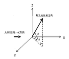
- FIG. 7 shows a coordinate system in the scattered light emission direction when a scattered light generation light source is arranged at the origin.
- light is incident on the XY plane in the positive direction of the X direction, and the scattering angle from the traveling direction of the light on the XY plane is defined as ⁇ , and the angle from the XY plane is defined as ⁇ .
- FIG. 8 is a plan view of a basic configuration example of the MALS detection device
- FIG. 9 is a side view.
- reference numeral 110 denotes a sample cell
- 111 denotes a liquid sample
- 120 denotes a light source
- 121 denotes a condenser lens
- 140 denotes a slit plate
- 150 denotes an imaging lens
- 160 denotes an aperture plate
- 170 denotes a detector.
- a liquid sample 111 is passed through a cylindrical sample cell 110, and light is emitted from a light source 120 so as to pass through the sample cell 110 and the center of the flow channel.
- a visible laser beam is used as a light source.
- the angle ⁇ from the light traveling direction is defined as the scattering angle on the horizontal plane (on the XY plane), and the detector is located on the horizontal plane (on the XY plane) passing through the sample cell 110 and the center of the channel so as to detect different scattering angles. 170 are arranged.
- FIG. 8 shows an example in which two detectors 170 are arranged at arrangement angles of ⁇ 1 and ⁇ 2.
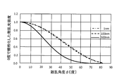
- FIGS. 10 and 11 show the relationship between the scattered light intensity and the scattering angle. That is, FIGS. 10 and 11 show the results of calculating the scattering pattern of particles having a refractive index of 1.59 in a solvent having an incident wavelength of 660 nm and a refractive index of 1.33 according to the theoretical formula of Mie scattering.
- the particle diameter was 1 nm, 100 nm, and 500 nm.
- FIG. 10 shows a scattering angle pattern in the horizontal direction ( ⁇ direction)
- FIG. 11 shows a scattering angle pattern in the vertical direction ( ⁇ direction).
- the scattered light in the ⁇ direction is generated isotropically, and the scattered light intensity does not depend on the scattering angle.
- the scattering of the scattered light in the forward direction in the direction in which ⁇ decreases
- the intensity of scattered light tends to decrease as ⁇ increases.
- a device capable of measuring a sample with a low concentration and having a high S / N ratio is desirable.
- an optical system is required that efficiently allows scattered light generated from the sample to enter the detector.
- the solid angle of the scattered light entering each detector needs to be large.
- the solid angle of the detector is increased, if the solid angle in the horizontal direction (on the optical axis plane) is increased, the angular resolution of each detector is deteriorated. Therefore, it is desirable to increase the solid angle in the vertical direction. .
- increasing the detector size to increase the solid angle is not preferable because the dark current increases.
- Non-Patent Document 1 a method of collecting scattered light with a lens or the like is adopted (Non-Patent Document 1). Specifically, the arrangement is such that scattered light generated in the cell flow path forms an image with a detector via an imaging lens. Therefore, in order to reduce the solid angle in the horizontal direction and increase the solid angle in the vertical direction, a slit having a narrow opening width in the horizontal direction and a wide opening length in the vertical direction is provided on the incident side of the imaging lens. . Thereby, scattered light can be efficiently detected without deteriorating the angular resolution.
- the present invention can set the vertical solid angle of the entrance side slit of the imaging lens to be large without setting the tilt angle ⁇ of the incident light to be large, and can measure with high S / N ratio and detection accuracy. It is an object of the present invention to provide a light scattering detection device which can perform the light scattering detection.
- a light scattering detection device is a light scattering detection device for detecting fine particles in a liquid sample, and irradiates the sample cell with a transparent sample cell holding the liquid sample and coherent light.
- a light source an imaging optical system for collecting light scattered from the sample cell to the surroundings with different scattering angles, a slit plate for limiting a range of the scattering angle incident on the imaging lens, and the imaging optics
- a detector for receiving light collected from the system, wherein a center axis of the slit is decentered in one vertical direction from a center axis of the imaging optical system.
- the slit is vertically long in a vertical direction, and at least a side along the vertical direction is straight.
- the slit is arranged eccentrically upward in the vertical direction from the center axis of the imaging optical system.
- a ⁇ b is satisfied, where a is a length below the slit in the vertical direction from the central axis of the imaging optical system, and b is an upper length.
- a plurality of detection optical systems extending from the sample cell to the detector are arranged around the sample cell at equal intervals from the cell center axis, and have a lower length a and an upper length b of the slit. It is preferable that the ratio is adjusted under the condition of a ⁇ b according to the arrangement angle of each detector with respect to the sample cell.
- the light source is arranged such that an optical axis of coherent light incident on the sample cell from the light source is inclined at a predetermined angle from a plane including the sample cell and the detector.
- the solid angle in the vertical direction of the entrance slit of the imaging lens can be set to be large without setting the tilt angle ⁇ of the incident light to be large, and the measurement is performed with high S / N ratio and high detection accuracy.
- a light scattering detection device capable of performing the light scattering.
- FIG. 2 is a partially enlarged side view of the light scattering detection device according to the embodiment. It is a top view of the light scattering detector concerning this embodiment. It is a side view for explaining arrangement and member size in ray tracing simulation.
- FIG. 1 is a partially enlarged side view of the light scattering detection device according to the embodiment. It is a top view of the light scattering detector concerning this embodiment. It is a side view for explaining arrangement and member size in ray tracing simulation.
- FIG. 14
- FIG. 3 is a plan view of a basic configuration example of the MALS detection device.
- FIG. 3 is a side view of a basic configuration example of the MALS detection device. It is explanatory drawing of the relationship (scattering angle pattern of a horizontal direction) of a scattering light intensity and a scattering angle. It is explanatory drawing of the relationship (scattering angle pattern of a perpendicular direction) of a scattering light intensity and a scattering angle.
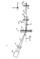
- FIG. 1 is a side view of an embodiment of the light scattering detection device according to the present invention.
- FIG. 2 is a partially enlarged side view of the light scattering detection device according to the present embodiment.
- the light scattering detection device 1 according to the present embodiment is a device that detects the molecular weight and the radius of gyration (size) of fine particles such as proteins dispersed in a liquid sample.
- the light scattering detection device 1 includes a sample cell 10, a light source 20, a slit plate 40, an imaging optical system 50, an aperture 60, and a detector 70.
- each component will be described.
- the sample cell 10 is a transparent cylindrical cell that holds a liquid sample in an internal flow path.
- the sample cell 10 is formed of, for example, colorless and transparent quartz glass.
- the light source 20 irradiates the sample cell 10 with coherent light.
- coherent light means that the phase relationship of light waves at any two points in a light beam is invariant in time and is kept constant. After splitting the light beam by an arbitrary method, a large optical path difference is given and the light beam is superimposed again. Light that shows perfect coherence even when combined.
- a laser light source for irradiating a visible light laser is employed as the light source 20. There is no perfect coherent light in the natural world, and laser light oscillating in a single mode is light close to a coherent state.
- a condensing optical system 21 is disposed on the optical path L1 of the incident light from the light source 20 to the sample cell 10.
- the condenser optical system 21 for example, a single condenser lens is employed. This condensing lens is a plano-convex lens, and the incident side of the light from the light source 20 is formed as a convex surface, and the outgoing side is formed as a flat surface.
- a single condenser lens is used as the condenser optical system 21, but the condenser optical system 21 may be configured by combining a plurality of compound lenses or condenser mirrors.
- the light source 20 and the condensing optical system 21 are arranged such that the optical axis of the coherent light incident on the sample cell 10 from the light source 20 is at a predetermined angle (tilt angle ⁇ ) from a plane (XY plane) including the sample cell 10 and the detector 50. It is arranged to be inclined. Specifically, the light source 20 and the condensing optical system 21 are arranged so that the incident light enters the sample cell 10 from obliquely above. By tilting the incident light with respect to the sample cell 10 (angle ⁇ ), the interface between the glass and the air and the interface between the glass and the flow path of the sample cell 10 (hereinafter collectively referred to as “cell interface”). Stray light due to reflected light can be reduced.
- the laser light emitted from the light source 20 passes through the focusing optical system 21 and is focused near the central axis of the sample cell 10.
- a detection optical system 30 is disposed on the optical path L2 of the light emitted from the sample cell 10.
- the detection optical system 30 of the present embodiment includes a slit plate 40, an imaging optical system 50, an aperture plate 60, and a detector 70.
- the imaging optical system 50 collects light scattered from the sample cell 10 to the surroundings at different scattering angles.
- a single imaging lens is employed as the imaging optical system 50.
- This imaging lens is a plano-convex lens, and the incident side of the scattered light from the sample cell 10 is formed as a plane, and the emission side is formed as a convex surface.
- a single imaging lens is employed as the imaging optical system 50, but the imaging optical system 50 may be configured by combining a plurality of compound lenses or imaging mirrors.
- the slit plate 40 is arranged between the sample cell 10 and the imaging optical system 50 on the optical path L2 of the light emitted from the sample cell 10.
- the slit plate 40 limits the scattering angle range incident on the imaging optical system 50. That is, the slit 41 opened in the slit plate 40 limits the scattering angle in the horizontal direction, and in order to take in a large amount of light flux in the vertical direction, the slit 41 is vertically long in the vertical direction, and at least the side along the vertical direction is formed. It is straight.
- the slit 41 has a vertically long rectangular shape or a long hole shape in the vertical direction.
- the central axis 41S of the slit 41 is eccentrically arranged in the vertical direction from the central axis 50S of the imaging optical system 50. Since the irradiation light of the light source 20 is incident obliquely from above the sample cell 10, the reflected light RL generated at the interface between the air and the glass and the interface between the glass and the liquid (hereinafter, “cell interface”) of the sample cell 10. Are easily deflected downward as stray light. Therefore, the central axis 41S of the slit 41 of the present embodiment is eccentrically arranged vertically upward from the central axis 50S of the imaging optical system 50 in order to limit the reflected light (stray light) RL.
- the lower length of the slit 41 is The relationship between the height a and the upper length b is set so that a ⁇ b.
- the incident light may be incident upward from below, in which case the relationship between the lower length a and the upper length b of the slit 41 is set so that a> b.
- the aperture plate 60 is arranged on the optical path L2 of the light emitted from the sample cell 10 on the imaging optical system side with respect to the detector 70.
- the aperture plate 60 has a function of restricting stray light, and the aperture 61 is open in front of the light receiving surface of the detector 70.
- the detector 70 receives the condensed light from the imaging optical system 50. That is, the light receiving surface of the detector 70 is located at the focal point of the imaging optical system 50.
- a photodiode PD
- an array detector such as a two-dimensional CMOS may be employed.
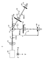
- FIG. 3 is a plan view of one embodiment of the light scattering detection device according to the present embodiment.
- a plurality of detection optical systems 30 from the sample cell 10 to the detector 70 are arranged around the sample cell 10 at equal intervals d from the cell center axis S.
- the angle ⁇ from the traveling direction of light is defined as a scattering angle on a horizontal plane (on an XY plane).
- a plurality of detectors 70 are arranged on a horizontal plane (XY plane) passing through the sample cell 10 and the cell center axis S so that different scattering angles can be detected.
- two detection optical systems 30 and 31 are arranged at arrangement angles of ⁇ 1 and ⁇ 2.
- the liquid sample 11 is passed through the flow path of the cylindrical sample cell 10.
- visible light which is coherent light
- the visible laser light travels along the optical path L1 so that the laser light is incident on the liquid sample 11 in the flow path of the sample cell 10.
- the laser light hits the fine particles included in the liquid sample 11 and is scattered at a predetermined scattering angle.
- the scattered light emitted from the sample cell 10 passes through the slit 41 of the slit plate 40, passes through the imaging optical system 50 and the aperture plate 60, and is received on the light receiving surface of the detector 70.
- the reflected light RL is generated as stray light at the cell interface of the sample cell 10. Since the irradiation light from the light source 20 is incident on the sample cell 10 at a tilt angle ⁇ from above, the reflected light (stray light) generated at the cell interface of the sample cell 10 tends to be deflected downward. Since the slit 41 of the present embodiment is eccentrically arranged vertically upward from the central axis 50S of the imaging optical system 50, the reflected light (stray light) RL deflected downward at the plate portion of the slit plate 40 is limited. be able to.
- the imaging optical system 40 forms an image on a light receiving surface of the detector 60, and an aperture plate 50 is disposed in front of the light receiving surface. Therefore, the aperture plate 50 further limits the stray light, and the scattered light required for the analysis can be received on the light receiving surface of the detector 70.
- the lower length of the slit 41 in the vertical direction from the central axis 50S of the imaging optical system 50 is a and the upper length is b
- the lower length a and the upper length b of the slit 41 are Are set such that a ⁇ b. That is, by setting the length a in the downward direction of the slit 41 small, the reflected light RL at the cell interface can be blocked by the plate portion of the slit plate 40.
- the solid angle in the vertical direction can be increased by setting the length b in the upward direction to be large with the effective diameter of the imaging optical system 50 as an upper limit.
- a plurality of detection optical systems 30 from the sample cell 10 to the detector 70 are arranged at equal intervals d from the cell center axis S.
- FIG. 4 is a side view for explaining the arrangement and the member dimensions in the ray tracing simulation.
- FIG. 6 is a side view thereof.
- the sample cell 10 is, for example, a transparent cylindrical cell having an inner diameter of 1.6 mm and an outer diameter of 8.0 mm.
- An imaging lens (plano-convex lens) is arranged at a position 47 mm from the central axis S of the sample cell 10.
- the imaging lens has, for example, a convex diameter of 12.7 mm and a focal length of 38 mm.
- An aperture plate 60 and a 2.4 mm PD are arranged at a position 140 mm from the central axis S of the sample cell 10.
- the slit 41 of the slit plate 40 is formed as, for example, an opening having a width in the horizontal direction (XY direction) of 3 mm and a length in the vertical direction (Z direction) of 8.5 mm.
- the vertical opening of the slit 41 for example, the lower length a from the XY plane including the central axis 50S of the imaging optical system 50 is 2.5 mm in the -Z direction, and the upper length b is 6 mm in the + Z direction. 0.0 mm.
- the reflected light RL generated at the cell interface of the sample cell 10 is Since the light is blocked by the portion and does not reach the detector 70, accurate measurement is possible.
- ⁇ Stray light due to reflected light RL at the cell interface depends on the arrangement angle ⁇ of the detector 70.
- ⁇ is small, the influence of the reflected light RL at the cell interface is large, so a needs to be shortened.
- ⁇ is close to 90 degrees, the reflected light RL at the cell interface hardly occurs.
- the slit 31 of the slit plate 30 disposed on the incident side of the imaging optical system 40 can be set without setting the tilt angle ⁇ of the incident light large. It is possible to provide a light scattering detection device which can set a large solid angle in the vertical direction and can measure at a high S / N ratio with high detection accuracy.
Landscapes
- Chemical & Material Sciences (AREA)
- Physics & Mathematics (AREA)
- Health & Medical Sciences (AREA)
- Life Sciences & Earth Sciences (AREA)
- Analytical Chemistry (AREA)
- Biochemistry (AREA)
- General Health & Medical Sciences (AREA)
- General Physics & Mathematics (AREA)
- Immunology (AREA)
- Pathology (AREA)
- Dispersion Chemistry (AREA)
- Investigating Or Analysing Materials By Optical Means (AREA)
Abstract
【課題】入射光のチルト角度αを大きく設定することなく、結像レンズの入射側スリットの鉛直方向の立体角を大きく設定することができ、高いS/N比で検出精度よく測定することができる光散乱検出装置を提供する。 【解決手段】光散乱検出装置1は、液体試料を保持する透明な試料セル10と、試料セル10にコヒーレント光を照射する光源20と、試料セル10から周囲に異なる散乱角を以て散乱する光を集光する結像光学系50と、結像光学系50に入射する散乱角範囲を制限するためのスリット板40と、結像光学系50からの集光を受光する検出器70と、を備え、スリット41の中心軸41Sは、結像光学系50の中心軸50Sから鉛直方向一方へ偏心して配置されている。
Description
本発明は、液体試料中に分散している微粒子の分子量や回転半径(サイズ)等を測定するための微粒子検出装置に利用される光散乱検出装置に関する。
液体試料中に分散しているタンパク質等の微粒子を分離するための手法として、サイズ排除クロマトグラフィ(SEC)が知られている。近年、クロマトグラフィ検出装置としては、紫外線(UV)吸光度検出装置や示差屈折率検出装置に加え、多角度光散乱(MALS)検出装置が用いられている。MALS検出装置は、測定試料の分子量や粒子径が算出可能であるという特長がある(特許文献1および2参照)。
図7は、原点に散乱光発生光源を配置した場合の散乱光放射方向の座標系を示している。図7に示すように、XY面上においてX方向正方向に光が入射し、XY面上における光の進行方向からの散乱角度をθ、XY面上からの角度をφと定義する。
次に、図8は、MALS検出装置の基本構成例の平面図を、図9は側面図を示している。図8および図9において、110は試料セル、111は液体試料、120は光源、121は集光レンズ、140はスリット板、150は結像レンズ、160はアパーチャ板、170は検出器である。図8および図9に示すように、円筒体状の試料セル110の内部に液体試料111を通液し、試料セル110および流路中心を通るように光源120から光を照射する。光源としては、通常、可視レーザ光が用いられる。光の進行方向からの角度θが水平面上(XY平面上)の散乱角として定義され、異なる散乱角を検出するように試料セル110および流路中心を通る水平面上(XY平面上)に検出器170が複数配置される。図8は、θ1,θ2の配置角度で検出器170を2個配置した例である。
円筒体状の試料セル110の場合、ガラスと空気との界面及びガラスと流路との界面における反射光が迷光として検出器170に入り、検出器170の検出精度を悪化させるという課題があった。その解決策として、発明者は、図9に示すように、試料セル110に対して入射光をチルト(角度α)させることによって、上記迷光を低減させる手法を見出した(非特許文献1参照)。
次に、図10および図11は、散乱光強度と散乱角の関係を示している。すなわち、図10及び図11は、Mie散乱の理論式に従って、入射波長660nm、屈折率1.33の溶媒中での屈折率1.59の粒子の散乱パターンを計算した結果である。粒子径は、1nm、100nm、500nmとした。図10は水平方向(θ方向)の散乱角度パターンであり、図11は鉛直方向(φ方向)の散乱角度パターンである。試料が入射光の波長に比べて十分小さい場合、θ方向への散乱光は等方的に発生し、散乱光強度の散乱角依存性はない。試料の粒子径が大きくなるに従い、散乱光は前方(θが小さい方向)への散乱が強くなる。φ方向には、φが大きくなるに従い、散乱光強度が小さくなる傾向がある。
また、MALS検出装置では、低い濃度の試料が測定でき、かつ、高いS/N比の装置が望ましい。そのためには、試料から発生する散乱光を効率的に検出器に入るようにする光学系が求められる。言い換えると、各検出器に入る散乱光の立体角が大きい必要がある。検出器の立体角を大きくする際に、水平方向(光軸面上)の立体角を大きくすると、各検出器の角度分解能が悪くなってしまうため、鉛直方向の立体角を大きく取ることが望ましい。ただし、立体角を大きくすべく検出器サイズを大きくすることは、暗電流が増加するため、好ましくない。
検出器サイズを大きくすることなく、立体角を大きく取るためには、レンズ等で散乱光を集光する方法が採られる(非特許文献1)。具体的には、セル流路で発生した散乱光が結像レンズを介して、検出器で結像する配置である。そこで、水平方向の立体角を小さくし、鉛直方向の立体角を大きくするために、結像レンズの入射側に、水平方向の開口幅が狭く、鉛直方向に広い開口長を有するスリットが設けられる。これにより、角度分解能が悪化することなく、散乱光を効率的に検出することができる。
検出器に入る光量を増加させるためには、結像レンズの入射側に配置されたスリットの鉛直方向の開口長を大きく設定する必要がある。しかし、スリットの鉛直方向の開口長を大きく設定すると、試料セルのガラスと空気との界面及びガラスと流路との界面での反射光が、迷光として検出器に入射される。反射光は散乱光に比べて強度が大きいため、検出器のダイナミックレンジが低下するとともに、迷光の強度変動により検出器の検出精度が悪化する。一方、この迷光を除去するために、入射光のチルト角度αを大きく設定すると、図11に示したように鉛直方向の散乱角度φが大きくなり、スリットに入る散乱光強度が低下し、S/N比が低下する。
そこで、本発明は、入射光のチルト角度αを大きく設定することなく、結像レンズの入射側スリットの鉛直方向の立体角を大きく設定することができ、高いS/N比で検出精度よく測定することができる光散乱検出装置を提供することを目的とする。
本発明の一態様に係る光散乱検出装置は、液体試料中の微粒子を検出するための光散乱検出装置であって、液体試料を保持する透明な試料セルと、上記試料セルにコヒーレント光を照射する光源と、上記試料セルから周囲に異なる散乱角を以て散乱する光を集光する結像光学系と、上記結像レンズに入射する散乱角範囲を制限するためのスリット板と、上記結像光学系からの集光を受光する検出器と、を備え、上記スリットの中心軸は、上記結像光学系の中心軸から鉛直方向一方へ偏心して配置されていることを特徴とする。
上記光散乱検出装置の構成において、上記スリットは、鉛直方向に縦長であって、少なくとも鉛直方向に沿った辺が直状であることが好ましい。
また、上記スリットは、上記結像光学系の中心軸から鉛直方向の上方へ偏心して配置されていることが好ましい。
さらに、上記スリットの上記結像光学系の中心軸からの鉛直方向の下方長さをa、上方長さをbとした場合に、a<bの関係を有することが好ましい。
そして、上記試料セルから上記検出器に至る検出光学系は、上記試料セルの周囲にセル中心軸から等間隔で複数配されており、上記スリットの下方長さaと上方長さbとの長さ比は、上記試料セルに対する各検出器の配置角度に応じて、a≦bの条件下で調整されることが好ましい。
加えて、上記光源は、該光源から上記試料セルに入射するコヒーレント光の光軸が、上記試料セル及び上記検出器を含む平面から所定の角度傾斜するように配置されている、ことが好ましい。
本発明によれば、入射光のチルト角度αを大きく設定することなく、結像レンズの入射側スリットの鉛直方向の立体角を大きく設定することができ、高いS/N比で検出精度よく測定することができる光散乱検出装置を提供することができる。
以下、本発明に係る光散乱検出装置の一実施形態について図面を参照して説明する。なお、各図において、同一の符号を付したものは、同一又は同様の構成を有する。
〔光散乱検出装置の構成〕
まず、図1から図3を参照して、本発明に係る光散乱検出装置の一実施形態の構成について説明する。図1は、本発明に係る光散乱検出装置の一実施形態の側面図である。図2は、本実施形態に係る光散乱検出装置の一部拡大側面図である。図1および図2に示すように、本実施形態に係る光散乱検出装置1は、液体試料中に分散しているタンパク質等の微粒子の分子量や回転半径(サイズ)を検出する装置である。光散乱検出装置1は、試料セル10、光源20、スリット板40、結像光学系50、アパーチャ60および検出器70を備える。以下、各構成要素ごとに説明する。
まず、図1から図3を参照して、本発明に係る光散乱検出装置の一実施形態の構成について説明する。図1は、本発明に係る光散乱検出装置の一実施形態の側面図である。図2は、本実施形態に係る光散乱検出装置の一部拡大側面図である。図1および図2に示すように、本実施形態に係る光散乱検出装置1は、液体試料中に分散しているタンパク質等の微粒子の分子量や回転半径(サイズ)を検出する装置である。光散乱検出装置1は、試料セル10、光源20、スリット板40、結像光学系50、アパーチャ60および検出器70を備える。以下、各構成要素ごとに説明する。
試料セル10は、内部の流路に液体試料を保持する透明な円筒体状のセルである。試料セル10は、例えば、無色透明な石英ガラスによって形成されている。
光源20は、試料セル10にコヒーレント光を照射する。「コヒーレント光」とは、光束内の任意の2点における光波の位相関係が時間的に不変で一定に保たれており、任意の方法で光束を分割した後、大きな光路差を与えて再び重ね合わせても完全な干渉性を示す光をいう。光源20としては、例えば、可視光レーザを照射するためのレーザ光源が採用される。自然界には完全なコヒーレント光は存在せず、シングルモードで発振するレーザ光はコヒーレント状態に近い光である。
光源20から試料セル10に至る入射光の光路L1には、集光光学系21が配置されている。集光光学系21としては、例えば、単一の集光レンズが採用されている。この集光レンズは、平凸レンズであり、光源20からの光の入射側が凸面で、出射側が平面に形成されている。本実施形態では、集光光学系21として、単一の集光レンズを採用しているが、集光光学系21は複数の複合レンズや集光ミラーを組み合わせて構成してもよい。
光源20および集光光学系21は、光源20から試料セル10に入射するコヒーレント光の光軸が、試料セル10及び検出器50を含む平面(XY平面)から所定の角度(チルト角度α)で傾斜するように配置されている。具体的には、試料セル10に対して入射光が斜め上方から入射するように、光源20および集光光学系21が配置されている。試料セル10に対して入射光をチルト(角度α)させることによって、試料セル10のガラスと空気との界面及びガラスと流路との界面(以下、「セル界面」と総称する。)での反射光による迷光を低減させることができる。光源20から照射されたレーザ光は、集光光学系21を通過した後、試料セル10の中心軸付近に集光する。
試料セル10からの出射光の光路L2上には、検出光学系30が配置されている。本実施形態の検出光学系30は、スリット板40、結像光学系50、アパーチャ板60及び検出器70から構成されている。
結像光学系50は、試料セル10から周囲に異なる散乱角を以て散乱する光を集光する。結像光学系50としては、例えば、単一の結像レンズが採用されている。この結像レンズは、平凸レンズであり、試料セル10からの散乱光の入射側が平面で、出射側が凸面に形成されている。本実施形態では、結像光学系50として、単一の結像レンズを採用したが、結像光学系50は複数の複合レンズや結像ミラーを組み合わせて構成してもよい。
スリット板40は、試料セル10からの出射光の光路L2上において、試料セル10と結像光学系50との間に配置されている。スリット板40は、結像光学系50に入射する散乱角範囲を制限する。すなわち、スリット板40に開口されたスリット41は、水平方向の散乱角を制限し、且つ、鉛直方向の光束を多く取り込むために、鉛直方向に縦長であって、少なくとも鉛直方向に沿った辺が直状である。具体的には、スリット41は、鉛直方向に縦長の長方形状や長孔形状を呈している。
スリット41の中心軸41Sは、結像光学系50の中心軸50Sから鉛直方向一方へ偏心して配置されている。光源20の照射光が試料セル10の斜め上方から入射するため、試料セル10の空気とガラスとの界面およびガラスと液体との界面(以下、「セル界面」という。)で生じた反射光RLが迷光として下方へ偏り易い。したがって、本実施形態のスリット41の中心軸41Sは、反射光(迷光)RLを制限すべく、結像光学系50の中心軸50Sから鉛直方向の上方へ偏心して配置されている。
具体的には、図2に示すように、スリット41の結像光学系50の中心軸50Sからの鉛直方向の下方長さをa、上方長さをbとした場合に、スリット41の下方長さaと上方長さbの関係はa<bとなるように設定される。入射光は下方から上方へ入射してもよく、その場合は、スリット41の下方長さaと上方長さbとの関係はa>bとなるように設定される。
アパーチャ板60は、試料セル10からの出射光の光路L2上において、検出器70よりも結像光学系側に配置されている。アパーチャ板60は迷光を制限する機能を有し、アパーチャ61は検出器70の受光面前で開口している。
検出器70は、結像光学系50からの集光を受光する。すなわち、結像光学系50の焦点に、検出器70の受光面が位置している。本実施形態の検出器70としては、例えば、フォトダイオード(PD)を採用しているが、2次元CMOS等のアレイ検出器を採用してもよい。
図3は、本実施形態に係る光散乱検出装置の一実施形態の平面図である。図3に示すように、試料セル10から検出器70に至る検出光学系30は、試料セル10の周囲にセル中心軸Sから等間隔dで複数配されている。光の進行方向からの角度θが水平面上(XY平面上)の散乱角として定義される。異なる散乱角を検出できるように、試料セル10およびセル中心軸Sを通る水平面上(XY平面上)に検出器70が複数配置される。図3の態様では、θ1,θ2の配置角度で検出光学系30、31が2系配置されている。
試料セル10の周囲に等間隔dで複数の検出器70を備える場合、試料セル10に対する各検出器70の配置角度に応じて、スリット41の下方長さaと上方長さbとの長さ比は、a≦bの条件下で調整される。すなわち、図3において、散乱角θ2に配置した検出光学系31は、散乱角θ1に配置した検出光学系30よりも、セル界面での反射光の影響が少ない。散乱角θ2=90度の検出光学系31は、セル界面での反射光の影響が少ないので、aを大きく設定して、bに近づけることで、鉛直方向の立体角を最適化することができる。
〔光散乱検出装置の作用〕
次に、図1から図6を参照して、本実施形態に係る光散乱検出装置の作用について説明する。
次に、図1から図6を参照して、本実施形態に係る光散乱検出装置の作用について説明する。
図1および図2に示すように、円筒体状の試料セル10の流路に液体試料11が通液される。液体試料11の通液が完了すると、光源20から集光光学系21を介してコヒーレント光である可視レーザ光が照射される。可視レーザ光は、光路L1に沿って進むことにより、レーザ光が試料セル10の流路内の液体試料11に入射する。液体試料11にレーザ光が入射されると、その光は液体試料11に含まれる微粒子に当たって所定の散乱角を以て散乱する。そして、試料セル10から出射した散乱光は、スリット板40のスリット41を通過した後、結像光学系50およびアパーチャ板60を経て、検出器70の受光面上に受光される。
試料セル10から散乱光が出射する際、試料セル10のセル界面において、反射光RLが迷光として生じる。光源20の照射光が試料セル10の斜め上方からチルト角度αで入射するため、試料セル10のセル界面で生じた反射光(迷光)は下方へ偏り易い。本実施形態のスリット41は、結像光学系50の中心軸50Sから鉛直方向の上方へ偏心配置されているので、スリット板40の板部分で下方へ偏った反射光(迷光)RLを制限することができる。
このようにスリット板30のスリット31を結像光学系40の中心軸40Sから鉛直方向の上方へ偏心配置したことにより、分析に有益な散乱光を積極的に結像光学系40へ入射させることができる。結像光学系40は、検出器60の受光面に結像するが、受光面前にアパーチャ板50が配置されている。したがって、アパーチャ板50がさらに迷光を制限し、分析に必要な散乱光を検出器70の受光面に受光させることができる。
具体的には、スリット41の結像光学系50の中心軸50Sからの鉛直方向の下方長さをa、上方長さをbとした場合に、スリット41の下方長さaと上方長さbの関係はa<bとなるように設定される。すなわち、スリット41の下方向長さaを小さく設定することにより、セル界面での反射光RLをスリット板40の板部分で遮断することができる。上方向長さbについては、結像光学系50の有効径を上限として大きく設定することで、鉛直方向の立体角を大きくすることができる。
また、図3に示すように、試料セル10の周囲には、試料セル10から検出器70に至る検出光学系30がセル中心軸Sから等間隔dで複数配されている。光散乱検出装置1が試料セル10の周囲に等間隔dで複数の検出光学系30を備える場合に、スリット41の下方長さaと上方長さbとの長さ比は、試料セル10に対する各検出器70の配置角度に応じて、a≦bの条件下で調整される。すなわち、セル界面での反射光RLの影響が少ない散乱角θ2=90度に配置した検出光学系31では、aを大きく設定し、bに近づけることで、鉛直方向の立体角を最適化することができる。
〔光線追跡シミュレーション〕
上記実施形態の作用効果を確認すべく、光線追跡シミュレーションを実施した。図4は、光線追跡シミュレーションにおける配置および部材寸法を説明するための側面図である。図5は、検出器(PD)をθ=15度に配置した場合における光線追跡シミュレーションの結果を説明するための平面図、図6はその側面図である。
上記実施形態の作用効果を確認すべく、光線追跡シミュレーションを実施した。図4は、光線追跡シミュレーションにおける配置および部材寸法を説明するための側面図である。図5は、検出器(PD)をθ=15度に配置した場合における光線追跡シミュレーションの結果を説明するための平面図、図6はその側面図である。
図4に示すように、試料セル10は、例えば、内径が1.6mmで、外径が8.0mmの透明な円筒体状のセルである。試料セル10の中心軸Sから47mmの位置には、結像レンズ(平凸レンズ)が配置されている。結像レンズは、例えば、凸径がφ12.7mmで、焦点距離が38mmに形成されている。試料セル10の中心軸Sから140mmの位置には、アパーチャ板60および2.4mmのPDが配置されている。スリット板40のスリット41は、例えば、水平方向(XY方向)幅が3mmで、鉛直方向(Z方向)長さ8.5mmの開口として形成されている。スリット41の鉛直方向開口については、例えば、結像光学系50の中心軸50Sを含むXY平面からの下方長さaが-Z方向に2.5mmで、上方向長さbが+Z方向に6.0mmに設定されている。
図5および図6に示すように、下方長さaと上方長さbとの関係をa<bに設定することにより、試料セル10のセル界面で生じた反射光RLがスリット板41の板部分により遮断されて検出器70に到達しないため、精度良い測定が可能である。
また、セル界面での反射光RLによる迷光は、検出器70の配置角度θに依存する。θが小さい場合には、セル界面での反射光RLの影響が大きいため、aは短くする必要があるが、θが90度に近い場合にはセル界面での反射光RLは殆ど生じない。検出器70の配置角度に応じて、a≦bの条件の下でスリット41を最適化することで、迷光の低減とS/N比の向上を実現することができる。
以上説明したように、本実施形態の光散乱検出装置1によれば、入射光のチルト角度αを大きく設定することなく、結像光学系40の入射側に配置したスリット板30のスリット31の鉛直方向の立体角を大きく設定することができ、高いS/N比で検出精度よく測定することができる光散乱検出装置を提供することができる。
上記の実施形態は、本発明の理解を容易にするためのものであり、本発明を限定して解釈するためのものではない。実施形態が備える各要素並びにその配置、材料、条件、形状及びサイズ等は、例示したものに限定されるわけではなく適宜変更することができる。また、異なる実施形態で示した構成同士を部分的に置換し又は組み合わせることが可能である。
1…光散乱検出装置
10…試料セル
20…光源
30…検出光学系
40…スリット板
41…スリット
41S…スリットの中心軸
50…結像光学系
51S…結像光学系の中心軸
70…検出器
10…試料セル
20…光源
30…検出光学系
40…スリット板
41…スリット
41S…スリットの中心軸
50…結像光学系
51S…結像光学系の中心軸
70…検出器
Claims (6)
- 液体試料中の微粒子を検出するための光散乱検出装置であって、
液体試料を保持する透明な試料セルと、
前記試料セルにコヒーレント光を照射する光源と、
前記試料セルから周囲に異なる散乱角を以て散乱する光を集光する結像光学系と、
前記結像光学系に入射する散乱角範囲を制限するためのスリット板と、
前記結像光学系からの集光を受光する検出器と、
を備え、
前記スリットの中心軸は、前記結像光学系の中心軸から鉛直方向一方へ偏心して配置されていることを特徴とする光散乱検出装置。 - 前記スリットは、鉛直方向に縦長であって、少なくとも鉛直方向に沿った辺が直状である、請求項1に記載の光散乱検出装置。
- 前記スリットは、前記結像光学系の中心軸から鉛直方向の上方へ偏心して配置されている、請求項1または請求項2に記載の光散乱検出装置。
- 前記スリットの前記結像光学系の中心軸からの鉛直方向の下方長さをa、上方長さをbとした場合に、a<bの関係を有する、請求項3に記載の光散乱検出装置。
- 前記試料セルから前記検出器に至る検出光学系は、前記試料セルの周囲にセル中心軸から等間隔で複数配されており、
前記スリットの下方長さaと上方長さbとの長さ比は、前記試料セルに対する各検出器の配置角度に応じて、a≦bの条件下で調整される、請求項4に記載の光散乱検出装置。 - 前記光源は、該光源から前記試料セルに入射するコヒーレント光の光軸が、前記試料セル及び前記検出器を含む平面から所定の角度傾斜するように配置されている、請求項1から5のいずれか1項に記載の光散乱検出装置。
Priority Applications (3)
| Application Number | Priority Date | Filing Date | Title |
|---|---|---|---|
| CN201880095864.2A CN112469985B (zh) | 2018-07-26 | 2018-07-26 | 光散射检测装置 |
| PCT/JP2018/028124 WO2020021682A1 (ja) | 2018-07-26 | 2018-07-26 | 光散乱検出装置 |
| JP2020532094A JP7078115B2 (ja) | 2018-07-26 | 2018-07-26 | 光散乱検出装置 |
Applications Claiming Priority (1)
| Application Number | Priority Date | Filing Date | Title |
|---|---|---|---|
| PCT/JP2018/028124 WO2020021682A1 (ja) | 2018-07-26 | 2018-07-26 | 光散乱検出装置 |
Publications (1)
| Publication Number | Publication Date |
|---|---|
| WO2020021682A1 true WO2020021682A1 (ja) | 2020-01-30 |
Family
ID=69180957
Family Applications (1)
| Application Number | Title | Priority Date | Filing Date |
|---|---|---|---|
| PCT/JP2018/028124 Ceased WO2020021682A1 (ja) | 2018-07-26 | 2018-07-26 | 光散乱検出装置 |
Country Status (3)
| Country | Link |
|---|---|
| JP (1) | JP7078115B2 (ja) |
| CN (1) | CN112469985B (ja) |
| WO (1) | WO2020021682A1 (ja) |
Families Citing this family (1)
| Publication number | Priority date | Publication date | Assignee | Title |
|---|---|---|---|---|
| WO2010110323A1 (ja) | 2009-03-26 | 2010-09-30 | 日本ゼオン株式会社 | 重合体、水素添加物、樹脂組成物、樹脂膜及び電子部品 |
Citations (5)
| Publication number | Priority date | Publication date | Assignee | Title |
|---|---|---|---|---|
| JPS60243565A (ja) * | 1984-05-17 | 1985-12-03 | Toa Medical Electronics Co Ltd | 体液成分分析方法およびその装置 |
| JPS6138447A (ja) * | 1984-07-28 | 1986-02-24 | Canon Inc | 粒子解析装置 |
| JPH0255936A (ja) * | 1988-08-19 | 1990-02-26 | Nippon Kagaku Kogyo Kk | 光散乱式計測装置 |
| JPH0277636A (ja) * | 1988-09-13 | 1990-03-16 | Canon Inc | 粒子測定装置 |
| JP2009156669A (ja) * | 2007-12-26 | 2009-07-16 | Nippon Telegr & Teleph Corp <Ntt> | 浮遊粒子状物質測定装置 |
Family Cites Families (16)
| Publication number | Priority date | Publication date | Assignee | Title |
|---|---|---|---|---|
| CN85200108U (zh) * | 1985-04-01 | 1985-09-10 | 北京大学 | 喇曼光谱样品架 |
| JPS6370148A (ja) * | 1986-09-11 | 1988-03-30 | Shimadzu Corp | 微細粒度分布測定装置 |
| US5104221A (en) * | 1989-03-03 | 1992-04-14 | Coulter Electronics Of New England, Inc. | Particle size analysis utilizing polarization intensity differential scattering |
| JP3106521B2 (ja) * | 1991-03-06 | 2000-11-06 | 株式会社ニコン | 透明基板の光学的検査装置 |
| JP2552940Y2 (ja) * | 1992-07-18 | 1997-11-05 | 株式会社堀場製作所 | 微粒子測定装置 |
| JP3415475B2 (ja) * | 1999-04-16 | 2003-06-09 | 株式会社堀場製作所 | 粒子径分布測定装置 |
| JP2006145374A (ja) * | 2004-11-19 | 2006-06-08 | Konica Minolta Sensing Inc | 反射特性測定装置及びマルチアングル測色計 |
| JP4817356B2 (ja) * | 2005-03-15 | 2011-11-16 | ナノフォトン株式会社 | 光学顕微鏡 |
| JP2008039539A (ja) * | 2006-08-04 | 2008-02-21 | Shimadzu Corp | 光散乱検出装置 |
| US7847936B2 (en) * | 2007-05-15 | 2010-12-07 | Waters Technologies Corporation | Evaporative light scattering device and methods of use thereof |
| CN101236128B (zh) * | 2008-02-04 | 2013-05-08 | 杭州浙大三色仪器有限公司 | 分布光度计 |
| CN102159934A (zh) * | 2008-09-26 | 2011-08-17 | 株式会社堀场制作所 | 颗粒物性测量装置 |
| CN103063691B (zh) * | 2011-10-18 | 2014-11-12 | 北京睿思厚德辐射信息科技开发有限公司 | 双飞线多缝扫描背散射平面成像立体成像和自扫描成像装置 |
| CN104849212B (zh) * | 2014-02-19 | 2019-04-23 | 中国科学院上海高等研究院 | 针孔装置及针孔调节方法 |
| JP6202684B2 (ja) * | 2014-06-05 | 2017-09-27 | 株式会社リガク | X線回折装置 |
| CN106525772B (zh) * | 2016-12-20 | 2023-06-09 | 上海众毅工业控制技术有限公司 | 一种高精度超低量程在线浊度传感器及其浊度测量方法 |
-
2018
- 2018-07-26 CN CN201880095864.2A patent/CN112469985B/zh active Active
- 2018-07-26 WO PCT/JP2018/028124 patent/WO2020021682A1/ja not_active Ceased
- 2018-07-26 JP JP2020532094A patent/JP7078115B2/ja active Active
Patent Citations (5)
| Publication number | Priority date | Publication date | Assignee | Title |
|---|---|---|---|---|
| JPS60243565A (ja) * | 1984-05-17 | 1985-12-03 | Toa Medical Electronics Co Ltd | 体液成分分析方法およびその装置 |
| JPS6138447A (ja) * | 1984-07-28 | 1986-02-24 | Canon Inc | 粒子解析装置 |
| JPH0255936A (ja) * | 1988-08-19 | 1990-02-26 | Nippon Kagaku Kogyo Kk | 光散乱式計測装置 |
| JPH0277636A (ja) * | 1988-09-13 | 1990-03-16 | Canon Inc | 粒子測定装置 |
| JP2009156669A (ja) * | 2007-12-26 | 2009-07-16 | Nippon Telegr & Teleph Corp <Ntt> | 浮遊粒子状物質測定装置 |
Also Published As
| Publication number | Publication date |
|---|---|
| JPWO2020021682A1 (ja) | 2021-04-30 |
| CN112469985B (zh) | 2024-12-10 |
| JP7078115B2 (ja) | 2022-05-31 |
| CN112469985A (zh) | 2021-03-09 |
Similar Documents
| Publication | Publication Date | Title |
|---|---|---|
| US8576396B2 (en) | Cell construction for light scatter detectors having self-focusing properties | |
| EP3593110B1 (en) | Particle characterisation with a focus tuneable lens | |
| CN108291863B (zh) | 用于使用光散射技术进行个体颗粒尺寸测量的系统和方法 | |
| JP4817442B2 (ja) | 粒子分析装置用光学系、及びそれを用いた粒子分析装置 | |
| RU2006108798A (ru) | Оптический расходомер для измерения расхода газов и жидкостей в трубопроводах | |
| JP4594206B2 (ja) | 屈折率示差を測定するための向上された示差屈折計および測定方法 | |
| WO2020026704A1 (ja) | 光散乱検出装置 | |
| CN112304864B (zh) | 光散射检测装置以及光散射检测方法 | |
| CN206074449U (zh) | 一种用于荧光分析仪的光斑整形光学系统 | |
| JP7078115B2 (ja) | 光散乱検出装置 | |
| CN212059104U (zh) | 一种宽光谱高灵敏度拉曼光谱仪 | |
| JP7187874B2 (ja) | 光散乱検出装置 | |
| WO2020026378A1 (ja) | 光散乱検出装置および光散乱検出方法 | |
| JP6583525B2 (ja) | 顕微分析装置 | |
| JP3106521B2 (ja) | 透明基板の光学的検査装置 | |
| CN216117256U (zh) | 一种基于运动光学测试的线型光斑光路结构 | |
| JPH0136109Y2 (ja) | ||
| JP7052925B2 (ja) | 光散乱検出装置 | |
| JP6992699B2 (ja) | 光散乱検出装置 | |
| WO2019202648A1 (ja) | 光散乱検出装置 | |
| JP7070797B2 (ja) | 光散乱検出装置 | |
| US20220244163A1 (en) | Light scattering detection apparatus | |
| JP2017207336A (ja) | 粒子検出装置及び粒子検出装置の検査方法 |
Legal Events
| Date | Code | Title | Description |
|---|---|---|---|
| 121 | Ep: the epo has been informed by wipo that ep was designated in this application |
Ref document number: 18927522 Country of ref document: EP Kind code of ref document: A1 |
|
| ENP | Entry into the national phase |
Ref document number: 2020532094 Country of ref document: JP Kind code of ref document: A |
|
| NENP | Non-entry into the national phase |
Ref country code: DE |
|
| 122 | Ep: pct application non-entry in european phase |
Ref document number: 18927522 Country of ref document: EP Kind code of ref document: A1 |