WO2020021612A1 - 金属接合構造体および金属接合構造体の製造方法 - Google Patents
金属接合構造体および金属接合構造体の製造方法 Download PDFInfo
- Publication number
- WO2020021612A1 WO2020021612A1 PCT/JP2018/027598 JP2018027598W WO2020021612A1 WO 2020021612 A1 WO2020021612 A1 WO 2020021612A1 JP 2018027598 W JP2018027598 W JP 2018027598W WO 2020021612 A1 WO2020021612 A1 WO 2020021612A1
- Authority
- WO
- WIPO (PCT)
- Prior art keywords
- alloy member
- phase
- layer
- alloy
- solid solution
- Prior art date
- Legal status (The legal status is an assumption and is not a legal conclusion. Google has not performed a legal analysis and makes no representation as to the accuracy of the status listed.)
- Ceased
Links
Images

Classifications
-
- B—PERFORMING OPERATIONS; TRANSPORTING
- B23—MACHINE TOOLS; METAL-WORKING NOT OTHERWISE PROVIDED FOR
- B23K—SOLDERING OR UNSOLDERING; WELDING; CLADDING OR PLATING BY SOLDERING OR WELDING; CUTTING BY APPLYING HEAT LOCALLY, e.g. FLAME CUTTING; WORKING BY LASER BEAM
- B23K26/00—Working by laser beam, e.g. welding, cutting or boring
- B23K26/20—Bonding
- B23K26/21—Bonding by welding
- B23K26/211—Bonding by welding with interposition of special material to facilitate connection of the parts
-
- B—PERFORMING OPERATIONS; TRANSPORTING
- B23—MACHINE TOOLS; METAL-WORKING NOT OTHERWISE PROVIDED FOR
- B23K—SOLDERING OR UNSOLDERING; WELDING; CLADDING OR PLATING BY SOLDERING OR WELDING; CUTTING BY APPLYING HEAT LOCALLY, e.g. FLAME CUTTING; WORKING BY LASER BEAM
- B23K26/00—Working by laser beam, e.g. welding, cutting or boring
- B23K26/20—Bonding
- B23K26/21—Bonding by welding
- B23K26/24—Seam welding
-
- B—PERFORMING OPERATIONS; TRANSPORTING
- B23—MACHINE TOOLS; METAL-WORKING NOT OTHERWISE PROVIDED FOR
- B23K—SOLDERING OR UNSOLDERING; WELDING; CLADDING OR PLATING BY SOLDERING OR WELDING; CUTTING BY APPLYING HEAT LOCALLY, e.g. FLAME CUTTING; WORKING BY LASER BEAM
- B23K26/00—Working by laser beam, e.g. welding, cutting or boring
- B23K26/20—Bonding
- B23K26/21—Bonding by welding
- B23K26/24—Seam welding
- B23K26/244—Overlap seam welding
-
- B—PERFORMING OPERATIONS; TRANSPORTING
- B23—MACHINE TOOLS; METAL-WORKING NOT OTHERWISE PROVIDED FOR
- B23K—SOLDERING OR UNSOLDERING; WELDING; CLADDING OR PLATING BY SOLDERING OR WELDING; CUTTING BY APPLYING HEAT LOCALLY, e.g. FLAME CUTTING; WORKING BY LASER BEAM
- B23K26/00—Working by laser beam, e.g. welding, cutting or boring
- B23K26/20—Bonding
- B23K26/21—Bonding by welding
- B23K26/24—Seam welding
- B23K26/26—Seam welding of rectilinear seams
-
- B—PERFORMING OPERATIONS; TRANSPORTING
- B23—MACHINE TOOLS; METAL-WORKING NOT OTHERWISE PROVIDED FOR
- B23K—SOLDERING OR UNSOLDERING; WELDING; CLADDING OR PLATING BY SOLDERING OR WELDING; CUTTING BY APPLYING HEAT LOCALLY, e.g. FLAME CUTTING; WORKING BY LASER BEAM
- B23K26/00—Working by laser beam, e.g. welding, cutting or boring
- B23K26/20—Bonding
- B23K26/32—Bonding taking account of the properties of the material involved
- B23K26/322—Bonding taking account of the properties of the material involved involving coated metal parts
-
- B—PERFORMING OPERATIONS; TRANSPORTING
- B23—MACHINE TOOLS; METAL-WORKING NOT OTHERWISE PROVIDED FOR
- B23K—SOLDERING OR UNSOLDERING; WELDING; CLADDING OR PLATING BY SOLDERING OR WELDING; CUTTING BY APPLYING HEAT LOCALLY, e.g. FLAME CUTTING; WORKING BY LASER BEAM
- B23K26/00—Working by laser beam, e.g. welding, cutting or boring
- B23K26/20—Bonding
- B23K26/32—Bonding taking account of the properties of the material involved
- B23K26/323—Bonding taking account of the properties of the material involved involving parts made of dissimilar metallic material
-
- B—PERFORMING OPERATIONS; TRANSPORTING
- B23—MACHINE TOOLS; METAL-WORKING NOT OTHERWISE PROVIDED FOR
- B23K—SOLDERING OR UNSOLDERING; WELDING; CLADDING OR PLATING BY SOLDERING OR WELDING; CUTTING BY APPLYING HEAT LOCALLY, e.g. FLAME CUTTING; WORKING BY LASER BEAM
- B23K2101/00—Articles made by soldering, welding or cutting
- B23K2101/006—Vehicles
-
- B—PERFORMING OPERATIONS; TRANSPORTING
- B23—MACHINE TOOLS; METAL-WORKING NOT OTHERWISE PROVIDED FOR
- B23K—SOLDERING OR UNSOLDERING; WELDING; CLADDING OR PLATING BY SOLDERING OR WELDING; CUTTING BY APPLYING HEAT LOCALLY, e.g. FLAME CUTTING; WORKING BY LASER BEAM
- B23K2101/00—Articles made by soldering, welding or cutting
- B23K2101/18—Sheet panels
-
- B—PERFORMING OPERATIONS; TRANSPORTING
- B23—MACHINE TOOLS; METAL-WORKING NOT OTHERWISE PROVIDED FOR
- B23K—SOLDERING OR UNSOLDERING; WELDING; CLADDING OR PLATING BY SOLDERING OR WELDING; CUTTING BY APPLYING HEAT LOCALLY, e.g. FLAME CUTTING; WORKING BY LASER BEAM
- B23K2101/00—Articles made by soldering, welding or cutting
- B23K2101/34—Coated articles ; Surface treated articles
-
- B—PERFORMING OPERATIONS; TRANSPORTING
- B23—MACHINE TOOLS; METAL-WORKING NOT OTHERWISE PROVIDED FOR
- B23K—SOLDERING OR UNSOLDERING; WELDING; CLADDING OR PLATING BY SOLDERING OR WELDING; CUTTING BY APPLYING HEAT LOCALLY, e.g. FLAME CUTTING; WORKING BY LASER BEAM
- B23K2103/00—Materials to be soldered, welded or cut
- B23K2103/18—Dissimilar materials
- B23K2103/20—Ferrous alloys and aluminium or alloys thereof
Definitions
- the present invention relates to a metal joined structure in which alloy members having different melting points are welded to each other, and a method of manufacturing the metal joined structure.
- a joined body in which alloy members having different melting points are joined to each other is used.
- an Al alloy member having a small specific gravity is used for weight reduction, while an Fe alloy member is used for realizing high rigidity. For this reason, a portion where the Fe alloy member and the Al alloy member are integrated by welding occurs.
- Patent Document 1 discloses a method for manufacturing a dissimilar material welded structure that is a metal-joined structure in which an Al material or an Al alloy material and steel that is a type of Fe alloy are joined.
- the dissimilar material welded structure disclosed in Patent Literature 1 is manufactured using a dissimilar material joining filler material containing Si and Ti, with the balance being Al and an Al alloy that is an unavoidable impurity.
- the dissimilar material welded structure described in Patent Literature 1 is formed by welding and joining a dissimilar material joining material containing Al and an Al alloy between steel, which is a kind of Fe alloy, and an Al alloy.
- the Al component contained in the dissimilar material joining additive reacts with the Fe alloy to form a joining interface layer. Therefore, there is a concern that a fragile Fe-Al intermetallic compound is formed in the bonding interface layer, and there is a concern that the joint efficiency may be reduced. there were.
- the present invention has been made to solve the above-described problems, and provides a metal bonding structure having improved bonding strength and a method of manufacturing the metal bonding structure in welding of an Fe alloy and an Al alloy. Main purpose.
- a metal bonded structure according to the present invention is provided with an Fe alloy member, an Al alloy member, and provided between the Fe alloy member and the Al alloy member. Having a Fe-Si solid solution phase in contact with the aluminum alloy, an Al-Si eutectic phase in contact with the Al alloy member, and a Si phase provided between the Fe-Si solid solution phase and the Al-Si eutectic phase An interface layer is provided.
- an Fe alloy is provided between a Fe alloy member and an Al alloy member by including a bonding interface layer including a Si phase composed of a simple substance of Si having a lower melting point than the Fe alloy and a higher melting point than the Al alloy.
- a bonding interface layer including a Si phase composed of a simple substance of Si having a lower melting point than the Fe alloy and a higher melting point than the Al alloy.
- Al alloy can be suppressed from melting, and the joining strength can be improved.
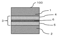
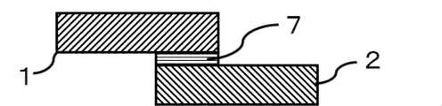
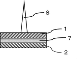
- Sectional view of a metal bonding structure according to the first embodiment The figure which shows the specific example of the joining interface layer of the metal joining structure shown in FIG. State explanatory view before production of a metal bonded structure Explanatory drawing of the joining method of the metal joining structure
- FIG. 1 is a cross-sectional view of the metal joint structure according to the present embodiment.
- the metal bonding structure 100 includes an Fe alloy member 1, an Al alloy member 2, and a bonding interface layer 3 provided between the Fe alloy member and the Al alloy member.
- the Fe alloy member 1 and the Al alloy constituting the Al alloy member 2 are not particularly limited, but the Fe alloy member 1 includes, for example, SPCC (cold-rolled low carbon steel), For example, JIS A1000-based (pure Al-based), A2000-based (Al-Cu-based alloy), A3000-based (Al-Mn-based alloy), A4000 series (Al-Si alloy), A5000 series (Al-Mg alloy), A6000 series (Al-Mg-Si alloy), A7000 series (Al-Zn-Mg alloy) and the like can be used. .
- SPCC cold-rolled low carbon steel
- FIG. 2 is a diagram showing a specific example of the bonding interface layer shown in FIG.
- the structure of the bonding interface layer 3 of the metal bonding structure 100 according to the present embodiment will be described with reference to FIG.
- the bonding interface layer 3 is composed of a Fe-Si solid solution phase 4, an Al-Si eutectic phase 5, and a Si phase 6 formed between the Fe-Si solid solution phase 4 and the Al-Si eutectic phase 5. Is done.
- the Si phase 6 is a phase of Si that does not completely melt the Si layer 7 and does not melt with other metals. Incidentally, Si has a lower melting point than Fe and a higher melting point than Al.
- the solid solution phase refers to a phase in which another element is partially substituted or penetrated while maintaining the original crystal, and the eutectic phase is composed of two or more elements. This is a phase in which crystals to be mixed and crystals having a different component ratio are mixed uniformly.
- the Fe-Si solid solution phase 4 is a phase in which Si particles are dissolved in the Fe matrix, and the bonding strength is improved by solid solution strengthening.
- the Al-Si eutectic phase 5 is a phase in which Si particles are dispersed in an Al matrix, and the bonding strength is improved by solid solution strengthening.
- solid solution strengthening using a solid solution containing a different element the lattice constant changes but the crystal structure does not change from the matrix.
- the Fe—Al intermetallic compound formed by crystallization has a crystal structure different from that of the matrix, has poor consistency with the matrix, and is coarse and difficult to disperse. Therefore, it tends to be a starting point of crack generation in the metal joint structure.
- the metal bonded structure 100 has the Fe—Si solid solution phase 4, the Al—Si eutectic phase 5, and the Si phase 6 between the Fe alloy member 1 and the Al alloy member 2, and thus the Fe alloy member 1 and the Al alloy member 2 are significantly improved in bonding strength. Since the interface of the Si particles in the Al-Si eutectic phase 5 has low compatibility with the Fe matrix or the Al matrix, it is desirable that the Si particle size be small in order to improve the bonding strength.
- the structure of the bonding interface layer 3 according to the present embodiment has been described by taking as an example a combination of a Fe-Si solid solution phase, a Si phase, and an Al-Si eutectic phase. It is needless to say that the same effect can be obtained even if a combination of the Al-Si solid solution phase or the combination of the Fe-Si eutectic phase, the Si phase and the Al-Si eutectic phase is used.
- FIG. 4 shows a portion where the Fe alloy member 1 and the Al alloy member 2 on which a Si layer 7 described later is formed are overlapped.
- the Fe alloy member 1 Fe melting point: 1538 ° C.
- the Al alloy member 2 Al melting point: 660 ° C.
- the Si layer 7 Si melting point: 1414 ° C.
- SPCC cold-rolled steel plate
- A6063 is used for the Al alloy constituting the Al alloy member 2.
- a YAG laser is used as a light source of the high energy beam 8.
- an Si film is provided on the surface to be joined of the Al alloy member 2 by a cold spray method, and an Si layer 7 is formed.
- the Si constituting the Si layer 7 is preferably of high purity, and desirably 95 to 99.99 wt%.
- the Si layer 7 is formed on the bonding surface of the Al alloy member 2 to a thickness of 1.0 ⁇ m by cold spraying using 99.99 wt% Si powder.
- the cold spray method is a technique in which a powder material is made to collide with a substrate in a solid state at a melting temperature or lower without melting or gasifying the powder material to form a film.
- the Al layer 2 having a lower melting point than the Si layer 7 is not melted, and the Si layer 7 can be formed with good uniformity.
- Al 2 O 3 film a strong oxide film exists on the surface of the Al alloy member 2, and this oxide film hinders welding. As a result, the oxide film is destroyed, and the Si layer 7 can be formed on the surface of the Al alloy member 2 from which the oxide film has been removed.
- a high energy beam 8 is applied to the center of the part.
- the irradiation conditions of the high-energy beam 8 include a spot diameter ⁇ at the irradiation point of the high-energy beam 8, a laser output, and an irradiation so that the temperature distribution is such that only the Si layer 7 is melted without melting the Al alloy member 2. The time is set.
- an Fe alloy member 1 having an area of 80 mm ⁇ 20 mm and a plate thickness of 0.5 mm
- an Al alloy member 2 having an area of 80 mm ⁇ 20 mm and a plate thickness of 1.0 mm and having a Si layer 7 formed thereon.
- the spot diameter ⁇ of the irradiation point of the high-energy beam 8 in the Fe alloy member 1 is 6 mm.
- the high energy beam 8 is defocused and irradiated with a laser output of 1 kW for an irradiation time of 2 seconds.
- argon gas is ejected from a nozzle (not shown) coaxially arranged with the laser at a flow rate of 20 L / min to shield.
- the phase 6 and the Fe alloy member 1 are firmly joined via the Fe—Si solid solution phase 4.
- the Fe—Si solid solution phase 4 and the Al—Si eutectic phase 5 are sequentially formed by the interdiffusion of Fe and Si, and Al and Si, so that the thickness increases as compared with the Si layer 7, and as a result, In addition, the thickness of the bonding interface layer 3 also increases.
- the irradiation of the high energy beam 8 is adjusted so as to heat at a temperature higher than the melting point of the Si layer 7 and lower than the melting point of the Fe alloy member 1.
- the high energy beam 8 is irradiated from the lower surface side of the Al alloy member 2, the Al alloy member 2 is completely melted first and the Fe alloy member 1 does not melt, so that the two cannot be joined.
- a metal bonded structure 100 as shown in FIG. 1 can be obtained.
- the present embodiment has been described by taking a YAG laser as an example of the light source of the high-energy beam 8, but the light source for such an application is not limited to only the YAG laser, but may be a CO2 laser, a fiber laser, a disk laser, or the like. Alternatively, a semiconductor laser or the like may be used.
- the bonding method of the present embodiment does not require plating, so that it can be easily applied to a material that is difficult to be plated, and as a result, the plating step can be omitted.
- the joint efficiency of the metal joint structure 100 obtained by the above-described joining method was evaluated together with the comparative example.
- the joint efficiency is a value indicating the strength of the welded joint with respect to the strength of the base material.
- the thickness of the bonding interface layer 3 was mirror-finished by mechanical polishing, a sample for observation of the cross section of the bonding surface was prepared, and the measurement was performed using a scanning electron microscope (SEM).
- the joint efficiency was calculated from the tensile shear strength measured by performing a tensile test using a metal bonded structure. The evaluation was evaluated as ⁇ when the joint efficiency was 80% or more, ⁇ when the joint efficiency was 80% or more and less than 80%, and X when the joint efficiency was less than 60%. Table 1 summarizes Examples and Comparative Examples.
- the thickness of the Si layer 7 be 1.0 to 300 ⁇ m from the viewpoint of joint efficiency in order to melt the Si layer 7 to form a phase of a simple substance of Si.
- the reason that the Si layer 7 preferably has a thickness of 1.0 to 300 ⁇ m is that Fe diffuses into Al when the thickness is less than 1.0 ⁇ m, but peels off when the thickness is more than 300 ⁇ m. This is because a failure occurs.
- Comparative Example 1 since the Si layer 7 is thin and the Al alloy member 2 is melted during welding, a solid solution phase, a Si phase, and a eutectic phase are not formed in the bonding interface layer, and the coarse Fe—Al A poor intermetallic compound was formed, and the joint efficiency deteriorated.
- Comparative Example 2 since the Si layer 7 was too thick, a large amount of heat was required for melting, and the Si layer 7 was overheated, and the surface layers of the Fe alloy member 1 and the Al alloy member 2 were melted. However, a coarse intermetallic compound of Fe—Al was formed, and the bonding strength between the bonding interface layer 3 and the Fe alloy member 1 and the Al alloy member 2 was reduced. As a result, the joint efficiency deteriorated.
- the joint efficiency is good. It is difficult to stably form the bonding interface layer 3 having a thickness of less than 1.0 ⁇ m while maintaining uniformity. This is because it is difficult to form the stable bonding interface layer 3 itself.
- the metal bonded structure according to the present embodiment shown in FIG. 1 is obtained.
- the presence of Si phase 6 formed by melting of Si layer 7 itself causes Fe alloy member 1 to flow into Al—Si eutectic phase 5 side and Al alloy member 2 can be prevented from flowing into the Fe-Si solid solution phase 4 side. Therefore, since the Fe alloy member 1 and the Al alloy member 2 can be prevented from directly melting and forming a coarse Fe—Al intermetallic compound, the bonding strength between the Fe alloy member 1 and the Al alloy member 2 can be suppressed. The effect of improving is produced.
- a member used for a chassis, a body, and a frame is partially applied with an Al alloy member lighter than an Fe alloy member. And lightening can be realized.
Landscapes
- Physics & Mathematics (AREA)
- Optics & Photonics (AREA)
- Engineering & Computer Science (AREA)
- Plasma & Fusion (AREA)
- Mechanical Engineering (AREA)
- Pressure Welding/Diffusion-Bonding (AREA)
- Laser Beam Processing (AREA)
Abstract
Description
図1は、本実施の形態に係る金属接合構造体の断面図である。金属接合構造体100は、Fe合金部材1と、Al合金部材2と、Fe合金部材とAl合金部材の間に設けられた接合界面層3とで構成される。
高エネルギービーム8照射中は、レーザと同軸配置した図示しないノズルから、アルゴンガスを20L/minの流量で噴出させてシールドする。
接合界面層3の厚さに関しては、機械研磨で鏡面仕上げを行い、接合面の断面観察用サンプルを用意し、SEM(走査型電子顕微鏡)を用いて測定を行った。

すなわち、比較例1では、Si層7が薄く、溶接時にAl合金部材2が溶融してしまうため、接合界面層に固溶相、Si相、共晶相が形成されず、Fe-Alの粗大な金属間化合物が形成してしまい、継手効率が悪化した。一方、比較例2は、Si層7が厚すぎたため、溶融するために大量の熱量が必要となり、Si層7を加熱しすぎてしまい、Fe合金部材1およびAl合金部材2の表層がそれぞれ溶融し、Fe-Alの粗大な金属間化合物が形成してしまい、接合界面層3とFe合金部材1およびAl合金部材2間のそれぞれの接合強度が小さくなってしまう結果、継手効率が悪化した。
5 Al-Si共晶相、 6 Si相、 7 Si層、8 高エネルギービーム、
100 金属接合構造体。
Claims (5)
- Fe合金部材と、
Al合金部材と、
前記Fe合金部材と前記Al合金部材の間に設けられ、前記Fe合金部材に接するFe-Si固溶相と、前記Al合金部材に接するAl-Si共晶相と、前記Fe-Si固溶相と前記Al-Si共晶相との間に設けられたSi相と、を有する接合界面層と、
を備える金属接合構造体。 - 前記接合界面層の厚さが1.0~360μmであることを特徴とする請求項1に記載の金属接合構造体。
- Al合金部材の被接合面に、Si層を形成する工程と、
Fe合金部材を、前記Si層を介して前記Al合金部材に重ね合わせる工程と、
前記Fe合金部材側に高エネルギービームを照射して前記Fe合金部材を加熱して、前記Fe合金部材側からの熱伝導によって生じる、前記Fe合金部材と前記Si層との接合面の融解によるFe-Si固溶相の形成、前記Al合金部材と前記Si層との接合面の融解によるAl-Si共晶相の形成、および、前記Si層の融解によるSi相の形成によって、前記Fe合金部材と前記Al合金部材とを接合させる工程と、
を含む金属接合構造体の製造方法。 - 前記Si層の厚さが1.0~300μmであることを特徴とする請求項3に記載の金属接合構造体の製造方法。
- 前記Si層は、コールドスプレー法によって前記Al合金部材の被接合面にSiの皮膜を成膜することにより形成される、請求項3または4に記載の金属接合構造体の製造方法。
Priority Applications (4)
| Application Number | Priority Date | Filing Date | Title |
|---|---|---|---|
| PCT/JP2018/027598 WO2020021612A1 (ja) | 2018-07-24 | 2018-07-24 | 金属接合構造体および金属接合構造体の製造方法 |
| DE112018007755.1T DE112018007755B4 (de) | 2018-07-24 | 2018-07-24 | Metallverbindungsstruktur und Verfahren zur Herstellung einer Metallverbindungsstruktur |
| US17/257,863 US11173570B2 (en) | 2018-07-24 | 2018-07-24 | Metal-joining structure and method for manufacturing metal-joining structure |
| JP2018562690A JP6512382B1 (ja) | 2018-07-24 | 2018-07-24 | 金属接合構造体および金属接合構造体の製造方法 |
Applications Claiming Priority (1)
| Application Number | Priority Date | Filing Date | Title |
|---|---|---|---|
| PCT/JP2018/027598 WO2020021612A1 (ja) | 2018-07-24 | 2018-07-24 | 金属接合構造体および金属接合構造体の製造方法 |
Publications (1)
| Publication Number | Publication Date |
|---|---|
| WO2020021612A1 true WO2020021612A1 (ja) | 2020-01-30 |
Family
ID=66530724
Family Applications (1)
| Application Number | Title | Priority Date | Filing Date |
|---|---|---|---|
| PCT/JP2018/027598 Ceased WO2020021612A1 (ja) | 2018-07-24 | 2018-07-24 | 金属接合構造体および金属接合構造体の製造方法 |
Country Status (4)
| Country | Link |
|---|---|
| US (1) | US11173570B2 (ja) |
| JP (1) | JP6512382B1 (ja) |
| DE (1) | DE112018007755B4 (ja) |
| WO (1) | WO2020021612A1 (ja) |
Families Citing this family (4)
| Publication number | Priority date | Publication date | Assignee | Title |
|---|---|---|---|---|
| CN114340833B (zh) * | 2019-08-27 | 2024-03-19 | 株式会社神户制钢所 | 异种材料接合结构体的制造方法和异种材料接合结构体 |
| JP7319231B2 (ja) * | 2020-07-08 | 2023-08-01 | 株式会社神戸製鋼所 | 異材接合構造体の製造方法 |
| JP7231586B2 (ja) * | 2020-07-17 | 2023-03-01 | 株式会社神戸製鋼所 | 異材接合構造体の製造方法 |
| DE102021111205A1 (de) | 2021-04-30 | 2022-11-03 | Bayerische Motoren Werke Aktiengesellschaft | Verfahren zum Fügen von Bauteilen sowie Bauteilverbindung |
Citations (7)
| Publication number | Priority date | Publication date | Assignee | Title |
|---|---|---|---|---|
| JPS6199585A (ja) * | 1984-06-01 | 1986-05-17 | Hitachi Ltd | アルミニウムメツキ鋼板の接合構造と接合方法 |
| JPH10262363A (ja) * | 1997-03-18 | 1998-09-29 | Sumitomo Light Metal Ind Ltd | リニアモーターカー用リアクションプレートおよびその製造方法 |
| JP2008105087A (ja) * | 2006-10-27 | 2008-05-08 | Honda Motor Co Ltd | 鉄部材とアルミニウム部材の接合方法及び鉄−アルミニウム接合体 |
| JP2008260967A (ja) * | 2007-04-10 | 2008-10-30 | Nippon Steel Corp | 接合部の耐食性に優れた自動車用部材 |
| JP2010042422A (ja) * | 2008-08-11 | 2010-02-25 | Nisshin Steel Co Ltd | 鋼材とアルミニウム材料のろう付け接合構造およびろう付け方法 |
| JP2013091089A (ja) * | 2011-10-27 | 2013-05-16 | Honda Motor Co Ltd | 金属部材の接合方法 |
| US20180036840A1 (en) * | 2016-08-04 | 2018-02-08 | Honda Motor Co., Ltd. | Multi-material component and methods of making thereof |
Family Cites Families (12)
| Publication number | Priority date | Publication date | Assignee | Title |
|---|---|---|---|---|
| US7475478B2 (en) * | 2001-06-29 | 2009-01-13 | Kva, Inc. | Method for manufacturing automotive structural members |
| JP2006105087A (ja) | 2004-10-08 | 2006-04-20 | Mitsubishi Heavy Ind Ltd | 蒸気タービン及び蒸気タービン運転方法 |
| US20080031768A1 (en) * | 2006-08-04 | 2008-02-07 | Salvador Valtierra-Gallardo | Wear-resistant aluminum alloy for casting engine blocks with linerless cylinders |
| JP2009061500A (ja) * | 2007-08-10 | 2009-03-26 | Nissan Motor Co Ltd | 異種金属接合部材及び異種金属接合方法 |
| EP2614916A1 (en) * | 2008-04-21 | 2013-07-17 | Honda Motor Co., Ltd. | Method for joining metallic members and brazing filler metal |
| JP5237231B2 (ja) | 2008-09-29 | 2013-07-17 | 本田技研工業株式会社 | ろう材、金属部材の接合構造、および、金属部材の接合方法 |
| JP5689492B2 (ja) | 2013-03-19 | 2015-03-25 | 株式会社神戸製鋼所 | 異材接合用溶加材及び異材溶接構造体の製造方法 |
| US9987705B2 (en) * | 2013-06-07 | 2018-06-05 | GM Global Technology Operations LLC | Resistance spot welding of steel to pre-coated aluminum |
| EP3068574B1 (en) * | 2013-11-14 | 2018-02-28 | The Welding Institute | Method of welding first and second metallic workpiece with cold spraying a layer of weld modifying material to one of the surfaces |
| US20150352659A1 (en) * | 2014-06-10 | 2015-12-10 | GM Global Technology Operations LLC | Cover plate with intruding feature to improve al-steel spot welding |
| US10625367B2 (en) * | 2016-04-08 | 2020-04-21 | GM Global Technology Operations LLC | Method of resistance spot welding aluminum to steel |
| US20170297137A1 (en) * | 2016-04-19 | 2017-10-19 | GM Global Technology Operations LLC | Method of joining aluminum and steel workpieces |
-
2018
- 2018-07-24 WO PCT/JP2018/027598 patent/WO2020021612A1/ja not_active Ceased
- 2018-07-24 DE DE112018007755.1T patent/DE112018007755B4/de active Active
- 2018-07-24 US US17/257,863 patent/US11173570B2/en active Active
- 2018-07-24 JP JP2018562690A patent/JP6512382B1/ja active Active
Patent Citations (7)
| Publication number | Priority date | Publication date | Assignee | Title |
|---|---|---|---|---|
| JPS6199585A (ja) * | 1984-06-01 | 1986-05-17 | Hitachi Ltd | アルミニウムメツキ鋼板の接合構造と接合方法 |
| JPH10262363A (ja) * | 1997-03-18 | 1998-09-29 | Sumitomo Light Metal Ind Ltd | リニアモーターカー用リアクションプレートおよびその製造方法 |
| JP2008105087A (ja) * | 2006-10-27 | 2008-05-08 | Honda Motor Co Ltd | 鉄部材とアルミニウム部材の接合方法及び鉄−アルミニウム接合体 |
| JP2008260967A (ja) * | 2007-04-10 | 2008-10-30 | Nippon Steel Corp | 接合部の耐食性に優れた自動車用部材 |
| JP2010042422A (ja) * | 2008-08-11 | 2010-02-25 | Nisshin Steel Co Ltd | 鋼材とアルミニウム材料のろう付け接合構造およびろう付け方法 |
| JP2013091089A (ja) * | 2011-10-27 | 2013-05-16 | Honda Motor Co Ltd | 金属部材の接合方法 |
| US20180036840A1 (en) * | 2016-08-04 | 2018-02-08 | Honda Motor Co., Ltd. | Multi-material component and methods of making thereof |
Also Published As
| Publication number | Publication date |
|---|---|
| DE112018007755T5 (de) | 2021-03-11 |
| US20210245301A1 (en) | 2021-08-12 |
| JPWO2020021612A1 (ja) | 2020-08-06 |
| US11173570B2 (en) | 2021-11-16 |
| JP6512382B1 (ja) | 2019-05-15 |
| DE112018007755B4 (de) | 2025-07-24 |
Similar Documents
| Publication | Publication Date | Title |
|---|---|---|
| US8020749B2 (en) | Dissimilar metal joining method | |
| JP5326862B2 (ja) | マグネシウム合金と鋼との異種金属接合方法 | |
| JP6512382B1 (ja) | 金属接合構造体および金属接合構造体の製造方法 | |
| JP4601052B2 (ja) | 異種金属の接合方法 | |
| CN103079744B (zh) | 铝系金属的接合方法 | |
| Qin et al. | Effect of modified flux on MIG arc brazing-fusion welding of aluminum alloy to steel butt joint | |
| CN102753298A (zh) | 铝合金焊丝 | |
| EP3587614B1 (en) | Laser brazing method and production method for lap joint member | |
| US7946467B2 (en) | Braze material and processes for making and using | |
| JP5098792B2 (ja) | マグネシウム合金と鋼の異種金属接合方法 | |
| Tamang et al. | Effect of susceptors on joining of AA6061-T6 to AZ31B by microwave hybrid heating | |
| US20080035615A1 (en) | Lap welding of steel articles having a corrosion resisting metallic coating | |
| JP5071776B2 (ja) | レーザ溶接用アルミニウム又はアルミニウム合金部材 | |
| Zheng et al. | A review on controlling the formation of intermetallic compounds in Ti/Al dissimilar metal laser weld seams | |
| US20050091820A1 (en) | Using infrared rays for quick joining a golf club head | |
| JP2010247200A (ja) | 金属部材の接合方法 | |
| JP2006224145A (ja) | 異材接合用溶加材及び異材接合方法 | |
| JP2023008279A (ja) | 異材接合構造体の製造方法 | |
| JP7552290B2 (ja) | 接合部材及びその製造方法 | |
| JPS6325502B2 (ja) | ||
| WO2025052805A1 (ja) | 接合体及び接合方法 | |
| WO2017073313A1 (ja) | 接合部材、および、接合部材の接合方法 | |
| JP2025153136A (ja) | 接合体及び接合方法 | |
| Lin et al. | Effects of activating flux on aluminum alloy to steel butt-joint using a MIG weld-brazing process | |
| Ren et al. | Grooveless Laser Keyhole Welding-Brazing (LKWB) of Automotive Aluminium Alloy to Galvanized Steel in a Butt Weld Configuration. |
Legal Events
| Date | Code | Title | Description |
|---|---|---|---|
| ENP | Entry into the national phase |
Ref document number: 2018562690 Country of ref document: JP Kind code of ref document: A |
|
| 121 | Ep: the epo has been informed by wipo that ep was designated in this application |
Ref document number: 18927473 Country of ref document: EP Kind code of ref document: A1 |
|
| 122 | Ep: pct application non-entry in european phase |
Ref document number: 18927473 Country of ref document: EP Kind code of ref document: A1 |
|
| WWG | Wipo information: grant in national office |
Ref document number: 112018007755 Country of ref document: DE |