WO2020020349A1 - 冷凝器 - Google Patents
冷凝器 Download PDFInfo
- Publication number
- WO2020020349A1 WO2020020349A1 PCT/CN2019/097919 CN2019097919W WO2020020349A1 WO 2020020349 A1 WO2020020349 A1 WO 2020020349A1 CN 2019097919 W CN2019097919 W CN 2019097919W WO 2020020349 A1 WO2020020349 A1 WO 2020020349A1
- Authority
- WO
- WIPO (PCT)
- Prior art keywords
- condenser
- inlet pipe
- less
- outlet
- range
- Prior art date
Links
- 239000012530 fluid Substances 0.000 claims abstract description 15
- 230000000703 anti-shock Effects 0.000 claims description 12
- 238000011084 recovery Methods 0.000 claims description 8
- 239000003507 refrigerant Substances 0.000 abstract description 24
- 230000003068 static effect Effects 0.000 abstract description 8
- 238000004891 communication Methods 0.000 description 10
- 238000005192 partition Methods 0.000 description 9
- 238000010586 diagram Methods 0.000 description 7
- 230000002265 prevention Effects 0.000 description 5
- 238000004364 calculation method Methods 0.000 description 2
- 239000003795 chemical substances by application Substances 0.000 description 2
- 230000005494 condensation Effects 0.000 description 2
- 238000009833 condensation Methods 0.000 description 2
- 239000007788 liquid Substances 0.000 description 2
- 238000005057 refrigeration Methods 0.000 description 2
- 239000002826 coolant Substances 0.000 description 1
- 230000003116 impacting effect Effects 0.000 description 1
- 238000000034 method Methods 0.000 description 1
- 238000012986 modification Methods 0.000 description 1
- 230000004048 modification Effects 0.000 description 1
Images


Classifications
-
- F—MECHANICAL ENGINEERING; LIGHTING; HEATING; WEAPONS; BLASTING
- F28—HEAT EXCHANGE IN GENERAL
- F28D—HEAT-EXCHANGE APPARATUS, NOT PROVIDED FOR IN ANOTHER SUBCLASS, IN WHICH THE HEAT-EXCHANGE MEDIA DO NOT COME INTO DIRECT CONTACT
- F28D7/00—Heat-exchange apparatus having stationary tubular conduit assemblies for both heat-exchange media, the media being in contact with different sides of a conduit wall
- F28D7/16—Heat-exchange apparatus having stationary tubular conduit assemblies for both heat-exchange media, the media being in contact with different sides of a conduit wall the conduits being arranged in parallel spaced relation
- F28D7/1607—Heat-exchange apparatus having stationary tubular conduit assemblies for both heat-exchange media, the media being in contact with different sides of a conduit wall the conduits being arranged in parallel spaced relation with particular pattern of flow of the heat exchange media, e.g. change of flow direction
-
- F—MECHANICAL ENGINEERING; LIGHTING; HEATING; WEAPONS; BLASTING
- F25—REFRIGERATION OR COOLING; COMBINED HEATING AND REFRIGERATION SYSTEMS; HEAT PUMP SYSTEMS; MANUFACTURE OR STORAGE OF ICE; LIQUEFACTION SOLIDIFICATION OF GASES
- F25B—REFRIGERATION MACHINES, PLANTS OR SYSTEMS; COMBINED HEATING AND REFRIGERATION SYSTEMS; HEAT PUMP SYSTEMS
- F25B39/00—Evaporators; Condensers
- F25B39/04—Condensers
-
- F—MECHANICAL ENGINEERING; LIGHTING; HEATING; WEAPONS; BLASTING
- F28—HEAT EXCHANGE IN GENERAL
- F28B—STEAM OR VAPOUR CONDENSERS
- F28B1/00—Condensers in which the steam or vapour is separate from the cooling medium by walls, e.g. surface condenser
- F28B1/02—Condensers in which the steam or vapour is separate from the cooling medium by walls, e.g. surface condenser using water or other liquid as the cooling medium
-
- F—MECHANICAL ENGINEERING; LIGHTING; HEATING; WEAPONS; BLASTING
- F28—HEAT EXCHANGE IN GENERAL
- F28D—HEAT-EXCHANGE APPARATUS, NOT PROVIDED FOR IN ANOTHER SUBCLASS, IN WHICH THE HEAT-EXCHANGE MEDIA DO NOT COME INTO DIRECT CONTACT
- F28D7/00—Heat-exchange apparatus having stationary tubular conduit assemblies for both heat-exchange media, the media being in contact with different sides of a conduit wall
- F28D7/10—Heat-exchange apparatus having stationary tubular conduit assemblies for both heat-exchange media, the media being in contact with different sides of a conduit wall the conduits being arranged one within the other, e.g. concentrically
- F28D7/12—Heat-exchange apparatus having stationary tubular conduit assemblies for both heat-exchange media, the media being in contact with different sides of a conduit wall the conduits being arranged one within the other, e.g. concentrically the surrounding tube being closed at one end, e.g. return type
-
- F—MECHANICAL ENGINEERING; LIGHTING; HEATING; WEAPONS; BLASTING
- F28—HEAT EXCHANGE IN GENERAL
- F28D—HEAT-EXCHANGE APPARATUS, NOT PROVIDED FOR IN ANOTHER SUBCLASS, IN WHICH THE HEAT-EXCHANGE MEDIA DO NOT COME INTO DIRECT CONTACT
- F28D7/00—Heat-exchange apparatus having stationary tubular conduit assemblies for both heat-exchange media, the media being in contact with different sides of a conduit wall
- F28D7/16—Heat-exchange apparatus having stationary tubular conduit assemblies for both heat-exchange media, the media being in contact with different sides of a conduit wall the conduits being arranged in parallel spaced relation
- F28D7/163—Heat-exchange apparatus having stationary tubular conduit assemblies for both heat-exchange media, the media being in contact with different sides of a conduit wall the conduits being arranged in parallel spaced relation with conduit assemblies having a particular shape, e.g. square or annular; with assemblies of conduits having different geometrical features; with multiple groups of conduits connected in series or parallel and arranged inside common casing
- F28D7/1638—Heat-exchange apparatus having stationary tubular conduit assemblies for both heat-exchange media, the media being in contact with different sides of a conduit wall the conduits being arranged in parallel spaced relation with conduit assemblies having a particular shape, e.g. square or annular; with assemblies of conduits having different geometrical features; with multiple groups of conduits connected in series or parallel and arranged inside common casing with particular pattern of flow or the heat exchange medium flowing inside the conduits assemblies, e.g. change of flow direction from one conduit assembly to another one
-
- F—MECHANICAL ENGINEERING; LIGHTING; HEATING; WEAPONS; BLASTING
- F28—HEAT EXCHANGE IN GENERAL
- F28F—DETAILS OF HEAT-EXCHANGE AND HEAT-TRANSFER APPARATUS, OF GENERAL APPLICATION
- F28F9/00—Casings; Header boxes; Auxiliary supports for elements; Auxiliary members within casings
- F28F9/005—Other auxiliary members within casings, e.g. internal filling means or sealing means
-
- F—MECHANICAL ENGINEERING; LIGHTING; HEATING; WEAPONS; BLASTING
- F28—HEAT EXCHANGE IN GENERAL
- F28F—DETAILS OF HEAT-EXCHANGE AND HEAT-TRANSFER APPARATUS, OF GENERAL APPLICATION
- F28F9/00—Casings; Header boxes; Auxiliary supports for elements; Auxiliary members within casings
- F28F9/02—Header boxes; End plates
- F28F9/026—Header boxes; End plates with static flow control means, e.g. with means for uniformly distributing heat exchange media into conduits
- F28F9/0263—Header boxes; End plates with static flow control means, e.g. with means for uniformly distributing heat exchange media into conduits by varying the geometry or cross-section of header box
-
- F—MECHANICAL ENGINEERING; LIGHTING; HEATING; WEAPONS; BLASTING
- F28—HEAT EXCHANGE IN GENERAL
- F28F—DETAILS OF HEAT-EXCHANGE AND HEAT-TRANSFER APPARATUS, OF GENERAL APPLICATION
- F28F9/00—Casings; Header boxes; Auxiliary supports for elements; Auxiliary members within casings
- F28F9/02—Header boxes; End plates
- F28F9/026—Header boxes; End plates with static flow control means, e.g. with means for uniformly distributing heat exchange media into conduits
- F28F9/0265—Header boxes; End plates with static flow control means, e.g. with means for uniformly distributing heat exchange media into conduits by using guiding means or impingement means inside the header box
-
- F—MECHANICAL ENGINEERING; LIGHTING; HEATING; WEAPONS; BLASTING
- F25—REFRIGERATION OR COOLING; COMBINED HEATING AND REFRIGERATION SYSTEMS; HEAT PUMP SYSTEMS; MANUFACTURE OR STORAGE OF ICE; LIQUEFACTION SOLIDIFICATION OF GASES
- F25B—REFRIGERATION MACHINES, PLANTS OR SYSTEMS; COMBINED HEATING AND REFRIGERATION SYSTEMS; HEAT PUMP SYSTEMS
- F25B2339/00—Details of evaporators; Details of condensers
- F25B2339/04—Details of condensers
- F25B2339/044—Condensers with an integrated receiver
- F25B2339/0446—Condensers with an integrated receiver characterised by the refrigerant tubes connecting the header of the condenser to the receiver; Inlet or outlet connections to receiver
-
- F—MECHANICAL ENGINEERING; LIGHTING; HEATING; WEAPONS; BLASTING
- F25—REFRIGERATION OR COOLING; COMBINED HEATING AND REFRIGERATION SYSTEMS; HEAT PUMP SYSTEMS; MANUFACTURE OR STORAGE OF ICE; LIQUEFACTION SOLIDIFICATION OF GASES
- F25B—REFRIGERATION MACHINES, PLANTS OR SYSTEMS; COMBINED HEATING AND REFRIGERATION SYSTEMS; HEAT PUMP SYSTEMS
- F25B2339/00—Details of evaporators; Details of condensers
- F25B2339/04—Details of condensers
- F25B2339/045—Condensers made by assembling a tube on a plate-like element or between plate-like elements
-
- F—MECHANICAL ENGINEERING; LIGHTING; HEATING; WEAPONS; BLASTING
- F28—HEAT EXCHANGE IN GENERAL
- F28D—HEAT-EXCHANGE APPARATUS, NOT PROVIDED FOR IN ANOTHER SUBCLASS, IN WHICH THE HEAT-EXCHANGE MEDIA DO NOT COME INTO DIRECT CONTACT
- F28D21/00—Heat-exchange apparatus not covered by any of the groups F28D1/00 - F28D20/00
- F28D2021/0019—Other heat exchangers for particular applications; Heat exchange systems not otherwise provided for
- F28D2021/0061—Other heat exchangers for particular applications; Heat exchange systems not otherwise provided for for phase-change applications
- F28D2021/0063—Condensers
-
- F—MECHANICAL ENGINEERING; LIGHTING; HEATING; WEAPONS; BLASTING
- F28—HEAT EXCHANGE IN GENERAL
- F28D—HEAT-EXCHANGE APPARATUS, NOT PROVIDED FOR IN ANOTHER SUBCLASS, IN WHICH THE HEAT-EXCHANGE MEDIA DO NOT COME INTO DIRECT CONTACT
- F28D21/00—Heat-exchange apparatus not covered by any of the groups F28D1/00 - F28D20/00
- F28D2021/0019—Other heat exchangers for particular applications; Heat exchange systems not otherwise provided for
- F28D2021/0068—Other heat exchangers for particular applications; Heat exchange systems not otherwise provided for for refrigerant cycles
- F28D2021/007—Condensers
-
- F—MECHANICAL ENGINEERING; LIGHTING; HEATING; WEAPONS; BLASTING
- F28—HEAT EXCHANGE IN GENERAL
- F28F—DETAILS OF HEAT-EXCHANGE AND HEAT-TRANSFER APPARATUS, OF GENERAL APPLICATION
- F28F2265/00—Safety or protection arrangements; Arrangements for preventing malfunction
- F28F2265/02—Safety or protection arrangements; Arrangements for preventing malfunction in the form of screens or covers
Definitions
- the present application relates to the field of heat exchangers, and more particularly to condensers.
- the shell of the condenser contains heat exchange tubes.
- the inlet pipe of the condenser is usually arranged in the upper part of the condenser.
- the gaseous fluid enters the shell of the condenser from the inlet pipe of the condenser. Due to the high velocity of the gaseous fluid, the direct impact of the gaseous fluid on the heat transfer tube is likely to cause the tube heat pipe to break.
- the exemplary embodiments of the present application can solve at least some of the above problems.
- the present application provides a condenser.
- the condenser includes a housing, an inlet pipe, and a scour plate.
- the housing has a cavity.
- the inlet pipe is a circular pipe whose inner diameter gradually increases from the inlet to the outlet. Wherein the inlet pipe is arranged to pass through the upper part of the housing, and the outlet of the inlet pipe is received in the cavity.
- the impact prevention plate is accommodated in the containing cavity, the impact prevention plate is located below the outlet of the inlet pipe, and there is a fluid between the impact prevention plate and the outlet capable of flowing out of the outlet Flowing distance.
- an outlet of the inlet pipe has a projection area along the axial direction of the inlet pipe on the scour plate, and the projection area is a non-porous area.
- the inner diameter of the inlet pipe smoothly increases from the inlet to the outlet.
- the inlet of the inlet pipe has an inlet area A 1 , and an edge of the outlet of the inlet pipe extends vertically downward to a surface formed by the impact plate having an outlet extension area A 2 ,
- the ratio of the entrance area A 1 to the exit extension A 2 AreaRatio satisfies:
- the range of a is greater than -2000 and less than 0; the range of b is greater than 0 and less than 20; the range of c is greater than 0 and less than 200; and the range of pressure recovery coefficient Cv is greater than 0.4 and less than 0.65.
- the outlet extension area A 2 is determined based at least in part on the circumference of the outlet and the distance H.
- the curve of the inner wall of the inlet pipe in the axial section satisfies any one or more of the following curves:
- y lx 2 + mx + n, where the value of l is greater than 0, the value of m is greater than -10 and less than 10, and the value of h is greater than -20 and less than 20;
- y ox 3 + px 2 + qx + s, where the range of o is greater than 0, the range of p is greater than -10 and less than 10, the range of q is greater than -20 and less than 20, and h The value range is greater than 0 and less than 100;
- the range of u is that the absolute value of u is greater than 4 and less than 8, and the range of v is that the absolute value of v is greater than 1 and less than 2.
- the impact plate is configured such that the fluid flows through at least a portion of an edge of the impact plate along an upper surface of the impact plate.
- both sides of the anti-shock plate in the width direction of the condenser are bent upward.
- the anti-shock plate is connected to the housing through both sides of the anti-shock plate in a width direction of the condenser.
- the condenser of the present application can reduce the friction loss and local resistance of the refrigerant gas flowing into the inlet pipe, so that the dynamic pressure of the refrigerant gas entering the condenser is partially converted into a static pressure and reduces the refrigerant gas entering from the inlet to the cylinder. Static pressure loss, thereby increasing the condensation pressure of the refrigerant gas in the condenser to enhance the heat transfer performance.
- FIG. 1 is a perspective view of a condenser according to an embodiment of the present application.
- FIG. 2A is a cross-sectional view of the condenser in FIG. 1 along the A-A section line in FIG. 1;
- FIG. 2B is a cross-sectional view of the condenser in FIG. 1 taken along the line B-B in FIG. 1;
- FIG. 3 is a partially enlarged view of FIG. 2A;
- FIG. 4 is a schematic view of a part of an axial section of the inlet pipe in FIG. 3;
- FIG. 5 is a schematic diagram of a pressure recovery coefficient Cv of the inlet pipe in FIG. 1 as a function of a ratio AreaRatio;
- 6A-6C are schematic diagrams of the relative positional relationship between the inlet pipe and the impact plate of the embodiment shown in FIG. 2A;
- FIG. 7A is a cross-sectional view of a condenser according to another embodiment of the present application, taken along the line AA in FIG. 1;
- FIG. 7B is a cross-sectional view of the condenser in FIG. 7A taken along the line B-B in FIG. 1;
- FIG. 8A-8C are schematic diagrams of the relative positional relationship between the inlet pipe and the impact plate of the embodiment shown in FIG. 7A;
- FIG. 9 is a cross-sectional view of a condenser according to still another embodiment of the present application, taken along a line AA in FIG. 1.
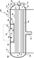
- FIG. 1 is a perspective view of a condenser 100 according to an embodiment of the present application.
- FIG. 2A is a cross-sectional view of the condenser 100 in FIG. 1, taken along a line AA in FIG. 1.
- FIG. 2B is a cross-sectional view of the condenser 100 in FIG. 1 along a line B-B in FIG. 1.
- the condenser 100 includes a housing 112.
- the housing 112 includes a cylinder 102, a left partition plate 116, a right partition plate 114, a left end plate 226, and a right end plate 118.
- the cylinder 102 extends along the length of the condenser 100.
- the left and right ends of the cylinder body 102 are closed by a left partition plate 116 and a right partition plate 114 respectively to form a cavity 202.
- the left end plate 226 is arc-shaped, and the left end plate 226 is connected to the left partition plate 116 to form a communication cavity 208.
- the right end plate 118 is also arc-shaped, and the right end plate 118 is connected to the right partition plate 114.
- the right partition plate 114 further includes a lateral partition plate 210 that extends laterally from the right partition plate 114 to the right end plate 118, thereby forming an outlet cavity 234 and an inlet cavity 232.
- the housing 112 also includes a medium inlet pipe 122 and a medium outlet pipe 124.
- the medium inlet pipe 122 and the medium outlet pipe 124 are disposed on the right end plate 118, and the medium inlet pipe 122 is in fluid communication with the inlet cavity 232.
- the medium outlet pipe 124 and the outlet The cavity 234 is in
- the condenser 100 further includes a first tube bundle 242 and a second tube bundle 244 located below the first tube bundle 242.
- the first tube bundle 242 and the second tube bundle 244 are horizontally disposed in the cavity 202 and extend along the length direction of the condenser 100.
- the cavity 232 is in fluid communication, so that the cooling medium can flow through the inlet cavity 232, the second tube bundle 244, the communication cavity 208, the first tube bundle 242, and the outlet cavity 234 in sequence after passing through the medium inlet pipe 122, and through the medium outlet pipe 124.
- the condenser 100 flows out (in the flow direction shown by the arrow M in FIG. 2A).
- the condenser 100 further includes an inlet pipe 120 and an outlet pipe 130.
- the inlet pipe 120 is located at the upper part of the cylinder 102 and is used for receiving refrigerant gas.
- the outlet pipe 130 is located at the lower part of the barrel 102 and is used to discharge the condensed refrigerant liquid out of the barrel 102.
- the refrigerant gas flowing from the inlet pipe 120 into the barrel 102 performs heat exchange with the medium in the first tube bundle 242 and the second tube bundle 244.
- the refrigerant gas is condensed into a refrigerant liquid and can be discharged out of the barrel 102 through the outlet tube 130.
- the condenser 100 further includes a scour plate 204.
- the impact plate 204 is substantially flat and is transversely disposed in the cavity 202.
- the anti-collision plate 204 is arranged below the inlet pipe 120 and is located above the first tube bundle 242, so that when the refrigerant gas flows from the inlet pipe 120 into the cylinder 102 at a high speed, the anti-collision plate 204 can prevent refrigeration
- the agent gas directly impacts the first tube bundle 242 to prevent the first tube bundle 242 from being broken.
- the anti-collision plate 204 is also arranged to have a distance H from the outlet 224 of the inlet pipe 120, so that the refrigerant fluid can flow out of the outlet 224 to the first tube bundle 242 and the second tube bundle 244.
- the anti-collision plate 204 is welded to the cylinder 102 through a pair of connecting rods 206.
- FIG. 3 is an enlarged view of a dotted frame portion in FIG. 2A to show an embodiment of the structures of the inlet pipe 120 and the anti-collision plate 204 in more detail.
- the inlet pipe 120 is a circular pipe whose inner diameter gradually increases from the inlet 222 to the outlet 224 and has a central axis K.
- the inlet pipe 120 passes through the upper portion of the housing 112, and an outlet 224 of the inlet pipe 120 is received in the cavity 202.
- the inlet 222 of the inlet pipe 120 has an internal diameter D 1
- the outlet 224 of the inlet pipe 120 has an internal diameter D 2.
- the internal diameter of the inlet pipe 120 smoothly increases from the internal diameter D 1 of the inlet 222 to the internal diameter D 2 of the outlet 224.
- the outlet 224 of the inlet pipe 120 has a projection area S on the anti-scoping plate 204 that projects vertically downward along the central axis K of the inlet pipe 120.
- the projection area S is a non-porous area, so that the refrigerant gas can flow along at least a part of the edge of the impact prevention plate 204 along the upper surface of the impact prevention plate 204 and contact the first tube bundle 242, thereby preventing the refrigerant gas from directly impacting the first A tube bundle 242.
- FIG. 4 is a schematic diagram of a part of an axial section of the inlet pipe 120 in FIG. 3 to show a specific shape of an inner wall of the inlet pipe 120.
- x represents the distance of the inner wall of the inlet pipe 120 in the axial section and in a direction perpendicular to the central axis K
- y represents the distance of the inner wall of the inlet pipe 120 in the axial section and in the direction parallel to the central axis K.
- the curve of the inner wall of the inlet pipe 120 in the axial section satisfies any one or more of the following curves, where f, g, h, l, m, n, o, p, q, u, and v represent constants:
- y lx 2 + mx + n, where the value of l is greater than 0, the value of m is greater than -10 and less than 10, and the value of h is greater than -20 and less than 20;
- y ox 3 + px 2 + qx + s, where the range of o is greater than 0, the range of p is greater than -10 and less than 10, the range of q is greater than -20 and less than 20, and h The value range is greater than 0 and less than 100;
- the range of u is that the absolute value of u is greater than 4 and less than 8, and the range of v is that the absolute value of v is greater than 1 and less than 2.
- the inner diameter of the inlet pipe 120 smoothly expands from the inner diameter D 1 of the inlet 222 to the inner diameter D 2 of the outlet 224, which can reduce the friction loss of the refrigerant gas flowing into the inlet pipe 120, and this gradually expanding structure can also make refrigeration The local resistance of the agent gas is reduced.
- the inlet pipe 120 is an equal-thickness pipe.
- the inlet pipe may be a non-equal-thickness pipe.
- FIG. 5 is a schematic diagram of the pressure recovery coefficient Cv of the inlet pipe 120 in FIG. 1 as a function of the ratio AreaRatio.
- the inlet 222 of the inlet pipe 120 has an inlet area A 1
- the edge of the outlet 224 of the inlet pipe 120 extends vertically downward to a surface formed by the impact plate (204) with an outlet extension area A 2.
- the ratio AreaRatio indicates the inlet The ratio of the area A 1 to the exit extension area A 2 .
- the pressure recovery coefficient Cv represents the ratio of the dynamic pressure of the refrigerant gas entering the condenser 100 to the static pressure. For example, when the pressure recovery coefficient Cv is 0.3, it means that 30% of the dynamic pressure is converted into the static pressure.
- the structural arrangement of the inlet pipe 120 and the scour plate 204 can partially convert the dynamic pressure of the refrigerant gas entering the condenser 100 into a static pressure and reduce the refrigerant gas from the inlet 222
- the static pressure loss entering the cylinder 102 increases the condensation pressure of the refrigerant gas in the condenser 100 to enhance the heat exchange performance.
- the value range of a is greater than -2000 and less than 0;
- the value range of b is greater than 0 and less than 20;
- c ranges from greater than 0 to less than 200
- the value of the pressure recovery coefficient Cv ranges from more than 0.4 to less than 0.65.
- FIG. 6A-6C are schematic diagrams of the relative positional relationship between the inlet pipe 120 and the impact plate 204 of the embodiment shown in FIG. 2A, where FIG. 6A is used to show the entrance area A 1 of the inlet 222, and FIG. 6B-6C is used to show the outlet Extending area A 2 .
- the hatched area in FIG. 6A shows the entrance area A 1 of the entrance 222
- the entrance area A 1 is determined by the inner diameter D 1 of the entrance 222.
- the entrance area A 1 and the inner diameter D 1 of the entrance 222 satisfy:
- the edge of the outlet 224 extends vertically downward until the surface formed by the impact plate 204 is an imaginary surface, which is a cylindrical surface and has an outlet extension area A 2 .
- the sum of the shaded portion A 21 in FIG. 6B and the shaded portion A 22 in FIG. 6C is the exit extension area A 2 .
- the shaded area A 21 in FIG. 6B represents a part of the exit extension area A 2 that can be seen from the perspective of FIG. 6B (same as the perspective of FIG. 6C), and the shaded portion A 22 in FIG. 6C represents the perspective of FIG. Same viewing angle) Another part of the exit extension area A 2 that cannot be seen.
- the area A 2 and the inner diameter D 2 of the outlet 224 and the distance H between the outlet 224 and the impact plate 204 satisfy:
- the exit extension area A 2 is related to the circumference of the exit 224 and the distance H between the exit 224 and the impact plate 204.
- FIG. 7A is a cross-sectional view of a condenser 100 taken along a line AA in FIG. 1 according to another embodiment of the present application.
- FIG. 7B is a cross-sectional view of the condenser 100 in FIG. 7A along the line B-B in FIG. 1.
- the arrangement of other components is the same as that of Figs. 2A-2B, except for the structure of the anti-shock plate 204, which is not repeated here.
- both sides of the anti-shock plate 204 in the width direction of the condenser 100 are bent upward to form
- the extension portions 702 and 704 extending upward are connected to the casing 112 through the edge of both sides of the condenser 100 in the width direction of the condenser 100.
- FIGS. 8A-8C are schematic diagrams of the relative positional relationship between the inlet pipe 120 and the impact plate 204 of the embodiment shown in FIG. 7A, where FIG. 8A is used to show the entrance area A 1 of the inlet 222, and FIG. 8B-8C is used to show the outlet
- the edge of 224 extends vertically downward to the exit extension area A 2 of the face formed by the impact plate 204.
- the area A 1 of the entrance 222 shown in FIG. 8A and the calculation method thereof are the same as those in FIG. 6A, and are not repeated here.
- FIGS. 8B-8C the sum of the shaded portion A 21 in FIG. 8B and the shaded portions A 22 and A 23 in FIG. 8C is the exit extension area A 2 .
- the shaded portion A 21 in FIG. 8B represents a part of the exit extension area A 2 that can be seen from the perspective of FIG. 8B (same as the perspective of FIG. 8C), and the shaded portion A 22 in FIG. 8C represents the perspective of FIG. 8C (and FIG. 8B).
- the shaded portion A 23 in FIG. 8C represents the exit blocked by the extension 704 of the scour plate 204 at the angle of view of FIG. 8C (the same as that of FIG. 8B) A part of the extension area A 2 .
- the edge of the outlet 224 extends vertically downward until the surface of the impact plate 204 is a cylindrical surface (that is, a ring shape).
- the edge of the outlet 224 extends vertically downward until the surface formed by the impact plate 204 is not a cylindrical surface.
- the surface formed by the edge of the outlet 224 extending vertically downwards hits the extensions 702, 704 of the impact plate 204, so the cylindrical surface formed by the edge of the outlet 224 extending vertically downwards is partially cut off by the extensions 702, 704.
- the surface formed by the edge of the outlet 224 extending vertically downward is not a cylindrical surface between the outlet 224 and the impact plate 204. Therefore, the exit extension area A 2 is not only related to the circumference of the exit 224 and the distance H between the exit 224 and the impact plate 204, but also to the structural shape of the impact plate 204.
- FIG. 9 is a cross-sectional view of a condenser 100 according to still another embodiment of the present application, taken along a line AA in FIG. 1.
- the arrangement of other components is the same as that of FIGS. 2A-2B except for the structure of the anti-shock plate 204, which is not repeated here.
- a plurality of holes 902 are provided on the anti-collision plate 204, and the plurality of holes 902 are located at the outlet 224 of the inlet pipe 120.
- the anti-collision plate 204 has a center along the inlet pipe 120.
- the axis K is vertically projected downward from the projection area S, so that the refrigerant gas can flow through the holes 902 to the first tube bundle 242 more quickly after being blocked by the anti-skid plate 204.
- the impingement plate in the projection area S 204 is still flat, so in the embodiment shown in Figure 9, the inlet area A of the inlet 222 and the outlet 224 of the edge 1
- the calculation method of the exit extension area A 2 extending vertically down to the impact plate 204 is the same as that illustrated in FIG. 7A.
- impact plates in the present application are generally set as flat plates, those skilled in the art can understand that the impact plates can also be designed into other shapes that are more conducive to the flow of the refrigerant airflow.
- the condensers in this application are all described by taking a shell-and-tube condenser as an example, those skilled in the art can understand that according to the spirit of the present invention, the condenser can be not only a shell-and-tube condenser, Other different types of condensers, such as jacketed condensers.
Landscapes
- Engineering & Computer Science (AREA)
- Physics & Mathematics (AREA)
- Mechanical Engineering (AREA)
- General Engineering & Computer Science (AREA)
- Thermal Sciences (AREA)
- Geometry (AREA)
- Heat-Exchange Devices With Radiators And Conduit Assemblies (AREA)
- Air-Conditioning For Vehicles (AREA)
Abstract
一种冷凝器(100),包括壳体(112)、入口管(120)和防冲板(204)。所述壳体(112)具有容腔(202)。所述入口管(120)为从入口到出口内径逐渐增大的圆管。其中所述入口管(120)被设置为穿过所述壳体(112)的上部,并且所述入口管(120)的出口容纳在所述容腔(202)中。所述防冲板(204)容纳在所述容腔(202)中,并且所述防冲板(204)位于所述入口管(120)的出口的下方。所述防冲板(204)与所述出口之间具有能够使从所述出口流出的流体流过的间距。冷凝器(100)能够减小流入入口管(120)的制冷剂气体的摩擦损失和局部阻力,使得进入冷凝器(100)的制冷剂气体的动压部分地转换成静压,并且减少制冷剂气体从入口进入到筒体的静压损失,从而提高制冷剂气体在冷凝器(100)中的冷凝压力,以增强换热性能。
Description
本申请涉及热交换器领域,更确切地说涉及冷凝器。
冷凝器的壳体内容纳有换热管,冷凝器的入口管通常布置在冷凝器的上部,气态流体从冷凝器的入口管进入冷凝器的壳体内。由于气态流体速度较高,气态流体直接冲击换热管容易引起管热管断裂。
发明内容
本申请的示例性实施例可以解决至少一些上述问题。
本申请提供一种冷凝器,冷凝器包括壳体、入口管和防冲板。所述壳体具有容腔。所述入口管为从入口到出口内径逐渐增大的圆管。其中所述入口管被设置为穿过所述壳体的上部,并且所述入口管的出口容纳在所述容腔中。所述防冲板容纳在所述容腔中,所述防冲板位于所述入口管的出口的下方,并且所述防冲板与所述出口之间具有能够使从所述出口流出的流体流过的间距。
根据上述冷凝器,所述入口管的出口在所述防冲板上具有沿所述入口管的轴向的投影区域,所述投影区域为无孔区。
根据上述冷凝器,所述入口管的内径从所述入口到所述出口平滑地增大。
根据上述冷凝器,所述入口管的所述入口具有入口面积A
1,所述入口管的所述出口的边缘竖直向下延伸至所述防冲板形成的面具有出口延伸面积A
2,入口面积A
1与出口延伸面积A
2的比值AreaRatio满足:
其中,a的取值范围为大于‐2000并且小于0;b的取值范围为大于0并且小于20;c的取值范围为大于0并且小于200;并且压力回收系数Cv的取值范围为大于0.4并且小于0.65。
根据上述冷凝器,所述比值AreaRatio=A
2/A
1的取值范围为大于等于1.65并且小于等于3。
根据上述冷凝器,所述出口延伸面积A
2至少部分地根据所述出口的周长与所述间距H确定。
根据上述冷凝器,所述入口管的内壁在轴截面的曲线满足以下曲线中的任意一种或几种:
(x-f)
2+(y-g)
2=h
2,其中f的取值范围为大于‐1并且小于1,g的取值范围为大于0并且小于100,并且h的取值范围为大于0并且小于100;
y=lx
2+mx+n,其中l的取值范围为大于0,m的取值范围为大于‐10并且小于10,并且h的取值范围为大于‐20并且小于20;
y=ox
3+px
2+qx+s,其中o的取值范围为大于0,p的取值范围为大于‐10并且小于10,q的取值范围为大于‐20并且小于20,并且h的取值范围为大于0并且小于100;
根据上述冷凝器,所述防冲板被配置为使得所述流体沿着所述防冲板的上表面流过所述防冲板的边缘的至少一部分。
根据上述冷凝器,所述防冲板在所述冷凝器的宽度方向上的两侧边缘向上弯折。
根据上述冷凝器,所述防冲板通过所述防冲板在所述冷凝器的宽度方向上的两侧边缘连接在所述壳体上。
本申请的冷凝器能够减小流入入口管的制冷剂气体的摩擦损失和局部阻力,使得进入冷凝器的制冷剂气体的动压部分地转换成静压并且减少制冷剂气体从入口进入到筒体的静压损失,从而提高制冷剂气体在冷凝器中的冷凝压力,以增强换热性能。
本申请特征和优点可通过参照附图阅读以下详细说明得到更好地理解,在整个附图中,相同的附图标记表示相同的部件,其中:
图1是本申请的一个实施例的冷凝器的立体图;
图2A是图1中的冷凝器沿图1中A‐A剖面线的剖视图;
图2B是图1中的冷凝器沿图1中B‐B剖面线的剖视图;
图3是图2A的局部放大图;
图4是图3中入口管的轴截面的一部分的示意图;
图5是图1中入口管的压力回收系数Cv随比值AreaRatio的变化示意图;
图6A‐6C是图2A示出的实施例的入口管与防冲板相对位置关系的示意图;
图7A是根据本申请的另一个实施例的冷凝器沿图1中A‐A剖面线的剖视图;
图7B是图7A中的冷凝器沿图1中B‐B剖面线的剖视图;
图8A‐8C是图7A示出的实施例的入口管与防冲板相对位置关系的示意图;
图9是根据本申请的再一个实施例的冷凝器沿图1中A‐A剖面线的剖视图。
下面将参考构成本说明书一部分的附图对本发明的各种具体实施方式进行描述。应该理解的是,虽然在本发明中使用表示方向的术语,诸如“前”、“后”、“上”、“下”、“左”、“右”、等方向或方位性的描述本发明的各种示例结构部分和元件,但是在此使用这些术语只是为了方便说明的目的,基于附图中显示的示例方位而确定的。由于本发明所公开的实施例可以按照不同的方向设置,所以这些表示方向的术语只是作为说明而不应视作为限制。在以下的附图中,同样的零部件使用同样的附图号,相似的零部件使用相似的附图号。
图1是本申请的一个实施例的冷凝器100的立体图。图2A是图1中的冷凝器100沿图1中A‐A剖面线的剖视图。图2B是图1中的冷凝器100沿图1中B‐B剖面线的剖视图。如图1‐2B所示,冷凝器100包括壳体112。壳体112包括筒体102、左分隔板116、右分隔板114、左端板226和右端板118。其中,筒体102沿冷凝器100的长度方向延伸而成。筒体102的左右两端分别由左分隔板116和右分隔板114封闭,以形成容腔202。左端板226为圆弧形,左端板226与左分隔板116相连接,形成连通腔208。右端板118也为圆弧形,右端板118与右分隔板114相连接。右分隔板114还包括从右分隔板114横向延伸至右端板118的横向分隔板210,从而形成出口容腔234和入口容腔232。壳体112还包括介质入口管122和介质 出口管124,介质入口管122和介质出口管124设置在右端板118上,并且介质入口管122与入口容腔232流体连通,介质出口管124与出口容腔234流体连通。
如图1和图2A所示,冷凝器100还包括第一管束242和位于第一管束242下方的第二管束244。第一管束242和第二管束244水平地置在容腔202中,并且沿冷凝器100的长度方向延伸。第一管束242的一端与连通腔208流体连通,第一管束242的另一端与出口容腔234流体连通;第二管束244的一端与连通腔208流体连通,第二管束244的另一端与入口容腔232流体连通,从而使得冷却介质能够通过介质入口管122后依次流过入口容腔232、第二管束244、连通腔208、第一管束242以及出口容腔234,并通过介质出口管124流出冷凝器100(按图2A中的箭头M示出的流向)。冷凝器100还包括入口管120和出口管130。入口管120位于筒体102的上部,用于接收制冷剂气体。出口管130位于筒体102的下部,用于将冷凝后的制冷剂液体排出筒体102。从入口管120流入筒体102的制冷剂气体与第一管束242和第二管束244中的介质进行热交换,制冷剂气体被冷凝成制冷剂液体后能够通过出口管130排出筒体102。
冷凝器100还包括防冲板204。作为一个示例,防冲板204大致为平板并且被横置在容腔202中。防冲板204被布置在入口管120的下方,并且位于第一管束242的上方,从而使得当制冷剂气体以较高的速度从入口管120流入筒体102时,防冲板204能够防止制冷剂气体直接冲击第一管束242,以避免第一管束242断裂。此外,防冲板204还被布置成与入口管120的出口224之间具有间距H,以使得制冷剂流体能够从出口224流出后流向第一管束242和第二管束244。防冲板204通过一对连接杆206焊接在筒体102上。
图3是图2A中虚线框部分的放大图,以更详细地示出入口管120和防冲板204的结构的一个实施例。如图3所示,入口管120为从入口222到出口224内径逐渐增大的圆管,其具有中心轴线K。入口管120穿过壳体112的上部,并且入口管120的出口224容纳在容腔202中。入口管120的入口222具有内径D
1,入口管120的出口224具有内径D
2,入口管120的内径从入口222的内径D
1平滑地增大到出口224的内径D
2。入口管120的出口224在防冲板204上具有沿入口管120的中心轴线K竖直向下投影的投影区域S。投影区域S为无孔区,以使得制冷剂气体能够沿着防冲板204的上表面流过防冲板204的边缘的至少一部分后与第一管束242接触,从而防止制冷剂气体直接冲击第一管束242。
图4是图3中入口管120的轴截面的一部分的示意图,以示出入口管120的内壁的具体形状。其中x表示入口管120的内壁在轴截面上、并且在垂直于中心轴线K方向上的距离,y 表示入口管120的内壁在轴截面上,并且在平行于中心轴线K方向上的距离。入口管120内壁在轴截面的曲线满足以下曲线中的任意一种或几种,其中f、g、h、l、m、n、o、p、q、u和v表示常数:
(x-f)
2+(y-g)
2=h
2,其中f的取值范围为大于‐1并且小于1,g的取值范围为大于0并且小于100,并且h的取值范围为大于0并且小于100;
y=lx
2+mx+n,其中l的取值范围为大于0,m的取值范围为大于‐10并且小于10,并且h的取值范围为大于‐20并且小于20;
y=ox
3+px
2+qx+s,其中o的取值范围为大于0,p的取值范围为大于‐10并且小于10,q的取值范围为大于‐20并且小于20,并且h的取值范围为大于0并且小于100;
入口管120的内径从入口222的内径D
1平滑地渐扩为出口224的内径D
2能够使流入入口管120的制冷剂气体的摩擦损失减小,并且这种渐扩的结构还能够使制冷剂气体的局部阻力减小。
作为一个示例,入口管120为等厚度管。作为另一个示例,入口管也可以为非等厚度管。
图5是图1中入口管120的压力回收系数Cv随比值AreaRatio的变化示意图。其中,入口管120的入口222具有入口面积A
1,入口管120的出口224的边缘竖直向下延伸至所述防冲板(204)形成的面具有出口延伸面积A
2,比值AreaRatio表示入口面积A
1与出口延伸面积A
2的比值。压力回收系数Cv表示进入冷凝器100的制冷剂气体的动压转换为静压的比例。例如,当压力回收系数Cv为0.3时,表示有30%的动压被转换成静压。具体地说,当比值AreaRatio满足以下公式时,入口管120与防冲板204的结构布置能够使得进入冷凝器100的制冷剂气体的动压部分地转换成静压并且减少制冷剂气体从入口222进入到筒体102的静压损失,从而提高制冷剂气体在冷凝器100中的冷凝压力,以增强换热性能。
如图5所示,压力回收系数Cv与比值AreaRatio的关系满足:
其中,a的取值范围为大于‐2000并且小于0;
b的取值范围为大于0并且小于20;
c的取值范围为大于0并且小于200;并且
压力回收系数Cv的取值范围为大于0.4并且小于0.65。
作为一个示例,比值AreaRatio=A
2/A
1的取值范围为大于等于1.65并且小于等于3。
图6A‐6C是图2A示出的实施例的入口管120与防冲板204相对位置关系的示意图,其中图6A用于示出入口222的入口面积A
1,图6B‐6C用于示出出口延伸面积A
2。如图6A所示,图6A中阴影部分所示为入口222的入口面积A
1,入口面积A
1由入口222的内径D
1确定。具体地说,入口面积A
1与入口222的内径D
1满足:
出口224的边缘竖直向下延伸至防冲板204所形成的面为一个假想的面,其为圆柱面,并且具有出口延伸面积A
2。
如图6B‐6C所示,图6B中阴影部分A
21与图6C中阴影部分A
22的和为出口延伸面积A
2。具体地,图6B中阴影部分A
21表示以图6B视角(与图6C视角相同)能够看到的出口延伸面积A
2的一部分,图6C中阴影部分A
22表示以图6C视角(与图6B视角相同)不能够看到的出口延伸面积A
2的另一部分。
更具体地说,面积A
2与出口224的内径D
2以及出口224与防冲板204之间的间距H满足:
A
2=πHD
2
也就是说,出口延伸面积A
2与出口224的周长以及出口224与防冲板204之间的间距H有关。
图7A是根据本申请的另一个实施例的冷凝器100沿图1中A‐A剖面线的剖视图。图7B是图7A中的冷凝器100沿图1中B‐B剖面线的剖视图。在图7A‐7B所示的冷凝器100中,除了防冲板204的结构不同外,其他部件的设置均与图2A‐2B相同,此处不再赘述。具体来说,在图7A‐7B所示的实施例中,防冲板204在冷凝器100的宽度方向(即,垂直于筒体102的长度方向)上的两侧边缘向上弯折,以形成向上延伸的延伸部702,704,并通过防冲板204在冷凝器100的宽度方向上的两侧边缘与壳体112连接。
图8A‐8C是图7A示出的实施例的入口管120与防冲板204相对位置关系的示意图,其中图8A用于示出入口222的入口面积A
1,图8B‐8C用于示出出口224的边缘竖直向下延伸至防冲板204形成的面的出口延伸面积A
2。图8A中所示的入口222的面积A
1及其计算方法与图6A中相同,此处不再赘述。如图8B‐8C所示,图8B中阴影部分A
21与图8C中阴影部分A
22,A
23的和为出口延伸面积A
2。具体地,图8B中阴影部分A
21表示以图8B视角(与图8C视角相同)能够看到的出口延伸面积A
2的一部分,图8C中阴影部分A
22表示以图8C视角(与图8B视角相同)被入口管120遮住的出口延伸面积A
2的一部分,图8C中阴影部分A
23表示以图8C视角(与图8B视角相同)被防冲板204的延伸部704遮住的出口延伸面积A
2的一部分。
需要说明的是,在图6A‐6C所示出的实施例中,出口224的边缘竖直向下延伸至防冲板204的面为圆柱面(即,环形)。然而,在图8A‐8C所示出的实施例中,出口224的边缘竖直向下延伸至防冲板204形成的面不是圆柱面。具体地说,出口224的边缘竖直向下延伸所形成的面碰到防冲板204的延伸部702,704,因而出口224的边缘竖直向下延伸所形成的圆柱面会被延伸部702,704割除一部分,从而使得出口224的边缘竖直向下延伸所形成的面在出口224与防冲板204之间的面不是圆柱面。因此,出口延伸面积A
2不仅与出口224的周长以及出口224与防冲板204之间的间距H有关,还与防冲板204的结构形状有关。
图9是根据本申请的再一个实施例的冷凝器100沿图1中A‐A剖面线的剖视图。在图9所示的冷凝器100中,除了防冲板204的结构不同外,其他部件的设置均与图2A‐2B相同,此处不再赘述。具体来说,在图9所示的实施例中,防冲板204上设有数个孔洞902,数个孔洞902均处于入口管120的出口224在防冲板204上具有沿入口管120的中心轴线K竖直向下投影的投影区域S外,以使得使得制冷剂气体被防冲板204阻挡后能够通过数个孔洞902更快地流向第一管束242。虽然防冲板204上设有数个孔洞902,但由于投影区域S下的防冲板204仍是平板,因此在图9所示的实施例中,入口222的入口面积A
1与出口224的边缘竖直向下延伸至防冲板204之间的出口延伸面积A
2的计算方式与图7A中所阐述的相同。
需要说明的是,虽然本申请中的防冲板都被大致设置为平板,但本领域的技术人员能够理解,防冲板也可以被设计成其他更有利于制冷剂气流流动的形状结构。
此外,虽然本申请中的冷凝器均以壳管式冷凝器为例进行描述,但是本领域的技术人员能够理解,根据本发明的精神,冷凝器不仅可以是壳管式冷凝器,也可以是其他不同形式的冷凝器,如套管式冷凝器。
尽管本文中仅对本申请的一些特征进行了图示和描述,但是对本领域技术人员来说可以进行多种改进和变化。因此应该理解,所附的权利要求旨在覆盖所有落入本申请实质精神范围内的上述改进和变化。
Claims (10)
- 一种冷凝器(100),其特征在于:所述冷凝器(100)包括:壳体(112),所述壳体(112)具有容腔(202);入口管(120),所述入口管(120)为从入口(222)到出口(224)内径逐渐增大的圆管,其中所述入口管(120)被设置为穿过所述壳体(112)的上部,并且所述入口管(120)的出口(224)容纳在所述容腔(202)中;和防冲板(204),所述防冲板(204)容纳在所述容腔(202)中,所述防冲板(204)位于所述入口管(120)的出口(224)的下方,并且所述防冲板(204)与所述出口(224)之间具有能够使从所述出口(224)流出的流体流过的间距(H)。
- 如权利要求1所述的冷凝器(100),其特征在于:所述入口管(120)的出口(224)在所述防冲板(204)上具有沿所述入口管(120)的轴向的投影区域(S),所述投影区域(S)为无孔区。
- 如权利要求1所述的冷凝器(100),其特征在于:所述入口管(120)的内径从所述入口(222)到所述出口(224)平滑地增大。
- 如权利要求3所述的冷凝器(100),其特征在于:所述入口管(120)的所述入口(222)具有入口面积(A 1);所述入口管(120)的所述出口(224)的边缘竖直向下延伸至所述防冲板(204)形成的面具有出口延伸面积(A 2);所述入口面积(A 1)与所述出口延伸面积(A 2)的比值AreaRatio满足:
 其中,a的取值范围为大于‐2000并且小于0;b的取值范围为大于0并且小于20;c的取值范围为大于0并且小于200;并且压力回收系数Cv的取值范围为大于0.4并且小于0.65。
 - 如权利要求4所述的冷凝器(100),其特征在于:所述比值AreaRatio=A 2/A 1的取值范围为大于等于1.65并且小于等于3。
- 如权利要求4所述的冷凝器(100),其特征在于:所述出口延伸面积(A 2)至少部分地根据所述出口(224)的周长与所述间距(H)确定。
- 如权利要求3所述的冷凝器(100),其特征在于:所述入口管(120)的内壁在轴截面的曲线满足以下曲线中的任意一种或几种:(x-f) 2+(y-g) 2=h 2,其中f的取值范围为大于‐1并且小于1,g的取值范围为大于0并且小于100,并且h的取值范围为大于0并且小于100;y=lx 2+mx+n,其中l的取值范围为大于0,m的取值范围为大于‐10并且小于10,并且h的取值范围为大于‐20并且小于20;y=ox 3+px 2+qx+s,其中o的取值范围为大于0,p的取值范围为大于‐10并且小于10,q的取值范围为大于‐20并且小于20,并且h的取值范围为大于0并且小于100;其中u的取值范围为u的绝对值大于4并且小于8,并且v的取值范围为v的绝对值大于1并且小于2。

- 如权利要求1所述的冷凝器(100),其特征在于:所述防冲板(204)被配置为使得所述流体沿着所述防冲板(204)的上表面流过所述防冲板(204)的边缘的至少一部分。
- 如权利要求1所述的冷凝器(100),其特征在于:所述防冲板(204)在所述冷凝器(100)的宽度方向上的两侧边缘向上弯折。
- 如权利要求1所述的冷凝器(100),其特征在于:所述防冲板(204)通过所述防冲板(204)在所述冷凝器(100)的宽度方向上的两侧边缘连接在所述壳体(112)上。
Priority Applications (3)
| Application Number | Priority Date | Filing Date | Title |
|---|---|---|---|
| KR1020217005159A KR20210036940A (ko) | 2018-07-27 | 2019-07-26 | 응축기 |
| US17/263,844 US20210310705A1 (en) | 2018-07-27 | 2019-07-26 | Condenser |
| EP19840963.3A EP3832242A4 (en) | 2018-07-27 | 2019-07-26 | CONDENSER |
Applications Claiming Priority (4)
| Application Number | Priority Date | Filing Date | Title |
|---|---|---|---|
| CN201821214503.9 | 2018-07-27 | ||
| CN201810843447.3A CN109141077A (zh) | 2018-07-27 | 2018-07-27 | 冷凝器 |
| CN201821214503.9U CN208872149U (zh) | 2018-07-27 | 2018-07-27 | 冷凝器 |
| CN201810843447.3 | 2018-07-27 |
Publications (1)
| Publication Number | Publication Date |
|---|---|
| WO2020020349A1 true WO2020020349A1 (zh) | 2020-01-30 |
Family
ID=69180807
Family Applications (1)
| Application Number | Title | Priority Date | Filing Date |
|---|---|---|---|
| PCT/CN2019/097919 WO2020020349A1 (zh) | 2018-07-27 | 2019-07-26 | 冷凝器 |
Country Status (4)
| Country | Link |
|---|---|
| US (1) | US20210310705A1 (zh) |
| EP (1) | EP3832242A4 (zh) |
| KR (1) | KR20210036940A (zh) |
| WO (1) | WO2020020349A1 (zh) |
Cited By (1)
| Publication number | Priority date | Publication date | Assignee | Title |
|---|---|---|---|---|
| CN111928716A (zh) * | 2020-08-13 | 2020-11-13 | 中国核动力研究设计院 | 一种用于反应堆热交换器的导流装置 |
Families Citing this family (1)
| Publication number | Priority date | Publication date | Assignee | Title |
|---|---|---|---|---|
| CN116941071A (zh) | 2021-03-22 | 2023-10-24 | 株式会社Lg化学 | 正极活性材料、包含其的正极和锂二次电池 |
Citations (7)
| Publication number | Priority date | Publication date | Assignee | Title |
|---|---|---|---|---|
| US20050144976A1 (en) * | 2003-08-27 | 2005-07-07 | Sishtla Vishnu M. | Economizer chamber for minimizing pressure pulsations |
| CN205279537U (zh) * | 2015-12-31 | 2016-06-01 | 江森自控楼宇设备科技(无锡)有限公司 | 带外置过冷器的壳管式冷凝器 |
| CN205279536U (zh) * | 2015-12-31 | 2016-06-01 | 江森自控楼宇设备科技(无锡)有限公司 | 带外置过冷器的壳管式冷凝器 |
| US20160377331A1 (en) * | 2015-06-29 | 2016-12-29 | Johnson Controls Technology Company | Condensation and falling film evaporation hybrid heat exchanger |
| CN206113725U (zh) * | 2016-08-31 | 2017-04-19 | 江苏明浩新能源发展有限公司 | 重质废油处理用冷凝器 |
| CN109141077A (zh) * | 2018-07-27 | 2019-01-04 | 约克(无锡)空调冷冻设备有限公司 | 冷凝器 |
| CN208872149U (zh) * | 2018-07-27 | 2019-05-17 | 约克(无锡)空调冷冻设备有限公司 | 冷凝器 |
Family Cites Families (12)
| Publication number | Priority date | Publication date | Assignee | Title |
|---|---|---|---|---|
| US2607567A (en) * | 1940-07-31 | 1952-08-19 | James C Hobbs | Heat exchanger |
| US3180405A (en) * | 1959-03-11 | 1965-04-27 | Itt | Condensers |
| US4252186A (en) * | 1979-09-19 | 1981-02-24 | Borg-Warner Corporation | Condenser with improved heat transfer |
| US5465783A (en) * | 1994-03-04 | 1995-11-14 | Fedco Automotive Components Company, Inc. | Sacrificial erosion bridge for a heat exchanger |
| US6382313B2 (en) * | 2000-02-25 | 2002-05-07 | Nippon Shokubai Co., Ltd. | Heat exchanger for easily polymerizing substance-containing gas provided with gas distributing plate |
| US20070028647A1 (en) * | 2005-08-04 | 2007-02-08 | York International | Condenser inlet diffuser |
| US8365812B2 (en) * | 2007-06-27 | 2013-02-05 | King Fahd University Of Petroleum And Minerals | Shell and tube heat exchanger |
| US8276653B2 (en) * | 2008-03-28 | 2012-10-02 | Saudi Arabian Oil Company | Raised overlapped impingement plate |
| DE102011013340A1 (de) * | 2010-12-30 | 2012-07-05 | Linde Aktiengesellschaft | Verteileinrichtung und Wärmetauschervorrichtung |
| US10371422B2 (en) * | 2017-02-13 | 2019-08-06 | Daikin Applied Americas Inc. | Condenser with tube support structure |
| CN111630329B (zh) * | 2017-10-10 | 2022-12-02 | 江森自控科技公司 | 加热、通风、空调和制冷系统、冷凝器及其设计方法 |
| CN208332761U (zh) * | 2018-01-16 | 2019-01-04 | 开利公司 | 用于冷凝器的导流板、具有其的冷凝器及制冷系统 |
-
2019
- 2019-07-26 KR KR1020217005159A patent/KR20210036940A/ko not_active Application Discontinuation
- 2019-07-26 WO PCT/CN2019/097919 patent/WO2020020349A1/zh unknown
- 2019-07-26 US US17/263,844 patent/US20210310705A1/en active Pending
- 2019-07-26 EP EP19840963.3A patent/EP3832242A4/en active Pending
Patent Citations (7)
| Publication number | Priority date | Publication date | Assignee | Title |
|---|---|---|---|---|
| US20050144976A1 (en) * | 2003-08-27 | 2005-07-07 | Sishtla Vishnu M. | Economizer chamber for minimizing pressure pulsations |
| US20160377331A1 (en) * | 2015-06-29 | 2016-12-29 | Johnson Controls Technology Company | Condensation and falling film evaporation hybrid heat exchanger |
| CN205279537U (zh) * | 2015-12-31 | 2016-06-01 | 江森自控楼宇设备科技(无锡)有限公司 | 带外置过冷器的壳管式冷凝器 |
| CN205279536U (zh) * | 2015-12-31 | 2016-06-01 | 江森自控楼宇设备科技(无锡)有限公司 | 带外置过冷器的壳管式冷凝器 |
| CN206113725U (zh) * | 2016-08-31 | 2017-04-19 | 江苏明浩新能源发展有限公司 | 重质废油处理用冷凝器 |
| CN109141077A (zh) * | 2018-07-27 | 2019-01-04 | 约克(无锡)空调冷冻设备有限公司 | 冷凝器 |
| CN208872149U (zh) * | 2018-07-27 | 2019-05-17 | 约克(无锡)空调冷冻设备有限公司 | 冷凝器 |
Non-Patent Citations (1)
| Title |
|---|
| See also references of EP3832242A4 * |
Cited By (1)
| Publication number | Priority date | Publication date | Assignee | Title |
|---|---|---|---|---|
| CN111928716A (zh) * | 2020-08-13 | 2020-11-13 | 中国核动力研究设计院 | 一种用于反应堆热交换器的导流装置 |
Also Published As
| Publication number | Publication date |
|---|---|
| EP3832242A1 (en) | 2021-06-09 |
| EP3832242A4 (en) | 2022-04-06 |
| US20210310705A1 (en) | 2021-10-07 |
| KR20210036940A (ko) | 2021-04-05 |
Similar Documents
| Publication | Publication Date | Title |
|---|---|---|
| JP3962798B2 (ja) | 達磨型流路を有する熱交換器用チューブ及びこれを用いた熱交換器 | |
| ES2582946T3 (es) | Diseño de intercambiador de calor para un rendimiento y una fabricabilidad mejorados | |
| WO2020020349A1 (zh) | 冷凝器 | |
| US10113813B2 (en) | Tube for heat exchanger | |
| JP5536420B2 (ja) | セパレート型空気調和機 | |
| JP5147894B2 (ja) | 冷媒分配器、及び、蒸発器 | |
| JP2006336935A (ja) | 冷凍空調機の室外ユニット | |
| EP3951301A1 (en) | Heat exchanger and refrigeration cycle device | |
| JP2018162953A (ja) | 熱交換器 | |
| WO2021235463A1 (ja) | 冷媒分配器、熱交換器及び空気調和装置 | |
| US7290597B2 (en) | Heat exchanger | |
| EP1319908A1 (en) | Heat exchanger | |
| EP3885690B1 (en) | Heat exchanger and refrigeration cycle device | |
| KR100723810B1 (ko) | 열교환기 | |
| CN109141077A (zh) | 冷凝器 | |
| US20230280113A1 (en) | Heat exchanger | |
| KR100606332B1 (ko) | 공조기기의 열교환기용 납작튜브 | |
| JPS6314058A (ja) | 凝縮器 | |
| KR100393564B1 (ko) | 공기조화기용 응축기 | |
| JPS58140597A (ja) | 熱交換器用偏平管 | |
| JPS5822855A (ja) | 凝縮器 | |
| CN113970258A (zh) | 换热器 | |
| JP2020153528A (ja) | 熱交換器及び空気調和機 | |
| JP2663745B2 (ja) | ターボ冷凍機の熱交換装置 | |
| CN114341573A (zh) | 热交换器 |
Legal Events
| Date | Code | Title | Description |
|---|---|---|---|
| 121 | Ep: the epo has been informed by wipo that ep was designated in this application |
Ref document number: 19840963 Country of ref document: EP Kind code of ref document: A1 |
|
| NENP | Non-entry into the national phase |
Ref country code: DE |
|
| ENP | Entry into the national phase |
Ref document number: 20217005159 Country of ref document: KR Kind code of ref document: A |
|
| ENP | Entry into the national phase |
Ref document number: 2019840963 Country of ref document: EP Effective date: 20210301 |