WO2020017409A1 - 攪拌装置及び前処理装置 - Google Patents
攪拌装置及び前処理装置 Download PDFInfo
- Publication number
- WO2020017409A1 WO2020017409A1 PCT/JP2019/027325 JP2019027325W WO2020017409A1 WO 2020017409 A1 WO2020017409 A1 WO 2020017409A1 JP 2019027325 W JP2019027325 W JP 2019027325W WO 2020017409 A1 WO2020017409 A1 WO 2020017409A1
- Authority
- WO
- WIPO (PCT)
- Prior art keywords
- test tube
- motor
- stirring
- cells
- liquid
- Prior art date
- Legal status (The legal status is an assumption and is not a legal conclusion. Google has not performed a legal analysis and makes no representation as to the accuracy of the status listed.)
- Ceased
Links
Images

Classifications
-
- C—CHEMISTRY; METALLURGY
- C12—BIOCHEMISTRY; BEER; SPIRITS; WINE; VINEGAR; MICROBIOLOGY; ENZYMOLOGY; MUTATION OR GENETIC ENGINEERING
- C12M—APPARATUS FOR ENZYMOLOGY OR MICROBIOLOGY; APPARATUS FOR CULTURING MICROORGANISMS FOR PRODUCING BIOMASS, FOR GROWING CELLS OR FOR OBTAINING FERMENTATION OR METABOLIC PRODUCTS, i.e. BIOREACTORS OR FERMENTERS
- C12M27/00—Means for mixing, agitating or circulating fluids in the vessel
- C12M27/02—Stirrer or mobile mixing elements
-
- C—CHEMISTRY; METALLURGY
- C12—BIOCHEMISTRY; BEER; SPIRITS; WINE; VINEGAR; MICROBIOLOGY; ENZYMOLOGY; MUTATION OR GENETIC ENGINEERING
- C12M—APPARATUS FOR ENZYMOLOGY OR MICROBIOLOGY; APPARATUS FOR CULTURING MICROORGANISMS FOR PRODUCING BIOMASS, FOR GROWING CELLS OR FOR OBTAINING FERMENTATION OR METABOLIC PRODUCTS, i.e. BIOREACTORS OR FERMENTERS
- C12M45/00—Means for pre-treatment of biological substances
- C12M45/05—Means for pre-treatment of biological substances by centrifugation
-
- C—CHEMISTRY; METALLURGY
- C12—BIOCHEMISTRY; BEER; SPIRITS; WINE; VINEGAR; MICROBIOLOGY; ENZYMOLOGY; MUTATION OR GENETIC ENGINEERING
- C12M—APPARATUS FOR ENZYMOLOGY OR MICROBIOLOGY; APPARATUS FOR CULTURING MICROORGANISMS FOR PRODUCING BIOMASS, FOR GROWING CELLS OR FOR OBTAINING FERMENTATION OR METABOLIC PRODUCTS, i.e. BIOREACTORS OR FERMENTERS
- C12M33/00—Means for introduction, transport, positioning, extraction, harvesting, peeling or sampling of biological material in or from the apparatus
- C12M33/10—Means for introduction, transport, positioning, extraction, harvesting, peeling or sampling of biological material in or from the apparatus by centrifugation ; Cyclones
Definitions
- the present invention relates to a stirring device for stirring a mixed solution obtained by mixing a reagent with cells.
- Microbial and plant cells are cultured in a culture solution in a culture tank, cells are collected from the culture solution, pre-treated, and then supplied to a liquid chromatograph mass spectrometer for metabolome analysis.
- Techniques for performing analysis are known. In this type of technique, a sampling device for sampling a culture solution containing cells and a pretreatment device for performing pretreatment on cells contained in the sampled culture solution are used. The sampling of the culture solution is performed under aseptic conditions (for example, see Patent Document 1 below).
- the pretreatment device for example, centrifugation of the culture solution, removal of liquid other than the centrifuged cells, supply of reagents to the cells, stirring of a mixed solution containing cells and reagents are sequentially performed.
- the stirring of the liquid mixture is performed by, for example, a dedicated stirring device.
- a stirring device a device that stirs a test tube at a high speed while holding the test tube containing the mixed solution is used.
- Such an apparatus includes a motor and a holding mechanism that holds the test tube at a position distant from the drive shaft of the motor (a position eccentric from the drive shaft). Then, the test tube is moved at a high speed by applying the driving force from the motor to the holding mechanism.
- the motor is continuously rotated at a high speed until the stirring of the mixed liquid is completed. For this reason, a load may be applied to the holding mechanism and the stirring mechanism for a long period of time, and a problem may occur that these mechanisms are damaged. If the time required for stirring is long, a problem occurs in that a portion in contact with the test tube is damaged by abrasion.
- the present invention has been made in view of the above circumstances, and an object of the present invention is to provide a stirring device that can reduce the time required for stirring.
- a stirrer according to the present invention is a stirrer for stirring a mixed solution obtained by mixing a reagent with cells.
- the stirrer includes a pedestal, a motor, and a controller.
- the pedestal receives the bottom of the container containing the mixture.
- the motor has a rotating shaft provided at a position eccentric to the pedestal portion, and rotates the pedestal portion by rotating the rotating shaft.
- the control unit controls rotation of the motor.
- the control unit controls the motor to alternately repeat forward rotation and reverse rotation.
- the motor alternately repeats the forward rotation and the reverse rotation under the control of the control unit.
- the pedestal portion alternately repeats turning in one direction and turning in the other direction.
- the container received by the pedestal portion alternately repeats movement in one direction and movement in the other direction.
- the pretreatment device is a pretreatment device for pretreating cells.
- the pretreatment device includes a centrifugal separation mechanism, a liquid removal mechanism, a reagent supply mechanism, and the stirring device.
- the centrifugation mechanism performs centrifugation on a container containing a culture solution containing cells.
- the liquid removing mechanism removes liquid other than cells centrifuged in the container by the centrifugal separation mechanism.
- the reagent supply mechanism mixes a reagent with cells in the container after the liquid has been removed by the liquid removal mechanism to generate a mixed solution.
- the stirring device stirs the mixture generated by the reagent supply mechanism.
- the time required for stirring in the pretreatment device can be reduced. And the whole working time can be shortened.
- the motor alternately repeats forward rotation and reverse rotation under the control of the control unit.
- the pedestal portion alternately repeats turning in one direction and turning in the other direction.
- the container received by the pedestal portion alternately repeats movement in one direction and movement in the other direction.
- swirls turning in one direction and swirls turning in the other direction are alternately generated in the mixed liquid in the container. Therefore, the mixed liquid in the container can be efficiently stirred. As a result, the time required for stirring the mixed liquid in the container can be reduced.
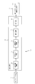
- FIG. 1 is a block diagram illustrating a schematic configuration of an automatic preprocessing system including a preprocessing device according to an embodiment of the present invention.
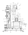
- FIG. 1 is a perspective view illustrating a configuration of a stirring device according to an embodiment of the present invention.
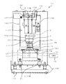
- FIG. 3 is a front view of the stirring device of FIG. 2.
- FIG. 4 is a sectional view taken along line AA of FIG. 3.
- FIG. 1 is a block diagram showing a schematic configuration of an automatic preprocessing system 10 including a preprocessing device according to an embodiment of the present invention.
- the automatic pre-processing system 10 is a device for automatically performing pre-processing on an analysis target.
- the analyte is, for example, a cultured cell, and more specifically, a cell.
- the automatic pre-processing system 10 includes a sampling device 1 and a pre-processing device 2. From the cells that have been pretreated by the automatic pretreatment system 10, metabolites of the cells are extracted and supplied to the liquid chromatograph mass spectrometer 3.
- the liquid chromatograph / mass spectrometer 3 is merely an example of an analyzer for analyzing an analyte, and the analysis can be performed using another analyzer.
- the sampling device 1 is a device for sampling a liquid from a container (culture container). For example, cells of microorganisms and plants are cultured in a culture solution in a container called a bioreactor, and a culture solution containing cells in the bioreactor is sampled by the sampling device 1.
- the bioreactor is provided with, for example, a stirring member that is rotated using magnetic force, an oxygen concentration sensor for detecting the concentration of dissolved oxygen, and the like. Is adjusted, the cells are cultured in the sampling device 1.
- the pretreatment device 2 performs pretreatment on cells contained in the culture solution sampled from inside the bioreactor.
- a culture solution containing cells is accommodated in a test tube as a container (sampling container).
- the pretreatment device 2 is provided with a centrifugal separation mechanism 4, a liquid removal mechanism 5, a reagent supply mechanism 6, a stirring mechanism 7, an extraction mechanism 8, and the like. These mechanisms are included in the culture solution in the test tube. Pretreatment is sequentially performed on the cells.
- the centrifugal separation mechanism 4 performs centrifugation on a test tube containing a culture solution containing cells. Thereby, centrifugal force is applied to the culture solution in the test tube, and the culture solution is separated into cells (solid) and liquid other than cells. Then, the liquid other than the cells centrifuged in the test tube by the centrifugal separation mechanism 4 is removed by using the liquid removal mechanism 5 to collect the cells.
- the reagent is supplied by the reagent supply mechanism 6 into the test tube after the liquid is removed by the liquid removal mechanism 5.
- the reagent is mixed with the cells in the test tube, and a mixed solution is generated.
- the mixed liquid generated by the reagent supply mechanism 6 is stirred by the stirring mechanism 7.
- the reagent used in the present embodiment is a reagent for extracting metabolites in cells, and a suspension in which metabolites are extracted from cells by stirring a mixture of the cells and the reagent. A liquid is obtained. A part of the suspension thus obtained is extracted as an extract by the extraction mechanism 8 and supplied to the liquid chromatograph mass spectrometer 3.
- FIG. 2 is a perspective view showing the configuration of the stirring device 11 according to one embodiment of the present invention.
- FIG. 3 is a front view of the stirring device 11.
- FIG. 4 is a sectional view taken along line AA of FIG.
- the stirring device 11 is provided in the pretreatment device 2 described above.
- the stirring device 11 includes a frame 12, the above-described stirring mechanism 7, a holding mechanism 13, a moving mechanism 14, and a control unit 15.
- the frame 12 is formed in an L shape in a side view, and is made of a metal material.
- the frame 12 includes a horizontal frame 121 and a vertical frame 122.
- the horizontal frame 121 is formed in a plate shape and extends along a horizontal plane.
- the horizontal frame 121 is fixed to an installation surface (not shown).
- the vertical frame 122 is fixed to the upper surface of the horizontal frame 121.
- the vertical frame 122 is formed in a plate shape, and extends upward from one end (the left end in FIGS. 2 and 4) of the horizontal frame 121.
- the stirring mechanism 7 is fixed on the horizontal frame 121.
- the stirring mechanism 7 includes a plurality (four) of legs 71, a housing 72, a base 73, a motor 74, a rotating part 75, a bearing 76, a pedestal 77, and a spring 78. ing.
- Each leg 71 is fixed to the upper surface of the horizontal frame 121.
- Each leg 71 is formed in a tapered shape tapering upward.
- the plurality (four) of the legs 71 are arranged at an interval from each other.
- the housing 72 is fixed on the leg 71.
- the housing 72 is formed in a hollow rectangular parallelepiped shape.
- the base 73 is fixed to the center of the upper surface of the housing 72.
- the base 73 is formed in a cylindrical shape.
- the motor 74 is fixed to the housing 72.
- the motor 74 includes a motor main body 741 and a rotating shaft 742.
- the motor main body 741 is fixed inside the housing 72.
- the rotation shaft 742 extends upward from the motor main body 741.
- the rotation shaft 742 passes through an opening (not shown) formed on the upper surface of the housing 72 and an internal space of the base 73.
- the tip of the rotating shaft 742 is arranged above the housing 72.
- the rotating unit 75 is fixed to the rotating shaft 742.
- the rotating part 75 is formed in a substantially columnar shape.
- the rotating part 75 is formed such that the diameter of the upper part is small and the diameter of the lower part is large.
- a concave portion that is depressed upward is formed in a lower portion of the rotating portion 75.
- the rotating shaft 742 of the motor 74 is inserted into the recess of the rotating part 75.
- the bearing 76 is mounted on the upper end of the rotating part 75. That is, the upper end of the rotating portion 75 passes through the internal space of the bearing 76. A part of the inner surface of the bearing 76 is in contact with the peripheral surface of the upper end of the rotating part 75.
- the pedestal 77 is fixed on the bearing 76.
- the pedestal portion 77 includes a tubular portion 771 and a plate portion 772.
- the cylindrical portion 771 is formed in a cylindrical shape, and is fixed to the bearing 76.
- the cylindrical portion 771 covers the upper surface and the outer peripheral surface of the bearing 76.
- the plate portion 772 is fixed to an upper end portion of the cylindrical portion 771.
- the plate portion 772 is formed in a disk shape and is made of a rubber material. A central portion of the lower surface of the plate portion 772 projects downward. The lower end of the plate portion 772 (the protruding portion at the center of the lower surface) is fitted inside the upper end of the cylindrical portion 771.
- the spring 78 is a coil spring, and is disposed between the base 73 and the pedestal 77 (cylinder 771). Specifically, the lower end of the spring 78 is fixed to the outer peripheral surface of the base 73, and the upper end of the spring 78 is fixed to the outer peripheral surface of the lower end of the cylindrical portion 771.
- the rotating shaft 742 of the motor 74 and the rotating part 75 are arranged inside the spring 78.
- the holding mechanism 13 is a mechanism for holding the test tube S.
- the moving mechanism 14 is a mechanism for moving the holding mechanism 13.
- the moving mechanism 14 is fixed to a vertical frame 122.
- the holding mechanism 13 is connected to the moving mechanism 14.
- the moving mechanism 14 includes an upper / lower cylinder 141, a main body 142, and a connection 143.
- the vertical cylinder 141 is fixed to the lower end of the vertical frame 122.
- the vertical cylinder 141 moves the cylinder in the vertical direction when air is supplied from an air supply unit (not shown).
- the main body 142 is disposed above the vertical cylinder 141.
- the main body 142 constitutes a base of the moving mechanism 14.
- the lower end of the main body 142 is connected to the upper and lower cylinder 141 (the cylinder portion of the upper and lower cylinder 141).
- the main body 142 moves up and down together with the cylinder portion of the vertical cylinder 141.
- the connecting portion 143 is attached to the upper end of the main body 142.
- the connection portion 143 is formed in a columnar shape extending in the horizontal direction. One end (the right end in FIG. 4) of the connecting portion 143 protrudes inward (toward the stirring mechanism 7) from the vertical frame 122.
- the holding mechanism 13 includes an arm 131, a main body 132, and a pair of grips 133. As shown in FIG. 2, the arm 131 is fixed to one end of the connection 143 of the moving mechanism 14.
- the arm portion 131 is formed in a bent plate shape, and extends inward (toward the stirring mechanism 7) from the connection portion 143.
- the main body 132 is formed in a substantially rectangular parallelepiped shape, and is fixed to the arm 131.
- Each grip 133 is attached to the upper end of the main body 132.
- Each grip 133 is formed in a plate shape.
- the pair of holding portions 133 face each other in the horizontal direction.
- the pair of grips 133 are movable in the facing direction along the upper surface of the main body 132.
- the grip 133 moves when air is supplied from an air supply unit (not shown). Specifically, the test tube S is sandwiched between the pair of grip portions 133 by moving so as to approach each other in the facing direction. Further, from this state, the pair of gripping parts 133 moves so as to be separated from each other in the facing direction, so that the holding state of the test tube S is released.
- the control unit 15 is electrically connected to the motor 74 and the like.
- the control unit 15 includes, for example, a CPU (Central Processing Unit), and can control operations of the motor 74 and the like by the CPU executing a control program.
- a CPU Central Processing Unit
- the bearing 76 and the pedestal 77 are provided at positions eccentric with respect to the rotation shaft 742 of the motor 74. Specifically, as shown in FIG. 3, the axis L2 of the pedestal portion 77 (the bearing 76 and the pedestal portion 77) is displaced from the axis L1 of the (rotating shaft 742) of the motor 74 (at a position where they do not match). is there).
- test tube S is held by the holding mechanism 13 in a state where a cap is put on the upper end thereof and along the vertical direction. At this time, the upper end of the test tube S is held by the grip 133 of the holding mechanism 13.
- the test tube S is located above the pedestal portion 77 of the stirring mechanism 7 as shown in FIGS. Are separated.
- the bottom of the test tube S comes into contact with the upper surface of the pedestal portion 77 (plate portion 772).
- the operation of the vertical cylinder 141 is stopped, the movement of the main body 142 and the connection portion 143 is stopped, and the movement of the holding mechanism 13 is stopped. Thereby, the state where the bottom of the test tube S is in contact with the upper surface of the plate portion 772 is maintained.
- the control unit 15 controls the operation of the motor 74 so that the motor 74 alternates between forward rotation and reverse rotation. Specifically, the control unit 15 repeats the operation of performing the forward rotation of the motor 74 for several seconds and then performing the reverse rotation of the motor 74 for several seconds.
- the execution time of each of the forward rotation and the reverse rotation of the motor 74 is, for example, 1 to 3 seconds.
- test tube S (the bottom portion of the test tube S) moves in one direction and in the other direction. Is repeated alternately. As a result, a vortex rotating in one direction and a vortex rotating in the other direction are alternately generated in the liquid mixture in the test tube S.
- the vortex rotating in one direction and the vortex rotating in the other direction alternately occur in the mixed solution in the test tube S
- the vortex already rotating and the newly generated vortex collide when the rotation of the vortex is switched.
- the mixed solution largely moves in the up-down direction.
- the liquid mixture in the test tube S is agitated so as to rotate, and is also agitated so as to move vertically.
- the mixture in the test tube S can be efficiently stirred. Then, the time required for stirring the mixed solution in the test tube S can be reduced.
- the stirring process in the stirring device 11 is completed, the suspension in the test tube S is extracted by the extraction mechanism 8 and supplied to the liquid chromatograph mass spectrometer 3 (see FIG. 1).
- test tube S (the bottom of the test tube S) alternately repeats the movement in one direction and the movement in the other direction. A swirling vortex alternates. Then, the liquid mixture in the test tube S is stirred so as to rotate, and is also stirred so as to move vertically. Therefore, the mixture in the test tube S can be efficiently stirred. As a result, the time required for stirring the liquid mixture in the test tube S can be reduced.
- the stirring mechanism 7 (stirring device 11) is provided in the pretreatment device 2. Therefore, the time required for stirring in the pretreatment device 2 can be reduced. And the whole work time can be shortened.
Landscapes
- Health & Medical Sciences (AREA)
- Life Sciences & Earth Sciences (AREA)
- Organic Chemistry (AREA)
- Engineering & Computer Science (AREA)
- Bioinformatics & Cheminformatics (AREA)
- Chemical & Material Sciences (AREA)
- Zoology (AREA)
- Wood Science & Technology (AREA)
- Sustainable Development (AREA)
- Microbiology (AREA)
- Biotechnology (AREA)
- Biomedical Technology (AREA)
- Biochemistry (AREA)
- General Engineering & Computer Science (AREA)
- General Health & Medical Sciences (AREA)
- Genetics & Genomics (AREA)
- Molecular Biology (AREA)
- Apparatus Associated With Microorganisms And Enzymes (AREA)
- Sampling And Sample Adjustment (AREA)
Abstract
攪拌装置11は、攪拌機構7及び制御部15を備えている。攪拌機構7には、モータ74及び台座部77が含まれる。攪拌装置11では、制御部15の制御によりモータ74が、正回転及び逆回転を交互に繰り返す。そして、台座部77が、一方向への旋回と他方向への旋回とを交互に繰り返す。これにより、試験管Sが、一方向への移動と他方向への移動とを交互に繰り返し、試験管S内の混合液に、一方向に回る渦と他方向に回る渦とが交互に生じる。そして、試験管S内の混合液は、回転するように攪拌されるとともに、上下方向に動くように攪拌される。そのため、試験管S内の混合液を効率良く攪拌することができる。その結果、試験管S内の混合液の攪拌に要する時間を短縮できる。
Description
本発明は、細胞に試薬を混合した混合液を攪拌するための攪拌装置に関するものである。
微生物や植物の細胞を培養槽内の培養液中で培養し、その培養液から細胞を回収して前処理を行った上で、液体クロマトグラフ質量分析装置に供給することにより、メタボローム解析などの分析を行う技術が知られている。この種の技術では、細胞を含む培養液をサンプリングするためのサンプリング装置と、サンプリングされた培養液に含まれる細胞に対して前処理を行うための前処理装置とが用いられている。培養液のサンプリングは、無菌状態にて行われる(例えば、下記特許文献1参照)。
前処理装置では、例えば、培養液に対する遠心分離、遠心分離された細胞以外の液体の除去、細胞への試薬の供給、細胞及び試薬を含む混合液の撹拌などが順次行われる。このうち、混合液の撹拌は、例えば、専用の撹拌装置で行われる。
撹拌装置として、混合液を収容する試験管を保持した状態で、試験管を高速で動かして撹拌を行う装置が利用されている。このような装置は、モータと、モータの駆動軸から離れた位置(駆動軸から偏心した位置)で試験管を保持する保持機構とを備えている。そして、モータからの駆動力が保持機構に付与されることで、試験管が高速で動かされる。
上記した撹拌装置では、混合液の撹拌が完了するまでモータを高速で回転させ続ける。そのため、保持機構や撹拌機構に長時間にわたって負荷がかかり、これらの機構が損傷するという不具合が生じることがあった。撹拌に要する時間が長くなると、特に、試験管と接触する部分が摩耗により損傷するという不具合が生じてしまう。
本発明は、上記実情に鑑みてなされたものであり、撹拌に要する時間を短縮できる撹拌装置を提供することを目的とする。
本発明は、上記実情に鑑みてなされたものであり、撹拌に要する時間を短縮できる撹拌装置を提供することを目的とする。
(1)本発明に係る攪拌装置は、細胞に試薬を混合した混合液を攪拌するための攪拌装置である。前記攪拌装置は、台座部と、モータと、制御部とを備える。前記台座部は、前記混合液が収容された容器の底部を受ける。前記モータは、前記台座部に対して偏心した位置に設けられた回転軸を有し、当該回転軸を回転させることにより前記台座部を旋回させる。前記制御部は、前記モータの回転を制御する。前記制御部は、前記モータが正回転及び逆回転を交互に繰り返すように制御する。
このような構成によれば、攪拌装置では、制御部の制御により、モータが、正回転及び逆回転を交互に繰り返す。そして、台座部が、一方向の旋回と他方向の旋回とを交互に繰り返す。さらに、台座部が受ける容器が、一方向への動きと他方向への動きを交互に繰り返す。
これにより、容器内の混合液に、一方向に回る渦と他方向に回る渦とが交互に生じる。
そのため、容器内の混合液を効率良く攪拌することができる。
その結果、容器内の混合液の攪拌に要する時間を短縮できる。
これにより、容器内の混合液に、一方向に回る渦と他方向に回る渦とが交互に生じる。
そのため、容器内の混合液を効率良く攪拌することができる。
その結果、容器内の混合液の攪拌に要する時間を短縮できる。
(2)本発明に係る前処理装置は、細胞に対する前処理を行うための前処理装置である。前記前処理装置は、遠心分離機構と、液体除去機構と、試薬供給機構と、前記攪拌装置とを備える。前記遠心分離機構は、細胞を含む培養液が収容された容器に対して遠心分離を行う。前記液体除去機構は、前記遠心分離機構により前記容器内で遠心分離された細胞以外の液体を除去する。前記試薬供給機構は、前記液体除去機構により液体が除去された後の前記容器内の細胞に試薬を混合して混合液を生成する。前記攪拌装置は、前記試薬供給機構により生成された混合液を攪拌する。
このような構成によれば、前処理装置において、攪拌に要する時間を短縮できる。そして、全体の作業時間を短縮できる。
本発明によれば、攪拌装置では、制御部の制御により、モータが、正回転及び逆回転を交互に繰り返す。そして、台座部が、一方向の旋回と他方向の旋回とを交互に繰り返す。さらに、台座部が受ける容器が、一方向への動きと他方向への動きを交互に繰り返す。これにより、容器内の混合液に、一方向に回る渦と他方向に回る渦とが交互に生じる。そのため、容器内の混合液を効率良く攪拌することができる。その結果、容器内の混合液の攪拌に要する時間を短縮できる。
1.自動前処理システムの概略構成
図1は、本発明の一実施形態に係る前処理装置を備えた自動前処理システム10の概略構成を示したブロック図である。この自動前処理システム10は、分析対象物に対する前処理を自動で行うための装置である。本実施形態において、分析対象物は、例えば培養された細胞であり、より具体的には菌体である。
図1は、本発明の一実施形態に係る前処理装置を備えた自動前処理システム10の概略構成を示したブロック図である。この自動前処理システム10は、分析対象物に対する前処理を自動で行うための装置である。本実施形態において、分析対象物は、例えば培養された細胞であり、より具体的には菌体である。
自動前処理システム10には、サンプリング装置1及び前処理装置2が備えられている。自動前処理システム10により前処理が行われた後の細胞からは、その細胞の代謝産物が抽出されて、液体クロマトグラフ質量分析装置3に供給される。液体クロマトグラフ質量分析装置3は、分析対象物を分析するための分析装置の一例に過ぎず、他の分析装置を用いて分析を行うことも可能である。
サンプリング装置1は、容器(培養容器)から液体をサンプリングするための装置である。例えば、微生物や植物の細胞は、バイオリアクタと呼ばれる容器内において培養液中で培養され、バイオリアクタ内の細胞を含む培養液がサンプリング装置1によりサンプリングされる。バイオリアクタ内には、例えば磁力を用いて回転される攪拌部材や、溶存酸素の濃度を検知するための酸素濃度センサなどが設けられており、バイオリアクタ内において培養液を攪拌しながら溶存酸素濃度を調整することにより、サンプリング装置1内において細胞が培養される。
前処理装置2は、バイオリアクタ内からサンプリングされた培養液に含まれる細胞に対して前処理を行う。サンプリング装置1では、細胞を含む培養液が、容器(サンプリング容器)としての試験管に収容される。前処理装置2には、遠心分離機構4、液体除去機構5、試薬供給機構6、攪拌機構7及び抽出機構8などが備えられており、これらの各機構により、試験管内の培養液に含まれる細胞に対して前処理が順次行われる。
遠心分離機構4は、細胞を含む培養液が収容された試験管に対して遠心分離を行う。これにより、試験管内の培養液に遠心力が付与され、細胞(固体)と細胞以外の液体とに分離される。そして、遠心分離機構4により試験管内で遠心分離された細胞以外の液体が、液体除去機構5を用いて除去されることにより、細胞が回収される。
液体除去機構5により液体が除去された後の試験管内には、試薬供給機構6により試薬が供給される。これにより、試験管内の細胞に試薬が混合され、混合液が生成される。そして、試薬供給機構6により生成された混合液が、攪拌機構7により攪拌される。
本実施形態において使用される試薬は、細胞中の代謝産物を抽出するための試薬であり、細胞に試薬が混合された混合液を攪拌することにより、細胞中から代謝産物が抽出された懸濁液が得られる。このようにして得られた懸濁液の一部が、抽出液として抽出機構8により抽出され、液体クロマトグラフ質量分析装置3に供給される。
2.攪拌装置の構成
図2は、本発明の一実施形態に係る攪拌装置11の構成を示した斜視図である。図3は、攪拌装置11の正面図である。図4は、図3のA-A線に沿う断面図である。
図2は、本発明の一実施形態に係る攪拌装置11の構成を示した斜視図である。図3は、攪拌装置11の正面図である。図4は、図3のA-A線に沿う断面図である。
攪拌装置11は、上記した前処理装置2に設けられる。攪拌装置11は、フレーム12と、上記した攪拌機構7と、保持機構13と、移動機構14と、制御部15とを備えている。
フレーム12は、側面視L字状に形成されており、金属材料からなる。フレーム12は、水平フレーム121と、鉛直フレーム122とを備えている。水平フレーム121は、板状に形成されており、水平面に沿うように延びている。水平フレーム121は、設置面(図示せず)に固定されている。鉛直フレーム122は、水平フレーム121の上面に固定されている。鉛直フレーム122は、板状に形成されており、水平フレーム121の一端部(図2及び図4における左端部)から上方に向かって延びている。
攪拌機構7は、水平フレーム121上に固定されている。攪拌機構7は、複数(4つ)の脚部71と、筐体72と、基台部73と、モータ74と、回転部75と、ベアリング76と、台座部77と、ばね78とを備えている。
各脚部71は、水平フレーム121の上面に固定されている。各脚部71は、上方に向かって先細るテーパー状に形成されている。複数(4つ)の脚部71は、互いに間隔を隔てて配置されている。
筐体72は、脚部71上に固定されている。筐体72は、中空状の直方体形状に形成されている。
筐体72は、脚部71上に固定されている。筐体72は、中空状の直方体形状に形成されている。
図3及び図4に示すように、基台部73は、筐体72の上面の中央部に固定されている。基台部73は、円筒状に形成されている。
モータ74は、筐体72に固定されている。モータ74は、モータ本体741と、回転軸742とを備えている。モータ本体741は、筐体72内に固定されている。回転軸742は、モータ本体741から上方に向かって延びている。回転軸742は、筐体72の上面に形成された開口(図示せず)、及び、基台部73の内部空間を挿通している。回転軸742の先端部は、筐体72の上方に配置されている。
モータ74は、筐体72に固定されている。モータ74は、モータ本体741と、回転軸742とを備えている。モータ本体741は、筐体72内に固定されている。回転軸742は、モータ本体741から上方に向かって延びている。回転軸742は、筐体72の上面に形成された開口(図示せず)、及び、基台部73の内部空間を挿通している。回転軸742の先端部は、筐体72の上方に配置されている。
回転部75は、回転軸742に固定されている。回転部75は、略円柱状に形成されている。回転部75は、上方側部分の径が小さく、下方側部分の径が大きくなるように形成されている。回転部75の下方側部分には、上方に向かって窪む凹部が形成されている。回転部75の凹部に、モータ74の回転軸742が挿入されている。
ベアリング76は、回転部75の上端部に載置されている。すなわち、回転部75の上端部は、ベアリング76の内部空間を挿通している。ベアリング76の内面の一部は、回転部75の上端部の周面に当接している。
台座部77は、ベアリング76上に固定されている。台座部77は、筒部771と、板部772とを備えている。
筒部771は、円筒状に形成されており、ベアリング76に固定されている。筒部771は、ベアリング76の上面及び外周面を覆っている。
筒部771は、円筒状に形成されており、ベアリング76に固定されている。筒部771は、ベアリング76の上面及び外周面を覆っている。
板部772は、筒部771の上端部に固定されている。板部772は、円板状に形成されており、ゴム材料からなる。板部772の下面の中央部は、下方に向かって突出している。板部772の下端部(下面中央部の突出部分)は、筒部771の上端部の内部に嵌められている。
ばね78は、コイルばねであって、基台部73と台座部77(筒部771)との間に配置されている。具体的には、ばね78の下端部は、基台部73の外周面に固定されており、ばね78の上端部は、筒部771の下端部の外周面に固定されている。モータ74の回転軸742、及び、回転部75は、ばね78の内方に配置されている。
保持機構13は、試験管Sを保持するための機構である。移動機構14は、保持機構13を移動させるための機構である。移動機構14は、鉛直フレーム122に固定されている。保持機構13は、移動機構14に接続されている。
図4に示すように、移動機構14は、上下シリンダ141と、本体部142と、接続部143とを備えている。
上下シリンダ141は、鉛直フレーム122の下端部に固定されている。上下シリンダ141は、空気供給部(図示せず)から空気が供給されることにより、シリンダを上下方向に移動させる。
上下シリンダ141は、鉛直フレーム122の下端部に固定されている。上下シリンダ141は、空気供給部(図示せず)から空気が供給されることにより、シリンダを上下方向に移動させる。
本体部142は、上下シリンダ141の上方に配置されている。本体部142は、移動機構14のベース部分を構成している。本体部142の下端部は、上下シリンダ141(上下シリンダ141におけるシリンダ部分)に接続されている。本体部142は、上下シリンダ141のシリンダ部分とともに上下方向に移動する。
接続部143は、本体部142の上端部に取り付けられている。接続部143は、水平方向に延びる円柱状に形成されている。接続部143の一端部(図4における右端部)は、鉛直フレーム122から内方側(攪拌機構7側)に突出している。
保持機構13は、アーム部131と、本体部132と、1対の把持部133とを備えている。
図2に示すように、アーム部131は、移動機構14の接続部143の一端部に固定されている。アーム部131は、屈曲した板状に形成されており、接続部143から内方側(攪拌機構7側)に延びている。
本体部132は、略直方体形状に形成されており、アーム部131に固定されている。
図2に示すように、アーム部131は、移動機構14の接続部143の一端部に固定されている。アーム部131は、屈曲した板状に形成されており、接続部143から内方側(攪拌機構7側)に延びている。
本体部132は、略直方体形状に形成されており、アーム部131に固定されている。
各把持部133は、本体部132の上端部に取り付けられている。各把持部133は、板状に形成されている。1対の把持部133は、水平方向において互いに対向している。1対の把持部133は、本体部132の上面に沿うようにして対向方向に移動可能である。把持部133は、空気供給部(図示せず)から空気が供給されることにより移動する。具体的には、1対の把持部133が対向方向において近づくように移動することで、それらの間で試験管Sが挟持される。また、この状態から、1対の把持部133が対向方向において離間するように移動することで、試験管Sの挟持状態が解除される。
制御部15は、モータ74などと電気的に接続されている。制御部15は、例えばCPU(Central Processing Unit)を含み、当該CPUが制御プログラムを実行することにより、モータ74などの動作を制御することができる。
攪拌装置11では、ベアリング76及び台座部77は、モータ74の回転軸742に対して偏心した位置に設けられている。具体的には、図3に示すように、台座部77(ベアリング76及び台座部77)の軸線L2は、モータ74の(回転軸742)の軸線L1に対してずれている(一致しない位置にある)。
3.攪拌装置の動作
自動前処理システム10では、まず、細胞を含む培養液が試験管Sに導入され、その試験管Sに対して遠心分離の処理が行われる。これにより、試験管S内の培養液が、細胞(固体)と細胞以外の液体とに分離される。さらに、試験管S内の液体が除去された後、試験管S内に試薬が導入される。そして、この状態の試験管Sが、攪拌装置11に設置される。
自動前処理システム10では、まず、細胞を含む培養液が試験管Sに導入され、その試験管Sに対して遠心分離の処理が行われる。これにより、試験管S内の培養液が、細胞(固体)と細胞以外の液体とに分離される。さらに、試験管S内の液体が除去された後、試験管S内に試薬が導入される。そして、この状態の試験管Sが、攪拌装置11に設置される。
具体的には、試験管Sは、その上端部にキャップが被せられ、かつ、上下方向に沿う状態で、保持機構13に保持される。このとき、試験管Sの上端部は、保持機構13の把持部133により挟持されている。試験管Sが攪拌装置11に設置されたときには、図3及び図4に示すように、試験管Sは、攪拌機構7の台座部77の上方に位置しており、台座部77に対して間隔を隔てている。
この状態から、移動機構14の上下シリンダ141の動作により、本体部142及び接続部143が下方に向かって移動する。そして、接続部143とともに保持機構13が下方に向かって移動する。
すると、試験管Sの底部が、台座部77(板部772)の上面に接触する。試験管Sが板部772に接触すると、上下シリンダ141の動作が停止され、本体部142及び接続部143の移動が停止されて、保持機構13の移動が停止される。これにより、試験管Sの底部が板部772の上面に接触した状態が維持される。
この状態で、制御部15の制御により、モータ74の動作が開始される。このとき、制御部15は、正回転と逆回転とを交互に繰り返すように、モータ74の動作を制御する。
制御部15がモータ74(モータ本体741)を正回転させると、図3に示すように、モータ74の回転軸742は、軸線L1を中心として一方向に回転する。すると、台座部77及びベアリング76が、軸線L1を中心とする円の円周上を軸線L2が移動するようにして、一方向に旋回する。このとき、ばね78は、弾性変形する。このようにして、モータ74の正回転に伴って、台座部77が一方向に旋回する。
また、制御部15がモータ74(モータ本体741)を逆回転させると、モータ74の回転軸742は、軸線L1を中心として他方向に回転する。すると、台座部77及びベアリング76が、軸線L1を中心とする円の円周上を軸線L2が移動するようにして、他方向に旋回する。このとき、ばね78は、弾性変形する。このようにして、モータ74の正回転に伴って、台座部77が他方向に旋回する。
制御部15は、モータ74が正回転と逆回転とを交互に繰り返すように、モータ74の動作を制御する。具体的には、制御部15は、モータ74の正回転を数秒間実施し、その後、モータ74の逆回転を数秒間実施するという動作を繰り返す。モータ74の正回転及び逆回転のそれぞれの実施時間は、例えば、1~3秒である。
このようにして台座部77の一方向への旋回と他方向への旋回が交互に繰り返されると、試験管S(試験管Sの底部)が、一方向への移動と他方向への移動とを交互に繰り返す。これにより、試験管S内の混合液に、一方向に回る渦と他方向に回る渦とが交互に生じる。
試験管S内の混合液に、一方向に回る渦と他方向に回る渦とが交互に生じると、渦の回転の切り替わりの際に、既に回っている渦と新しく発生する渦とがぶつかり合う。これにより、混合液が、上下方向に大きく動く。このようにして、試験管S内の混合液は、回転するように攪拌されるとともに、上下方向に動くように攪拌される。
そのため、試験管S内の混合液を効率良く攪拌することができる。そして、試験管S内の混合液の攪拌に要する時間を短縮できる。
攪拌装置11での攪拌処理が終了すると、試験管S内の懸濁液は、抽出機構8により抽出され、液体クロマトグラフ質量分析装置3に供給される(図1参照)。
攪拌装置11での攪拌処理が終了すると、試験管S内の懸濁液は、抽出機構8により抽出され、液体クロマトグラフ質量分析装置3に供給される(図1参照)。
4.作用効果
(1)本実施形態では、攪拌装置11において、制御部15の制御により、モータ74が、正回転及び逆回転を交互に繰り返す。そして、台座部77が、一方向への旋回と他方向への旋回とを交互に繰り返す。
(1)本実施形態では、攪拌装置11において、制御部15の制御により、モータ74が、正回転及び逆回転を交互に繰り返す。そして、台座部77が、一方向への旋回と他方向への旋回とを交互に繰り返す。
これにより、試験管S(試験管Sの底部)が、一方向への移動と他方向への移動とを交互に繰り返し、試験管S内の混合液に、一方向に回る渦と他方向に回る渦とが交互に生じる。そして、試験管S内の混合液は、回転するように攪拌されるとともに、上下方向に動くように攪拌される。
そのため、試験管S内の混合液を効率良く攪拌することができる。
その結果、試験管S内の混合液の攪拌に要する時間を短縮できる。
そのため、試験管S内の混合液を効率良く攪拌することができる。
その結果、試験管S内の混合液の攪拌に要する時間を短縮できる。
(2)また、本実施形態では、攪拌機構7(攪拌装置11)は、前処理装置2に設けられる。
そのため、前処理装置2において、攪拌に要する時間を短縮できる。そして、全体の作業時間を短縮できる。
そのため、前処理装置2において、攪拌に要する時間を短縮できる。そして、全体の作業時間を短縮できる。
5.変形例
以上の実施形態では、培養液から生成される混合液を攪拌装置11で攪拌する場合について説明した。しかし、攪拌装置11は、他の任意の液体を攪拌する場合に用いることができる。
以上の実施形態では、培養液から生成される混合液を攪拌装置11で攪拌する場合について説明した。しかし、攪拌装置11は、他の任意の液体を攪拌する場合に用いることができる。
2 前処理装置
4 遠心分離機構
5 液体除去機構
6 試薬供給機構
7 攪拌機構
11 攪拌装置
15 制御部
74 モータ
77 台座部
741 モータ本体
742 回転軸
771 筒部
772 板部
4 遠心分離機構
5 液体除去機構
6 試薬供給機構
7 攪拌機構
11 攪拌装置
15 制御部
74 モータ
77 台座部
741 モータ本体
742 回転軸
771 筒部
772 板部
Claims (2)
- 細胞に試薬を混合した混合液を攪拌するための攪拌装置であって、
前記混合液が収容された容器の底部を受ける台座部と、
前記台座部に対して偏心した位置に設けられた回転軸を有し、当該回転軸を回転させることにより前記台座部を旋回させるモータと、
前記モータの回転を制御する制御部とを備え、
前記制御部は、前記モータが正回転及び逆回転を交互に繰り返すように制御することを特徴とする攪拌装置。 - 細胞に対する前処理を行うための前処理装置であって、
細胞を含む培養液が収容された容器に対して遠心分離を行う遠心分離機構と、
前記遠心分離機構により前記容器内で遠心分離された細胞以外の液体を除去する液体除去機構と、
前記液体除去機構により液体が除去された後の前記容器内の細胞に試薬を混合して混合液を生成する試薬供給機構と、
前記試薬供給機構により生成された混合液を攪拌する請求項1に記載の攪拌装置とを備えることを特徴とする前処理装置。
Priority Applications (2)
| Application Number | Priority Date | Filing Date | Title |
|---|---|---|---|
| US17/259,612 US20210292698A1 (en) | 2018-07-17 | 2019-07-10 | Stirring device and preprocessing device |
| JP2020531264A JP7421192B2 (ja) | 2018-07-17 | 2019-07-10 | 攪拌装置及び前処理装置 |
Applications Claiming Priority (2)
| Application Number | Priority Date | Filing Date | Title |
|---|---|---|---|
| JP2018134174 | 2018-07-17 | ||
| JP2018-134174 | 2018-07-17 |
Publications (1)
| Publication Number | Publication Date |
|---|---|
| WO2020017409A1 true WO2020017409A1 (ja) | 2020-01-23 |
Family
ID=69163646
Family Applications (1)
| Application Number | Title | Priority Date | Filing Date |
|---|---|---|---|
| PCT/JP2019/027325 Ceased WO2020017409A1 (ja) | 2018-07-17 | 2019-07-10 | 攪拌装置及び前処理装置 |
Country Status (3)
| Country | Link |
|---|---|
| US (1) | US20210292698A1 (ja) |
| JP (1) | JP7421192B2 (ja) |
| WO (1) | WO2020017409A1 (ja) |
Cited By (1)
| Publication number | Priority date | Publication date | Assignee | Title |
|---|---|---|---|---|
| CN115046840A (zh) * | 2022-06-14 | 2022-09-13 | 巨翊医疗科技(苏州)有限公司 | 一种使样本和溶液充分搅拌混合的方法 |
Citations (5)
| Publication number | Priority date | Publication date | Assignee | Title |
|---|---|---|---|---|
| JP2005127861A (ja) * | 2003-10-23 | 2005-05-19 | Aloka Co Ltd | 分注装置 |
| JP2014504731A (ja) * | 2011-01-21 | 2014-02-24 | セラノス, インコーポレイテッド | 試料使用の極大化のためのシステム及び方法 |
| WO2016006097A1 (ja) * | 2014-07-11 | 2016-01-14 | 株式会社島津製作所 | 前処理装置 |
| JP2017198625A (ja) * | 2016-04-28 | 2017-11-02 | シスメックス株式会社 | 前処理装置及び検体分析装置 |
| JP2018096916A (ja) * | 2016-12-15 | 2018-06-21 | シスメックス株式会社 | 前処理装置及び前処理方法 |
Family Cites Families (2)
| Publication number | Priority date | Publication date | Assignee | Title |
|---|---|---|---|---|
| JP3237504B2 (ja) * | 1995-01-25 | 2001-12-10 | 富士レビオ株式会社 | 容器の保持機構及び該保持機構を用いた容器の攪拌装置 |
| JP3918153B2 (ja) * | 2003-02-17 | 2007-05-23 | 日本パルスモーター株式会社 | 分注装置 |
-
2019
- 2019-07-10 JP JP2020531264A patent/JP7421192B2/ja active Active
- 2019-07-10 US US17/259,612 patent/US20210292698A1/en not_active Abandoned
- 2019-07-10 WO PCT/JP2019/027325 patent/WO2020017409A1/ja not_active Ceased
Patent Citations (5)
| Publication number | Priority date | Publication date | Assignee | Title |
|---|---|---|---|---|
| JP2005127861A (ja) * | 2003-10-23 | 2005-05-19 | Aloka Co Ltd | 分注装置 |
| JP2014504731A (ja) * | 2011-01-21 | 2014-02-24 | セラノス, インコーポレイテッド | 試料使用の極大化のためのシステム及び方法 |
| WO2016006097A1 (ja) * | 2014-07-11 | 2016-01-14 | 株式会社島津製作所 | 前処理装置 |
| JP2017198625A (ja) * | 2016-04-28 | 2017-11-02 | シスメックス株式会社 | 前処理装置及び検体分析装置 |
| JP2018096916A (ja) * | 2016-12-15 | 2018-06-21 | シスメックス株式会社 | 前処理装置及び前処理方法 |
Cited By (1)
| Publication number | Priority date | Publication date | Assignee | Title |
|---|---|---|---|---|
| CN115046840A (zh) * | 2022-06-14 | 2022-09-13 | 巨翊医疗科技(苏州)有限公司 | 一种使样本和溶液充分搅拌混合的方法 |
Also Published As
| Publication number | Publication date |
|---|---|
| US20210292698A1 (en) | 2021-09-23 |
| JP7421192B2 (ja) | 2024-01-24 |
| JPWO2020017409A1 (ja) | 2021-08-02 |
Similar Documents
| Publication | Publication Date | Title |
|---|---|---|
| US9791469B2 (en) | Pipetting device | |
| WO2013002268A1 (ja) | 液体処理システム及び液体処理方法 | |
| EP2045606A2 (en) | Automated analyzer | |
| US10926232B2 (en) | Automatic analyzing apparatus | |
| WO2020017409A1 (ja) | 攪拌装置及び前処理装置 | |
| CN119823850A (zh) | 一种龙门架及自动提取设备 | |
| US5723092A (en) | Sample dilution system and dilution well insert therefor | |
| US12258251B2 (en) | Cap attaching/detaching device, and sampling device and pre-processing device provided with same | |
| JP7007658B2 (ja) | 攪拌装置及び前処理装置 | |
| CN101205246B (zh) | 一种核酸提取装置 | |
| CN109929757B (zh) | 一种新型核酸提取仪 | |
| JP7084581B2 (ja) | 固液界面検出装置及びこれを備えた前処理装置 | |
| JPH03296428A (ja) | 撹拌装置 | |
| JP2022506520A (ja) | 非同心状の塊を使用してピペットを振動させることによって流体またはメディアを混ぜる装置と方法 | |
| KR102478198B1 (ko) | 타겟물질의 자동 분리 장치, 이를 구비한 액체 핸들링 시스템 및 분리 방법 | |
| CN102151509B (zh) | 一种用于多物质混匀的自动化装置 | |
| JPH11326338A (ja) | 反応テーブル | |
| CN224163635U (zh) | 一种白酒检测滴定装置 | |
| CN200992526Y (zh) | 一种核酸提取装置 | |
| CN223393324U (zh) | 一种碘化物提取震荡摇匀装置 | |
| CN219871364U (zh) | 蛋白质抗原检测装置 | |
| CN115228626B (zh) | 一种离心机及具有该离心机的全自动试验仪器 | |
| CN120749000B (zh) | 一种用于质谱分析的纸基电喷雾电离源一体化装置及方法 | |
| CN223155038U (zh) | 自动进样装置 | |
| CN215901633U (zh) | 一种容量瓶摇匀装置 |
Legal Events
| Date | Code | Title | Description |
|---|---|---|---|
| 121 | Ep: the epo has been informed by wipo that ep was designated in this application |
Ref document number: 19838832 Country of ref document: EP Kind code of ref document: A1 |
|
| ENP | Entry into the national phase |
Ref document number: 2020531264 Country of ref document: JP Kind code of ref document: A |
|
| NENP | Non-entry into the national phase |
Ref country code: DE |
|
| 122 | Ep: pct application non-entry in european phase |
Ref document number: 19838832 Country of ref document: EP Kind code of ref document: A1 |