WO2020017143A1 - Motor - Google Patents
Motor Download PDFInfo
- Publication number
- WO2020017143A1 WO2020017143A1 PCT/JP2019/019821 JP2019019821W WO2020017143A1 WO 2020017143 A1 WO2020017143 A1 WO 2020017143A1 JP 2019019821 W JP2019019821 W JP 2019019821W WO 2020017143 A1 WO2020017143 A1 WO 2020017143A1
- Authority
- WO
- WIPO (PCT)
- Prior art keywords
- coil
- outer peripheral
- annular body
- stator
- conductor
- Prior art date
Links
Images


Classifications
-
- H—ELECTRICITY
- H01—ELECTRIC ELEMENTS
- H01F—MAGNETS; INDUCTANCES; TRANSFORMERS; SELECTION OF MATERIALS FOR THEIR MAGNETIC PROPERTIES
- H01F5/00—Coils
-
- H—ELECTRICITY
- H02—GENERATION; CONVERSION OR DISTRIBUTION OF ELECTRIC POWER
- H02K—DYNAMO-ELECTRIC MACHINES
- H02K3/00—Details of windings
- H02K3/04—Windings characterised by the conductor shape, form or construction, e.g. with bar conductors
- H02K3/18—Windings for salient poles
-
- H—ELECTRICITY
- H02—GENERATION; CONVERSION OR DISTRIBUTION OF ELECTRIC POWER
- H02K—DYNAMO-ELECTRIC MACHINES
- H02K3/00—Details of windings
- H02K3/04—Windings characterised by the conductor shape, form or construction, e.g. with bar conductors
- H02K3/24—Windings characterised by the conductor shape, form or construction, e.g. with bar conductors with channels or ducts for cooling medium between the conductors
-
- H—ELECTRICITY
- H01—ELECTRIC ELEMENTS
- H01F—MAGNETS; INDUCTANCES; TRANSFORMERS; SELECTION OF MATERIALS FOR THEIR MAGNETIC PROPERTIES
- H01F41/00—Apparatus or processes specially adapted for manufacturing or assembling magnets, inductances or transformers; Apparatus or processes specially adapted for manufacturing materials characterised by their magnetic properties
- H01F41/02—Apparatus or processes specially adapted for manufacturing or assembling magnets, inductances or transformers; Apparatus or processes specially adapted for manufacturing materials characterised by their magnetic properties for manufacturing cores, coils, or magnets
- H01F41/04—Apparatus or processes specially adapted for manufacturing or assembling magnets, inductances or transformers; Apparatus or processes specially adapted for manufacturing materials characterised by their magnetic properties for manufacturing cores, coils, or magnets for manufacturing coils
Definitions
- the present invention relates to a motor.
- the present invention particularly relates to a configuration of a stator coil of a motor.
- ⁇ Heat is one of the factors that lowers the motor efficiency, and it is known that a refrigerant is circulated inside the motor to suppress a rise in temperature (for example, see Patent Document 2).
- the dead space in the slot is reduced.
- the dead space forms a part of the flow path of the refrigerant, and a decrease in the dead space in the slot is equivalent to a decrease in the flow path of the refrigerant, and decreases the flow rate of the refrigerant.
- the cooling effect by the refrigerant does not work effectively.
- the self-temperature rise due to the heat generated by the stator coil or the teeth constituting the magnetic core of the stator coil becomes excessive, which causes a reduction in the efficiency of the motor.
- the motor efficiency is a ratio of the mechanical output from the motor to the input power to the motor, expressed as a percentage (percentage, unit symbol [%]).
- the space factor is a ratio of a conductor portion such as a conductive wire to a housing sectional area of a winding housing portion such as a slot or an insulator. If the cross section of a conductor or the like is circular, a dead space is generated between adjacent circles, and there is a limit to increasing the space factor.
- the thickness of the insulating film of the conductive wire also causes a reduction in the space factor. Incidentally, when the thickness of the insulating coating of the conductor is constant, the smaller the diameter of the conductor, the higher the ratio of the thickness of the insulating coating or the area occupied by the insulating coating.
- the object of the present invention is to provide a motor having a configuration in which the space factor of the stator coil is increased, thereby realizing a highly efficient motor by further increasing the cooling effect of the stator coil by the refrigerant.
- a motor of the present invention includes a stator core and a stator coil having teeth protruding from the stator core as a magnetic core.
- the stator coil is a spiral coil having a spiral laminated structure including a predetermined n-turn (n is a natural number) annular body.
- n is a natural number
- the aspect of the stator coil in the motor of the present invention is also expressed as a single-layer solenoid coil.
- the stator coil which is a helical coil, is formed of an annular body including a conducting wire portion having a polygonal cross section. Of the plurality of turns of the helical coil, at least part of the coil top portion and the coil bottom portion of the helical coil at least partially on the outer peripheral side of the shape of the adjacent other turns of the helical coil. It constitutes a mode of small shape. Note that both the coil top portion and the coil bottom portion may be referred to as a coil end portion.
- the stator coil in the motor of the present invention has a structure that increases a heat radiation area for air, refrigerant, oil, and the like, and also has a circulation passage for air, refrigerant, oil, and the like. It is the structure which increases. Thereby, the cooling effect of the stator coil can be efficiently increased. Therefore, a highly efficient motor can be realized.
- the stator coil which is a spiral coil, has a width of a conductor of the annular body of a part of turns between adjacent spiral coils in a slot of a stator of a motor among a plurality of annular bodies included in the stator coil.
- the aspect in which the size is a width smaller than the width of the conductor of the annular body adjacent to the annular body is included.
- the stator coil in the motor of the present invention has a structure that increases the heat radiation area for air, refrigerant, oil, and the like, as compared with the stator coil illustrated as a conventional example.
- a structure is provided in which circulation paths for air, refrigerant, oil, and the like are increased.
- fluids such as air, refrigerant, and oil pass through a gap (oil passage) near the stator coil from the upstream side of the flow, pass downstream of the flow, and further smoothly circulate, increasing the heat radiation effect. It becomes possible. The details are described below.
- a motor includes, at least, a stator core including a stacked body in which a plurality of stator core sheets are stacked, and a stator including a stator coil including teeth provided in the stator core as a part of a magnetic core.
- the stator coil includes: A spiral coil including an annular body having a predetermined number of turns is formed, the annular body includes a conductor, the conductor has a conductor and an insulating coating covering the conductor, and a cross-sectional shape of the conductor Is substantially square, A part of the annular body positioned on each side of the tooth stacking surface is defined as a coil line part, and a part that is part of the annular body and located between the same-direction ends of the pair of coil line parts is a coil line part.
- An end portion is defined, and a transition from one end of the coil line portion to one end of the coil end portion is defined as a coil corner portion.
- the outer periphery of the coil end portion and the outer periphery of the coil line portion are defined. And at least one recessed portion that is recessed with respect to the virtual envelope surface including the portion and the outer peripheral portion of the coil corner portion.
- a motor including at least a stator core including a stacked body in which a plurality of stator core sheets are stacked, a stator including a stator coil having teeth provided in the stator core as a part of a magnetic core, and a stator core including: A motor including a tip of a tooth and a rotor rotatably supported through a gap, The stator coil constitutes a helical coil including an annular body having a predetermined number of turns, the annular body includes a conductor portion, and the conductor portion has a conductor portion and an insulating coating covering the conductor portion.
- the cross-sectional shape of the part is substantially square, A part of the annular body positioned on each side of the tooth stacking surface is defined as a coil line part, and a part that is part of the annular body and located between the same-direction ends of the pair of coil line parts is a coil line part.
- an outer peripheral portion of a coil end portion, an outer peripheral portion of a coil line portion, and a plurality of concave portions that are depressed with respect to a virtual envelope surface including an outer peripheral portion of a coil corner portion In the spiral coil, an outer peripheral portion of a coil end portion, an outer peripheral portion of a coil line portion, and a plurality of concave portions that are depressed with respect to a virtual envelope surface including an outer peripheral portion of a coil corner portion,
- the plurality of recesses are located on the coil end side of the spiral coil, In at least one of the plurality of recesses, the outer periphery of the coil end portion and the outer periphery of the coil corner portion of the one-turn annular body are located at the bottom of the recess, and, In at least another one of the plurality of concave portions, the outer peripheral portion of the coil end portion and the outer peripheral portion of the coil corner portion of the plurality of turns of the annular body adjacent to each other are located at the bottom of the concave portion
- a motor including at least a stator core including a stacked body in which a plurality of stator core sheets are stacked, a stator including a stator coil having teeth provided on the stator core as a part of a magnetic core, and a stator core.
- a portion located between the coil ends is defined as a coil end portion, and a transition from one end of the coil line portion to one end of the coil end portion is defined as a coil corner portion, in the spiral coil, the coil end portion
- An outer peripheral portion, an outer peripheral portion of the coil line portion, and a plurality of concave portions recessed with respect to a virtual envelope surface including an outer peripheral portion of the coil corner portion, the plurality of concave portions are provided on a side of the spiral coil near the coil line portion.
- the outer peripheral portion of the outer peripheral portion and the coil corners of the coil line of the annular body of one turn is positioned,
- at least another one of the plurality of recesses has an outer peripheral portion of a coil line portion and an outer peripheral portion of a coil corner portion of a plurality of turns of an annular body adjacent to each other located at the bottom of the concave portion.
- a motor including at least a stator core including a stacked body in which a plurality of stator core sheets are stacked, a stator including a stator coil having teeth provided on the stator core as a part of a magnetic core, and a stator core.
- a portion located between the coil ends is defined as a coil end portion, and a transition from one end of the coil line portion to one end of the coil end portion is defined as a coil corner portion, in the spiral coil, the coil end portion
- An outer peripheral portion, an outer peripheral portion of the coil line portion, and a plurality of concave portions recessed with respect to a virtual envelope surface including an outer peripheral portion of the coil corner portion, the plurality of concave portions are provided on a side of the spiral coil near the coil line portion.
- a motor including at least a stator core including a stacked body in which a plurality of stator core sheets are stacked, a stator including a stator coil having teeth provided on the stator core as a part of a magnetic core, and a stator core.
- the stator coil is A spiral coil including an annular body having a predetermined number of turns is formed, the annular body includes a conductor, the conductor has a conductor and an insulating coating covering the conductor, and a cross-sectional shape of the conductor Is substantially square, A part of the annular body positioned on each side of the tooth stacking surface is defined as a coil line part, and a part that is part of the annular body and located between the same-direction ends of the pair of coil line parts is a coil line part.
- the spiral coil includes a plurality of recesses that are recessed with respect to a virtual envelope including an outer peripheral portion of a coil end portion, an outer peripheral portion of a coil line portion, and an outer peripheral portion of a coil corner portion.
- the outer periphery of the coil line portion and the outer periphery of the coil corner portion in one turn of each of the annular bodies are located at the bottom of the recess at each of the plurality of recesses. .
- a motor including at least a stator core including a stacked body in which a plurality of stator core sheets are stacked, a stator including a stator coil having teeth provided on the stator core as a part of a magnetic core, and a stator core.
- a portion located between the coil ends is defined as a coil end portion, and a transition from one end of the coil line portion to one end of the coil end portion is defined as a coil corner portion, in the spiral coil, the coil end portion
- a motor including at least a stator core including a stacked body in which a plurality of stator core sheets are stacked, a stator including a stator coil having teeth provided on the stator core as a part of a magnetic core, and a stator core.
- an outer peripheral portion of a coil end portion, an outer peripheral portion of a coil line portion, and a plurality of concave portions that are depressed with respect to a virtual envelope surface including an outer peripheral portion of a coil corner portion In the spiral coil, an outer peripheral portion of a coil end portion, an outer peripheral portion of a coil line portion, and a plurality of concave portions that are depressed with respect to a virtual envelope surface including an outer peripheral portion of a coil corner portion,
- the plurality of recesses are located over the outer peripheral surface of the spiral coil, In each of the plurality of recesses, an outer peripheral portion of a plurality of turns of the annular body adjacent to each other is located at the bottom of the recess.
- a motor including at least a stator core including a stacked body in which a plurality of stator core sheets are stacked, a stator including a stator coil having teeth provided on the stator core as a part of a magnetic core, and a stator core.
- the stator coil is A spiral coil including an annular body having a predetermined number of turns is formed, the annular body includes a conductor, the conductor has a conductor and an insulating coating covering the conductor, and a cross-sectional shape of the conductor Are substantially rectangular, and define a part of the annular body located on each side of the teeth on the stacking surface side as a coil line part, and are a part of the annular body and the same direction ends of a pair of coil line parts.
- a portion located between the coil ends is defined as a coil end portion, and a transition from one end of the coil line portion to one end of the coil end portion is defined as a coil corner portion, in the spiral coil, the coil end portion
- Each of the plurality of recesses has a recess The bottom, the outer peripheral portion of the annular body of one turn is located.
- a motor including at least a stator core including a stacked body in which a plurality of stator core sheets are stacked, a stator including a stator coil having teeth provided on the stator core as a part of a magnetic core, and a stator core.
- the stator coil is A spiral coil including an annular body having a predetermined number of turns is formed, the annular body includes a conductor, the conductor has a conductor and an insulating coating covering the conductor, and a cross-sectional shape of the conductor Is substantially square, A part of the annular body positioned on each side of the tooth stacking surface is defined as a coil line part, and a part that is part of the annular body and located between the same-direction ends of the pair of coil line parts is a coil line part.
- the outer periphery of the one-turn annular body is located at the bottom of the recess, And, at least another one of the plurality of recesses, at the bottom of the recess, the outer periphery of the annular body of a plurality of turns adjacent to each other is located, Further, at least another one of the plurality of recesses is a groove-shaped recess communicating from the start turn to the end turn of a predetermined number of turns, and a different one of the plurality of recesses. The longitudinal directions of the groove-like shapes of the concave portions intersect each other.
- a motor including at least a stator core including a stacked body in which a plurality of stator core sheets are stacked, a stator including a stator coil having teeth provided on the stator core as a part of a magnetic core, and a stator core.
- a portion located between the coil ends is defined as a coil end portion, and a transition from one end of the coil line portion to one end of the coil end portion is defined as a coil corner portion, in the spiral coil, the coil end portion In the virtual envelope including the outer peripheral portion, the outer peripheral portion of the coil line portion, and the outer peripheral portion of the coil corner portion, the central portion of the coil end portion from the start turn to the end turn of a predetermined number of turns.
- a ridgeline a ridgeline Comprising a slope descending to the coil corners Luo each.
- the motor of still another aspect of the present invention further includes one or more concave portions that are concave with respect to the virtual envelope surface,
- the plurality of recesses are located on the coil end portion side of the spiral coil, and at least one of the plurality of recesses has a one-turn annular body outer end portion of the coil end portion and a coil corner portion on the bottom of the recess.
- the outer part is located, In at least one of the plurality of recesses, the outer periphery of the coil end portion and the outer periphery of the coil corner portion of the plurality of turns of the annular body adjacent to each other are located at the bottom of the recess.
- the motor according to still another aspect of the present invention further includes one or a plurality of recesses that are recessed with respect to the virtual envelope, and the plurality of recesses are located on the coil line side of the spiral coil. Then, in at least one of the plurality of recesses, the outer circumference of the coil line portion and the outer circumference of the coil corner portion of the one-turn annular body are located at the bottom of the recess. In addition, in at least one of the plurality of recesses, the outer periphery of the coil line portion and the outer periphery of the coil corner portion of the plurality of turns of the annular body adjacent to each other are located at the bottom of the recess.
- the plurality of recesses are located over an outer peripheral surface of the spiral coil, and at least one of the plurality of recesses has a one-turn annular shape at the bottom of the recess.
- the outer periphery of the body is located,
- an outer peripheral portion of a plurality of turns of the annular body adjacent to each other is located at the bottom of the recess.
- a motor includes at least a stator core including an embodiment of a stacked body in which a plurality of stator core sheets are stacked, and a stator including a stator coil having teeth provided on the stator core as a part of a magnetic core.
- the stator coil includes: A spiral coil including an annular body having a predetermined number of turns is formed, the annular body includes a conductor, the conductor has a conductor and an insulating coating covering the conductor, and a cross-sectional shape of the conductor Are substantially rectangular, and define a part of the annular body located on each side of the teeth on the stacking surface side as a coil line part, and are a part of the annular body and the same direction ends of a pair of coil line parts.
- the outer periphery of the coil end portion is defined. Part, an outer peripheral portion of the coil line portion, and at least one concave portion that is depressed with respect to the virtual envelope surface including the outer peripheral portion of the coil corner portion, Further, there is a gap between any inner peripheral end of the annular body and the magnetic core.
- a motor including at least a stator core including a stacked body in which a plurality of stator core sheets are stacked, a stator including a stator coil having teeth provided on the stator core as a part of a magnetic core, and a stator core.
- the outer periphery of the coil end portion is defined. Part, an outer peripheral portion of the coil line portion, and at least one concave portion that is depressed with respect to the virtual envelope surface including the outer peripheral portion of the coil corner portion, Further, there is a gap between the inner peripheral ends of the plurality of annular bodies located on the tooth tip side of each of the annular bodies and the magnetic core.
- refrigerant, oil, air, and the like can efficiently and smoothly circulate through the entire stator coil of the motor, and the cooling effect can be enhanced. Therefore, a highly efficient motor can be realized.
- FIG. 1B is a sectional view taken along line 1C-1C in FIG.
- FIG. 2 is a perspective view showing a stator coil according to the first embodiment.
- Perspective view showing a stator coil according to a second embodiment Perspective view showing a stator coil according to a third embodiment.
- 4 is a perspective view showing a stator coil according to a fourth embodiment.
- Perspective view showing a stator coil according to a fifth embodiment Perspective view showing a stator coil according to a sixth embodiment.
- Perspective view showing a stator coil according to an eighth embodiment Sectional view showing a stator coil according to a ninth embodiment.
- Sectional view showing another stator coil according to the ninth embodiment Sectional view showing another stator coil according to the ninth embodiment. Sectional view showing another stator coil according to the ninth embodiment. Sectional view showing another stator coil according to the ninth embodiment. Sectional view showing another stator coil according to the ninth embodiment. Perspective view showing a conventional stator coil Sectional view showing a conventional stator coil
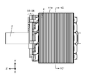
- FIG. 1A is a top view showing the motor 1 according to the first embodiment.
- FIG. 1B is a side view showing motor 1 according to the first embodiment.
- FIG. 1C is a sectional view taken along line 1C-1C in FIG. 1B.
- insulators such as a cover case and an insulator are not shown.
- the motor 1 includes a shaft 2, a rotor 3, a stator 4, an insulator (not shown), stator coils U11, U22, U32, U41, V12, V21, V31 inside a cover case (not shown). , V42, W11, W22, W32, W41, and bus bars 51 to 54.
- the longitudinal direction of the shaft 2 (the direction perpendicular to the plane of FIG. 1A) is referred to as the Z-axis direction, and the direction perpendicular thereto (the direction parallel to the plane of FIG. 1A) is referred to as the X-axis direction and the Y-axis direction. I do.
- the X-axis direction and the Y-axis direction are orthogonal.
- “Integrally” or “integrally” means that a plurality of parts are not only mechanically connected by bolting or caulking, but also by material bonding such as covalent bonding, ionic bonding, and metal bonding. Refers to the state of one electrically connected object or the one electrically connected state in which the whole part is material-bonded by melting or the like.
- the rotor 3 is provided in contact with the outer periphery of the shaft 2, and includes a magnet 31 having N poles and S poles arranged alternately along the outer periphery of the shaft 2 so as to face the stator 4.
- a neodymium magnet is used as the magnet 31, but the material, shape, and material thereof can be appropriately changed according to the output of the motor and the like.
- the stator 4 has a substantially annular stator core 41, a plurality of teeth 42 provided at equal intervals along the inner circumference thereof, and slots 43 provided between the teeth 42, respectively.
- the stator 4 is disposed outside the rotor 3 at a certain interval from the rotor 3 when viewed from the Z-axis direction.
- the stator core 41 is configured as an aggregate of a plurality of core segments.
- the aspect of the core segment in the present embodiment is an aspect including a yoke 44 and a plurality of teeth 42.
- a suitable aspect can be appropriately selected in addition to the example described in the present embodiment.
- the yoke 44 of the present embodiment has a single annular shape, a configuration in which a plurality of sector-shaped core segments are formed and the plurality of sector-shaped core segments are arranged in an annular shape is also possible. good.
- the stator core 41 and each core segment are formed by laminating a plurality of core sheets (stator core sheets 41a) formed by punching an electromagnetic steel sheet containing, for example, silicon or the like into a predetermined shape. It is.
- the number of magnetic poles of the rotor 3 is 5 N poles facing the stator 4 and 5 S poles, that is, 10 poles in total, and the number of slots 43 is 12.
- the present invention is not particularly limited to this, and other combinations of the number of magnetic poles and the number of slots are also applicable.
- the stator 4 has twelve stator coils U11, U22, U32, U41, V12, V21, V31, V42, W11, W22, W32, W41. These stator coils are mounted on the respective teeth 42 and are disposed in the respective slots 43 when viewed from the Z-axis direction. That is, the stator coils U11, U22, U32, U41, V12, V21, V31, V42, W11, W22, W32, and W41 are wound around the teeth 42 in a concentrated manner.
- stator coils U11, U22, U32, and U41 are arranged integrally with the bus bar 51, the stator coils V12, V21, V31, and V42 are integrated with the bus bar 52, and the stator coils W11, W22, W32, and W41 are integrated with the bus bar 53, respectively.
- the bus bar may or may not be configured, and may be connected by a connection board, a lead wire, or the like.
- the first characters represent the respective phases of the motor 1 (in the present embodiment, U-phase, V-phase and W-phase).
- the second character indicates the order of arrangement of the stator coils in the same phase.
- the third character indicates the direction of rotation of the spiral coil serving as the stator coil.
- 1 is a clockwise direction and 2 is a counterclockwise direction. Therefore, the stator coil U11 indicates that the arrangement order of the U-phase is the first stator coil, and the circumferential direction is the clockwise direction.
- the stator coil V42 is the fourth stator coil in the V-phase arrangement order, and indicates that the winding direction is the counterclockwise direction. Note that clockwise means clockwise as viewed from the center of the motor 1, and "counterclockwise” means counterclockwise as viewed from the center of the motor 1.
- stator coils U11 and U41 are U-phase stator coils, and the stator coils U22 and U32 are U-bar phase (the direction of the generated magnetic field is opposite to that of the U-phase stator coil).
- U-phase stator coils are collectively referred to unless otherwise specified.
- stator coils V12, V21, V31, and V42 and the stator coils W11, W22, W32, and W41 are collectively referred to as a V-phase stator coil and a W-phase stator coil, respectively.
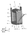
- FIG. 2 is a perspective view showing the stator coil 5 according to the first embodiment.
- the stator coil 5 is applied to the stator coils U11, U22, U32, U41, V12, V21, V31, V42, W11, W22, W32, W41 mounted on the teeth 42 of the motor 1 shown in FIG. 1C.
- the stator coil 5 has a helical structure including an annular body 5m having a predetermined number of turns.
- the annular body 5m is a mode that forms a spiral coil having a laminated structure. As shown in FIG. 2, the shape of each turn of the annular body 5m is substantially rectangular in plan view.
- the long side of the short shape of the annular body 5m in plan view is located on each of the teeth stacking surface sides and is referred to as a coil line portion 5q.
- the shorter side of the short shape of the annular body 5m in plan view is located between the same-direction ends of the coil line portion 5q, which is a pair of longer sides, and is referred to as a coil end 5r.
- a portion that transitions from one end of the coil line portion 5q to one end of the coil end portion 5r is referred to as a coil corner portion 5s.
- the stator coil 5 which is a helical coil, includes a conducting wire portion 5a, an insulating coating 5b provided on the surface of the conducting wire portion 5a, and a lead portion 5c drawn from the first turn and the tenth turn of the stator coil 5, respectively. And a drawer 5d.
- the annular body 5m of the second to tenth turns of the stator coil 5 has a substantially rectangular annular shape in plan view.
- Each of the annular bodies 5m of the second to tenth turns of the stator coil 5 has two short sides, two long sides, and four coil corners 5s. In FIG. 2, each of the annular bodies 5m from the first turn to the ninth turn makes one round in an annular shape.
- the tenth turn is a mode in which the annular shape is less than one round, and one short side of the annular body 5m is not enough.
- the tenth turn is a mode in which the annular shape is less than about a quarter turn, and is substantially three quarters (3/4 turn).
- the reason that the tenth turn is less than about a quarter turn is due to the arrangement of the drawer 5c and the drawer 5d. Depending on the arrangement of the drawer 5c and the drawer 5d, it may be possible to consider that the tenth turn satisfies one turn or that the turn turns slightly more than one turn. Similarly, the first turn may be less than one turn, or may be slightly more than one turn.
- the conductor 5a has a conductor having a square cross section and an insulating coating 5b covering the conductor.
- the conducting wire portion 5a is a structure in which an annular structure is spirally stacked.
- the spirally stacked mode is a structure in which the motor is stacked in a radially inward and outward direction, and includes an annular body 5m having a predetermined number of turns.
- the predetermined number of turns includes the first to n-th turns (n is an integer of 2 or more). Note that the first to n-th turns are referred to as a turn sequence.
- the conducting wire portion 5a is a wire made of a conductive member having a substantially rectangular cross section, and constitutes a turn row in which a single-layered 10-turn annular body 5m is spirally stacked.
- the conducting wire portion 5a is made of, for example, copper, aluminum, zinc, magnesium, brass, iron, SUS (Steel Use Stainless Steel), or the like.
- the conductor portion 5a is described as a single-layer coil, the present invention is applicable not only to a single-layer coil but also to a multilayer coil.
- the part wound from the tip of the drawer 5c to a position below the position where the drawer 5d is provided is referred to as a first turn, and the parts wound one turn at a time thereafter are referred to as a second turn. , The third turn,..., The tenth turn.
- the starting point of each turn can be arbitrarily determined.
- the side of the stator coil 5 where the first turn is provided is referred to as “outside”, and the side where the tenth turn is provided is referred to as “inside”. This is because the outside of the motor is defined as “outside” and the center side of the motor is defined as “inside” in the radial direction of the motor structure.
- the insulating coating 5b is provided on the entire surface of the conductive wire portion 5a so as to insulate the stator coil 5 from an external member (not shown).
- the stator coil 5 is insulated from the stator core 41 and the teeth 42 by the insulating coating 5b and an insulating member (not shown) such as insulating paper.
- the adjacent turns in the stator coil 5 are insulated by the insulating coating 5b.
- the insulating film 5b is formed of, for example, polyimide, nylon, PEEK (polyetheretherketone), acryl, amide imide, ester imide, enamel, heat resistant resin, or the like.
- the thickness of the insulating coating 5b is about several tens of ⁇ m, for example, between 5 ⁇ m and 50 ⁇ m.
- Each of the drawer 5c and the drawer 5d is a part of the conductor 5a.
- the lead portion 5c and the lead portion 5d are located outside the side surface of the stator coil 5, in other words, the plane intersecting the turn train of the conductor portion 5a, in order to receive an external current supply or supply an external current. Extends.
- the insulating coating 5b is removed from the lead portions 5c and 5d. The insulating coating 5b does not need to be removed in the entire region of the lead-out portion 5c and the lead-out portion 5d. For example, only the portions necessary for connection with the bus bars 51, 52, 53, and 54 are provided. Should just be removed.
- FIG. 11A is a perspective view showing a conventional stator coil.
- FIG. 11B is a cross-sectional view showing a conventional stator coil.
- the stator coils are neatly arranged and a large cross-sectional area of the copper material can be secured, the copper loss can be reduced.
- the effect of cooling from outside with air, refrigerant, oil, or the like is limited because the gap between the stator coils or the area in contact with the cooling material is small.
- each of the outer peripheral portion of the coil end portion 5r, each of the outer peripheral portion of the coil line portion 5q, and the coil corner portion This is an aspect including a plurality of concave portions that are concave with respect to the virtual envelope surface including each of the outer peripheral portions of 5s.
- the position where each of the plurality of concave portions is arranged is on the side of the coil end portion 5r which is the short side of the stator coil 5 in the spiral coil.
- the outer periphery of the coil end 5r and the outer periphery of the coil corner 5s of the one-turn annular body are located.
- the width of the stator coil in the concave portions 5e and 5f is narrower by about ⁇ ⁇ to ⁇ ⁇ than the width of the stator coil of the annular body which is a turn adjacent to the concave portions 5e and 5f.
- the mode of the coil corner portion 5s in the concave portion 5e and the concave portion 5f adopts a suitable shape that does not hinder the flow of air or refrigerant.
- the width of the stator coil in the concave portions 5e and 5f is limited to a mode having a width that is narrower by about 1/5 to 1/2 than the stator coil width of the annular body which is a turn adjacent to the concave portions 5e and 5f. Not something.
- a suitable stator coil width can be selected in consideration of matters such as a reduction in the rigidity of the stator coil and an increase in Joule heat due to an increase in resistance in the stator coil conductor.
- the concave portion 5 e and the concave portion 5 f are arranged in each of the upper portion which is the coil end and the lower portion which is the coil end of the stator coil 5.
- a mode in which 5e or the concave portion 5f is arranged may be used. Arranging the recess every other turn may have a greater effect of increasing the surface area of the stator coil, and may secure a flow path for air, refrigerant, or the like, and may thus increase the cooling effect.
- the shape of the coil corner portion 5s shown in FIG. 2 largely depends on the machining accuracy of the annular body 5m itself in the stator coil 5. For this reason, R chamfering, C chamfering, etc. may be arranged on the outer peripheral portion of the coil corner portion 5s. By arranging R chamfering or C chamfering or the like, the outer peripheral portion of the annular body 5m may have a polygonal shape or a shape having R portions at four corners in plan view.
- the number of turns of the stator coil 5 is set to 10.
- the present invention is not particularly limited to this, and other values may be used.
- the motor 1 of the present embodiment includes at least the stator core 41 including the stacked body in which the plurality of stator core sheets 41a are stacked, and the stator coil 5 having the teeth 42 included in the stator core 41 as a part of the magnetic core. And a rotor 3 rotatably supported via the tip of the teeth 42 of the stator core 41 and a gap.
- the stator coil 5 constitutes a spiral coil including an annular body 5m having a predetermined number of turns.
- the annular body 5m includes a conductor 5a, and the conductor 5a is a conductor and an insulating coating 5b covering the conductor.
- the cross-sectional shape of the conductor portion is substantially square, and a part of the annular body 5m located on each of the lamination surface sides of the teeth 42 is defined as a coil line part 5q, and a part of the annular body 5m A portion located between the same-direction ends of the paired coil line portions 5q is defined as a coil end portion 5r, and a portion transitioning from one end of the coil line portion 5q to one end of the coil end portion 5r is defined.
- a concave portion 5e which is defined as a coil corner portion 5s and which is recessed with respect to a virtual envelope including an outer peripheral portion of the coil end portion 5r, an outer peripheral portion of the coil line portion 5q, and an outer peripheral portion of the coil corner portion 5s in the spiral coil. , 5f less To one comprising both.
- the stator coil in the motor of the present invention has a structure in which a heat radiation area for air, refrigerant, oil, and the like is increased as compared with the stator coil illustrated as a conventional example.
- a structure is provided in which circulation paths for air, refrigerant, oil, and the like are increased.
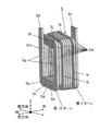
- FIG. 3 is a perspective view showing the stator coil 5 according to the second embodiment.
- the configuration of the motor according to the second embodiment is the same as that of the first embodiment, and a description of the same content is omitted.
- the outer peripheral portion of the coil end portion 5r, the outer peripheral portion of the coil line portion 5q, and the outer peripheral portion of the coil corner portion 5s are formed.
- a plurality of recesses 5g and recesses 5h that are recessed with respect to the included virtual envelope surface are provided.
- the position where each of the plurality of concave portions is arranged is on the side of the coil line portion 5q which is the long side of the stator coil 5 in the stator coil 5 which is a spiral coil.
- ⁇ ⁇ Includes a mode in which the outer periphery of the one-turn annular coil line portion 5q and the outer periphery of the coil corner 5s are located at the bottom of the recess 5g, which is one of the plurality of recesses.
- the width of the stator coil in the concave portions 5g and 5h is narrower by about 1/5 to 1/2 than the stator coil width of the annular body which is a turn adjacent to the concave portions 5g and 5h.
- the mode of the coil corner portion 5s in the concave portions 5g and 5h adopts a suitable shape that does not hinder the flow of air or refrigerant.
- the width of the stator coil in the concave portion 5g and the concave portion 5h is not limited to an embodiment having a width that is about ⁇ to 5 smaller than the stator coil width of the annular body that is the turn adjacent to the concave portion 5g and the concave portion 5h. Absent.
- a suitable stator coil width can be selected in consideration of matters such as a reduction in the rigidity of the stator coil and an increase in Joule heat due to an increase in resistance in the stator coil conductor.
- the concave portion 5g and the concave portion 5h are arranged in each of the coil line portions 5q on the long side of the stator coil 5.
- the present invention is not limited to this mode, and a mode in which the concave portion 5g or the concave portion 5h is arranged every other turn may be used.
- the arrangement of the recesses every other turn has a greater effect of increasing the surface area of the stator coil. Thereby, a flow path for air or a refrigerant can be secured. For this reason, the cooling effect may increase.
- the outer peripheral portion of the coil line portion 5 q and the coil corner portion 5 s of the annular body having a plurality of turns adjacent to each other are provided at the bottom of the concave portion.
- An aspect in which the outer peripheral portion is located may be used.
- the outer peripheral portion of the coil line portion 5 q and the coil corner portion 5 s of the one-turn annular body are provided at the bottom of the concave portion.
- An aspect in which the outer peripheral portion is located may be used.
- FIG. 10D a mode in which a plurality of concave portions shown in FIG. 10D, FIG. 10E, or FIG. 10F may be included.
- an R chamfer or a C chamfer is arranged on the outer periphery of the coil corner 5s. May be.
- the outer peripheral portion of the annular body 5m may have a polygonal shape or a shape having R portions at four corners in plan view.
- a mode in which fine relief grooves are arranged may be adopted from the viewpoint of processing easiness in processing the annular body 5m itself in the stator coil 5.
- the number of turns of the stator coil 5 is set to 10. However, the present invention is not particularly limited to this, and other values may be used. In addition, the number of turns of the stator coil 5 shown in the drawing is a value slightly less than 10 when accurately described.
- each of the annular bodies 5m makes one round in an annular shape from the first turn to the ninth turn.
- the annular shape is less than one round, and the short side of the annular body 5m is less than one short side. In other words, the tenth turn is a mode in which the annular shape is substantially three quarters (3/4) less than about one quarter. .
- the tenth turn is less than about a quarter turn is due to the arrangement of the drawer 5c and the drawer 5d.
- the tenth turn may satisfy one turn, or may turn slightly more than one turn.
- the first turn may be less than one turn, or may be slightly more than one turn.
- the motor 1 of the present embodiment includes at least the stator core 41 including the stacked body in which the plurality of stator core sheets 41a are stacked, and the stator coil 5 having the teeth 42 included in the stator core 41 as a part of the magnetic core.
- the stator 4 includes a rotor 4 rotatably supported via the tip of the teeth 42 of the stator core 41 and a gap.
- the stator coil 5 constitutes a spiral coil including an annular body 5m having a predetermined number of turns.
- the annular body includes a conductor 5a, and the conductor 5a includes a conductor and an insulating coating 5b covering the conductor.
- the cross-sectional shape of the conductor portion is substantially rectangular, and a part of the annular body 5m located on each of the lamination surface sides of the teeth 42 is defined as a coil line part 5q, and is a part of the annular body 5m.
- a portion located between the ends of the pair of coil line portions 5q in the same direction is defined as a coil end portion 5r, and a portion that transitions from one end of the coil line portion 5q to one end of the coil end portion 5r is a coil.
- a plurality of concave portions are depressed with respect to the virtual envelope surface including the outer peripheral portion of the coil end portion 5r, the outer peripheral portion of the coil line portion 5q, and the outer peripheral portion of the coil corner portion 5s.
- Recess 5g, 5 Comprising a The plurality of recesses 5g, 5h are located on the side of the coil line portion 5q in the helical coil, and at least one of the plurality of recesses 5g, 5h is provided at the bottom of the recess in a one-turn annular coil line portion 5q. And the outer periphery of the coil corner 5s.
- At least another of the plurality of recesses 5g and 5h has, at the bottom of the recess, an outer peripheral portion of the coil line portion 5q and an outer peripheral portion of the coil corner portion 5s of the annular body 5m having a plurality of turns adjacent to each other. .
- the stator coil in the motor of the present invention has a structure in which a heat radiation area for air, refrigerant, oil, and the like is increased as compared with the stator coil illustrated as a conventional example.
- a structure is provided in which circulation paths for air, refrigerant, oil, and the like are increased.
- fluids such as air, refrigerant, and oil pass through a gap (oil passage) near the stator coil from the upstream side of the flow, pass downstream of the flow, and further smoothly circulate, increasing the heat radiation effect. It becomes possible.
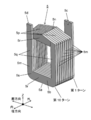
- FIG. 4 is a perspective view showing a stator coil 5 according to the third embodiment.
- the configuration of the motor in the third embodiment is the same as that in the first embodiment, and the description of the same content will be omitted.
- the outer peripheral portion of the coil end portion 5r, the outer peripheral portion of the coil line portion 5q, and the outer peripheral portion of the coil corner portion 5s are formed. It is an aspect provided with a plurality of concave portions that are depressed with respect to the virtual envelope surface. That is, the position where each of the plurality of recesses is arranged extends over one circumference of the outer peripheral surface of the stator coil 5 in the spiral coil.
- the outer periphery of the coil line portion 5q, the outer periphery of the coil end portion 5r, and the outer periphery of the coil corner portion 5s, which are adjacent to each other, are provided on the bottom of the recess 5j, which is another one of the plurality of recesses. Department is located.
- the width of the stator coil in the concave portions 5i and 5j is narrower by about 5 to ⁇ than the width of the stator coil of the annular body which is a turn adjacent to the concave portions 5i and 5j. Further, according to the mode of reducing the stator coil width, the mode of the coil corner portion 5s in the concave portion 5i and the concave portion 5j adopts a suitable shape that does not hinder the flow of air or refrigerant.
- the width of the stator coil in the concave portions 5i and 5j is limited to a mode having a width that is narrower by about ⁇ ⁇ to ⁇ ⁇ than the stator coil width of the annular body which is a turn adjacent to the concave portions 5i and 5j. Not something.
- a suitable stator coil width can be selected in consideration of matters such as a reduction in the rigidity of the stator coil and an increase in Joule heat due to an increase in resistance in the stator coil conductor.
- the concave portion 5i and the concave portion 5j are arranged over one circumference of the stator coil 5.
- the present invention is not limited to this mode, and a mode in which the concave portion 5i or the concave portion 5j is arranged every other turn may be used.
- the arrangement of the recesses every other turn has a greater effect of increasing the surface area of the stator coil. Thereby, a flow path for air, refrigerant, and the like can be secured. Therefore, the cooling effect may be enhanced.
- the outer peripheral portion of the coil line portion 5 q and the coil corner portion 5 s of the annular body having a plurality of turns adjacent to each other are provided at the bottom of the concave portion.
- An aspect in which the outer peripheral portion is located may be used.
- the outer peripheral portion of the coil line portion 5 q and the coil corner portion 5 s of the one-turn annular body are provided at the bottom of the concave portion.
- An aspect in which the outer peripheral portion is located may be used.
- an R chamfer or a C chamfer is arranged on the outer periphery of the coil corner 5s. May be.
- the outer peripheral portion of the annular body 5m may have a polygonal shape or a shape having R portions at four corners in plan view.
- a mode in which fine relief grooves are arranged may be adopted from the viewpoint of processing easiness in processing the annular body 5m itself in the stator coil 5.
- the number of turns of the stator coil 5 is set to 10. However, the present invention is not particularly limited to this, and other values may be used. In addition, the number of turns of the stator coil 5 shown in the drawing is a value slightly less than 10 when accurately described.
- each of the annular bodies 5m makes one round in an annular shape from the first turn to the ninth turn.
- the annular shape is less than one round, and the short side of the annular body 5m is less than one short side. In other words, the tenth turn is a mode in which the annular shape is substantially three quarters (3/4) less than about one quarter. .
- the tenth turn is less than about a quarter turn is due to the arrangement of the drawer 5c and the drawer 5d.
- the tenth turn may satisfy one turn, or may turn slightly more than one turn.
- the first turn may be less than one turn, or may be slightly more than one turn.
- the stator coil in the motor of the present invention has a structure in which a heat radiation area for air, refrigerant, oil, and the like is increased as compared with the stator coil illustrated as a conventional example.
- a structure is provided in which circulation paths for air, refrigerant, oil, and the like are increased.
- a fluid such as air, refrigerant, or oil passes through a gap (oil passage) near the stator coil from the upstream side of the flow, passes downstream of the flow, and further smoothly circulates. Therefore, the heat radiation effect can be enhanced.
- FIG. 5 is a perspective view showing a stator coil 5 according to the fourth embodiment.
- the configuration of the motor in the fourth embodiment is the same as that in the first embodiment, and the description of the same content will be omitted.
- the outer peripheral portion of the coil end portion 5r, the outer peripheral portion of the coil line portion 5q, and the outer peripheral portion of the coil corner portion 5s are formed. It is an aspect provided with a plurality of concave portions that are depressed with respect to the virtual envelope surface. That is, the position where each of the plurality of recesses is arranged extends over one circumference of the outer peripheral surface of the stator coil 5 in the spiral coil.
- the outer periphery of the coil line portion 5q, the outer periphery of the coil end portion 5r, and the outer periphery of the coil corner portion 5s, which are adjacent to each other, are provided on the bottom of the recess 5j, which is another one of the plurality of recesses. Department is located.
- the width of the stator coil in the concave portions 5i and 5j is narrower by about 5 to ⁇ than the width of the stator coil of the annular body which is a turn adjacent to the concave portions 5i and 5j.
- the mode of the coil corner portion 5s in the concave portion 5i and the concave portion 5j adopts a suitable shape that does not hinder the flow of air or refrigerant.
- the width of the stator coil in the concave portions 5i and 5j is limited to a mode having a width that is narrower by about ⁇ ⁇ to ⁇ ⁇ than the stator coil width of the annular body which is a turn adjacent to the concave portions 5i and 5j. Not something.
- a suitable stator coil width can be selected in consideration of matters such as a reduction in the rigidity of the stator coil and an increase in Joule heat due to an increase in resistance in the stator coil conductor.
- the recess 5i and the recess 5j are arranged over the entire circumference of the stator coil 5, but the present invention is not limited to this, and the recess 5i or the recess 5j may be arranged every other turn. . In some cases, the arrangement of the recesses every other turn has a greater effect of increasing the surface area of the stator coil. Thereby, a flow path for air or a refrigerant can be secured. Therefore, the cooling effect may be enhanced.
- the outer peripheral portion and the coil corner portion 5s of the coil line portion 5q provided in the annular body having a plurality of turns adjacent to each other are provided at the bottom of the plurality of concave portions. In which the outer peripheral portion is located.
- the outer peripheral portion and the coil corner portion 5s of the coil line portion 5q provided in the one-turn annular body are provided at the bottom of the plurality of recesses. In which the outer peripheral portion is located.
- the shape of the coil corner portion 5s shown in FIG. 5 largely depends on the processing accuracy of the annular body 5m itself in the stator coil 5. For this reason, R chamfering, C chamfering, etc. may be arranged on the outer peripheral portion of the coil corner portion 5s. By arranging R chamfering or C chamfering or the like, the outer peripheral portion of the annular body 5m may have a polygonal shape or a shape having R portions at four corners in plan view.
- a mode in which fine relief grooves are arranged may be adopted from the viewpoint of processing easiness in processing the annular body 5m of the stator coil 5 itself.
- the number of turns of the stator coil 5 is set to 10. However, the present invention is not particularly limited to this, and other values may be used. In addition, the number of turns of the stator coil 5 shown in the drawing is a value slightly less than 10 when accurately described.
- each of the annular bodies 5m makes one round in an annular shape from the first turn to the ninth turn.
- the annular shape is less than one round, and the short side of the annular body 5m is less than one short side. In other words, the tenth turn is a mode in which the annular shape is substantially three quarters (3/4) less than about one quarter. .
- the tenth turn is less than about a quarter turn is due to the arrangement of the drawer 5c and the drawer 5d.
- the tenth turn may satisfy one turn, or may turn slightly more than one turn.
- the first turn may be less than one turn, or may be slightly more than one turn.
- the groove-shaped concave portion 5k and the concave portion 51 communicating with each other from the start turn to the end turn are provided.
- the longitudinal directions of the groove-like shapes of the recesses cross each other between different recesses among the plurality of recesses. That is, the longitudinal direction of the groove shape of the concave portions in the concave portions 5k and 51 is substantially orthogonal to the longitudinal direction of the groove shape of the concave portions in the concave portions 5i and 5j.
- the cross-sectional shape of the communicating groove-shaped concave portions 5k and 5l is exemplified by a quadrangle as a substantial shape.
- the cross-sectional shape of the groove is not limited to this, and may be any shape such as a triangular shape as a substantial shape, a semicircular shape as a substantial shape, or a trapezoidal shape as a substantial shape.
- the location to be provided may be any one of the four surfaces of the envelope surface of the stator coil, and a suitable location is appropriately selected.
- the stator coil in the motor of the present invention has a structure in which a heat radiation area for air, refrigerant, oil, and the like is increased as compared with the stator coil illustrated as a conventional example.
- a structure is provided in which circulation paths for air, refrigerant, oil, and the like are increased.
- Fluids such as air, refrigerant, oil, etc., pass from the upstream side of the flow through the gap (oil passage) near the stator coil, pass through the downstream side of the flow, and furthermore, the circulation is smooth, and the heat radiation effect can be enhanced. It becomes possible.
- FIG. 6 is a perspective view showing a stator coil 5 according to the fifth embodiment.
- the configuration of the motor according to the fifth embodiment is the same as that of the first embodiment, and a description of the same content is omitted.
- the stator coil 5 which is a spiral coil shown in FIG. 6 has predetermined virtual envelope surfaces including an outer peripheral portion of the coil end portion 5r, an outer peripheral portion of the coil line portion 5q, and an outer peripheral portion of the coil corner portion 5s. From the start turn to the end turn of the set number of turns, the center part of the coil end portion is set as a ridgeline 5n, and a slope 5p descending from the ridgeline 5n to each coil corner portion 5s is provided.
- the slope 5p illustrates a flat surface.
- the aspect of the slope 5p is not limited to this, and may be a convex curved surface, a concave curved surface, a composite inclined surface including a plurality of different inclination angles, or any functional curved surface, and is not particularly limited.
- the slope 5p is a mode in which the slope is arranged only on one side of the coil end portion 5r of the stator coil 5 which is a spiral coil.
- a mode in which a slope is arranged on each of the two coil end portions 5r may be used. Not limited.
- the number of turns of the stator coil 5 was set to 10. However, the present invention is not particularly limited to this, and other values may be used. In addition, the number of turns of the stator coil 5 shown in the drawing is a value slightly less than 10 when accurately described.
- each of the annular bodies 5m makes one round in an annular shape from the first turn to the ninth turn.
- the annular shape is less than one round, and the short side of the annular body 5m is less than one short side.
- the tenth turn is a mode in which the annular shape is substantially three quarters (3/4) less than about one quarter. .
- the tenth turn is less than about a quarter turn is due to the arrangement of the drawer portions 5c and 5d.
- the tenth turn may satisfy one turn, or may turn slightly more than one turn.
- the first turn may be less than one turn, or may be slightly more than one turn.
- motor 1 of the present embodiment includes at least stator core 41 including a stacked body in which a plurality of stator core sheets 41a are stacked, and stator coil 5 having teeth provided on stator core 41 as a part of the magnetic core. It includes a stator 4 and a rotor 3 that is rotatably supported via the tip of the teeth 42 of the stator core 41 and a gap.
- the stator coil 5 constitutes a spiral coil including an annular body 5m having a predetermined number of turns.
- the annular body 5m includes a conductor 5a, and the conductor 5a is a conductor and an insulating coating 5b covering the conductor.
- the cross-sectional shape of the conductor portion is substantially square, and a part of the annular body 5m located on each of the lamination surface sides of the teeth 42 is defined as a coil line part 5q, and a part of the annular body 5m A portion located between the ends of the paired coil line portions 5m in the same direction is defined as a coil end portion 5r, and a portion transitioning from one end of the coil line portion 5q to one end of the coil end portion 5r is defined.
- a predetermined predetermined value is set on a virtual envelope surface including an outer peripheral portion of the coil end portion 5r, an outer peripheral portion of the coil line portion 5q, and an outer peripheral portion of the coil corner portion 5s.
- the stator coil in the motor of the present invention has a structure in which a heat radiation area for air, refrigerant, oil, and the like is increased as compared with the stator coil illustrated as a conventional example.
- a structure is provided in which circulation paths for air, refrigerant, oil, and the like are increased.
- Fluids such as air, refrigerant, oil, etc., pass from the upstream side of the flow through the gap (oil passage) near the stator coil, pass through the downstream side of the flow, and furthermore, the circulation is smooth, and the heat radiation effect can be enhanced. It becomes possible.
- FIG. 7 is a perspective view showing a stator coil 5 according to the sixth embodiment.
- the configuration of the motor according to the sixth embodiment is the same as that of the first embodiment, and a description of the same content will be omitted.
- the configuration of the stator coil 5 in the sixth embodiment is substantially the same as that in the first embodiment, and a description of the same content will be omitted.
- the stator coil 5 which is a spiral coil shown in FIG. 7, has a predetermined shape on a virtual envelope surface including an outer peripheral portion of the coil end portion 5r, an outer peripheral portion of the coil line portion 5q, and an outer peripheral portion of the coil corner portion 5s. From the start turn to the end turn of the set number of turns, the center of the coil end portion is defined as a ridgeline 5n, and a slope 5p descending from the ridgeline 5n to each of the coil corner portions 5s is provided.
- the slope 5p illustrates a flat surface.
- the aspect of the slope 5p is not limited to this, and may be a convex curved surface, a concave curved surface, a composite inclined surface including a plurality of different inclination angles, or any functional curved surface, and is not particularly limited.
- the slope 5p is a mode in which the slope 5p is arranged only on one side of the coil end portion 5r of the stator coil 5 which is a spiral coil, but a mode in which the slope 5p is arranged in each of both coil end portions 5r may be adopted. There is no particular limitation.
- the stator coil in the motor of the present invention has a structure in which a heat radiation area for air, refrigerant, oil, and the like is increased as compared with the stator coil illustrated as a conventional example.
- a structure is provided in which circulation paths for air, refrigerant, oil, and the like are increased.
- Fluids such as air, refrigerant, oil, etc., pass from the upstream side of the flow through the gap (oil passage) near the stator coil, pass through the downstream side of the flow, and furthermore, the circulation is smooth, and the heat radiation effect can be enhanced. It becomes possible.
- FIG. 8 is a perspective view showing a stator coil 5 according to the seventh embodiment.
- the configuration of the motor in the seventh embodiment is the same as that in the first embodiment, and a description of the same content will be omitted.
- the configuration of the stator coil 5 in the seventh embodiment is almost the same as that in the first embodiment, and a description of the same content will be omitted.
- the stator coil 5 which is a spiral coil shown in FIG. 8 has a predetermined predetermined shape on a virtual envelope surface including an outer peripheral portion of the coil end portion 5r, an outer peripheral portion of the coil line portion 5q, and an outer peripheral portion of the coil corner portion 5s. From the start turn to the end turn of the set number of turns, the center of the coil end portion is defined as a ridgeline 5n, and a slope 5p descending from the ridgeline 5n to each of the coil corner portions 5s is provided.
- the slope 5p illustrates a flat surface.
- the aspect of the slope 5p is not limited to this, and may be a convex curved surface, a concave curved surface, a composite inclined surface including a plurality of different inclination angles, or any functional curved surface, and is not particularly limited.
- the slope 5p is a mode in which the slope 5p is arranged only on one side of the coil end portion 5r of the stator coil 5 which is a spiral coil, but a mode in which the slope 5p is arranged in each of both coil end portions 5r may be adopted. There is no particular limitation.
- the number of turns of the stator coil 5 was set to 10. However, the present invention is not particularly limited to this, and other values may be used. In addition, the number of turns of the stator coil 5 shown in the drawing is a value slightly less than 10 when accurately described.
- the stator coil 5 shown in FIG. 8 is configured such that each of the annular bodies 5m makes one round in an annular shape from the first turn to the ninth turn. On the other hand, in the tenth turn, the annular shape is less than one round, and the short side of the annular body 5m is less than one short side. In other words, the tenth turn is a mode in which the annular shape is substantially three quarters (3/4) less than about one quarter. .
- the tenth turn is less than about a quarter turn is due to the arrangement of the drawer portions 5c and 5d.
- the tenth turn may satisfy one turn, or may turn slightly more than one turn.
- the first turn may be less than one turn, or may be slightly more than one turn.
- the stator coil in the motor of the present invention has a structure in which a heat radiation area for air, refrigerant, oil, and the like is increased as compared with the stator coil illustrated as a conventional example.
- a structure is provided in which circulation paths for air, refrigerant, oil, and the like are increased.
- Fluids such as air, refrigerant, oil, etc., pass from the upstream side of the flow through the gap (oil passage) near the stator coil, pass through the downstream side of the flow, and furthermore, the circulation is smooth, and the heat radiation effect can be enhanced. It becomes possible.
- FIG. 9 is a perspective view showing a stator coil 5 according to the eighth embodiment.
- the configuration of the motor according to the eighth embodiment is the same as that of the first embodiment, and the description of the same content is omitted.
- the configuration of the stator coil 5 according to the eighth embodiment is substantially the same as that of the third embodiment, and a description of the same content will not be repeated.
- the stator coil 5, which is a spiral coil shown in FIG. 9, has a predetermined predetermined shape on a virtual envelope including an outer peripheral portion of the coil end portion 5r, an outer peripheral portion of the coil line portion 5q, and an outer peripheral portion of the coil corner portion 5s. From the start turn to the end turn of the set number of turns, the center of the coil end portion is defined as a ridgeline 5n, and a slope 5p descending from the ridgeline 5n to each of the coil corner portions 5s is provided.
- the slope 5p is a mode in which the slope 5p is arranged only on one side of the coil end portion 5r of the stator coil 5 which is a spiral coil, but a mode in which the slope 5p is arranged in each of both coil end portions 5r may be adopted. There is no particular limitation.
- the slope 5p illustrates a flat surface.
- the aspect of the slope 5p is not limited to this, and may be a convex curved surface, a concave curved surface, a composite inclined surface including a plurality of different inclination angles, or any functional curved surface, and is not particularly limited.
- the number of turns of the stator coil 5 was set to 10. However, the present invention is not particularly limited to this, and other values may be used. In addition, the number of turns of the stator coil 5 shown in the drawing is a value slightly less than 10 when accurately described.
- the stator coil 5 shown in FIG. 8 is configured such that each of the annular bodies 5m makes one round in an annular shape from the first turn to the ninth turn. On the other hand, in the tenth turn, the annular shape is less than one round, and the short side of the annular body 5m is less than one short side. In other words, the tenth turn is a mode in which the annular shape is substantially three quarters (3/4) less than about one quarter. .
- the tenth turn is less than about a quarter turn is due to the arrangement of the drawer portions 5c and 5d.
- the tenth turn may satisfy one turn, or may turn slightly more than one turn.
- the first turn may be less than one turn, or may be slightly more than one turn.
- the stator coil in the motor of the present invention has a structure in which a heat radiation area for air, refrigerant, oil, and the like is increased as compared with the stator coil illustrated as a conventional example.
- a structure is provided in which circulation paths for air, refrigerant, oil, and the like are increased.
- Fluids such as air, refrigerant, oil, etc., pass from the upstream side of the flow through the gap (oil passage) near the stator coil, pass through the downstream side of the flow, and furthermore, the circulation is smooth, and the heat radiation effect can be enhanced. It becomes possible.
- FIG. 10A is a sectional view showing the stator coil 5 according to the ninth embodiment.
- FIG. 10B is a sectional view showing another stator coil 5 according to the ninth embodiment.
- FIG. 10C is a sectional view showing another stator coil 5 according to the ninth embodiment.
- FIG. 10D is a sectional view showing another stator coil 5 according to the ninth embodiment.
- FIG. 10E is a sectional view showing another stator coil 5 according to the ninth embodiment.
- FIG. 10F is a sectional view showing another stator coil 5 according to the ninth embodiment.
- the aspect of the stator coil 5 shown in the ninth embodiment shows an aspect that can be applied to the second, third, fourth, seventh, and eighth embodiments. .
- the configuration of the motor in the ninth embodiment is the same as that in the first embodiment, and the description of the same content will be omitted.
- the configuration of the stator coil 5 according to the ninth embodiment is substantially the same as that of the second, third, fourth, seventh, and eighth embodiments. Is omitted from the description.
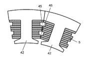
- the total number of turns of the stator coil 5 shown in FIG. 10A is substantially 10.
- the second turn, the third turn, the seventh turn, and the eighth turn are embodiments in which the width of the conductor is smaller than the adjacent turns.
- the oil passage 45 is configured in this manner.
- the total number of turns of the stator coil 5 shown in FIG. 10B is substantially 10.
- the second turn, the fifth turn, and the ninth turn are embodiments in which the width of the conductor is smaller than the adjacent turns. It is considered that the embodiment of the stator coil 5 shown in FIG. 10B can increase the surface area of the stator coil 5 than the embodiment of the stator coil 5 shown in FIG. It is considered to be possible.
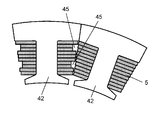
- the total number of turns of the stator coil 5 shown in FIG. 10C is substantially 10.
- the width of the conductor is smaller in the turns of the stator coil located on the tooth tip side than in the preceding and following turns.
- the oil passage 45 is configured in this manner.
- the width of the conductor of the turn of the stator coil located on the tooth tip side is a mode in which the width of the conductor is narrower than the other turns. This is a mode in which the parts to be reduced are also concentratedly arranged. According to this aspect, it is possible to suppress loss and heat generation due to eddy current.
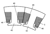
- the stator coil 5 shown in FIGS. 10D and 10E is a mode in which the overall shapes of the adjacent stator coils in the slots of the stator are different from each other.
- the oil passage 45 is configured in this manner. It is important to increase the surface area of the stator coil and to configure the liquid flow path, and it is not necessary that adjacent stator coils have the same shape.
- the overall shape of the adjacent stator coils is different from each other to form a liquid flow path. With this configuration, the cross-sectional area of the conductor is specified within an allowable range, and the flow path is secured while reducing the Joule loss of the conductor. This makes it possible to suppress heat generation and enhance the cooling effect.
- the stator coil 5 shown in FIG. 10F is a mode in which a gap 46 is arranged on the tip side of the tooth 42 and on the inner peripheral side of the stator coil 5 in contact with the tooth 42. According to this aspect, it is possible to effectively reduce the heat generated by the eddy current in the stator coil. Therefore, it contributes to improving the performance of the motor.
- the stator coil in the motor of the present invention has a structure in which a heat radiation area for air, refrigerant, oil, and the like is increased as compared with the stator coil illustrated as a conventional example.
- the structure is such that circulation paths for air, refrigerant, oil and the like are increased.
- Fluids such as air, refrigerant, and oil pass through a gap (oil passage 45) near the stator coil from the upstream side of the flow and pass downstream of the flow. Further, circulation of the fluid becomes smooth. Therefore, the heat radiation effect can be enhanced.
- the stator coil 5 in the present invention can be formed by casting. According to this method, a spiral stator coil can be easily formed from a conductive wire having a large sectional area. It should be noted that the present invention is not limited to the above casting, and may be formed by other methods. For example, it may be formed by cutting from a solid material such as copper, aluminum, zinc, magnesium, iron, SUS (Steel Use Stainless), and brass. Further, the individually molded parts may be formed by welding or joining members into a single unit.
- the stator coil in the motor of the present invention can enhance the cooling performance, and is useful when applied to a motor or power equipment.
Abstract
Description
予め定められたターン数の環状体を含む螺旋状コイルを構成し、環状体に導線部を含み、導線部は導体部と導体部を被覆する絶縁性の被膜を有し且つ導体部の断面形状が実質的に四角形であり、
ティースの積層面側の各々に位置する環状体の一部をコイル線路部と定義し、環状体の一部であり且つ一対を成すコイル線路部の同方向端部の間に位置する部分をコイルエンド部と定義し、コイル線路部の一方端からコイルエンド部の一方端へと移行する箇所をコイルコーナー部と定義し、螺旋状コイルにおいて、コイルエンド部の外周部と、コイル線路部の外周部と、コイルコーナー部の外周部とを含む仮想包絡面に対して凹む凹部を少なくとも一つ具備する。 In order to achieve the object, a motor according to one embodiment of the present invention includes, at least, a stator core including a stacked body in which a plurality of stator core sheets are stacked, and a stator including a stator coil including teeth provided in the stator core as a part of a magnetic core. A rotor including a tip of teeth of a stator core and a rotor rotatably supported via a gap, wherein the stator coil includes:
A spiral coil including an annular body having a predetermined number of turns is formed, the annular body includes a conductor, the conductor has a conductor and an insulating coating covering the conductor, and a cross-sectional shape of the conductor Is substantially square,
A part of the annular body positioned on each side of the tooth stacking surface is defined as a coil line part, and a part that is part of the annular body and located between the same-direction ends of the pair of coil line parts is a coil line part. An end portion is defined, and a transition from one end of the coil line portion to one end of the coil end portion is defined as a coil corner portion. In the spiral coil, the outer periphery of the coil end portion and the outer periphery of the coil line portion are defined. And at least one recessed portion that is recessed with respect to the virtual envelope surface including the portion and the outer peripheral portion of the coil corner portion.
ステータコイルは、予め定められたターン数の環状体を含む螺旋状コイルを構成し、環状体に導線部を含み、導線部は導体部と導体部を被覆する絶縁性の被膜を有し且つ導体部の断面形状が実質的に四角形であり、
ティースの積層面側の各々に位置する環状体の一部をコイル線路部と定義し、環状体の一部であり且つ一対を成すコイル線路部の同方向端部の間に位置する部分をコイルエンド部と定義し、コイル線路部の一方端からコイルエンド部の一方端へと移行する箇所をコイルコーナー部と定義するとき、
螺旋状コイルにおいて、コイルエンド部の外周部と、コイル線路部の外周部と、コイルコーナー部の外周部とを含む仮想包絡面に対して凹む複数の凹部を具備し、
複数の凹部は、螺旋状コイルにおけるコイルエンド側に位置し、
複数の凹部のうち少なくとも一つには、凹部の底部に、1ターンの環状体のコイルエンド部の外周部及びコイルコーナー部の外周部が位置し、
且つ、
複数の凹部のうち少なくとも別の一つには、凹部の底部に、互いに隣接する複数ターンの環状体のコイルエンド部の外周部及びコイルコーナー部の外周部が位置する。 According to another aspect of the present invention, there is provided a motor including at least a stator core including a stacked body in which a plurality of stator core sheets are stacked, a stator including a stator coil having teeth provided in the stator core as a part of a magnetic core, and a stator core including: A motor including a tip of a tooth and a rotor rotatably supported through a gap,
The stator coil constitutes a helical coil including an annular body having a predetermined number of turns, the annular body includes a conductor portion, and the conductor portion has a conductor portion and an insulating coating covering the conductor portion. The cross-sectional shape of the part is substantially square,
A part of the annular body positioned on each side of the tooth stacking surface is defined as a coil line part, and a part that is part of the annular body and located between the same-direction ends of the pair of coil line parts is a coil line part. When defining as the end part, and defining the place transitioning from one end of the coil line part to one end of the coil end part as the coil corner part,
In the spiral coil, an outer peripheral portion of a coil end portion, an outer peripheral portion of a coil line portion, and a plurality of concave portions that are depressed with respect to a virtual envelope surface including an outer peripheral portion of a coil corner portion,
The plurality of recesses are located on the coil end side of the spiral coil,
In at least one of the plurality of recesses, the outer periphery of the coil end portion and the outer periphery of the coil corner portion of the one-turn annular body are located at the bottom of the recess,
and,
In at least another one of the plurality of concave portions, the outer peripheral portion of the coil end portion and the outer peripheral portion of the coil corner portion of the plurality of turns of the annular body adjacent to each other are located at the bottom of the concave portion.
予め定められたターン数の環状体を含む螺旋状コイルを構成し、環状体に導線部を含み、導線部は導体部と導体部を被覆する絶縁性の被膜を有し且つ導体部の断面形状が実質的に四角形であり、ティースの積層面側の各々に位置する環状体の一部をコイル線路部と定義し、環状体の一部であり且つ一対を成すコイル線路部の同方向端部の間に位置する部分をコイルエンド部と定義し、コイル線路部の一方端からコイルエンド部の一方端へと移行する箇所をコイルコーナー部と定義するとき、螺旋状コイルにおいて、コイルエンド部の外周部と、コイル線路部の外周部と、コイルコーナー部の外周部とを含む仮想包絡面に対して凹む複数の凹部を具備し、複数の凹部は、螺旋状コイルにおけるコイル線路部の側に位置し、複数の凹部のうち少なくとも一つは、凹部の底部に、1ターンの環状体のコイル線路部の外周部及びコイルコーナー部の外周部が位置し、
且つ、複数の凹部のうち少なくとも別の一つは、凹部の底部に、互いに隣接する複数ターンの環状体のコイル線路部の外周部及びコイルコーナー部の外周部が位置する。 According to still another aspect of the present invention, there is provided a motor including at least a stator core including a stacked body in which a plurality of stator core sheets are stacked, a stator including a stator coil having teeth provided on the stator core as a part of a magnetic core, and a stator core. A rotor rotatably supported via a gap and a tip of the teeth of the motor, the stator coil,
A spiral coil including an annular body having a predetermined number of turns is formed, the annular body includes a conductor, the conductor has a conductor and an insulating coating covering the conductor, and a cross-sectional shape of the conductor Are substantially rectangular, and define a part of the annular body located on each side of the teeth on the stacking surface side as a coil line part, and are a part of the annular body and the same direction ends of a pair of coil line parts. When a portion located between the coil ends is defined as a coil end portion, and a transition from one end of the coil line portion to one end of the coil end portion is defined as a coil corner portion, in the spiral coil, the coil end portion An outer peripheral portion, an outer peripheral portion of the coil line portion, and a plurality of concave portions recessed with respect to a virtual envelope surface including an outer peripheral portion of the coil corner portion, the plurality of concave portions are provided on a side of the spiral coil near the coil line portion. Located, few of the recesses Both One is the bottom of the recess, the outer peripheral portion of the outer peripheral portion and the coil corners of the coil line of the annular body of one turn is positioned,
In addition, at least another one of the plurality of recesses has an outer peripheral portion of a coil line portion and an outer peripheral portion of a coil corner portion of a plurality of turns of an annular body adjacent to each other located at the bottom of the concave portion.
予め定められたターン数の環状体を含む螺旋状コイルを構成し、環状体に導線部を含み、導線部は導体部と導体部を被覆する絶縁性の被膜を有し且つ導体部の断面形状が実質的に四角形であり、ティースの積層面側の各々に位置する環状体の一部をコイル線路部と定義し、環状体の一部であり且つ一対を成すコイル線路部の同方向端部の間に位置する部分をコイルエンド部と定義し、コイル線路部の一方端からコイルエンド部の一方端へと移行する箇所をコイルコーナー部と定義するとき、螺旋状コイルにおいて、コイルエンド部の外周部と、コイル線路部の外周部と、コイルコーナー部の外周部とを含む仮想包絡面に対して凹む複数の凹部を具備し、複数の凹部は、螺旋状コイルにおけるコイル線路部の側に位置し、複数の凹部の各々には、凹部の底部に、互いに隣接する複数ターンの環状体のコイル線路部の外周部及びコイルコーナー部の外周部が位置する。 According to still another aspect of the present invention, there is provided a motor including at least a stator core including a stacked body in which a plurality of stator core sheets are stacked, a stator including a stator coil having teeth provided on the stator core as a part of a magnetic core, and a stator core. A rotor rotatably supported via a gap and a tip of the teeth of the motor, the stator coil,
A spiral coil including an annular body having a predetermined number of turns is formed, the annular body includes a conductor, the conductor has a conductor and an insulating coating covering the conductor, and a cross-sectional shape of the conductor Are substantially rectangular, and define a part of the annular body located on each side of the teeth on the stacking surface side as a coil line part, and are a part of the annular body and the same direction ends of a pair of coil line parts. When a portion located between the coil ends is defined as a coil end portion, and a transition from one end of the coil line portion to one end of the coil end portion is defined as a coil corner portion, in the spiral coil, the coil end portion An outer peripheral portion, an outer peripheral portion of the coil line portion, and a plurality of concave portions recessed with respect to a virtual envelope surface including an outer peripheral portion of the coil corner portion, the plurality of concave portions are provided on a side of the spiral coil near the coil line portion. Located in each of the plurality of recesses The bottom of the recess, the outer peripheral portion of the outer peripheral portion and the coil corners of the coil line of the annular member adjacent a plurality of turns are located from each other.
ステータコイルは、
予め定められたターン数の環状体を含む螺旋状コイルを構成し、環状体に導線部を含み、導線部は導体部と導体部を被覆する絶縁性の被膜を有し且つ導体部の断面形状が実質的に四角形であり、
ティースの積層面側の各々に位置する環状体の一部をコイル線路部と定義し、環状体の一部であり且つ一対を成すコイル線路部の同方向端部の間に位置する部分をコイルエンド部と定義し、コイル線路部の一方端からコイルエンド部の一方端へと移行する箇所をコイルコーナー部と定義するとき、
螺旋状コイルにおいて、コイルエンド部の外周部と、コイル線路部の外周部と、コイルコーナー部の外周部とを含む仮想包絡面に対して凹む複数の凹部を具備し、複数の凹部は、螺旋状コイルにおけるコイル線路部の側に位置し、複数の凹部の各々には、凹部の底部に、環状体各々のうちの1ターンにおけるコイル線路部の外周部及びコイルコーナー部の外周部が位置する。 According to still another aspect of the present invention, there is provided a motor including at least a stator core including a stacked body in which a plurality of stator core sheets are stacked, a stator including a stator coil having teeth provided on the stator core as a part of a magnetic core, and a stator core. A motor including a tip of the tooth of the rotor and a rotor rotatably supported via a gap,
The stator coil is
A spiral coil including an annular body having a predetermined number of turns is formed, the annular body includes a conductor, the conductor has a conductor and an insulating coating covering the conductor, and a cross-sectional shape of the conductor Is substantially square,
A part of the annular body positioned on each side of the tooth stacking surface is defined as a coil line part, and a part that is part of the annular body and located between the same-direction ends of the pair of coil line parts is a coil line part. When defining as the end part, and defining the place transitioning from one end of the coil line part to one end of the coil end part as the coil corner part,
The spiral coil includes a plurality of recesses that are recessed with respect to a virtual envelope including an outer peripheral portion of a coil end portion, an outer peripheral portion of a coil line portion, and an outer peripheral portion of a coil corner portion. The outer periphery of the coil line portion and the outer periphery of the coil corner portion in one turn of each of the annular bodies are located at the bottom of the recess at each of the plurality of recesses. .
予め定められたターン数の環状体を含む螺旋状コイルを構成し、環状体に導線部を含み、導線部は導体部と導体部を被覆する絶縁性の被膜を有し且つ導体部の断面形状が実質的に四角形であり、ティースの積層面側の各々に位置する環状体の一部をコイル線路部と定義し、環状体の一部であり且つ一対を成すコイル線路部の同方向端部の間に位置する部分をコイルエンド部と定義し、コイル線路部の一方端からコイルエンド部の一方端へと移行する箇所をコイルコーナー部と定義するとき、螺旋状コイルにおいて、コイルエンド部の外周部と、コイル線路部の外周部と、コイルコーナー部の外周部とを含む仮想包絡面に対して凹む複数の凹部を具備し、複数の凹部は螺旋状コイルにおける外周面に亘って位置し、複数の凹部のうち少なくとも一つには、凹部の底部に、1ターンの環状体の外周部が位置し、
且つ、複数の凹部のうち少なくとも別の一つには、凹部の底部に、互いに隣接する複数ターンの環状体の外周部が位置する。 According to still another aspect of the present invention, there is provided a motor including at least a stator core including a stacked body in which a plurality of stator core sheets are stacked, a stator including a stator coil having teeth provided on the stator core as a part of a magnetic core, and a stator core. A rotor rotatably supported via a gap and a tip of the teeth of the motor, the stator coil,
A spiral coil including an annular body having a predetermined number of turns is formed, the annular body includes a conductor, the conductor has a conductor and an insulating coating covering the conductor, and a cross-sectional shape of the conductor Are substantially rectangular, and define a part of the annular body located on each side of the teeth on the stacking surface side as a coil line part, and are a part of the annular body and the same direction ends of a pair of coil line parts. When a portion located between the coil ends is defined as a coil end portion, and a transition from one end of the coil line portion to one end of the coil end portion is defined as a coil corner portion, in the spiral coil, the coil end portion An outer peripheral portion, an outer peripheral portion of the coil line portion, and a plurality of concave portions recessed with respect to a virtual envelope including an outer peripheral portion of the coil corner portion, wherein the plurality of concave portions are located over the outer peripheral surface of the spiral coil. , At least one of the plurality of recesses Thing, the bottom of the recess, the outer peripheral portion of the annular body of one turn is positioned,
In addition, in at least another of the plurality of recesses, the outer peripheral portion of the plurality of turns of the annular body adjacent to each other is located at the bottom of the recess.
予め定められたターン数の環状体を含む螺旋状コイルを構成し、環状体に導線部を含み、導線部は導体部と導体部を被覆する絶縁性の被膜を有し且つ導体部の断面形状が実質的に四角形であり、
ティースの積層面側の各々に位置する環状体の一部をコイル線路部と定義し、環状体の一部であり且つ一対を成すコイル線路部の同方向端部の間に位置する部分をコイルエンド部と定義し、コイル線路部の一方端からコイルエンド部の一方端へと移行する箇所をコイルコーナー部と定義するとき、
螺旋状コイルにおいて、コイルエンド部の外周部と、コイル線路部の外周部と、コイルコーナー部の外周部とを含む仮想包絡面に対して凹む複数の凹部を具備し、
複数の凹部は螺旋状コイルにおける外周面に亘って位置し、
複数の凹部の各々には、凹部の底部に、互いに隣接する複数ターンの環状体の外周部が位置する。 According to still another aspect of the present invention, there is provided a motor including at least a stator core including a stacked body in which a plurality of stator core sheets are stacked, a stator including a stator coil having teeth provided on the stator core as a part of a magnetic core, and a stator core. A rotor rotatably supported via a gap and a tip of the teeth of the motor, the stator coil,
A spiral coil including an annular body having a predetermined number of turns is formed, the annular body includes a conductor, the conductor has a conductor and an insulating coating covering the conductor, and a cross-sectional shape of the conductor Is substantially square,
A part of the annular body positioned on each side of the tooth stacking surface is defined as a coil line part, and a part that is part of the annular body and located between the same-direction ends of the pair of coil line parts is a coil line part. When defining as the end part, and defining the place transitioning from one end of the coil line part to one end of the coil end part as the coil corner part,
In the spiral coil, an outer peripheral portion of a coil end portion, an outer peripheral portion of a coil line portion, and a plurality of concave portions that are depressed with respect to a virtual envelope surface including an outer peripheral portion of a coil corner portion,
The plurality of recesses are located over the outer peripheral surface of the spiral coil,
In each of the plurality of recesses, an outer peripheral portion of a plurality of turns of the annular body adjacent to each other is located at the bottom of the recess.
ステータコイルは、
予め定められたターン数の環状体を含む螺旋状コイルを構成し、環状体に導線部を含み、導線部は導体部と導体部を被覆する絶縁性の被膜を有し且つ導体部の断面形状が実質的に四角形であり、ティースの積層面側の各々に位置する環状体の一部をコイル線路部と定義し、環状体の一部であり且つ一対を成すコイル線路部の同方向端部の間に位置する部分をコイルエンド部と定義し、コイル線路部の一方端からコイルエンド部の一方端へと移行する箇所をコイルコーナー部と定義するとき、螺旋状コイルにおいて、コイルエンド部の外周部と、コイル線路部の外周部と、コイルコーナー部の外周部とを含む仮想包絡面に対して凹む複数の凹部を具備し、複数の凹部は螺旋状コイルにおける外周面に亘って位置し、複数の凹部の各々には、凹部の底部に、1ターンの環状体の外周部が位置する。 According to still another aspect of the present invention, there is provided a motor including at least a stator core including a stacked body in which a plurality of stator core sheets are stacked, a stator including a stator coil having teeth provided on the stator core as a part of a magnetic core, and a stator core. A motor including a tip of the tooth of the rotor and a rotor rotatably supported via a gap,
The stator coil is
A spiral coil including an annular body having a predetermined number of turns is formed, the annular body includes a conductor, the conductor has a conductor and an insulating coating covering the conductor, and a cross-sectional shape of the conductor Are substantially rectangular, and define a part of the annular body located on each side of the teeth on the stacking surface side as a coil line part, and are a part of the annular body and the same direction ends of a pair of coil line parts. When a portion located between the coil ends is defined as a coil end portion, and a transition from one end of the coil line portion to one end of the coil end portion is defined as a coil corner portion, in the spiral coil, the coil end portion An outer peripheral portion, an outer peripheral portion of the coil line portion, and a plurality of concave portions recessed with respect to a virtual envelope including an outer peripheral portion of the coil corner portion, wherein the plurality of concave portions are located over the outer peripheral surface of the spiral coil. , Each of the plurality of recesses has a recess The bottom, the outer peripheral portion of the annular body of one turn is located.
ステータコイルは、
予め定められたターン数の環状体を含む螺旋状コイルを構成し、環状体に導線部を含み、導線部は導体部と導体部を被覆する絶縁性の被膜を有し且つ導体部の断面形状が実質的に四角形であり、
ティースの積層面側の各々に位置する環状体の一部をコイル線路部と定義し、環状体の一部であり且つ一対を成すコイル線路部の同方向端部の間に位置する部分をコイルエンド部と定義し、コイル線路部の一方端からコイルエンド部の一方端へと移行する箇所をコイルコーナー部と定義するとき、螺旋状コイルにおいて、コイルエンド部の外周部と、コイル線路部の外周部と、コイルコーナー部の外周部とを含む仮想包絡面に対して凹む凹部を一箇所又は複数の凹部を具備し、複数の凹部は螺旋状コイルにおける外周面に亘って位置し、複数の凹部のうち少なくとも一つには、凹部の底部に、1ターンの環状体の外周部が位置し、
且つ、複数の凹部のうち少なくとも別の一つには、凹部の底部に、互いに隣接する複数ターンの環状体の外周部が位置し、
更に、複数の凹部のうち少なくともさらに別の一つには、予め定められたターン数の内の開始ターンから終始ターンに亘って連通する溝状の凹部であり、複数の凹部のうちで異なる凹部同士間において、凹部の溝状形状の長手方向が互いに交差する。 According to still another aspect of the present invention, there is provided a motor including at least a stator core including a stacked body in which a plurality of stator core sheets are stacked, a stator including a stator coil having teeth provided on the stator core as a part of a magnetic core, and a stator core. A motor including a tip of the tooth of the rotor and a rotor rotatably supported via a gap,
The stator coil is
A spiral coil including an annular body having a predetermined number of turns is formed, the annular body includes a conductor, the conductor has a conductor and an insulating coating covering the conductor, and a cross-sectional shape of the conductor Is substantially square,
A part of the annular body positioned on each side of the tooth stacking surface is defined as a coil line part, and a part that is part of the annular body and located between the same-direction ends of the pair of coil line parts is a coil line part. When defining a portion transitioning from one end of the coil line portion to one end of the coil end portion as a coil corner portion, when defining a coil corner portion, in a spiral coil, the outer peripheral portion of the coil end portion and the coil line portion An outer peripheral portion, a concave portion recessed with respect to a virtual envelope including an outer peripheral portion of a coil corner portion is provided with one or more concave portions, and the plurality of concave portions are located over the outer peripheral surface of the spiral coil, and a plurality of concave portions are provided. In at least one of the recesses, the outer periphery of the one-turn annular body is located at the bottom of the recess,
And, at least another one of the plurality of recesses, at the bottom of the recess, the outer periphery of the annular body of a plurality of turns adjacent to each other is located,
Further, at least another one of the plurality of recesses is a groove-shaped recess communicating from the start turn to the end turn of a predetermined number of turns, and a different one of the plurality of recesses. The longitudinal directions of the groove-like shapes of the concave portions intersect each other.
予め定められたターン数の環状体を含む螺旋状コイルを構成し、環状体に導線部を含み、導線部は導体部と導体部を被覆する絶縁性の被膜を有し且つ導体部の断面形状が実質的に四角形であり、ティースの積層面側の各々に位置する環状体の一部をコイル線路部と定義し、環状体の一部であり且つ一対を成すコイル線路部の同方向端部の間に位置する部分をコイルエンド部と定義し、コイル線路部の一方端からコイルエンド部の一方端へと移行する箇所をコイルコーナー部と定義するとき、螺旋状コイルにおいて、コイルエンド部の外周部と、コイル線路部の外周部と、コイルコーナー部の外周部とを含む仮想包絡面において、予め定められたターン数の内の開始ターンから終始ターンに亘って、コイルエンド部の中央部を稜線として、稜線から各々のコイルコーナー部へ下る斜面を具備する。 According to still another aspect of the present invention, there is provided a motor including at least a stator core including a stacked body in which a plurality of stator core sheets are stacked, a stator including a stator coil having teeth provided on the stator core as a part of a magnetic core, and a stator core. A rotor rotatably supported via a gap and a tip of the teeth of the motor, the stator coil,
A spiral coil including an annular body having a predetermined number of turns is formed, the annular body includes a conductor, the conductor has a conductor and an insulating coating covering the conductor, and a cross-sectional shape of the conductor Are substantially rectangular, and define a part of the annular body located on each side of the teeth on the stacking surface side as a coil line part, and are a part of the annular body and the same direction ends of a pair of coil line parts. When a portion located between the coil ends is defined as a coil end portion, and a transition from one end of the coil line portion to one end of the coil end portion is defined as a coil corner portion, in the spiral coil, the coil end portion In the virtual envelope including the outer peripheral portion, the outer peripheral portion of the coil line portion, and the outer peripheral portion of the coil corner portion, the central portion of the coil end portion from the start turn to the end turn of a predetermined number of turns. As a ridgeline, a ridgeline Comprising a slope descending to the coil corners Luo each.
複数の凹部は、螺旋状コイルにおけるコイルエンド部側に位置し、複数の凹部のうち少なくとも一つには、凹部の底部に、1ターンの環状体のコイルエンド部の外周部及びコイルコーナー部の外周部が位置し、
且つ、複数の凹部のうち少なくとも一つには、凹部の底部に、互いに隣接する複数ターンの環状体のコイルエンド部の外周部及びコイルコーナー部の外周部が位置する。 Further, the motor of still another aspect of the present invention further includes one or more concave portions that are concave with respect to the virtual envelope surface,
The plurality of recesses are located on the coil end portion side of the spiral coil, and at least one of the plurality of recesses has a one-turn annular body outer end portion of the coil end portion and a coil corner portion on the bottom of the recess. The outer part is located,
In at least one of the plurality of recesses, the outer periphery of the coil end portion and the outer periphery of the coil corner portion of the plurality of turns of the annular body adjacent to each other are located at the bottom of the recess.
且つ、複数の凹部のうち少なくとも一つには、凹部の底部に、互いに隣接する複数ターンの環状体のコイル線路部の外周部及びコイルコーナー部の外周部が位置する。 Further, the motor according to still another aspect of the present invention further includes one or a plurality of recesses that are recessed with respect to the virtual envelope, and the plurality of recesses are located on the coil line side of the spiral coil. Then, in at least one of the plurality of recesses, the outer circumference of the coil line portion and the outer circumference of the coil corner portion of the one-turn annular body are located at the bottom of the recess.
In addition, in at least one of the plurality of recesses, the outer periphery of the coil line portion and the outer periphery of the coil corner portion of the plurality of turns of the annular body adjacent to each other are located at the bottom of the recess.
且つ、複数の凹部のうち少なくとも一つには、凹部の底部に、互いに隣接する複数ターンの環状体の外周部が位置する。 In a motor according to still another aspect of the present invention, the plurality of recesses are located over an outer peripheral surface of the spiral coil, and at least one of the plurality of recesses has a one-turn annular shape at the bottom of the recess. The outer periphery of the body is located,
In addition, in at least one of the plurality of recesses, an outer peripheral portion of a plurality of turns of the annular body adjacent to each other is located at the bottom of the recess.
予め定められたターン数の環状体を含む螺旋状コイルを構成し、環状体に導線部を含み、導線部は導体部と導体部を被覆する絶縁性の被膜を有し且つ導体部の断面形状が実質的に四角形であり、ティースの積層面側の各々に位置する環状体の一部をコイル線路部と定義し、環状体の一部であり且つ一対を成すコイル線路部の同方向端部の間に位置する部分をコイルエンド部と定義し、コイル線路部の一方端からコイルエンド部の一方端へと移行する箇所をコイルコーナー部と定義し、螺旋状コイルにおいて、コイルエンド部の外周部と、コイル線路部の外周部と、コイルコーナー部の外周部とを含む仮想包絡面に対して凹む凹部を少なくとも一つ具備し、
更に、環状体のいずれかの内周端部と磁心との間に空隙を有する。 Further, a motor according to still another aspect of the present invention includes at least a stator core including an embodiment of a stacked body in which a plurality of stator core sheets are stacked, and a stator including a stator coil having teeth provided on the stator core as a part of a magnetic core. A rotor including a tip of teeth of a stator core and a rotor rotatably supported via a gap, wherein the stator coil includes:
A spiral coil including an annular body having a predetermined number of turns is formed, the annular body includes a conductor, the conductor has a conductor and an insulating coating covering the conductor, and a cross-sectional shape of the conductor Are substantially rectangular, and define a part of the annular body located on each side of the teeth on the stacking surface side as a coil line part, and are a part of the annular body and the same direction ends of a pair of coil line parts. Is defined as a coil end portion, and a portion transitioning from one end of the coil line portion to one end of the coil end portion is defined as a coil corner portion. In a spiral coil, the outer periphery of the coil end portion is defined. Part, an outer peripheral portion of the coil line portion, and at least one concave portion that is depressed with respect to the virtual envelope surface including the outer peripheral portion of the coil corner portion,
Further, there is a gap between any inner peripheral end of the annular body and the magnetic core.
予め定められたターン数の環状体を含む螺旋状コイルを構成し、環状体に導線部を含み、導線部は導体部と導体部を被覆する絶縁性の被膜を有し且つ導体部の断面形状が実質的に四角形であり、ティースの積層面側の各々に位置する環状体の一部をコイル線路部と定義し、環状体の一部であり且つ一対を成すコイル線路部の同方向端部の間に位置する部分をコイルエンド部と定義し、コイル線路部の一方端からコイルエンド部の一方端へと移行する箇所をコイルコーナー部と定義し、螺旋状コイルにおいて、コイルエンド部の外周部と、コイル線路部の外周部と、コイルコーナー部の外周部とを含む仮想包絡面に対して凹む凹部を少なくとも一つ具備し、
更に、環状体の各々におけるティース先端側に位置する複数の環状体の内周端部と磁心との間に空隙を有する。 According to still another aspect of the present invention, there is provided a motor including at least a stator core including a stacked body in which a plurality of stator core sheets are stacked, a stator including a stator coil having teeth provided on the stator core as a part of a magnetic core, and a stator core. A rotor rotatably supported via a gap and a tip of the teeth of the motor, the stator coil,
A spiral coil including an annular body having a predetermined number of turns is formed, the annular body includes a conductor, the conductor has a conductor and an insulating coating covering the conductor, and a cross-sectional shape of the conductor Are substantially rectangular, and define a part of the annular body located on each side of the teeth on the stacking surface side as a coil line part, and are a part of the annular body and the same direction ends of a pair of coil line parts. Is defined as a coil end portion, and a portion transitioning from one end of the coil line portion to one end of the coil end portion is defined as a coil corner portion. In a spiral coil, the outer periphery of the coil end portion is defined. Part, an outer peripheral portion of the coil line portion, and at least one concave portion that is depressed with respect to the virtual envelope surface including the outer peripheral portion of the coil corner portion,
Further, there is a gap between the inner peripheral ends of the plurality of annular bodies located on the tooth tip side of each of the annular bodies and the magnetic core.
[モータの構造について]
図1Aは、実施の形態1に係るモータ1を示す上面図である。図1Bは、実施の形態1に係るモータ1を示す側面図である。図1Cは、図1Bにおける1C-1C線における断面図である。ただし、いずれの図においても、カバーケース、インシュレータなどの絶縁物等は図示していない。モータ1は、カバーケース(図示せず)の内部に、シャフト2と、ロータ3と、ステータ4と、インシュレータ(図示せず)と、ステータコイルU11、U22、U32、U41、V12、V21、V31、V42、W11、W22、W32、W41と、バスバー51~54と、を備える。 (Embodiment 1)
[About motor structure]
FIG. 1A is a top view showing the
図2は、実施の形態1に係るステータコイル5を示す斜視図である。ステータコイル5は、図1Cに示すモータ1のティース42に装着されたステータコイルU11、U22、U32、U41、V12、V21、V31、V42、W11、W22、W32、W41に適用される。ステータコイル5は、予め定められたターン数の環状体5mを含む螺旋状の構造を有する。環状体5mは、積層構造を有する螺旋状コイルを構成する態様である。環状体5mの各ターンの態様は、図2に示すとおり、平面視で実質的に矩形状である。環状体5mの平面視における短形状のうちの長辺側は、ティースの積層面側の各々に位置し、コイル線路部5qと呼称する。環状体5mの平面視における短形状のうちの短辺側は、一対の長辺側であるコイル線路部5qの同方向端部の間に位置し、コイルエンド部5rと呼称する。また、コイル線路部5qの一方端からコイルエンド部5rの一方端へと移行する箇所をコイルコーナー部5sと呼称する。 [Structure of stator coil]
FIG. 2 is a perspective view showing the
図3は、実施の形態2に係るステータコイル5を示す斜視図である。実施の形態2におけるモータの構成については、実施の形態1と同様の内容であり、重複する内容については、その記述は省略する。 (Embodiment 2)
FIG. 3 is a perspective view showing the
図4は、実施の形態3に係るステータコイル5を示す斜視図。実施の形態3におけるモータの構成については、実施の形態1と同様の内容であり、重複する内容については、その記述は省略する。 (Embodiment 3)
FIG. 4 is a perspective view showing a
図5は、実施の形態4に係るステータコイル5を示す斜視図である。実施の形態4におけるモータの構成については、実施の形態1と同様の内容であり、重複する内容については、その記述は省略する。 (Embodiment 4)
FIG. 5 is a perspective view showing a
図6は、実施の形態5に係るステータコイル5を示す斜視図である。実施の形態5におけるモータの構成については、実施の形態1と同様の内容であり、重複する内容については、その記述は省略する。 (Embodiment 5)
FIG. 6 is a perspective view showing a
図7は、実施の形態6に係るステータコイル5を示す斜視図である。実施の形態6におけるモータの構成については、実施の形態1と同様の内容であり、重複する内容については、その記述は省略する。実施の形態6におけるステータコイル5の構成については、実施の形態1とほぼ同様の内容であり、重複する内容については、その記述は省略する。 (Embodiment 6)
FIG. 7 is a perspective view showing a
図8は、実施の形態7に係るステータコイル5を示す斜視図である。実施の形態7におけるモータの構成については、実施の形態1と同様の内容であり、重複する内容については、その記述は省略する。実施の形態7におけるステータコイル5の構成については、実施の形態1とほぼ同様の内容であり、重複する内容については、その記述は省略する。 (Embodiment 7)
FIG. 8 is a perspective view showing a
図9は、実施の形態8に係るステータコイル5を示す斜視図である。実施の形態8におけるモータの構成については、実施の形態1と同様の内容であり、重複する内容については、その記述は省略する。実施の形態8におけるステータコイル5の構成については、実施の形態3とほぼ同様の内容であり、重複する内容については、その記述は省略する。 (Embodiment 8)
FIG. 9 is a perspective view showing a
図10Aは、実施の形態9に係るステータコイル5を示す断面図である。図10Bは、実施の形態9に係る別のステータコイル5を示す断面図である。図10Cは、実施の形態9に係る別のステータコイル5を示す断面図である。図10Dは、実施の形態9に係る別のステータコイル5を示す断面図である。図10Eは、実施の形態9に係る別のステータコイル5を示す断面図である。図10Fは、実施の形態9に係る別のステータコイル5を示す断面図である。実施の形態9にて示すステータコイル5の態様は、実施の形態2、実施の形態3、実施の形態4、実施の形態7及び実施の形態8においても、適用可能な態様を示すものである。 (Embodiment 9)
FIG. 10A is a sectional view showing the
3 ロータ
4 ステータ
5 ステータコイル
5a 導線部
5b 絶縁性被膜
5c 引出し部
5d 引出し部
5e 凹部
5f 凹部
5g 凹部
5h 凹部
5i 凹部
5j 凹部
5k 凹部
5l 凹部
5m 環状体
5n 稜線
5p 斜面
5q コイル線路部
5r コイルエンド部
5s コイルコーナー部
41 ステータコア
41a ステータコアシート
42 ティース
43 スロット
44 ヨーク
45 油路
46 空隙
Claims (15)
- 少なくとも、複数のステータコアシートを積層する積層体を含むステータコアと、前記ステータコアに具備するティースを磁心の一部とするステータコイルを含むステータと、前記ステータコアの前記ティースの先端と空隙を介して回転自在に支承されるロータとを含むモータであって、
前記ステータコイルは、
予め定められたターン数の環状体を含む螺旋状コイルを構成し、前記環状体に導線部を含み、前記導線部は導体部と前記導体部を被覆する絶縁性の被膜を有し且つ前記導体部の断面形状が実質的に四角形であり、
前記ティースの積層面側の各々に位置する前記環状体の一部をコイル線路部と定義し、前記環状体の一部であり且つ一対を成す前記コイル線路部の同方向端部の間に位置する部分をコイルエンド部と定義し、前記コイル線路部の一方端から前記コイルエンド部の一方端へと移行する箇所をコイルコーナー部と定義し、
前記螺旋状コイルにおいて、前記コイルエンド部の外周部と、前記コイル線路部の外周部と、前記コイルコーナー部の外周部とを含む仮想包絡面に対して凹む凹部を少なくとも一つ具備するモータ。 At least a stator core including a stacked body in which a plurality of stator core sheets are stacked, a stator including a stator coil having teeth provided in the stator core as a part of a magnetic core, and rotatable via a tip and a gap of the teeth of the stator core. And a rotor supported by
The stator coil includes:
A spiral coil including an annular body having a predetermined number of turns is formed, and the annular body includes a conductor, the conductor having a conductor and an insulating coating covering the conductor. The cross-sectional shape of the part is substantially square,
A part of the annular body located on each of the teeth on the stacking surface side is defined as a coil line part, and is a part of the annular body and located between a pair of the same-direction ends of the coil line parts in the same direction. A part to be defined is defined as a coil end portion, and a portion transitioning from one end of the coil line portion to one end of the coil end portion is defined as a coil corner portion,
The motor having at least one concave portion that is concave with respect to a virtual envelope including an outer peripheral portion of the coil end portion, an outer peripheral portion of the coil line portion, and an outer peripheral portion of the coil corner portion in the spiral coil. - 少なくとも、複数のステータコアシートを積層する積層体を含むステータコアと、前記ステータコアに具備するティースを磁心の一部とするステータコイルを含むステータと、前記ステータコアの前記ティースの先端と空隙を介して回転自在に支承されるロータとを含むモータであって、
前記ステータコイルは、
予め定められたターン数の環状体を含む螺旋状コイルを構成し、前記環状体に導線部を含み、前記導線部は導体部と前記導体部を被覆する絶縁性の被膜を有し且つ前記導体部の断面形状が実質的に四角形であり、
前記ティースの積層面側の各々に位置する前記環状体の一部をコイル線路部と定義し、前記環状体の一部であり且つ一対を成す前記コイル線路部の同方向端部の間に位置する部分をコイルエンド部と定義し、前記コイル線路部の一方端から前記コイルエンド部の一方端へと移行する箇所をコイルコーナー部と定義するとき、
前記螺旋状コイルにおいて、前記コイルエンド部の外周部と、前記コイル線路部の外周部と、前記コイルコーナー部の外周部とを含む仮想包絡面に対して凹む複数の凹部を具備し、
前記複数の凹部は、前記螺旋状コイルにおけるコイルエンド側に位置し、
前記複数の凹部のうち少なくとも一つには、前記凹部の底部に、1ターンの前記環状体のコイルエンド部の外周部及びコイルコーナー部の外周部が位置し、
且つ、
前記複数の凹部のうち少なくとも別の一つには、前記凹部の底部に、互いに隣接する複数ターンの前記環状体のコイルエンド部の外周部及びコイルコーナー部の外周部が位置するモータ。 At least a stator core including a stacked body in which a plurality of stator core sheets are stacked, a stator including a stator coil having teeth provided in the stator core as a part of a magnetic core, and rotatable via a tip and a gap of the teeth of the stator core. And a rotor supported by
The stator coil includes:
A spiral coil including an annular body having a predetermined number of turns is formed, and the annular body includes a conductor, the conductor having a conductor and an insulating coating covering the conductor. The cross-sectional shape of the part is substantially square,
A part of the annular body located on each of the teeth on the stacking surface side is defined as a coil line part, and is a part of the annular body and located between a pair of the same-direction ends of the coil line parts in the same direction. To define a portion to be a coil end portion, when defining a transition from one end of the coil line portion to one end of the coil end portion as a coil corner portion,
In the spiral coil, an outer peripheral portion of the coil end portion, an outer peripheral portion of the coil line portion, and a plurality of concave portions that are depressed with respect to a virtual envelope including an outer peripheral portion of the coil corner portion,
The plurality of recesses are located on a coil end side of the spiral coil,
In at least one of the plurality of recesses, an outer peripheral portion of a coil end portion and an outer peripheral portion of a coil corner portion of the one-turn annular body are located at the bottom of the concave portion,
and,
In at least one of the plurality of recesses, a motor in which an outer peripheral portion of a coil end portion and an outer peripheral portion of a coil corner portion of the plurality of turns of the annular body adjacent to each other are located at a bottom portion of the concave portion. - 少なくとも、複数のステータコアシートを積層する積層体を含むステータコアと、前記ステータコアに具備するティースを磁心の一部とするステータコイルを含むステータと、前記ステータコアの前記ティースの先端と空隙を介して回転自在に支承されるロータとを含むモータであって、
前記ステータコイルは、
予め定められたターン数の環状体を含む螺旋状コイルを構成し、前記環状体に導線部を含み、前記導線部は導体部と前記導体部を被覆する絶縁性の被膜を有し且つ前記導体部の断面形状が実質的に四角形であり、
前記ティースの積層面側の各々に位置する前記環状体の一部をコイル線路部と定義し、前記環状体の一部であり且つ一対を成す前記コイル線路部の同方向端部の間に位置する部分をコイルエンド部と定義し、前記コイル線路部の一方端から前記コイルエンド部の一方端へと移行する箇所をコイルコーナー部と定義するとき、
前記螺旋状コイルにおいて、前記コイルエンド部の外周部と、前記コイル線路部の外周部と、前記コイルコーナー部の外周部とを含む仮想包絡面に対して凹む複数の凹部を具備し、
前記複数の凹部は、前記螺旋状コイルにおける前記コイル線路部の側に位置し、
前記複数の凹部のうち少なくとも一つは、前記凹部の底部に、1ターンの前記環状体のコイル線路部の外周部及びコイルコーナー部の外周部が位置し、
且つ、
前記複数の凹部のうち少なくとも別の一つは、前記凹部の底部に、互いに隣接する複数ターンの前記環状体のコイル線路部の外周部及びコイルコーナー部の外周部が位置するモータ。 At least a stator core including a stacked body in which a plurality of stator core sheets are stacked, a stator including a stator coil having teeth provided in the stator core as a part of a magnetic core, and rotatable via a tip and a gap of the teeth of the stator core. And a rotor supported by
The stator coil includes:
A spiral coil including an annular body having a predetermined number of turns is formed, and the annular body includes a conductor, the conductor having a conductor and an insulating coating covering the conductor. The cross-sectional shape of the part is substantially square,
A part of the annular body located on each of the teeth on the stacking surface side is defined as a coil line part, and is a part of the annular body and located between a pair of the same-direction ends of the coil line parts in the same direction. To define a portion to be a coil end portion, when defining a transition from one end of the coil line portion to one end of the coil end portion as a coil corner portion,
In the spiral coil, an outer peripheral portion of the coil end portion, an outer peripheral portion of the coil line portion, and a plurality of concave portions that are depressed with respect to a virtual envelope including an outer peripheral portion of the coil corner portion,
The plurality of recesses are located on the side of the coil line portion in the spiral coil,
At least one of the plurality of recesses is located at the bottom of the recess at the outer periphery of the coil line portion and the outer periphery of the coil corner portion of the one-turn annular body,
and,
At least another one of the plurality of concave portions is a motor in which an outer peripheral portion of a coil line portion and an outer peripheral portion of a coil corner portion of a plurality of turns of the annular body adjacent to each other are located at a bottom portion of the concave portion. - 少なくとも、複数のステータコアシートを積層する積層体を含むステータコアと、前記ステータコアに具備するティースを磁心の一部とするステータコイルを含むステータと、前記ステータコアの前記ティースの先端と空隙を介して回転自在に支承されるロータとを含むモータであって、
前記ステータコイルは、
予め定められたターン数の環状体を含む螺旋状コイルを構成し、前記環状体に導線部を含み、前記導線部は導体部と前記導体部を被覆する絶縁性の被膜を有し且つ前記導体部の断面形状が実質的に四角形であり、
前記ティースの積層面側の各々に位置する前記環状体の一部をコイル線路部と定義し、前記環状体の一部であり且つ一対を成す前記コイル線路部の同方向端部の間に位置する部分をコイルエンド部と定義し、前記コイル線路部の一方端から前記コイルエンド部の一方端へと移行する箇所をコイルコーナー部と定義するとき、
前記螺旋状コイルにおいて、前記コイルエンド部の外周部と、前記コイル線路部の外周部と、前記コイルコーナー部の外周部とを含む仮想包絡面に対して凹む複数の凹部を具備し、
前記複数の凹部は、前記螺旋状コイルにおける前記コイル線路部の側に位置し、
前記複数の凹部の各々には、前記凹部の底部に、互いに隣接する複数ターンの前記環状体のコイル線路部の外周部及びコイルコーナー部の外周部が位置するモータ。 At least a stator core including a stacked body in which a plurality of stator core sheets are stacked, a stator including a stator coil having teeth provided in the stator core as a part of a magnetic core, and rotatable via a tip and a gap of the teeth of the stator core. And a rotor supported by
The stator coil includes:
A spiral coil including an annular body having a predetermined number of turns is formed, and the annular body includes a conductor, the conductor having a conductor and an insulating coating covering the conductor. The cross-sectional shape of the part is substantially square,
A part of the annular body located on each of the teeth on the stacking surface side is defined as a coil line part, and is a part of the annular body and located between a pair of the same-direction ends of the coil line parts in the same direction. To define a portion to be a coil end portion, when defining a transition from one end of the coil line portion to one end of the coil end portion as a coil corner portion,
In the spiral coil, an outer peripheral portion of the coil end portion, an outer peripheral portion of the coil line portion, and a plurality of concave portions that are depressed with respect to a virtual envelope including an outer peripheral portion of the coil corner portion,
The plurality of recesses are located on the side of the coil line portion in the spiral coil,
A motor in which, in each of the plurality of concave portions, an outer peripheral portion of a coil line portion and an outer peripheral portion of a coil corner portion of a plurality of turns of the annular body adjacent to each other are located at a bottom portion of the concave portion. - 少なくとも、複数のステータコアシートを積層する積層体を含むステータコアと、前記ステータコアに具備するティースを磁心の一部とするステータコイルを含むステータと、前記ステータコアの前記ティースの先端と空隙を介して回転自在に支承されるロータとを含むモータであって、
前記ステータコイルは、
予め定められたターン数の環状体を含む螺旋状コイルを構成し、前記環状体に導線部を含み、前記導線部は導体部と前記導体部を被覆する絶縁性の被膜を有し且つ前記導体部の断面形状が実質的に四角形であり、
前記ティースの積層面側の各々に位置する前記環状体の一部をコイル線路部と定義し、前記環状体の一部であり且つ一対を成す前記コイル線路部の同方向端部の間に位置する部分をコイルエンド部と定義し、前記コイル線路部の一方端から前記コイルエンド部の一方端へと移行する箇所をコイルコーナー部と定義するとき、
前記螺旋状コイルにおいて、前記コイルエンド部の外周部と、前記コイル線路部の外周部と、前記コイルコーナー部の外周部とを含む仮想包絡面に対して凹む複数の凹部を具備し、
前記複数の凹部は、前記螺旋状コイルにおける前記コイル線路部の側に位置し、
前記複数の凹部の各々には、前記凹部の底部に、前記環状体各々のうちの1ターンにおけるコイル線路部の外周部及びコイルコーナー部の外周部が位置するモータ。 At least a stator core including a stacked body in which a plurality of stator core sheets are stacked, a stator including a stator coil having teeth provided in the stator core as a part of a magnetic core, and rotatable via a tip and a gap of the teeth of the stator core. And a rotor supported by
The stator coil includes:
A spiral coil including an annular body having a predetermined number of turns is formed, and the annular body includes a conductor, the conductor having a conductor and an insulating coating covering the conductor. The cross-sectional shape of the part is substantially square,
A part of the annular body located on each of the teeth on the stacking surface side is defined as a coil line part, and is a part of the annular body and located between a pair of the same-direction ends of the coil line parts in the same direction. To define a portion to be a coil end portion, when defining a transition from one end of the coil line portion to one end of the coil end portion as a coil corner portion,
In the spiral coil, an outer peripheral portion of the coil end portion, an outer peripheral portion of the coil line portion, and a plurality of concave portions that are depressed with respect to a virtual envelope including an outer peripheral portion of the coil corner portion,
The plurality of recesses are located on the side of the coil line portion in the spiral coil,
In each of the plurality of concave portions, a motor in which an outer peripheral portion of a coil line portion and an outer peripheral portion of a coil corner portion in one turn of each of the annular bodies are located at a bottom of the concave portion. - 少なくとも、複数のステータコアシートを積層する積層体を含むステータコアと、前記ステータコアに具備するティースを磁心の一部とするステータコイルを含むステータと、前記ステータコアの前記ティースの先端と空隙を介して回転自在に支承されるロータとを含むモータであって、
前記ステータコイルは、
予め定められたターン数の環状体を含む螺旋状コイルを構成し、前記環状体に導線部を含み、前記導線部は導体部と前記導体部を被覆する絶縁性の被膜を有し且つ前記導体部の断面形状が実質的に四角形であり、
前記ティースの積層面側の各々に位置する前記環状体の一部をコイル線路部と定義し、前記環状体の一部であり且つ一対を成す前記コイル線路部の同方向端部の間に位置する部分をコイルエンド部と定義し、前記コイル線路部の一方端から前記コイルエンド部の一方端へと移行する箇所をコイルコーナー部と定義するとき、
前記螺旋状コイルにおいて、前記コイルエンド部の外周部と、前記コイル線路部の外周部と、前記コイルコーナー部の外周部とを含む仮想包絡面に対して凹む複数の凹部を具備し、
前記複数の凹部は前記螺旋状コイルにおける外周面に亘って位置し、
前記複数の凹部のうち少なくとも一つには、前記凹部の底部に、1ターンの前記環状体の外周部が位置し、
且つ、
前記複数の凹部のうち少なくとも別の一つには、前記凹部の底部に、互いに隣接する複数ターンの前記環状体の外周部が位置するモータ。 At least a stator core including a stacked body in which a plurality of stator core sheets are stacked, a stator including a stator coil having teeth provided in the stator core as a part of a magnetic core, and rotatable via a tip and a gap of the teeth of the stator core. And a rotor supported by
The stator coil includes:
A spiral coil including an annular body having a predetermined number of turns is formed, and the annular body includes a conductor, the conductor having a conductor and an insulating coating covering the conductor. The cross-sectional shape of the part is substantially square,
A part of the annular body located on each of the teeth on the stacking surface side is defined as a coil line part, and is a part of the annular body and located between a pair of the same-direction ends of the coil line parts in the same direction. To define a portion to be a coil end portion, when defining a transition from one end of the coil line portion to one end of the coil end portion as a coil corner portion,
In the spiral coil, an outer peripheral portion of the coil end portion, an outer peripheral portion of the coil line portion, and a plurality of concave portions that are depressed with respect to a virtual envelope including an outer peripheral portion of the coil corner portion,
The plurality of recesses are located over an outer peripheral surface of the spiral coil,
In at least one of the plurality of recesses, an outer peripheral portion of the annular body for one turn is located at the bottom of the recess,
and,
A motor in which at least one of the plurality of recesses has an outer peripheral portion of the plurality of turns adjacent to each other at a bottom of the recess. - 少なくとも、複数のステータコアシートを積層する積層体を含むステータコアと、前記ステータコアに具備するティースを磁心の一部とするステータコイルを含むステータと、前記ステータコアの前記ティースの先端と空隙を介して回転自在に支承されるロータとを含むモータであって、
前記ステータコイルは、
予め定められたターン数の環状体を含む螺旋状コイルを構成し、前記環状体に導線部を含み、前記導線部は導体部と前記導体部を被覆する絶縁性の被膜を有し且つ前記導体部の断面形状が実質的に四角形であり、
前記ティースの積層面側の各々に位置する前記環状体の一部をコイル線路部と定義し、前記環状体の一部であり且つ一対を成す前記コイル線路部の同方向端部の間に位置する部分をコイルエンド部と定義し、前記コイル線路部の一方端から前記コイルエンド部の一方端へと移行する箇所をコイルコーナー部と定義するとき、
前記螺旋状コイルにおいて、前記コイルエンド部の外周部と、前記コイル線路部の外周部と、前記コイルコーナー部の外周部とを含む仮想包絡面に対して凹む複数の凹部を具備し、
前記複数の凹部は前記螺旋状コイルにおける外周面に亘って位置し、
前記複数の凹部の各々には、前記凹部の底部に、互いに隣接する複数ターンの前記環状体の外周部が位置するモータ。 At least a stator core including a stacked body in which a plurality of stator core sheets are stacked, a stator including a stator coil having teeth provided in the stator core as a part of a magnetic core, and rotatable via a tip and a gap of the teeth of the stator core. And a rotor supported by
The stator coil includes:
A spiral coil including an annular body having a predetermined number of turns is formed, and the annular body includes a conductor, the conductor having a conductor and an insulating coating covering the conductor. The cross-sectional shape of the part is substantially square,
A part of the annular body located on each of the teeth on the stacking surface side is defined as a coil line part, and is a part of the annular body and located between a pair of the same-direction ends of the coil line parts in the same direction. To define a portion to be a coil end portion, when defining a transition from one end of the coil line portion to one end of the coil end portion as a coil corner portion,
In the spiral coil, an outer peripheral portion of the coil end portion, an outer peripheral portion of the coil line portion, and a plurality of concave portions that are depressed with respect to a virtual envelope including an outer peripheral portion of the coil corner portion,
The plurality of recesses are located over an outer peripheral surface of the spiral coil,
In each of the plurality of recesses, a plurality of turns of the outer periphery of the annular body adjacent to each other are located at a bottom of the recess. - 少なくとも、複数のステータコアシートを積層する積層体を含むステータコアと、前記ステータコアに具備するティースを磁心の一部とするステータコイルを含むステータと、前記ステータコアの前記ティースの先端と空隙を介して回転自在に支承されるロータとを含むモータであって、
前記ステータコイルは、
予め定められたターン数の環状体を含む螺旋状コイルを構成し、前記環状体に導線部を含み、前記導線部は導体部と前記導体部を被覆する絶縁性の被膜を有し且つ前記導体部の断面形状が実質的に四角形であり、
前記ティースの積層面側の各々に位置する前記環状体の一部をコイル線路部と定義し、前記環状体の一部であり且つ一対を成す前記コイル線路部の同方向端部の間に位置する部分をコイルエンド部と定義し、前記コイル線路部の一方端から前記コイルエンド部の一方端へと移行する箇所をコイルコーナー部と定義するとき、
前記螺旋状コイルにおいて、前記コイルエンド部の外周部と、前記コイル線路部の外周部と、前記コイルコーナー部の外周部とを含む仮想包絡面に対して凹む複数の凹部を具備し、
前記複数の凹部は前記螺旋状コイルにおける外周面に亘って位置し、
前記複数の凹部の各々には、前記凹部の底部に、1ターンの前記環状体の外周部が位置するモータ。 At least a stator core including a stacked body in which a plurality of stator core sheets are stacked, a stator including a stator coil having teeth provided in the stator core as a part of a magnetic core, and rotatable via a tip and a gap of the teeth of the stator core. And a rotor supported by
The stator coil includes:
A spiral coil including an annular body having a predetermined number of turns is formed, and the annular body includes a conductor, the conductor having a conductor and an insulating coating covering the conductor. The cross-sectional shape of the part is substantially square,
A part of the annular body located on each of the teeth on the stacking surface side is defined as a coil line part, and is a part of the annular body and located between a pair of the same-direction ends of the coil line parts in the same direction. To define a portion to be a coil end portion, when defining a transition from one end of the coil line portion to one end of the coil end portion as a coil corner portion,
In the spiral coil, an outer peripheral portion of the coil end portion, an outer peripheral portion of the coil line portion, and a plurality of concave portions that are depressed with respect to a virtual envelope including an outer peripheral portion of the coil corner portion,
The plurality of recesses are located over an outer peripheral surface of the spiral coil,
In each of the plurality of concave portions, a motor in which a one-turn outer peripheral portion of the annular body is located at the bottom of the concave portion. - 少なくとも、複数のステータコアシートを積層する積層体を含むステータコアと、前記ステータコアに具備するティースを磁心の一部とするステータコイルを含むステータと、前記ステータコアの前記ティースの先端と空隙を介して回転自在に支承されるロータとを含むモータであって、
前記ステータコイルは、
予め定められたターン数の環状体を含む螺旋状コイルを構成し、前記環状体に導線部を含み、前記導線部は導体部と前記導体部を被覆する絶縁性の被膜を有し且つ前記導体部の断面形状が実質的に四角形であり、
前記ティースの積層面側の各々に位置する前記環状体の一部をコイル線路部と定義し、前記環状体の一部であり且つ一対を成す前記コイル線路部の同方向端部の間に位置する部分をコイルエンド部と定義し、前記コイル線路部の一方端から前記コイルエンド部の一方端へと移行する箇所をコイルコーナー部と定義するとき、
前記螺旋状コイルにおいて、前記コイルエンド部の外周部と、前記コイル線路部の外周部と、前記コイルコーナー部の外周部とを含む仮想包絡面に対して凹む凹部を一箇所又は複数の前記凹部を具備し、
前記複数の凹部は前記螺旋状コイルにおける外周面に亘って位置し、
前記複数の凹部のうち少なくとも一つには、前記凹部の底部に、1ターンの前記環状体の外周部が位置し、
且つ、
前記複数の凹部のうち少なくとも一つには、前記凹部の底部に、互いに隣接する複数ターンの前記環状体の外周部が位置し、
更に、
前記複数の凹部のうち少なくとも別の一つには、
前記予め定められたターン数の内の開始ターンから終始ターンに亘って連通する溝状の凹部であり、前記複数の凹部のうちで異なる凹部同士間において、凹部の溝状形状の長手方向が互いに交差するモータ。 At least a stator core including a stacked body in which a plurality of stator core sheets are stacked, a stator including a stator coil having teeth provided in the stator core as a part of a magnetic core, and rotatable via a tip and a gap of the teeth of the stator core. And a rotor supported by
The stator coil includes:
A spiral coil including an annular body having a predetermined number of turns is formed, and the annular body includes a conductor, the conductor having a conductor and an insulating coating covering the conductor. The cross-sectional shape of the part is substantially square,
A part of the annular body located on each of the teeth on the stacking surface side is defined as a coil line part, and is a part of the annular body and located between a pair of the same-direction ends of the coil line parts in the same direction. To define a portion to be a coil end portion, when defining a transition from one end of the coil line portion to one end of the coil end portion as a coil corner portion,
In the spiral coil, one or a plurality of the concave portions that are concave with respect to a virtual envelope surface including an outer peripheral portion of the coil end portion, an outer peripheral portion of the coil line portion, and an outer peripheral portion of the coil corner portion. With
The plurality of recesses are located over an outer peripheral surface of the spiral coil,
In at least one of the plurality of recesses, an outer peripheral portion of the annular body for one turn is located at the bottom of the recess,
and,
At least one of the plurality of recesses, at the bottom of the recess, an outer peripheral portion of the annular body of a plurality of turns adjacent to each other is located,
Furthermore,
In at least another one of the plurality of recesses,
It is a groove-shaped recess that communicates from the start turn to the end turn of the predetermined number of turns, and between the different recesses among the plurality of recesses, the longitudinal directions of the groove shapes of the recesses are mutually different. Crossed motors. - 少なくとも、複数のステータコアシートを積層する積層体を含むステータコアと、前記ステータコアに具備するティースを磁心の一部とするステータコイルを含むステータと、前記ステータコアの前記ティースの先端と空隙を介して回転自在に支承されるロータとを含むモータであって、
前記ステータコイルは、
予め定められたターン数の環状体を含む螺旋状コイルを構成し、前記環状体に導線部を含み、前記導線部は導体部と前記導体部を被覆する絶縁性の被膜を有し且つ前記導体部の断面形状が実質的に四角形であり、
前記ティースの積層面側の各々に位置する前記環状体の一部をコイル線路部と定義し、前記環状体の一部であり且つ一対を成す前記コイル線路部の同方向端部の間に位置する部分をコイルエンド部と定義し、前記コイル線路部の一方端から前記コイルエンド部の一方端へと移行する箇所をコイルコーナー部と定義するとき、
前記螺旋状コイルにおいて、前記コイルエンド部の外周部と、前記コイル線路部の外周部と、前記コイルコーナー部の外周部とを含む仮想包絡面において、
前記予め定められたターン数の内の開始ターンから終始ターンに亘って、前記コイルエンド部の中央部を稜線として、前記稜線から各々のコイルコーナー部へ下る斜面を具備するモータ。 At least a stator core including a stacked body in which a plurality of stator core sheets are stacked, a stator including a stator coil having teeth provided in the stator core as a part of a magnetic core, and rotatable via a tip and a gap of the teeth of the stator core. And a rotor supported by
The stator coil includes:
A spiral coil including an annular body having a predetermined number of turns is formed, and the annular body includes a conductor, the conductor having a conductor and an insulating coating covering the conductor. The cross-sectional shape of the part is substantially square,
A part of the annular body located on each of the teeth on the stacking surface side is defined as a coil line part, and is a part of the annular body and located between a pair of the same-direction ends of the coil line parts in the same direction. To define a portion to be a coil end portion, when defining a transition from one end of the coil line portion to one end of the coil end portion as a coil corner portion,
In the spiral coil, an outer peripheral portion of the coil end portion, an outer peripheral portion of the coil line portion, and a virtual envelope surface including an outer peripheral portion of the coil corner portion,
A motor having a slope descending from the ridge line to each of the coil corners, with the central portion of the coil end portion as a ridge line from the start turn to the end turn of the predetermined number of turns. - 更に、
前記仮想包絡面に対して凹む凹部を一箇所又は複数の前記凹部を具備し、
前記複数の凹部は、前記螺旋状コイルにおける前記コイルエンド部側に位置し、
前記複数の凹部のうち少なくとも一つには、前記凹部の底部に、1ターンの前記環状体の前記コイルエンド部の外周部及び前記コイルコーナー部の外周部が位置し、
且つ、
前記複数の凹部のうち少なくとも別の一つには、前記凹部の底部に、互いに隣接する複数ターンの前記環状体のコイルエンド部の外周部及びコイルコーナー部の外周部が位置する請求項10に記載のモータ。 Furthermore,
A concave portion recessed with respect to the virtual envelope surface includes one or more concave portions,
The plurality of recesses are located on the coil end portion side of the spiral coil,
In at least one of the plurality of recesses, an outer peripheral portion of the coil end portion and an outer peripheral portion of the coil corner portion of the one-turn annular body are located at a bottom portion of the concave portion,
and,
The outer peripheral portion of a coil end portion and an outer peripheral portion of a coil corner portion of a plurality of turns of the annular body adjacent to each other are located at at least another one of the plurality of recesses at the bottom of the recess. Motor as described. - 更に、
前記仮想包絡面に対して凹む凹部を一箇所又は複数の前記凹部を具備し、
前記複数の凹部は、前記螺旋状コイルにおけるコイル線路部側に位置し、
前記複数の凹部のうち少なくとも一つには、前記凹部の底部に、1ターンの前記環状体のコイル線路部の外周部及びコイルコーナー部の外周部が位置し、
且つ、
前記複数の凹部のうち少なくとも別の一つには、前記凹部の底部に、互いに隣接する複数ターンの前記環状体のコイル線路部の外周部及びコイルコーナー部の外周部が位置する請求項10に記載のモータ。 Furthermore,
A concave portion recessed with respect to the virtual envelope surface includes one or more concave portions,
The plurality of recesses are located on a coil line portion side of the spiral coil,
In at least one of the plurality of recesses, an outer peripheral portion of a coil turn portion and an outer peripheral portion of a coil corner portion of the one-turn annular body are located at the bottom of the concave portion,
and,
The outer peripheral portion of the coil line portion and the outer peripheral portion of the coil corner portion of the plurality of turns of the annular body adjacent to each other are located at at least another one of the plurality of recesses at the bottom of the recess. Motor as described. - 複数の凹部は前記螺旋状コイルにおける外周面に亘って位置し、
前記複数の凹部のうち少なくとも一つには、前記凹部の底部に、1ターンの前記環状体の外周部が位置し、
且つ、
前記複数の凹部のうち少なくとも別の一つには、前記凹部の底部に、互いに隣接する複数ターンの前記環状体の外周部が位置する請求項10に記載のモータ。 The plurality of recesses are located over the outer peripheral surface of the spiral coil,
In at least one of the plurality of recesses, an outer peripheral portion of the annular body for one turn is located at the bottom of the recess,
and,
The motor according to claim 10, wherein at least one of the plurality of recesses has an outer peripheral portion of the plurality of turns of the annular body adjacent to each other at a bottom of the recess. - 少なくとも、複数のステータコアシートを積層する積層体を含むステータコアと、前記ステータコアに具備するティースを磁心の一部とするステータコイルを含むステータと、前記ステータコアの前記ティースの先端と空隙を介して回転自在に支承されるロータとを含むモータであって、
前記ステータコイルは、
予め定められたターン数の環状体を含む螺旋状コイルを構成し、前記環状体に導線部を含み、前記導線部は導体部と前記導体部を被覆する絶縁性の被膜を有し且つ前記導体部の断面形状が実質的に四角形であり、
前記ティースの積層面側の各々に位置する前記環状体の一部をコイル線路部と定義し、前記環状体の一部であり且つ一対を成す前記コイル線路部の同方向端部の間に位置する部分をコイルエンド部と定義し、前記コイル線路部の一方端から前記コイルエンド部の一方端へと移行する箇所をコイルコーナー部と定義し、
前記螺旋状コイルにおいて、前記コイルエンド部の外周部と、前記コイル線路部の外周部と、前記コイルコーナー部の外周部とを含む仮想包絡面に対して凹む凹部を少なくとも一つ具備し、
更に、
前記環状体のいずれかの内周端部と前記磁心との間に空隙を有するモータ。 At least a stator core including a stacked body in which a plurality of stator core sheets are stacked, a stator including a stator coil having teeth provided in the stator core as a part of a magnetic core, and rotatable via a tip and a gap of the teeth of the stator core. And a rotor supported by
The stator coil includes:
A spiral coil including an annular body having a predetermined number of turns is formed, and the annular body includes a conductor, the conductor having a conductor and an insulating coating covering the conductor. The cross-sectional shape of the part is substantially square,
A part of the annular body located on each of the teeth on the stacking surface side is defined as a coil line part, and is a part of the annular body and located between a pair of the same-direction ends of the coil line parts in the same direction. A part to be defined is defined as a coil end portion, and a portion transitioning from one end of the coil line portion to one end of the coil end portion is defined as a coil corner portion,
In the spiral coil, an outer peripheral portion of the coil end portion, an outer peripheral portion of the coil line portion, and at least one concave portion recessed with respect to a virtual envelope surface including an outer peripheral portion of the coil corner portion,
Furthermore,
A motor having an air gap between one of the inner peripheral ends of the annular body and the magnetic core. - 少なくとも、複数のステータコアシートを積層する積層体を含むステータコアと、前記ステータコアに具備するティースを磁心の一部とするステータコイルを含むステータと、前記ステータコアの前記ティースの先端と空隙を介して回転自在に支承されるロータとを含むモータであって、
前記ステータコイルは、
予め定められたターン数の環状体を含む螺旋状コイルを構成し、前記環状体に導線部を含み、前記導線部は導体部と前記導体部を被覆する絶縁性の被膜を有し且つ前記導体部の断面形状が実質的に四角形であり、
前記ティースの積層面側の各々に位置する前記環状体の一部をコイル線路部と定義し、前記環状体の一部であり且つ一対を成す前記コイル線路部の同方向端部の間に位置する部分をコイルエンド部と定義し、前記コイル線路部の一方端から前記コイルエンド部の一方端へと移行する箇所をコイルコーナー部と定義し、
前記螺旋状コイルにおいて、前記コイルエンド部の外周部と、前記コイル線路部の外周部と、前記コイルコーナー部の外周部とを含む仮想包絡面に対して凹む凹部を少なくとも一つ具備し、
更に、
前記環状体のうち前記ティースの前記先端側に位置する複数の環状体の内周端部と前記磁心との間に空隙を有するモータ。 At least a stator core including a stacked body in which a plurality of stator core sheets are stacked, a stator including a stator coil having teeth provided in the stator core as a part of a magnetic core, and rotatable via a tip and a gap of the teeth of the stator core. And a rotor supported by
The stator coil includes:
A spiral coil including an annular body having a predetermined number of turns is formed, and the annular body includes a conductor, the conductor having a conductor and an insulating coating covering the conductor. The cross-sectional shape of the part is substantially square,
A part of the annular body located on each of the teeth on the stacking surface side is defined as a coil line part, and is a part of the annular body and located between a pair of the same-direction ends of the coil line parts in the same direction. A part to be defined is defined as a coil end portion, and a portion transitioning from one end of the coil line portion to one end of the coil end portion is defined as a coil corner portion,
In the spiral coil, an outer peripheral portion of the coil end portion, an outer peripheral portion of the coil line portion, and at least one concave portion recessed with respect to a virtual envelope surface including an outer peripheral portion of the coil corner portion,
Furthermore,
A motor having an air gap between inner peripheral ends of a plurality of annular bodies located on the tip side of the teeth among the annular bodies and the magnetic core.
Priority Applications (3)
| Application Number | Priority Date | Filing Date | Title |
|---|---|---|---|
| JP2020530911A JP7300585B2 (en) | 2018-07-18 | 2019-05-20 | motor |
| EP19838811.8A EP3826146A4 (en) | 2018-07-18 | 2019-05-20 | Motor |
| CN201980046417.2A CN112385121A (en) | 2018-07-18 | 2019-05-20 | Motor |
Applications Claiming Priority (2)
| Application Number | Priority Date | Filing Date | Title |
|---|---|---|---|
| JP2018-134639 | 2018-07-18 | ||
| JP2018134639 | 2018-07-18 |
Publications (1)
| Publication Number | Publication Date |
|---|---|
| WO2020017143A1 true WO2020017143A1 (en) | 2020-01-23 |
Family
ID=69164052
Family Applications (1)
| Application Number | Title | Priority Date | Filing Date |
|---|---|---|---|
| PCT/JP2019/019821 WO2020017143A1 (en) | 2018-07-18 | 2019-05-20 | Motor |
Country Status (4)
| Country | Link |
|---|---|
| EP (1) | EP3826146A4 (en) |
| JP (1) | JP7300585B2 (en) |
| CN (1) | CN112385121A (en) |
| WO (1) | WO2020017143A1 (en) |
Cited By (4)
| Publication number | Priority date | Publication date | Assignee | Title |
|---|---|---|---|---|
| US20210249924A1 (en) * | 2018-09-14 | 2021-08-12 | Panasonic Intellectual Property Management Co., Ltd. | Motor, and coil used for same |
| WO2022185841A1 (en) * | 2021-03-02 | 2022-09-09 | パナソニックIpマネジメント株式会社 | Stator and motor equipped with same |
| WO2022185842A1 (en) * | 2021-03-02 | 2022-09-09 | パナソニックIpマネジメント株式会社 | Coil and motor provided with same |
| WO2023112396A1 (en) * | 2021-12-15 | 2023-06-22 | パナソニックIpマネジメント株式会社 | Stator and motor |
Citations (7)
| Publication number | Priority date | Publication date | Assignee | Title |
|---|---|---|---|---|
| JPS3513720Y1 (en) * | 1958-10-29 | 1960-06-21 | ||
| JPS5717238U (en) * | 1980-06-25 | 1982-01-28 | ||
| JPS60171048U (en) * | 1984-04-20 | 1985-11-13 | 三菱電機株式会社 | salient pole field |
| JP2005304244A (en) * | 2004-04-15 | 2005-10-27 | Toyota Motor Corp | Coil for rotating electric machine, rotating electric machine, and manufacturing method of coil |
| JP2010279226A (en) * | 2009-06-01 | 2010-12-09 | Toyota Motor Corp | Cooling structure of coil, stator and rotary electric machine, as well as vehicle |
| DE102012212637A1 (en) | 2012-07-18 | 2014-01-23 | Fraunhofer-Gesellschaft zur Förderung der angewandten Forschung e.V. | Casting electrical coil |
| JP2015109733A (en) | 2013-12-04 | 2015-06-11 | 株式会社明電舎 | Motor unit |
Family Cites Families (15)
| Publication number | Priority date | Publication date | Assignee | Title |
|---|---|---|---|---|
| JPS5467604A (en) * | 1977-11-09 | 1979-05-31 | Hitachi Ltd | Salient-pole rotor |
| JPS59126553U (en) * | 1983-02-09 | 1984-08-25 | 三菱電機株式会社 | rotating electric machine |
| JPS60108156U (en) * | 1983-12-23 | 1985-07-23 | 株式会社明電舎 | Cooling structure of salient pole type synchronous machine |
| JP3513720B2 (en) | 1994-12-14 | 2004-03-31 | 株式会社日研化学研究所 | Cleaning agent for print rollers |
| JP2004254435A (en) * | 2003-02-20 | 2004-09-09 | Nissan Motor Co Ltd | Stator for motor, and motor |
| JP4474426B2 (en) * | 2007-02-08 | 2010-06-02 | 株式会社タムラ製作所 | Coil forming method and coil manufactured by the method |
| WO2012137302A1 (en) * | 2011-04-05 | 2012-10-11 | トヨタ自動車株式会社 | Stator, method for manufacturing stator, and flat conductor for winding |
| JP2014011937A (en) * | 2012-07-03 | 2014-01-20 | Aisin Aw Co Ltd | Stator |
| WO2014068695A1 (en) * | 2012-10-31 | 2014-05-08 | 三菱電機株式会社 | Coil for rotary electric machine and rotary electric machine |
| JP2016082683A (en) * | 2014-10-15 | 2016-05-16 | トヨタ自動車株式会社 | Stator for rotary electric machine |
| JP2016116421A (en) | 2014-12-18 | 2016-06-23 | 三菱電機株式会社 | Rotary electric machine |
| KR101880256B1 (en) * | 2015-04-24 | 2018-07-20 | 현대일렉트릭앤에너지시스템(주) | Coil unit of salient pole type rotor |
| JP6345205B2 (en) | 2016-06-01 | 2018-06-20 | 本田技研工業株式会社 | Rotating electric machine stator |
| CN207624476U (en) * | 2017-10-27 | 2018-07-17 | 中达电子(江苏)有限公司 | Loop construction and inductor with it |
| WO2021250790A1 (en) | 2020-06-09 | 2021-12-16 | 株式会社 東芝 | Stator for rotary electric machine |
-
2019
- 2019-05-20 JP JP2020530911A patent/JP7300585B2/en active Active
- 2019-05-20 EP EP19838811.8A patent/EP3826146A4/en active Pending
- 2019-05-20 CN CN201980046417.2A patent/CN112385121A/en active Pending
- 2019-05-20 WO PCT/JP2019/019821 patent/WO2020017143A1/en active Application Filing
Patent Citations (7)
| Publication number | Priority date | Publication date | Assignee | Title |
|---|---|---|---|---|
| JPS3513720Y1 (en) * | 1958-10-29 | 1960-06-21 | ||
| JPS5717238U (en) * | 1980-06-25 | 1982-01-28 | ||
| JPS60171048U (en) * | 1984-04-20 | 1985-11-13 | 三菱電機株式会社 | salient pole field |
| JP2005304244A (en) * | 2004-04-15 | 2005-10-27 | Toyota Motor Corp | Coil for rotating electric machine, rotating electric machine, and manufacturing method of coil |
| JP2010279226A (en) * | 2009-06-01 | 2010-12-09 | Toyota Motor Corp | Cooling structure of coil, stator and rotary electric machine, as well as vehicle |
| DE102012212637A1 (en) | 2012-07-18 | 2014-01-23 | Fraunhofer-Gesellschaft zur Förderung der angewandten Forschung e.V. | Casting electrical coil |
| JP2015109733A (en) | 2013-12-04 | 2015-06-11 | 株式会社明電舎 | Motor unit |
Non-Patent Citations (1)
| Title |
|---|
| See also references of EP3826146A4 |
Cited By (4)
| Publication number | Priority date | Publication date | Assignee | Title |
|---|---|---|---|---|
| US20210249924A1 (en) * | 2018-09-14 | 2021-08-12 | Panasonic Intellectual Property Management Co., Ltd. | Motor, and coil used for same |
| WO2022185841A1 (en) * | 2021-03-02 | 2022-09-09 | パナソニックIpマネジメント株式会社 | Stator and motor equipped with same |
| WO2022185842A1 (en) * | 2021-03-02 | 2022-09-09 | パナソニックIpマネジメント株式会社 | Coil and motor provided with same |
| WO2023112396A1 (en) * | 2021-12-15 | 2023-06-22 | パナソニックIpマネジメント株式会社 | Stator and motor |
Also Published As
| Publication number | Publication date |
|---|---|
| JP7300585B2 (en) | 2023-06-30 |
| EP3826146A1 (en) | 2021-05-26 |
| EP3826146A4 (en) | 2021-08-25 |
| JPWO2020017143A1 (en) | 2021-07-15 |
| CN112385121A (en) | 2021-02-19 |
Similar Documents
| Publication | Publication Date | Title |
|---|---|---|
| WO2020017143A1 (en) | Motor | |
| JP4699961B2 (en) | Rotating electrical machine coil and manufacturing method thereof, and rotating electrical machine and manufacturing method thereof | |
| JP7257602B2 (en) | coil | |
| JP7065280B2 (en) | motor | |
| JP2015533471A (en) | Synchronous electric motor with permanent magnet and electric compressor comprising this type of electric motor | |
| JP5742805B2 (en) | Rotating electric machine stator | |
| EP3611826B1 (en) | Coil and motor using same | |
| EP3588744B1 (en) | Motor | |
| EP3588746B1 (en) | Motor | |
| US20210359566A1 (en) | Stator and motor using same | |
| JP2016129447A (en) | Rotary electric machine | |
| US11811282B2 (en) | Coil device having a core with plate shaped coil bodies | |
| US11929654B2 (en) | Coil mounting structure | |
| WO2020026792A1 (en) | Motor | |
| WO2021095343A1 (en) | Motor | |
| JP7386399B2 (en) | Coil installation structure, stator and motor | |
| JPWO2021095343A5 (en) | ||
| JP2010081670A (en) | Alternating current generator | |
| JP2015154708A (en) | rotary electric machine stator |
Legal Events
| Date | Code | Title | Description |
|---|---|---|---|
| 121 | Ep: the epo has been informed by wipo that ep was designated in this application |
Ref document number: 19838811 Country of ref document: EP Kind code of ref document: A1 |
|
| ENP | Entry into the national phase |
Ref document number: 2020530911 Country of ref document: JP Kind code of ref document: A |
|
| NENP | Non-entry into the national phase |
Ref country code: DE |
|
| WWE | Wipo information: entry into national phase |
Ref document number: 2019838811 Country of ref document: EP |
|
| ENP | Entry into the national phase |
Ref document number: 2019838811 Country of ref document: EP Effective date: 20210218 |