WO2022185842A1 - Coil and motor provided with same - Google Patents
Coil and motor provided with same Download PDFInfo
- Publication number
- WO2022185842A1 WO2022185842A1 PCT/JP2022/004537 JP2022004537W WO2022185842A1 WO 2022185842 A1 WO2022185842 A1 WO 2022185842A1 JP 2022004537 W JP2022004537 W JP 2022004537W WO 2022185842 A1 WO2022185842 A1 WO 2022185842A1
- Authority
- WO
- WIPO (PCT)
- Prior art keywords
- coil
- motor
- coil end
- turn
- oil
- Prior art date
Links
- 230000005484 gravity Effects 0.000 claims abstract description 36
- 238000002347 injection Methods 0.000 claims description 36
- 239000007924 injection Substances 0.000 claims description 36
- 238000001816 cooling Methods 0.000 claims description 24
- 239000002826 coolant Substances 0.000 claims description 23
- 239000003507 refrigerant Substances 0.000 claims description 13
- 238000004804 winding Methods 0.000 claims description 8
- 238000007599 discharging Methods 0.000 claims 1
- 239000003921 oil Substances 0.000 description 110
- 238000010586 diagram Methods 0.000 description 16
- 239000000463 material Substances 0.000 description 8
- 230000004048 modification Effects 0.000 description 8
- 238000012986 modification Methods 0.000 description 8
- 238000000034 method Methods 0.000 description 6
- RYGMFSIKBFXOCR-UHFFFAOYSA-N Copper Chemical compound [Cu] RYGMFSIKBFXOCR-UHFFFAOYSA-N 0.000 description 4
- 229910052802 copper Inorganic materials 0.000 description 4
- 239000010949 copper Substances 0.000 description 4
- 229910052751 metal Inorganic materials 0.000 description 4
- 239000002184 metal Substances 0.000 description 4
- 230000002093 peripheral effect Effects 0.000 description 4
- 230000005855 radiation Effects 0.000 description 4
- 230000000694 effects Effects 0.000 description 3
- 239000012212 insulator Substances 0.000 description 3
- 239000011347 resin Substances 0.000 description 3
- 229920005989 resin Polymers 0.000 description 3
- 229910000831 Steel Inorganic materials 0.000 description 2
- 239000004020 conductor Substances 0.000 description 2
- 230000017525 heat dissipation Effects 0.000 description 2
- 238000010030 laminating Methods 0.000 description 2
- 238000004080 punching Methods 0.000 description 2
- 229910052710 silicon Inorganic materials 0.000 description 2
- 239000010703 silicon Substances 0.000 description 2
- 239000010959 steel Substances 0.000 description 2
- 238000003466 welding Methods 0.000 description 2
- 229910052782 aluminium Inorganic materials 0.000 description 1
- XAGFODPZIPBFFR-UHFFFAOYSA-N aluminium Chemical compound [Al] XAGFODPZIPBFFR-UHFFFAOYSA-N 0.000 description 1
- 238000005452 bending Methods 0.000 description 1
- 238000005266 casting Methods 0.000 description 1
- 230000008859 change Effects 0.000 description 1
- 239000011248 coating agent Substances 0.000 description 1
- 238000000576 coating method Methods 0.000 description 1
- 239000000470 constituent Substances 0.000 description 1
- 238000009434 installation Methods 0.000 description 1
- 238000005304 joining Methods 0.000 description 1
- 238000003475 lamination Methods 0.000 description 1
- 238000004519 manufacturing process Methods 0.000 description 1
- 230000008569 process Effects 0.000 description 1
- 230000009467 reduction Effects 0.000 description 1
- 238000005096 rolling process Methods 0.000 description 1
- -1 shape Substances 0.000 description 1
- XLYOFNOQVPJJNP-UHFFFAOYSA-N water Substances O XLYOFNOQVPJJNP-UHFFFAOYSA-N 0.000 description 1
Images


Classifications
-
- H—ELECTRICITY
- H02—GENERATION; CONVERSION OR DISTRIBUTION OF ELECTRIC POWER
- H02K—DYNAMO-ELECTRIC MACHINES
- H02K3/00—Details of windings
- H02K3/04—Windings characterised by the conductor shape, form or construction, e.g. with bar conductors
- H02K3/24—Windings characterised by the conductor shape, form or construction, e.g. with bar conductors with channels or ducts for cooling medium between the conductors
-
- H—ELECTRICITY
- H02—GENERATION; CONVERSION OR DISTRIBUTION OF ELECTRIC POWER
- H02K—DYNAMO-ELECTRIC MACHINES
- H02K21/00—Synchronous motors having permanent magnets; Synchronous generators having permanent magnets
- H02K21/12—Synchronous motors having permanent magnets; Synchronous generators having permanent magnets with stationary armatures and rotating magnets
- H02K21/14—Synchronous motors having permanent magnets; Synchronous generators having permanent magnets with stationary armatures and rotating magnets with magnets rotating within the armatures
- H02K21/16—Synchronous motors having permanent magnets; Synchronous generators having permanent magnets with stationary armatures and rotating magnets with magnets rotating within the armatures having annular armature cores with salient poles
-
- H—ELECTRICITY
- H02—GENERATION; CONVERSION OR DISTRIBUTION OF ELECTRIC POWER
- H02K—DYNAMO-ELECTRIC MACHINES
- H02K3/00—Details of windings
- H02K3/04—Windings characterised by the conductor shape, form or construction, e.g. with bar conductors
- H02K3/18—Windings for salient poles
-
- H—ELECTRICITY
- H02—GENERATION; CONVERSION OR DISTRIBUTION OF ELECTRIC POWER
- H02K—DYNAMO-ELECTRIC MACHINES
- H02K9/00—Arrangements for cooling or ventilating
- H02K9/19—Arrangements for cooling or ventilating for machines with closed casing and closed-circuit cooling using a liquid cooling medium, e.g. oil
- H02K9/193—Arrangements for cooling or ventilating for machines with closed casing and closed-circuit cooling using a liquid cooling medium, e.g. oil with provision for replenishing the cooling medium; with means for preventing leakage of the cooling medium
-
- Y—GENERAL TAGGING OF NEW TECHNOLOGICAL DEVELOPMENTS; GENERAL TAGGING OF CROSS-SECTIONAL TECHNOLOGIES SPANNING OVER SEVERAL SECTIONS OF THE IPC; TECHNICAL SUBJECTS COVERED BY FORMER USPC CROSS-REFERENCE ART COLLECTIONS [XRACs] AND DIGESTS
- Y02—TECHNOLOGIES OR APPLICATIONS FOR MITIGATION OR ADAPTATION AGAINST CLIMATE CHANGE
- Y02T—CLIMATE CHANGE MITIGATION TECHNOLOGIES RELATED TO TRANSPORTATION
- Y02T10/00—Road transport of goods or passengers
- Y02T10/60—Other road transportation technologies with climate change mitigation effect
- Y02T10/64—Electric machine technologies in electromobility
Definitions
- the present disclosure relates to a coil and a motor including the same.
- the part that generates the most heat during motor operation is the part where a large current flows, such as the coil in the stator.
- a portion of the coil, which is accommodated in the slot of the stator, is in contact with the stator core via an insulator or the like. Therefore, the heat generated in that portion of the coil is dissipated to the outside through the stator core.
- the coil has a portion that protrudes outside the slot (hereinafter sometimes referred to as a coil end).
- the coil ends are more difficult to dissipate heat than the other portions of the coil and tend to trap heat. Therefore, more loss occurs at the coil ends.
- Patent Document 2 discloses a configuration in which oil is injected as a coolant to the coil ends through an oil pump and a supply pipe.
- the refrigerant injected into the coil end usually flows downward in the direction of gravity due to the effect of gravity. Therefore, it has been difficult to allow the coolant to flow to adjacent coil ends.
- the present disclosure has been made in view of this point, and an object thereof is to provide a coil that facilitates the movement of refrigerant between adjacent coil ends and a motor having the same.
- a coil according to the present disclosure is a coil used in a stator of a motor, wherein when the axial direction, which is the direction in which the axial center of the motor extends, intersects the direction of gravity, the coil according to the present disclosure
- the coil is formed by winding a conductive wire having a square cross section and stacking n turns (n is an integer equal to or greater than 2), and the coil has coil ends at both ends in the axial direction.
- the height of the k-th turn (k is an integer, 1 ⁇ k ⁇ n) is higher than the height of the other turns, and the k-th turn is in the direction of gravity than the other one turn is located on the lower side.
- the height of the coil end increases downward in the direction of gravity.
- the height of the first turn of the coil end or the height of the nth turn is preferably higher than the height of the other turns.
- the heights of the first and nth turns of the coil end may be higher than those of the other turns.
- a notch may be provided in a turn positioned higher in the gravitational direction than the other turn among the turns whose coil ends are higher than the other turns.
- the motor according to the present disclosure includes a rotor having a rotation shaft extending in the axial direction, the stator coaxial with the rotor and provided at a predetermined distance from the rotor, and the stator and the rotor inside. a motor case to be housed in the stator, the stator having a stator core having a plurality of teeth; and the coils attached to each of the plurality of teeth.
- the motor further includes a cooling device that supplies coolant toward the coil, and the cooling device includes a pump that discharges the coolant, and a cooling device that is connected to the pump and extends inside the motor case to discharge the coolant from the pump. and a supply pipe for supplying the cooled refrigerant toward the coil.
- the supply pipe preferably has a first injection port for injecting the coolant from above in the direction of gravity.
- the supply pipe preferably further has a second injection port for injecting the coolant in the axial direction.
- the coil end includes a first coil end that is one end in the axial direction and a second coil end that is the other end in the axial direction.
- the port is preferably arranged at least above the first coil end.
- the surface area of the second coil end may be larger than the surface area of the first coil end.
- the surface area of the first coil end may be larger than the surface area of the second coil end.
- each coil in the stator and, by extension, the motor can be efficiently cooled.
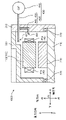
- FIG. 1A is an axial cross-sectional schematic diagram of the motor according to Embodiment 1.
- FIG. 1B is a schematic cross-sectional view of the motor in the radial direction.
- FIG. 2 is a schematic diagram of the stator viewed from the axial direction of the motor according to the first embodiment.
- FIG. 3 is a schematic diagram of the k-th turn of the coil viewed from the radial direction.
- 4A is a cross-sectional view taken along line IVA-IVA of FIG. 2.
- FIG. 4B is a cross-sectional view taken along line IVB-IVB of FIG. 2.
- FIG. FIG. 5 is a schematic cross-sectional view of a main part of another stator of the motor according to Embodiment 1.
- FIG. 6 is an axial cross-sectional schematic diagram of a motor according to a modification.
- FIG. 7 is a schematic cross-sectional view of a main part of the stator of the motor according to Embodiment 2.
- FIG. 8A is a schematic diagram of a main part of another stator of the motor according to the second embodiment, viewed from the axial direction; 8B is a perspective view of the coil shown in FIG. 8A.
- FIG. 9 is a schematic cross-sectional view of the motor according to the third embodiment in the axial direction.
- FIG. 10 is a schematic cross-sectional view of a main part of the stator of the motor according to Embodiment 3.
- FIG. 11 is an axial cross-sectional schematic diagram of another motor according to the third embodiment.
- FIG. 12 is an axial cross-sectional schematic diagram of a motor of another modification.
- FIG. 13 is an axial sectional schematic diagram of a motor of still another modification.
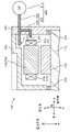
- FIG. 1A is an axial cross-sectional schematic diagram of the motor 1000 according to the first embodiment.
- FIG. 1B is a schematic cross-sectional view of the motor 1000 in the radial direction.
- the radial direction of the motor 1000 will be referred to as the "radial direction”
- the outer peripheral direction will be referred to as the "circumferential direction”
- the direction in which the axis included in the rotating shaft 210 of the motor 1000 extends are sometimes called “axial directions” respectively.
- the shaft center side of the motor 1000 may be called the inner side or the inner side, and the outer peripheral side may be called the outer side or the outer side.
- the motor 1000 is attached to equipment or equipment (not shown) such that its radial direction is parallel to the direction of gravity.
- "parallel” means parallel including the manufacturing tolerance of the motor 1000 and the mounting tolerance to equipment, etc., and it is required that the radial direction and the gravitational direction are parallel in a strict sense. not.
- the side on which the end plate 310 is provided may be referred to as the upper side, and the opposite side may be referred to as the lower side.
- the axis of the motor 1000 coincides with the axis of the rotating shaft 210 when viewed in the axial direction.
- the motor 1000 has a stator 100, a rotor 200, a motor case 300 and an end plate 310.
- a cooling device 400 is attached to the motor 1000 . Details of the structures of the stator 100 and the rotor 200 will be described later.
- the motor case 300 is a cylindrical metal member with an opening at the top.
- End plate 310 is a plate-shaped metal member provided to block the opening of motor case 300 . Note that the end plate 310 may be made of resin.
- the cooling device 400 has an oil pump 410 and a supply pipe 420 .
- the supply pipe 420 is a hollow metal member.
- the supply pipe 420 has a main pipe 430 and a branch pipe 440 .
- One end of supply pipe 420 is connected to oil pump 410 .
- Main pipe 430 extends inside motor case 300 through the radially outer side of stator 100 . Further, the main pipe 430 branches inside the end plate 310 .
- a branched pipe 440 extends inside the motor case 300 . Therefore, two ends of the supply pipe 420 are arranged inside the motor case 300 .
- a first injection port 431 is provided at the end of the main pipe 430 .
- a second injection port 441 is provided at the end of the branch pipe 440 .
- the first injection port 431 is arranged radially outside the first coil end 41a.
- the second injection port 441 is arranged axially above the first coil end 41a.
- a metal member may be used for the supply pipe 420 .
- the supply pipe 420 can be made of a resin member.
- the supply pipe 420 made of a resin member can be expected to have high insulating properties.
- the first coil end 41a is the upper end of the coil 40 in the axial direction.
- the first coil end 41a is a portion of the coil 40 that protrudes outside the slot 30, as described above.
- the second coil end 41 b is the axial lower end of the coil 40 .
- the second coil end 41 b is a portion of the coil 40 protruding outside the slot 30 .
- Supply pipe 420 may branch outside motor case 300 or may branch inside.
- oil which is a refrigerant discharged from the oil pump 410
- oil is pressure-fed into the motor case 300 through the supply pipe 420 .
- oil is jetted toward the first coil end 41a from both the first injection port 431 and the second injection port 441 to cool the first coil end 41a.
- oil is injected from the first injection port 431 toward the radial outer surface of the first coil end 41a.
- Oil is injected from the second injection port 441 toward the axial upper side surface of the first coil end 41a.
- the oil injected to the first coil end 41a is collected in an oil reservoir (not shown).
- a plurality of first injection ports 431 are provided at the end of the main pipe 430, and a plurality of second injection ports 441 are provided at the end of the branch pipe 440, respectively. Oil is injected from the first injection port 431 and the second injection port 441 toward the first coil ends 41a of the plurality of coils 40 (see FIG. 2, for example).
- Each end of main pipe 430 and branch pipe 440 located inside motor case 300 may extend a predetermined length in the circumferential direction.
- the stator 100 includes an annular yoke 20 and a plurality of teeth (tooth portions) 10 connected to the inner circumference of the yoke 20 and provided at equal intervals along the inner circumference. have.
- Yoke 20 to which teeth 10 are connected is sometimes called stator core 110 .
- the stator 100 further has slots 30 provided between teeth 10 adjacent in the circumferential direction, and coils 40 accommodated in the slots 30 .
- Stator 100 is arranged radially outwardly of rotor 200 with a constant gap therebetween.
- the teeth 10 and the yoke 20 are formed, for example, by punching electromagnetic steel sheets containing silicon or the like and laminating them.
- Coils 40 are mounted on respective teeth 10 with insulators 50 (see FIGS. 4A and 4B) interposed therebetween and housed in slots 30 .
- the coil 40 has the first coil end 41 a and the second coil end 41 b as the coil ends 41 .
- the shape of the coil 40 will be detailed later.
- the coils 40 may be referred to as coils U1-U4, V1-V4, and W1-W4, respectively, depending on the phase of the current flowing through the coils 40.
- the rotor 200 has a rotating shaft 210 , a rotor core 220 and a plurality of magnets 230 .
- Rotor core 220 has rotating shaft 210 at its center.
- a plurality of magnets 230 are embedded inside rotor core 220 , and opposite to stator 100 , N poles and S poles are alternately arranged along the outer peripheral direction of rotating shaft 210 .
- the material, shape, and material of the magnet 230 can be changed as appropriate according to the output of the motor 1000 and the like.
- the rotor core 220 is formed, for example, by punching electromagnetic steel sheets containing silicon or the like and then laminating them.
- Coils U1 to U4, coils V1 to V4, and coils W1 to W4 are connected in series. Three-phase currents of U, V, and W phases having a phase difference of 120° in electrical angle with each other are respectively supplied to coils U1 to U4, coils V1 to V4, and coils W1 to W4 to excite them, and a rotating magnetic field is generated in stator 100. occurs. This rotating magnetic field interacts with the magnetic field generated by the magnets 230 provided on the rotor 200 to generate torque, and the rotating shaft 210 is supported by the bearings 320 and rotates.
- the present disclosure can achieve similar effects even with a configuration in which the coils U1 to U4, the coils V1 to V4, and the coils W1 to W4 are connected in parallel to the stator 100, or other connection configurations. can.
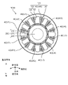
- FIG. 2 is a schematic diagram of the stator viewed from the axial direction.
- FIG. 3 is a schematic diagram of the k-th turn of the coil viewed from the radial direction.
- 4A is a cross-sectional view taken along line IVA-IVA of FIG. 2.
- FIG. 4B is a cross-sectional view taken along line IVB-IVB of FIG. 2.
- FIG. For convenience of explanation, the illustration of the yoke 20 is omitted in FIGS. 2, 4A, and 4B.
- the number of windings of the coil 40 that is, the number of turns is set to 5, it is not particularly limited to this.
- the number of turns of the coil 40 may be n (n is an integer equal to or greater than 2).
- the coil 40 is a component formed by spirally winding a conductive wire made of copper or the like.
- the coil 40 is a formed coil formed by forming the conducting wire.
- an insulating coating is formed on the surface of the conductor wire that constitutes the coil 40 .
- Formmed coil in the specification of the present application does not include a coil in which a conductive wire with a constant width and thickness is wound spirally.
- a molded coil is formed, for example, by preparing a plurality of rectangular plate materials with different lengths, widths, or thicknesses, and joining these plate materials by cold pressure welding, welding, or other methods.
- the material of the plate material is a low resistance material such as copper or aluminum.
- the molded coil may be formed by so-called casting, in which copper or the like is melted and poured into a mold.
- a formed coil may be formed by bending a plate-shaped conductive wire, which is previously formed to have different widths or thicknesses along the way, at predetermined positions.
- the formed coil may be formed by rolling a plate-shaped conductor wire with a constant width and thickness at a predetermined portion, changing the width or thickness in the middle, and then spirally winding the wire.
- the molded coil is formed by applying a process other than winding the conductive wire, or by a method different from simply winding.
- the coil 40 is a molded coil, the shape of each turn can be freely changed as described later.
- the outer shape of the k-th turn (k is an integer, 1 ⁇ k ⁇ n) of the coil 40 is a square ring having four sides when viewed from the radial direction. Two side portions facing each other and extending in the circumferential direction respectively correspond to the coil ends 41 .
- the coil end 41 located axially above is the first coil end 41a.
- the coil end 41 positioned axially lower is the second coil end 41b.
- Two axially extending side portions 42 facing each other are received within the slot 30 .
- the heights Hak and Hbk shown in FIG. 3 correspond to the heights of the k-th turns in the first coil end 41a and the second coil end 41b, respectively.
- the first turn is located on the side closer to the axis of the motor 1000 and the nth turn is located on the side closer to the yoke 20 . That is, the n-th turn is arranged radially outside the first turn.
- the arrangement order of the 12 coils 40 arranged at equal intervals along the circumferential direction is I to XII.
- Oil is injected from the first injection port 431 and the second injection port 441 of the supply pipe 420 toward the first coil ends 41a of the coil 40 arranged at positions I, II and XII, respectively.
- the position of the coil 40 where the oil is directly injected is not particularly limited to the example shown in FIG.
- oil may be injected directly into the first coil ends 41a of the coils 40 located at positions I, III and XI, respectively.
- the coils located above the positions IV and X in the gravitational direction Oil is preferably injected at 40 .
- the shapes of the first coil end 41a and the second coil end 41b differ depending on the position of the coil 40 within the stator 100.
- the height of the coil ends 41 increases from the fifth turn to the first turn.
- the height of the coil ends 41 increases from the first turn to the fifth turn.
- the coils 40 arranged at the positions IV and X may have the shape shown in FIG. 4A or the shape shown in FIG. 4B.
- the oil injected into the first coil ends 41a of the coils 40 respectively arranged at positions I, II and XII is temporarily blocked at each first turn and flows downward in the direction of gravity. is suppressed.
- the oil that has flowed downward in the direction of gravity along the first coil ends 41a is once blocked at the fifth turns of the first coil ends 41a of the coils 40 arranged at positions V to IX. Downward flow in the direction of gravity is suppressed.
- the first coil ends 41a of the coils other than the coil 40 to which the oil is directly injected are more likely to be exposed to the oil, which is the refrigerant.
- the height of the coil end 41 changes in order, but it is not particularly limited to this.
- the height Ha1 of the first turn may be higher than the heights Ha2-Ha5 of the other turns.
- the heights Ha2 to Ha5 may be the same or different.
- the height Ha5 of the fifth turn may be higher than the heights Ha1-Ha4 of the other turns.
- the heights Ha1 to Ha4 may be the same or different.
- the height Ha1 of the first turn and the height Ha2 of the second turn may be higher than the other turns.
- the height Ha5 of the fifth turn and the height Ha4 of the fourth turn may be higher than the other turns.
- the height Ha2 of the second turn may be higher than the other turns.
- the height Ha4 of the fourth turn may be higher than the other turns.
- the k-th turn (k is an integer and 1 ⁇ k ⁇ n) at the first coil end 41a where the oil is directly injected.
- the height is higher than the height of other turns, and the k-th turn should be positioned lower than at least one other turn in the direction of gravity.
- FIG. 5 is a schematic cross-sectional view of a main part of another stator of the motor according to Embodiment 1.
- FIG. 5 the height of the first coil end 41a increases from the first turn to the fifth turn.
- the heights of the k-th turn coils at the second coil end 41b are equal.
- the oil injected to the first coil end 41a is temporarily blocked at the first turn, and is prevented from flowing downward in the direction of gravity.
- the oil that has flowed downward in the direction of gravity along the first coil end 41a is temporarily blocked at the fifth turn at the first coil end 41a, and is prevented from flowing downward in the direction of gravity.
- oil does not flow through the second coil end 41b.
- the coil 40 according to this embodiment is used in the stator 100 of the motor 1000.
- FIG. The coil 40 is formed by winding a conductive wire having a square cross section and stacking n turns (n is an integer equal to or greater than 2).
- the axial direction which is the direction in which the axis of the motor 1000 extends, intersects the direction of gravity.
- the coil 40 has coil ends 41 at both ends in the axial direction.
- the height of the k-th turn (where k is an integer and 1 ⁇ k ⁇ n) is higher than the height of the other turns.
- the k-th turn is positioned below at least one other turn in the direction of gravity.
- the height of the k-th turn is set to the height of the turn located above the k-th turn in the gravitational direction. Taller than tall. By doing so, when the oil, which is the refrigerant, is injected to the first coil end 41a, the downward flow of the oil in the gravitational direction can be stopped at the k-th turn. As a result, along the first coil end 41a, it is possible to increase the amount of oil that flows from the coil 40 to which oil is directly injected to the coil 40 adjacent thereto and positioned downward in the direction of gravity. In other words, the movement of oil between the adjacent coil ends 41 is facilitated.
- each coil 40 in the stator 100 can be efficiently cooled with a small amount of oil. Since the amount of oil discharged can be reduced, the size of the oil pump 410 can be reduced. Therefore, the cost of the cooling device 400 and the cost of the motor 1000 can be reduced.
- the coil 40 is the molded coil described above, the height of a specific turn can be easily changed at the coil end 41 .
- the height of the coil end 41 increases downward in the direction of gravity.
- the height of the first turn of the coil end 41 or the height of the nth turn is preferably higher than the height of the other turns.
- each coil 40 in the stator 100 can be efficiently cooled with a small amount of oil. Also, the size of the oil pump 410 can be reduced. Therefore, the cost of the cooling device 400 and the cost of the motor 1000 can be reduced.
- a motor 1000 includes a rotor 200 having a rotation shaft 210 including an axial center, a stator 100 provided coaxially with the rotor 200 and spaced from the rotor 200 by a predetermined distance, and the stator 100 and the rotor 200. and a motor case 300 that accommodates the inside.
- the stator 100 has a stator core 110 having a plurality of teeth (tooth portions) 10 and coils 40 attached to each of the plurality of teeth 10 .
- the motor 1000 further includes a cooling device 400 that supplies oil, which is a coolant, toward at least one coil 40 .
- the cooling device 400 includes an oil pump (pump) 410 that discharges oil, and is connected to the oil pump 410 and extends inside the motor case 300 . It has a feed tube 420 feeding towards.
- pump oil pump
- the oil supplied from the cooling device 400 can be injected to the coil 40 to reliably cool the coil 40 which is the main heat source in the motor 1000 .
- thermal loss generated in the coil 40 can be suppressed. Therefore, the efficiency of motor 1000 can be improved.
- the coil 40 can be efficiently cooled.
- the oil, which is the coolant is injected to the first coil end 41a, it is possible to temporarily stop the downward flow of the oil in the direction of gravity. Therefore, along the axial upper side surface of the first coil end 41a, the oil can efficiently flow downward in the direction of gravity. In other words, the movement of oil between the adjacent coil ends 41 is facilitated.
- each coil 40 in the stator 100 can be efficiently cooled with a small amount of oil. Therefore, the efficiency of motor 1000 can be improved.
- the size of the oil pump 410 can be reduced. Therefore, the cost of the cooling device 400 and the cost of the motor 1000 can be reduced.
- the supply pipe 420 has a first injection port 431 that injects oil from above in the direction of gravity.
- the coil end 41 includes a first coil end 41a as an axially upper end and a second coil end 41b as a lower end.
- the first injection port 431 is preferably arranged above the first coil end 41a when viewed in the direction of gravity.
- the supply pipe 420 preferably further has a second injection port 441 for injecting oil in the axial direction.
- the oil that is injected from the second injection port 441 and sprayed onto the axially upper side surface of the first coil end 41a is also temporarily dammed by the first coil end 41a, and flows along the axially upper side surface of the first coil end 41a.
- the water tends to flow downward in the direction of gravity.
- each coil 40 in the stator 100 can be efficiently cooled with a small amount of oil. Therefore, the efficiency of motor 1000 can be improved.
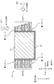
- FIG. 6 is an axial cross-sectional schematic diagram of a motor 1000 according to a modification.
- the same reference numerals are given to the same parts as in the first embodiment, and detailed description thereof will be omitted.
- the motor 1000 of this modified example shown in FIG. 6 differs from the motor 1000 of Embodiment 1 shown in FIG. 1A in the shape of the supply pipe 420 .
- the main pipe 430 passes between the stator 100 and the motor case 300 and extends radially outward of the second coil end 41b.
- One of the pair of first injection ports 431 is located in the intermediate portion of the main pipe 430 and radially outward of the first coil end 41a.
- the other one 432 of the pair of first injection ports is arranged in the intermediate portion of the main pipe 430 and radially outside the second coil end 41b. Therefore, the oil injected from the pair of first injection ports 431 and 432 is sprayed onto the radial outer surfaces of the first coil end 41a and the second coil end 41b.
- another branch pipe 450 extends from the end of the main pipe 430 toward the axis of the motor 1000.
- a pair of second injection ports 441, 451 are provided at the end of the branch pipe 450.
- a second injection port 451 is provided facing the axial lower surface of the second coil end 41b. Therefore, the oil injected from the second injection port 441 facing the first coil end 41a out of the pair of second injection ports 441, 451 is sprayed onto the axial upper side surface of the first coil end 41a, and the second coil The oil injected from the second injection port 451 facing the end 41b is sprayed onto the axial lower surface of the second coil end 41b.
- the oil which is the refrigerant
- the oil can be injected not only to the first coil end 41a but also to the second coil end 41b.
- the oil can efficiently flow downward in the direction of gravity along the axial upper side surface of the first coil end 41a and the axial lower side surface of the second coil end 41b. Therefore, the heat exchange efficiency between the coil 40 and oil is further improved as compared with the configuration shown in the first embodiment.
- each coil 40 in the stator 100 can be efficiently cooled with a small amount of oil.
- the size of the oil pump 410 can be reduced. Therefore, the cost of the cooling device 400 and the cost of the motor 1000 can be reduced.
- the arrangement space of the supply pipe 420 within the motor case 300 can be reduced.
- the volume of the motor 1000 can be reduced by the portion surrounded by the dashed line shown in FIG. 1A, and the motor 1000 can be miniaturized.
- FIG. 7 is a schematic cross-sectional view of a main part of stator 100 of motor 1000 according to the second embodiment. All the coils 40 attached to the stator 100, that is, the coils 40 arranged at positions I to XII shown in FIG. 2 have the shape shown in FIG.
- the heights Ha1 and Ha5 of the first and fifth turns in the first coil end 41a are higher than the heights Ha2 to Ha4 of the second to fourth turns. It differs from the coil 40 shown in the first embodiment. In that the heights Hb1 and Hb5 of the first and fifth turns in the second coil end 41b are higher than the heights Hb2 to Hb4 of the second to fourth turns, the coil 40 shown in the first embodiment is different. different.
- the space sandwiched between the first turn and the fifth turn functions as an oil flow path.
- the oil injected to the first coil end 41a smoothly flows downward in the direction of gravity along the axial upper side surface of the first coil end 41a.
- each coil 40 in the stator 100 can be efficiently cooled with a small amount of oil. Therefore, the efficiency of motor 1000 can be improved. Since the amount of oil discharged can be reduced, the size of the oil pump 410 can be reduced. Therefore, the cost of the cooling device 400 and the cost of the motor 1000 can be reduced.
- an oil introduction notch 43 which will be described later in detail with reference to FIGS. 8A and 8B, is formed. It is preferable to provide
- FIG. 8A is a schematic diagram of a main part of another stator 100 of the motor 1000 according to Embodiment 2, viewed from the axial direction.
- FIG. 8B is a perspective view of the coil 40 of FIG. 8A.
- the coils 40 shown in FIGS. 8A and 8B are arranged inside the stator 100 at positions where oil is directly injected, for example, positions I, II and XII shown in FIG.
- the coil 40 shown in FIGS. 8A and 8B has a notch 43 in the fifth turn of the first coil end 41a.
- the oil injected from the first injection port 431 is surely introduced into the space sandwiched between the first turn and the fifth turn through the notch 43 .
- the oil injected to the first coil end 41a smoothly flows downward in the direction of gravity along the axial upper side surface of the first coil end 41a.
- each coil 40 in the stator 100 can be efficiently cooled with a small amount of oil. Therefore, the efficiency of motor 1000 can be improved. Since the amount of oil discharged can be reduced, the size of the oil pump 410 can be reduced. Therefore, the cost of the cooling device 400 and the cost of the motor 1000 can be reduced.
- the height Ha2 of the second turn may be the same as the heights Ha1 and Ha5 of the first and fifth turns.
- the height Ha4 of the fourth turn may be the same as the heights Ha1 and Ha5 of the first and fifth turns.
- the heights Ha2 and Ha4 of the second and fourth turns may be the same as the heights Ha1 and Ha5 of the first and fifth turns.
- the height of each turn should be set so that a concave portion is formed when viewed from above in the axial direction.
- the height of each turn may be set so that a concave portion is formed when viewed from below in the axial direction.
- the notch 43 mentioned above does not need to be provided only in the fifth turn.
- the notch 43 may be provided in the turn positioned higher in the gravitational direction than the other turns among the turns higher than the other turns.
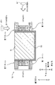
- FIG. 9 is an axial cross-sectional schematic diagram of the motor 1000 according to the third embodiment.
- FIG. 10 is a schematic cross-sectional view of a main part of stator 100 of motor 1000 according to the third embodiment.
- FIG. 11 is an axial cross-sectional schematic diagram of another motor according to the third embodiment.
- a motor 1000 shown in FIG. 9 has the same configuration as the motor 1000 shown in the first embodiment.
- the surface area of the second coil end 41b which is not sprayed with oil as a coolant, is made larger than the surface area of the first coil end 41a, which is sprayed with oil.
- the volume of the second coil end 41b may be larger than the volume of the first coil end 41a.
- the heat dissipation area of the second coil end 41b can be made larger than that of the first coil end 41a, and the amount of heat dissipation in the second coil end 41b can be increased.
- the oil is injected to the first coil end 41a, which has a small heat radiation area and tends to trap heat, heat exchange with the oil can increase the amount of heat radiation from the first coil end 41a.
- the heat generated in the coil 40 can be reliably dissipated without injecting oil to the second coil end 41b. Therefore, the efficiency of motor 1000 can be improved. Since the amount of oil discharged can be reduced, the size of the oil pump 410 can be reduced. Therefore, the cost of the cooling device 400 and the cost of the motor 1000 can be reduced.
- the space for arranging the supply pipe 420 in the motor case 300 can be reduced, as in the modified example. 6, the volume of the motor 1000 can be reduced by the portion surrounded by the broken line shown in FIG. 9, and the size of the motor 1000 can be reduced. Moreover, since the volume of the first coil end 41a can be made smaller than the volume of the second coil end 41b, the axial size of the motor 1000 can be reduced. Therefore, the motor 1000 can be miniaturized.
- the surface area of the second coil end 41b is appropriately set according to the amount of heat radiation required from the second coil end 41b.
- the shapes of the first coil end 41a and the second coil end 41b can be appropriately changed within a range in which the surface area of the first coil end 41a is smaller than the surface area of the second coil end 41b.
- the height Hbk of the k-th turn of the second coil end 41b is equal to the height of the k-th turn of the first coil end 41a. It may be higher than Hak.
- the height Hbk of the kth turn of the second coil end 41b may be the same as the height Ha1 of the first turn of the first coil end 41a.
- all turns may have the same height in the first coil end 41a.
- all turns may have the same height in the second coil end 41b.
- the height Hbk of the k-th turn of the second coil end 41b must be higher than the height Hak of the k-th turn of the first coil end 41a.
- the surface area of the first coil end 41a to which the oil as the coolant is sprayed may be made larger than the surface area of the second coil end 41b to which the oil is not sprayed.
- the volume of the first coil end 41a may be larger than the volume of the second coil end 41b.
- the amount of heat radiation from the coil 40 can be reliably increased by injecting oil directly to the coil end 41 rather than radiating heat from the coil end 41 to the outside atmosphere. Therefore, as shown in FIG. 11, the coil 40 may be actively cooled by injecting oil to the first coil end 41a having a larger surface area than the second coil end 41b.
- the heat generated by the coil 40 can be reliably dissipated without injecting oil to the second coil end 41b, and the efficiency of the motor 1000 can be improved. Since the amount of oil discharged can be reduced, the size of the oil pump 410 can be reduced. Therefore, the cost of the cooling device 400 and the cost of the motor 1000 can be reduced. Furthermore, the space for arranging the supply pipe 420 within the motor case 300 can be reduced. Therefore, the motor 1000 can be miniaturized.
- the shapes of the first coil end 41a and the second coil end 41b can be appropriately changed within a range where the surface area of the second coil end 41b is smaller than the surface area of the first coil end 41a.
- the relationship between the height of k turns in the first coil end 41a and the height of k turns in the second coil end 41b is opposite to that described above.
- the height Hak of the k-th turn of the first coil end 41a is the height of the k-th turn of the second coil end 41b. higher than Hbk.
- the height Hak of the k-th turn of the first coil end 41a is higher than the height Hbk of the k-th turn of the second coil end 41b.
- a new embodiment can be obtained by appropriately combining the constituent elements shown in Embodiments 1 to 3 and modifications.
- the coil 40 shown in FIGS. 7, 8A, and 8B may be used in the modified motor 1000 shown in FIG. In that case, it goes without saying that the notch 43 is preferably provided also in the fifth turn of the second coil end 41b.
- the 3-phase 12-slot motor 1000 has been described as an example. However, it is not particularly limited to this. Other structures, for example, a 3-phase 6-slot motor 1000 may be used.
- the structure of the supply pipe 420 is also not particularly limited to the examples shown in FIGS. 1A and 6.
- the branch pipes 440, 450 or the second injection ports 441, 451 may be omitted.
- the structure of the motor 1000 of the present disclosure is not limited to the examples shown in the first to third embodiments and modifications.
- the structure of the motor 1000 of the present disclosure may take still another structure.
- FIG. 12 is an axial cross-sectional schematic diagram of a motor 1000 of another modified example.
- FIG. 13 is a schematic axial cross-sectional view of a motor 1000 of still another modification.
- the supply pipe 420 has been described as having the main pipe 430 and the branch pipe 440 . Only one supply pipe 420 may be formed. For example, as shown in FIG. 12, the supply pipe 420 may be shaped using only the main pipe 430 shown in FIG. 1A. Alternatively, the supply pipe may be shaped using only the branch pipe 440 .
- the cooling device 400 may change the direction in which the motor 1000 is attached according to the direction in which the motor 1000 is attached to the installation object.
- the motor 1000 may be installed so that the direction of gravity and the axial direction are the same.
- the oil pump 410 may be installed on the outer peripheral side in the radial direction.
- the supply pipe 420 extends inside the motor case 300 through the inside of the end plate 310, like the branch pipe 440 shown in FIG. 1A.
- the coil of the present disclosure facilitates the movement of coolant between adjacent coil ends and enhances the cooling efficiency of the coolant. Accordingly, the coils of the present disclosure are useful in motors.
Abstract
Description
[モータの構成]
図1Aは、実施形態1に係るモータ1000の軸方向の断面模式図である。図1Bは、モータ1000の径方向の断面模式図である。なお、以降の説明において、モータ1000の半径方向を「径方向」と、外周方向を「周方向」と、モータ1000の回転軸210に含まれる軸心が延伸する方向(図1Bにおける紙面と垂直な方向)を「軸方向」とそれぞれ呼ぶことがある。径方向において、モータ1000の軸心側を内または内側と、外周側を外または外側と呼ぶことがある。図1Aに示すように、モータ1000は、径方向が重力方向と平行となるように、図示しない設備または機器に取り付けられている。なお、この場合の「平行」とは、モータ1000の製造公差及び機器等への取り付け公差を含んで平行という意味であり、径方向と重力方向とが厳密な意味で平行であることまでは要求されない。 (Embodiment 1)
[Motor configuration]
FIG. 1A is an axial cross-sectional schematic diagram of the
図2は、軸方向から見たステータの模式図である。図3は、コイルの第kターンを径方向から見た模式図である。図4Aは、図2のIVA-IVA線での断面図である。図4Bは、図2のIVB-IVB線での断面図である。なお、説明の便宜上、図2及び図4A,図4Bにおいて、ヨーク20の図示を省略している。また、コイル40の巻回数、つまり、ターン数を5としているが特にこれに限定されない。コイル40のターン数はn(nは2以上の整数)であればよい。 [Main part of stator and configuration of coil]
FIG. 2 is a schematic diagram of the stator viewed from the axial direction. FIG. 3 is a schematic diagram of the k-th turn of the coil viewed from the radial direction. 4A is a cross-sectional view taken along line IVA-IVA of FIG. 2. FIG. 4B is a cross-sectional view taken along line IVB-IVB of FIG. 2. FIG. For convenience of explanation, the illustration of the
以上説明したように、本実施形態に係るコイル40は、モータ1000のステータ100に用いられる。コイル40は、断面が四角形の導線が巻回され、nターン(nは2以上の整数)積層されてなる。モータ1000の軸心が延伸する方向である軸方向は、重力方向と交差している。 [Effects, etc.]
As described above, the
図6は、変形例に係るモータ1000の軸方向の断面模式図である。なお、説明の便宜上、図6及び以降に示す各図面において、実施形態1と同様の箇所については同一の符号を付して詳細な説明を省略する。 <Modification>
FIG. 6 is an axial cross-sectional schematic diagram of a
図7は、実施形態2に係るモータ1000のステータ100の要部の断面模式図である。なお、ステータ100に装着されるすべてのコイル40、つまり、図2に示す位置I~XIIのそれぞれに配置されるコイル40は、図7に示す形状となっている。 (Embodiment 2)
FIG. 7 is a schematic cross-sectional view of a main part of
図9は、実施形態3に係るモータ1000の軸方向の断面模式図である。図10は、実施形態3に係るモータ1000のステータ100の要部の断面模式図である。図11は、実施形態3に係る別のモータの軸方向の断面模式図である。 (Embodiment 3)
FIG. 9 is an axial cross-sectional schematic diagram of the
実施形態1~3及び変形例に示す構成要素を適宜組み合わせて、新たな実施形態とすることもできる。例えば、図6に示す変形例のモータ1000に、図7,図8A及び図8Bに示すコイル40が用いられてもよい。その場合、第2コイルエンド41bにおける第5ターンにも切り欠き43が設けられるのが好ましいことは言うまでもない。 (Other embodiments)
A new embodiment can be obtained by appropriately combining the constituent elements shown in Embodiments 1 to 3 and modifications. For example, the
20 ヨーク
30 スロット
40 コイル
41 コイルエンド
41a 第1コイルエンド
41b 第2コイルエンド
42 辺部
43 切り欠き
50 インシュレータ
100 ステータ
110 ステータコア
200 ロータ
210 回転軸
220 ロータコア
230 磁石
300 モータケース
310 エンドプレート
320 軸受
400 冷却装置
410 オイルポンプ(ポンプ)
420 供給管
430 主管
431,432 第1噴射口
440,450 枝管
441,451 第2噴射口
1000 モータ 10 teeth
20
420
Claims (12)
- モータのステータに用いられるコイルであって、
前記モータの軸心が延伸する方向である軸方向が重力方向と交差して用いられるとき、
前記コイルは、断面が四角形の導線が巻回され、nターン(nは2以上の整数)積層されてなり、
前記コイルは、前記軸方向の両端部のそれぞれにコイルエンドを有しており、
一方の前記コイルエンドにおいて、第kターン(kは整数で、1≦k≦n)の高さが、他のターンの高さよりも高く、
前記第kターンは、他の1つのターンよりも前記重力方向で下側に位置しているコイル。 A coil used in a motor stator,
When the axial direction, which is the direction in which the axis of the motor extends, intersects the direction of gravity,
The coil is formed by winding a conductive wire having a square cross section and stacking n turns (n is an integer of 2 or more),
The coil has coil ends at both ends in the axial direction,
In one of the coil ends, the height of the k-th turn (where k is an integer and 1≤k≤n) is higher than the height of the other turns,
A coil in which the k-th turn is positioned lower than the other one turn in the gravitational direction. - 請求項1に記載のコイルにおいて、
前記重力方向で下側に向かうにつれて、前記コイルエンドの高さが高くなっているコイル。 In the coil of claim 1,
A coil in which the height of the coil end increases toward the lower side in the gravitational direction. - 請求項1または2に記載のコイルにおいて、
前記コイルエンドの第1ターンの高さ、または第nターンの高さが、他のターンの高さよりも高いコイル。 In the coil according to claim 1 or 2,
A coil in which the height of the first turn or the height of the n-th turn of the coil end is higher than the height of the other turns. - 請求項1に記載のコイルにおいて、
前記コイルエンドの第1及び第nターンの高さが、他のターンの高さよりも高いコイル。 In the coil of claim 1,
A coil in which heights of the first and nth turns of the coil end are higher than heights of other turns. - 請求項4に記載のコイルにおいて、
前記他のターンよりも前記コイルエンドの高さが高いターンのうち、前記他のターンよりも前記重力方向で上側に位置するターンには、切り欠きが設けられているコイル。 In the coil according to claim 4,
A coil in which a notch is provided in a turn positioned above the other turn in the gravitational direction among the turns whose coil ends are higher than the other turns. - 前記軸方向に延伸する回転軸を有するロータと、
前記ロータと同軸にかつ前記ロータと所定の間隔をあけて設けられた前記ステータと、
前記ステータと前記ロータとを内部に収容するモータケースと、を備え、
前記ステータは、
複数の歯部を有するステータコアと、
前記複数の歯部のそれぞれに装着された請求項1~5のいずれか1項に記載のコイルと、を有するモータ。 a rotor having a rotating shaft extending in the axial direction;
the stator provided coaxially with the rotor and spaced from the rotor by a predetermined distance;
a motor case that accommodates the stator and the rotor inside,
The stator is
a stator core having a plurality of teeth;
and a coil according to any one of claims 1 to 5 attached to each of the plurality of teeth. - 請求項6に記載のモータにおいて、
前記コイルに向けて冷媒を供給する冷却装置をさらに備え、
前記冷却装置は、
前記冷媒を吐出するポンプと、
前記ポンプに接続されて前記モータケースの内部に延び、前記ポンプから吐出された前記冷媒を前記コイルに向けて供給する供給管を、を有するモータ。 A motor according to claim 6, wherein
Further comprising a cooling device that supplies a coolant toward the coil,
The cooling device
a pump for discharging the refrigerant;
a supply pipe connected to the pump, extending inside the motor case, and supplying the refrigerant discharged from the pump toward the coil. - 請求項7に記載のモータにおいて、
前記供給管は、前記冷媒を前記重力方向で上側から噴射する第1噴射口を有するモータ。 A motor according to claim 7, wherein
The motor, wherein the supply pipe has a first injection port for injecting the coolant from above in the direction of gravity. - 請求項8に記載のモータにおいて、
前記供給管は、前記冷媒を前記軸方向に噴射する第2噴射口をさらに有するモータ。 A motor according to claim 8, wherein
The motor, wherein the supply pipe further includes a second injection port for injecting the coolant in the axial direction. - 請求項8または9に記載のモータにおいて、
前記コイルエンドは、前記軸方向の一方の端部である第1コイルエンドと、前記軸方向の他方の端部である第2コイルエンドとを含み、
前記重力方向で見て、前記第1噴射口は、少なくとも前記第1コイルエンドの上方に配置されているモータ。 The motor according to claim 8 or 9,
The coil end includes a first coil end that is one end in the axial direction and a second coil end that is the other end in the axial direction,
The motor, wherein the first injection port is arranged at least above the first coil end when viewed in the gravitational direction. - 請求項10に記載のモータにおいて、
前記第2コイルエンドの表面積は、前記第1コイルエンドの表面積よりも大きいモータ。 11. The motor of claim 10, wherein
The motor, wherein the surface area of the second coil end is larger than the surface area of the first coil end. - 請求項10に記載のモータにおいて、
前記第1コイルエンドの表面積は、前記第2コイルエンドの表面積よりも大きいモータ。 11. The motor of claim 10, wherein
The motor, wherein the surface area of the first coil end is larger than the surface area of the second coil end.
Priority Applications (4)
| Application Number | Priority Date | Filing Date | Title |
|---|---|---|---|
| CN202280017657.1A CN116941163A (en) | 2021-03-02 | 2022-02-04 | Coil and motor provided with same |
| US18/547,521 US20240055922A1 (en) | 2021-03-02 | 2022-02-04 | Coil and motor provided with same |
| JP2023503655A JPWO2022185842A1 (en) | 2021-03-02 | 2022-02-04 | |
| EP22762899.7A EP4304057A1 (en) | 2021-03-02 | 2022-02-04 | Coil and motor provided with same |
Applications Claiming Priority (2)
| Application Number | Priority Date | Filing Date | Title |
|---|---|---|---|
| JP2021-032942 | 2021-03-02 | ||
| JP2021032942 | 2021-03-02 |
Publications (1)
| Publication Number | Publication Date |
|---|---|
| WO2022185842A1 true WO2022185842A1 (en) | 2022-09-09 |
Family
ID=83155026
Family Applications (1)
| Application Number | Title | Priority Date | Filing Date |
|---|---|---|---|
| PCT/JP2022/004537 WO2022185842A1 (en) | 2021-03-02 | 2022-02-04 | Coil and motor provided with same |
Country Status (5)
| Country | Link |
|---|---|
| US (1) | US20240055922A1 (en) |
| EP (1) | EP4304057A1 (en) |
| JP (1) | JPWO2022185842A1 (en) |
| CN (1) | CN116941163A (en) |
| WO (1) | WO2022185842A1 (en) |
Citations (5)
| Publication number | Priority date | Publication date | Assignee | Title |
|---|---|---|---|---|
| JPH08130856A (en) | 1994-10-31 | 1996-05-21 | Aisin Aw Co Ltd | Cooling circuit for motor |
| JP2013158177A (en) * | 2012-01-31 | 2013-08-15 | Toyota Motor Corp | Stator of rotary electric machine |
| DE102012212637A1 (en) | 2012-07-18 | 2014-01-23 | Fraunhofer-Gesellschaft zur Förderung der angewandten Forschung e.V. | Casting electrical coil |
| WO2020017143A1 (en) * | 2018-07-18 | 2020-01-23 | パナソニックIpマネジメント株式会社 | Motor |
| WO2020105467A1 (en) * | 2018-11-20 | 2020-05-28 | ジヤトコ株式会社 | Motor oil cooling structure |
-
2022
- 2022-02-04 JP JP2023503655A patent/JPWO2022185842A1/ja active Pending
- 2022-02-04 US US18/547,521 patent/US20240055922A1/en active Pending
- 2022-02-04 WO PCT/JP2022/004537 patent/WO2022185842A1/en active Application Filing
- 2022-02-04 EP EP22762899.7A patent/EP4304057A1/en active Pending
- 2022-02-04 CN CN202280017657.1A patent/CN116941163A/en active Pending
Patent Citations (5)
| Publication number | Priority date | Publication date | Assignee | Title |
|---|---|---|---|---|
| JPH08130856A (en) | 1994-10-31 | 1996-05-21 | Aisin Aw Co Ltd | Cooling circuit for motor |
| JP2013158177A (en) * | 2012-01-31 | 2013-08-15 | Toyota Motor Corp | Stator of rotary electric machine |
| DE102012212637A1 (en) | 2012-07-18 | 2014-01-23 | Fraunhofer-Gesellschaft zur Förderung der angewandten Forschung e.V. | Casting electrical coil |
| WO2020017143A1 (en) * | 2018-07-18 | 2020-01-23 | パナソニックIpマネジメント株式会社 | Motor |
| WO2020105467A1 (en) * | 2018-11-20 | 2020-05-28 | ジヤトコ株式会社 | Motor oil cooling structure |
Also Published As
| Publication number | Publication date |
|---|---|
| US20240055922A1 (en) | 2024-02-15 |
| JPWO2022185842A1 (en) | 2022-09-09 |
| EP4304057A1 (en) | 2024-01-10 |
| CN116941163A (en) | 2023-10-24 |
Similar Documents
| Publication | Publication Date | Title |
|---|---|---|
| US9553496B2 (en) | Low-inertia direct drive having high power density | |
| US7649299B2 (en) | Rotating electrical machine and alternating-current generator | |
| US20220166275A1 (en) | High performance electromagnetic machine and cooling system | |
| EP3588743B1 (en) | Motor | |
| US20150270754A1 (en) | Dual-rotor electric rotating machine | |
| US11165310B2 (en) | Stator for a rotating electric machine having dielectric regions for a winding head board | |
| CN103229393A (en) | Permanent magnet rotor for electric machine | |
| JP4665454B2 (en) | motor | |
| JP2019161752A (en) | Rotary electric machine stator | |
| EP3588744B1 (en) | Motor | |
| CN110313113B (en) | Motor | |
| JP2016208757A (en) | Rotary electric machine for vehicle | |
| JP7122505B2 (en) | Coil and motor using it | |
| WO2022185842A1 (en) | Coil and motor provided with same | |
| CN114846728A (en) | Coil, stator provided with same, and motor | |
| WO2022185841A1 (en) | Stator and motor equipped with same | |
| US11289979B2 (en) | Rotary electric machine | |
| EP4040648A1 (en) | Stator of electric machine | |
| JPWO2022185841A5 (en) | ||
| JP2012005204A (en) | Motor cooling structure | |
| JP2016129447A (en) | Rotary electric machine | |
| JPWO2022185842A5 (en) | ||
| WO2023106338A1 (en) | Motor | |
| CN116134703A (en) | Cooled rotor for an electric machine |
Legal Events
| Date | Code | Title | Description |
|---|---|---|---|
| 121 | Ep: the epo has been informed by wipo that ep was designated in this application |
Ref document number: 22762899 Country of ref document: EP Kind code of ref document: A1 |
|
| ENP | Entry into the national phase |
Ref document number: 2023503655 Country of ref document: JP Kind code of ref document: A |
|
| WWE | Wipo information: entry into national phase |
Ref document number: 18547521 Country of ref document: US |
|
| WWE | Wipo information: entry into national phase |
Ref document number: 202280017657.1 Country of ref document: CN |
|
| WWE | Wipo information: entry into national phase |
Ref document number: 2022762899 Country of ref document: EP |
|
| NENP | Non-entry into the national phase |
Ref country code: DE |
|
| ENP | Entry into the national phase |
Ref document number: 2022762899 Country of ref document: EP Effective date: 20231002 |