WO2020012876A1 - 流体取扱装置および流体取扱システム - Google Patents
流体取扱装置および流体取扱システム Download PDFInfo
- Publication number
- WO2020012876A1 WO2020012876A1 PCT/JP2019/023852 JP2019023852W WO2020012876A1 WO 2020012876 A1 WO2020012876 A1 WO 2020012876A1 JP 2019023852 W JP2019023852 W JP 2019023852W WO 2020012876 A1 WO2020012876 A1 WO 2020012876A1
- Authority
- WO
- WIPO (PCT)
- Prior art keywords
- rotary member
- valve
- flow path
- channel
- fluid
- Prior art date
- Legal status (The legal status is an assumption and is not a legal conclusion. Google has not performed a legal analysis and makes no representation as to the accuracy of the status listed.)
- Ceased
Links
Images






Classifications
-
- F—MECHANICAL ENGINEERING; LIGHTING; HEATING; WEAPONS; BLASTING
- F16—ENGINEERING ELEMENTS AND UNITS; GENERAL MEASURES FOR PRODUCING AND MAINTAINING EFFECTIVE FUNCTIONING OF MACHINES OR INSTALLATIONS; THERMAL INSULATION IN GENERAL
- F16K—VALVES; TAPS; COCKS; ACTUATING-FLOATS; DEVICES FOR VENTING OR AERATING
- F16K99/00—Subject matter not provided for in other groups of this subclass
- F16K99/0001—Microvalves
- F16K99/0003—Constructional types of microvalves; Details of the cutting-off member
- F16K99/0028—Valves having multiple inlets or outlets
-
- B—PERFORMING OPERATIONS; TRANSPORTING
- B01—PHYSICAL OR CHEMICAL PROCESSES OR APPARATUS IN GENERAL
- B01L—CHEMICAL OR PHYSICAL LABORATORY APPARATUS FOR GENERAL USE
- B01L3/00—Containers or dishes for laboratory use, e.g. laboratory glassware; Droppers
- B01L3/50—Containers for the purpose of retaining a material to be analysed, e.g. test tubes
- B01L3/502—Containers for the purpose of retaining a material to be analysed, e.g. test tubes with fluid transport, e.g. in multi-compartment structures
- B01L3/5027—Containers for the purpose of retaining a material to be analysed, e.g. test tubes with fluid transport, e.g. in multi-compartment structures by integrated microfluidic structures, i.e. dimensions of channels and chambers are such that surface tension forces are important, e.g. lab-on-a-chip
- B01L3/502746—Containers for the purpose of retaining a material to be analysed, e.g. test tubes with fluid transport, e.g. in multi-compartment structures by integrated microfluidic structures, i.e. dimensions of channels and chambers are such that surface tension forces are important, e.g. lab-on-a-chip characterised by the means for controlling flow resistance, e.g. flow controllers, baffles or throttle valves
-
- B—PERFORMING OPERATIONS; TRANSPORTING
- B01—PHYSICAL OR CHEMICAL PROCESSES OR APPARATUS IN GENERAL
- B01J—CHEMICAL OR PHYSICAL PROCESSES, e.g. CATALYSIS OR COLLOID CHEMISTRY; THEIR RELEVANT APPARATUS
- B01J19/00—Chemical, physical or physico-chemical processes in general; Their relevant apparatus
-
- B—PERFORMING OPERATIONS; TRANSPORTING
- B01—PHYSICAL OR CHEMICAL PROCESSES OR APPARATUS IN GENERAL
- B01L—CHEMICAL OR PHYSICAL LABORATORY APPARATUS FOR GENERAL USE
- B01L3/00—Containers or dishes for laboratory use, e.g. laboratory glassware; Droppers
- B01L3/50—Containers for the purpose of retaining a material to be analysed, e.g. test tubes
- B01L3/502—Containers for the purpose of retaining a material to be analysed, e.g. test tubes with fluid transport, e.g. in multi-compartment structures
- B01L3/5027—Containers for the purpose of retaining a material to be analysed, e.g. test tubes with fluid transport, e.g. in multi-compartment structures by integrated microfluidic structures, i.e. dimensions of channels and chambers are such that surface tension forces are important, e.g. lab-on-a-chip
- B01L3/502738—Containers for the purpose of retaining a material to be analysed, e.g. test tubes with fluid transport, e.g. in multi-compartment structures by integrated microfluidic structures, i.e. dimensions of channels and chambers are such that surface tension forces are important, e.g. lab-on-a-chip characterised by integrated valves
-
- B—PERFORMING OPERATIONS; TRANSPORTING
- B01—PHYSICAL OR CHEMICAL PROCESSES OR APPARATUS IN GENERAL
- B01L—CHEMICAL OR PHYSICAL LABORATORY APPARATUS FOR GENERAL USE
- B01L3/00—Containers or dishes for laboratory use, e.g. laboratory glassware; Droppers
- B01L3/56—Labware specially adapted for transferring fluids
- B01L3/567—Valves, taps or stop-cocks
-
- F—MECHANICAL ENGINEERING; LIGHTING; HEATING; WEAPONS; BLASTING
- F16—ENGINEERING ELEMENTS AND UNITS; GENERAL MEASURES FOR PRODUCING AND MAINTAINING EFFECTIVE FUNCTIONING OF MACHINES OR INSTALLATIONS; THERMAL INSULATION IN GENERAL
- F16K—VALVES; TAPS; COCKS; ACTUATING-FLOATS; DEVICES FOR VENTING OR AERATING
- F16K11/00—Multiple-way valves, e.g. mixing valves; Pipe fittings incorporating such valves
- F16K11/10—Multiple-way valves, e.g. mixing valves; Pipe fittings incorporating such valves with two or more closure members not moving as a unit
- F16K11/20—Multiple-way valves, e.g. mixing valves; Pipe fittings incorporating such valves with two or more closure members not moving as a unit operated by separate actuating members
- F16K11/202—Multiple-way valves, e.g. mixing valves; Pipe fittings incorporating such valves with two or more closure members not moving as a unit operated by separate actuating members with concentric handles
-
- F—MECHANICAL ENGINEERING; LIGHTING; HEATING; WEAPONS; BLASTING
- F16—ENGINEERING ELEMENTS AND UNITS; GENERAL MEASURES FOR PRODUCING AND MAINTAINING EFFECTIVE FUNCTIONING OF MACHINES OR INSTALLATIONS; THERMAL INSULATION IN GENERAL
- F16K—VALVES; TAPS; COCKS; ACTUATING-FLOATS; DEVICES FOR VENTING OR AERATING
- F16K11/00—Multiple-way valves, e.g. mixing valves; Pipe fittings incorporating such valves
- F16K11/10—Multiple-way valves, e.g. mixing valves; Pipe fittings incorporating such valves with two or more closure members not moving as a unit
- F16K11/20—Multiple-way valves, e.g. mixing valves; Pipe fittings incorporating such valves with two or more closure members not moving as a unit operated by separate actuating members
- F16K11/22—Multiple-way valves, e.g. mixing valves; Pipe fittings incorporating such valves with two or more closure members not moving as a unit operated by separate actuating members with an actuating member for each valve, e.g. interconnected to form multiple-way valves
-
- F—MECHANICAL ENGINEERING; LIGHTING; HEATING; WEAPONS; BLASTING
- F16—ENGINEERING ELEMENTS AND UNITS; GENERAL MEASURES FOR PRODUCING AND MAINTAINING EFFECTIVE FUNCTIONING OF MACHINES OR INSTALLATIONS; THERMAL INSULATION IN GENERAL
- F16K—VALVES; TAPS; COCKS; ACTUATING-FLOATS; DEVICES FOR VENTING OR AERATING
- F16K99/00—Subject matter not provided for in other groups of this subclass
- F16K99/0001—Microvalves
- F16K99/0003—Constructional types of microvalves; Details of the cutting-off member
- F16K99/0015—Diaphragm or membrane valves
-
- G—PHYSICS
- G01—MEASURING; TESTING
- G01N—INVESTIGATING OR ANALYSING MATERIALS BY DETERMINING THEIR CHEMICAL OR PHYSICAL PROPERTIES
- G01N37/00—Details not covered by any other group of this subclass
-
- B—PERFORMING OPERATIONS; TRANSPORTING
- B01—PHYSICAL OR CHEMICAL PROCESSES OR APPARATUS IN GENERAL
- B01L—CHEMICAL OR PHYSICAL LABORATORY APPARATUS FOR GENERAL USE
- B01L2300/00—Additional constructional details
- B01L2300/08—Geometry, shape and general structure
- B01L2300/0809—Geometry, shape and general structure rectangular shaped
- B01L2300/0816—Cards, e.g. flat sample carriers usually with flow in two horizontal directions
-
- B—PERFORMING OPERATIONS; TRANSPORTING
- B01—PHYSICAL OR CHEMICAL PROCESSES OR APPARATUS IN GENERAL
- B01L—CHEMICAL OR PHYSICAL LABORATORY APPARATUS FOR GENERAL USE
- B01L2400/00—Moving or stopping fluids
- B01L2400/06—Valves, specific forms thereof
- B01L2400/0633—Valves, specific forms thereof with moving parts
- B01L2400/0644—Valves, specific forms thereof with moving parts rotary valves
-
- B—PERFORMING OPERATIONS; TRANSPORTING
- B01—PHYSICAL OR CHEMICAL PROCESSES OR APPARATUS IN GENERAL
- B01L—CHEMICAL OR PHYSICAL LABORATORY APPARATUS FOR GENERAL USE
- B01L2400/00—Moving or stopping fluids
- B01L2400/06—Valves, specific forms thereof
- B01L2400/0633—Valves, specific forms thereof with moving parts
- B01L2400/0655—Valves, specific forms thereof with moving parts pinch valves
-
- B—PERFORMING OPERATIONS; TRANSPORTING
- B01—PHYSICAL OR CHEMICAL PROCESSES OR APPARATUS IN GENERAL
- B01L—CHEMICAL OR PHYSICAL LABORATORY APPARATUS FOR GENERAL USE
- B01L2400/00—Moving or stopping fluids
- B01L2400/08—Regulating or influencing the flow resistance
- B01L2400/082—Active control of flow resistance, e.g. flow controllers
-
- F—MECHANICAL ENGINEERING; LIGHTING; HEATING; WEAPONS; BLASTING
- F16—ENGINEERING ELEMENTS AND UNITS; GENERAL MEASURES FOR PRODUCING AND MAINTAINING EFFECTIVE FUNCTIONING OF MACHINES OR INSTALLATIONS; THERMAL INSULATION IN GENERAL
- F16K—VALVES; TAPS; COCKS; ACTUATING-FLOATS; DEVICES FOR VENTING OR AERATING
- F16K99/00—Subject matter not provided for in other groups of this subclass
- F16K2099/0082—Microvalves adapted for a particular use
- F16K2099/0084—Chemistry or biology, e.g. "lab-on-a-chip" technology
Definitions
- the present invention relates to a fluid handling device and a fluid handling system.
- Patent Literature 1 discloses a microvalve unit including a flow path chip having a plurality of microvalves and a pressurizing unit for controlling opening and closing of the plurality of microvalves.
- the plurality of microvalves are arranged on the same circumference.
- the pressing portion has a contact surface having an arc shape in plan view. By rotating the pressing unit, the contact surface of the pressing unit moves. As a result, the diaphragm of the microvalve is pressed or not pressed by the pressing unit. The microvalve is closed when pressed by the pressurizing section, and opens when not pressed by the pressurizing section.
- a plurality of valves are formed by rotating a rotary member (pressing portion) having a convex portion (end surface) having an arc shape in plan view. ) Is controlled to open and close.
- the valves may not be able to be opened and closed in an intended order. This problem will be described with reference to FIGS. 1A to 2B.
- FIG. 1A is a plan view of a flow path chip for explaining a problem of the conventional technique.
- FIG. 1B is a bottom view of a rotary member used in combination with the flow path chip shown in FIG. 1A.
- the flow channel chip includes a first inlet 10, a first inlet channel 11, a first valve 12, a second inlet 20, a second inlet channel 21, a second valve 22, It has a third inlet 30, a third inlet channel 31, a third valve 32, a common channel 40, and an outlet 41.
- the upstream end of the first introduction passage 11 is connected to the first introduction port 10, and the downstream end of the first introduction passage 11 is connected to the upstream end of the common passage 40.
- the upstream end of the second introduction passage 21 is connected to the second introduction port 20, and the downstream end of the second introduction passage 21 is connected to the upstream end of the common passage 40.
- the upstream end of the third introduction passage 31 is connected to the third introduction port 30, and the downstream end of the third introduction passage 31 is connected to the upstream end of the common passage 40.
- a first valve 12, a second valve 22, and a third valve 32 are provided in the first introduction channel 11, the second introduction channel 21, and the third introduction channel 31, respectively.
- the downstream end of the common flow path 40 is connected to the outlet 41.
- the rotary member has the same shape as the convex portion 50 in plan view for pressing the first valve 12, the second valve 22, and the third valve 32. And a concave portion 51 arranged on the circumference.
- the bottom surface of the protrusion 50 (the surface that contacts the flow path chip) is hatched. The first valve 12, the second valve 22, and the third valve 32 are closed when pressed by the projection 50, and are opened when not pressed by the projection 50.
- the rotary member is rotated such that the concave portion 51 is located on the first valve 12 and the convex portion 50 is located on the second valve 22 and the third valve 32.
- the first valve 12 is opened, and the fluid in the first inlet 10 can flow to the outlet 41 through the first inlet channel 11 and the common channel 40.
- the second valve 22 and the third valve 32 are closed, the liquid in the second inlet 20 and the fluid in the third inlet 30 cannot flow toward the outlet 41.
- the concave portion 51 is located on the third valve 32, and the convex portion 50 is located on the first valve 12 and the second valve 22.
- the concave portion 51 is temporarily located on the second valve 22, and the convex portion 50 is located on the first valve 12 and the third valve 32. Will be located. Therefore, the fluid in the second inlet 20 may flow toward the outlet 41 without intention of flowing the fluid in the second inlet 20.
- the present inventor has studied a fluid handling device having a plurality of rotary members, and since the plurality of rotary members are arranged concentrically around the rotation axis, the rotary member disposed inside during rotation is rotated. It is understood that friction occurs between the (first rotary member) and the outer rotary member (second rotary member), and that the valve is less likely to be pressed at a desired position due to poor rotation. Was.
- the present inventor attached a commercially available ball bearing to the recess formed in one of the rotary members, and was able to reduce the friction between the rotary members.
- the interval between the two rotary members varies.
- the first convex portion and the second convex portion need to be in contact with each other.
- the spacing is small.
- both the first convex portion and the second convex portion appropriately contact one valve. And the opening and closing of the valve may not be properly controlled.
- the present invention has been made in view of the above, and an object of the present invention is to provide a fluid handling device and a fluid handling system that can accurately control the opening and closing of a valve even if it has a plurality of rotary members.
- a fluid handling device controls a fluid in a flow path chip having a first flow path, a second flow path, and a valve disposed between the first flow path and the second flow path.
- a first rotary member rotatable about a rotation axis, the first rotary member having a first convex portion for pressing a diaphragm of the valve to close the valve, and a first rotary member.
- a second convex portion disposed to surround the member, for pressing the diaphragm of the valve to close the valve, and rotatable separately from the first rotary member around the rotation axis;
- a second rotary member, and a plurality of rolling elements disposed between the first rotary member and the second rotary member and in contact with the first rotary member and the second rotary member.
- a fluid handling system relates to a flow path chip having a first flow path, a second flow path, and a valve disposed between the first flow path and the second flow path.
- a fluid handling device a fluid handling device.
- FIG. 1A is a plan view of a flow channel chip for explaining a problem of the conventional technique.
- FIG. 1B is a bottom view of a rotary member used in combination with the flow path chip shown in FIG. 1A.
- 2A and 2B are schematic views showing examples of using the flow path chip shown in FIG. 1A and the rotary member shown in FIG. 1B.
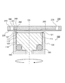
- FIG. 3 is a cross-sectional view illustrating a configuration of the fluid handling device and the flow path chip according to the embodiment.
- FIG. 4 is a plan view showing the configuration of the flow channel chip according to the embodiment.
- FIG. 5 is a plan view of the rotary member according to the embodiment.
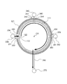
- FIG. 6 is a schematic diagram for explaining the operation of the fluid handling device according to the embodiment.
- FIG. 1A is a plan view of a flow channel chip for explaining a problem of the conventional technique.
- FIG. 1B is a bottom view of a rotary member used in combination with the flow path chip shown in FIG. 1A. 2A
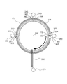
- FIG. 7 is a schematic diagram for explaining the operation of the fluid handling device according to the embodiment.
- FIG. 8 is a schematic diagram for explaining the operation of the fluid handling device according to the embodiment.
- 9A and 9B are cross-sectional views illustrating another configuration of the fluid handling device according to the embodiment.
- FIG. 3 is a cross-sectional view (a cross-sectional view taken along line AA in FIG. 4) showing a configuration of the fluid handling system (fluid handling device 100 and flow channel chip 200) according to the embodiment.
- the fluid handling device 100 has a first rotary member 110 and a second rotary member 120 arranged so as to surround the first rotary member 110.
- the first rotary member 110 and the second rotary member 120 are rotated about a central axis CA by an external drive mechanism (not shown).
- the first rotary member 110 and the second rotary member 120 are formed with a recess 140 for accommodating the plurality of rolling elements 130, and the plurality of rolling elements 130 contact the first rotary member 110 and the second rotary member 120. It is arranged to be.
- the flow path chip 200 has a substrate 210 and a film 220, and is installed in the fluid handling device 100 such that the film 220 contacts the first rotary member 110 and the second rotary member 120. In FIG. 3, the fluid handling device 100 and the flow path chip 200 are illustrated separately from each other for easy understanding.
- FIG. 4 is a plan view showing a configuration of the flow path chip 200 according to the embodiment.
- the flow path chip 200 has a substrate 210 and a film 220, and the fluid handling device 100 is configured such that the film 220 contacts the first convex portion 111 of the first rotary member 110 and the second convex portion 121 of the second rotary member 120.
- grooves (flow paths) formed on the surface of the substrate 210 on the film 220 side and diaphragms formed on the film 220 are indicated by broken lines.
- the flow path chip 200 has the substrate 210 and the film 220 (see FIG. 4).
- the substrate 210 is formed with a groove serving as a flow path and a through hole serving as an inlet or an outlet.
- the film 220 is joined to one surface of the substrate 210 so as to cover the concave portion formed in the substrate 210 and the opening of the through hole. Some regions of the film 220 function as a diaphragm.
- the groove of the substrate 210 closed by the film 220 becomes a flow path for flowing a fluid such as a reagent, a liquid sample, a gas, and a powder.
- the thickness of the substrate 210 is not particularly limited.
- the thickness of substrate 210 is 1 mm or more and 10 mm or less.
- the material of the substrate 210 is not particularly limited.
- the material of the substrate 210 can be appropriately selected from known resins and glass. Examples of the material of the substrate 210 include polyethylene terephthalate, polycarbonate, polymethyl methacrylate, polyvinyl chloride, polypropylene, polyether, polyethylene, polystyrene, silicone resin, and elastomer.
- the thickness of the film 220 is not particularly limited as long as it can function as a diaphragm.
- the thickness of the film 220 is 30 ⁇ m or more and 300 ⁇ m or less.
- the material of the film 220 is not particularly limited as long as it can function as a diaphragm.
- the material of the film 220 can be appropriately selected from known resins. Examples of the material of the film 220 include polyethylene terephthalate, polycarbonate, polymethyl methacrylate, polyvinyl chloride, polypropylene, polyether, polyethylene, polystyrene, silicone resin and elastomer.
- the film 220 is bonded to the substrate 210 by, for example, heat welding, laser welding, an adhesive, or the like.
- the flow channel chip 200 includes a first inlet 230, a first inlet 231, a first valve 232, a second inlet 240, and a second inlet 241.
- the first introduction channel 231, the second introduction channel 241 and the third introduction channel 251 correspond to the first channel in the claims
- the common channel 260 is the second channel in the claims. Is equivalent to
- the first inlet 230, the second inlet 240, and the third inlet 250 are bottomed concave portions for introducing a fluid.
- the first inlet 230, the second inlet 240, and the third inlet 250 close a through hole formed in the substrate 210 and one opening of the through hole, respectively.
- the shape and size of these inlets are not particularly limited, and can be appropriately set as needed.
- the shape of these inlets is, for example, a substantially columnar shape.
- the width of these inlets is, for example, about 2 mm.
- the type of the fluid stored in these inlets can be appropriately selected according to the use of the flow path chip 200.
- the fluid is a fluid such as a reagent, a liquid sample, or a powder.
- the first introduction channel 231, the second introduction channel 241 and the third introduction channel 251 are channels through which fluid can move.
- the upstream ends of the first introduction channel 231, the second introduction channel 241 and the third introduction channel 251 are connected to the first introduction port 230, the second introduction port 240 and the third introduction port 250, respectively.
- the downstream ends of the first introduction channel 231, the second introduction channel 241 and the third introduction channel 251 are connected to the common channel 260 at different positions.
- the first introduction flow path 231, the second introduction flow path 241 and the third introduction flow path 251 respectively close the groove formed in the substrate 210 and the opening of the groove.
- a film 220 The cross-sectional area and cross-sectional shape of these channels are not particularly limited.
- cross section of the flow path means a cross section of the flow path orthogonal to the direction in which the fluid flows.
- the cross-sectional shape of these flow paths is, for example, a substantially rectangular shape having a side length (width and depth) of about several tens of ⁇ m.
- the cross-sectional area of these channels may or may not be constant in the direction of flow of the fluid. In the present embodiment, the cross-sectional areas of these flow paths are constant.
- the first valve 232, the second valve 242, and the third valve 252 are diaphragm valves that control the flow of fluid in the first introduction flow path 231, the second introduction flow path 241, and the third introduction flow path 251, respectively. .
- the first valve 232 is disposed in the first introduction channel 231 or at a junction of the first introduction channel 231 and the common channel 260.
- the second valve 242 is disposed in the second introduction channel 241 or at a junction of the second introduction channel 241 and the common channel 260.
- the third valve 252 is disposed in the third introduction channel 251 or at a junction of the third introduction channel 251 and the common channel 260.
- the first valve 232 is disposed at the junction of the first introduction channel 231 and the common channel 260
- the second valve 242 is located at the junction of the second introduction channel 241 and the common channel 260
- the third valve 252 is disposed at the junction of the third introduction flow path 251 and the common flow path 260.
- the first valve 232, the second valve 242, and the third valve 252 are arranged on the circumference of a circle centered on the central axis CA.
- the first valve 232 has a first partition 233 and a first diaphragm 234.
- the second valve 242 has a second partition 243 and a second diaphragm 244, and the third valve 252 has a third partition 253 and a third diaphragm 254.
- the first partition 233 is disposed between the first introduction channel 231 and the common channel 260.
- the second valve 242 is disposed between the second introduction flow path 241 and the common flow path 260
- the third valve 252 is disposed between the third introduction flow path 251 and the common flow path 260.
- the first diaphragm 234 is arranged to face the first partition 233.
- the second diaphragm 244 is arranged so as to face the second partition 243
- the third diaphragm 254 is arranged so as to face the third partition 253.
- the first partition 233 functions as a valve seat of a diaphragm valve for opening and closing between the first introduction channel 231 and the common channel 260.
- the second partition 243 functions as a valve seat of a diaphragm valve for opening and closing between the second introduction channel 241 and the common channel 260
- the third partition 253 is connected to the third introduction channel 251. It functions as a valve seat of a diaphragm valve for opening and closing with the common flow channel 260.
- the shape and height of these partition walls are not particularly limited as long as the above functions can be exhibited.
- the shape of these partition walls is, for example, a quadrangular prism shape.
- the height of these partitions is the same as the depth of the introduction channel and the common channel 260, for example.
- the first diaphragm 234, the second diaphragm 244, and the third diaphragm 254 are a part of the flexible film 220 and have a substantially spherical crown shape (see FIG. 3).
- the film 220 is disposed on the substrate 210 such that each diaphragm is in non-contact and opposed to a corresponding partition.
- Each of the diaphragms bends toward a corresponding partition when pressed by a first convex portion 111 (described below) of the first rotary member 110 or a second convex portion 121 (described below) of the second rotary member 120. That is, the diaphragm functions as a valve element of the diaphragm valve.
- the first introduction flow path 231 and the common flow path 260 form a gap between the first diaphragm 234 and the first partition 233. And are in communication with each other.
- the first convex portion 121 or the second convex portion 121 is pressing the first diaphragm 234 so that the first diaphragm 234 contacts the first partition wall 233, the first introduction channel 231 and the common channel 260 Are not in communication with each other.
- the common flow channel 260 is a flow channel through which a fluid can move.
- the common flow path 260 is connected to the first introduction flow path 231 via the first valve 232, is connected to the second introduction flow path 241 via the second valve 242, and is connected via the third valve 252. Connected to the third introduction channel 251. Therefore, the fluid introduced into the first introduction port 230, the fluid introduced into the second introduction port 240, and the fluid introduced into the third introduction port 250 flow through the common flow channel 260.
- the downstream end of the common flow channel 260 is connected to the outlet 270.
- the common flow channel 260 includes a groove formed in the substrate 210 and the film 220 closing the opening of the groove.
- the cross-sectional area and the cross-sectional shape of the common flow channel 260 are not particularly limited.
- the cross-sectional shape of the common flow channel 260 is, for example, a substantially rectangular shape having a side length (width and depth) of about several tens ⁇ m.
- the cross-sectional area of the common flow channel 260 may or may not be constant in the flow direction of the fluid. In the present embodiment, the cross-sectional area of common channel 260 is constant.
- the outlet 270 is a concave part with a bottom.
- the outlet 270 functions as an air hole or functions as an outlet for extracting the fluid in the common flow channel 260.
- the outlet 270 includes a through hole formed in the substrate 210 and a film 220 closing one opening of the through hole.
- the shape and size of the outlet 270 are not particularly limited, and can be appropriately set as needed.
- the shape of the outlet 270 is, for example, a substantially columnar shape.
- the width of the outlet 270 is, for example, about 2 mm.
- FIG. 5 is a plan view of the first rotary member 110 and the second rotary member 120 of the fluid handling device 100 according to the embodiment.
- the top surface of the first protrusion 111 of the first rotary member 110 and the top surface of the second protrusion 121 of the second rotary member 120 are hatched for easy viewing.
- the fluid handling device 100 has the first rotary member 110 and the second rotary member 120 arranged so as to surround the first rotary member 110.
- the first rotary member 110 has a first convex portion 111 for pressing a diaphragm of a valve (first valve 232, second valve 242 or third valve 252) to close the valve, and has a rotating shaft (center axis). CA).
- the shape of the first rotary member 110 is substantially cylindrical.
- the second rotary member 120 is disposed so as to surround the first rotary member 110, and presses a diaphragm of a valve (the first valve 232, the second valve 242, or the third valve 252) to close the valve.
- the first rotary member 110 has a convex portion 121 and is rotatable about a rotation axis (center axis CA) separately from the first rotary member 110.
- the first convex portion 111 and the first concave portion 112 of the first rotary member 110 are arranged on the circumference of a first circle centered on the central axis CA.
- the planar shape of the first projection 111 is an arc corresponding to a part of the first circle centered on the central axis CA.
- a region where the first protrusion 111 does not exist on the circumference of the first circle is the first recess 112.
- the first protrusion 111 only needs to protrude relatively to the first recess 112, and the first recess 112 need only be recessed relatively to the first protrusion 111. That is, the first convex portion 111 only has to function as a pressing portion, and the first concave portion 112 has only to function as a non-pressing portion.
- the second convex portion 121 and the second concave portion 122 of the second rotary member 120 are arranged on the circumference of the second circle around the central axis CA.
- the planar shape of the second convex portion 121 is an arc shape corresponding to a part of the second circle centered on the central axis CA.
- a region where the second protrusion 121 does not exist on the circumference of the second circle is the second recess 122.
- the second protrusion 121 only needs to protrude relatively to the second recess 122, and the second recess 122 only needs to be recessed relatively to the second protrusion 121. That is, the second convex portion 121 only has to function as a pressing portion, and the second concave portion 122 has only to function as a non-pressing portion.
- the first projection 111 of the first rotary member 110 and the second projection 121 of the second rotary member 120 press the diaphragm of the same valve (the first valve 232, the second valve 242, or the third valve 252). Therefore, it is preferable that the distance between the first protrusion 111 and the second protrusion 121 is small. In the present embodiment, the distance between the first protrusion 111 and the second protrusion 121 is in the range of 5 to 150 ⁇ m.
- the outer surface (the surface on the second rotary member 120 side) 113 of the first rotary member 110 and the inner surface (the surface on the first rotary member 110 side) 123 of the second rotary member 120 have a plurality of A recess 140 for accommodating the rolling element 130 is formed.
- the cross-sectional shape of the recess 140 in the direction along the central axis CA is not particularly limited as long as the plurality of rolling elements 130 can be appropriately accommodated.
- the cross-sectional shape of recess 140 is substantially square (see FIG. 3).
- the size of the recess 140 is not particularly limited as long as the plurality of rolling elements 130 can appropriately contact both the first rotary member 110 and the second rotary member 120.
- the plurality of rolling elements 130 are disposed between the first rotary member 110 and the second rotary member 120, and have a function of reducing friction between the first rotary member 110 and the second rotary member 120.
- the plurality of rolling elements 130 are arranged between the first rotary member 110 and the second rotary member 120 without being accommodated in a member (for example, a race ring) other than the first rotary member 110 and the second rotary member 120. Have been. Therefore, the plurality of rolling elements 130 are in direct contact with the first rotary member 110 and the second rotary member 120.
- the plurality of rolling elements 130 are housed in the above-described recess 140.
- the plurality of rolling elements 130 are arranged so as to be in direct contact with the first rotary member 110 and the second rotary member 120, the plurality of rolling elements 130 are held by a holder for keeping the interval between the plurality of rolling elements 130 constant. It may be.
- the plurality of rolling elements 130 have the same size and are slightly larger than the recess 140. Therefore, the first rotary member 110 and the second rotary member 120 are slightly separated from each other by disposing the plurality of rolling elements 130 in the recess 140. In the present embodiment, the distance between first rotary member 110 and second rotary member 120 is in the range of 5 to 150 ⁇ m.
- the shape of the rolling element 130 is not particularly limited as long as the friction between the first rotary member 110 and the second rotary member 120 can be reduced.
- the rolling element 130 is, for example, a ball (ball) or a roller (roller). Examples of the roller include a cylindrical roller, a conical roller, a needle-shaped roller, and the like.
- the material of the rolling element 130 is not particularly limited as long as it has necessary strength, wear resistance, corrosion resistance, and the like. Examples of the material of the rolling element 130 include ceramics, stainless steel, soda glass, brass, tungsten, high carbon chromium bearing steel, resin, and the like. In the present embodiment, rolling elements 130 are bearing balls made of high carbon chromium bearing steel.
- the first convex portion 111 and the second convex portion 121 are shown with hatching when they are in contact with the film 220 of the flow path chip 200, and when they are not in contact with each other.
- the first inlet 230 contains the first liquid
- the second inlet 240 contains the second liquid
- the third inlet 250 contains the third liquid.
- the first inlet 230, the second inlet 240, and the third inlet 250 are assumed to be pressurized.
- the first rotary member 110 is rotated so that the first concave portion 112 is located on the first valve 232 and the first convex portion 111 is located on the second valve 242 and the third valve 252.
- the second rotary member 120 By rotating the second rotary member 120 so that the second concave portion 122 is located on the one valve 232 and the second convex portion 121 is located on the second valve 242 and the third valve 252, the first valve 232 is The second valve 242 and the third valve 252 are closed.
- the first liquid in the first inlet 230 moves to the outlet 270 through the first inlet channel 231, the first valve 232, and the common channel 260.
- the second valve 242 and the third valve 252 are closed, the second liquid in the second inlet 240 and the third liquid in the third inlet 250 do not flow into the common flow channel 260.
- the third liquid in the third inlet 250 is to be flowed into the common channel 260.
- the first rotary member 110 is rotated until the first concave portion 112 is positioned on the third valve 252, and the second rotary member 120 is rotated until the second concave portion 122 is positioned on the third valve 252. Need to be done.
- the positions of the first concave portion 112 and the second concave portion 122 do not coincide with each other until the third valve 252 is reached. To do. For example, as shown in FIG.
- the plurality of rolling elements 130 are not housed in members (for example, races) other than the first rotary member 110 and the second rotary member 120, It is directly disposed in a concave portion 140 formed between the first rotary member 110 and the second rotary member 120.
- the size of the concave portion 140 affects the distance between the first rotary member 110 and the second rotary member 120 (that is, the distance between the first convex portion 111 and the second convex portion 121).
- the plurality of rolling elements 130 are directly arranged in the concave portion 140 as in the present embodiment, only the dimensional error of the concave portion 140 is caused by the distance between the first rotary member 110 and the second rotary member 120 (that is, the first convex portion). (The distance between the portion 111 and the second convex portion 121). Therefore, in the fluid handling device 100 according to the present embodiment, the friction between the first rotary member 110 and the second rotary member 120 is small, and the distance between the first rotary member 110 and the second rotary member 120 (ie, the first rotary member 110 and the second rotary member 120). The variation in the distance between the convex portion 111 and the second convex portion 121) is also small. As a result, even if the fluid handling apparatus 100 according to the present embodiment has a plurality of rotary members, it is possible to accurately control the opening and closing of the valve.
- a concave portion 140 for accommodating the rolling element 130 may be formed only on the outer side surface 113 of the first rotary member 110, or as shown in FIG. 9B, the second rotary member 120
- the recess 140 for accommodating the rolling element 130 may be formed only on the inner side surface 123 of the first member.
- the fluid handling device of the present invention is useful in various applications such as clinical tests, food tests, and environmental tests.
Landscapes
- Chemical & Material Sciences (AREA)
- General Engineering & Computer Science (AREA)
- Engineering & Computer Science (AREA)
- Health & Medical Sciences (AREA)
- Chemical Kinetics & Catalysis (AREA)
- Dispersion Chemistry (AREA)
- Mechanical Engineering (AREA)
- Clinical Laboratory Science (AREA)
- Analytical Chemistry (AREA)
- General Health & Medical Sciences (AREA)
- Hematology (AREA)
- Life Sciences & Earth Sciences (AREA)
- Pathology (AREA)
- Immunology (AREA)
- General Physics & Mathematics (AREA)
- Biochemistry (AREA)
- Physics & Mathematics (AREA)
- Organic Chemistry (AREA)
- Automatic Analysis And Handling Materials Therefor (AREA)
- Physical Or Chemical Processes And Apparatus (AREA)
Abstract
流体取扱装置は、バルブのダイヤフラムを押圧してバルブを閉じさせるための第1凸部を有し、回転軸を中心として回転可能な第1ロータリー部材と、第1ロータリー部材を取り囲むように配置され、バルブのダイヤフラムを押圧してバルブを閉じさせるための第2凸部を有し、回転軸を中心として第1ロータリー部材とは別個に回転可能な第2ロータリー部材と、第1ロータリー部材と第2ロータリー部材との間に配置され、第1ロータリー部材および第2ロータリー部材に接触している複数の転動体と、を有する。
Description
本発明は、流体取扱装置および流体取扱システムに関する。
近年、タンパク質や核酸などの微量な物質の分析を高精度かつ高速に行うために、流路チップが使用されている。流路チップは、分析に必要な試薬および試料の量が少なくてよいという利点を有しており、臨床検査や食物検査、環境検査などの様々な用途での使用が期待されている。たとえば、特許文献1には、複数のマイクロバルブを有する流路チップと、複数のマイクロバルブの開閉を制御するための加圧部とを有する、マイクロバルブユニットが開示されている。流路チップにおいて、複数のマイクロバルブは、同一円周上に配置されている。また、加圧部は、平面視形状が円弧状の当接面を有している。加圧部を回転させることで、加圧部の当接面が移動する。これにより、マイクロバルブのダイヤフラムは、加圧部により押圧されたり、押圧されなくなったりする。マイクロバルブは、加圧部により押圧されているときは閉じ、加圧部により押圧されていないときは開く。
上記のとおり、特許文献1に記載の装置(マイクロバルブユニット)では、平面視形状が円弧状の凸部(端面)を有するロータリー部材(加圧部)を回転させて、複数のバルブ(マイクロバルブ)の開閉を制御している。このような装置において、流路チップが多数のバルブを有している場合、バルブを意図した順番で開閉できないことがある。この問題について、図1A~図2Bを参照して説明する。
図1Aは、従来の技術の問題点を説明するための流路チップの平面図である。図1Bは、図1Aに示される流路チップと組み合わせて使用されるロータリー部材の底面図である。図1Aに示されるように、流路チップは、第1導入口10、第1導入流路11、第1バルブ12、第2導入口20、第2導入流路21、第2バルブ22、第3導入口30、第3導入流路31、第3バルブ32、共通流路40および取出口41を有する。第1導入流路11の上流端は、第1導入口10に接続されており、第1導入流路11の下流端は、共通流路40の上流端に接続されている。第2導入流路21の上流端は、第2導入口20に接続されており、第2導入流路21の下流端は、共通流路40の上流端に接続されている。第3導入流路31の上流端は、第3導入口30に接続されており、第3導入流路31の下流端は、共通流路40の上流端に接続されている。第1導入流路11、第2導入流路21および第3導入流路31には、第1バルブ12、第2バルブ22および第3バルブ32がそれぞれ設けられている。共通流路40の下流端は、取出口41に接続されている。
また、図1Bに示されるように、ロータリー部材は、第1バルブ12、第2バルブ22および第3バルブ32を押圧するための平面視形状が円弧状の凸部50と、凸部50と同一円周上に配置された凹部51と、を有する。図1Bでは、凸部50の底面(流路チップに接触する面)にハッチングを付している。第1バルブ12、第2バルブ22および第3バルブ32は、凸部50により押圧されているときは閉じ、凸部50により押圧されていないときは開く。
たとえば、図2Aに示されるように、凹部51が第1バルブ12上に位置し、凸部50が第2バルブ22および第3バルブ32上に位置するようにロータリー部材を回転させる。この場合、第1バルブ12が開き、第1導入口10内の流体は、第1導入流路11および共通流路40を通って取出口41に流れることができる。一方、第2バルブ22および第3バルブ32は閉じるため、第2導入口20内の液体および第3導入口30内の流体は、取出口41に向けて流れることができない。
この後、第3導入口30内の流体を取出口41に向けて流したい場合、凹部51が第3バルブ32上に位置し、凸部50が第1バルブ12および第2バルブ22上に位置するようにロータリー部材を回転させる。しかしながら、図2Bに示されるように、ロータリー部材を回転させている間に、一時的に、凹部51が第2バルブ22上に位置し、凸部50が第1バルブ12および第3バルブ32上に位置することとなる。したがって、第2導入口20内の流体を流す意図が無いのに、第2導入口20内の流体が、取出口41に向けて流れてしまうおそれがある。
以上のように、従来の装置には、流路チップが多数のバルブを有している場合、1つのロータリー部材だけではバルブを意図した順番で開閉するように制御することは難しい。そのため、平面視形状が円弧状の凸部を有するロータリー部材を複数配置されている流体取扱装置が望まれている。
本発明者は、複数のロータリー部材を有する流体取扱装置について検討したところ、複数のロータリー部材が回転軸を中心として同心円状に配置されていることから、回転時に、内側に配置されているロータリー部材(第1ロータリー部材)と、外側に配置されているロータリー部材(第2ロータリー部材)との間で摩擦が生じ、回転性が悪くなることで所望する位置でバルブが押圧されにくくなることがわかった。
そこで、本発明者は、2つのロータリー部材間の摩擦を軽減するために、一方のロータリー部材に形成された凹部に市販のボールベアリングを取り付けたところ、ロータリー部材間の摩擦を軽減することができたが、2つのロータリー部材間の間隔にばらつきが生じてしまうことがわかった。たとえば、1つのバルブに対して内側の第1ロータリー部材の第1凸部および外側の第2ロータリー部材の第2凸部の両方を接触させたい場合、第1凸部と第2凸部との間隔が狭いことが好ましい。しかしながら、上記のようにボールベアリングを取り付けることにより2つのロータリー部材間の間隔にばらつきが生じてしまうと、1つのバルブに対して第1凸部および第2凸部の両方が適切に接触することができなくなり、バルブの開閉を適切に制御できなくなるおそれがある。
本発明は、かかる点に鑑みてなされたものであり、複数のロータリー部材を有していても、精度よくバルブの開閉を制御することができる流体取扱装置および流体取扱システムを提供することを目的とする。
本発明に係る流体取扱装置は、第1流路、第2流路、および前記第1流路と前記第2流路との間に配置されたバルブを有する流路チップ内の流体を制御するための流体取扱装置であって、前記バルブのダイヤフラムを押圧して前記バルブを閉じさせるための第1凸部を有し、回転軸を中心として回転可能な第1ロータリー部材と、前記第1ロータリー部材を取り囲むように配置され、前記バルブのダイヤフラムを押圧して前記バルブを閉じさせるための第2凸部を有し、前記回転軸を中心として前記第1ロータリー部材とは別個に回転可能な第2ロータリー部材と、前記第1ロータリー部材と前記第2ロータリー部材との間に配置され、前記第1ロータリー部材および前記第2ロータリー部材に接触している複数の転動体と、を有する。
本発明に係る流体取扱システムは、第1流路、第2流路、および前記第1流路と前記第2流路との間に配置されたバルブを有する流路チップと、本発明に係る流体取扱装置と、を有する。
本発明によれば、複数のロータリー部材を有していても、精度よくバルブの開閉を制御することができる流体取扱装置および流体取扱システムを提供することができる。
以下、本発明の実施の形態について、図面を参照して詳細に説明する。
[実施の形態]
(流体取扱装置および流路チップの構成)
図3は、実施の形態に係る流体取扱システム(流体取扱装置100および流路チップ200)の構成を示す断面図(図4のA-A線の断面図)である。図3に示されるように、流体取扱装置100は、第1ロータリー部材110および第1ロータリー部材110を取り囲むように配置されている第2ロータリー部材120を有する。第1ロータリー部材110および第2ロータリー部材120は、図示しない外部の駆動機構により中心軸CAを中心に回転させられる。第1ロータリー部材110および第2ロータリー部材120には、複数の転動体130を収容するための凹部140が形成され、複数の転動体130は、第1ロータリー部材110および第2ロータリー部材120に接触するように配置されている。流路チップ200は、基板210およびフィルム220を有し、フィルム220が第1ロータリー部材110および第2ロータリー部材120に接触するように流体取扱装置100に設置される。なお、図3では、流体取扱装置100および流路チップ200の構成をわかりやすくするために、これらを離して図示している。
(流体取扱装置および流路チップの構成)
図3は、実施の形態に係る流体取扱システム(流体取扱装置100および流路チップ200)の構成を示す断面図(図4のA-A線の断面図)である。図3に示されるように、流体取扱装置100は、第1ロータリー部材110および第1ロータリー部材110を取り囲むように配置されている第2ロータリー部材120を有する。第1ロータリー部材110および第2ロータリー部材120は、図示しない外部の駆動機構により中心軸CAを中心に回転させられる。第1ロータリー部材110および第2ロータリー部材120には、複数の転動体130を収容するための凹部140が形成され、複数の転動体130は、第1ロータリー部材110および第2ロータリー部材120に接触するように配置されている。流路チップ200は、基板210およびフィルム220を有し、フィルム220が第1ロータリー部材110および第2ロータリー部材120に接触するように流体取扱装置100に設置される。なお、図3では、流体取扱装置100および流路チップ200の構成をわかりやすくするために、これらを離して図示している。
図4は、実施の形態に係る流路チップ200の構成を示す平面図である。流路チップ200は、基板210およびフィルム220を有し、フィルム220が第1ロータリー部材110の第1凸部111および第2ロータリー部材120の第2凸部121に接触するように流体取扱装置100に設置される。図4では、基板210のフィルム220側の面に形成された溝(流路)と、フィルム220に形成されたダイヤフラムを破線で示している。
前述のとおり、流路チップ200は、基板210およびフィルム220を有する(図4参照)。基板210には、流路となるための溝、および導入口または取出口となる貫通孔が形成されている。フィルム220は、基板210に形成された凹部および貫通孔の開口部を塞ぐように基板210の一方の面に接合されている。フィルム220の一部の領域は、ダイヤフラムとして機能する。フィルム220により塞がれた基板210の溝は、試薬や液体試料、気体、粉体などの流体を流すための流路となる。
基板210の厚みは、特に限定されない。たとえば、基板210の厚みは、1mm以上10mm以下である。また、基板210の材料も、特に限定されない。たとえば、基板210の材料は、公知の樹脂およびガラスから適宜選択されうる。基板210の材料の例には、ポリエチレンテレフタレート、ポリカーボネート、ポリメタクリル酸メチル、ポリ塩化ビニル、ポリプロピレン、ポリエーテル、ポリエチレン、ポリスチレン、シリコーン樹脂およびエラストマーが含まれる。
フィルム220の厚みは、ダイヤフラムとして機能することが可能であれば特に限定されない。たとえば、フィルム220の厚みは、30μm以上300μm以下である。また、フィルム220の材料も、ダイヤフラムとして機能することが可能であれば特に限定されない。たとえば、フィルム220の材料は、公知の樹脂から適宜選択されうる。フィルム220の材料の例には、ポリエチレンテレフタレート、ポリカーボネート、ポリメタクリル酸メチル、ポリ塩化ビニル、ポリプロピレン、ポリエーテル、ポリエチレン、ポリスチレン、シリコーン樹脂およびエラストマーが含まれる。フィルム220は、例えば、熱溶着やレーザ溶着、接着剤などにより基板210に接合される。
図4に示されるように、本実施の形態に係る流路チップ200は、第1導入口230、第1導入流路231、第1バルブ232、第2導入口240、第2導入流路241、第2バルブ242、第3導入口250、第3導入流路251、第3バルブ252、共通流路260および取出口270を有する。第1導入流路231、第2導入流路241および第3導入流路251は、特許請求の範囲における第1流路に相当し、共通流路260は、特許請求の範囲における第2流路に相当する。
第1導入口230、第2導入口240および第3導入口250は、流体を導入するための有底の凹部である。本実施の形態では、第1導入口230、第2導入口240および第3導入口250は、それぞれ、基板210に形成されている貫通孔と、当該貫通孔の一方の開口部を閉塞しているフィルム220とから構成されている。これらの導入口の形状および大きさは、特に限定されず、必要に応じて適宜設定されうる。これらの導入口の形状は、例えば、略円柱形状である。これらの導入口の幅は、例えば2mm程度である。これらの導入口に収容される流体の種類は、流路チップ200の用途に応じて適宜選択されうる。当該流体は、試薬や液体試料、粉体などの流体である。
第1導入流路231、第2導入流路241および第3導入流路251は、その内部を流体が移動しうる流路である。第1導入流路231、第2導入流路241および第3導入流路251の上流端は、それぞれ、第1導入口230、第2導入口240および第3導入口250に接続されている。第1導入流路231、第2導入流路241および第3導入流路251の下流端は、それぞれ異なる位置で共通流路260に接続されている。本実施の形態では、第1導入流路231、第2導入流路241および第3導入流路251は、それぞれ、基板210に形成されている溝と、当該溝の開口部を閉塞しているフィルム220とから構成されている。これらの流路の断面積および断面形状は、特に限定されない。本明細書において、「流路の断面」とは、流体が流れる方向に直交する流路の断面を意味する。これらの流路の断面形状は、例えば、一辺の長さ(幅および深さ)が数十μm程度の略矩形状である。これらの流路の断面積は、流体の流れ方向において、一定であってもよいし、一定でなくてもよい。本実施の形態では、これらの流路の断面積は、一定である。
第1バルブ232、第2バルブ242および第3バルブ252は、それぞれ、第1導入流路231、第2導入流路241および第3導入流路251内の流体の流れを制御するダイヤフラムバルブである。第1バルブ232は、第1導入流路231内または第1導入流路231と共通流路260との合流部に配置される。第2バルブ242は、第2導入流路241内または第2導入流路241と共通流路260との合流部に配置される。第3バルブ252は、第3導入流路251内または第3導入流路251と共通流路260との合流部に配置される。本実施の形態では、第1バルブ232は第1導入流路231と共通流路260との合流部に配置され、第2バルブ242は第2導入流路241と共通流路260との合流部に配置され、第3バルブ252は第3導入流路251と共通流路260との合流部に配置されている。また、第1バルブ232、第2バルブ242および第3バルブ252は、中心軸CAを中心とする円の円周上に配置されている。
第1バルブ232は、第1隔壁233および第1ダイヤフラム234を有する。同様に、第2バルブ242は、第2隔壁243および第2ダイヤフラム244を有し、第3バルブ252は、第3隔壁253および第3ダイヤフラム254を有する。本実施の形態では、第1隔壁233は、第1導入流路231と共通流路260との間に配置されている。同様に、第2バルブ242は、第2導入流路241と共通流路260との間に配置されており、第3バルブ252は、第3導入流路251と共通流路260との間に配置されている。また、第1ダイヤフラム234は、第1隔壁233と対向するように配置されている。同様に、第2ダイヤフラム244は、第2隔壁243と対向するように配置されており、第3ダイヤフラム254は、第3隔壁253と対向するように配置されている。
第1隔壁233は、第1導入流路231と共通流路260との間を開閉するためのダイヤフラムバルブの弁座として機能する。同様に、第2隔壁243は、第2導入流路241と共通流路260との間を開閉するためのダイヤフラムバルブの弁座として機能し、第3隔壁253は、第3導入流路251と共通流路260との間を開閉するためのダイヤフラムバルブの弁座として機能する。これらの隔壁の形状および高さは、上記の機能を発揮することができれば、特に限定されない。これらの隔壁の形状は、例えば、四角柱形状である。これらの隔壁の高さは、例えば、導入流路および共通流路260の深さと同じである。
第1ダイヤフラム234、第2ダイヤフラム244および第3ダイヤフラム254は、可撓性を有するフィルム220の一部であり、略球冠形状を有している(図3参照)。フィルム220は、それぞれのダイヤフラムが対応する隔壁に非接触でかつ対向するように基板210上に配置されている。それぞれのダイヤフラムは、第1ロータリー部材110の第1凸部111(後述)または第2ロータリー部材120の第2凸部121(後述)により押圧されたときに対応する隔壁に向かって撓む。すなわち、ダイヤフラムは、ダイヤフラムバルブの弁体として機能する。たとえば、第1凸部121および第2凸部121が第1ダイヤフラム234を押圧していないとき、第1導入流路231および共通流路260は、第1ダイヤフラム234および第1隔壁233の隙間を介して互いに連通した状態となる。一方、第1ダイヤフラム234が第1隔壁233に接触するように第1凸部121または第2凸部121が第1ダイヤフラム234を押圧しているとき、第1導入流路231および共通流路260は互いに連通しない状態となる。
共通流路260は、その内部を流体が移動しうる流路である。共通流路260は、第1バルブ232を介して第1導入流路231に接続されており、第2バルブ242を介して第2導入流路241に接続されており、第3バルブ252を介して第3導入流路251に接続されている。したがって、共通流路260には、第1導入口230に導入された流体、第2導入口240に導入された流体、および第3導入口250に導入された流体が流れる。共通流路260の下流端は、取出口270に接続されている。本実施の形態では、共通流路260は、基板210に形成されている溝と、当該溝の開口部を閉塞しているフィルム220とから構成されている。共通流路260の断面積および断面形状は、特に限定されない。共通流路260の断面形状は、例えば、一辺の長さ(幅および深さ)が数十μm程度の略矩形状である。共通流路260の断面積は、流体の流れ方向において、一定であってもよいし、一定でなくてもよい。本実施の形態では、共通流路260の断面積は、一定である。
取出口270は、有底の凹部である。取出口270は、空気孔として機能したり、共通流路260内の流体を取り出すための取り出し口として機能したりする。本実施の形態では、取出口270は、基板210に形成されている貫通孔と、当該貫通孔の一方の開口部を閉塞しているフィルム220とから構成されている。取出口270の形状および大きさは、特に限定されず、必要に応じて適宜設定されうる。取出口270の形状は、例えば、略円柱形状である。取出口270の幅は、例えば2mm程度である。
図5は、実施の形態に係る流体取扱装置100の第1ロータリー部材110および第2ロータリー部材120の平面図である。図5では、見やすくするために、第1ロータリー部材110の第1凸部111の天面および第2ロータリー部材120の第2凸部121の天面にハッチングを付している。
前述のとおり、流体取扱装置100は、第1ロータリー部材110および第1ロータリー部材110を取り囲むように配置されている第2ロータリー部材120を有する。第1ロータリー部材110は、バルブ(第1バルブ232、第2バルブ242または第3バルブ252)のダイヤフラムを押圧してバルブを閉じさせるための第1凸部111を有し、回転軸(中心軸CA)を中心として回転可能である。第1ロータリー部材110の形状は略円柱状である。第2ロータリー部材120は、第1ロータリー部材110を取り囲むように配置され、バルブ(第1バルブ232、第2バルブ242または第3バルブ252)のダイヤフラムを押圧してバルブを閉じさせるための第2凸部121を有し、回転軸(中心軸CA)を中心として第1ロータリー部材110とは別個に回転可能である。
第1ロータリー部材110の第1凸部111および第1凹部112は、中心軸CAを中心とする第1円の円周上に配置されている。本実施の形態では、第1凸部111の平面視形状は、中心軸CAを中心とする第1円の一部に対応する円弧状である。第1円の円周上において第1凸部111が存在しない領域が、第1凹部112である。
なお、第1凸部111は、第1凹部112に対して相対的に突出していればよく、第1凹部112は、第1凸部111に対して相対的に凹んでいればよい。すなわち、第1凸部111は、押圧部として機能できればよく、第1凹部112は、非押圧部として機能できればよい。
また、第2ロータリー部材120の第2凸部121および第2凹部122は、中心軸CAを中心とする第2円の円周上に配置されている。本実施の形態では、第2凸部121の平面視形状は、中心軸CAを中心とする第2円の一部に対応する円弧状である。第2円の円周上において第2凸部121が存在しない領域が、第2凹部122である。
なお、第2凸部121は、第2凹部122に対して相対的に突出していればよく、第2凹部122は、第2凸部121に対して相対的に凹んでいればよい。すなわち、第2凸部121は、押圧部として機能できればよく、第2凹部122は、非押圧部として機能できればよい。
第1ロータリー部材110の第1凸部111および第2ロータリー部材120の第2凸部121は、同一のバルブ(第1バルブ232、第2バルブ242または第3バルブ252)のダイヤフラムを押圧することから、第1凸部111と第2凸部121との間隔は小さいことが好ましい。本実施の形態では、第1凸部111と第2凸部121との間隔は、5~150μmの範囲内である。
本実施の形態では、第1ロータリー部材110の外側面(第2ロータリー部材120側の面)113および第2ロータリー部材120の内側面(第1ロータリー部材110側の面)123には、複数の転動体130を収容するための凹部140が形成されている。中心軸CAに沿う方向の凹部140の断面形状は、複数の転動体130を適切に収容することができれば、特に限定されない。本実施の形態では、凹部140の断面形状は略正方形である(図3参照)。また、凹部140の大きさも、複数の転動体130が第1ロータリー部材110および第2ロータリー部材120の両方に適切に接触できれば、特に限定されない。
複数の転動体130は、第1ロータリー部材110と第2ロータリー部材120との間に配置され、第1ロータリー部材110と第2ロータリー部材120との間の摩擦を低減させる機能を担っている。複数の転動体130は、第1ロータリー部材110および第2ロータリー部材120以外の部材(例えば軌道輪)に収容されることなく、第1ロータリー部材110と第2ロータリー部材120との間にそのまま配置されている。したがって、複数の転動体130は、第1ロータリー部材110および第2ロータリー部材120に直接接触している。本実施の形態では、複数の転動体130は、前述の凹部140に収容されている。なお、複数の転動体130は、第1ロータリー部材110および第2ロータリー部材120に直接接触するように配置されていれば、複数の転動体130間の間隔を一定とするための保持器により保持されていてもよい。複数の転動体130の大きさは、同一であり、かつ凹部140よりもわずかに大きい。したがって、複数の転動体130を凹部140内に配置することで、第1ロータリー部材110と第2ロータリー部材120とはわずかに離間する。本実施の形態では、第1ロータリー部材110と第2ロータリー部材120との間隔は、5~150μmの範囲内である。
転動体130の形状は、第1ロータリー部材110と第2ロータリー部材120との間の摩擦を低減させることができれば、特に限定されない。転動体130は、例えばタマ(ボール)またはコロ(ローラ)である。コロの例には、円筒コロ、円錐コロ、針状コロなどが含まれる。また、転動体130の材料は、必要な強度、耐摩耗性、耐食性などを有していれば特に限定されない。転動体130の材料の例には、セラミックス、ステンレス鋼、ソーダガラス、真鍮、タングステン、高炭素クロム軸受鋼、樹脂などが含まれる。本実施の形態では、転動体130は、高炭素クロム軸受鋼製のベアリングボールである。
(流体取扱装置の動作)
次に、図6~8を参照しながら、流体取扱装置100の動作について説明する。説明の便宜上、図6~8では、第1凸部111および第2凸部121について、流路チップ200のフィルム220に当接している場合はハッチングを付して図示し、当接していない場合は図示しないこととする。なお、第1導入口230には第1液体が収容されており、第2導入口240には第2液体が収容されており、第3導入口250には、第3液体が収容されており、第1導入口230、第2導入口240および第3導入口250は、加圧されているものとする。
次に、図6~8を参照しながら、流体取扱装置100の動作について説明する。説明の便宜上、図6~8では、第1凸部111および第2凸部121について、流路チップ200のフィルム220に当接している場合はハッチングを付して図示し、当接していない場合は図示しないこととする。なお、第1導入口230には第1液体が収容されており、第2導入口240には第2液体が収容されており、第3導入口250には、第3液体が収容されており、第1導入口230、第2導入口240および第3導入口250は、加圧されているものとする。
まず、第1バルブ232の上に第1凹部112が位置し、第2バルブ242および第3バルブ252の上に第1凸部111が位置するように第1ロータリー部材110を回転させるとともに、第1バルブ232上に第2凹部122が位置し、第2バルブ242および第3バルブ252の上に第2凸部121が位置するように第2ロータリー部材120を回転させて、第1バルブ232を開かせ、第2バルブ242および第3バルブ252を閉じさせる。これにより、図6に示されるように、第1導入口230内の第1液体は、第1導入流路231、第1バルブ232および共通流路260を通って取出口270に移動する。このとき、第2バルブ242および第3バルブ252は閉じているため、第2導入口240内の第2液体および第3導入口250内の第3液体が共通流路260に流れ込むことはない。
次に、第3導入口250内の第3液体を共通流路260に流したいとする。この場合、第3バルブ252の上に第1凹部112が位置するまで第1ロータリー部材110を回転させ、かつ第3バルブ252の上に第2凹部122が位置するまで第2ロータリー部材120を回転させる必要がある。このとき、第1ロータリー部材110および第2ロータリー部材120を互いに逆方向に回転させるなどして、第3バルブ252に到達するまでの間に第1凹部112および第2凹部122の位置が一致しないようにする。たとえば、図7に示されるように、第2ロータリー部材120を回転させている途中に、第2バルブ242の上に第2凹部122が位置しても、第2バルブ242のダイヤフラムは、第1ロータリー部材110の第1凸部111により押圧されている。したがって、第1ロータリー部材110または第2ロータリー部材120を回転させている途中に、第2バルブ242の上を第1凹部112または第2凹部122が通過しても、第2導入口240内の第2液体が共通流路260に流れ込むことはない。
そして、第3バルブ252の上に第1凹部112が位置し、第1バルブ232および第2バルブ242の上に第1凸部111が位置したら、第1ロータリー部材110の回転を止める。また、第3バルブ252の上に第2凹部122が位置し、第1バルブ232および第2バルブ242の上に第2凸部121が位置したら、第2ロータリー部材120の回転を止める。これにより、第3バルブ252のみが開く。これにより、図8に示されるように、第3導入口250内の第3液体は、第3導入流路251、第3バルブ252および共通流路260を通って取出口270に移動する。このとき、第1バルブ232および第2バルブ242は閉じているため、第1導入口230内の第1液体および第2導入口240内の第2液体が共通流路260に流れ込むことはない。
以上の手順により、第1ロータリー部材110または第2ロータリー部材120を回転させている途中に意図しないバルブを開かせることなく、第1ロータリー部材110または第2ロータリー部材120を回転させることで複数のバルブの開閉を制御することができる。
(効果)
以上のように、本実施の形態に係る流体取扱装置100では、複数の転動体130が、第1ロータリー部材110および第2ロータリー部材120以外の部材(例えば軌道輪)に収容されることなく、第1ロータリー部材110と第2ロータリー部材120との間に形成された凹部140に直接配置されている。たとえば、第1ロータリー部材110の外側面113または第2ロータリー部材120の内側面に凹部140を形成し、この凹部140に軌道輪などを有する市販のボールベアリングを嵌め込んだ場合、凹部140の寸法誤差およびボールベアリングの軌道輪の寸法誤差の合計が第1ロータリー部材110と第2ロータリー部材120との間隔(すなわち第1凸部111と第2凸部121との間隔)に影響してしまう。しかしながら、本実施の形態のように、複数の転動体130を凹部140に直接配置した場合、凹部140の寸法誤差のみが第1ロータリー部材110と第2ロータリー部材120との間隔(すなわち第1凸部111と第2凸部121との間隔)に影響する。したがって、本実施の形態に係る流体取扱装置100では、第1ロータリー部材110と第2ロータリー部材120との摩擦が小さく、かつ第1ロータリー部材110と第2ロータリー部材120との間隔(すなわち第1凸部111と第2凸部121との間隔)のばらつきも小さい。その結果、本実施の形態に係る流体取扱装置100は、複数のロータリー部材を有していても、精度よくバルブの開閉を制御することができる。
以上のように、本実施の形態に係る流体取扱装置100では、複数の転動体130が、第1ロータリー部材110および第2ロータリー部材120以外の部材(例えば軌道輪)に収容されることなく、第1ロータリー部材110と第2ロータリー部材120との間に形成された凹部140に直接配置されている。たとえば、第1ロータリー部材110の外側面113または第2ロータリー部材120の内側面に凹部140を形成し、この凹部140に軌道輪などを有する市販のボールベアリングを嵌め込んだ場合、凹部140の寸法誤差およびボールベアリングの軌道輪の寸法誤差の合計が第1ロータリー部材110と第2ロータリー部材120との間隔(すなわち第1凸部111と第2凸部121との間隔)に影響してしまう。しかしながら、本実施の形態のように、複数の転動体130を凹部140に直接配置した場合、凹部140の寸法誤差のみが第1ロータリー部材110と第2ロータリー部材120との間隔(すなわち第1凸部111と第2凸部121との間隔)に影響する。したがって、本実施の形態に係る流体取扱装置100では、第1ロータリー部材110と第2ロータリー部材120との摩擦が小さく、かつ第1ロータリー部材110と第2ロータリー部材120との間隔(すなわち第1凸部111と第2凸部121との間隔)のばらつきも小さい。その結果、本実施の形態に係る流体取扱装置100は、複数のロータリー部材を有していても、精度よくバルブの開閉を制御することができる。
(変形例)
なお、上記実施の形態では、第1ロータリー部材110の外側面113および第2ロータリー部材120の内側面に凹部140を形成した流体取扱層装置100について説明したが、本発明はこれに限定されない。たとえば、図9Aに示されるように、第1ロータリー部材110の外側面113のみに転動体130を収容する凹部140を形成してもよいし、図9Bに示されるように、第2ロータリー部材120の内側面123のみに転動体130を収容する凹部140を形成してもよい。
なお、上記実施の形態では、第1ロータリー部材110の外側面113および第2ロータリー部材120の内側面に凹部140を形成した流体取扱層装置100について説明したが、本発明はこれに限定されない。たとえば、図9Aに示されるように、第1ロータリー部材110の外側面113のみに転動体130を収容する凹部140を形成してもよいし、図9Bに示されるように、第2ロータリー部材120の内側面123のみに転動体130を収容する凹部140を形成してもよい。
本出願は、2018年7月12日出願の特願2018-132249に基づく優先権を主張する。当該出願明細書および図面に記載された内容は、すべて本願明細書に援用される。
本発明の流体取扱装置は、例えば、臨床検査や食物検査、環境検査などの様々な用途において有用である。
10 第1導入口
11 第1導入流路
12 第1バルブ
20 第2導入口
21 第2導入流路
22 第2バルブ
30 第3導入口
31 第3導入流路
32 第3バルブ
40 共通流路
41 取出口
50 ロータリー部材の凸部
51 ロータリー部材の凹部
100 流体取扱装置
110 第1ロータリー部材
111 第1凸部
112 第1凹部
113 第1ロータリー部材の外側面
120 第2ロータリー部材
121 第2凸部
122 第2凹部
123 第2ロータリー部材の内側面
130 転動体
140 凹部
200 流路チップ
210 基板
220 フィルム
230 第1導入口
231 第1導入流路
232 第1バルブ
233 第1隔壁
234 第1ダイヤフラム
240 第2導入口
241 第2導入流路
242 第2バルブ
243 第2隔壁
244 第2ダイヤフラム
250 第3導入口
251 第3導入流路
252 第3バルブ
253 第3隔壁
254 第3ダイヤフラム
260 共通流路
270 取出口
CA 中心軸
11 第1導入流路
12 第1バルブ
20 第2導入口
21 第2導入流路
22 第2バルブ
30 第3導入口
31 第3導入流路
32 第3バルブ
40 共通流路
41 取出口
50 ロータリー部材の凸部
51 ロータリー部材の凹部
100 流体取扱装置
110 第1ロータリー部材
111 第1凸部
112 第1凹部
113 第1ロータリー部材の外側面
120 第2ロータリー部材
121 第2凸部
122 第2凹部
123 第2ロータリー部材の内側面
130 転動体
140 凹部
200 流路チップ
210 基板
220 フィルム
230 第1導入口
231 第1導入流路
232 第1バルブ
233 第1隔壁
234 第1ダイヤフラム
240 第2導入口
241 第2導入流路
242 第2バルブ
243 第2隔壁
244 第2ダイヤフラム
250 第3導入口
251 第3導入流路
252 第3バルブ
253 第3隔壁
254 第3ダイヤフラム
260 共通流路
270 取出口
CA 中心軸
Claims (5)
- 第1流路、第2流路、および前記第1流路と前記第2流路との間に配置されたバルブを有する流路チップ内の流体を制御するための流体取扱装置であって、
前記バルブのダイヤフラムを押圧して前記バルブを閉じさせるための第1凸部を有し、回転軸を中心として回転可能な第1ロータリー部材と、
前記第1ロータリー部材を取り囲むように配置され、前記バルブのダイヤフラムを押圧して前記バルブを閉じさせるための第2凸部を有し、前記回転軸を中心として前記第1ロータリー部材とは別個に回転可能な第2ロータリー部材と、
前記第1ロータリー部材と前記第2ロータリー部材との間に配置され、前記第1ロータリー部材および前記第2ロータリー部材に接触している複数の転動体と、
を有する、流体取扱装置。 - 前記第1ロータリー部材の前記第2ロータリー部材側の面または前記第2ロータリー部材の前記第1ロータリー部材側の面には、前記複数の転動体を収容するための凹部が形成されている、請求項1に記載の流体取扱装置。
- 前記転動体は、ベアリングボールである、請求項1または請求項2に記載の流体取扱装置。
- 前記第1凸部と前記第2凸部の間隔は、5~150μmの範囲である、請求項1~3のいずれか一項に記載の流体取扱装置。
- 第1流路、第2流路、および前記第1流路と前記第2流路との間に配置されたバルブを有する流路チップと、
請求項1~4のいずれか一項に記載の流体取扱装置と、
を有する、流体取扱システム。
Priority Applications (2)
| Application Number | Priority Date | Filing Date | Title |
|---|---|---|---|
| US17/259,217 US20210252511A1 (en) | 2018-07-12 | 2019-06-17 | Fluid-handling device and fluid-handling system |
| CN201980044995.2A CN112368071A (zh) | 2018-07-12 | 2019-06-17 | 流体处理装置及流体处理系统 |
Applications Claiming Priority (2)
| Application Number | Priority Date | Filing Date | Title |
|---|---|---|---|
| JP2018132249A JP2020006348A (ja) | 2018-07-12 | 2018-07-12 | 流体取扱装置および流体取扱システム |
| JP2018-132249 | 2018-07-12 |
Publications (1)
| Publication Number | Publication Date |
|---|---|
| WO2020012876A1 true WO2020012876A1 (ja) | 2020-01-16 |
Family
ID=69142579
Family Applications (1)
| Application Number | Title | Priority Date | Filing Date |
|---|---|---|---|
| PCT/JP2019/023852 Ceased WO2020012876A1 (ja) | 2018-07-12 | 2019-06-17 | 流体取扱装置および流体取扱システム |
Country Status (4)
| Country | Link |
|---|---|
| US (1) | US20210252511A1 (ja) |
| JP (1) | JP2020006348A (ja) |
| CN (1) | CN112368071A (ja) |
| WO (1) | WO2020012876A1 (ja) |
Citations (5)
| Publication number | Priority date | Publication date | Assignee | Title |
|---|---|---|---|---|
| WO2006120890A1 (ja) * | 2005-05-06 | 2006-11-16 | Terumo Kabushiki Kaisha | チューブおよび液体供給具 |
| JP2007085537A (ja) * | 2005-08-23 | 2007-04-05 | Seiko Instruments Inc | マイクロバルブユニット |
| JP3196809U (ja) * | 2013-09-24 | 2015-04-09 | タン タ‐ルン | 多流路制御弁 |
| WO2017047481A1 (ja) * | 2015-09-14 | 2017-03-23 | アイエス・テクノロジー・ジャパン株式会社 | 切替バルブ、及びこれを備える吸入吐出装置 |
| WO2018030253A1 (ja) * | 2016-08-08 | 2018-02-15 | 株式会社エンプラス | 流体取扱装置、流体取扱方法および流路チップ |
Family Cites Families (3)
| Publication number | Priority date | Publication date | Assignee | Title |
|---|---|---|---|---|
| JP6540165B2 (ja) * | 2015-03-31 | 2019-07-10 | 日本精工株式会社 | 回転機構、搬送装置、工作機械及び半導体製造装置 |
| KR101881365B1 (ko) * | 2016-05-31 | 2018-07-24 | 경성대학교 산학협력단 | 유체를 복수 개의 유로로 선택적으로 배분하는 유로 전환 밸브 |
| JP6981762B2 (ja) * | 2016-08-08 | 2021-12-17 | 株式会社エンプラス | 流体取扱装置および流体取扱方法 |
-
2018
- 2018-07-12 JP JP2018132249A patent/JP2020006348A/ja active Pending
-
2019
- 2019-06-17 WO PCT/JP2019/023852 patent/WO2020012876A1/ja not_active Ceased
- 2019-06-17 CN CN201980044995.2A patent/CN112368071A/zh active Pending
- 2019-06-17 US US17/259,217 patent/US20210252511A1/en not_active Abandoned
Patent Citations (5)
| Publication number | Priority date | Publication date | Assignee | Title |
|---|---|---|---|---|
| WO2006120890A1 (ja) * | 2005-05-06 | 2006-11-16 | Terumo Kabushiki Kaisha | チューブおよび液体供給具 |
| JP2007085537A (ja) * | 2005-08-23 | 2007-04-05 | Seiko Instruments Inc | マイクロバルブユニット |
| JP3196809U (ja) * | 2013-09-24 | 2015-04-09 | タン タ‐ルン | 多流路制御弁 |
| WO2017047481A1 (ja) * | 2015-09-14 | 2017-03-23 | アイエス・テクノロジー・ジャパン株式会社 | 切替バルブ、及びこれを備える吸入吐出装置 |
| WO2018030253A1 (ja) * | 2016-08-08 | 2018-02-15 | 株式会社エンプラス | 流体取扱装置、流体取扱方法および流路チップ |
Also Published As
| Publication number | Publication date |
|---|---|
| JP2020006348A (ja) | 2020-01-16 |
| US20210252511A1 (en) | 2021-08-19 |
| CN112368071A (zh) | 2021-02-12 |
Similar Documents
| Publication | Publication Date | Title |
|---|---|---|
| Yamada et al. | Nanoliter-sized liquid dispenser array for multiple biochemical analysis in microfluidic devices | |
| US9644794B2 (en) | Flow cell with cavity and diaphragm | |
| JP6068850B2 (ja) | 流体取扱装置および流体取扱方法 | |
| US20210164587A1 (en) | Multifunctional microvalve capable of controlling flow of fluid, microfluidic chip and method | |
| JP5506920B2 (ja) | ラブ・オン・ア・チップ・システム用のバルブ、バルブの操作方法およびバルブの製造方法 | |
| Jambovane et al. | Creation of stepwise concentration gradient in picoliter droplets for parallel reactions of matrix metalloproteinase II and IX | |
| US11712695B2 (en) | Fluid handling device and fluid handling system | |
| WO2020012876A1 (ja) | 流体取扱装置および流体取扱システム | |
| US20220235868A1 (en) | Fluid handling device and fluid handling system | |
| WO2019151175A1 (ja) | 流体取扱装置 | |
| US11541389B2 (en) | Fluid handling device and fluid handling system | |
| US11738348B2 (en) | Fluid handling device | |
| US11623217B2 (en) | Liquid handling device and liquid handling method | |
| US11511276B2 (en) | Liquid handling device, liquid handling system and liquid handling method | |
| JP6357217B2 (ja) | 流体取扱装置および流体取扱方法 | |
| US20210283602A1 (en) | Liquid handling device and liquid handling method | |
| JP2020006347A (ja) | 流体取扱装置および流体取扱システム | |
| JP2020116568A (ja) | 流体取扱装置、流体取扱システムおよび移動基板 | |
| US12011717B2 (en) | Fluid handling device and fluid handling system | |
| WO2018235229A1 (ja) | マイクロバルブ | |
| US20230096416A1 (en) | Fluid handling device and fluid handling system | |
| US20230095969A1 (en) | Liquid handling device and liquid handling system | |
| JP2020006343A (ja) | 流体取扱装置および流体取扱システム | |
| WO2022157915A1 (ja) | 流体取扱システム | |
| US20240082837A1 (en) | Handling device and fluid handling system |
Legal Events
| Date | Code | Title | Description |
|---|---|---|---|
| 121 | Ep: the epo has been informed by wipo that ep was designated in this application |
Ref document number: 19833985 Country of ref document: EP Kind code of ref document: A1 |
|
| NENP | Non-entry into the national phase |
Ref country code: DE |
|
| 122 | Ep: pct application non-entry in european phase |
Ref document number: 19833985 Country of ref document: EP Kind code of ref document: A1 |