WO2020009223A1 - 車両のトラクション制御装置 - Google Patents
車両のトラクション制御装置 Download PDFInfo
- Publication number
- WO2020009223A1 WO2020009223A1 PCT/JP2019/026813 JP2019026813W WO2020009223A1 WO 2020009223 A1 WO2020009223 A1 WO 2020009223A1 JP 2019026813 W JP2019026813 W JP 2019026813W WO 2020009223 A1 WO2020009223 A1 WO 2020009223A1
- Authority
- WO
- WIPO (PCT)
- Prior art keywords
- amount
- output
- vehicle
- acceleration
- longitudinal acceleration
- Prior art date
- Legal status (The legal status is an assumption and is not a legal conclusion. Google has not performed a legal analysis and makes no representation as to the accuracy of the status listed.)
- Ceased
Links
Images




Classifications
-
- F—MECHANICAL ENGINEERING; LIGHTING; HEATING; WEAPONS; BLASTING
- F02—COMBUSTION ENGINES; HOT-GAS OR COMBUSTION-PRODUCT ENGINE PLANTS
- F02D—CONTROLLING COMBUSTION ENGINES
- F02D29/00—Controlling engines, such controlling being peculiar to the devices driven thereby, the devices being other than parts or accessories essential to engine operation, e.g. controlling of engines by signals external thereto
- F02D29/02—Controlling engines, such controlling being peculiar to the devices driven thereby, the devices being other than parts or accessories essential to engine operation, e.g. controlling of engines by signals external thereto peculiar to engines driving vehicles; peculiar to engines driving variable pitch propellers
Definitions
- the present invention relates to a traction control device for a vehicle.
- Patent Literature 1 discloses that a change speed of a road surface ⁇ is detected for the purpose of appropriately and promptly suppressing a slip of a drive wheel due to a decrease in a road surface ⁇ , and when the change speed is smaller than a predetermined value, that is, the road surface ⁇
- the correction coefficient for correcting the gain multiplied by the drive wheel slip amount is increased, the required torque is reduced, and the engine torque is reduced to suppress the drive wheel slip.
- XG is the longitudinal acceleration
- YG is the lateral acceleration
- K1 is a constant”.
- Patent Document 2 provides a road friction coefficient equivalent value estimating means for estimating a road surface friction coefficient equivalent value in order to achieve both hunting prevention on a low ⁇ road and vibration prevention on a high ⁇ road during motor traction control, At the time of motor traction control, the road surface friction coefficient equivalent value reduces the phase delay of the motor torque command value with respect to the calculated motor torque limit value on the low friction coefficient side, and the road surface friction coefficient equivalent value is calculated on the high friction coefficient side. It is described that the phase delay of the motor torque command value with respect to the motor torque limit value is increased.
- Japanese Patent Application Laid-Open No. H11-163,086 discloses a method for detecting a change in the road surface friction coefficient. If the detected value indicates a positive angular acceleration equal to or greater than the second set value, it is determined that the road surface friction coefficient suddenly changes from a high ⁇ road to a low ⁇ road. Have been.
- An object of the present invention is to provide a traction control device for a vehicle, in which a case in which a friction coefficient of a road surface is changed from a high state to a low state is suitably determined, stable traction control is performed, and a feeling of acceleration can be improved. It is to provide.
- the vehicle traction control device (TS) suppresses excessive acceleration slip (Sw) of the drive wheels (WHf, WHr) to which the output (Qa) of the vehicle power source (EN) is transmitted.
- the output (Qa) is limited.
- the traction control device (TS) for the vehicle includes an “acceleration calculation unit (GA) that calculates the longitudinal acceleration (Ga) of the vehicle at a predetermined calculation cycle” and “the acceleration calculation unit (GA) that calculates the preceding longitudinal acceleration (Ga) at the calculation cycle.
- the previous value (Ga [n-1]), the present longitudinal acceleration (Ga) in the calculation cycle is set as the current value (Ga [n]), and the current value from the previous value (Ga [n-1]) is calculated.
- a reduction amount (Gg [n]) of the value (Ga [n]) is calculated, and the reduction amount (Gg [n]) is integrated for each calculation cycle to obtain an integrated amount (Sg [n]).
- Calculation section (SG) "and" adjustment section (CQ) for reducing the output (Qt, Qa) when the integrated amount (Sg [n]) exceeds a predetermined amount (sx) ". It consists of.
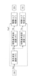
- FIG. 1 is an overall configuration diagram of a vehicle equipped with a vehicle traction control device TS according to the present invention. It is a functional block diagram for explaining an outline of traction control device TS. It is a functional block diagram for explaining drive torque control of traction control device TS.
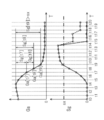
- FIG. 9 is a time-series diagram for describing processing in a decrease amount calculation block SG.
- FIG. 9 is a time-series diagram for explaining a process of reducing an integrated amount Sg. It is a time series diagram for demonstrating an effect
- the drive device YD is connected to the front wheels WHf via the drive shaft DS. That is, the vehicle is a front-wheel drive vehicle in which the front wheels WHf are used as drive wheels.
- the vehicle includes a braking operation member BP, a braking operation amount sensor BA, an acceleration operation member AP, an acceleration operation amount sensor AA, a shift operation member HP, a shift position sensor HA, a steering operation member SW, a steering angle sensor SA, and a wheel speed sensor VW.
- a yaw rate sensor YR a longitudinal acceleration sensor GX, a lateral acceleration sensor GY, a braking device YB, and a driving device YD.
- the braking operation member (for example, a brake pedal) BP is a member operated by the driver to decelerate the vehicle. By operating the braking operation member BP, the braking torque Bq for the wheel WH is adjusted, and a braking force is generated on the wheel WH.
- a brake operation amount sensor BA is provided to detect the operation amount Ba of the brake operation member (brake pedal) BP by the driver.
- a master cylinder pressure sensor PM for detecting a hydraulic pressure (master cylinder pressure) Pm in the master cylinder CM
- an operation displacement sensor for detecting an operation displacement Sp of the braking operation member BP.
- SP not shown
- an operating force sensor FP not shown
- the acceleration operation member (for example, accelerator pedal) AP is a member operated by the driver to accelerate the vehicle and run at a constant speed. By operating the acceleration operation member AP, the driving torque Tq for the wheel WH is adjusted, and a driving force is generated on the wheel WH.
- An acceleration operation amount sensor AA is provided to detect an operation amount Aa of the acceleration operation member (accelerator pedal) AP by the driver.
- an acceleration operation displacement sensor that detects an operation displacement of the acceleration operation member AP is employed as the acceleration operation amount sensor AA.
- the vehicle is provided with a shift operation member (for example, a shift lever) HP for performing a shift operation. Further, a shift position sensor HA for detecting a shift position Ha of the shift operation member HP is provided.
- a shift operation member for example, a shift lever
- a shift position sensor HA for detecting a shift position Ha of the shift operation member HP is provided.
- a steering operation member (for example, a steering wheel) SW is a member operated by a driver to turn the vehicle.
- a steering angle Sa is given to a steered wheel (for example, the front wheel WHf), a lateral force is generated on the wheel WH, and the vehicle turns.
- a steering angle sensor SA is provided to detect a rotation angle (steering angle) Sa of the steering operation member SW.
- the wheel WH is provided with a wheel speed sensor VW for detecting a wheel speed Vw which is a rotation speed of the wheel WH.
- the vehicle body includes a yaw rate sensor YR for detecting the yaw rate Yr of the vehicle, a longitudinal acceleration sensor GX for detecting an acceleration (longitudinal acceleration) Gx in the longitudinal direction of the vehicle, and an acceleration (lateral acceleration) Gy in the lateral direction of the vehicle.
- a lateral acceleration sensor GY for detecting is provided.
- the braking device YB includes a master cylinder CM, a brake caliper CP, a wheel cylinder CW, a rotating member KT, a friction material MS, a fluid unit HU, and a braking controller ECB.
- the master cylinder CM, the fluid unit HU, and the wheel cylinder CW are connected via a braking fluid path HW.
- Each wheel WH of the vehicle includes a brake caliper CP, a wheel cylinder CW, a rotating member KT, and a friction material MS.
- a rotating member (brake disc) KT is fixed to the wheel WH, and a brake caliper CP is arranged.
- the brake caliper CP is provided with a wheel cylinder CW.
- the fluid unit HU is operated when anti-skid control, traction control, vehicle stabilization control, etc. are executed.
- the brake hydraulic pressure Pw is adjusted independently of the operation of the brake operation member BP and individually for each wheel.
- the fluid unit HU includes an electric pump, a plurality of solenoid valves, and a low-pressure reservoir.
- the fluid unit HU (in particular, the electric motor of the electric pump and the solenoid valve) is controlled by the braking controller ECB.
- the braking operation amount Ba (Pm, Sp, Fp), the wheel speed Vw, the yaw rate Yr, the steering angle Sa, the longitudinal acceleration Gx, the lateral acceleration Gy, and the like are input to the controller ECB.
- anti-skid control is performed so as to suppress excessive deceleration slip (for example, wheel lock) of the wheel WH.
- traction control is executed so as to suppress excessive acceleration slip (for example, wheel spin) of the wheel WH.
- a driving force is generated by the driving device YD on driving wheels (wheels connected to the driving device YD) among the wheels WH.
- the drive device YD includes a power source EN (also referred to as a “drive source”), a transmission TM, and a drive controller ECD.
- the power source EN (for example, an internal combustion engine) is controlled by the drive controller ECD according to the acceleration operation amount Aa.
- the transmission TM (for example, an automatic transmission) is controlled by the drive controller ECD according to the shift position Ha.
- a torque converter TC is included between power source EN and transmission TM, and output Qa of power source EN is transmitted to transmission TM via torque converter TC.
- the power source EN is provided with a throttle sensor TH for detecting the throttle opening Th, an injection amount sensor FI for detecting the fuel injection amount Fi, and a rotation speed sensor NE for detecting the driving rotation speed Ne.
- the drive controller ECD calculates the acceleration operation amount Aa (actual value), the throttle opening Th (actual value), the fuel injection amount Fi (actual value), and the driving speed Ne (actual value) of the power source EN.
- Output Qa of power source EN is controlled.
- An electric motor for driving may be adopted as the power source EN. In this case, the amount of current (for example, current value) Im to the power source EN and the rotational speed Nm are detected. Then, the output Qa of the driving motor is controlled based on the acceleration operation amount Aa (actual value), the energization amount Im (actual value), and the motor speed Nm (actual value).
- the transmission TM is provided with a gear position sensor GP for detecting a gear ratio (gear position) Gp (actual value).
- the gear ratio Gp of the automatic transmission TM is controlled by the drive controller ECD based on signals (Aa, Th, Fi, Ne, Im, Nm, etc.) related to the power source EN.
- the drive controller ECD calculates and outputs the required throttle opening Ths, the fuel injection amount Fis, and the required gear ratio Gps based on the acceleration operation amount Aa.
- the required throttle opening Ths, the fuel injection amount Fis, and the required gear ratio Gps are target values of the throttle opening Th, the fuel injection amount Fi, and the gear ratio Gp.
- the actual throttle opening Th, the actual fuel injection amount Fi, and the actual gear ratio Gp are controlled so as to match the required throttle opening Ths, the required fuel injection amount Fis, and the required gear ratio Gps.
- the power source EN is an electric motor
- the required energization amount (target value) Ims is calculated based on the acceleration operation amount Aa, and control is performed so that the actual energization amount Im matches the target value Ims. You.
- the drive controller ECD and the brake controller ECB share information (computed values, sensor values, etc.) via the communication bus BS. For example, traction control, vehicle stabilization control, and the like are executed by the braking controller ECB.
- the output of the power source EN is reduced by the drive controller ECD in response to the instruction signal (target output Qt) from the brake controller ECB.
- a controller that shares information via the communication bus BS is called an “ECU (electronic control unit)”. That is, the controller ECU includes at least the drive controller ECD and the brake controller ECB.
- the outline of the traction control device TS will be described with reference to the functional block diagram of FIG.
- the traction control device TS includes “processing for controlling the power source (drive source) EN to control the drive torque Tq of the drive wheel WHf (front wheel)” and “processing for controlling the fluid unit HU to drive the drive wheel WHf.
- the traction control device TS includes a vehicle speed calculation block VX, a driving reference speed calculation block VK, a driving torque control block QT, a braking reference speed calculation block VS, and a braking torque control block BT.
- the vehicle speed Vx is calculated in the vehicle speed calculation block VX based on the wheel speed Vw.
- the vehicle speed Vx is calculated based on the wheel speed Vwr of the driven wheel WHr.
- the driven wheel WHr is a wheel to which power from the driving device YD is not transmitted, and corresponds to a rear wheel WHr in a front-wheel-drive vehicle.
- the drive reference speed calculation block VK calculates the drive reference speed Vk based on the vehicle speed Vx.
- the drive reference speed Vk is a wheel speed serving as a reference when the output Qa of the power source EN is controlled (during drive torque control).
- the predetermined speed vk is a predetermined value (constant) set in advance.
- the target output Qt is calculated based on the drive reference speed Vk and the drive wheel speed Vwf.
- the target output Qt is a target value (limit value) for limiting the actual output Qa of the power source EN. Therefore, when the actual output Qa is equal to or less than the target output Qt, the output Qa of the power source EN is not limited.
- the throttle opening Th and the fuel injection amount Fi are reduced so that the output Qa becomes equal to or less than the target output Qt. Output Qa is reduced. As a result, the drive torque Tq of WHf is reduced, and excessive acceleration slip Sw is suppressed. Details of the drive torque control block QT will be described later.
- the reference braking speed Vs is calculated based on the vehicle speed Vx.
- the braking reference speed Vs is a wheel speed serving as a reference when the braking fluid pressure Pw is controlled (during braking torque control).
- the predetermined speed vs is a predetermined value (constant) set in advance, and has a relationship of “vs> vk”.
- the fluid unit HU is controlled based on the braking reference speed Vs and the driving wheel speed Vwf. Specifically, the brake fluid pressure Pw is adjusted such that the drive wheel speed Vwf approaches and coincides with the braking reference speed Vs.
- the braking reference speed Vs is higher than the driving reference speed Vk. Therefore, in the traction control, first, the driving torque control is executed.
- the driving torque control is executed.
- the drive wheel speed Vwf does not increase or does not sufficiently decrease despite the output Qa being reduced by the drive torque control
- the acceleration slip Sw of the drive wheel WHf is rapidly reduced by the braking torque control block BT.
- the braking hydraulic pressure Pwf is increased (that is, the braking torque Bq of the drive wheel WHf is increased).
- the details of the drive torque control of the traction control device TS will be described with reference to the functional block diagram of FIG.
- the driving torque control includes a vehicle speed calculation block VX, a drive reference speed calculation block VK, a drive wheel average speed calculation block VH, a proportional / integral control block QS, a longitudinal acceleration calculation block GA, a decrease amount calculation block SG, and an adjustment processing block. It is composed of CQ.
- the vehicle speed Vx is calculated in the vehicle speed calculation block VX based on the wheel speed Vw (particularly, the wheel speed Vwr of the driven wheel WHr).
- a predetermined speed vk (for example, a constant) is added to the vehicle body speed Vx to determine a drive reference speed Vk (also simply referred to as “reference speed Vk”).
- the driving wheel average speed Vh (also simply referred to as “average speed Vh”) is calculated based on the wheel speed Vwf of the driving wheel WHf.
- the drive wheel WHf is a wheel to which power from the drive device YD is transmitted, and corresponds to the front wheel WHf in a front-wheel drive vehicle.
- the average speed Vh is an average value of the two drive wheel speeds Vwf.
- the predetermined values sz and qs are preset constants.
- the longitudinal acceleration Ga is calculated based on the vehicle speed Vx.
- the longitudinal acceleration Ga is the actual longitudinal acceleration (actual acceleration) of the vehicle (body).
- the vehicle speed Vx is time-differentiated at a predetermined calculation cycle (for example, every several milliseconds), and the longitudinal acceleration Ga is calculated.
- the longitudinal acceleration Gx detected by the longitudinal acceleration sensor GX may be employed as the longitudinal acceleration Ga.
- both the longitudinal acceleration Gx (detected value) and the longitudinal acceleration Ga (calculated value) may be used as the longitudinal acceleration Ga so as to improve the robustness.
- the integrated amount Sg is calculated based on the longitudinal acceleration Ga.
- the integrated amount Sg is a decrease amount from the peak value of the longitudinal acceleration Ga.
- the current longitudinal acceleration Ga [n] (from the previous longitudinal acceleration Ga [n ⁇ 1] (corresponding to “previous value”) ( The amount of reduction Gg [n] corresponding to “current value” is calculated.
- “n” at the end of the symbol indicates the operation cycle
- “n” indicates the current (current) operation cycle
- “n-1" indicates the immediately preceding operation cycle (previous), respectively.
- the reduction amount Gg [n] is sequentially accumulated for each calculation cycle.
- the predetermined ratio rs is a preset constant. For example, the predetermined ratio rs is set to “0%”. In this case, when the longitudinal acceleration Ga increases, the integrated value Sg is reset to “0”.
- the decrease amount calculation block SG includes a timer (time counter). The continuation of time is calculated by this timer. For the first time after the traction control is started, the continuation time is counted from the time when the longitudinal acceleration Ga decreases (the corresponding calculation cycle). The integrated value Sg is reset to “0” when a predetermined time tx has elapsed from the time when the state where the integrated value Sg is larger than the predetermined amount sx is satisfied for the first time.
- the predetermined amount sx and the predetermined time tx are preset constants.
- the required output Qs (also referred to as “required torque”) is adjusted based on the integrated amount Sg, and the target output Qt (also referred to as “target torque”) is calculated. Is done.
- the target output Qt (target torque) is a final target value of the limited torque in the drive torque control.
- Qa ⁇ Qt no limitation is performed and the actual output Qa is not reduced.
- Qa> Qt the power source EN is controlled so that the actual output Qa decreases to the target output Qt (throttle opening Th, fuel injection amount Fi, and motor power amount Im are reduced).
- the adjustment output Qg is for reducing and adjusting the required output Qs to determine the final target output Qt.
- the predetermined amount sx is a threshold value for determining whether or not the required output Qs is adjusted to be reduced or not (that is, whether to calculate the adjusted output Qg or not), and is a predetermined constant set in advance. It is.
- the adjustment output Qg is set as the predetermined torque qg.
- the predetermined torque qg is a preset constant.
- the adjustment output Qg can be determined based on at least one of the slip state sw and the duration time tg.
- the slip state sw is a value of the acceleration slip Sw at the time when “Sg> sx” is satisfied (a corresponding calculation cycle). As shown in the calculation map Zs of the blowing section, the calculation is performed such that the adjustment output Qg increases as the slip state sw increases. The fact that the slip state sw is large is based on the fact that the target output Qt should be made smaller.
- the duration tg is the time from the time when the increase of the integrated amount Sg is started to the time when “Sg> sx” is satisfied. As shown in the calculation map Zt, the adjustment output Qg is calculated so as to be smaller as the duration tg is longer.
- the long duration time tg is based on the fact that the longitudinal acceleration does not decrease so much and the acceleration slip Sw does not increase rapidly.
- the actual longitudinal acceleration Ga is calculated.
- the amount of decrease Gg of the longitudinal acceleration Ga (the amount Gg [n] reduced from the previous value Ga [n-1] in the current value Ga [n]) is calculated in each calculation cycle.
- the total of the reduction amounts Gg from the time when the longitudinal acceleration Ga exhibits the peak value and the decrease in the longitudinal acceleration Ga is started ie, the calculation cycle in which the decrease in the longitudinal acceleration Ga is determined) is the integrated amount Sg It is.
- the adjustment output Qg adjustment torque
- the target output Qt target torque
- the predetermined amount sx is a threshold value (a preset constant) for determining whether or not the adjustment output Qg is necessary.
- the adjustment for decreasing the target output Qt is ended when the increase in the longitudinal acceleration Ga is started.
- the decrease adjustment can be ended when the integrated value Sg becomes equal to or less than the predetermined amount sx.
- the decrease adjustment may be terminated when a predetermined time tx (a preset constant) has elapsed from the time when “Sg> sx” is satisfied for the first time.
- the adjustment output Qg is not immediately set to “0”, but is gradually decreased (with the time change gradient limited) toward “0”.
- the target output Qt is smoothly increased to the required output Qs so that a sudden change in the output Qa is suppressed.
- the target output Qt is greatly reduced when the longitudinal acceleration Ga continues to decrease during vehicle acceleration.
- the state where the road surface friction coefficient is high is changed.
- the case where the state has changed to a low state is appropriately determined.
- the road surface friction state is determined using not only the state quantity at the present time but also the past state quantity, the complexity of the control due to the fluctuation of the control amount of the traction control is suppressed.
- the actual output Qa is reduced to a value suitable for the road surface friction coefficient. Excessive acceleration slip Sw of the drive wheel WHf is quickly suppressed, and the convergence of the drive wheel WHf is improved. As a result, the driver's feeling of acceleration of the vehicle is improved.
- the integrated amount Sg [t9] is calculated as “Sg [t8] + Gg [t9]”.
- the target output Qt is greatly reduced (ie, sharply reduced).
- the longitudinal acceleration Ga [t15] increases from the longitudinal acceleration Ga [t14].
- rs 0%
- the integrated amount Sg [t15] is reset to “0”.
- the integrated amount Sg [t15] is determined to be “1 /” of the integrated amount Sg [t14] (see the characteristic indicated by the broken line).
- the integrated amount Sg increases.
- the integrated amount Sg decreases repeatedly.
- the longitudinal acceleration Ga increases
- the integrated amount Sg is equal to or less than the threshold value sx
- the duration of the decrease adjustment is a predetermined time tz (a preset constant)” At least one of the above is adopted.
- the “increase of the longitudinal acceleration Ga” or the “condition of“ Sg ⁇ sx ”due to the decrease of the integrated amount Sg” is satisfied, and the decrease adjustment of the target output Qt is ended.
- the adjustment output Qg is gradually reduced and the target output Qt is gradually increased so as to avoid a sudden change in the actual output Qa.
- FIG. 5 (a) shows a decreasing process when the longitudinal acceleration Ga increases.
- “Ga [u5] ⁇ Ga [u4]” so that the integrated amount Sg [u5] is calculated.
- the longitudinal acceleration Ga decreases, the integrated amount Sg increases.
- “Ga [u10] ⁇ Ga [u9]” is satisfied, and the longitudinal acceleration Ga is increased.
- FIG. 5B shows a decreasing process when the increase of the integrated amount Sg exceeds the predetermined time tx.
- the calculation of the integrated amount Sg is started and starts to increase from “0”.
- the longitudinal acceleration Ga decreases, the integrated amount Sg is sequentially increased. Since the state of “Sg ⁇ sx” is continued, the reduction of the target output Qt is not executed.
- the duration of “Sg ⁇ sx” becomes equal to or longer than tx.
- the integrated amount Sg [v17] is reset to “0”.
- the integrated amount Sg [n] is reset to “0”, and the target output Qt decreases. I can't.
- the integrated amount Sg has been increased, when it takes time to reach the predetermined amount sx, the road surface friction coefficient is not so low, and the necessity for the rapid decrease of the target output Qt is low. Unnecessary reduction of the target output Qt can be avoided by the reduction processing based on the duration of the integrated amount Sg, and the reliability of control can be improved.
- FIG. 6A shows a case where the present invention is not applied
- FIG. 6B shows a case where the present invention is applied.
- the acceleration operation amount Aa is made constant, and an instruction output Qd (constant value ta) is instructed to the power source EN by the drive controller ECD. It is assumed that the friction coefficient of the vehicle traveling path has changed from a high state to a low state.
- the command output Qd is limited by the target output Qt ( ⁇ Qd), and the output Qa of the power source EN is suppressed (reduced).
- ⁇ Qd target output
- the output Qa of the power source EN is suppressed (reduced).
- the command output Qd by the driver is limited by the target output Qt by the traction control, but since the restriction is insufficient, it takes time for the average speed Vh to converge to the drive reference speed Vk. Since the acceleration slip Sw becomes excessive and a driving force corresponding to the road surface friction coefficient cannot be obtained, the driver may feel "slack" in vehicle acceleration.
- Traction controller TS suppresses excessive acceleration slip Sw of drive wheel WHf to which output Qa of power source EN is transmitted.
- the traction control device TS includes a longitudinal acceleration calculation block GA, a decrease calculation block SG, and an adjustment processing block CQ.
- the longitudinal acceleration calculation block GA (acceleration calculation unit) calculates the longitudinal acceleration Ga at a predetermined calculation cycle. For example, in the longitudinal acceleration calculation block GA, the longitudinal acceleration Ga is calculated by differentiating the time based on the vehicle speed Vx corresponding to the wheel speed Vw. Further, based on the longitudinal acceleration Gx (detected value) detected by the longitudinal acceleration sensor GX, it is filtered to determine the longitudinal acceleration Ga.
- the decrease amount calculation block SG stores the previous longitudinal acceleration Ga [n ⁇ 1] (previous value) in the calculation cycle.
- the current longitudinal acceleration Ga [n] current value
- the amount of reduction Gg [n] of the current value Ga [n] from the previous value Ga [n-1] is calculated.
- the reduction amount Gg [n] is integrated for each calculation cycle to determine the integration amount Sg [n].
- the adjustment processing block CQ adjustment unit
- the integrated amount Sg [n] exceeds a predetermined amount sx (a predetermined threshold for determination)
- the output Qa of the power source EN is reduced.
- the adjustment output Qg determined according to the integrated amount Sg is subtracted from the required output Qs calculated based on the acceleration slip Sw, and the target output Qt is rapidly reduced.
- the drive controller ECD controls the actual output Qa to approach and match the target output Qt, so that the output Qa is sharply reduced.
- the traction control device TS Similar to the conventional control, the traction control is started at the time point x1. From time point x1, the integrated amount Sg is calculated based on the decrease amount Gg of the longitudinal acceleration Ga. In “Sg ⁇ sx”, the required output Qs is determined as the target output Qt. At the time x2 at which the longitudinal acceleration Ga continues to decrease and “Sg> sx” is satisfied, the adjustment output Qg is calculated, the adjustment output Qg is reduced from the required output Qs, and the target output Qt is reduced. At time point x2, target output Qt is sharply reduced from value tb to value tc.
- the road surface friction coefficient has changed from a high state to a low state, and the actual output Qa is reduced to a value suitable for the road surface friction coefficient. Is reduced.
- the average speed Vh (the average value of the two drive wheel speeds Vwf) quickly approaches the drive reference speed Vk. That is, the convergence of the wheel speed Vwf of the driving wheel WHf is improved, and the driving force of the driving wheel WHf can be appropriately secured according to the decrease in the road surface friction coefficient.
- the integrated amount Sg [n] is obtained by multiplying the integrated value Sg [n-1] by a predetermined ratio rs. It is reduced to a value (eg, reset to “0 (zero)”). Further, in the decrease amount calculation block SG, when the state in which the integrated amount Sg [n] is equal to or smaller than the predetermined amount sx is continued for a predetermined time tx or longer, the integrated amount Sg [n] is set to “0 (zero)”. Is reset to Thereby, the reliability of the control in reducing the target output Qt can be improved.
- the traction control device TS is applied to a front wheel drive vehicle in which the drive wheels connected to the power source EN are the front wheels WHf.
- the traction control device TS can be applied to a rear-wheel drive vehicle.
- the driving wheel is the rear wheel WHr
- the driven wheel is the front wheel WHf.
- at least one of the differential value (calculated value) of the vehicle body speed Vx and the detected longitudinal acceleration Gx (the detected value of the longitudinal acceleration sensor GX) is adopted as the longitudinal acceleration Ga.
- the traction control device TS may be applied to a four-wheel drive vehicle.
- a four-wheel drive vehicle it is preferable to use the detected longitudinal acceleration Gx as the longitudinal acceleration Ga.
- four wheels are drive wheels, it is based on the fact that all the wheels WH include the acceleration slip Sw.
Landscapes
- Engineering & Computer Science (AREA)
- Chemical & Material Sciences (AREA)
- Combustion & Propulsion (AREA)
- Mechanical Engineering (AREA)
- General Engineering & Computer Science (AREA)
- Control Of Vehicle Engines Or Engines For Specific Uses (AREA)
- Regulating Braking Force (AREA)
Abstract
トラクション制御装置は、駆動車輪の過大な加速スリップを抑制するよう、動力源の出力を制限する。トラクション制御装置は、「前後加速度を所定の演算周期で演算する加速度演算部」と、「演算周期において前回の前後加速度を前回値Ga[n-1]とし、演算周期において今回の前後加速度を今回値Ga[n]とし、前回値Ga[n-1]からの今回値Ga[n]の減少量Gg[n]を演算し、減少量Gg[n]を演算周期毎に積算して積算量Sg[n]とする減少量演算部」と、「積算量Sg[n]が所定量sxを超過した場合に、出力を減少する調整部」と、を含んで構成される。
Description
本発明は、車両のトラクション制御装置に関する。
特許文献1には、路面μの低下等による駆動輪のスリップを適切に且つ速やかに抑制することを目的に、路面μの変化速度を検出し、それが所定値より小さいとき、つまり路面μが所定速度以上で高い状態から低い状態に移行したときには、駆動輪スリップ量に乗じられるゲインを補正する補正係数を大きくして、要求トルクを小さくし、エンジントルクを減少して駆動輪のスリップを抑制することが記載されている。特許文献1では、路面μは、「μ=K1・(XG2+YG2)1/2 XGは前後加速度、YGは横加速度、K1は定数」にて演算される。
特許文献2には、モータトラクション制御時、低μ路でのハンチング防止と高μ路での振動防止の両立を図るため、路面摩擦係数相当値を推定する路面摩擦係数相当値推定手段を設け、モータトラクション制御時、前記路面摩擦係数相当値が低摩擦係数側では算出されたモータトルク制限値に対するモータトルク指令値の位相遅れを小さくし、前記路面摩擦係数相当値が高摩擦係数側では算出されたモータトルク制限値に対するモータトルク指令値の位相遅れを大きくすることが記載されている。
更に、特許文献2には、路面μの変化に関して、「モータ角加速度を検出し、この検出値が第1設定値以下の負の角加速度を示す場合、低μ路から高μ路へ路面摩擦係数が急変するμジャンプと判断する。検出値が第2設定値以上の正の角加速度を示す場合、高μ路から低μ路へ路面摩擦係数が急変するμジャンプと判断する」ことが記載されている。
ところで、車両が加速する場合(特に、発進時)に、路面の摩擦係数が高い状態から低い状態に変化すると、車両の前後加速度が十分に得られず、運転者に「もたつき感」を与える場合がある。路面の摩擦係数は、それが一定と思われても、微視的には不均一である。このため、従来技術の様に、前後、横加速度、或いは、モータ角加速度等の状態量に基づいて、逐次、判定を行う方法では、これらの状態量の変動に起因して、トラクション制御の制御量の調整が煩雑に繰り返されることが生じ得る。従って、路面の摩擦係数が高い状態から低い状態に変化したことが適切に判定され、安定、且つ、ロバストなトラクション制御が実行され得るものが望まれている。
本発明の目的は、車両のトラクション制御装置において、路面の摩擦係数が高い状態から低い状態に変化している場合が好適に判定され、安定したトラクション制御が実行され、加速感が向上され得るものを提供することである。
本発明に係る車両のトラクション制御装置(TS)は、車両の動力源(EN)の出力(Qa)が伝達される駆動車輪(WHf、WHr)の過大な加速スリップ(Sw)を抑制するよう、前記出力(Qa)を制限する。車両のトラクション制御装置(TS)は、「前記車両の前後加速度(Ga)を所定の演算周期で演算する加速度演算部(GA)」と、「前記演算周期において前回の前記前後加速度(Ga)を前回値(Ga[n-1])とし、前記演算周期において今回の前記前後加速度(Ga)を今回値(Ga[n])とし、前記前回値(Ga[n-1])からの前記今回値(Ga[n])の減少量(Gg[n])を演算し、前記減少量(Gg[n])を前記演算周期毎に積算して積算量(Sg[n])とする減少量演算部(SG)」と、「前記積算量(Sg[n])が所定量(sx)を超過した場合に、前記出力(Qt、Qa)を減少する調整部(CQ)」と、を含んで構成される。
上記構成によれば、積算量Sgに基づいて、路面の摩擦係数が高い状態から低い状態に変化している場合が適切に判定され、実際の出力Qaが路面摩擦係数に適した値にまで減少される。駆動車輪WHf、WHrの過大な加速スリップSwが迅速に抑制され、駆動車輪WHf、WHrの収束性が向上される。結果、運転者に対する「もたつき感」が解消され、車両加速感が向上される。
<構成部材等の記号、及び、記号末尾の添字>
以下の説明において、「ECU」等の如く、同一記号を付された構成部材、演算処理、信号、特性、及び、値は、同一機能のものである。各車輪に係る記号の末尾に付された添字「f」、「r」は、「f」は前輪に係るもの、「r」は後輪に係るものを示す包括記号である。例えば、車輪速度センサにおいて、前輪車輪速度センサVWf、及び、後輪車輪速度センサVWrと表記される。更に、記号末尾の添字「f」、「r」は省略され得る。添字「f」、「r」が省略された場合には、各記号は、その総称を表す。例えば、「VW」は、各車輪速度センサを表す。
以下の説明において、「ECU」等の如く、同一記号を付された構成部材、演算処理、信号、特性、及び、値は、同一機能のものである。各車輪に係る記号の末尾に付された添字「f」、「r」は、「f」は前輪に係るもの、「r」は後輪に係るものを示す包括記号である。例えば、車輪速度センサにおいて、前輪車輪速度センサVWf、及び、後輪車輪速度センサVWrと表記される。更に、記号末尾の添字「f」、「r」は省略され得る。添字「f」、「r」が省略された場合には、各記号は、その総称を表す。例えば、「VW」は、各車輪速度センサを表す。
<本発明に係るトラクション制御装置TSを備えた車両の全体構成>
図1の全体構成図を参照して、本発明に係る車両のトラクション制御装置TSを搭載した車両について説明する。車両では、駆動装置YDが、駆動シャフトDSを介して、前輪WHfに接続される。つまり、前輪WHfが駆動車輪とされる前輪駆動の車両である。
図1の全体構成図を参照して、本発明に係る車両のトラクション制御装置TSを搭載した車両について説明する。車両では、駆動装置YDが、駆動シャフトDSを介して、前輪WHfに接続される。つまり、前輪WHfが駆動車輪とされる前輪駆動の車両である。
車両には、制動操作部材BP、制動操作量センサBA、加速操作部材AP、加速操作量センサAA、変速操作部材HP、シフト位置センサHA、操舵操作部材SW、操舵角センサSA、車輪速度センサVW、ヨーレイトセンサYR、前後加速度センサGX、横加速度センサGY、制動装置YB、及び、駆動装置YDが備えられる。
制動操作部材(例えば、ブレーキペダル)BPは、運転者が車両を減速させるために操作する部材である。制動操作部材BPが操作されることによって、車輪WHに対する制動トルクBqが調整され、車輪WHに制動力が発生される。
運転者による制動操作部材(ブレーキペダル)BPの操作量Baを検出するよう、制動操作量センサBAが設けられる。具体的には、制動操作量センサBAとして、マスタシリンダCM内の液圧(マスタシリンダ液圧)Pmを検出するマスタシリンダ液圧センサPM、制動操作部材BPの操作変位Spを検出する操作変位センサSP(図示せず)、及び、制動操作部材BPの操作力Fpを検出する操作力センサFP(図示せず)のうちの少なくとも1つが採用される。
加速操作部材(例えば、アクセルペダル)APは、運転者が車両を加速し、定速走行するために操作する部材である。加速操作部材APが操作されることによって、車輪WHに対する駆動トルクTqが調整され、車輪WHに駆動力が発生される。運転者による加速操作部材(アクセルペダル)APの操作量Aaを検出するよう、加速操作量センサAAが設けられる。例えば、加速操作量センサAAとして、加速操作部材APの操作変位を検出する加速操作変位センサが採用される。
車両には、変速操作を行うための変速操作部材(例えば、シフトレバー)HPが備えられる。そして、変速操作部材HPのシフト位置Haを検出するシフト位置センサHAが設けられる。
操舵操作部材(例えば、ステアリングホイール)SWは、運転者が車両を旋回させるために操作する部材である。操舵操作部材SWが操作されることによって、操向車輪(例えば、前輪WHf)に操舵角Saが付与され、車輪WHに横力が発生され、車両が旋回される。操舵操作部材SWの回転角度(操舵角)Saを検出するよう、操舵角センサSAが設けられる。
車輪WHには、車輪WHの回転速度である車輪速度Vwを検出する車輪速度センサVWが備えられる。車両の車体には、車両のヨーレイトYrを検出するヨーレイトセンサYR、車両の前後方向における加速度(前後加速度)Gxを検出する前後加速度センサGX、及び、車両の横方向における加速度(横加速度)Gyを検出する横加速度センサGYが設けられる。
制動装置YBによって、車輪WHに制動力が発生される。制動装置YBは、マスタシリンダCM、ブレーキキャリパCP、ホイールシリンダCW、回転部材KT、摩擦材MS、流体ユニットHU、及び、制動コントローラECBにて構成される。マスタシリンダCM、流体ユニットHU、及び、ホイールシリンダCWは、制動流体路HWを介して接続される。
通常の制動時には、流体ユニットHUは作動されず、制動操作部材BPの操作に応じて、マスタシリンダCMから、制動液BFが、ホイールシリンダCWに圧送される。車両の各車輪WHには、ブレーキキャリパCP、ホイールシリンダCW、回転部材KT、及び、摩擦材MSが備えられる。具体的には、車輪WHには、回転部材(ブレーキディスク)KTが固定され、ブレーキキャリパCPが配置されている。ブレーキキャリパCPには、ホイールシリンダCWが設けられる。ホイールシリンダCW内の液圧(制動液圧)Pwが調整されることによって、車輪WHに制動トルクBq(結果、制動力)が発生される。
流体ユニットHUは、アンチスキッド制御、トラクション制御、車両安定化制御等が実行される場合に作動される。流体ユニットHUの作動によって、制動液圧Pwは、制動操作部材BPの操作とは独立に、且つ、各輪個別に調整される。これにより、各車輪WHの前後力(制・駆動力)が、独立、且つ、個別に制御される。流体ユニットHUは、電動ポンプ、複数の電磁弁、及び、低圧リザーバを含んで構成される。
制動コントローラECBによって、流体ユニットHU(特に、電動ポンプの電気モータ、及び、電磁弁)が制御される。コントローラECBには、制動操作量Ba(Pm、Sp、Fp)、車輪速度Vw、ヨーレイトYr、操舵角Sa、前後加速度Gx、横加速度Gy、等が入力される。コントローラECBでは、例えば、車輪WHの過度の減速スリップ(例えば、車輪ロック)を抑制するよう、アンチスキッド制御が実行される。また、車輪WHの過度の加速スリップ(例えば、車輪スピン)を抑制するよう、トラクション制御が実行される。
駆動装置YDによって、各車輪WHのうちの駆動車輪(駆動装置YDに接続された車輪)に駆動力が発生される。駆動装置YDは、動力源EN(「駆動源」ともいう)、変速機TM、及び、駆動コントローラECDを含んで構成される。動力源EN(例えば、内燃機関)は、加速操作量Aaに応じて、駆動コントローラECDによって制御される。また、変速機TM(例えば、自動変速機)は、シフト位置Haに応じて、駆動コントローラECDによって制御される。動力源ENと変速機TMとの間には、トルクコンバータTCが含まれ、動力源ENの出力Qaは、トルクコンバータTCを介して、変速機TMに伝達される。
動力源ENには、スロットル開度Thを検出するスロットルセンサTH、燃料噴射量Fiを検出する噴射量センサFI、及び、駆動回転数Neを検出る回転数センサNEが設けられる。駆動コントローラECDによって、加速操作量Aa(実際値)、スロットル開度Th(実際値)、燃料噴射量Fi(実際値)、及び、動力源ENの駆動回転数Ne(実際値)に基づいて、動力源ENの出力Qaが制御される。動力源ENとして、駆動用の電気モータが採用され得る。この場合、動力源ENへの通電量(例えば、電流値)Im、及び、回転数Nmが検出される。そして、加速操作量Aa(実際値)、通電量Im(実際値)、及び、モータ回転数Nm(実際値)に基づいて、駆動用モータの出力Qaが制御される。
変速機TMには、変速比(ギヤ位置)Gp(実際値)を検出するためのギヤ位置センサGPが設けられる。動力源ENに係る信号(Aa、Th、Fi、Ne、Im、Nm、等)に基づいて、駆動コントローラECDによって、自動変速機TMの変速比Gpが制御される。
駆動コントローラECDによって、加速操作量Aaに基づいて、要求スロットル開度Ths、燃料噴射量Fis、及び、要求変速比Gpsが演算され、出力される。要求スロットル開度Ths、燃料噴射量Fis、及び、要求変速比Gpsは、スロットル開度Th、燃料噴射量Fi、及び、変速比Gpの目標値である。実スロットル開度Th、実燃料噴射量Fi、及び、実変速比Gpが、要求スロットル開度Ths、要求燃料噴射量Fis、及び、要求変速比Gpsに一致するよう制御される。なお、動力源ENが電気モータである場合には、加速操作量Aaに基づいて要求通電量(目標値)Imsが演算され、この目標値Imsに、実際の通電量Imが一致するよう制御される。
駆動コントローラECDと制動コントローラECBとは、通信バスBSを介して情報(演算値、センサ値等)が共有されている。例えば、制動コントローラECBにて、トラクション制御、車両安定化制御等が実行される。制動コントローラECBからの指示信号(目標出力Qt)に応じて、駆動コントローラECDによって動力源ENの出力が減少される。通信バスBSを通して情報共有されるコントローラが、「ECU(電子制御ユニット)」と称呼される。つまり、コントローラECUは、少なくとも、駆動コントローラECD、及び、制動コントローラECBを含んで構成される。
<トラクション制御装置TSの概要>
図2の機能ブロック図を参照して、トラクション制御装置TSの概要について説明する。トラクション制御装置TSには、「動力源(駆動源)ENを制御して、駆動車輪WHf(前輪)の駆動トルクTqを制御する処理」、及び、「流体ユニットHUを制御して、駆動車輪WHfの制動トルクBqを制御する処理」にて構成される。トラクション制御装置TSには、車体速度演算ブロックVX、駆動基準速度演算ブロックVK、駆動トルク制御ブロックQT、制動基準速度演算ブロックVS、及び、制動トルク制御ブロックBTが含まれる。
図2の機能ブロック図を参照して、トラクション制御装置TSの概要について説明する。トラクション制御装置TSには、「動力源(駆動源)ENを制御して、駆動車輪WHf(前輪)の駆動トルクTqを制御する処理」、及び、「流体ユニットHUを制御して、駆動車輪WHfの制動トルクBqを制御する処理」にて構成される。トラクション制御装置TSには、車体速度演算ブロックVX、駆動基準速度演算ブロックVK、駆動トルク制御ブロックQT、制動基準速度演算ブロックVS、及び、制動トルク制御ブロックBTが含まれる。
車体速度演算ブロックVXにて、車輪速度Vwに基づいて、車体速度Vxが演算される。例えば、従動車輪WHrの車輪速度Vwrに基づいて、車体速度Vxが演算される。従動車輪WHrは、駆動装置YDからの動力が伝達されない車輪であり、前輪駆動の車両では、後輪WHrが該当する。
駆動基準速度演算ブロックVKにて、車体速度Vxに基づいて、駆動基準速度Vkが演算される。駆動基準速度Vkは、動力源ENの出力Qaが制御される場合(駆動トルク制御時)の基準となる車輪速度である。例えば、車体速度Vxに所定速度vkが加算されて、基準速度Vkが決定される(即ち、「Vk=Vx+vk」)。ここで、所定速度vkは、予め設定された所定値(定数)である。
駆動トルク制御ブロックQTにて、駆動基準速度Vk、及び、駆動車輪速度Vwfに基づいて、目標出力Qtが演算される。目標出力Qtは、動力源ENの実出力Qaを制限するための目標値(制限値)である。従って、実際の出力Qaが、目標出力Qt以下の場合には、動力源ENの出力Qaは制限されない。一方、実出力Qaが、目標出力Qtよりも大きい場合には、出力Qaが目標出力Qt以下になるよう、スロットル開度Th、燃料噴射量Fi(又は、モータ通電量Im)が低減され、実際の出力Qaが減少される。結果、WHfの駆動トルクTqが減少され、過大な加速スリップSwが抑制される。駆動トルク制御ブロックQTの詳細については後述する。
制動基準速度演算ブロックVSにて、車体速度Vxに基づいて、制動基準速度Vsが演算される。制動基準速度Vsは、制動液圧Pwが制御される場合(制動トルク制御時)の基準となる車輪速度である。例えば、車体速度Vxに所定速度vsが加算されて、基準速度Vsが決定される(即ち、「Vs=Vx+vs」)。ここで、所定速度vsは、予め設定された所定値(定数)であり、「vs>vk」の関係にある。
制動トルク制御ブロックBTにて、制動基準速度Vs、及び、駆動車輪速度Vwfに基づいて、流体ユニットHUが制御される。具体的には、駆動車輪速度Vwfが、制動基準速度Vsに近づき、一致するよう、制動液圧Pwが調整される。なお、所定速度vsは、所定速度vkよりも大きい値に設定されるため、制動基準速度Vsは、駆動基準速度Vkよりも大きい。このため、トラクション制御では、先ず、駆動トルク制御が実行される。駆動トルク制御によって出力Qaが減少されたにもかかわらず、駆動車輪速度Vwfが増加、又は、十分に減少しない場合に、制動トルク制御ブロックBTによって、駆動車輪WHfの加速スリップSwが速やかに減少するよう、制動液圧Pwfが増加される(即ち、駆動車輪WHfの制動トルクBqが増加される)。
<トラクション制御装置TSの駆動トルク制御>
図3の機能ブロック図を参照して、トラクション制御装置TSの駆動トルク制御の詳細について説明する。駆動トルク制御によって、駆動車輪WHf(出力Qaが伝達される車輪)の過大な加速スリップSwを抑制するよう、動力源ENの出力(動力)Qaが制限され、駆動トルクTqが減少される。駆動トルク制御は、車体速度演算ブロックVX、駆動基準速度演算ブロックVK、駆動輪平均速度演算ブロックVH、比例・積分制御ブロックQS、前後加速度演算ブロックGA、減少量演算ブロックSG、及び、調整処理ブロックCQにて構成される。
図3の機能ブロック図を参照して、トラクション制御装置TSの駆動トルク制御の詳細について説明する。駆動トルク制御によって、駆動車輪WHf(出力Qaが伝達される車輪)の過大な加速スリップSwを抑制するよう、動力源ENの出力(動力)Qaが制限され、駆動トルクTqが減少される。駆動トルク制御は、車体速度演算ブロックVX、駆動基準速度演算ブロックVK、駆動輪平均速度演算ブロックVH、比例・積分制御ブロックQS、前後加速度演算ブロックGA、減少量演算ブロックSG、及び、調整処理ブロックCQにて構成される。
車体速度演算ブロックVXにて、車輪速度Vw(特に、従動車輪WHrの車輪速度Vwr)に基づいて、車体速度Vxが演算される。駆動基準速度演算ブロックVKでは、車体速度Vxに所定速度vk(例えば、定数)が加算されて、駆動基準速度Vk(単に、「基準速度Vk」ともいう)が決定される。
駆動輪平均速度演算ブロックVHにて、駆動車輪WHfの車輪速度Vwfに基づいて、駆動輪平均速度Vh(単に、「平均速度Vh」ともいう)が演算される。駆動車輪WHfは、駆動装置YDからの動力が伝達される車輪であり、前輪駆動の車両では、前輪WHfが相当する。平均速度Vhは、2つの駆動車輪速度Vwfの平均値である。基準速度Vkと平均速度Vhに基づいて、加速スリップSwが演算される。具体的には、平均速度Vhから基準速度Vkが減算されて、加速スリップSwが決定される(即ち、「Sw=Vh-Vk」)。
比例・積分制御ブロックQSでは、加速スリップSwに基づいて、比例・積分制御が実行される。具体的には、加速スリップSwが所定値sz以上になると、トラクション制御の実行が開始される。そして、加速スリップSwに比例ゲインKpが乗算される(即ち、「Kp×Sw」)。また、加速スリップSwの時間積分値に積分ゲインKiが乗算される(即ち、「Ki×∫Sw」)。更に、これらが加算されて、要求出力Qsが演算される(即ち、「Qs=Kp×Sw+Ki×∫Sw」)。要求出力Qsは、実際の出力Qaを制限するための目標値(制限値)である。なお、トラクション制御の実行は、要求出力Qsが所定値qs以上になった場合に開始されてもよい。所定値sz、qsは予め設定された定数である。
加速度演算ブロックGA(「加速度演算部」に相当)では、車体速度Vxに基づいて、前後加速度Gaが演算される。前後加速度Gaは、車両(車体)の実際の前後加速度(実加速度)である。具体的には、所定の演算周期(例えば、数ミリ秒毎)で、車体速度Vxが時間微分されて、前後加速度Gaが演算される。また、前後加速度Gaとして、前後加速度センサGXによって検出された前後加速度Gxが採用されてもよい。更に、ロバスト性を向上するよう、前後加速度度Gx(検出値)、及び、前後加速度Ga(演算値)の両方が、前後加速度Gaとして用いられてもよい。
減少量演算ブロックSG(「減少量演算部」に相当)では、前後加速度Gaに基づいて、積算量Sgが演算される。積算量Sgは、前後加速度Gaのピーク値からの減少量である。具体的には、減少量演算ブロックSGでは、コントローラECUでの演算周期において、前回の前後加速度Ga[n-1](「前回値」に相当)からの、今回の前後加速度Ga[n](「今回値」に相当)の減少量Gg[n]が演算される。ここで、記号末尾の「n」は演算周期を表記するもので、「n」が現時点(今回)の演算周期、「n-1」が現時点から1つ前の演算周期(前回)を、夫々表す。
減少量演算ブロックSGでは、演算周期毎に、順次、減少量Gg[n]が積算されていく。今回の演算周期「n」までに、積算された減少量ΣGg[n]が、「積算量Sg[n]」と称呼される(即ち、「Sg[n]=ΣGg[n]」)。つまり、前回の演算周期「n-1」までの積算量Sg[n-1]に今回の減少量Gg[n]が加算されて、今回の積算量Sg[n]が決定される。
また、減少量演算ブロックSGでは、前回の前後加速度(前回値)Ga[n-1]から、今回の前後加速度(今回値)Ga[n]が増加した場合には、今回の積算量Sg[n]が、前回の積算量Sg[n-1]の所定割合rsに減少される(即ち、「Sg[n]=rs×Sg[n-1]」)。ここで、所定割合rsは、予め設定された定数である。例えば、所定割合rsは、「0%」に設定される。この場合、前後加速度Gaが増加した時点で、積算値Sgは、「0」にリセットされる。
加えて、減少量演算ブロックSGには、タイマ(時間カウンタ)が含まれている。このタイマによって、時間の継続状態が演算される。継続時間は、トラクション制御が開始された後に、初めて、前後加速度Gaが減少した時点(該当する演算周期)を起点にカウントされる。そして、積算値Sgが所定量sxよりも大きい状態が初めて満足された時点から、所定時間txが経過した時点で、積算値Sgは、「0」にリセットされる。ここで、所定量sx、及び、所定時間txは、予め設定された定数である。
調整処理ブロックCQ(「調整部」に相当)にて、積算量Sgに基づいて、要求出力Qs(「要求トルク」ともいう)が調整され、目標出力Qt(「目標トルク」ともいう)が演算される。目標出力Qt(目標トルク)は、駆動トルク制御における、最終的な制限トルクの目標値である。「Qa≦Qt」の場合には、制限は行われず、実出力Qaは減少されない。「Qa>Qt」の場合には、実出力Qaが目標出力Qtにまで減少するよう、動力源ENが制御される(スロットル開度Th、燃料噴射量Fi、モータ通電量Imの低減)。
具体的には、調整処理ブロックCQでは、積算量Sg[n]が所定量sxを超過した場合に、要求出力Qsが、調整出力Qg(「調整トルク」ともいう)だけ減少されて、目標出力Qtが決定される(即ち、「Qt=Qs-Qg」)。調整出力Qgは、要求出力Qsを減少調整して、最終の目標出力Qtを決定するためのものである。所定量sxは、「要求出力Qsを減少調整するか、否か(即ち、調整出力Qgを演算するか、否か)」を判定するためのしきい値であり、予め設定された所定の定数である。
例えば、調整出力Qgは、所定トルクqgとして設定される。所定トルクqgは、予め設定された定数である。また、調整出力Qgは、スリップ状態sw、及び、継続時間tgのうちの少なくとも1つに基づいて決定され得る。スリップ状態swは、「Sg>sx」が満足された時点(該当する演算周期)における加速スリップSwの値である。吹き出し部の演算マップZsに示す様に、スリップ状態swの増加に伴って、調整出力Qgが大きくなるように演算される。スリップ状態swが大であることは、目標出力Qtがより小さくされるべきであることに基づく。
継続時間tgは、積算量Sgの増加が開始された時点から、「Sg>sx」が満足される時点までの時間である。調整出力Qgは、演算マップZtに示す様に、継続時間tgが長いほど、小さくなるように演算される。継続時間tgが長いということは、前後加速度の減少が然程大きくなく、加速スリップSwが急速には増加していないことに基づく。
トラクション制御装置TSでは、実際の前後加速度Gaが演算される。そして、演算周期のたびに、前後加速度Gaの減少量Gg(今回値Ga[n]において、前回値Ga[n-1]から減少した量Gg[n])が演算される。この減少量Ggは、順次、積算されて、積算量Sg(=ΣGg)として決定される。換言すれば、前後加速度Gaがピーク値を呈し、前後加速度Gaの減少が開始された時点(即ち、前後加速度Gaの減少が判定された演算周期)からの減少量Ggの合計が、積算量Sgである。出力調整処理においては、積算量Sgが、所定量sx以下である場合には、要求出力Qsは調整されない(即ち、「Qt=Qs」)。一方、積算量Sgが所定量sxよりも大きくなった時点で、要求出力Qs(要求トルク)から、調整出力Qg(調整トルク)分が減少されて、目標出力Qt(目標トルク)が急減される(即ち、「Qt=Qs-Qg」)。所定量sxは、調整出力Qgの要否を判定するためのしきい値(予め設定された定数)である。
目標出力Qtの減少調整は、前後加速度Gaの増加が開始された時点で終了される。或いは、減少調整は、積算値Sgが所定量sx以下となった時点で終了され得る。更に、減少調整は、「Sg>sx」が初めて満足された時点から、所定時間tx(予め設定された定数)が経過した時点で終了されてもよい。減少調整の終了時には、調整出力Qgは、直ちに「0」にされるのではなく、徐々に(時間変化勾配に制限が設けられて)、「0」に向けて減少される。出力Qaの急変が抑制されるよう、目標出力Qtが、滑らかに要求出力Qsにまで増加される。
トラクション制御装置TSでは、車両加速において、前後加速度Gaの減少が継続されている場合に、目標出力Qtが大幅減少される。つまり、従来技術の様に演算周期毎に決定される状態量ではなく、或る程度の演算周期に亘る状態量に応じて決定された積算量Sgに基づいて、路面の摩擦係数が高い状態から低い状態に変化している場合が適切に判定される。換言すれば、現時点の状態量のみならず、過去の状態量が利用されて路面摩擦状態が判定されるため、トラクション制御の制御量変動に起因する、制御の煩雑さが抑制される。そして、判定結果に基づいて、実出力Qaが路面摩擦係数に適した値にまで減少される。駆動車輪WHfの過大な加速スリップSwが迅速に抑制され、駆動車輪WHfの収束性が向上される。結果、運転者に対する、車両の加速感が向上される。
<減少量演算ブロックSGでの処理>
図4の時系列線図を参照して、減少量演算ブロックSG(減少量演算部)での処理について説明する。各種記号末尾の括弧内の記号は、それがどの時点(該当する演算周期)のものであるかを示す。例えば、「Ga[t7]」は、時点t7における前後加速度Gaを表す。
図4の時系列線図を参照して、減少量演算ブロックSG(減少量演算部)での処理について説明する。各種記号末尾の括弧内の記号は、それがどの時点(該当する演算周期)のものであるかを示す。例えば、「Ga[t7]」は、時点t7における前後加速度Gaを表す。
時点t4までは、前後加速度Gaは、徐々に増加している。このため、「Gg=0」に演算され、「Sg=0」である。時点t5にて、前後加速度Ga[t5]は、前後加速度Ga[t4]から減少する。従って、時点t5には、「Gg[t5]=Ga[t5]-Ga[t4]」が演算される。時点t5では、「Sg[t5]=0」であるため、「Sg[t5]=Gg[t5]」が演算される。
時点t6にて、前後加速度Ga[t6]は、前後加速度Ga[t5]から減少する。時点t5には、「Gg[t6]=Ga[t6]-Ga[t5]」が演算される。時点t6では、「Sg[t5]=Gg[t5]」であるため、「Sg[t6]=Sg[t5]+Gg[t6]」が演算される。
同様の演算が、演算周期毎に繰り返される。つまり、前回の前後加速度Ga[n-1]からの、今回の前後加速度Ga[n]の減少量Gg[n]が演算される。そして、前回までの積算量Sg[n-1]に今回の減少量Gg[n]が加算されて、今回の積算量Sg[n]が決定される。時点t8にて、積算量Sg[t8]が、「Sg[t7]+Gg[t8]」に演算される。時点t8までは、積算量Sgが所定量sx以下であるため、要求出力Qsの調整は実行されず、要求出力Qsが、そのまま、目標出力Qtとして決定される(即ち、「Qg=0、Qt=Qs」)。
時点t9にて、積算量Sg[t9]が、「Sg[t8]+Gg[t9]」に演算される。時点t9にて、積算量Sgが所定量sxを超過するため、要求出力Qsから調整出力Qgが減少され、目標出力Qtが決定される(即ち、「Qt=Qs-Qg」)。これにより、目標出力Qtが大幅に減少(即ち、急減)される。前後加速度Gaが減少を続ける場合、「Sg>sx」の状態が維持されるため、「Qt=Qs-Qg」の状態(減少調整)が継続される。
時点t15にて、前後加速度Ga[t15]が、前後加速度Ga[t14]よりも増加する。この場合、積算量Sg[t15]は、所定割合rsに減少される(即ち、Sg[t15]=rs×Sg[t14])。例えば、「rs=0%」に設定されている場合には、積算量Sg[t15]は、リセットされ、「0」にされる。また、「rs=50%」に設定されている場合には、積算量Sg[t15]は、積算量Sg[t14]の「1/2」に決定される(破線で示す特性を参照)。その後、前後加速度Gaが減少すると、積算量Sgは増加されるが、前後加速度Gaが増加すると、積算量Sgの減少が繰り返される。
目標出力Qtの減少調整の終了条件として、「前後加速度Gaが増加」、「積算量Sgがしきい値sx以下」、及び、「減少調整の継続時間が所定時間tz(予め設定された定数)以上」のうちの少なくとも1つが採用される。時点t15にて、「前後加速度Gaの増加」、又は、「積算量Sgの減少による「Sg≦sx」の条件」が満足され、目標出力Qtの減少調整は終了される。出力調整が終了される場合には、実出力Qaが急激に変化されることを回避するよう、調整出力Qgが徐々に減少され、目標出力Qtが緩やかに増加される。
<積算量Sgの減少処理>
図5の時系列線図を参照して、積算量Sgの減少処理について説明する。ここで、所定比率rsは、「0%」に設定されている。
図5の時系列線図を参照して、積算量Sgの減少処理について説明する。ここで、所定比率rsは、「0%」に設定されている。
図5(a)は、前後加速度Gaが増加した場合についての減少処理を示している。時点u4までは、前後加速度Gaが増加するため、「Sg=0」である。時点u5にて、「Ga[u5]<Ga[u4]」となるため、積算量Sg[u5]が演算される。その後、時点u9までは、前後加速度Gaが減少するため、積算量Sgが増加する。しかし、「Sg≦sx」であるため、「Qt=Qs」が決定される。時点u10にて、「Ga[u10]≧Ga[u9]」となり、前後加速度Gaが増加される。今回の前後加速度Ga[n]が、前回の前後加速度Ga[n-1]以上となる場合には、今回の積算量Sg[n]は、前回の積算量Sg[n-1]に所定割合rsを乗じた値(=rs×Sg[n-1])に減少される。結果、積算量Sg[u10]は、「rs=0%」であるため、「0」にリセットされる。時点u12にて、前後加速度Gaが再び減少される。これに伴い、積算量Sgが「0」から増加される。前後加速度Gaが減少を継続する場合に限って、目標出力Qtの減少が行われるため、制御の信頼性が向上され得る。
図5(b)は、積算量Sgの増加が所定時間txを超えた場合の減少処理を示している。時点v5にて、積算量Sgの演算が開始され、「0」から増加され始める。前後加速度Gaの減少に従って、積算量Sgは、順次、増加されていく。「Sg≦sx」の状態が継続されるため、目標出力Qtの減少は実行されない。時点v17にて、「Sg≦sx」の継続時間がtx以上となる。このとき、積算量Sg[v17]は、「0」にリセットされる。つまり、積算量Sg[n]が所定量sx以下である状態が所定時間tx以上に亘って継続した場合に、積算量Sg[n]が「0」にリセットされ、目標出力Qtの減少は行われない。積算量Sgは増加されているが、所定量sxに到達するのに時間を要する場合は、路面摩擦係数が、然程低くはなく、目標出力Qtの急減の必要性は低い。積算量Sgの継続時間に基づく減少処理により、目標出力Qtの不必要な減少が回避され、制御の信頼性が向上され得る。
<作用・効果>
図6の時系列線図を参照して、本発明に係るトラクション制御装置TSの作用・効果について説明する。図6(a)が本発明を適用しない場合、図6(b)が本発明を適用した場合を示している。加速操作量Aaが一定にされ、駆動コントローラECDにて、動力源ENに指示出力Qd(一定値ta)が指示されている。車両走行路の摩擦係数が、高い状態から低い状態に変化した状況が想定されている。トラクション制御では、指示出力Qdが目標出力Qt(<Qd)によって制限され、動力源ENの出力Qaが抑制(低減)される。これにより、車輪WHの過剰な加速スリップ(極端な場合が車輪スピン)が抑制される。
図6の時系列線図を参照して、本発明に係るトラクション制御装置TSの作用・効果について説明する。図6(a)が本発明を適用しない場合、図6(b)が本発明を適用した場合を示している。加速操作量Aaが一定にされ、駆動コントローラECDにて、動力源ENに指示出力Qd(一定値ta)が指示されている。車両走行路の摩擦係数が、高い状態から低い状態に変化した状況が想定されている。トラクション制御では、指示出力Qdが目標出力Qt(<Qd)によって制限され、動力源ENの出力Qaが抑制(低減)される。これにより、車輪WHの過剰な加速スリップ(極端な場合が車輪スピン)が抑制される。
先ず、図6(a)を参照して、本発明が適用されない従来のトラクション制御について説明する。時点x1までは、トラクション制御は開始されていないため、目標出力Qtは演算されていない。時点x1の直前で、路面摩擦係数が低下した。このため、時点x1にて、駆動車輪WHfの加速スリップSw(=Vh-Vk)が増加し、トラクション制御のしきい値に達し、駆動トルク制御が開始される。そして、加速スリップSwに基づく比例・積分制御が実行され、要求出力Qsが演算される。従来制御では、積算量Sgは演算されないため、要求出力Qsによる目標出力Qtの減少は行われず、「Qt=Qs」が決定される。運転者による指示出力Qdが、トラクション制御による目標出力Qtによって制限されるが、その制限が不十分であるため、平均速度Vhが駆動基準速度Vkに収束するために時間を要する。加速スリップSwが過大となり、路面摩擦係数に応じた駆動力が得られないため、運転者は、車両加速における「もたつき」を感じ得る。
次に、本発明に係るトラクション制御装置TSについて説明する。トラクション制御装置TSによって、動力源ENの出力Qaが伝達される駆動車輪WHfの過大な加速スリップSwが抑制される。トラクション制御装置TSは、前後加速度演算ブロックGA、減少量演算ブロックSG、及び、調整処理ブロックCQを含んで構成される。前後加速度演算ブロックGA(加速度演算部)では、所定の演算周期で前後加速度Gaが演算される。例えば、前後加速度演算ブロックGAでは、車輪速度Vwに応じた車体速度Vxに基づいて、それが時間微分されて、前後加速度Gaが演算される。また、前後加速度センサGXによって検出された前後加速度Gx(検出値)に基づいて、それがフィルタ処理されて、前後加速度Gaが決定され得る。
減少量演算ブロックSG(減少量演算部)では、演算周期において前回の前後加速度Ga[n-1](前回値)が記憶される。演算周期において今回の前後加速度Ga[n](今回値)が取得される。そして、前回値Ga[n-1]からの今回値Ga[n]の減少量Gg[n]が演算される。減少量Gg[n]は、演算周期の毎に積算されて、積算量Sg[n]が決定される。調整処理ブロックCQ(調整部)では、積算量Sg[n]が所定量sx(所定の判定用しきい値)を超過した場合に、動力源ENの出力Qaが減少される。具体的には、加速スリップSwに基づいて演算された要求出力Qsから、積算量Sgに応じて決定された調整出力Qgが減じられて、目標出力Qtが急減される。駆動コントローラECDによって、実際の出力Qaが目標出力Qtに近づき、一致するよう制御されるため、出力Qaが急減される。
図6(b)を参照して、トラクション制御装置TSの作動について説明する。従来制御と同様に、時点x1にてトラクション制御が開始される。時点x1から、前後加速度Gaの減少量Ggに基づいて、積算量Sgが演算される。「Sg≦sx」では、要求出力Qsが、目標出力Qtとして決定される。前後加速度Gaの減少が継続され、「Sg>sx」が満足される時点x2にて、調整出力Qgが演算され、要求出力Qsから調整出力Qgが減少され、目標出力Qtが減少される。時点x2にて、目標出力Qtが、値tbから値tcにまで急減される。複数の演算周期に亘って積算された積算量Sgに基づいて、路面の摩擦係数が高い状態から低い状態に変化している場合が判定され、実出力Qaが路面摩擦係数に適した値にまで減少される。これにより、平均速度Vh(2つの駆動車輪速度Vwfの平均値)が、素早く、駆動基準速度Vkに近づけられる。つまり、駆動車輪WHfの車輪速度Vwfの収束性が向上され、駆動車輪WHfの駆動力が、路面摩擦係数の低下に応じて、好適に確保され得る。
減少量演算ブロックSGでは、今回値Ga[n]が前回値Ga[n-1]以上の場合には、積算量Sg[n]が積算値Sg[n-1]に所定割合rsを乗じた値に減少される(例えば、「0(ゼロ)」にリセットされる)。また、減少量演算ブロックSGでは、積算量Sg[n]が所定量sx以下である状態が所定時間tx以上に亘って継続された場合には、積算量Sg[n]が「0(ゼロ)」にリセットされる。これにより、目標出力Qtの減少における制御の信頼性が向上され得る。
<他の実施形態>
以下、他の実施形態について説明する。他の実施形態においても、上記同様の効果を奏する。上記実施形態では、トラクション制御装置TSが、動力源ENに接続される駆動車輪が前輪WHfである前輪駆動車両に適用された。トラクション制御装置TSは、後輪駆動車両にも適用され得る。この場合、駆動車輪は後輪WHrであり、従動車輪は前輪WHfである。後輪駆動車両でも、前後加速度Gaとして、車体速度Vxの微分値(演算値)、及び、検出前後加速度Gx(前後加速度センサGXの検出値)のうちの少なくとも1つが採用される。
以下、他の実施形態について説明する。他の実施形態においても、上記同様の効果を奏する。上記実施形態では、トラクション制御装置TSが、動力源ENに接続される駆動車輪が前輪WHfである前輪駆動車両に適用された。トラクション制御装置TSは、後輪駆動車両にも適用され得る。この場合、駆動車輪は後輪WHrであり、従動車輪は前輪WHfである。後輪駆動車両でも、前後加速度Gaとして、車体速度Vxの微分値(演算値)、及び、検出前後加速度Gx(前後加速度センサGXの検出値)のうちの少なくとも1つが採用される。
トラクション制御装置TSは、4輪駆動車両に適用されてもよい。4輪駆動車両では、前後加速度Gaとして、検出前後加速度Gxが採用されることが好適である。4つの車輪が駆動車輪である場合には、全ての車輪WHに加速スリップSwが含まれることに基づく。
Claims (4)
- 車両の動力源の出力が伝達される駆動車輪の過大な加速スリップを抑制するよう、前記出力を制限する車両のトラクション制御装置であって、
前記車両の前後加速度を所定の演算周期で演算する加速度演算部と、
前記演算周期において前回の前記前後加速度を前回値とし、前記演算周期において今回の前記前後加速度を今回値とし、前記前回値からの前記今回値の減少量を演算し、前記減少量を前記演算周期毎に積算して積算量とする減少量演算部と、
前記積算量が所定量を超過した場合に、前記出力を減少する調整部と、
を含んで構成される、車両のトラクション制御装置。 - 前記調整部は、前記駆動車輪の加速スリップに基づいて演算された要求出力から前記積算量に応じて決定された調整出力を減じることにより前記駆動源の目標出力を決定し、
前記調整出力は、前記積算量の増加が開始された時点から前記所定量を超えるまでの継続時間が長いほど小さくなるように決定される、請求項1に記載された車両のトラクション制御装置。 - 前記減少量演算部は、前記積算量が前記所定量以下である状態が所定時間以上に亘って継続した場合、前記積算量をゼロにリセットする、請求項1または2に記載された車両のトラクション制御装置。
- 前記調整部は、前記前後加速度が増加、前記積算量が所定量以下、および前記積算量が前記所定量より大きい状態の継続時間が所定時間以上のうちの少なくとも1つが成立した場合に、前記出力の減少を終了する、請求項1から3の何れかに記載された車両のトラクション制御装置。
Applications Claiming Priority (2)
| Application Number | Priority Date | Filing Date | Title |
|---|---|---|---|
| JP2018128710A JP7099096B2 (ja) | 2018-07-06 | 2018-07-06 | 車両のトラクション制御装置 |
| JP2018-128710 | 2018-07-06 |
Publications (1)
| Publication Number | Publication Date |
|---|---|
| WO2020009223A1 true WO2020009223A1 (ja) | 2020-01-09 |
Family
ID=69059179
Family Applications (1)
| Application Number | Title | Priority Date | Filing Date |
|---|---|---|---|
| PCT/JP2019/026813 Ceased WO2020009223A1 (ja) | 2018-07-06 | 2019-07-05 | 車両のトラクション制御装置 |
Country Status (2)
| Country | Link |
|---|---|
| JP (1) | JP7099096B2 (ja) |
| WO (1) | WO2020009223A1 (ja) |
Families Citing this family (1)
| Publication number | Priority date | Publication date | Assignee | Title |
|---|---|---|---|---|
| JP7282245B1 (ja) * | 2022-10-14 | 2023-05-26 | 三菱重工業株式会社 | 再粘着制御装置、再粘着制御方法、およびプログラム |
Citations (2)
| Publication number | Priority date | Publication date | Assignee | Title |
|---|---|---|---|---|
| JP2005048696A (ja) * | 2003-07-30 | 2005-02-24 | Advics:Kk | トラクション制御装置 |
| JP2009234563A (ja) * | 2008-03-03 | 2009-10-15 | Nissan Motor Co Ltd | 車両のトラクション制御装置 |
Family Cites Families (4)
| Publication number | Priority date | Publication date | Assignee | Title |
|---|---|---|---|---|
| JP2005161968A (ja) | 2003-12-02 | 2005-06-23 | Advics:Kk | 車輪スリップ制御装置および車輪スリップ制御方法 |
| JP4182944B2 (ja) | 2004-11-09 | 2008-11-19 | 日産自動車株式会社 | 車両のモータトラクション制御装置 |
| JP2008261303A (ja) | 2007-04-13 | 2008-10-30 | Toyota Motor Corp | 車両のトラクションコントロール装置 |
| JP7099097B2 (ja) | 2018-07-06 | 2022-07-12 | 株式会社アドヴィックス | 車両のトラクション制御装置 |
-
2018
- 2018-07-06 JP JP2018128710A patent/JP7099096B2/ja active Active
-
2019
- 2019-07-05 WO PCT/JP2019/026813 patent/WO2020009223A1/ja not_active Ceased
Patent Citations (2)
| Publication number | Priority date | Publication date | Assignee | Title |
|---|---|---|---|---|
| JP2005048696A (ja) * | 2003-07-30 | 2005-02-24 | Advics:Kk | トラクション制御装置 |
| JP2009234563A (ja) * | 2008-03-03 | 2009-10-15 | Nissan Motor Co Ltd | 車両のトラクション制御装置 |
Also Published As
| Publication number | Publication date |
|---|---|
| JP7099096B2 (ja) | 2022-07-12 |
| JP2020007948A (ja) | 2020-01-16 |
Similar Documents
| Publication | Publication Date | Title |
|---|---|---|
| CN107709125B (zh) | 加减速控制装置 | |
| CN102036868B (zh) | 车辆转弯运行状况控制设备/方法 | |
| CN102745181B (zh) | 车辆制动系统及其控制方法 | |
| JP2001171504A (ja) | 路面摩擦係数推定装置 | |
| JP2009067358A (ja) | 車両自動走行制御装置 | |
| US20170297547A1 (en) | Brake control device | |
| US20160264002A1 (en) | Braking force control method for vehicle | |
| US20120283923A1 (en) | Motion control apparatus for vehicle | |
| CN110329239B (zh) | 车辆的控制装置 | |
| US11351969B2 (en) | Operation control device for tractor vehicle | |
| JPH0692751B2 (ja) | 加速スリツプ制御装置 | |
| US7628241B2 (en) | Turning control apparatus for vehicle | |
| JP2025030447A (ja) | 車両の制動制御装置 | |
| JPH10287262A (ja) | 車両の挙動制御装置 | |
| JP2015020626A (ja) | トラクションコントロールシステム | |
| JP5226086B2 (ja) | 油圧式駆動装置を備えた車両の車輪の車輪基準回転速度の決定方法および装置 | |
| JP2007186020A (ja) | 車両の運動制御装置 | |
| JP7099096B2 (ja) | 車両のトラクション制御装置 | |
| JP4950052B2 (ja) | 電子的に制御可能なディファレンシャルロック機構のロックレベルを制御するための方法及び装置 | |
| JP2016190607A (ja) | 車両の制御装置 | |
| JP7099097B2 (ja) | 車両のトラクション制御装置 | |
| JP3105045B2 (ja) | 車両のスリップ制御装置 | |
| CN113386734B (zh) | 驱动力控制装置 | |
| JP7069626B2 (ja) | 牽引車両の運動制御装置 | |
| JP7099028B2 (ja) | 車両の走行路判定装置 |
Legal Events
| Date | Code | Title | Description |
|---|---|---|---|
| 121 | Ep: the epo has been informed by wipo that ep was designated in this application |
Ref document number: 19831367 Country of ref document: EP Kind code of ref document: A1 |
|
| NENP | Non-entry into the national phase |
Ref country code: DE |
|
| 122 | Ep: pct application non-entry in european phase |
Ref document number: 19831367 Country of ref document: EP Kind code of ref document: A1 |