WO2020009128A1 - 内視鏡用コネクタ及び内視鏡 - Google Patents
内視鏡用コネクタ及び内視鏡 Download PDFInfo
- Publication number
- WO2020009128A1 WO2020009128A1 PCT/JP2019/026384 JP2019026384W WO2020009128A1 WO 2020009128 A1 WO2020009128 A1 WO 2020009128A1 JP 2019026384 W JP2019026384 W JP 2019026384W WO 2020009128 A1 WO2020009128 A1 WO 2020009128A1
- Authority
- WO
- WIPO (PCT)
- Prior art keywords
- endoscope
- connector
- exterior member
- exterior
- metal member
- Prior art date
- Legal status (The legal status is an assumption and is not a legal conclusion. Google has not performed a legal analysis and makes no representation as to the accuracy of the status listed.)
- Ceased
Links
Images

Classifications
-
- A—HUMAN NECESSITIES
- A61—MEDICAL OR VETERINARY SCIENCE; HYGIENE
- A61B—DIAGNOSIS; SURGERY; IDENTIFICATION
- A61B8/00—Diagnosis using ultrasonic, sonic or infrasonic waves
- A61B8/44—Constructional features of the ultrasonic, sonic or infrasonic diagnostic device
- A61B8/4444—Constructional features of the ultrasonic, sonic or infrasonic diagnostic device related to the probe
- A61B8/445—Details of catheter construction
-
- A—HUMAN NECESSITIES
- A61—MEDICAL OR VETERINARY SCIENCE; HYGIENE
- A61B—DIAGNOSIS; SURGERY; IDENTIFICATION
- A61B8/00—Diagnosis using ultrasonic, sonic or infrasonic waves
- A61B8/44—Constructional features of the ultrasonic, sonic or infrasonic diagnostic device
- A61B8/4444—Constructional features of the ultrasonic, sonic or infrasonic diagnostic device related to the probe
- A61B8/4455—Features of the external shape of the probe, e.g. ergonomic aspects
-
- A—HUMAN NECESSITIES
- A61—MEDICAL OR VETERINARY SCIENCE; HYGIENE
- A61B—DIAGNOSIS; SURGERY; IDENTIFICATION
- A61B1/00—Instruments for performing medical examinations of the interior of cavities or tubes of the body by visual or photographical inspection, e.g. endoscopes; Illuminating arrangements therefor
- A61B1/00112—Connection or coupling means
- A61B1/00121—Connectors, fasteners and adapters, e.g. on the endoscope handle
- A61B1/00124—Connectors, fasteners and adapters, e.g. on the endoscope handle electrical, e.g. electrical plug-and-socket connection
-
- A—HUMAN NECESSITIES
- A61—MEDICAL OR VETERINARY SCIENCE; HYGIENE
- A61B—DIAGNOSIS; SURGERY; IDENTIFICATION
- A61B1/00—Instruments for performing medical examinations of the interior of cavities or tubes of the body by visual or photographical inspection, e.g. endoscopes; Illuminating arrangements therefor
- A61B1/00112—Connection or coupling means
- A61B1/00121—Connectors, fasteners and adapters, e.g. on the endoscope handle
- A61B1/00126—Connectors, fasteners and adapters, e.g. on the endoscope handle optical, e.g. for light supply cables
-
- A—HUMAN NECESSITIES
- A61—MEDICAL OR VETERINARY SCIENCE; HYGIENE
- A61B—DIAGNOSIS; SURGERY; IDENTIFICATION
- A61B1/00—Instruments for performing medical examinations of the interior of cavities or tubes of the body by visual or photographical inspection, e.g. endoscopes; Illuminating arrangements therefor
- A61B1/00112—Connection or coupling means
- A61B1/00121—Connectors, fasteners and adapters, e.g. on the endoscope handle
- A61B1/00128—Connectors, fasteners and adapters, e.g. on the endoscope handle mechanical, e.g. for tubes or pipes
-
- A—HUMAN NECESSITIES
- A61—MEDICAL OR VETERINARY SCIENCE; HYGIENE
- A61B—DIAGNOSIS; SURGERY; IDENTIFICATION
- A61B8/00—Diagnosis using ultrasonic, sonic or infrasonic waves
- A61B8/12—Diagnosis using ultrasonic, sonic or infrasonic waves in body cavities or body tracts, e.g. by using catheters
-
- G—PHYSICS
- G02—OPTICS
- G02B—OPTICAL ELEMENTS, SYSTEMS OR APPARATUS
- G02B23/00—Telescopes, e.g. binoculars; Periscopes; Instruments for viewing the inside of hollow bodies; Viewfinders; Optical aiming or sighting devices
- G02B23/24—Instruments or systems for viewing the inside of hollow bodies, e.g. fibrescopes
-
- A—HUMAN NECESSITIES
- A61—MEDICAL OR VETERINARY SCIENCE; HYGIENE
- A61B—DIAGNOSIS; SURGERY; IDENTIFICATION
- A61B1/00—Instruments for performing medical examinations of the interior of cavities or tubes of the body by visual or photographical inspection, e.g. endoscopes; Illuminating arrangements therefor
- A61B1/06—Instruments for performing medical examinations of the interior of cavities or tubes of the body by visual or photographical inspection, e.g. endoscopes; Illuminating arrangements therefor with illuminating arrangements
- A61B1/0661—Endoscope light sources
- A61B1/0669—Endoscope light sources at proximal end of an endoscope
-
- A—HUMAN NECESSITIES
- A61—MEDICAL OR VETERINARY SCIENCE; HYGIENE
- A61B—DIAGNOSIS; SURGERY; IDENTIFICATION
- A61B1/00—Instruments for performing medical examinations of the interior of cavities or tubes of the body by visual or photographical inspection, e.g. endoscopes; Illuminating arrangements therefor
- A61B1/06—Instruments for performing medical examinations of the interior of cavities or tubes of the body by visual or photographical inspection, e.g. endoscopes; Illuminating arrangements therefor with illuminating arrangements
- A61B1/07—Instruments for performing medical examinations of the interior of cavities or tubes of the body by visual or photographical inspection, e.g. endoscopes; Illuminating arrangements therefor with illuminating arrangements using light-conductive means, e.g. optical fibres
Definitions
- the present invention relates to an endoscope connector and an endoscope.
- an endoscope system in which an endoscope that is inserted into a subject and captures an image of the subject in the subject and an endoscope observation device that processes an image signal obtained by the capturing are connected by an endoscope connector.
- the endoscope connector described in Patent Literature 1 includes a metal member (first and second electrical contacts and the like) electrically connected to an endoscope observation device, and an exterior member (exterior) made of a resin material. Housing).
- the endoscope connector is generally subjected to reprocessing such as sterilization or disinfection before or after use of the endoscope.
- reprocessing such as sterilization or disinfection before or after use of the endoscope.
- both the metal member and the exterior member are exposed to the outside.
- the material of the metal member and the material of the exterior member are different.
- the metal member and the exterior member have a difference in expansion rate or contraction rate due to heat or chemical attack applied during reprocessing. Therefore, a gap may be generated between the metal member and the exterior member, or the exterior member may be damaged due to heat or a chemical attack added during the reprocessing.
- the present invention has been made in view of the above, and an endoscope connector and an endoscope that can easily replace a member provided inside an exterior member while suppressing the influence of reprocessing.
- the purpose is to provide.
- a connector for an endoscope includes a metal member exposed to the outside and electrically connected to an endoscope observation device; An exterior member made of a resin material having a larger coefficient of linear expansion, and an elastic member having an elastic modulus greater than that of the exterior member and being exposed to the outside to close a gap between the exterior member and the metal member. And characterized in that:
- the exterior member has a cylindrical shape
- the metal member is provided at one end of the exterior member
- the elastic member is the exterior member. Is provided between one end of the metal member and the metal member.
- connection structure which is inserted into the exterior member and one end of which is connected to the metal member, and which is attached to the other end of the connection structure.
- a pressing member abutting on the other end of the exterior member, wherein the exterior member and the elastic member are sandwiched between the metal member and the pressing member.
- the pressing member is screwed to the other end of the connection structure, and the connection structure is changed by changing the screwing state. On the other hand, it moves forward and backward along the central axis of the exterior member.
- a contact surface where one end of the exterior member and the elastic member abut each other is orthogonal to a central axis of the exterior member, and the central axis is It is a plane extending over the entire circumference in the circumferential direction around the center.
- the elastic member is made of an electrically insulating material.
- the elastic member is made of a material having chemical resistance.
- the metal member is mechanically connected to the endoscope observation device by being locked to the endoscope observation device. It is characterized by.
- the metal member is a ground terminal electrically connected to the endoscope observation device.
- a watertight member is provided between the exterior member and the metal member.
- the endoscope according to the present invention has a distal end and a proximal end, an insertion portion provided with an ultrasonic probe on the distal end side, an operation portion provided on the proximal end side of the insertion portion, and an external device.
- the connector for an endoscope and the endoscope according to the present invention it is possible to easily replace a member provided inside the exterior member while suppressing the influence of the reprocessing.
- FIG. 1 is a diagram showing an endoscope system according to the present embodiment.
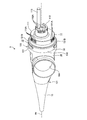
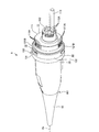
- FIG. 2 is an overall perspective view of the endoscope connector.
- FIG. 3 is an overall perspective view of the endoscope connector.
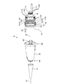
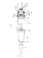
- FIG. 4 is an exploded perspective view of the endoscope connector.
- FIG. 5 is an exploded perspective view of the endoscope connector.
- FIG. 6 is a cross-sectional view of the endoscope connector.
- FIG. 7 is a cross-sectional view of the endoscope connector.
- FIG. 1 is a diagram showing an endoscope system 1 according to the present embodiment.
- the endoscope system 1 is a system that performs ultrasonic diagnosis in a subject such as a person using an ultrasonic endoscope.
- the endoscope system 1 includes an ultrasonic endoscope 2, an ultrasonic observation device 3, an endoscope observation device 4, and a display device 5.
- the ultrasonic endoscope 2 corresponds to an endoscope according to the present invention.
- the ultrasonic endoscope 2 allows a part to be inserted into the subject, transmits an ultrasonic pulse (acoustic pulse) toward a body wall in the subject, and reflects an ultrasonic echo reflected by the subject. And a function of outputting an echo signal in response to the received signal, and a function of imaging the inside of the subject and outputting an image signal.
- the detailed configuration of the ultrasonic endoscope 2 will be described later.
- the ultrasonic observation device 3 is electrically connected to the ultrasonic endoscope 2 via the ultrasonic cable 31 (FIG. 1), and outputs a pulse signal to the ultrasonic endoscope 2 via the ultrasonic cable 31. Output and an echo signal from the ultrasonic endoscope 2 are input. Then, the ultrasonic observation device 3 performs a predetermined process on the echo signal to generate an ultrasonic image.
- an endoscope connector 9 (FIG. 1) of the ultrasonic endoscope 2 described later is detachably connected.
- the endoscope observation device 4 includes a video processor 41 and a light source device 42.
- the video processor 41 inputs an image signal from the ultrasonic endoscope 2.
- the video processor 41 performs a predetermined process on the image signal to generate an endoscope image.
- the light source device 42 supplies illumination light for illuminating the inside of the subject to the ultrasonic endoscope 2.
- the display device 5 is configured using a liquid crystal and an organic EL (Electro Luminescence), and an ultrasonic image generated by the ultrasonic observation device 3, an endoscope image generated by the endoscope observation device 4, and the like. Is displayed.
- the ultrasonic endoscope 2 includes an insertion section 6, an operation section 7, a universal cord 8, and an endoscope connector 9.
- the distal end side (the distal end side in the direction of insertion into the subject) of the insertion section 6 will be referred to as only "the distal end or the distal end side”.
- the end side (the operation unit 7 side) is described only as “base end or base end side”.
- the insertion part 6 is a part to be inserted into the subject. As shown in FIG.
- the insertion portion 6 includes an ultrasonic probe 61 provided at a distal end, a rigid member 62 connected to a proximal end of the ultrasonic probe 61, and an ultrasonic probe 61 connected to a proximal end of the rigid member 62.
- the bending section 63 includes a bending section 63 that can be bent and a flexible tube 64 connected to the base end side of the bending section 63 and having flexibility.
- a light guide (not shown) for transmitting the illumination light supplied from the light source device 42, the above-described pulse signal and the like are provided inside the insertion section 6, the operation section 7, the universal cord 8, and the endoscope connector 9.
- a vibrator cable (not shown) for transmitting an echo signal and a signal cable (not shown) for transmitting an image signal are routed, and a conduit (not shown) for flowing a fluid is provided. .
- the ultrasonic probe 61 is a convex ultrasonic probe, and has a plurality of piezoelectric elements (not shown).
- the plurality of piezoelectric elements form a convex arc by being regularly arranged.
- the ultrasonic probe 61 has an acoustic lens and a matching layer in addition to the above-described piezoelectric element, and acquires an ultrasonic echo that contributes to an ultrasonic tomographic image inside the body wall of the subject.
- the pulse signal output from the ultrasonic observation device 3 is input to the ultrasonic probe 61 after passing through the ultrasonic cable 31 and the above-described transducer cable. Then, the ultrasonic probe 61 converts the pulse signal into an ultrasonic pulse and transmits the pulse signal into the subject. Further, the ultrasonic probe 61 converts an ultrasonic echo reflected at a site to be observed in the subject into an electric echo signal. Then, the echo signal is input to the ultrasonic observation device 3 after passing through the above-described transducer cable and the ultrasonic cable 31.
- the ultrasonic probe 61 is not limited to the convex ultrasonic probe, but may be a radial ultrasonic probe.
- the hard member 62 is a hard member made of a resin material or the like, and has a substantially columnar shape.
- the rigid member 62 is formed with a mounting hole, an imaging hole, an illumination hole, a treatment instrument channel, an air supply / water supply hole, and the like.
- These mounting holes, imaging holes, illumination holes, treatment instrument channels, and air / water supply holes are holes penetrating from the base end to the end of the rigid member 62, and specifically have the following functions.
- the attachment hole is a hole to which the ultrasonic probe 61 is attached from the tip side. Then, the above-described transducer cable is inserted into the mounting hole, and is electrically connected to the ultrasonic probe 61.
- the imaging hole is a hole for acquiring a subject image in the subject.
- An objective lens for converging the subject image and an image sensor for capturing the subject image condensed by the objective lens are provided inside the imaging hole. Then, the image sensor outputs an image signal to the signal cable described above.
- the illumination hole is a hole for irradiating the subject with illumination light. Then, the emission end of the above-described light guide is inserted into the illumination hole, and emits illumination light from the illumination hole.
- the treatment tool channel is a hole through which various treatment tools are projected to the outside.
- the air / water supply hole is a hole that communicates with the above-described conduit and blows the fluid flowing through the conduit to the outer surface of the objective lens.
- the operation section 7 is connected to the proximal end side of the insertion section 6 and receives various operations from a doctor or the like. As shown in FIG. 1, the operation unit 7 includes a bending knob 71 for performing a bending operation on the bending unit 63 and a plurality of operation members 72 for performing various operations.
- a treatment instrument tube (not shown) communicating with the above-described treatment instrument channel is provided inside the flexible tube 64 and the curved portion 63.
- the operating section 7 is provided with a treatment instrument insertion port 73 for inserting the treatment instrument into the treatment instrument tube.
- the universal cord 8 is a cord extending from the operation unit 7 and provided with the above-described light guide, the above-described vibrator cable, the above-described signal cable, the above-described conduit, and the like.
- the endoscope connector 9 is a connector for connecting the ultrasonic cable 31 and the universal cord 8, and is inserted into the endoscope observation device 4 by being inserted into the endoscope observation device 4. And a connector for connecting
- FIGS. 2 and 3 are overall perspective views of the endoscope connector 9.
- FIGS. 2 and 3 are views of the endoscope connector 9 viewed from opposite sides.
- 4 and 5 are exploded perspective views of the endoscope connector 9.
- illustration of the elastic member 13 is omitted for convenience of explanation.
- 6 and 7 are cross-sectional views of the endoscope connector 9.
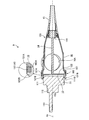
- FIG. 6 is a cross-sectional view of the endoscope connector 9 cut along a plane including the central axis Ax of the exterior member 10 and passing through the pair of locking portions 121B.
- FIG. 6 is a cross-sectional view of the endoscope connector 9 cut along a plane including the central axis Ax of the exterior member 10 and passing through the pair of locking portions 121B.
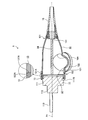
- FIG. 7 is a cross-sectional view of the endoscope connector 9 cut along a plane including the central axis Ax and avoiding the pair of locking portions 121B.
- the distal end side (the right side (the side on which the plug portion 11 is provided) in FIG. 2) of the endoscope connector 9 is referred to as a “tip or a tip”.
- the side of the endoscope connector 9 (the left side (the side on which the holding member 15 is provided) in FIG. 2) is described only as the "base end or base end side”.
- the endoscope connector 9 includes an exterior member 10, a plug portion 11, a metal member 12, and an elastic member 13 (FIGS. 2 to 4, 6, and 7). , A connection structure 14 (FIGS. 4 to 7), and a holding member 15.
- the exterior member 10 is made of a resin material having a larger linear expansion coefficient than a metal material. Examples of the resin material include PPSU (polysulfone) and PSU (polysulfone).
- the exterior member 10 has a substantially cylindrical shape as shown in FIGS. Then, the universal cord 8 is inserted into the exterior member 10 from the base end portion 101. Note that the base end portion 101 corresponds to “the other end of the exterior member” according to the present invention.
- a connector mounting hole 10A (FIGS. 2, 6, and 7) that connects the inside and outside of the exterior member 10 is formed on the outer peripheral surface of the exterior member 10.
- an ultrasonic connector is attached to the connector attaching hole 10A.
- the ultrasonic connector is an electric connector for electrically connecting the above-described transducer cable and the ultrasonic cable 31.
- the plug section 11 is electrically connected to the video processor 41 and optically connected to the light source device 42 when the endoscope connector 9 is inserted into the endoscope observation device 4. 2 to 7, and is attached to the distal end side of the metal member 12 as shown in FIGS.
- the plug section 11 includes first and second electrical connector sections 111 and 112 and a light guide base 113.
- the first electrical connector section 111 is located at the most proximal side of the plug section 11 and has a cylindrical shape extending along the central axis Ax.
- a plurality of first electrical contacts 111A (FIGS. 2 to 5) are provided along the circumferential direction on the distal end side of the outer peripheral surface of the first electrical connector portion 111.
- An O-ring 111B (FIGS. 4 to 7) is attached to the base end side of the outer peripheral surface of the first electrical connector section 111.
- the second electrical connector portion 112 is formed integrally with the end surface on the distal end side of the first electrical connector portion 111 and is formed in a columnar shape having an outer dimension smaller than that of the first electrical connector portion 111.
- a plurality of second electrical contacts 112A (FIGS. 2 to 5) are provided along the circumferential direction on the distal end side of the outer peripheral surface of the second electrical connector portion 112.
- the first and second electrical contacts 111A and 112A described above are electrically connected to signal lines in the above-described signal cable.
- the first and second electric contacts 111A and 112A are electrically connected to the video processor 41 when the endoscope connector 9 is inserted into the endoscope observation device 4. That is, the first and second electrical contacts 111A and 112A function as signal terminals.
- the light guide base 113 is attached to the end face on the distal end side of the second electric connector section 112, and protrudes from the end face. Further, the light guide base 113 is optically connected to the incident end of the above-described light guide inside the endoscope connector 9. When the endoscope connector 9 is inserted into the endoscope observation device 4, the light guide base 113 optically connects the light guide and the light source device 42 described above.
- the metal member 12 is provided between the distal end portion 102 of the exterior member 10 and the plug portion 11.
- the said tip part 102 is equivalent to "one end of the exterior member" which concerns on this invention.
- the metal member 12 is a member in which an outer shell 121 and a plate 122 are integrally formed, as shown in FIGS.
- the outer shell 121 has a cylindrical shape extending along the central axis Ax.
- an O-ring 121A is attached to the base end side of the outer peripheral surface as shown in FIGS. This O-ring 121A corresponds to the watertight member according to the present invention.
- the base end side of the outer shell 121 fits inside the distal end portion 102 of the exterior member 10 with the O-ring 121A interposed between the outer member 121 and the outer ring 121A.
- the distal end side of the outer shell 121 projects from the distal end portion 102 to the distal end side.
- the base end side of the plug portion 11 is fitted inside the distal end side of the outer shell 121 with the O-ring 111B interposed between the outer shell 121 and the O-ring 111B.
- the outer periphery 121 protrudes radially outward of the outer periphery 121 from the distal end side of the outer peripheral surface, and is formed in an arc shape in the circumferential direction around the center axis Ax.
- An extended pair of locking portions 121B is provided.
- the pair of locking portions 121B are provided at 180 ° rotationally symmetric positions about the central axis Ax, respectively, and are exposed to the outside. Then, when the endoscope connector 9 is inserted into the endoscope observation device 4, the pair of locking portions 121 ⁇ / b> B are locked to the endoscope observation device 4, and the endoscope observation device 4.
- the metal member 12 is electrically connected to a ground line (patient GND) in the signal cable described above.
- the pair of locking portions 121B are electrically connected to the video processor 41 when the endoscope connector 9 is inserted into the endoscope observation device 4. That is, the metal member 12 functions as a ground terminal.
- the plate body 122 is made of a metal material and has a disk shape.
- the plate 122 is formed integrally with the outer shell 121 and closes the inside of the outer shell 121.
- Each signal line in the above-described signal cable penetrates the plate 122 from the base end to the distal end in a state in which the signal line is electrically insulated from the plate 122 (the metal member 12). It is electrically connected to the electric contacts 111A and 112A.
- the elastic member 13 is formed integrally with the distal end side of the outer peripheral surface of the outer shell 121 by insert molding, outsert molding, or lining. More specifically, the elastic member 13 includes an annular portion 131 and a pair of projecting portions 132, as shown in FIGS. 2 to 4, 6, and 7.
- the annular portion 131 is located on the base end side with respect to the pair of locking portions 121B, and extends all around the central axis Ax in the circumferential direction. Then, as shown in FIG. 6 or FIG. 7, the end surface 131A on the base end side of the annular portion 131 is in a state where the base end side of the outer shell 121 is fitted inside the front end portion 102 of the exterior member 10.
- the end surfaces 131A and 102A that are in contact with each other are planes that are orthogonal to the central axis Ax and extend all around in the circumferential direction around the central axis Ax. Equivalent to.
- the pair of projecting portions 132 project from the distal end side of the annular portion 131, respectively, and extend in an arc shape in the circumferential direction around the central axis Ax. Then, the pair of projecting portions 132 are continuous with the pair of locking portions 121B in the circumferential direction around the central axis Ax. That is, similarly to the pair of locking portions 121B, the pair of projecting portions 132 are provided at 180 ° rotationally symmetric positions about the central axis Ax.
- the elastic member 13 is exposed to the outside and closes the gap between the distal end portion 102 of the exterior member 10 and the metal member 12 (the pair of locking portions 121B).
- the elastic member 13 is made of a resin material (for example, a silicone resin, a fluororesin, or the like) having an elastic modulus greater than that of the exterior member 10 and having electrical insulation and excellent chemical resistance. Have been.
- connection structure 14 is a structure extending along the central axis Ax.
- the distal end side is connected to the plate 122 and inserted into the exterior member 10.
- a screwing portion 141 with which the pressing member 15 is screwed is provided at the base end side of the connection structure 14.
- a screw groove is formed on the outer surface of the screw portion 141.
- the holding member 15 has a substantially cylindrical shape extending along the central axis Ax, and the universal cord 8 is inserted therein.
- a screw groove to be screwed into the screw groove of the screwing portion 141 is formed on the distal end side of the inner peripheral surface of the pressing member 15.
- the presser member 15 is screwed into the screwing portion 141 and changes its screwed state to advance and retreat along the central axis Ax with respect to the connection structure 14. Then, by changing the screwing state of the holding member 15 to the connection structure 14 and moving the holding member 15 to the distal end side with respect to the connection structure 14, the holding member 15 is attached to the base end portion 101 of the exterior member 10. Abut. That is, the exterior member 10 and the elastic member 13 are sandwiched between the metal member 12 and the pressing member 15. The elastic member 13 is compressed in a direction along the central axis Ax.
- the gap between the exterior member 10 and the metal member 12 is closed by the elastic member 13. For this reason, the difference in expansion rate or contraction rate between the exterior member 10 and the metal member 12 due to heat or chemical attack added during the reprocessing can be absorbed by the elastic member 13. Therefore, it is possible to suppress the occurrence of a gap between the exterior member 10 and the metal member 12 or the damage of the exterior member 10 due to heat or a chemical attack added during the reprocessing. That is, the influence of the reprocessing can be suppressed.
- the generation of a gap between the exterior member 10 and the metal member 12 can be suppressed, the residue of dirt and the like adhering when the ultrasonic endoscope 2 is used does not remain in the gap, and The process becomes easier. Further, since the influence of the reprocessing can be suppressed by the elastic member 13, it is not necessary to fill the adhesive between the exterior member 10 and the metal member 12. That is, the exterior member 10 can be easily removed from the metal member 12, and the member provided inside the exterior member 10 can be easily replaced.
- the metal member 12 is provided at the distal end portion 102 of the cylindrical exterior member 10.
- the elastic member 13 is provided between the distal end portion 102 and the metal member 12 (a pair of locking portions 121B). That is, since the metal member 12 is provided at the end portion of the exterior member 10, the metal member 12 is provided at a position other than the end portion with respect to the metal member 12. Can be easily removed.
- the endoscope connector 9 by connecting the metal member 12 and the pressing member 15 to both ends of the connection structure 14, respectively, the exterior member 10 and the elastic member 13 It is sandwiched between the holding member 15.
- the holding member 15 is screwed into the screwing portion 141 of the connection structure 14 and moves forward and backward along the central axis Ax with respect to the connection structure 14 by changing the screwing state. Therefore, the elastic member 13 can be appropriately compressed. That is, the difference in expansion rate or contraction rate between the exterior member 10 and the metal member 12 due to heat or chemical attack added during the reprocessing can be effectively absorbed by the elastic member 13.
- the O-ring 121A and the elastic member 13 can sufficiently secure watertightness between the distal end portion 102 and the metal member 12.
- the end surfaces 102A and 131A that come into contact with each other are orthogonal to the center axis Ax, and the center axis Ax is the center. It is a plane extending all around in the circumferential direction. For this reason, the shape of each of the end surfaces 102A and 131A can be simplified, the manufacture thereof can be facilitated, and the adhesion between the end surfaces 102A and 131A can be improved.
- the elastic member 13 is made of a material having electrical insulation. For this reason, the insulating property of the metal member 12 functioning as the ground terminal can be sufficiently ensured.
- the elastic member 13 is made of a material having chemical resistance. For this reason, it is possible to suppress the deterioration of the elastic member 13 during the reprocessing.
- the pair of locking portions 121 ⁇ / b> B are mechanically attached to the endoscope observation device 4 by being locked to the endoscope observation device 4.
- the metal member 12 has a function of mechanically connecting to the endoscope observation device 4 in addition to a function as a ground terminal. For this reason, the number of components can be reduced as compared with the case where a configuration for mechanically connecting to the endoscope observation device 4 is separately provided.
- the present invention should not be limited only to the above-described embodiments.
- the metal member 12 functions as a ground terminal.
- the present invention is not limited to this, and a configuration that functions as a signal terminal may be employed.
- the endoscope system 1 has both the function of generating an ultrasonic image and the function of generating an endoscope image.
- the present invention is not limited to this.
- a configuration having only a generating function may be employed. That is, a configuration in which the ultrasonic probe 61, the ultrasonic observation device 3, and the like are not provided may be adopted.
- the endoscope system 1 is used in the industrial field, and may be an endoscope system for observing the inside of a subject such as a mechanical structure.
Landscapes
- Health & Medical Sciences (AREA)
- Life Sciences & Earth Sciences (AREA)
- Surgery (AREA)
- Physics & Mathematics (AREA)
- Engineering & Computer Science (AREA)
- Medical Informatics (AREA)
- Animal Behavior & Ethology (AREA)
- Radiology & Medical Imaging (AREA)
- Veterinary Medicine (AREA)
- Nuclear Medicine, Radiotherapy & Molecular Imaging (AREA)
- Biomedical Technology (AREA)
- Heart & Thoracic Surgery (AREA)
- Biophysics (AREA)
- Molecular Biology (AREA)
- Pathology (AREA)
- General Health & Medical Sciences (AREA)
- Public Health (AREA)
- Optics & Photonics (AREA)
- Mechanical Engineering (AREA)
- Astronomy & Astrophysics (AREA)
- General Physics & Mathematics (AREA)
- Endoscopes (AREA)
- Instruments For Viewing The Inside Of Hollow Bodies (AREA)
- Ultra Sonic Daignosis Equipment (AREA)
Priority Applications (2)
| Application Number | Priority Date | Filing Date | Title |
|---|---|---|---|
| CN201980045186.3A CN112469322B (zh) | 2018-07-06 | 2019-07-02 | 内窥镜用连接器和内窥镜 |
| US17/136,576 US11992368B2 (en) | 2018-07-06 | 2020-12-29 | Endoscope connector and endoscope |
Applications Claiming Priority (2)
| Application Number | Priority Date | Filing Date | Title |
|---|---|---|---|
| JP2018129298A JP7099891B2 (ja) | 2018-07-06 | 2018-07-06 | 内視鏡用コネクタ及び内視鏡 |
| JP2018-129298 | 2018-07-06 |
Related Child Applications (1)
| Application Number | Title | Priority Date | Filing Date |
|---|---|---|---|
| US17/136,576 Continuation US11992368B2 (en) | 2018-07-06 | 2020-12-29 | Endoscope connector and endoscope |
Publications (1)
| Publication Number | Publication Date |
|---|---|
| WO2020009128A1 true WO2020009128A1 (ja) | 2020-01-09 |
Family
ID=69060980
Family Applications (1)
| Application Number | Title | Priority Date | Filing Date |
|---|---|---|---|
| PCT/JP2019/026384 Ceased WO2020009128A1 (ja) | 2018-07-06 | 2019-07-02 | 内視鏡用コネクタ及び内視鏡 |
Country Status (4)
| Country | Link |
|---|---|
| US (1) | US11992368B2 (enExample) |
| JP (1) | JP7099891B2 (enExample) |
| CN (1) | CN112469322B (enExample) |
| WO (1) | WO2020009128A1 (enExample) |
Families Citing this family (6)
| Publication number | Priority date | Publication date | Assignee | Title |
|---|---|---|---|---|
| JP1687236S (enExample) * | 2020-12-25 | 2021-06-07 | ||
| JP1687233S (enExample) * | 2020-12-25 | 2021-06-07 | ||
| JP1687235S (enExample) * | 2020-12-25 | 2021-06-07 | ||
| JP1687234S (enExample) * | 2020-12-25 | 2021-06-07 | ||
| USD1041004S1 (en) * | 2021-12-07 | 2024-09-03 | Guangzhou Red Pine Medical Instrument Co., Ltd. | Endoscope connector |
| US20240148234A1 (en) | 2022-11-07 | 2024-05-09 | Gyrus Acmi, Inc. D/B/A Olympus Surgical Technologies America | Light processing adapter for endoscope |
Citations (4)
| Publication number | Priority date | Publication date | Assignee | Title |
|---|---|---|---|---|
| WO2011052408A1 (ja) * | 2009-10-28 | 2011-05-05 | オリンパスメディカルシステムズ株式会社 | 医療機器用コネクタ |
| WO2013114661A1 (ja) * | 2012-01-31 | 2013-08-08 | オリンパスメディカルシステムズ株式会社 | 内視鏡 |
| WO2013114703A1 (ja) * | 2012-01-31 | 2013-08-08 | オリンパスメディカルシステムズ株式会社 | 内視鏡 |
| JP2016096039A (ja) * | 2014-11-14 | 2016-05-26 | 日本航空電子工業株式会社 | 防水コネクタ |
Family Cites Families (10)
| Publication number | Priority date | Publication date | Assignee | Title |
|---|---|---|---|---|
| JP2005168607A (ja) * | 2003-12-08 | 2005-06-30 | Olympus Corp | 内視鏡 |
| JP5147887B2 (ja) * | 2009-04-02 | 2013-02-20 | オリンパスメディカルシステムズ株式会社 | 内視鏡用撮像装置 |
| EP2371262B1 (en) * | 2009-07-23 | 2017-03-29 | Olympus Corporation | Endoscope apparatus |
| CN102639048B (zh) * | 2010-01-25 | 2015-03-25 | 奥林巴斯医疗株式会社 | 电子内窥镜 |
| CN107613838A (zh) * | 2015-05-29 | 2018-01-19 | 奥林巴斯株式会社 | 摄像装置、内窥镜系统以及摄像装置的制造方法 |
| CN107530056B (zh) * | 2015-08-31 | 2020-05-15 | 奥林巴斯株式会社 | 内窥镜用连接器 |
| JP6197150B2 (ja) | 2015-09-02 | 2017-09-13 | オリンパス株式会社 | 内視鏡 |
| JP2017113077A (ja) * | 2015-12-21 | 2017-06-29 | ソニー・オリンパスメディカルソリューションズ株式会社 | 内視鏡装置 |
| US9677284B1 (en) * | 2016-02-02 | 2017-06-13 | Barrett Aerospace Technologies, LLC | Thermally adaptive wall covering |
| JP2018099441A (ja) * | 2016-12-21 | 2018-06-28 | オリンパス株式会社 | 撮像装置および内視鏡 |
-
2018
- 2018-07-06 JP JP2018129298A patent/JP7099891B2/ja active Active
-
2019
- 2019-07-02 CN CN201980045186.3A patent/CN112469322B/zh active Active
- 2019-07-02 WO PCT/JP2019/026384 patent/WO2020009128A1/ja not_active Ceased
-
2020
- 2020-12-29 US US17/136,576 patent/US11992368B2/en active Active
Patent Citations (4)
| Publication number | Priority date | Publication date | Assignee | Title |
|---|---|---|---|---|
| WO2011052408A1 (ja) * | 2009-10-28 | 2011-05-05 | オリンパスメディカルシステムズ株式会社 | 医療機器用コネクタ |
| WO2013114661A1 (ja) * | 2012-01-31 | 2013-08-08 | オリンパスメディカルシステムズ株式会社 | 内視鏡 |
| WO2013114703A1 (ja) * | 2012-01-31 | 2013-08-08 | オリンパスメディカルシステムズ株式会社 | 内視鏡 |
| JP2016096039A (ja) * | 2014-11-14 | 2016-05-26 | 日本航空電子工業株式会社 | 防水コネクタ |
Also Published As
| Publication number | Publication date |
|---|---|
| US11992368B2 (en) | 2024-05-28 |
| JP2020005859A (ja) | 2020-01-16 |
| US20210113183A1 (en) | 2021-04-22 |
| CN112469322A (zh) | 2021-03-09 |
| JP7099891B2 (ja) | 2022-07-12 |
| CN112469322B (zh) | 2024-10-29 |
Similar Documents
| Publication | Publication Date | Title |
|---|---|---|
| WO2020009128A1 (ja) | 内視鏡用コネクタ及び内視鏡 | |
| JP6654699B2 (ja) | 超音波内視鏡 | |
| JP4618410B2 (ja) | 超音波内視鏡 | |
| JP5984525B2 (ja) | 超音波観察装置 | |
| US12290242B2 (en) | Camera head | |
| JP3665443B2 (ja) | 内視鏡 | |
| JP7155396B2 (ja) | 超音波内視鏡及び挿入管 | |
| JP4596141B2 (ja) | 超音波内視鏡 | |
| JP6033509B1 (ja) | 超音波プローブ | |
| WO2013183353A1 (ja) | 内視鏡 | |
| US10463238B2 (en) | Endoscope and hard member | |
| JP6133001B1 (ja) | 超音波振動子モジュールおよび超音波内視鏡 | |
| JP2020116044A (ja) | 内視鏡 | |
| CN111698948A (zh) | 超声波振子及超声波内窥镜 | |
| JP7441653B2 (ja) | カメラヘッド | |
| JP2006280407A (ja) | 超音波内視鏡 | |
| JP2023128309A (ja) | 内視鏡 | |
| JP3181937U (ja) | 超音波内視鏡の超音波コネクタ | |
| JP2001087262A (ja) | 内視鏡着脱型超音波検査装置 | |
| JP7223871B2 (ja) | 超音波内視鏡 | |
| US10244924B2 (en) | Endoscope | |
| JP2006158481A (ja) | 超音波内視鏡 | |
| JP2006255246A (ja) | 超音波内視鏡 | |
| JP2005265631A (ja) | Octプローブ及びoctプローブ用ケース |
Legal Events
| Date | Code | Title | Description |
|---|---|---|---|
| 121 | Ep: the epo has been informed by wipo that ep was designated in this application |
Ref document number: 19831271 Country of ref document: EP Kind code of ref document: A1 |
|
| NENP | Non-entry into the national phase |
Ref country code: DE |
|
| 122 | Ep: pct application non-entry in european phase |
Ref document number: 19831271 Country of ref document: EP Kind code of ref document: A1 |