WO2020009128A1 - 内視鏡用コネクタ及び内視鏡 - Google Patents
内視鏡用コネクタ及び内視鏡 Download PDFInfo
- Publication number
- WO2020009128A1 WO2020009128A1 PCT/JP2019/026384 JP2019026384W WO2020009128A1 WO 2020009128 A1 WO2020009128 A1 WO 2020009128A1 JP 2019026384 W JP2019026384 W JP 2019026384W WO 2020009128 A1 WO2020009128 A1 WO 2020009128A1
- Authority
- WO
- WIPO (PCT)
- Prior art keywords
- endoscope
- connector
- exterior member
- exterior
- metal member
- Prior art date
Links
Images

Classifications
-
- A—HUMAN NECESSITIES
- A61—MEDICAL OR VETERINARY SCIENCE; HYGIENE
- A61B—DIAGNOSIS; SURGERY; IDENTIFICATION
- A61B8/00—Diagnosis using ultrasonic, sonic or infrasonic waves
- A61B8/44—Constructional features of the ultrasonic, sonic or infrasonic diagnostic device
- A61B8/4444—Constructional features of the ultrasonic, sonic or infrasonic diagnostic device related to the probe
- A61B8/445—Details of catheter construction
-
- A—HUMAN NECESSITIES
- A61—MEDICAL OR VETERINARY SCIENCE; HYGIENE
- A61B—DIAGNOSIS; SURGERY; IDENTIFICATION
- A61B8/00—Diagnosis using ultrasonic, sonic or infrasonic waves
- A61B8/44—Constructional features of the ultrasonic, sonic or infrasonic diagnostic device
- A61B8/4444—Constructional features of the ultrasonic, sonic or infrasonic diagnostic device related to the probe
- A61B8/4455—Features of the external shape of the probe, e.g. ergonomic aspects
-
- A—HUMAN NECESSITIES
- A61—MEDICAL OR VETERINARY SCIENCE; HYGIENE
- A61B—DIAGNOSIS; SURGERY; IDENTIFICATION
- A61B1/00—Instruments for performing medical examinations of the interior of cavities or tubes of the body by visual or photographical inspection, e.g. endoscopes; Illuminating arrangements therefor
- A61B1/00112—Connection or coupling means
- A61B1/00121—Connectors, fasteners and adapters, e.g. on the endoscope handle
- A61B1/00124—Connectors, fasteners and adapters, e.g. on the endoscope handle electrical, e.g. electrical plug-and-socket connection
-
- A—HUMAN NECESSITIES
- A61—MEDICAL OR VETERINARY SCIENCE; HYGIENE
- A61B—DIAGNOSIS; SURGERY; IDENTIFICATION
- A61B1/00—Instruments for performing medical examinations of the interior of cavities or tubes of the body by visual or photographical inspection, e.g. endoscopes; Illuminating arrangements therefor
- A61B1/00112—Connection or coupling means
- A61B1/00121—Connectors, fasteners and adapters, e.g. on the endoscope handle
- A61B1/00126—Connectors, fasteners and adapters, e.g. on the endoscope handle optical, e.g. for light supply cables
-
- A—HUMAN NECESSITIES
- A61—MEDICAL OR VETERINARY SCIENCE; HYGIENE
- A61B—DIAGNOSIS; SURGERY; IDENTIFICATION
- A61B1/00—Instruments for performing medical examinations of the interior of cavities or tubes of the body by visual or photographical inspection, e.g. endoscopes; Illuminating arrangements therefor
- A61B1/00112—Connection or coupling means
- A61B1/00121—Connectors, fasteners and adapters, e.g. on the endoscope handle
- A61B1/00128—Connectors, fasteners and adapters, e.g. on the endoscope handle mechanical, e.g. for tubes or pipes
-
- A—HUMAN NECESSITIES
- A61—MEDICAL OR VETERINARY SCIENCE; HYGIENE
- A61B—DIAGNOSIS; SURGERY; IDENTIFICATION
- A61B8/00—Diagnosis using ultrasonic, sonic or infrasonic waves
- A61B8/12—Diagnosis using ultrasonic, sonic or infrasonic waves in body cavities or body tracts, e.g. by using catheters
-
- G—PHYSICS
- G02—OPTICS
- G02B—OPTICAL ELEMENTS, SYSTEMS OR APPARATUS
- G02B23/00—Telescopes, e.g. binoculars; Periscopes; Instruments for viewing the inside of hollow bodies; Viewfinders; Optical aiming or sighting devices
- G02B23/24—Instruments or systems for viewing the inside of hollow bodies, e.g. fibrescopes
-
- A—HUMAN NECESSITIES
- A61—MEDICAL OR VETERINARY SCIENCE; HYGIENE
- A61B—DIAGNOSIS; SURGERY; IDENTIFICATION
- A61B1/00—Instruments for performing medical examinations of the interior of cavities or tubes of the body by visual or photographical inspection, e.g. endoscopes; Illuminating arrangements therefor
- A61B1/06—Instruments for performing medical examinations of the interior of cavities or tubes of the body by visual or photographical inspection, e.g. endoscopes; Illuminating arrangements therefor with illuminating arrangements
- A61B1/0661—Endoscope light sources
- A61B1/0669—Endoscope light sources at proximal end of an endoscope
-
- A—HUMAN NECESSITIES
- A61—MEDICAL OR VETERINARY SCIENCE; HYGIENE
- A61B—DIAGNOSIS; SURGERY; IDENTIFICATION
- A61B1/00—Instruments for performing medical examinations of the interior of cavities or tubes of the body by visual or photographical inspection, e.g. endoscopes; Illuminating arrangements therefor
- A61B1/06—Instruments for performing medical examinations of the interior of cavities or tubes of the body by visual or photographical inspection, e.g. endoscopes; Illuminating arrangements therefor with illuminating arrangements
- A61B1/07—Instruments for performing medical examinations of the interior of cavities or tubes of the body by visual or photographical inspection, e.g. endoscopes; Illuminating arrangements therefor with illuminating arrangements using light-conductive means, e.g. optical fibres
Definitions
- the present invention relates to an endoscope connector and an endoscope.
- an endoscope system in which an endoscope that is inserted into a subject and captures an image of the subject in the subject and an endoscope observation device that processes an image signal obtained by the capturing are connected by an endoscope connector.
- the endoscope connector described in Patent Literature 1 includes a metal member (first and second electrical contacts and the like) electrically connected to an endoscope observation device, and an exterior member (exterior) made of a resin material. Housing).
- the endoscope connector is generally subjected to reprocessing such as sterilization or disinfection before or after use of the endoscope.
- reprocessing such as sterilization or disinfection before or after use of the endoscope.
- both the metal member and the exterior member are exposed to the outside.
- the material of the metal member and the material of the exterior member are different.
- the metal member and the exterior member have a difference in expansion rate or contraction rate due to heat or chemical attack applied during reprocessing. Therefore, a gap may be generated between the metal member and the exterior member, or the exterior member may be damaged due to heat or a chemical attack added during the reprocessing.
- the present invention has been made in view of the above, and an endoscope connector and an endoscope that can easily replace a member provided inside an exterior member while suppressing the influence of reprocessing.
- the purpose is to provide.
- a connector for an endoscope includes a metal member exposed to the outside and electrically connected to an endoscope observation device; An exterior member made of a resin material having a larger coefficient of linear expansion, and an elastic member having an elastic modulus greater than that of the exterior member and being exposed to the outside to close a gap between the exterior member and the metal member. And characterized in that:
- the exterior member has a cylindrical shape
- the metal member is provided at one end of the exterior member
- the elastic member is the exterior member. Is provided between one end of the metal member and the metal member.
- connection structure which is inserted into the exterior member and one end of which is connected to the metal member, and which is attached to the other end of the connection structure.
- a pressing member abutting on the other end of the exterior member, wherein the exterior member and the elastic member are sandwiched between the metal member and the pressing member.
- the pressing member is screwed to the other end of the connection structure, and the connection structure is changed by changing the screwing state. On the other hand, it moves forward and backward along the central axis of the exterior member.
- a contact surface where one end of the exterior member and the elastic member abut each other is orthogonal to a central axis of the exterior member, and the central axis is It is a plane extending over the entire circumference in the circumferential direction around the center.
- the elastic member is made of an electrically insulating material.
- the elastic member is made of a material having chemical resistance.
- the metal member is mechanically connected to the endoscope observation device by being locked to the endoscope observation device. It is characterized by.
- the metal member is a ground terminal electrically connected to the endoscope observation device.
- a watertight member is provided between the exterior member and the metal member.
- the endoscope according to the present invention has a distal end and a proximal end, an insertion portion provided with an ultrasonic probe on the distal end side, an operation portion provided on the proximal end side of the insertion portion, and an external device.
- the connector for an endoscope and the endoscope according to the present invention it is possible to easily replace a member provided inside the exterior member while suppressing the influence of the reprocessing.
- FIG. 1 is a diagram showing an endoscope system according to the present embodiment.
- FIG. 2 is an overall perspective view of the endoscope connector.
- FIG. 3 is an overall perspective view of the endoscope connector.
- FIG. 4 is an exploded perspective view of the endoscope connector.
- FIG. 5 is an exploded perspective view of the endoscope connector.
- FIG. 6 is a cross-sectional view of the endoscope connector.
- FIG. 7 is a cross-sectional view of the endoscope connector.
- FIG. 1 is a diagram showing an endoscope system 1 according to the present embodiment.
- the endoscope system 1 is a system that performs ultrasonic diagnosis in a subject such as a person using an ultrasonic endoscope.
- the endoscope system 1 includes an ultrasonic endoscope 2, an ultrasonic observation device 3, an endoscope observation device 4, and a display device 5.
- the ultrasonic endoscope 2 corresponds to an endoscope according to the present invention.
- the ultrasonic endoscope 2 allows a part to be inserted into the subject, transmits an ultrasonic pulse (acoustic pulse) toward a body wall in the subject, and reflects an ultrasonic echo reflected by the subject. And a function of outputting an echo signal in response to the received signal, and a function of imaging the inside of the subject and outputting an image signal.
- the detailed configuration of the ultrasonic endoscope 2 will be described later.
- the ultrasonic observation device 3 is electrically connected to the ultrasonic endoscope 2 via the ultrasonic cable 31 (FIG. 1), and outputs a pulse signal to the ultrasonic endoscope 2 via the ultrasonic cable 31. Output and an echo signal from the ultrasonic endoscope 2 are input. Then, the ultrasonic observation device 3 performs a predetermined process on the echo signal to generate an ultrasonic image.
- an endoscope connector 9 (FIG. 1) of the ultrasonic endoscope 2 described later is detachably connected.
- the endoscope observation device 4 includes a video processor 41 and a light source device 42.
- the video processor 41 inputs an image signal from the ultrasonic endoscope 2.
- the video processor 41 performs a predetermined process on the image signal to generate an endoscope image.
- the light source device 42 supplies illumination light for illuminating the inside of the subject to the ultrasonic endoscope 2.
- the display device 5 is configured using a liquid crystal and an organic EL (Electro Luminescence), and an ultrasonic image generated by the ultrasonic observation device 3, an endoscope image generated by the endoscope observation device 4, and the like. Is displayed.
- the ultrasonic endoscope 2 includes an insertion section 6, an operation section 7, a universal cord 8, and an endoscope connector 9.
- the distal end side (the distal end side in the direction of insertion into the subject) of the insertion section 6 will be referred to as only "the distal end or the distal end side”.
- the end side (the operation unit 7 side) is described only as “base end or base end side”.
- the insertion part 6 is a part to be inserted into the subject. As shown in FIG.
- the insertion portion 6 includes an ultrasonic probe 61 provided at a distal end, a rigid member 62 connected to a proximal end of the ultrasonic probe 61, and an ultrasonic probe 61 connected to a proximal end of the rigid member 62.
- the bending section 63 includes a bending section 63 that can be bent and a flexible tube 64 connected to the base end side of the bending section 63 and having flexibility.
- a light guide (not shown) for transmitting the illumination light supplied from the light source device 42, the above-described pulse signal and the like are provided inside the insertion section 6, the operation section 7, the universal cord 8, and the endoscope connector 9.
- a vibrator cable (not shown) for transmitting an echo signal and a signal cable (not shown) for transmitting an image signal are routed, and a conduit (not shown) for flowing a fluid is provided. .
- the ultrasonic probe 61 is a convex ultrasonic probe, and has a plurality of piezoelectric elements (not shown).
- the plurality of piezoelectric elements form a convex arc by being regularly arranged.
- the ultrasonic probe 61 has an acoustic lens and a matching layer in addition to the above-described piezoelectric element, and acquires an ultrasonic echo that contributes to an ultrasonic tomographic image inside the body wall of the subject.
- the pulse signal output from the ultrasonic observation device 3 is input to the ultrasonic probe 61 after passing through the ultrasonic cable 31 and the above-described transducer cable. Then, the ultrasonic probe 61 converts the pulse signal into an ultrasonic pulse and transmits the pulse signal into the subject. Further, the ultrasonic probe 61 converts an ultrasonic echo reflected at a site to be observed in the subject into an electric echo signal. Then, the echo signal is input to the ultrasonic observation device 3 after passing through the above-described transducer cable and the ultrasonic cable 31.
- the ultrasonic probe 61 is not limited to the convex ultrasonic probe, but may be a radial ultrasonic probe.
- the hard member 62 is a hard member made of a resin material or the like, and has a substantially columnar shape.
- the rigid member 62 is formed with a mounting hole, an imaging hole, an illumination hole, a treatment instrument channel, an air supply / water supply hole, and the like.
- These mounting holes, imaging holes, illumination holes, treatment instrument channels, and air / water supply holes are holes penetrating from the base end to the end of the rigid member 62, and specifically have the following functions.
- the attachment hole is a hole to which the ultrasonic probe 61 is attached from the tip side. Then, the above-described transducer cable is inserted into the mounting hole, and is electrically connected to the ultrasonic probe 61.
- the imaging hole is a hole for acquiring a subject image in the subject.
- An objective lens for converging the subject image and an image sensor for capturing the subject image condensed by the objective lens are provided inside the imaging hole. Then, the image sensor outputs an image signal to the signal cable described above.
- the illumination hole is a hole for irradiating the subject with illumination light. Then, the emission end of the above-described light guide is inserted into the illumination hole, and emits illumination light from the illumination hole.
- the treatment tool channel is a hole through which various treatment tools are projected to the outside.
- the air / water supply hole is a hole that communicates with the above-described conduit and blows the fluid flowing through the conduit to the outer surface of the objective lens.
- the operation section 7 is connected to the proximal end side of the insertion section 6 and receives various operations from a doctor or the like. As shown in FIG. 1, the operation unit 7 includes a bending knob 71 for performing a bending operation on the bending unit 63 and a plurality of operation members 72 for performing various operations.
- a treatment instrument tube (not shown) communicating with the above-described treatment instrument channel is provided inside the flexible tube 64 and the curved portion 63.
- the operating section 7 is provided with a treatment instrument insertion port 73 for inserting the treatment instrument into the treatment instrument tube.
- the universal cord 8 is a cord extending from the operation unit 7 and provided with the above-described light guide, the above-described vibrator cable, the above-described signal cable, the above-described conduit, and the like.
- the endoscope connector 9 is a connector for connecting the ultrasonic cable 31 and the universal cord 8, and is inserted into the endoscope observation device 4 by being inserted into the endoscope observation device 4. And a connector for connecting
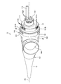
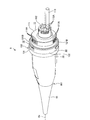
- FIGS. 2 and 3 are overall perspective views of the endoscope connector 9.
- FIGS. 2 and 3 are views of the endoscope connector 9 viewed from opposite sides.
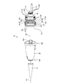
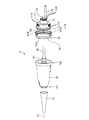
- 4 and 5 are exploded perspective views of the endoscope connector 9.
- illustration of the elastic member 13 is omitted for convenience of explanation.
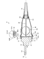
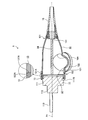
- 6 and 7 are cross-sectional views of the endoscope connector 9.
- FIG. 6 is a cross-sectional view of the endoscope connector 9 cut along a plane including the central axis Ax of the exterior member 10 and passing through the pair of locking portions 121B.
- FIG. 6 is a cross-sectional view of the endoscope connector 9 cut along a plane including the central axis Ax of the exterior member 10 and passing through the pair of locking portions 121B.
- FIG. 7 is a cross-sectional view of the endoscope connector 9 cut along a plane including the central axis Ax and avoiding the pair of locking portions 121B.
- the distal end side (the right side (the side on which the plug portion 11 is provided) in FIG. 2) of the endoscope connector 9 is referred to as a “tip or a tip”.
- the side of the endoscope connector 9 (the left side (the side on which the holding member 15 is provided) in FIG. 2) is described only as the "base end or base end side”.
- the endoscope connector 9 includes an exterior member 10, a plug portion 11, a metal member 12, and an elastic member 13 (FIGS. 2 to 4, 6, and 7). , A connection structure 14 (FIGS. 4 to 7), and a holding member 15.
- the exterior member 10 is made of a resin material having a larger linear expansion coefficient than a metal material. Examples of the resin material include PPSU (polysulfone) and PSU (polysulfone).
- the exterior member 10 has a substantially cylindrical shape as shown in FIGS. Then, the universal cord 8 is inserted into the exterior member 10 from the base end portion 101. Note that the base end portion 101 corresponds to “the other end of the exterior member” according to the present invention.
- a connector mounting hole 10A (FIGS. 2, 6, and 7) that connects the inside and outside of the exterior member 10 is formed on the outer peripheral surface of the exterior member 10.
- an ultrasonic connector is attached to the connector attaching hole 10A.
- the ultrasonic connector is an electric connector for electrically connecting the above-described transducer cable and the ultrasonic cable 31.
- the plug section 11 is electrically connected to the video processor 41 and optically connected to the light source device 42 when the endoscope connector 9 is inserted into the endoscope observation device 4. 2 to 7, and is attached to the distal end side of the metal member 12 as shown in FIGS.
- the plug section 11 includes first and second electrical connector sections 111 and 112 and a light guide base 113.
- the first electrical connector section 111 is located at the most proximal side of the plug section 11 and has a cylindrical shape extending along the central axis Ax.
- a plurality of first electrical contacts 111A (FIGS. 2 to 5) are provided along the circumferential direction on the distal end side of the outer peripheral surface of the first electrical connector portion 111.
- An O-ring 111B (FIGS. 4 to 7) is attached to the base end side of the outer peripheral surface of the first electrical connector section 111.
- the second electrical connector portion 112 is formed integrally with the end surface on the distal end side of the first electrical connector portion 111 and is formed in a columnar shape having an outer dimension smaller than that of the first electrical connector portion 111.
- a plurality of second electrical contacts 112A (FIGS. 2 to 5) are provided along the circumferential direction on the distal end side of the outer peripheral surface of the second electrical connector portion 112.
- the first and second electrical contacts 111A and 112A described above are electrically connected to signal lines in the above-described signal cable.
- the first and second electric contacts 111A and 112A are electrically connected to the video processor 41 when the endoscope connector 9 is inserted into the endoscope observation device 4. That is, the first and second electrical contacts 111A and 112A function as signal terminals.
- the light guide base 113 is attached to the end face on the distal end side of the second electric connector section 112, and protrudes from the end face. Further, the light guide base 113 is optically connected to the incident end of the above-described light guide inside the endoscope connector 9. When the endoscope connector 9 is inserted into the endoscope observation device 4, the light guide base 113 optically connects the light guide and the light source device 42 described above.
- the metal member 12 is provided between the distal end portion 102 of the exterior member 10 and the plug portion 11.
- the said tip part 102 is equivalent to "one end of the exterior member" which concerns on this invention.
- the metal member 12 is a member in which an outer shell 121 and a plate 122 are integrally formed, as shown in FIGS.
- the outer shell 121 has a cylindrical shape extending along the central axis Ax.
- an O-ring 121A is attached to the base end side of the outer peripheral surface as shown in FIGS. This O-ring 121A corresponds to the watertight member according to the present invention.
- the base end side of the outer shell 121 fits inside the distal end portion 102 of the exterior member 10 with the O-ring 121A interposed between the outer member 121 and the outer ring 121A.
- the distal end side of the outer shell 121 projects from the distal end portion 102 to the distal end side.
- the base end side of the plug portion 11 is fitted inside the distal end side of the outer shell 121 with the O-ring 111B interposed between the outer shell 121 and the O-ring 111B.
- the outer periphery 121 protrudes radially outward of the outer periphery 121 from the distal end side of the outer peripheral surface, and is formed in an arc shape in the circumferential direction around the center axis Ax.
- An extended pair of locking portions 121B is provided.
- the pair of locking portions 121B are provided at 180 ° rotationally symmetric positions about the central axis Ax, respectively, and are exposed to the outside. Then, when the endoscope connector 9 is inserted into the endoscope observation device 4, the pair of locking portions 121 ⁇ / b> B are locked to the endoscope observation device 4, and the endoscope observation device 4.
- the metal member 12 is electrically connected to a ground line (patient GND) in the signal cable described above.
- the pair of locking portions 121B are electrically connected to the video processor 41 when the endoscope connector 9 is inserted into the endoscope observation device 4. That is, the metal member 12 functions as a ground terminal.
- the plate body 122 is made of a metal material and has a disk shape.
- the plate 122 is formed integrally with the outer shell 121 and closes the inside of the outer shell 121.
- Each signal line in the above-described signal cable penetrates the plate 122 from the base end to the distal end in a state in which the signal line is electrically insulated from the plate 122 (the metal member 12). It is electrically connected to the electric contacts 111A and 112A.
- the elastic member 13 is formed integrally with the distal end side of the outer peripheral surface of the outer shell 121 by insert molding, outsert molding, or lining. More specifically, the elastic member 13 includes an annular portion 131 and a pair of projecting portions 132, as shown in FIGS. 2 to 4, 6, and 7.
- the annular portion 131 is located on the base end side with respect to the pair of locking portions 121B, and extends all around the central axis Ax in the circumferential direction. Then, as shown in FIG. 6 or FIG. 7, the end surface 131A on the base end side of the annular portion 131 is in a state where the base end side of the outer shell 121 is fitted inside the front end portion 102 of the exterior member 10.
- the end surfaces 131A and 102A that are in contact with each other are planes that are orthogonal to the central axis Ax and extend all around in the circumferential direction around the central axis Ax. Equivalent to.
- the pair of projecting portions 132 project from the distal end side of the annular portion 131, respectively, and extend in an arc shape in the circumferential direction around the central axis Ax. Then, the pair of projecting portions 132 are continuous with the pair of locking portions 121B in the circumferential direction around the central axis Ax. That is, similarly to the pair of locking portions 121B, the pair of projecting portions 132 are provided at 180 ° rotationally symmetric positions about the central axis Ax.
- the elastic member 13 is exposed to the outside and closes the gap between the distal end portion 102 of the exterior member 10 and the metal member 12 (the pair of locking portions 121B).
- the elastic member 13 is made of a resin material (for example, a silicone resin, a fluororesin, or the like) having an elastic modulus greater than that of the exterior member 10 and having electrical insulation and excellent chemical resistance. Have been.
- connection structure 14 is a structure extending along the central axis Ax.
- the distal end side is connected to the plate 122 and inserted into the exterior member 10.
- a screwing portion 141 with which the pressing member 15 is screwed is provided at the base end side of the connection structure 14.
- a screw groove is formed on the outer surface of the screw portion 141.
- the holding member 15 has a substantially cylindrical shape extending along the central axis Ax, and the universal cord 8 is inserted therein.
- a screw groove to be screwed into the screw groove of the screwing portion 141 is formed on the distal end side of the inner peripheral surface of the pressing member 15.
- the presser member 15 is screwed into the screwing portion 141 and changes its screwed state to advance and retreat along the central axis Ax with respect to the connection structure 14. Then, by changing the screwing state of the holding member 15 to the connection structure 14 and moving the holding member 15 to the distal end side with respect to the connection structure 14, the holding member 15 is attached to the base end portion 101 of the exterior member 10. Abut. That is, the exterior member 10 and the elastic member 13 are sandwiched between the metal member 12 and the pressing member 15. The elastic member 13 is compressed in a direction along the central axis Ax.
- the gap between the exterior member 10 and the metal member 12 is closed by the elastic member 13. For this reason, the difference in expansion rate or contraction rate between the exterior member 10 and the metal member 12 due to heat or chemical attack added during the reprocessing can be absorbed by the elastic member 13. Therefore, it is possible to suppress the occurrence of a gap between the exterior member 10 and the metal member 12 or the damage of the exterior member 10 due to heat or a chemical attack added during the reprocessing. That is, the influence of the reprocessing can be suppressed.
- the generation of a gap between the exterior member 10 and the metal member 12 can be suppressed, the residue of dirt and the like adhering when the ultrasonic endoscope 2 is used does not remain in the gap, and The process becomes easier. Further, since the influence of the reprocessing can be suppressed by the elastic member 13, it is not necessary to fill the adhesive between the exterior member 10 and the metal member 12. That is, the exterior member 10 can be easily removed from the metal member 12, and the member provided inside the exterior member 10 can be easily replaced.
- the metal member 12 is provided at the distal end portion 102 of the cylindrical exterior member 10.
- the elastic member 13 is provided between the distal end portion 102 and the metal member 12 (a pair of locking portions 121B). That is, since the metal member 12 is provided at the end portion of the exterior member 10, the metal member 12 is provided at a position other than the end portion with respect to the metal member 12. Can be easily removed.
- the endoscope connector 9 by connecting the metal member 12 and the pressing member 15 to both ends of the connection structure 14, respectively, the exterior member 10 and the elastic member 13 It is sandwiched between the holding member 15.
- the holding member 15 is screwed into the screwing portion 141 of the connection structure 14 and moves forward and backward along the central axis Ax with respect to the connection structure 14 by changing the screwing state. Therefore, the elastic member 13 can be appropriately compressed. That is, the difference in expansion rate or contraction rate between the exterior member 10 and the metal member 12 due to heat or chemical attack added during the reprocessing can be effectively absorbed by the elastic member 13.
- the O-ring 121A and the elastic member 13 can sufficiently secure watertightness between the distal end portion 102 and the metal member 12.
- the end surfaces 102A and 131A that come into contact with each other are orthogonal to the center axis Ax, and the center axis Ax is the center. It is a plane extending all around in the circumferential direction. For this reason, the shape of each of the end surfaces 102A and 131A can be simplified, the manufacture thereof can be facilitated, and the adhesion between the end surfaces 102A and 131A can be improved.
- the elastic member 13 is made of a material having electrical insulation. For this reason, the insulating property of the metal member 12 functioning as the ground terminal can be sufficiently ensured.
- the elastic member 13 is made of a material having chemical resistance. For this reason, it is possible to suppress the deterioration of the elastic member 13 during the reprocessing.
- the pair of locking portions 121 ⁇ / b> B are mechanically attached to the endoscope observation device 4 by being locked to the endoscope observation device 4.
- the metal member 12 has a function of mechanically connecting to the endoscope observation device 4 in addition to a function as a ground terminal. For this reason, the number of components can be reduced as compared with the case where a configuration for mechanically connecting to the endoscope observation device 4 is separately provided.
- the present invention should not be limited only to the above-described embodiments.
- the metal member 12 functions as a ground terminal.
- the present invention is not limited to this, and a configuration that functions as a signal terminal may be employed.
- the endoscope system 1 has both the function of generating an ultrasonic image and the function of generating an endoscope image.
- the present invention is not limited to this.
- a configuration having only a generating function may be employed. That is, a configuration in which the ultrasonic probe 61, the ultrasonic observation device 3, and the like are not provided may be adopted.
- the endoscope system 1 is used in the industrial field, and may be an endoscope system for observing the inside of a subject such as a mechanical structure.
Abstract
内視鏡用コネクタ9は、外部に露出し、内視鏡観察装置に対して電気的に接続する金属部材12と、金属部材12よりも大きな線膨張係数を有する樹脂材料によって構成された外装部材10と、外装部材10よりも大きな弾性率を有するとともに、外部に露出し、外装部材10及び金属部材12間の隙間を閉塞する弾性部材13とを備える。
Description
本発明は、内視鏡用コネクタ及び内視鏡に関する。
従来、被検体内に挿入されて当該被検体内の被写体像を撮像する内視鏡と当該撮像による画像信号を処理する内視鏡観察装置とを内視鏡用コネクタによって接続した内視鏡システムが知られている(例えば、特許文献1参照)。
特許文献1に記載の内視鏡用コネクタは、内視鏡観察装置に対して電気的に接続する金属部材(第1,第2電気接点等)と、樹脂材料によって構成された外装部材(外装筐体)とを備える。
特許文献1に記載の内視鏡用コネクタは、内視鏡観察装置に対して電気的に接続する金属部材(第1,第2電気接点等)と、樹脂材料によって構成された外装部材(外装筐体)とを備える。
ところで、内視鏡用コネクタは、一般的に、内視鏡の使用前または使用後には、滅菌処理や消毒処理等のリプロセスが行われる。
特許文献1に記載の内視鏡用コネクタでは、金属部材及び外装部材の双方は、外部に露出している。また、金属部材と外装部材とは、材料が異なる。言い換えれば、金属部材と外装部材とは、リプロセス時に付加される熱やケミカルアタックによる膨張率または収縮率に差がある。このため、リプロセス時に付加される熱やケミカルアタックによって、金属部材と外装部材との間に隙間が発生する、または外装部材が破損してしまう虞がある。例えば、金属部材と外装部材との間に隙間が発生すると、内視鏡の使用時に付着する汚物等の残差が当該隙間に残り、リプロセスが困難になる。
また、リプロセスによる影響(隙間の発生または外装部材の破損)を抑制するために、金属部材と外装部材との間に接着剤を充填することが考えられる。しかしながら、接着剤を充填した場合には、金属部材に対して外装部材を取り外すことが困難なものとなり、当該外装部材の内部に設けられた部材を交換することが難しい。
そこで、リプロセスによる影響を抑制しつつ、外装部材の内部に設けられた部材を容易に交換することができる技術が要望されている。
本発明は、上記に鑑みてなされたものであって、リプロセスによる影響を抑制しつつ、外装部材の内部に設けられた部材を容易に交換することができる内視鏡用コネクタ及び内視鏡を提供することを目的とする。
上述した課題を解決し、目的を達成するために、本発明に係る内視鏡用コネクタは、外部に露出し、内視鏡観察装置に対して電気的に接続する金属部材と、前記金属部材よりも大きな線膨張係数を有する樹脂材料によって構成された外装部材と、前記外装部材よりも大きな弾性率を有するとともに、外部に露出し、前記外装部材及び前記金属部材間の隙間を閉塞する弾性部材とを備えることを特徴とする。
また、本発明に係る内視鏡用コネクタでは、上記発明において、前記外装部材は、筒形状を有し、前記金属部材は、前記外装部材の一端に設けられ、前記弾性部材は、前記外装部材の一端と前記金属部材との間に設けられていることを特徴とする。
また、本発明に係る内視鏡用コネクタでは、上記発明において、前記外装部材の内部に挿通され、一端側が前記金属部材に接続された接続構造体と、前記接続構造体の他端に取り付けられ、前記外装部材の他端に当接する押え部材とをさらに備え、前記外装部材及び前記弾性部材は、前記金属部材と前記押え部材との間に挟持されることを特徴とする。
また、本発明に係る内視鏡用コネクタでは、上記発明において、前記押え部材は、前記接続構造体の他端に対して螺合し、当該螺合状態を変更することによって当該接続構造体に対して前記外装部材の中心軸に沿って進退移動することを特徴とする。
また、本発明に係る内視鏡用コネクタでは、上記発明において、前記外装部材の一端及び前記弾性部材が互いに当接する当接面は、前記外装部材の中心軸に直交するとともに、当該中心軸を中心とする周方向の全周に延在した平面であることを特徴とする。
また、本発明に係る内視鏡用コネクタでは、上記発明において、前記弾性部材は、電気的に絶縁性を有する材料によって構成されていることを特徴とする。
また、本発明に係る内視鏡用コネクタでは、上記発明において、前記弾性部材は、耐薬品性を有する材料によって構成されていることを特徴とする。
また、本発明に係る内視鏡用コネクタでは、上記発明において、前記金属部材は、前記内視鏡観察装置に係止されることによって当該内視鏡観察装置に対して機械的に接続することを特徴とする。
また、本発明に係る内視鏡用コネクタでは、上記発明において、前記金属部材は、前記内視鏡観察装置に対して電気的に接続するグラウンド端子であることを特徴とする。
また、本発明に係る内視鏡用コネクタでは、上記発明において、前記外装部材及び前記金属部材間には、水密部材が設けられていることを特徴とする。
また、本発明に係る内視鏡は、先端と基端とを有し、先端側に超音波プローブが設けられた挿入部と、前記挿入部の基端側に設けられた操作部と、外部に露出し、内視鏡観察装置に対して電気的に接続する金属部材と、前記金属部材よりも大きな線膨張係数を有する樹脂材料によって構成された外装部材と、前記外装部材よりも大きな弾性率を有するとともに、外部に露出し、前記外装部材及び前記金属部材間の隙間を閉塞する弾性部材と、を備えた内視鏡用コネクタと、を備えることを特徴とすることを特徴とする。
本発明に係る内視鏡用コネクタ及び内視鏡によれば、リプロセスによる影響を抑制しつつ、外装部材の内部に設けられた部材を容易に交換することができる、という効果を奏する。
以下に、図面を参照して、本発明を実施するための形態(以下、実施の形態)について説明する。なお、以下に説明する実施の形態によって本発明が限定されるものではない。さらに、図面の記載において、同一の部分には同一の符号を付している。
〔内視鏡システムの概略構成〕
図1は、本実施の形態に係る内視鏡システム1を示す図である。
内視鏡システム1は、超音波内視鏡を用いて人等の被検体内の超音波診断を行うシステムである。この内視鏡システム1は、図1に示すように、超音波内視鏡2と、超音波観測装置3と、内視鏡観察装置4と、表示装置5とを備える。
超音波内視鏡2は、本発明に係る内視鏡に相当する。この超音波内視鏡2は、一部を被検体内に挿入可能とし、被検体内の体壁に向けて超音波パルス(音響パルス)を送信するとともに被検体にて反射された超音波エコーを受信してエコー信号を出力する機能、及び被検体内を撮像して画像信号を出力する機能を有する。
なお、超音波内視鏡2の詳細な構成については、後述する。
超音波観測装置3は、超音波ケーブル31(図1)を経由して超音波内視鏡2に電気的に接続し、超音波ケーブル31を経由して超音波内視鏡2にパルス信号を出力するとともに超音波内視鏡2からエコー信号を入力する。そして、超音波観測装置3は、当該エコー信号に所定の処理を施して超音波画像を生成する。
内視鏡観察装置4は、超音波内視鏡2の後述する内視鏡用コネクタ9(図1)が着脱自在に接続される。この内視鏡観察装置4は、図1に示すように、ビデオプロセッサ41と、光源装置42とを備える。
ビデオプロセッサ41は、超音波内視鏡2からの画像信号を入力する。そして、ビデオプロセッサ41は、当該画像信号に所定の処理を施して内視鏡画像を生成する。
光源装置42は、被検体内を照明する照明光を超音波内視鏡2に供給する。
表示装置5は、液晶、有機EL(Electro Luminescence)を用いて構成され、超音波観測装置3にて生成された超音波画像や、内視鏡観察装置4にて生成された内視鏡画像等を表示する。
内視鏡観察装置4は、超音波内視鏡2の後述する内視鏡用コネクタ9(図1)が着脱自在に接続される。この内視鏡観察装置4は、図1に示すように、ビデオプロセッサ41と、光源装置42とを備える。
ビデオプロセッサ41は、超音波内視鏡2からの画像信号を入力する。そして、ビデオプロセッサ41は、当該画像信号に所定の処理を施して内視鏡画像を生成する。
光源装置42は、被検体内を照明する照明光を超音波内視鏡2に供給する。
表示装置5は、液晶、有機EL(Electro Luminescence)を用いて構成され、超音波観測装置3にて生成された超音波画像や、内視鏡観察装置4にて生成された内視鏡画像等を表示する。
〔超音波内視鏡の構成〕
次に、超音波内視鏡2の構成について説明する。
超音波内視鏡2は、図1に示すように、挿入部6と、操作部7と、ユニバーサルコード8と、内視鏡用コネクタ9とを備える。
なお、以下では、挿入部6の構成を説明するにあたって、挿入部6の先端側(被検体内への挿入方向の先端側)を「先端あるいは先端側」とのみ記載し、挿入部6の基端側(操作部7側)を「基端あるいは基端側」とのみ記載する。
挿入部6は、被検体内に挿入される部分である。この挿入部6は、図1に示すように、先端に設けられた超音波プローブ61と、超音波プローブ61の基端側に連結された硬性部材62と、硬性部材62の基端側に連結され湾曲可能とする湾曲部63と、湾曲部63の基端側に連結され可撓性を有する可撓管64とを備える。
なお、挿入部6、操作部7、ユニバーサルコード8、及び内視鏡用コネクタ9の内部には、光源装置42から供給された照明光を伝送するライトガイド(図示略)、上述したパルス信号やエコー信号を伝送する振動子ケーブル(図示略)、及び画像信号を伝送する信号ケーブル(図示略)が引き回されているとともに、流体を流通させるための管路(図示略)が設けられている。
以下、挿入部6を構成する各部材61~64のうち、超音波プローブ61及び硬性部材62の構成について説明する。
超音波プローブ61は、コンベックス型の超音波プローブであり、複数の圧電素子(図示略)を有する。当該複数の圧電素子は、規則的に配列されることによって、凸型の円弧を形成する。
ここで、超音波プローブ61は、上述した圧電素子の他、音響レンズや整合層を有し、被検体内の体壁よりも内部の超音波断層画像に寄与する超音波エコーを取得する。超音波観測装置3から出力されたパルス信号は、超音波ケーブル31及び上述した振動子ケーブルを経由した後、超音波プローブ61に入力する。そして、超音波プローブ61は、当該パルス信号を超音波パルスに変換して被検体内に送信する。また、超音波プローブ61は、被検体内の観察対象となる部位で反射された超音波エコーを電気的なエコー信号に変換する。そして、当該エコー信号は、上述した振動子ケーブル及び超音波ケーブル31を経由した後、超音波観測装置3に入力する。
なお、超音波プローブ61としては、コンベックス型の超音波プローブに限らず、ラジアル型の超音波プローブを採用しても構わない。
硬性部材62は、樹脂材料等から構成された硬質部材であり、略円柱形状を有する。
ここで、硬性部材62には、具体的な図示は省略したが、取付用孔、撮像用孔、照明用孔、処置具チャンネル、及び送気送水用孔等が形成されている。
これら取付用孔、撮像用孔、照明用孔、処置具チャンネル、及び送気送水用孔は、硬性部材62の基端から先端に向けて貫通した孔であり、具体的には以下の機能を有する。
取付用孔は、先端側から超音波プローブ61が取り付けられる孔である。そして、上述した振動子ケーブルは、当該取付用孔に挿通され、超音波プローブ61に対して電気的に接続する。
ここで、硬性部材62には、具体的な図示は省略したが、取付用孔、撮像用孔、照明用孔、処置具チャンネル、及び送気送水用孔等が形成されている。
これら取付用孔、撮像用孔、照明用孔、処置具チャンネル、及び送気送水用孔は、硬性部材62の基端から先端に向けて貫通した孔であり、具体的には以下の機能を有する。
取付用孔は、先端側から超音波プローブ61が取り付けられる孔である。そして、上述した振動子ケーブルは、当該取付用孔に挿通され、超音波プローブ61に対して電気的に接続する。
撮像用孔は、被検体内の被写体像を取得するための孔である。この撮像用孔の内部には、被写体像を集光する対物レンズと、当該対物レンズにて集光した被写体像を撮像する撮像素子とが配設されている。そして、当該撮像素子は、上述した信号ケーブルに対して画像信号を出力する。
照明用孔は、被検体内に照明光を照射するための孔である。そして、上述したライトガイドの出射端は、当該照明用孔に挿通され、当該照明用孔から照明光を出射する。
処置具チャンネルは、各種処置具を外部に突出させるための孔である。
送気送水用孔は、上述した管路に連通し、当該管路を流通した流体を上述した対物レンズの外面に吹き付けるための孔である。
照明用孔は、被検体内に照明光を照射するための孔である。そして、上述したライトガイドの出射端は、当該照明用孔に挿通され、当該照明用孔から照明光を出射する。
処置具チャンネルは、各種処置具を外部に突出させるための孔である。
送気送水用孔は、上述した管路に連通し、当該管路を流通した流体を上述した対物レンズの外面に吹き付けるための孔である。
操作部7は、挿入部6の基端側に連結され、医師等から各種操作を受け付ける部分である。この操作部7は、図1に示すように、湾曲部63を湾曲操作するための湾曲ノブ71と、各種操作を行うための複数の操作部材72とを備える。また、可撓管64及び湾曲部63の内部には、上述した処置具チャンネルに連通する処置具チューブ(図示略)が配設されている。そして、操作部7には、当該処置具チューブに処置具を挿通するための処置具挿入口73が設けられている。
ユニバーサルコード8は、操作部7から延在し、上述したライトガイド、上述した振動子ケーブル、上述した信号ケーブル、及び上述した管路等が配設されたコードである。
内視鏡用コネクタ9は、超音波ケーブル31とユニバーサルコード8とを接続するためのコネクタであるとともに、内視鏡観察装置4に挿し込まれることによって当該内視鏡観察装置4とユニバーサルコード8とを接続するためのコネクタである。
ユニバーサルコード8は、操作部7から延在し、上述したライトガイド、上述した振動子ケーブル、上述した信号ケーブル、及び上述した管路等が配設されたコードである。
内視鏡用コネクタ9は、超音波ケーブル31とユニバーサルコード8とを接続するためのコネクタであるとともに、内視鏡観察装置4に挿し込まれることによって当該内視鏡観察装置4とユニバーサルコード8とを接続するためのコネクタである。
〔内視鏡用コネクタの構成〕
次に、内視鏡用コネクタ9の構成について、図2ないし図7を参照しつつ説明する。
図2及び図3は、内視鏡用コネクタ9の全体斜視図である。具体的に、図2及び図3は、互いに逆方向側から内視鏡用コネクタ9を見た図である。図4及び図5は、内視鏡用コネクタ9の分解斜視図である。なお、図5では、説明の便宜上、弾性部材13の図示を省略している。図6及び図7は、内視鏡用コネクタ9の断面図である。具体的に、図6は、外装部材10の中心軸Axを含み、一対の係止部121Bを通る平面にて内視鏡用コネクタ9を切断した断面図である。図7は、中心軸Axを含み、一対の係止部121Bを避けた平面にて内視鏡用コネクタ9を切断した断面図である。
なお、以下では、内視鏡用コネクタ9の構成を説明するにあたって、内視鏡用コネクタ9の先端側(図2中、右側(プラグ部11が設けられている側))を「先端あるいは先端側」とのみ記載し、内視鏡用コネクタ9の基端側(図2中、左側(押え部材15が設けられている側))を「基端あるいは基端側」とのみ記載する。
内視鏡用コネクタ9は、図2ないし図7に示すように、外装部材10と、プラグ部11と、金属部材12と、弾性部材13(図2~図4,図6,図7)と、接続構造体14(図4~図7)と、押え部材15とを備える。
外装部材10は、金属材料よりも大きな線膨張係数を有する樹脂材料によって構成されている。当該樹脂材料としては、PPSU(ポリフェニルサルホン)、PSU(ポリサルホン)等を例示することができる。この外装部材10は、図2ないし図7に示すように、略円筒形状を有する。そして、外装部材10は、基端部分101からユニバーサルコード8が内部に挿通される。なお、当該基端部分101は、本発明に係る「外装部材の他端」に相当する。
外装部材10は、金属材料よりも大きな線膨張係数を有する樹脂材料によって構成されている。当該樹脂材料としては、PPSU(ポリフェニルサルホン)、PSU(ポリサルホン)等を例示することができる。この外装部材10は、図2ないし図7に示すように、略円筒形状を有する。そして、外装部材10は、基端部分101からユニバーサルコード8が内部に挿通される。なお、当該基端部分101は、本発明に係る「外装部材の他端」に相当する。
また、外装部材10における外周面には、当該外装部材10の内外を連通するコネクタ取付用孔10A(図2,図6,図7)が形成されている。このコネクタ取付用孔10Aには、説明の便宜上、図示を省略したが、超音波コネクタが取り付けられる。なお、当該超音波コネクタは、上述した振動子ケーブルと超音波ケーブル31とを電気的に接続するための電気コネクタである。
プラグ部11は、内視鏡用コネクタ9が内視鏡観察装置4に挿し込まれた際に、ビデオプロセッサ41に対して電気的に接続するとともに、光源装置42に対して光学的に接続する部分であり、図2ないし図7に示すように、金属部材12における先端側に取り付けられている。このプラグ部11は、第1,第2電気コネクタ部111,112と、ライトガイド口金113とを備える。
第1電気コネクタ部111は、プラグ部11の最も基端側に位置し、中心軸Axに沿って延びる円柱形状を有する。この第1電気コネクタ部111における外周面の先端側には、周方向に沿って複数の第1電気接点111A(図2~図5)が設けられている。また、第1電気コネクタ部111における外周面の基端側には、Oリング111B(図4~図7)が取り付けられている。
第1電気コネクタ部111は、プラグ部11の最も基端側に位置し、中心軸Axに沿って延びる円柱形状を有する。この第1電気コネクタ部111における外周面の先端側には、周方向に沿って複数の第1電気接点111A(図2~図5)が設けられている。また、第1電気コネクタ部111における外周面の基端側には、Oリング111B(図4~図7)が取り付けられている。
第2電気コネクタ部112は、第1電気コネクタ部111の先端側の端面に一体形成され、第1電気コネクタ部111よりも小さい外形寸法を有する円柱状に形成されている。この第2電気コネクタ部112における外周面の先端側には、周方向に沿って複数の第2電気接点112A(図2~図5)が設けられている。
以上説明した第1,第2電気接点111A,112Aは、上述した信号ケーブルにおける信号ラインに対してそれぞれ電気的に接続する。そして、第1,第2電気接点111A,112Aは、内視鏡用コネクタ9が内視鏡観察装置4に挿し込まれた際に、ビデオプロセッサ41に対して電気的にそれぞれ接続する。すなわち、第1,第2電気接点111A,112Aは、信号端子として機能する。
以上説明した第1,第2電気接点111A,112Aは、上述した信号ケーブルにおける信号ラインに対してそれぞれ電気的に接続する。そして、第1,第2電気接点111A,112Aは、内視鏡用コネクタ9が内視鏡観察装置4に挿し込まれた際に、ビデオプロセッサ41に対して電気的にそれぞれ接続する。すなわち、第1,第2電気接点111A,112Aは、信号端子として機能する。
ライトガイド口金113は、第2電気コネクタ部112における先端側の端面に取り付けられ、当該端面から突出している。また、ライトガイド口金113には、内視鏡用コネクタ9の内部において、上述したライトガイドの入射端が光学的に接続される。そして、ライトガイド口金113は、内視鏡用コネクタ9が内視鏡観察装置4に挿し込まれた際に、上述したライトガイドと光源装置42とを光学的に接続する。
金属部材12は、外装部材10における先端部分102とプラグ部11との間に設けられている。なお、当該先端部分102は、本発明に係る「外装部材の一端」に相当する。この金属部材12は、図4ないし図7に示すように、外郭121と板体122とが一体的に形成された部材である。
外郭121は、中心軸Axに沿って延在した円筒形状を有する。
この外郭121において、外周面の基端側には、図4ないし図7に示すように、Oリング121Aが取り付けられている。このOリング121Aは、本発明に係る水密部材に相当する。そして、外郭121における基端側は、当該Oリング121Aが外装部材10との間に介在した状態で、外装部材10における先端部分102の内部に嵌合する。当該嵌合した状態では、外郭121における先端側は、当該先端部分102から先端側に張り出した状態となる。また、プラグ部11における基端側は、Oリング111Bが外郭121との間に介在した状態で、外郭121における先端側の内部に嵌合する。
また、外郭121において、外周面の先端側には、図2ないし図7に示すように、外郭121の径方向外側に向けてそれぞれ突出し、中心軸Axを中心とした周方向に円弧状にそれぞれ延在した一対の係止部121Bが設けられている。これら一対の係止部121Bは、中心軸Axを中心とした180°の回転対称位置にそれぞれ設けられ、外部に露出している。そして、一対の係止部121Bは、内視鏡用コネクタ9が内視鏡観察装置4に挿し込まれた際に、当該内視鏡観察装置4に係止され、当該内視鏡観察装置4に対して機械的に接続する。また、金属部材12は、上述した信号ケーブルにおけるグラウンドライン(患者GND)に対して電気的に接続する。そして、一対の係止部121Bは、内視鏡用コネクタ9が内視鏡観察装置4に挿し込まれた際に、ビデオプロセッサ41に対して電気的にそれぞれ接続する。すなわち、金属部材12は、グラウンド端子として機能する。
板体122は、金属材料から構成され、円板形状を有する。そして、板体122は、外郭121に一体的に形成され、当該外郭121の内部を閉塞する。なお、上述した信号ケーブルにおける各信号ラインは、板体122(金属部材12)と電気的に絶縁された状態で基端側から先端側に向けて板体122を貫通し、第1,第2電気接点111A,112Aに対して電気的に接続する。
弾性部材13は、外郭121における外周面の先端側に対して、インサート成形、アウトサート成形、あるいはライニングによって一体的に形成されている。より具体的に、弾性部材13は、図2~図4、図6または図7に示すように、円環部131と、一対の張出部132とを備える。
円環部131は、一対の係止部121Bに対して基端側に位置し、中心軸Axを中心とする周方向の全周に延在している。そして、円環部131の基端側の端面131Aは、図6または図7に示すように、外郭121における基端側が外装部材10における先端部分102の内部に嵌合した状態で、当該先端部分102の端面102Aに当接する。ここで、互いに当接する各端面131A,102Aは、中心軸Axに直交するとともに、当該中心軸Axを中心とする周方向の全周に延在した平面であり、本発明に係る当接面に相当する。
円環部131は、一対の係止部121Bに対して基端側に位置し、中心軸Axを中心とする周方向の全周に延在している。そして、円環部131の基端側の端面131Aは、図6または図7に示すように、外郭121における基端側が外装部材10における先端部分102の内部に嵌合した状態で、当該先端部分102の端面102Aに当接する。ここで、互いに当接する各端面131A,102Aは、中心軸Axに直交するとともに、当該中心軸Axを中心とする周方向の全周に延在した平面であり、本発明に係る当接面に相当する。
一対の張出部132は、円環部131の先端側からそれぞれ張り出し、中心軸Axを中心とした周方向に円弧状にそれぞれ延在している。そして、一対の張出部132は、中心軸Axを中心とする周方向に一対の係止部121Bと連続する。すなわち、一対の張出部132は、一対の係止部121Bと同様に、中心軸Axを中心とした180°の回転対称位置にそれぞれ設けられている。
以上のことから、弾性部材13は、外部に露出し、外装部材10における先端部分102と金属部材12(一対の係止部121B)との間の隙間を閉塞する。
そして、弾性部材13は、外装部材10よりも大きな弾性率を有するとともに、電気的に絶縁性を有し、かつ、耐薬品性に優れた樹脂材料(例えば、シリコーン樹脂、フッ素樹脂等)によって構成されている。
以上のことから、弾性部材13は、外部に露出し、外装部材10における先端部分102と金属部材12(一対の係止部121B)との間の隙間を閉塞する。
そして、弾性部材13は、外装部材10よりも大きな弾性率を有するとともに、電気的に絶縁性を有し、かつ、耐薬品性に優れた樹脂材料(例えば、シリコーン樹脂、フッ素樹脂等)によって構成されている。
接続構造体14は、図4ないし図7に示すように、中心軸Axに沿って延在する構造体であり、先端側が板体122に接続され、外装部材10の内部に挿通される。この接続構造体14における基端側には、押え部材15が螺合する螺合部141が設けられている。当該螺合部141の外面には、具体的な図示は省略したが、ネジ溝が形成されている。
押え部材15は、中心軸Axに沿って延在した略円筒形状を有し、ユニバーサルコード8が内部に挿通される。この押え部材15における内周面の先端側には、具体的な図示は省略したが、螺合部141のネジ溝に螺合するネジ溝が形成されている。すなわち、押え部材15は、螺合部141に螺合し、当該螺合した状態を変更することによって、接続構造体14に対して中心軸Axに沿って進退移動する。そして、接続構造体14に対する押え部材15の螺合状態を変更し、接続構造体14に対して押え部材15を先端側に移動することによって、押え部材15は、外装部材10における基端部分101に当接する。すなわち、外装部材10及び弾性部材13は、金属部材12と押え部材15との間に挟持される。また、弾性部材13は、中心軸Axに沿う方向に圧縮される。
押え部材15は、中心軸Axに沿って延在した略円筒形状を有し、ユニバーサルコード8が内部に挿通される。この押え部材15における内周面の先端側には、具体的な図示は省略したが、螺合部141のネジ溝に螺合するネジ溝が形成されている。すなわち、押え部材15は、螺合部141に螺合し、当該螺合した状態を変更することによって、接続構造体14に対して中心軸Axに沿って進退移動する。そして、接続構造体14に対する押え部材15の螺合状態を変更し、接続構造体14に対して押え部材15を先端側に移動することによって、押え部材15は、外装部材10における基端部分101に当接する。すなわち、外装部材10及び弾性部材13は、金属部材12と押え部材15との間に挟持される。また、弾性部材13は、中心軸Axに沿う方向に圧縮される。
以上説明した本実施の形態によれば、以下の効果を奏する。
本実施の形態に係る内視鏡用コネクタ9では、外装部材10及び金属部材12間の隙間を弾性部材13によって閉塞している。このため、リプロセス時に付加される熱やケミカルアタックによる外装部材10及び金属部材12における膨張率または収縮率の差を弾性部材13によって吸収することができる。したがって、リプロセス時に付加される熱やケミカルアタックによって、外装部材10と金属部材12との間に隙間が発生する、または、外装部材10が破損してしまうことを抑制することができる。すなわち、リプロセスによる影響を抑制することができる。そして、外装部材10と金属部材12との間に隙間が発生することを抑制することができるため、超音波内視鏡2の使用時に付着する汚物等の残差が当該隙間に残らず、リプロセスが容易になる。
また、弾性部材13によってリプロセスによる影響を抑制することができるため、外装部材10と金属部材12との間に接着剤を充填する必要もない。すなわち、金属部材12に対して外装部材10を容易に取り外すことができ、当該外装部材10の内部に設けられた部材を容易に交換することができる。
また、本実施の形態に係る内視鏡用コネクタ9では、金属部材12は、筒形状を有する外装部材10における先端部分102に設けられている。そして、弾性部材13は、当該先端部分102と金属部材12(一対の係止部121B)との間に設けられている。すなわち、金属部材12が外装部材10における端部に設けられているため、当該端部以外の位置に金属部材12が設けられている構成と比較した場合に、金属部材12に対して外装部材10を容易に取り外すことができる。
また、本実施の形態に係る内視鏡用コネクタ9では、接続構造体14の両端に金属部材12及び押え部材15をそれぞれ接続することによって、外装部材10及び弾性部材13は、金属部材12と押え部材15との間に挟持される。
特に、押え部材15は、接続構造体14の螺合部141に螺合し、当該螺合状態を変更することによって当該接続構造体14に対して中心軸Axに沿って進退移動する。
このため、弾性部材13を適度に圧縮することができる。すなわち、リプロセス時に付加される熱やケミカルアタックによる外装部材10及び金属部材12における膨張率または収縮率の差を弾性部材13によって効果的に吸収することができる。また、Oリング121A及び弾性部材13によって、先端部分102と金属部材12との間の水密性を十分に確保することができる。
特に、押え部材15は、接続構造体14の螺合部141に螺合し、当該螺合状態を変更することによって当該接続構造体14に対して中心軸Axに沿って進退移動する。
このため、弾性部材13を適度に圧縮することができる。すなわち、リプロセス時に付加される熱やケミカルアタックによる外装部材10及び金属部材12における膨張率または収縮率の差を弾性部材13によって効果的に吸収することができる。また、Oリング121A及び弾性部材13によって、先端部分102と金属部材12との間の水密性を十分に確保することができる。
また、本実施の形態に係る内視鏡用コネクタ9では、外装部材10及び弾性部材13において、互いに当接する各端面102A,131Aは、中心軸Axに直交するとともに、当該中心軸Axを中心とする周方向の全周に延在した平面である。
このため、当該各端面102A,131Aの形状を簡素化し、その製造を容易とするとともに、当該各端面102A,131A同士の密着性を向上させることができる。
このため、当該各端面102A,131Aの形状を簡素化し、その製造を容易とするとともに、当該各端面102A,131A同士の密着性を向上させることができる。
また、本実施の形態に係る内視鏡用コネクタ9では、弾性部材13は、電気的に絶縁性を有する材料によって構成されている。
このため、グラウンド端子として機能する金属部材12の絶縁性を十分に確保することができる。
このため、グラウンド端子として機能する金属部材12の絶縁性を十分に確保することができる。
また、本実施の形態に係る内視鏡用コネクタ9では、弾性部材13は、耐薬品性を有する材料によって構成されている。
このため、リプロセス時に弾性部材13が劣化することを抑制することができる。
このため、リプロセス時に弾性部材13が劣化することを抑制することができる。
また、本実施の形態に係る内視鏡用コネクタ9では、一対の係止部121Bは、内視鏡観察装置4に係止されることによって当該内視鏡観察装置4に対して機械的に接続する。すなわち、金属部材12は、グラウンド端子としての機能の他、内視鏡観察装置4に対して機械的に接続する機能も有する。
このため、内視鏡観察装置4に対して機械的に接続する構成を別途、設けた場合と比較した場合に、部品点数を削減することができる。
このため、内視鏡観察装置4に対して機械的に接続する構成を別途、設けた場合と比較した場合に、部品点数を削減することができる。
(その他の実施形態)
ここまで、本発明を実施するための形態を説明してきたが、本発明は上述した実施の形態によってのみ限定されるべきものではない。
上述した実施の形態では、金属部材12は、グラウンド端子として機能していたが、これに限らず、信号端子として機能する構成を採用しても構わない。
上述した実施の形態では、内視鏡システム1は、超音波画像を生成する機能、及び内視鏡画像を生成する機能の双方を有していたが、これに限らず、内視鏡画像を生成する機能のみを有する構成としても構わない。すなわち、超音波プローブ61や超音波観測装置3等が設けられていない構成を採用しても構わない。
上述した実施の形態において、内視鏡システム1は、工業分野において用いられ、機械構造物等の被検体内部を観察する内視鏡システムとしても構わない。
1 内視鏡システム
2 超音波内視鏡
3 超音波観測装置
4 内視鏡観察装置
5 表示装置
6 挿入部
7 操作部
8 ユニバーサルコード
9 内視鏡用コネクタ
10 外装部材
10A コネクタ取付用孔
11 プラグ部
12 金属部材
13 弾性部材
14 接続構造体
15 押え部材
31 超音波ケーブル
41 ビデオプロセッサ
42 光源装置
61 超音波プローブ
62 硬性部材
63 湾曲部
64 可撓管
71 湾曲ノブ
72 操作部材
73 処置具挿入口
101 基端部分
102 先端部分
102A 端面
111 第1電気コネクタ部
111A 第1電気接点
111B Oリング
112 第2電気コネクタ部
112A 第2電気接点
113 ライトガイド口金
121 外郭
121A Oリング
121B 係止部
122 板体
131 円環部
131A 端面
132 張出部
141 螺合部
Ax 中心軸
Claims (11)
- 外部に露出し、内視鏡観察装置に対して電気的に接続する金属部材と、
前記金属部材よりも大きな線膨張係数を有する樹脂材料によって構成された外装部材と、
前記外装部材よりも大きな弾性率を有するとともに、外部に露出し、前記外装部材及び前記金属部材間の隙間を閉塞する弾性部材とを備える
ことを特徴とする内視鏡用コネクタ。 - 前記外装部材は、
筒形状を有し、
前記金属部材は、
前記外装部材の一端に設けられ、
前記弾性部材は、
前記外装部材の一端と前記金属部材との間に設けられている
ことを特徴とする請求項1に記載の内視鏡用コネクタ。 - 前記外装部材の内部に挿通され、一端側が前記金属部材に接続された接続構造体と、
前記接続構造体の他端に取り付けられ、前記外装部材の他端に当接する押え部材とをさらに備え、
前記外装部材及び前記弾性部材は、
前記金属部材と前記押え部材との間に挟持される
ことを特徴とする請求項2に記載の内視鏡用コネクタ。 - 前記押え部材は、
前記接続構造体の他端に対して螺合し、当該螺合状態を変更することによって当該接続構造体に対して前記外装部材の中心軸に沿って進退移動する
ことを特徴とする請求項3に記載の内視鏡用コネクタ。 - 前記外装部材の一端及び前記弾性部材が互いに当接する当接面は、
前記外装部材の中心軸に直交するとともに、当該中心軸を中心とする周方向の全周に延在した平面である
ことを特徴とする請求項3に記載の内視鏡用コネクタ。 - 前記弾性部材は、
電気的に絶縁性を有する材料によって構成されている
ことを特徴とする請求項1に記載の内視鏡用コネクタ。 - 前記弾性部材は、
耐薬品性を有する材料によって構成されている
ことを特徴とする請求項1に記載の内視鏡用コネクタ。 - 前記金属部材は、
前記内視鏡観察装置に係止されることによって当該内視鏡観察装置に対して機械的に接続する
ことを特徴とする請求項1に記載の内視鏡用コネクタ。 - 前記金属部材は、
前記内視鏡観察装置に対して電気的に接続するグラウンド端子である
ことを特徴とする請求項1に記載の内視鏡用コネクタ。 - 前記外装部材及び前記金属部材間には、
水密部材が設けられている
ことを特徴とする請求項1に記載の内視鏡用コネクタ。 - 先端と基端とを有し、先端側に超音波プローブが設けられた挿入部と、
前記挿入部の基端側に設けられた操作部と、
外部に露出し、内視鏡観察装置に対して電気的に接続する金属部材と、前記金属部材よりも大きな線膨張係数を有する樹脂材料によって構成された外装部材と、前記外装部材よりも大きな弾性率を有するとともに、外部に露出し、前記外装部材及び前記金属部材間の隙間を閉塞する弾性部材と、を備えた内視鏡用コネクタと、
を備えることを特徴とする内視鏡。
Priority Applications (2)
| Application Number | Priority Date | Filing Date | Title |
|---|---|---|---|
| CN201980045186.3A CN112469322A (zh) | 2018-07-06 | 2019-07-02 | 内窥镜用连接器和内窥镜 |
| US17/136,576 US20210113183A1 (en) | 2018-07-06 | 2020-12-29 | Endoscope connector and endoscope |
Applications Claiming Priority (2)
| Application Number | Priority Date | Filing Date | Title |
|---|---|---|---|
| JP2018-129298 | 2018-07-06 | ||
| JP2018129298A JP7099891B2 (ja) | 2018-07-06 | 2018-07-06 | 内視鏡用コネクタ及び内視鏡 |
Related Child Applications (1)
| Application Number | Title | Priority Date | Filing Date |
|---|---|---|---|
| US17/136,576 Continuation US20210113183A1 (en) | 2018-07-06 | 2020-12-29 | Endoscope connector and endoscope |
Publications (1)
| Publication Number | Publication Date |
|---|---|
| WO2020009128A1 true WO2020009128A1 (ja) | 2020-01-09 |
Family
ID=69060980
Family Applications (1)
| Application Number | Title | Priority Date | Filing Date |
|---|---|---|---|
| PCT/JP2019/026384 WO2020009128A1 (ja) | 2018-07-06 | 2019-07-02 | 内視鏡用コネクタ及び内視鏡 |
Country Status (4)
| Country | Link |
|---|---|
| US (1) | US20210113183A1 (ja) |
| JP (1) | JP7099891B2 (ja) |
| CN (1) | CN112469322A (ja) |
| WO (1) | WO2020009128A1 (ja) |
Families Citing this family (2)
| Publication number | Priority date | Publication date | Assignee | Title |
|---|---|---|---|---|
| JP1687236S (ja) * | 2020-12-25 | 2021-06-07 | ||
| JP1687235S (ja) * | 2020-12-25 | 2021-06-07 |
Citations (4)
| Publication number | Priority date | Publication date | Assignee | Title |
|---|---|---|---|---|
| WO2011052408A1 (ja) * | 2009-10-28 | 2011-05-05 | オリンパスメディカルシステムズ株式会社 | 医療機器用コネクタ |
| WO2013114661A1 (ja) * | 2012-01-31 | 2013-08-08 | オリンパスメディカルシステムズ株式会社 | 内視鏡 |
| WO2013114703A1 (ja) * | 2012-01-31 | 2013-08-08 | オリンパスメディカルシステムズ株式会社 | 内視鏡 |
| JP2016096039A (ja) * | 2014-11-14 | 2016-05-26 | 日本航空電子工業株式会社 | 防水コネクタ |
Family Cites Families (5)
| Publication number | Priority date | Publication date | Assignee | Title |
|---|---|---|---|---|
| JP5147887B2 (ja) * | 2009-04-02 | 2013-02-20 | オリンパスメディカルシステムズ株式会社 | 内視鏡用撮像装置 |
| WO2011089777A1 (ja) * | 2010-01-25 | 2011-07-28 | オリンパスメディカルシステムズ株式会社 | 電子内視鏡 |
| JP6153691B1 (ja) * | 2015-08-31 | 2017-06-28 | オリンパス株式会社 | 内視鏡用コネクタ |
| JP2017113077A (ja) * | 2015-12-21 | 2017-06-29 | ソニー・オリンパスメディカルソリューションズ株式会社 | 内視鏡装置 |
| JP2018099441A (ja) * | 2016-12-21 | 2018-06-28 | オリンパス株式会社 | 撮像装置および内視鏡 |
-
2018
- 2018-07-06 JP JP2018129298A patent/JP7099891B2/ja active Active
-
2019
- 2019-07-02 CN CN201980045186.3A patent/CN112469322A/zh active Pending
- 2019-07-02 WO PCT/JP2019/026384 patent/WO2020009128A1/ja active Application Filing
-
2020
- 2020-12-29 US US17/136,576 patent/US20210113183A1/en active Pending
Patent Citations (4)
| Publication number | Priority date | Publication date | Assignee | Title |
|---|---|---|---|---|
| WO2011052408A1 (ja) * | 2009-10-28 | 2011-05-05 | オリンパスメディカルシステムズ株式会社 | 医療機器用コネクタ |
| WO2013114661A1 (ja) * | 2012-01-31 | 2013-08-08 | オリンパスメディカルシステムズ株式会社 | 内視鏡 |
| WO2013114703A1 (ja) * | 2012-01-31 | 2013-08-08 | オリンパスメディカルシステムズ株式会社 | 内視鏡 |
| JP2016096039A (ja) * | 2014-11-14 | 2016-05-26 | 日本航空電子工業株式会社 | 防水コネクタ |
Also Published As
| Publication number | Publication date |
|---|---|
| JP7099891B2 (ja) | 2022-07-12 |
| CN112469322A (zh) | 2021-03-09 |
| JP2020005859A (ja) | 2020-01-16 |
| US20210113183A1 (en) | 2021-04-22 |
Similar Documents
| Publication | Publication Date | Title |
|---|---|---|
| JP4618410B2 (ja) | 超音波内視鏡 | |
| JP5984525B2 (ja) | 超音波観察装置 | |
| WO2014013787A1 (ja) | 内視鏡の挿入部の先端硬質部及び、この先端硬質部を用いた内視鏡 | |
| WO2020009128A1 (ja) | 内視鏡用コネクタ及び内視鏡 | |
| JP4596141B2 (ja) | 超音波内視鏡 | |
| JP3665443B2 (ja) | 内視鏡 | |
| WO2018003242A1 (ja) | 超音波内視鏡 | |
| JP6033509B1 (ja) | 超音波プローブ | |
| JP6133001B1 (ja) | 超音波振動子モジュールおよび超音波内視鏡 | |
| JP2006280407A (ja) | 超音波内視鏡 | |
| US20210251477A1 (en) | Camera head | |
| US10463238B2 (en) | Endoscope and hard member | |
| JPWO2013183353A1 (ja) | 内視鏡 | |
| JP2020116044A (ja) | 内視鏡 | |
| JP3181937U (ja) | 超音波内視鏡の超音波コネクタ | |
| US20170290494A1 (en) | Endoscope | |
| JP7441653B2 (ja) | カメラヘッド | |
| JP7155396B2 (ja) | 超音波内視鏡及び挿入管 | |
| JP7223871B2 (ja) | 超音波内視鏡 | |
| JP2001087262A (ja) | 内視鏡着脱型超音波検査装置 | |
| US10244924B2 (en) | Endoscope | |
| JP2007014597A (ja) | 内視鏡装置 | |
| JP2023128309A (ja) | 内視鏡 | |
| JP4413049B2 (ja) | Octプローブ及びoctプローブ用ケース | |
| JP2006255246A (ja) | 超音波内視鏡 |
Legal Events
| Date | Code | Title | Description |
|---|---|---|---|
| 121 | Ep: the epo has been informed by wipo that ep was designated in this application |
Ref document number: 19831271 Country of ref document: EP Kind code of ref document: A1 |
|
| NENP | Non-entry into the national phase |
Ref country code: DE |
|
| 122 | Ep: pct application non-entry in european phase |
Ref document number: 19831271 Country of ref document: EP Kind code of ref document: A1 |