WO2020009110A1 - 極低温冷凍機の圧縮機 - Google Patents
極低温冷凍機の圧縮機 Download PDFInfo
- Publication number
- WO2020009110A1 WO2020009110A1 PCT/JP2019/026295 JP2019026295W WO2020009110A1 WO 2020009110 A1 WO2020009110 A1 WO 2020009110A1 JP 2019026295 W JP2019026295 W JP 2019026295W WO 2020009110 A1 WO2020009110 A1 WO 2020009110A1
- Authority
- WO
- WIPO (PCT)
- Prior art keywords
- pressure
- low
- compressor
- measuring device
- state
- Prior art date
- Legal status (The legal status is an assumption and is not a legal conclusion. Google has not performed a legal analysis and makes no representation as to the accuracy of the status listed.)
- Ceased
Links
Images

Classifications
-
- F—MECHANICAL ENGINEERING; LIGHTING; HEATING; WEAPONS; BLASTING
- F25—REFRIGERATION OR COOLING; COMBINED HEATING AND REFRIGERATION SYSTEMS; HEAT PUMP SYSTEMS; MANUFACTURE OR STORAGE OF ICE; LIQUEFACTION SOLIDIFICATION OF GASES
- F25B—REFRIGERATION MACHINES, PLANTS OR SYSTEMS; COMBINED HEATING AND REFRIGERATION SYSTEMS; HEAT PUMP SYSTEMS
- F25B9/00—Compression machines, plants or systems, in which the refrigerant is air or other gas of low boiling point
-
- F—MECHANICAL ENGINEERING; LIGHTING; HEATING; WEAPONS; BLASTING
- F25—REFRIGERATION OR COOLING; COMBINED HEATING AND REFRIGERATION SYSTEMS; HEAT PUMP SYSTEMS; MANUFACTURE OR STORAGE OF ICE; LIQUEFACTION SOLIDIFICATION OF GASES
- F25B—REFRIGERATION MACHINES, PLANTS OR SYSTEMS; COMBINED HEATING AND REFRIGERATION SYSTEMS; HEAT PUMP SYSTEMS
- F25B9/00—Compression machines, plants or systems, in which the refrigerant is air or other gas of low boiling point
- F25B9/14—Compression machines, plants or systems, in which the refrigerant is air or other gas of low boiling point characterised by the cycle used, e.g. Stirling cycle
Definitions
- the present invention relates to a compressor for a cryogenic refrigerator.
- a cryogenic refrigerator including a compressor and an expander also called a cold head
- the compressor compresses the working gas of the cryogenic refrigerator to a high pressure and supplies it to the expander.
- the working gas expands in the expander and generates cold.
- the pressure of the working gas decreases due to the expansion.
- the low-pressure working gas is recovered by the compressor and compressed again.
- the physical quantity of the working gas is measured for operation control and monitoring. Since the physical quantity of the working gas can be different between the high-pressure side and the low-pressure side of the compressor, it is customary to install a measuring instrument on each of the high-pressure side and the low-pressure side. In a compressor equipped with two measuring devices as described above, a situation in which both measured values match (for example, there is no pressure difference between the high-pressure side and the low-pressure side when the compressor is stopped) is also assumed. However, in such a situation, the measured values of the two measuring instruments may be inconsistent due to various circumstances such as the accuracy of the two measuring instruments, and it may be desired to avoid this. In addition, mounting two measuring devices on the compressor may cause an increase in manufacturing cost. A representative example of the physical quantity to be measured is pressure, but the same problem may occur when measuring other physical quantities such as temperature.
- One of the exemplary purposes of an embodiment of the present invention is to provide a simple configuration for measuring a physical quantity of a working gas such as helium gas in a compressor of a cryogenic refrigerator.
- the compressor of the cryogenic refrigerator includes a high-pressure flow path through which high-pressure helium gas supplied to the expander of the cryogenic refrigerator flows, and a recovery passage from the expander of the cryogenic refrigerator.
- FIG. 1 is a diagram schematically showing a cryogenic refrigerator 10 according to an embodiment.
- the cryogenic refrigerator 10 includes a compressor 12 and an expander 14.
- the compressor 12 is configured to collect the working gas of the cryogenic refrigerator 10 from the expander 14, increase the pressure of the collected working gas, and supply the working gas to the expander 14 again.
- the expander 14 is also called a cold head, and has a room temperature part 14a and a low temperature part 14b also called a cooling stage.
- a refrigerating cycle of the cryogenic refrigerator 10 is constituted by the compressor 12 and the expander 14, whereby the low-temperature portion 14b is cooled to a desired cryogenic temperature.
- the working gas is also referred to as a refrigerant gas, which is typically helium gas, but any other suitable gas may be used.
- the flow direction of the working gas is indicated by an arrow in FIG.
- the cryogenic refrigerator 10 is, for example, a single-stage or two-stage Gifford-McMahon (GM) refrigerator, but may be a pulse tube refrigerator, a Stirling refrigerator, or another type of cryogenic refrigerator. It may be a refrigerator.
- the expander 14 has a different configuration depending on the type of the cryogenic refrigerator 10, but the compressor 12 can use the configuration described below regardless of the type of the cryogenic refrigerator 10.
- the pressure of the working gas supplied from the compressor 12 to the expander 14 and the pressure of the working gas recovered from the expander 14 to the compressor 12 are both considerably higher than the atmospheric pressure, and the first high pressure and the first high pressure, respectively. It can be referred to as a second high pressure.
- the first high pressure and the second high pressure are also simply referred to as a high pressure and a low pressure, respectively.
- the high pressure is, for example, 2-3 MPa.
- the low pressure is, for example, 0.5 to 1.5 MPa, for example, about 0.8 MPa.
- the compressor 12 includes a high-pressure gas outlet 18, a low-pressure gas inlet 19, a high-pressure channel 20, a low-pressure channel 21, a measuring device 22, a switching mechanism 24, a compressor body 25, a compressor housing 26, and a measuring device channel 28.
- the high-pressure gas outlet 18 is installed in the compressor housing 26 as a working gas discharge port of the compressor 12
- the low-pressure gas inlet 19 is installed in the compressor housing 26 as a working gas suction port of the compressor 12.
- the high-pressure flow path 20 connects the discharge port of the compressor body 25 to the high-pressure gas outlet 18, and the low-pressure flow path 21 connects the low-pressure gas inlet 19 to the suction port of the compressor body 25.
- the compressor housing 26 houses the high-pressure channel 20, the low-pressure channel 21, the measuring device 22, the switching mechanism 24, the compressor main body 25, and the measuring device channel 28.
- the compressor 12 is also called a compressor unit.
- the compressor body 25 is configured to compress the working gas sucked from its suction port inside and discharge it from the discharge port.
- the compressor body 25 may be, for example, a scroll type, a rotary type, or another pump for increasing the working gas pressure.
- the compressor body 25 may be configured to discharge a fixed and constant working gas flow rate. Alternatively, the compressor body 25 may be configured to change the flow rate of the working gas to be discharged.
- the compressor body 25 is sometimes called a compression capsule.
- the measuring device 22 is configured to measure the physical quantity of the working gas.
- the physical quantity to be measured is the pressure of the working gas
- the measuring device 22 is a pressure gauge, a pressure sensor, or any manometer configured to measure the pressure of the working gas.
- the measuring device 22 may have a display unit for displaying the measured value, and the display unit may be attached to the compressor housing 26.
- the measuring device 22 is the only pressure sensor provided in the measuring device flow path 28. As will be described later, the measuring device 22 is arranged in the measuring device flow path 28 so that the pressure on both the high pressure side (discharge side) and the low pressure side (suction side) of the compressor 12 can be measured. The measuring device 22 measures either the high-pressure side pressure or the low-pressure side pressure according to the state of the switching mechanism 24.
- the switching mechanism 24 is configured to selectively connect any one of the high-pressure channel 20 and the low-pressure channel 21 to the measuring device 22.
- the switching mechanism 24 is configured to fluidly isolate the high-pressure flow path 20 and the low-pressure flow path 21 from each other.
- the switching mechanism 24 has no direct flow of the working gas between the high-pressure flow path 20 and the low-pressure flow path 21, and the pressure difference between the high-pressure flow path 20 and the low-pressure flow path 21 is maintained.
- the switching mechanism 24 is provided in the measuring instrument channel 28.
- the switching mechanism 24 can switch the measuring instrument channel 28 between the first state and the second state.
- the measuring device 22 is connected to the high-pressure channel 20 through the measuring device channel 28.
- the low-pressure channel 21 is disconnected from the measuring device 22.
- the switching mechanism 24 to the second state the measuring device 22 is connected to the low-pressure channel 21 through the measuring device channel 28.
- the high-pressure flow path 20 is disconnected from the measuring device 22.
- the switching mechanism 24 is, for example, an electromagnetic three-way valve or another driving three-way valve.
- the switching mechanism 24 has three ports, and can selectively connect either the second port or the third port to the first port. In the first state, the first port is connected to the second port, and in the second state, the first port is connected to the third port.
- the measuring instrument flow path 28 includes a measuring instrument connecting path 28a, a high pressure introducing path 28b, and a low pressure introducing path 28c.
- the measuring device connection path 28 a connects the measuring device 22 to a first port of the switching mechanism 24.
- the high-pressure introduction path 28 b branches from the high-pressure branch 20 a on the high-pressure flow path 20 and is connected to a second port of the switching mechanism 24.
- the low-pressure introduction path 28c branches from the low-pressure branch 21a on the low-pressure flow path 21 and is connected to a third port of the switching mechanism 24.
- the switching mechanism 24 constitutes a branch from the measuring instrument connection path 28a to the high pressure introduction path 28b and the low pressure introduction path 28c.
- a high-pressure working gas is introduced from the high-pressure flow path 20 to the measuring device 22 through the high-pressure introduction path 28b, the switching mechanism 24, and the measuring-device connection path 28a.
- the low pressure introduction path 28c is not connected to either the measuring instrument connection path 28a or the high pressure introduction path 28b by the switching mechanism 24.
- the low-pressure working gas is introduced from the low-pressure flow path 21 to the measuring instrument 22 through the low-pressure introducing path 28c, the switching mechanism 24, and the measuring-instrument connecting path 28a.
- the high-pressure introduction path 28b is not connected by the switching mechanism 24 to either the measuring instrument connection path 28a or the high-pressure introduction path 28b.
- the measuring device 22 functions as a high-pressure sensor that measures the pressure of the working gas flowing through the high-pressure channel 20.
- the measuring device 22 functions as a low-pressure sensor that measures the pressure of the working gas flowing through the low-pressure channel 21.
- the switching mechanism 24 may be configured to disconnect the measuring device 22 from both the high-pressure channel 20 and the low-pressure channel 21 when the measuring device 22 is not measuring.
- the switching mechanism 24 can be in the third state.
- the measuring device connection path 28a is not connected to either the high-pressure introduction path 28b or the low-pressure introduction path 28c, and the working gas from the high-pressure flow path 20 and the low-pressure flow path 21 Will not be introduced.
- the switching mechanism 24 is a three-way valve
- the three-way valve may be configured to be able to select a state in which the first port is not connected to the second port or the third port.
- the compressor 12 may include a switching operation unit 30 for switching the switching mechanism 24.
- the switching operation unit 30 may be an operation tool, such as an operation button or a switch, installed on the compressor housing 26 and operable by hand.
- the switching operation unit 30 is mechanically or electrically connected to the switching mechanism 24 so as to switch between the first state and the second state of the switching mechanism 24 in response to an operation input.
- the switching operation unit 30 may be configured to be able to switch between the first state, the second state, and the third state of the switching mechanism 24.
- the switching operation unit 30 may be configured to indicate the state of the switching mechanism 24. For example, the state of the switching mechanism 24 is changed from the appearance of the switching operation unit 30 such that the switching mechanism 24 enters the first state when the operation button is pressed, and the switching mechanism 24 enters the second state when the operation button is released. It may be identifiable.
- the switching operation unit 30 may be able to identify the first state, the second state, and the third state. This is convenient because the user can visually grasp the state of the switching mechanism 24.
- the compressor 12 may have various other components.
- the high-pressure channel 20 may be provided with an oil separator, an adsorber, and the like.
- the low-pressure flow path 21 may be provided with a storage tank and other components.
- a bypass flow path is provided in parallel with the measuring instrument flow path 28, and the bypass flow path bypasses the expander 14 so as to return the high-pressure flow path 20 to the low-pressure flow path 21 so as to return the working gas to the low-pressure flow path 21. You may connect to the flow path 21.
- the compressor 12 may be provided with an oil circulation system that cools the compressor body 25 with oil, a cooling system that cools oil, and the like.
- the cryogenic refrigerator 10 includes a gas line 34 for circulating working gas between the compressor 12 and the expander 14.
- the gas line 34 includes a high-pressure line 35 that supplies working gas from the compressor 12 to the expander 14, and a low-pressure line 36 that collects working gas from the expander 14 to the compressor 12.
- the room temperature part 14 a of the expander 14 includes a high-pressure gas inlet 37 and a low-pressure gas outlet 38.
- the high-pressure gas inlet 37 is connected to the high-pressure gas outlet 18 by a high-pressure pipe 39
- the low-pressure gas outlet 38 is connected to the low-pressure gas inlet 19 by a low-pressure pipe 40.
- the high-pressure line 35 includes a high-pressure pipe 39 and the high-pressure channel 20, and the low-pressure line 36 includes a low-pressure pipe 40 and the low-pressure channel 21.
- the working gas recovered by the compressor 12 from the expander 14 enters the low-pressure gas inlet 19 of the compressor 12 from the low-pressure gas outlet 38 of the expander 14 through the low-pressure pipe 40, and further passes through the low-pressure passage 21 to the compressor 12. Returning to the main body 25, it is compressed and boosted by the compressor main body 25.
- the working gas supplied from the compressor 12 to the expander 14 exits from the high-pressure gas outlet 18 of the compressor 12 through the high-pressure channel 20 from the compressor main body 25, and further passes through the high-pressure pipe 39 and the high-pressure gas inlet 37 of the expander 14. Is supplied to the expander 14 via the
- the user visually checks the switching operation unit 30 and checks the state of the switching mechanism 24.
- the switching mechanism 24 is in the first state
- the working gas from the high-pressure channel 20 is introduced into the measuring device 22, and the measuring device 22 outputs the high-pressure side pressure of the compressor 12.
- the switching mechanism 24 is in the second state (or the third state)
- the user operates the switching operation unit 30 to switch the switching mechanism 24 to the first state. In this way, the user obtains the measured value of the high pressure from the measuring device 22. For example, the user looks at the display of the measuring device 22 and reads the measured pressure value.
- the user visually checks the switching operation unit 30 and checks the state of the switching mechanism 24.
- the switching mechanism 24 is in the first state (or the third state)
- the user operates the switching operation unit 30 to switch the switching mechanism 24 to the second state.
- the switching mechanism 24 is in the second state
- the working gas from the low-pressure channel 21 is introduced into the measuring device 22, and the measuring device 22 outputs the low-pressure side pressure of the compressor 12.
- the user obtains the measurement value of the low pressure side pressure from the measuring device 22.
- the measuring device 22 is used to select either the high pressure side (discharge side) or the low pressure side (suction side) pressure of the compressor 12. Can be measured.
- the switching mechanism 24 at an appropriate timing (for example, periodically or as needed), even though only one measuring device 22 exists in the measuring device flow path 28, the compressor 12 Both the high pressure side and the low pressure side pressure can be measured.
- the measuring device 22 measures the high pressure side pressure and the low pressure side pressure alternately in order.
- the switching mechanism 24 is frequently switched (for example, once every second) to achieve a measurement purpose such as operation control or operation monitoring of the compressor 12, the high-pressure side pressure and the low-pressure side pressure are obtained substantially simultaneously. Even if you treat it as something that you did, there is actually no problem. In this sense, according to the embodiment, it can be said that the high-pressure side and the low-pressure side pressure can be measured substantially simultaneously.
- the measured values of the two measuring instruments should match, and the measured values may differ depending on the accuracy of the individual measuring instruments and other circumstances. Can be different.
- the embodiment since there is only one measuring device 22 that measures the physical quantity on the high-pressure side and the low-pressure side, such display inconsistency cannot occur. Further, the manufacturing cost required for the measuring device is reduced as compared with the case where two measuring devices are mounted on the compressor. Thus, a simple configuration for measuring the physical quantity of the working gas in the compressor 12 of the cryogenic refrigerator 10 can be provided.
- the high-pressure flow path 20 and / or the low-pressure flow path 21 The pressure can pulsate. Such pressure pulsations can cause deterioration of the measuring device 22. In particular, if the measuring device 22 is constantly exposed to the pulsation of pressure, the deterioration of the internal components of the measuring device 22 tends to be promoted with long-term use.
- the measuring device 22 when the measuring device 22 is a mechanical pressure gauge, internal components (for example, gears) are constantly operated by pressure fluctuation (for example, in the case of a gear, forward rotation and reverse rotation are frequently repeated), Wear easily. Further, even when the measuring device 22 is an electric pressure sensor, the internal detector is constantly subjected to the pressure fluctuation, and the deterioration is apt to progress.
- internal components for example, gears
- pressure fluctuation for example, in the case of a gear, forward rotation and reverse rotation are frequently repeated
- the switching mechanism 24 can disconnect the measuring device 22 from both the high-pressure channel 20 and the low-pressure channel 21 when the measuring device 22 is not measuring.
- the physical quantity measurement system is disconnected from both the high pressure side and the low pressure side of the compressor 12 in a situation where the measurement of the physical quantity of the working gas is not required.
- the influence of the pulsation of the working gas pressure accompanying the operation of the expander 14 on the physical quantity measuring system can be reduced, and the deterioration of the measuring device 22 can be suppressed.
- the pulsation of the working gas pressure accompanying the operation of the expander 14 is periodically generated with a cycle related to the operation cycle of the expander 14 (for example, the switching cycle between the intake process and the exhaust process).
- the physical quantity measurement system may be configured to periodically measure the physical quantity of the working gas at a specific timing (or phase) in a pulsation cycle. In this manner, each physical quantity measurement can be performed under common conditions regarding pressure pulsation. Therefore, the noise of the physical quantity measurement caused by the pressure pulsation can be suppressed.
- FIG. 2 is a diagram schematically showing an example of a system for measuring the physical quantity of a working gas according to the embodiment. This measurement system is applicable to the compressor 12 shown in FIG. 1 or another compressor of the cryogenic refrigerator 10.
- the switching mechanism 24 may include a pair of on / off valves provided in the measuring instrument channel 28, specifically, a first on / off valve 42 and a second on / off valve 44.
- the first on / off valve 42 is provided in the high pressure introduction path 28b
- the second on / off valve 44 is provided in the low pressure introduction path 28c.
- the first on / off valve 42 is disposed on one side of the junction of the measuring instrument connection path 28a, the high pressure introduction path 28b, and the low pressure introduction path 28c
- the second on / off valve 44 is located opposite the junction. Is located on the side.
- These on / off valves are, for example, solenoid valves, so-called solenoid valves.
- the on / off valve may be a normally closed type.
- the first on / off valve 42 is opened (on), and the second on / off valve 44 is closed (off).
- the high-pressure working gas is introduced from the high-pressure flow path 20 to the measuring device 22 through the high-pressure introducing path 28b, the switching mechanism 24, and the measuring-device connection path 28a.
- the first on / off valve 42 is closed (off), and the second on / off valve 44 is open (on).
- the low-pressure working gas is introduced from the low-pressure flow path 21 to the measuring device 22 through the low-pressure introducing passage 28c, the switching mechanism 24, and the measuring-device connection passage 28a.
- the first ON / OFF valve 42 and the second ON / OFF valve 44 are not opened at the same time.
- the pressure on the high pressure side (discharge side) and the pressure on the low pressure side (suction side) of the compressor 12 can be measured using the measuring device 22 by switching the switching mechanism 24. .
- the switching mechanism 24 may be configured to take the third state when the measuring device 22 does not measure. In the third state of the switching mechanism 24, the first on / off valve 42 and the second on / off valve 44 are simultaneously closed. By doing so, the influence on the physical quantity measuring system due to the working gas pressure fluctuation accompanying the operation of the expander 14 can be reduced, and the deterioration of the measuring device 22 can be suppressed.
- FIG. 3 is a view schematically showing an example of a system for measuring the physical quantity of a working gas according to the embodiment. This measurement system is applicable to the compressor 12 shown in FIG. 1 or another compressor of the cryogenic refrigerator 10.
- the compressor 12 may include a switching control unit 46 that controls the switching mechanism 24 and a storage unit 48.
- the switching control unit 46 and the storage unit 48 may form a part of a control device 50 that controls the cryogenic refrigerator 10.
- the switching control unit 46 is communicably connected to the switching mechanism 24 so that the switching command signal S1 can be transmitted to the switching mechanism 24.
- the switching command signal S1 includes information indicating a state that the switching mechanism 24 should take. That is, when the high-pressure side physical quantity is to be measured, the switching control unit 46 generates a switching command signal S1 indicating the first state and transmits the switching command signal S1 to the switching mechanism 24.
- the switching control unit 46 If the physical quantity on the low pressure side is to be measured, the switching control unit 46 generates a switching command signal S1 indicating the second state and transmits it to the switching mechanism 24. If the switching mechanism 24 can be in the third state, the switching control unit 46 may generate the switching command signal S1 indicating the third state and send it to the switching mechanism 24 when the measuring device 22 is not measuring. Good. Upon receiving the switching command signal S1, the switching mechanism 24 operates to switch to either the first state or the second state (or the third state) according to the switching command signal S1.
- the measuring device 22 is configured to output a measurement signal S2 representing a measured value.
- the switching control unit 46 is electrically connected to the measuring device 22 so as to obtain the measurement signal S2.
- the switching control unit 46 stores the measured value acquired when the switching mechanism 24 is in the first state in the storage unit 48 as a high-pressure side physical quantity, and stores the measured value acquired when the switching mechanism 24 is in the second state.
- the physical quantity on the low pressure side is stored in the storage unit 48.
- the switching control unit 46 stores the measurement signal S2 received in response to the switching command signal S1 representing the first state in the storage unit 48 as a high-voltage-side physical quantity, and switches the switching command signal S1 representing the second state.
- the measurement signal S2 received in the third state is neither a physical quantity on the high voltage side nor a physical quantity on the low voltage side, and does not represent an effective physical quantity.
- the switching control unit 46 may switch the switching command signal S1 between the first state and the second state at regular time intervals. In this way, the physical quantity on the high pressure side and the physical quantity on the low pressure side can be automatically measured alternately. Further, the switching control unit 46 may switch the switching command signal S1 between the first state and the second state in response to an input from the control device 50 or a user. In this way, the physical quantity on the high voltage side and the physical quantity on the low voltage side can be switched and measured in response to a request from the control device 50 or a user.
- the switching control unit 46 may include the third state between the first state and the second state when switching the switching command signal S1 between the first state and the second state. In this case, the switching control unit 46 may switch the switching command signal S1 from the first state to the third state, and then switch to the second state. Similarly, the switching control unit 46 may switch the switching command signal S1 from the second state to the third state, and then switch to the first state.
- the switching control unit 46 may operate the physical quantity measurement system (that is, the measuring device 22 and the switching mechanism 24) at a measurement cycle synchronized with the operation cycle of the expander 14.
- the switching control unit 46 may control the physical quantity measurement system so as to measure the physical quantity of the working gas at a specific first timing (or first phase) while the first state is selected.
- the switching control unit 46 may control the physical quantity measurement system so as to measure the physical quantity of the working gas at a specific second timing (or second phase) while the second state is selected.
- the physical quantity measurement on each of the high-pressure side and the low-pressure side can be performed under common conditions regarding pressure pulsation, and noise in physical quantity measurement due to pressure pulsation can be suppressed.
- the control device 50 (that is, the switching control unit 46 and the storage unit 48) is realized by elements and circuits including a computer CPU and a memory as a hardware configuration, and is realized by a computer program and the like as a software configuration.
- FIG. 3 shows the function blocks realized by the cooperation of the functions as appropriate. It is understood by those skilled in the art that these functional blocks can be realized in various forms by a combination of hardware and software.
- the measuring device 22 is configured to measure the pressure as the physical quantity of the working gas, but the present invention is not limited to this.
- the measuring device 22 may be configured to measure the temperature, the flow rate, or other physical quantity of the working gas.
- the switching mechanism 24 when the switching mechanism 24 is a three-way valve, the three-way valve is configured to switch between the first state, the second state, and the third state, but the present invention is not limited to this.
- the three-way valve may be configured to switch only between the first state and the second state.
- the switching mechanism 24 may include, in addition to the three-way valve, an additional on / off valve provided in the measuring device connection path 28a.
- the working gas can be introduced into the measuring device 22 by opening the on / off valve.
- the measuring device 22 In the third state, the measuring device 22 can be disconnected from both the high-pressure channel 20 and the low-pressure channel 21 by closing the on / off valve.
- the present invention can be used in a compressor of a cryogenic refrigerator.
Landscapes
- Engineering & Computer Science (AREA)
- Physics & Mathematics (AREA)
- Mechanical Engineering (AREA)
- Thermal Sciences (AREA)
- General Engineering & Computer Science (AREA)
- Measuring Fluid Pressure (AREA)
Abstract
極低温冷凍機(10)の圧縮機(12)は、極低温冷凍機(10)の膨張機(14)に供給される高圧のヘリウムガスが流れる高圧流路(20)と、極低温冷凍機(10)の膨張機(14)から回収される低圧のヘリウムガスが流れる低圧流路(21)と、ヘリウムガスの物理量を測定する測定器(22)と、測定器(22)に高圧流路(20)と低圧流路(21)のうちいずれかを選択的に接続する切替機構(24)と、を備える。測定器(22)は、ヘリウムガスの圧力を測定してもよい。
Description
本発明は、極低温冷凍機の圧縮機に関する。
従来から、圧縮機と、コールドヘッドとも呼ばれる膨張機とを備える極低温冷凍機が知られている。圧縮機は、極低温冷凍機の作動ガスを高圧に圧縮して膨張機に供給する。作動ガスは膨張機で膨張し寒冷を発生する。膨張により作動ガスの圧力は低下する。低圧の作動ガスは圧縮機に回収され再び圧縮される。
極低温冷凍機の圧縮機においては運転制御や監視のために作動ガスの物理量が測定される。圧縮機の高圧側と低圧側で作動ガスの物理量は異なりうるから、高圧側と低圧側それぞれに測定器が設置されるのが通例である。このように2つの測定器を搭載した圧縮機において、両者の測定値が一致する状況(例えば、圧縮機の停止中には高圧側と低圧側に圧力差が無くなる)も想定される。ところが、こうした状況で現実には、2つの測定器の精度など諸事情により2つの測定器の測定値が不一致となることがあり、これを避けることが望まれる場合がある。また、圧縮機に2つの測定器を搭載することは製造コストの上昇を招きうる。測定される物理量の代表例は圧力であるが、温度などその他の物理量の測定についても、同様の課題は生じうる。
本発明のある態様の例示的な目的のひとつは、極低温冷凍機の圧縮機において例えばヘリウムガスなど作動ガスの物理量を測定する簡易な構成を提供することにある。
本発明のある態様によると、極低温冷凍機の圧縮機は、前記極低温冷凍機の膨張機に供給される高圧のヘリウムガスが流れる高圧流路と、前記極低温冷凍機の膨張機から回収される低圧のヘリウムガスが流れる低圧流路と、前記ヘリウムガスの物理量を測定する測定器と、前記測定器に前記高圧流路と前記低圧流路のうちいずれかを選択的に接続する切替機構と、を備える。
なお、以上の構成要素の任意の組み合わせや本発明の構成要素や表現を、方法、装置、システムなどの間で相互に置換したものもまた、本発明の態様として有効である。
本発明によれば、極低温冷凍機の圧縮機において例えばヘリウムガスなど作動ガスの物理量を測定する簡易な構成を提供することができる。
以下、図面を参照しながら、本発明を実施するための形態について詳細に説明する。説明および図面において同一または同等の構成要素、部材、処理には同一の符号を付し、重複する説明は適宜省略する。図示される各部の縮尺や形状は、説明を容易にするために便宜的に設定されており、特に言及がない限り限定的に解釈されるものではない。実施の形態は例示であり、本発明の範囲を何ら限定するものではない。実施の形態に記述されるすべての特徴やその組み合わせは、必ずしも発明の本質的なものであるとは限らない。
図1は、実施の形態に係る極低温冷凍機10を概略的に示す図である。
極低温冷凍機10は、圧縮機12と、膨張機14とを備える。圧縮機12は、極低温冷凍機10の作動ガスを膨張機14から回収し、回収した作動ガスを昇圧して、再び作動ガスを膨張機14に供給するよう構成されている。膨張機14は、コールドヘッドとも称され、室温部14aと、冷却ステージとも称される低温部14bとを有する。圧縮機12と膨張機14により極低温冷凍機10の冷凍サイクルが構成され、それにより低温部14bが所望の極低温に冷却される。作動ガスは、冷媒ガスとも称され、通例はヘリウムガスであるが、適切な他のガスが用いられてもよい。理解のために、作動ガスの流れる方向を図1に矢印で示す。
極低温冷凍機10は、一例として、単段式または二段式のギフォード・マクマホン(Gifford-McMahon;GM)冷凍機であるが、パルス管冷凍機、スターリング冷凍機、またはそのほかのタイプの極低温冷凍機であってもよい。膨張機14は、極低温冷凍機10のタイプに応じて異なる構成を有するが、圧縮機12は、極低温冷凍機10のタイプによらず、以下に説明する構成を用いることができる。
なお、一般に、圧縮機12から膨張機14に供給される作動ガスの圧力と、膨張機14から圧縮機12に回収される作動ガスの圧力は、ともに大気圧よりかなり高く、それぞれ第1高圧及び第2高圧と呼ぶことができる。説明の便宜上、第1高圧及び第2高圧はそれぞれ単に高圧及び低圧とも呼ばれる。典型的には、高圧は例えば2~3MPaである。低圧は例えば0.5~1.5MPaであり、例えば約0.8MPaである。
圧縮機12は、高圧ガス出口18、低圧ガス入口19、高圧流路20、低圧流路21、測定器22、切替機構24、圧縮機本体25、圧縮機筐体26、および測定器流路28を備える。高圧ガス出口18は、圧縮機12の作動ガス吐出ポートとして圧縮機筐体26に設置され、低圧ガス入口19は、圧縮機12の作動ガス吸入ポートとして圧縮機筐体26に設置されている。高圧流路20は、圧縮機本体25の吐出口を高圧ガス出口18に接続し、低圧流路21は、低圧ガス入口19を圧縮機本体25の吸入口に接続する。圧縮機筐体26は、高圧流路20、低圧流路21、測定器22、切替機構24、圧縮機本体25、および測定器流路28を収容する。圧縮機12は、圧縮機ユニットとも称される。
圧縮機本体25は、その吸入口から吸入される作動ガスを内部で圧縮して吐出口から吐出するよう構成されている。圧縮機本体25は、例えば、スクロール方式、ロータリ式、または作動ガスを昇圧するそのほかのポンプであってもよい。圧縮機本体25は、固定された一定の作動ガス流量を吐出するよう構成されていてもよい。あるいは、圧縮機本体25は、吐出する作動ガス流量を可変とするよう構成されていてもよい。圧縮機本体25は、圧縮カプセルと称されることもある。
測定器22は、作動ガスの物理量を測定するように構成されている。この実施の形態では、測定すべき物理量は作動ガスの圧力であり、測定器22は、圧力ゲージ、圧力センサ、または作動ガスの圧力を測定するように構成された任意の圧力計である。測定器22は、測定値を表示する表示部を有してもよく、表示部は圧縮機筐体26に取り付けられていてもよい。
測定器22は、測定器流路28に設けられた唯一の圧力センサである。後述するように、測定器22は、圧縮機12の高圧側(吐出側)と低圧側(吸入側)の両方の圧力を測定可能とするように測定器流路28に配置されている。測定器22は、切替機構24の状態に応じて、高圧側圧力または低圧側圧力のいずれかを測定する。
切替機構24は、測定器22に高圧流路20と低圧流路21のうちいずれかを選択的に接続するように構成されている。また、切替機構24は、高圧流路20と低圧流路21とを互いに流体的に隔離するように構成されている。切替機構24は、高圧流路20と低圧流路21との間で作動ガスの直接の流通は無く、高圧流路20と低圧流路21との間の圧力差は保持される。
切替機構24は、測定器流路28に設けられている。切替機構24は、測定器流路28を第1状態と第2状態に切り替えることができる。切替機構24を第1状態に切り替えることにより、測定器22が測定器流路28を通じて高圧流路20に接続される。第1状態においては、低圧流路21は測定器22から切り離される。切替機構24を第2状態に切り替えることにより、測定器22が測定器流路28を通じて低圧流路21に接続される。第2状態においては、高圧流路20は測定器22から切り離される。
切替機構24は、例えば電磁三方弁またはその他の駆動方式の三方弁である。切替機構24は3つのポートを有し、第1ポートに第2ポートと第3ポートのいずれかを選択的に接続することができる。第1状態では第1ポートが第2ポートに接続され、第2状態では第1ポートが第3ポートに接続される。
測定器流路28は、測定器接続路28a、高圧導入路28b、および低圧導入路28cを備える。測定器接続路28aは、測定器22を切替機構24の第1ポートに接続する。高圧導入路28bは、高圧流路20上の高圧分岐20aから分岐して切替機構24の第2ポートに接続されている。低圧導入路28cは、低圧流路21上の低圧分岐21aから分岐して切替機構24の第3ポートに接続されている。切替機構24は、測定器接続路28aから高圧導入路28bおよび低圧導入路28cへの分岐部を構成している。
切替機構24の第1状態においては、高圧流路20から高圧導入路28b、切替機構24、および測定器接続路28aを通じて測定器22へと高圧の作動ガスが導入される。低圧導入路28cは、切替機構24によって測定器接続路28aと高圧導入路28bのいずれにも接続されていない。
切替機構24の第2状態においては、低圧流路21から低圧導入路28c、切替機構24、および測定器接続路28aを通じて測定器22へと低圧の作動ガスが導入される。高圧導入路28bは、切替機構24によって、測定器接続路28aと高圧導入路28bのいずれにも接続されていない。
よって、切替機構24の第1状態においては、測定器22は、高圧流路20を流れる作動ガスの圧力を測定する高圧センサとして機能する。切替機構24の第2状態においては、測定器22は、低圧流路21を流れる作動ガスの圧力を測定する低圧センサとして機能する。
また、切替機構24は、測定器22の非測定時に測定器22を高圧流路20と低圧流路21の両方から切り離すように構成されていてもよい。測定器22が作動ガスの物理量を測定しないときには、切替機構24は第3状態をとることができる。切替機構24の第3状態においては、測定器接続路28aは高圧導入路28bと低圧導入路28cのいずれにも接続されず、高圧流路20および低圧流路21からの作動ガスは測定器22に導入されない。切替機構24が三方弁である場合、三方弁は、第1ポートが第2ポートにも第3ポートにも接続されない状態を選択することができるように構成されていてもよい。
圧縮機12は、切替機構24の切り替えのための切替操作部30を備えてもよい。切替操作部30は、圧縮機筐体26に設置された例えば操作ボタンまたはスイッチのような人手により操作可能な操作具であってもよい。切替操作部30は、操作入力を受けて切替機構24の第1状態と第2状態を切り替えるように切替機構24に機械的または電気的に接続されている。切替操作部30は、切替機構24の第1状態と第2状態と第3状態とを切替可能に構成されていてもよい。
切替操作部30は、切替機構24の状態を表すように構成されていてもよい。例えば、操作ボタンが押下されると切替機構24が第1状態となり、押下が解除されると切替機構24が第2状態となるといったように、切替操作部30の外観から切替機構24の状態を識別可能であってもよい。切替操作部30は、第1状態と第2状態と第3状態とを識別可能であってもよい。このようにすれば、ユーザは切替機構24の状態を視覚的に把握できるので便利である。
なお、圧縮機12は、そのほか種々の構成要素を有しうる。例えば、高圧流路20には、オイルセパレータ、アドソーバなどが設けられていてもよい。低圧流路21には、ストレージタンクそのほかの構成要素が設けられていてもよい。測定器流路28と並列にバイパス流路が設けられ、バイパス流路は、膨張機14を迂回して高圧流路20から低圧流路21に作動ガスを還流させるように高圧流路20を低圧流路21に接続してもよい。また、圧縮機12には、圧縮機本体25をオイルで冷却するオイル循環系や、オイルを冷却する冷却系などが設けられていてもよい。
また、極低温冷凍機10は、圧縮機12と膨張機14の間で作動ガスを循環させるガスライン34を備える。ガスライン34は、圧縮機12から膨張機14に作動ガスを供給する高圧ライン35と、膨張機14から圧縮機12に作動ガスを回収する低圧ライン36とを備える。膨張機14の室温部14aは、高圧ガス入口37と低圧ガス出口38とを備える。高圧ガス入口37は、高圧配管39によって高圧ガス出口18に接続され、低圧ガス出口38は、低圧配管40によって低圧ガス入口19に接続されている。高圧ライン35は、高圧配管39と高圧流路20からなり、低圧ライン36は、低圧配管40と低圧流路21からなる。
したがって、膨張機14から圧縮機12に回収される作動ガスは、膨張機14の低圧ガス出口38から低圧配管40を通じて圧縮機12の低圧ガス入口19に入り、さらに低圧流路21を経て圧縮機本体25に戻り、圧縮機本体25によって圧縮され昇圧される。圧縮機12から膨張機14に供給される作動ガスは、圧縮機本体25から高圧流路20を通じて圧縮機12の高圧ガス出口18から出て、さらに高圧配管39と膨張機14の高圧ガス入口37を経て膨張機14に供給される。
以上、実施の形態に係る極低温冷凍機10、とくに圧縮機12の作動ガス物理量測定系の構成を述べた。続いてその動作を説明する。
圧縮機12の高圧側圧力を測定すべき場合には、ユーザは、切替操作部30を目視して切替機構24の状態を確認する。切替機構24が第1状態にある場合には、高圧流路20からの作動ガスが測定器22に導入されているから、測定器22は圧縮機12の高圧側圧力を出力している。切替機構24が第2状態(または第3状態)にある場合には、ユーザは切替操作部30を操作して切替機構24を第1状態に切り替える。こうして、ユーザは、測定器22から高圧側圧力の測定値を取得する。例えば、ユーザは、測定器22の表示部を目視し圧力測定値を読み取る。
同様に、圧縮機12の低圧側圧力を測定すべき場合には、ユーザは、切替操作部30を目視して切替機構24の状態を確認する。切替機構24が第1状態(または第3状態)にある場合には、ユーザは切替操作部30を操作して切替機構24を第2状態に切り替える。切替機構24が第2状態にある場合には、低圧流路21からの作動ガスが測定器22に導入されているから、測定器22は圧縮機12の低圧側圧力を出力している。こうして、ユーザは、測定器22から低圧側圧力の測定値を取得する。
したがって、実施の形態によれば、切替機構24を切り替えることにより、測定器22を使用して、圧縮機12の高圧側(吐出側)または低圧側(吸入側)のいずれかの圧力を選択して測定することができる。切替機構24を適当なタイミングで(例えば、定期的に、または必要に応じて)切り替えることにより、測定器流路28に一つだけしか測定器22が存在しないにもかかわらず、圧縮機12の高圧側と低圧側の圧力を両方測定することができる。
厳密に言えば、測定器22は、高圧側圧力と低圧側圧力を交互に順番に測定している。しかし、圧縮機12の運転制御または運転監視といった測定目的を果たすうえで、切替機構24を頻繁に(例えば毎秒1回)切り替えた場合には、高圧側圧力と低圧側圧力を実質的に同時に取得したものと取り扱ったとしても、実際には支障がない。その意味で、実施の形態によれば、高圧側と低圧側の圧力を実質的に同時に測定できると言える。
上述のように、高圧側と低圧側それぞれに測定器が設置された場合には、2つの測定器の測定値が一致すべき状況で、個々の測定器の精度そのほかの事情により、測定値が相違しうる。しかし、実施の形態によれば、高圧側と低圧側の物理量を測定する測定器22は一つだけであるから、このような表示の不一致は起こり得ない。また、圧縮機に2つの測定器を搭載する場合に比べて、測定器に要する製造コストが低減される。このようにして、極低温冷凍機10の圧縮機12において作動ガスの物理量を測定する簡易な構成を提供することができる。
膨張機14の動作(例えば、膨張機14への作動ガスの吸気工程と膨張機14からの作動ガスの排気工程との切替動作)に伴って、高圧流路20及び/または低圧流路21の圧力には脈動が生じうる。こうした圧力の脈動は測定器22の劣化の原因となりうる。とくに、測定器22が圧力の脈動に常時さらされていたとすると、長期の使用とともに測定器22の内部構成要素の劣化が促進されやすい。例えば測定器22が機械式の圧力ゲージの場合には内部の部品(例えば歯車など)が絶えず圧力変動によって作動し(例えば、歯車の場合、正転と逆転の繰り返しが頻繁に繰り返され)、部品の摩耗が進みやすくなる。また、測定器22が電気的な圧力センサである場合にも内部の検出器が絶えず圧力変動を受けることとなり、やはり劣化が進行しやすくなる。
上述のように、実施の形態によれば、切替機構24は、測定器22の非測定時に測定器22を高圧流路20と低圧流路21の両方から切り離すことができる。このようにすれば、作動ガスの物理量の測定を必要としない状況では、物理量測定系が圧縮機12の高圧側と低圧側の両方から切り離される。膨張機14の動作に伴う作動ガス圧力の脈動による物理量測定系への影響を低減し、測定器22の劣化を抑制することができる。
また、膨張機14の動作に伴う作動ガス圧力の脈動は、膨張機14の動作周期(例えば、吸気工程と排気工程の切替周期)に関連する周期をもって周期的に発生する。実施の形態に係る物理量測定系は、脈動の周期におけるある特定のタイミング(または位相)で作動ガスの物理量を周期的に測定するように構成されていてもよい。このようにすれば、毎回の物理量測定を圧力の脈動に関して共通の条件で行うことができる。よって、圧力の脈動に起因する物理量測定のノイズを抑制することができる。
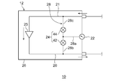
図2は、実施の形態に係る作動ガスの物理量測定系の一例を概略的に示す図である。この測定系は、図1に示される圧縮機12またはその他の極低温冷凍機10の圧縮機に適用可能である。
図2に示されるように、切替機構24は、測定器流路28に設けられた一組のオンオフ弁、具体的には第1オンオフ弁42と第2オンオフ弁44を備えてもよい。第1オンオフ弁42は、高圧導入路28bに設けられ、第2オンオフ弁44は、低圧導入路28cに設けられている。より具体的に言えば、第1オンオフ弁42は、測定器接続路28a、高圧導入路28b、低圧導入路28cの合流点の片側に配置され、第2オンオフ弁44は、この合流点の反対側に配置されている。これらオンオフ弁は、例えば電磁弁、いわゆるソレノイドバルブである。オンオフ弁は、常閉型であってもよい。
切替機構24の第1状態においては、第1オンオフ弁42が開(オン)とされ、第2オンオフ弁44が閉(オフ)とされる。これにより、高圧流路20から高圧導入路28b、切替機構24、および測定器接続路28aを通じて測定器22へと高圧の作動ガスが導入される。切替機構24の第2状態においては、第1オンオフ弁42が閉(オフ)とされ、第2オンオフ弁44が開(オン)とされる。これにより、低圧流路21から低圧導入路28c、切替機構24、および測定器接続路28aを通じて測定器22へと低圧の作動ガスが導入される。なお第1オンオフ弁42と第2オンオフ弁44は同時に開かれることはない。
このような構成を採用しても、切替機構24を切り替えることにより、測定器22を使用して圧縮機12の高圧側(吐出側)と低圧側(吸入側)の圧力を測定することができる。
また、切替機構24は、測定器22の非測定時に第3状態をとるように構成されていてもよい。切替機構24の第3状態においては、第1オンオフ弁42と第2オンオフ弁44は同時に閉鎖される。このようにすれば、膨張機14の動作に伴う作動ガス圧力変動による物理量測定系への影響を低減し、測定器22の劣化を抑制することができる。
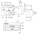
図3は、実施の形態に係る作動ガスの物理量測定系の一例を概略的に示す図である。この測定系は、図1に示される圧縮機12またはその他の極低温冷凍機10の圧縮機に適用可能である。
図3に示されるように、圧縮機12は、切替機構24を制御する切替制御部46と、記憶部48とを備えてもよい。切替制御部46および記憶部48は、極低温冷凍機10を制御する制御装置50の一部を構成していてもよい。切替制御部46は、切替指令信号S1を切替機構24に送信することができるように切替機構24に通信可能に接続されている。切替指令信号S1は、切替機構24がとるべき状態を表す情報を含む。すなわち、高圧側の物理量を測定すべき場合には、切替制御部46は、第1状態を表す切替指令信号S1を生成し切替機構24に送信する。低圧側の物理量を測定すべき場合には、切替制御部46は、第2状態を表す切替指令信号S1を生成し切替機構24に送信する。切替機構24が第3状態をとることができる場合には、切替制御部46は、測定器22の非測定時に、第3状態を表す切替指令信号S1を生成し切替機構24に送信してもよい。切替機構24は、切替指令信号S1を受信すると、切替指令信号S1に従って第1状態または第2状態(または第3状態)のいずれかに切り替わるように動作する。
また、測定器22は、測定値を表す測定信号S2を出力するように構成されている。切替制御部46は、測定信号S2を取得するように測定器22と電気的に接続されている。切替制御部46は、切替機構24が第1状態にあるとき取得された測定値を高圧側の物理量として記憶部48に保存し、切替機構24が第2状態にあるとき取得された測定値を低圧側の物理量として記憶部48に保存する。言い換えれば、切替制御部46は、第1状態を表す切替指令信号S1に応答して受信された測定信号S2を高圧側の物理量として記憶部48に保存し、第2状態を表す切替指令信号S1に応答して受信された測定信号S2を低圧側の物理量として記憶部48に保存する。なお、第3状態において受信された測定信号S2は、高圧側の物理量でも低圧側の物理量でもなく、有効な物理量を表さないので、記憶部48に保存する必要はない。
切替制御部46は、一定時間ごとに切替指令信号S1を第1状態と第2状態に切り替えてもよい。このようにすれば、高圧側の物理量と低圧側の物理量を交互に自動的に測定することができる。また、切替制御部46は、制御装置50またはユーザからの入力を受けて、切替指令信号S1を第1状態と第2状態に切り替えてもよい。このようにすれば、制御装置50またはユーザからの要求に応じて高圧側の物理量と低圧側の物理量を切り替えて測定することができる。
また、切替制御部46は、切替指令信号S1を第1状態と第2状態を切り替えるときに、第1状態と第2状態の間に第3状態を含めてもよい。この場合、切替制御部46は、切替指令信号S1を第1状態から第3状態に切り替え、その後第2状態に切り替えてもよい。同様に、切替制御部46は、切替指令信号S1を第2状態から第3状態に切り替え、その後第1状態に切り替えてもよい。
切替制御部46は、膨張機14の動作周期と同期した測定周期で物理量測定系(すなわち測定器22および切替機構24)を動作させてもよい。切替制御部46は、第1状態が選択されている間におけるある特定の第1タイミング(または第1位相)で作動ガスの物理量を測定するように物理量測定系を制御してもよい。同様に、切替制御部46は、第2状態が選択されている間におけるある特定の第2タイミング(または第2位相)で作動ガスの物理量を測定するように物理量測定系を制御してもよい。このようにすれば、高圧側と低圧側それぞれにおける毎回の物理量測定を圧力の脈動に関して共通の条件で行うことができ、圧力の脈動に起因する物理量測定のノイズを抑制することができる。
制御装置50(すなわち切替制御部46および記憶部48)は、ハードウェア構成としてはコンピュータのCPUやメモリをはじめとする素子や回路で実現され、ソフトウェア構成としてはコンピュータプログラム等によって実現されるが、図3では適宜、それらの連携によって実現される機能ブロックとして描いている。これらの機能ブロックはハードウェア、ソフトウェアの組合せによっていろいろなかたちで実現できることは、当業者には理解されるところである。
以上、本発明を実施例にもとづいて説明した。本発明は上記実施形態に限定されず、種々の設計変更が可能であり、様々な変形例が可能であること、またそうした変形例も本発明の範囲にあることは、当業者に理解されるところである。
ある実施の形態に関連して説明した種々の特徴は、他の実施の形態にも適用可能である。組合せによって生じる新たな実施の形態は、組み合わされる実施の形態それぞれの効果をあわせもつ。
上述の実施の形態では、測定器22は、作動ガスの物理量として圧力を測定するように構成されているが、本発明はこれには限定されない。測定器22は、作動ガスの温度、流量、またはそのほかの物理量を測定するように構成されていてもよい。
上述の実施の形態では、切替機構24が三方弁である場合、三方弁が第1状態と第2状態と第3状態を切り替えるように構成されているが、本発明はこれには限定されない。三方弁は、第1状態と第2状態にのみ切り替えるように構成されていてもよい。この場合、切替機構24は、三方弁に加えて、測定器接続路28aに設けられた追加のオンオフ弁を有してもよい。第1状態と第2状態においてはオンオフ弁を開くことにより作動ガスを測定器22に導入することができる。第3状態においてはオンオフ弁を閉じることにより測定器22を高圧流路20と低圧流路21の両方から切り離すことができる。
本発明は、極低温冷凍機の圧縮機における利用が可能である。
10 極低温冷凍機、 12 圧縮機、 14 膨張機、 20 高圧流路、 21 低圧流路、 22 測定器、 24 切替機構。
Claims (5)
- 極低温冷凍機の圧縮機であって、
前記極低温冷凍機の膨張機に供給される高圧のヘリウムガスが流れる高圧流路と、
前記極低温冷凍機の膨張機から回収される低圧のヘリウムガスが流れる低圧流路と、
前記ヘリウムガスの物理量を測定する測定器と、
前記測定器に前記高圧流路と前記低圧流路のうちいずれかを選択的に接続する切替機構と、を備えることを特徴とする極低温冷凍機の圧縮機。 - 前記測定器は、前記ヘリウムガスの圧力を測定することを特徴とする請求項1に記載の極低温冷凍機の圧縮機。
- 前記切替機構は、前記測定器の非測定時に前記測定器を前記高圧流路と前記低圧流路の両方から切り離すことを特徴とする請求項1または2に記載の極低温冷凍機の圧縮機。
- 前記圧縮機は、前記切替機構が設けられ、前記測定器を前記高圧流路と前記低圧流路に接続する測定器流路を備え、
前記測定器は、前記測定器流路に設けられた唯一の測定器であることを特徴とする請求項1から3のいずれかに記載の極低温冷凍機の圧縮機。 - 前記測定器は、前記極低温冷凍機の膨張機の動作周期と同期した測定周期で前記ヘリウムガスの物理量を測定することを特徴とする請求項1から4のいずれかに記載の極低温冷凍機の圧縮機。
Applications Claiming Priority (2)
| Application Number | Priority Date | Filing Date | Title |
|---|---|---|---|
| JP2018-126915 | 2018-07-03 | ||
| JP2018126915A JP2020008180A (ja) | 2018-07-03 | 2018-07-03 | 極低温冷凍機の圧縮機 |
Publications (1)
| Publication Number | Publication Date |
|---|---|
| WO2020009110A1 true WO2020009110A1 (ja) | 2020-01-09 |
Family
ID=69060379
Family Applications (1)
| Application Number | Title | Priority Date | Filing Date |
|---|---|---|---|
| PCT/JP2019/026295 Ceased WO2020009110A1 (ja) | 2018-07-03 | 2019-07-02 | 極低温冷凍機の圧縮機 |
Country Status (2)
| Country | Link |
|---|---|
| JP (1) | JP2020008180A (ja) |
| WO (1) | WO2020009110A1 (ja) |
Families Citing this family (1)
| Publication number | Priority date | Publication date | Assignee | Title |
|---|---|---|---|---|
| KR102373686B1 (ko) * | 2020-12-23 | 2022-03-15 | 주식회사 헥사 | 수소의 예냉기모듈 및 이를 포함하는 수소액화기 |
Citations (9)
| Publication number | Priority date | Publication date | Assignee | Title |
|---|---|---|---|---|
| JPS60171359A (ja) * | 1984-02-16 | 1985-09-04 | ダイキン工業株式会社 | 極低温冷凍機 |
| JPH0234963U (ja) * | 1988-08-31 | 1990-03-06 | ||
| JPH0428978A (ja) * | 1990-05-23 | 1992-01-31 | Daikin Ind Ltd | 空気調和装置の圧力検出装置 |
| JPH0618108A (ja) * | 1992-06-30 | 1994-01-25 | Sanyo Electric Co Ltd | 極低温冷凍装置 |
| JPH10110846A (ja) * | 1996-10-03 | 1998-04-28 | Ippei Torigoe | 容器切替式流体素子 |
| JP2004085048A (ja) * | 2002-08-26 | 2004-03-18 | Sumitomo Heavy Ind Ltd | 極低温冷凍装置、及び、その運転方法 |
| JP2005083214A (ja) * | 2003-09-05 | 2005-03-31 | Daikin Ind Ltd | 圧縮機ユニット |
| JP2013242112A (ja) * | 2012-05-22 | 2013-12-05 | Sumitomo Heavy Ind Ltd | 冷却システム及びメンテナンス時期判定方法 |
| JP2015178910A (ja) * | 2014-03-18 | 2015-10-08 | 住友重機械工業株式会社 | 極低温冷凍機および極低温冷凍機の制御方法 |
-
2018
- 2018-07-03 JP JP2018126915A patent/JP2020008180A/ja active Pending
-
2019
- 2019-07-02 WO PCT/JP2019/026295 patent/WO2020009110A1/ja not_active Ceased
Patent Citations (9)
| Publication number | Priority date | Publication date | Assignee | Title |
|---|---|---|---|---|
| JPS60171359A (ja) * | 1984-02-16 | 1985-09-04 | ダイキン工業株式会社 | 極低温冷凍機 |
| JPH0234963U (ja) * | 1988-08-31 | 1990-03-06 | ||
| JPH0428978A (ja) * | 1990-05-23 | 1992-01-31 | Daikin Ind Ltd | 空気調和装置の圧力検出装置 |
| JPH0618108A (ja) * | 1992-06-30 | 1994-01-25 | Sanyo Electric Co Ltd | 極低温冷凍装置 |
| JPH10110846A (ja) * | 1996-10-03 | 1998-04-28 | Ippei Torigoe | 容器切替式流体素子 |
| JP2004085048A (ja) * | 2002-08-26 | 2004-03-18 | Sumitomo Heavy Ind Ltd | 極低温冷凍装置、及び、その運転方法 |
| JP2005083214A (ja) * | 2003-09-05 | 2005-03-31 | Daikin Ind Ltd | 圧縮機ユニット |
| JP2013242112A (ja) * | 2012-05-22 | 2013-12-05 | Sumitomo Heavy Ind Ltd | 冷却システム及びメンテナンス時期判定方法 |
| JP2015178910A (ja) * | 2014-03-18 | 2015-10-08 | 住友重機械工業株式会社 | 極低温冷凍機および極低温冷凍機の制御方法 |
Also Published As
| Publication number | Publication date |
|---|---|
| JP2020008180A (ja) | 2020-01-16 |
Similar Documents
| Publication | Publication Date | Title |
|---|---|---|
| US9797637B2 (en) | Refrigeration cycle apparatus | |
| US10280913B2 (en) | Cryopump system, method of operating the same, and compressor unit | |
| US8336318B2 (en) | Cryopump and method for diagnosing the cryopump | |
| CN100439819C (zh) | 极低温冷冻机 | |
| JP7201447B2 (ja) | 極低温冷凍機の起動方法 | |
| US9470436B2 (en) | Cryogenic refrigeration apparatus and method of controlling cryogenic refrigeration apparatus | |
| US11156387B2 (en) | Cryocooler and control device of cryocooler | |
| WO2019163742A1 (ja) | 極低温冷凍機 | |
| CN104343664A (zh) | 压缩机及冷却系统 | |
| JP2020008180A (ja) | 極低温冷凍機の圧縮機 | |
| WO2017002377A1 (ja) | 冷凍サイクル装置 | |
| WO2021183799A1 (en) | Refrigeration system with flexible high pressure hose assembly | |
| GB2542301A (en) | Air conditioning device | |
| US11649998B2 (en) | Cryocooler | |
| CN111788439A (zh) | 超低温制冷机及超低温制冷机的配管系统 | |
| JP3560497B2 (ja) | 冷凍用圧縮機の試験装置 | |
| CN112334655A (zh) | 低温泵系统及低温泵系统的运转方法 | |
| US2675684A (en) | Refrigerating apparatus | |
| JP7150191B2 (ja) | 室外ユニットおよび冷凍サイクル装置 | |
| WO2026023312A1 (ja) | 極低温冷凍機メンテナンス支援装置、極低温冷凍機メンテナンス支援方法、および極低温冷凍機 | |
| KR100723029B1 (ko) | 냉동기기 제어용 디지털 다중 압력스위치 | |
| CN112503787A (zh) | 制冷剂供液系统 | |
| BRPI1101972A2 (pt) | sistema de sucÇço para compressor de fluidos | |
| KR0128676B1 (ko) | 캐필러리관의 압력측정장치 | |
| JPS6029555A (ja) | 2シリンダ回転式圧縮機の冷凍サイクル |
Legal Events
| Date | Code | Title | Description |
|---|---|---|---|
| 121 | Ep: the epo has been informed by wipo that ep was designated in this application |
Ref document number: 19831266 Country of ref document: EP Kind code of ref document: A1 |
|
| NENP | Non-entry into the national phase |
Ref country code: DE |
|
| 122 | Ep: pct application non-entry in european phase |
Ref document number: 19831266 Country of ref document: EP Kind code of ref document: A1 |