WO2020009050A1 - 擬似力覚呈示装置 - Google Patents
擬似力覚呈示装置 Download PDFInfo
- Publication number
- WO2020009050A1 WO2020009050A1 PCT/JP2019/026025 JP2019026025W WO2020009050A1 WO 2020009050 A1 WO2020009050 A1 WO 2020009050A1 JP 2019026025 W JP2019026025 W JP 2019026025W WO 2020009050 A1 WO2020009050 A1 WO 2020009050A1
- Authority
- WO
- WIPO (PCT)
- Prior art keywords
- pseudo force
- force sense
- pseudo
- physical quantity
- presentation device
- Prior art date
- Legal status (The legal status is an assumption and is not a legal conclusion. Google has not performed a legal analysis and makes no representation as to the accuracy of the status listed.)
- Ceased
Links
Images









Classifications
-
- G—PHYSICS
- G01—MEASURING; TESTING
- G01S—RADIO DIRECTION-FINDING; RADIO NAVIGATION; DETERMINING DISTANCE OR VELOCITY BY USE OF RADIO WAVES; LOCATING OR PRESENCE-DETECTING BY USE OF THE REFLECTION OR RERADIATION OF RADIO WAVES; ANALOGOUS ARRANGEMENTS USING OTHER WAVES
- G01S13/00—Systems using the reflection or reradiation of radio waves, e.g. radar systems; Analogous systems using reflection or reradiation of waves whose nature or wavelength is irrelevant or unspecified
- G01S13/88—Radar or analogous systems specially adapted for specific applications
-
- G—PHYSICS
- G01—MEASURING; TESTING
- G01S—RADIO DIRECTION-FINDING; RADIO NAVIGATION; DETERMINING DISTANCE OR VELOCITY BY USE OF RADIO WAVES; LOCATING OR PRESENCE-DETECTING BY USE OF THE REFLECTION OR RERADIATION OF RADIO WAVES; ANALOGOUS ARRANGEMENTS USING OTHER WAVES
- G01S13/00—Systems using the reflection or reradiation of radio waves, e.g. radar systems; Analogous systems using reflection or reradiation of waves whose nature or wavelength is irrelevant or unspecified
- G01S13/02—Systems using reflection of radio waves, e.g. primary radar systems; Analogous systems
- G01S13/06—Systems determining position data of a target
- G01S13/08—Systems for measuring distance only
-
- G—PHYSICS
- G06—COMPUTING OR CALCULATING; COUNTING
- G06F—ELECTRIC DIGITAL DATA PROCESSING
- G06F3/00—Input arrangements for transferring data to be processed into a form capable of being handled by the computer; Output arrangements for transferring data from processing unit to output unit, e.g. interface arrangements
- G06F3/01—Input arrangements or combined input and output arrangements for interaction between user and computer
-
- G—PHYSICS
- G08—SIGNALLING
- G08B—SIGNALLING SYSTEMS, e.g. PERSONAL CALLING SYSTEMS; ORDER TELEGRAPHS; ALARM SYSTEMS
- G08B6/00—Tactile signalling systems, e.g. tactile personal calling systems
Definitions
- the present invention relates to a technique for presenting a pseudo force sensation.
- a blind person touches an external object (hereinafter referred to as an “external object”) with a white stick or his / her own hand to know the existence, position, shape, etc. of the external object and avoid obstacles, etc. Often do.
- contact is not an effective means for fragile objects, objects that should not be touched, and the location of others in walking or vehicles. Also, you can only touch objects within reach of your hand or white cane.
- the present invention has been made in view of such a point, and an object of the present invention is to provide a technique for presenting a pseudo force sense according to an external object without touching the external object.
- a pseudo force sense presentation device having a force sense presentation mechanism for presenting a pseudo force sense.
- FIG. 1 is a block diagram illustrating a pseudo force sensation presentation device according to an embodiment.
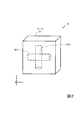
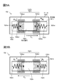
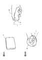
- FIG. 2 is a conceptual diagram illustrating the force sense presentation mechanism of FIG. 3A and 3B are conceptual diagrams illustrating the asymmetrical motion unit of FIG. 4A and 4B are conceptual diagrams illustrating the use state of the pseudo force sensation presentation device according to the embodiment.
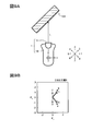
- 5A and 5B are conceptual diagrams for explaining the operation of the pseudo force sensation presentation device according to the embodiment.
- 6A and 6B are conceptual diagrams for explaining the operation of the pseudo force sensation providing apparatus according to the embodiment.
- 7A and 7B are conceptual diagrams for explaining the operation of the pseudo force sensation presentation device according to the embodiment.
- 8A and 8B are conceptual diagrams for explaining the operation of the pseudo force sensation presentation device according to the embodiment.
- 9A and 9B are conceptual diagrams for explaining the operation of the pseudo force sensation presentation device according to the embodiment.
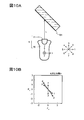
- 10A to 10D are conceptual diagrams for explaining the operation of the pseudo force sensation presentation device according to the embodiment.
- 11A to 11D are conceptual diagrams for explaining the operation of the pseudo force sensation presentation device according to the embodiment.
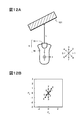
- 12A to 12D are conceptual diagrams for explaining the operation of the pseudo force sensation presentation device according to the embodiment.
- 13A to 13D are conceptual diagrams for explaining the operation of the pseudo force sensation providing apparatus according to the embodiment.
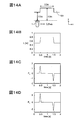
- 14A to 14D are conceptual diagrams for explaining the operation of the pseudo force sensation providing device of the embodiment.
- 15A to 15D are conceptual diagrams for explaining the operation of the pseudo force sensation providing device according to the embodiment.
- 16A and 16B are conceptual diagrams for explaining the operation of the pseudo force sensation presentation device according to the embodiment.
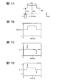
- 17A and 17B are conceptual diagrams for explaining the operation of the pseudo force sensation providing apparatus according to the embodiment.
- 18A and 18B are conceptual diagrams for explaining the operation of the pseudo force sensation providing apparatus according to the embodiment.
- 19A and 19B are conceptual diagrams for explaining the operation of the pseudo force sensation presentation device according to the embodiment.
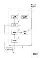
- FIG. 20 is a block diagram illustrating the pseudo force sensation presentation device according to the embodiment.
- the pseudo force sense presentation device 1 of the present embodiment includes a distance measurement unit 11, a position / posture measurement unit 12, a calculation unit 13, a control unit 14, a force sense presentation mechanism 15, and a case 16.
- a distance measurement unit 11 As illustrated in FIG. 1, the pseudo force sense presentation device 1 of the present embodiment includes a distance measurement unit 11, a position / posture measurement unit 12, a calculation unit 13, a control unit 14, a force sense presentation mechanism 15, and a case 16.
- the distance measuring unit 11 is a well-known sensor that measures the distance from the pseudo force sensation presentation device 1 to the external object in a non-contact manner.
- a sensor that measures distance using laser light, infrared light, ultrasonic waves, millimeter waves, or the like can be used as the distance measurement unit 11.
- the position / posture measurement unit 12 is a sensor that measures at least one of the movement and the posture of the pseudo force sensation presentation device 1.
- the position / orientation measurement unit 12 includes a GPS sensor, a magnetic sensor, an acceleration sensor (for example, a three-axis translational acceleration sensor), a gyro sensor (for example, 3) for measuring a position, a speed, an acceleration, a direction, an angular velocity, an angular acceleration, and the like. Shaft gyro sensor).
- the arithmetic unit 13 and the control unit 14 include, for example, a general-purpose or a general-purpose processor including a processor (hardware processor) such as a CPU (central processing unit) and a memory such as a RAM (random-access memory) and a ROM (read-only memory). It is an apparatus configured by executing a predetermined program by a dedicated computer.
- This computer may include one processor or memory, or may include a plurality of processors or memories.
- This program may be installed in a computer, or may be recorded in a ROM or the like in advance.
- Some or all of the processing units are configured using an electronic circuit that realizes a processing function without using a program, instead of an electronic circuit (circuitry) that realizes a functional configuration by reading a program like a CPU. You may. Further, an electronic circuit constituting one device may include a plurality of CPUs.
- the force sense presentation mechanism 15 of the present embodiment is attached to the base 151 and the base 151, and presents a pseudo force sense (that is, a force sense in the translation direction) in the x-axis direction. It has an asymmetrical movement unit 152-1 and an asymmetrical movement unit 152-2 attached to the base 151 and presenting a pseudo force sense (that is, a force sense in the translation direction) in the y-axis direction.
- the x-axis and the y-axis are axes in a rectangular coordinate system (a rectangular coordinate system including an x-axis, a y-axis, and a z-axis) fixed to the base 151.
- the asymmetric movement units 152-1 and 152-2 are arranged so as to overlap each other so as to form a cross. By controlling the driving of these asymmetrical motion units 152-1 and 152-2, it is possible to present a pseudo force sense in an arbitrary direction on the xy plane.
- the asymmetric movement units 152-1 and 152-2 are devices that present a pseudo force sensation based on asymmetric movement (periodic asymmetric movement, for example, asymmetric vibration).
- examples of the asymmetric motion include an asymmetric acceleration motion, an asymmetric speed motion, and an asymmetric amplitude motion.
- “Pseudo force sense” refers to the perception that as if a force is not continuously applied in a specific direction from an object, but as if the force continues to be applied in this specific direction. means.
- Examples of the asymmetric movement units 152-1 and 152-2 are described in, for example, Patent Documents 2 and 3, Non-Patent Document 1, and the like.
- the fact that a pseudo force sense can be presented in an arbitrary direction by a combination of the asymmetrical motion units 152-1 and 152-2 is disclosed in, for example, Reference 1 (Japanese Patent Application Laid-Open No. 2015-225520) and Reference 2 (Japanese Patent Application Laid-Open No. 2017-208905).
- the case 16 is a hollow member.
- the case 16 is made of, for example, synthetic resin, metal, glass, wood, rubber, or the like.
- a distance measurement unit 11, a position / posture measurement unit 12, a calculation unit 13, a control unit 14, and a base 151 of a force sense presentation mechanism 15 are fixed inside the case 16.
- the asymmetric motion unit 152-i (vibrator or actuator) includes a support unit 1521-i, springs 1522-i and 1523-i, a coil 1524-i, and a permanent magnet 1525.
- the case 1526-i and the supporting portion 1521-i are both hollow members having a shape in which both open ends of a cylinder are closed.
- the support portion 1521-i is smaller than the case 1526-i, and has a size that can be accommodated inside the case 1526-i.
- the case 1526-i and the support 1521-i are made of, for example, a synthetic resin such as an ABS resin.
- the springs 1522-i and 1523-i are, for example, a helical spring or a leaf spring made of metal or the like. It is desirable that the springs 1522-i and 1523-i have the same spring constant, but they may be different from each other.
- the permanent magnet 1525-i is, for example, a columnar permanent magnet. One end 1525a-i side in the longitudinal direction is an N pole, and the other end 1525b-i side is an S pole.
- the coil 1524-i is, for example, a continuous enameled wire and has a first winding portion 1524a-i and a second winding portion 1524b-i.
- the permanent magnet 1525-i is housed inside the support part 1521-i, where it is slidably supported in the longitudinal direction.
- a straight rail is provided on the inner wall surface of the support portion 1521-i along the longitudinal direction, and the rail is slidably supported on the side surface of the permanent magnet 1525-i.
- a rail support portion is provided.
- One end of a spring 1522-i is fixed to the inner wall surface 1521a-i on one end side in the longitudinal direction of the support portion 1521-i, and the other end of the spring 1522-i is connected to the end 1525a-i of the permanent magnet 1525-i. Fixed.
- one end of a spring 1523-i is fixed to an inner wall surface 1521b-i on the other end side in the longitudinal direction of the support portion 1521-i, and the other end of the spring 1523-i is connected to an end 1525b of a permanent magnet 1525-i. -Fixed to i.
- a coil 1524-i is wound around the outer periphery of the support portion 1521-i.
- the permanent magnet 1525-i end 1525a-i side of the (N pole side), the first winding portion 1524a-i are wound in A 1 direction
- the end portion 1525b-i side (S-pole side) in the second winding section 1524b-i is wound around the a 1 direction (direction toward the back to the front) in the opposite direction to the direction of B 1 direction (direction toward the front to the back). That is, when viewed from the end 1525a-i side (N pole side) of the permanent magnet 1525-i, the first winding part 1524a-i is wound clockwise
- the second winding part 1524bi is counterclockwise.
- the end 1525a-i side (N-pole side) of the permanent magnet 1525-i is turned by the first winding. It is desirable that the end 1525b-i side (S-pole side) be disposed in the region of the second winding portion 1524bi.
- the support portion 1521-i, the springs 1522-i, 1523-i, the coil 1524-i, and the permanent magnet 1525-i arranged and configured as described above are housed in the case 1526-i, and the support portion 1521-i is provided. Are fixed inside the case 1526-i. However, the longitudinal direction of the case 1526-i matches the longitudinal direction of the support 1521-i and the longitudinal direction of the permanent magnet 1525-i.
- a period (time) in which a current flows through the coil 1524-i in a predetermined direction and other periods are periodically repeated.
- the ratio (reversal ratio) between the period in which the current flows in the predetermined direction and the other period (reversal ratio) is biased to one of the periods, so that the permanent magnet 1525-i is moved asymmetrically (asymmetrically vibrated).
- Pseudo force sense can be presented in the direction of. This is a current that periodically repeats a period in which a current flows in a predetermined direction and a period other than that, and a reversal ratio between a period in which a current flows in a predetermined direction and a period other than that is biased to one of the periods.
- a pseudo force sense can be presented in the leftward or rightward direction in FIG. 3B.
- a pseudo force sensation is presented in the leftward direction in FIGS. 3A and 3B
- a periodic current having a reversal ratio satisfying t 1 > t 2 is supplied to the coil 1524-i.
- a periodic current having a reversal ratio satisfying t 1 ⁇ t 2 is supplied to the coil 1524-i.
- the direction of the pseudo force sense is the direction of the force sense recognized by humans.
- the direction of the pseudo force sense is specified by a function value for a period in which a current flows in a predetermined direction and a period other than the period.
- the drive frequency, inversion ratio, and peak value of a drive signal for example, a drive current flowing through the coil 1524-i or a drive voltage applied to the coil 1524-i
- the magnitude of the pseudo force sense presented is controlled.
- the magnitude of the force sensation is reduced (for example, see Patent Document 2).
- the magnitude of the pseudo force sense is the force sense recognized by a human.
- the magnitude of the pseudo force sensation can be represented by at least one of the function values of the drive frequency, the inversion ratio, and the peak value (for example, a proportional function, an Nth-order proportional function, an exponential proportional function, a sigmoid function, and the like).
- the magnitude of the force sense perceived by a human is not always proportional to the drive frequency, the reversal ratio, the peak value, and the amplitude of the permanent magnet 1525-i, so the magnitude of the pseudo force sense is appropriately presented.
- a threshold value is provided for the input value of such a function, and the input value does not fall within the threshold value.
- the input value may be fixed to the threshold.
- the distance measurement unit 11 measures a distance in the y-axis direction from the pseudo force sensation presentation device 1 to an external object 101 (for example, a wall, a floor, an installed object, an obstacle, a human, etc.), and a physical quantity representing the measurement result.
- P1 for example, measured distance
- first physical quantity is obtained and output.
- the position / posture measuring unit 12 measures at least one of the movement and the posture of the pseudo force sensation presentation device 1 itself, and calculates a physical quantity P2 (for example, position, velocity, acceleration) (second physical quantity) and the posture indicating the movement. At least one of the physical quantity P3 (for example, direction, angular velocity, angular acceleration) (third physical quantity) is obtained and output.
- a physical quantity P2 for example, position, velocity, acceleration
- P3 for example, direction, angular velocity, angular acceleration
- the physical quantity P1 obtained by the distance measuring section 11 and at least one of the physical quantity P2 and the physical quantity P3 obtained by the position / posture measuring section 12 are input to the calculating section 13.
- the arithmetic unit 13 uses the input physical quantity, and the asymmetric motion unit 152-i of the force sense presentation mechanism 15 performs an asymmetrical motion according to at least one of the physical quantity and the function value of the physical quantity, and the force sense presentation mechanism 15
- a control signal CS for presenting a pseudo force sense based on the asymmetric movement is obtained and output.
- the control unit 14 generates a drive signal DS (drive current or drive voltage) corresponding to the control signal CS obtained by the calculation unit 13 and supplies the drive signal DS to the coil 1524-i of the asymmetric movement unit 152-i.
- the force sense presentation mechanism 15 determines the physical amount P1 (the first physical amount obtained by measuring the distance from the external object to the pseudo force sense presenting device 1), the function value of the physical amount P1, and the physical amount P2 (pseudo force sense).
- a function of the physical quantity P2 (a second physical quantity obtained by measuring the motion of the presentation device 1), a function value of the physical quantity P2 (a third physical quantity obtained by measuring the attitude of the pseudo force sense presentation device 1), and a function of the physical quantity P3 Value, and presents a pseudo force sense based on the asymmetric motion.
- the user 100 holding the pseudo force sense presentation device 1 to which the force sense presentation mechanism 15 is attached includes the physical quantity P1, the function value of the physical quantity P1, the physical quantity P2, the function value of the physical quantity P2, the physical quantity P3, the function value of the physical quantity P3, To recognize a pseudo force sense corresponding to at least one of the following.
- specific examples will be described.
- the force sense presentation mechanism 15 performs an asymmetric movement according to the physical amount P1 (the physical amount P1 obtained by measuring the distance in the y direction from the external object 101 to the pseudo force sense presentation device 1).
- P1 the physical amount obtained by measuring the distance in the y direction from the external object 101 to the pseudo force sense presentation device 1.
- the data is input to the operation unit 13.
- the calculation unit 13 generates and outputs a control signal CS for recognizing the following pseudo force sensation F yp .
- F yp k yp (L ⁇ L e ) for 0 ⁇ L ⁇ L max (1)
- F yp F yp max for L ⁇ L max (2)
- k yp is a positive gain constant.
- Le is a predetermined positive reference distance.
- the direction of the pseudo force sense F yp is the y-axis direction.
- a pseudo force sense F yp in the direction from the pseudo force sense presentation device 1 toward the external object 101 is represented by a positive value, and conversely, a pseudo force sense in the direction from the external object 101 toward the pseudo force sense presentation device 1.
- F yp is represented by a negative value.
- F yp max represents the maximum value of F yp .
- the direction and the magnitude of the pseudo force sense can be controlled by the driving frequency, the inversion ratio, the peak value, and the like of the driving signal DS (for example, see Patent Documents 2 and 3).
- the drive signal DS corresponding to the force sensation F yp can be specified, and the control signal CS corresponding to the drive signal DS can be calculated.
- a simulation may be performed with a desired pseudo force sensation F yp as a target value, and a control signal CS for presenting the pseudo force sensation F yp may be set.
- the drive signal DS corresponding to the control signal CS is supplied to the force sense presentation mechanism 15, the user 100 recognizes the following pseudo force sense.
- the distance between the pseudo force sense presenting device 1 and the outside world object 101 L is smaller, the greater the force, the greater the force from the external object 101 side.
- the outside world object 101 side pseudo force sense presenting apparatus 1 is in the maximum force F yp max Recognize a simulated force sensation that is pulled back to
- a pseudo force sense presenting device 1 is disposed in a position spaced by reference distance L e from outside the object 101 is induced by the user 100.
- F yp k yp (L ⁇ L e ) for 0 ⁇ L ⁇ L e (3)
- F yp 0 for L ⁇ L e (4)
- the drive signal DS corresponding to the control signal CS is supplied to the force sense presentation mechanism 15, the user 100 recognizes the following pseudo force sense.
- the user 100 if the distance L from the outside world object 101 to pseudo force sense presenting device 1 is below the reference distance L e, the user 100 has a smaller distance L from the pseudo-force sense presenting apparatus 1 to ambient object 101 A pseudo force sensation that is pushed back from the external object 101 with a relatively large force is recognized.
- the distance L from the outside world object 101 to pseudo force sense presenting apparatus 1 exceeds the reference distance L e, the user 100 does not recognize the pseudo haptic.
- that distance L from the outside world object 101 to pseudo force sense presenting apparatus 1 is equal to or less than the reference distance L e, it can be recognized by the user 100.
- a pseudo force sense corresponding to dL / dt is presented.
- the calculation unit 13 generates and outputs a control signal CS for causing the following pseudo force sense Fyv to be recognized.
- F yy kyv (dL / dt) (5)
- kyv is a positive gain constant.
- the direction of the pseudo force sensation F yv is the y-axis direction.
- the pseudo force sense F yv in the direction from the pseudo force sense presentation device 1 toward the external object 101 is represented by a positive value, and conversely, the pseudo force sense in the direction from the external object 101 toward the pseudo force sense presentation device 1.
- F yv is represented by a negative value.
- t represents time.
- dL / dt is a time differential value of L with respect to t (that is, a time change of the distance L).
- the time differential value can be calculated using, for example, a difference method.
- the user 100 increases the external force with a larger force as the absolute value of the time change dL / dt of the distance L increases.
- a pseudo force sense as if pushed back from the object 101 is recognized.
- the user 100 increases the external force with a larger force as the absolute value of the time change dL / dt of the distance L increases.
- a pseudo force sense as if pulled back to the object 101 is recognized.
- a pseudo force sense is presented.
- the pseudo force sense is presented only when the motion of the pseudo force sense presentation device 1 in the y-axis direction is small.
- the distance measuring unit 11 measures the distance L in the y-axis direction from the pseudo force sensation providing device 1 to the external object 101
- the position / posture measuring unit 12 measures the distance L on the y axis of the pseudo force sensation presenting device 1.
- the calculation unit 13 generates and outputs a control signal CS for causing the following pseudo force sense Fyv to be recognized.
- F yv kyv (dL / dt) for abs (dy / dt) ⁇ y ′ s (6)
- F yy 0 for abs (dy / dt)> y ′ s (7)
- dy / dt is a time differential value of the position y on the y-axis of the pseudo force sensation presentation device 1 with respect to t (that is, the moving speed of the pseudo force sensation presentation device 1 in the y-axis direction).
- abs ( ⁇ ) represents the absolute value of ⁇ .
- y 's represents a positive predetermined threshold value.
- the direction of the pseudo force sensation F yv is the y-axis direction.
- the pseudo force sense F yv in the direction from the pseudo force sense presentation device 1 toward the external object 101 is represented by a positive value, and conversely, the pseudo force sense in the direction from the external object 101 toward the pseudo force sense presentation device 1.
- F yv is represented by a negative value.
- the distance measurement unit 11 measures the distance L in the y-axis direction from the pseudo force sensation providing device 1 to the external object 101, and the position / posture measurement unit 12 is on the x axis of the pseudo force sensation providing device 1.
- the calculation unit 13 generates and outputs a control signal CS for recognizing the following pseudo force sense Fxv .
- k xv is a positive gain constant.
- the direction of the pseudo force sense F xv is the x-axis direction.
- dx / dt is a time differential value of the x-axis position x of the pseudo force sense presentation device 1 with respect to t (that is, the moving speed of the pseudo force sense presentation device 1 in the x axis direction).
- the direction of the pseudo force sense F xv is the x-axis direction.
- the rightward simulated force Fxv is represented by a positive value
- the leftward simulated force Fxv is represented by a negative value.
- the user 100 perceives a pseudo force sense in a direction in which the value of the x-axis increases (rightward).
- the user 100 perceives a pseudo force sense in a direction in which the value of the x-axis decreases (leftward).
- the pseudo force sense in any direction increases as the absolute value of dL / dt increases, and increases as the absolute value of dx / dt increases.
- the specific example 3-2 is based on the time change dx / dt of the position in the x-axis direction of the pseudo force sensation providing device 1 described in the specific example 3-1 and the angular velocity z z of the pseudo force sensation providing device 1 around the z axis. one that approximates a time variation d [theta] z / dt.
- the specific example 3-2 can simplify the configuration of the pseudo force sensation presentation device 1 as compared with the specific example 3-1.
- the distance measuring unit 11 measures the distance L in the y-axis direction from the pseudo force sensation providing device 1 to the external object 101
- the position / posture measuring unit 12 measures the distance L around the z axis of the pseudo force sensation presenting device 1.
- the data is input to the operation unit 13.
- the calculation unit 13 generates and outputs a control signal CS for recognizing the following pseudo force sense Fxv .
- clockwise FIGS. 5A and when as illustrated in FIGS. 5A and 5B, the angular velocity theta z around the z-axis as viewed in the z-axis direction (direction toward the front from the back of FIGS. 5A and 5B)
- the direction (counterclockwise in 5B) is the positive direction.
- This is an example of presenting a corresponding pseudo force sensation.
- the distance measurement unit 11 measures the distance L in the y-axis direction from the pseudo force sensation providing device 1 to the external object 101, and the position / posture measurement unit 12 is on the x axis of the pseudo force sensation providing device 1.
- the calculation unit 13 generates and outputs a control signal CS for recognizing the following pseudo force sense Fxv .
- the drive signal DS corresponding to the control signal CS is supplied to the force sense presentation mechanism 15, the user 100 recognizes the following pseudo force sense.
- the user 100 perceives a pseudo force sensation in a direction (rightward) in which the value of the x-axis increases.
- dx / dt is negative, the user 100 perceives a pseudo force sense in a direction (leftward) in which the value of the x-axis decreases.
- the pseudo force sense in any direction increases as the absolute value of dL / dt increases, and increases as the absolute value of dx / dt increases.
- the magnitude of the pseudo force sense increases as the pseudo force sense presentation device 1 moves faster in the x-axis direction, and the magnitude of the pseudo force sense increases as the time change of L increases.
- the specific example 3-4 is based on the time change dx / dt of the position in the x-axis direction of the pseudo force sensation providing apparatus 1 described in the specific example 3-3, and the angular velocity z z of the pseudo force sensation presenting apparatus 1 around the z axis. one that approximates a time variation d [theta] z / dt.
- the distance measuring unit 11 measures the distance L in the y-axis direction from the pseudo force sensation providing device 1 to the external object 101
- the position / posture measuring unit 12 measures the distance L around the z axis of the pseudo force sensation presenting device 1.
- the physical quantity P1 L and the physical quantity P2 is input to the arithmetic unit 13.
- the calculation unit 13 generates and outputs a control signal CS for recognizing the following pseudo force sense Fxv .
- a composition of the components of the above-described pseudo force senses F yp and F yv may be presented in the y-axis direction, and the pseudo force sense F xv may be presented in the x-axis direction.
- the arithmetic unit 13 may generate and output a control signal CS for perceived a pseudo force F y and F x, as follows.
- F y F yp + F yv (12)
- F x F xv (13)
- the orientation of the pseudo force F y is the y-axis direction.
- Orientation of the pseudo force F x is the x-axis direction.
- a control signal for causing the pseudo-force which is produced by the non-linear converting the pseudo-force F y and F x of Example 4 recognized the F 'y and F' x CS may be generated and output.
- the calculation unit 13 may generate and output a control signal CS for recognizing pseudo force senses F ′ y and F ′ x which are sigmoid function values of F y and F x as described below.
- k gy1 , k gy2 , k gx1 , and k gx2 are positive gain constants. exp ( ⁇ ) is an exponential function value of ⁇ .
- Orientation of the pseudo force F y is the y-axis direction.
- the pseudo force sense F ′ y in the direction from the pseudo force sense presentation device 1 toward the external object 101 is represented by a positive value, and conversely, the pseudo force in the direction from the external object 101 toward the pseudo force sense presentation device 1.
- the sense F 'y represents a negative value.
- Orientation of the pseudo force F 'x is the x-axis direction. 'Represents a x a positive value, pseudo force F in the left direction' pseudo force F in the right direction in FIGS. 5A and 5B represent the x negative value. This makes it possible to match the pseudo force sense presented with the perceived dynamic range.
- Calculation unit 13 may generate and output a control signal CS for causing recognize pseudo force F 'y represented by a piecewise linear function value F y as follows.
- F 'y F y for -F y max ⁇ F y ⁇ F y max (14)
- F 'y F y max for F y max ⁇ F y (15)
- F ′ y ⁇ F y max for ⁇ F y max ⁇ F y (16)
- F y max is the maximum value of the pseudo force sensation F y .
- the force sense presentation mechanism 15 also measures the physical amount P2 obtained by measuring the motion of the pseudo force sense presentation device 1, the function value of the physical amount P2, and the physical amount P3 obtained by measuring the posture of the pseudo force sense presentation device 1.
- the force sense presentation mechanism 15 may present a combination of at least a part of the pseudo force senses of the modes A to C, or the force sense presentation mechanism 15 may present the pseudo force sense of the modes A to C. (Mode D: specific examples 4-1, 4-2, 5-1, 5-2, 5-3) may be presented.
- Example 1 of relationship between positional relationship and pseudo force sense >> The relationship between the positional relationship between the external object 101 and the pseudo force sense presentation device 1 and the pseudo force sense presented by the pseudo force sense presentation device 1 is illustrated.
- Numerals 1 to 8 in FIGS. 6A, 7A, 8A, and 9A indicate directions in the xy plane. 6B, FIG. 7B, FIG. 8B, and FIG.
- the pseudo force sensation presentation device 1 includes a component in the opposite direction to the y-axis component of the movement direction and the movement direction. 6B (direction components 5, 6, 7 in FIG. 6B, direction components 6, 7, 8 in FIG. 7B, direction components 1, 6, 7, 8 in FIG. 8B, 1, 7 in FIG. 9B). , 8 directional components).
- the pseudo force sensation presentation device 1 moves in a direction in which the distance L to the external object 101 decreases (directions 1, 2, 3 in FIG. 6A, directions 2, 3, 4 in FIG. 7A, FIG. 8A). 2, 3, 4, and 5 directions, and 3, 4, and 5 directions in FIG.
- the pseudo force sensation presentation device 1 calculates The components of the opposite direction (direction components 1, 2, 3 in FIG. 6B, direction components 2, 3, 4 in FIG. 7B, direction components 2, 3, 4, 5 in FIG. 8B, 3, 4, 3 in FIG. 9B) 5 directional components).
- direction components 1, 2, 3 in FIG. 6B, direction components 2, 3, 4 in FIG. 7B, direction components 2, 3, 4, 5 in FIG. 8B, 3, 4, 3 in FIG. 9B 5 directional components.
- Numerals 1 to 8 in FIGS. 10A, 11A, 12A, and 13A represent directions on the xy plane.
- FIGS. 10B, 11B, 12B, and 13B show the above description when the pseudo force sensation presentation device 1 and the external object 101, which is a wall, are in the positional relationships of FIGS.
- pseudo-force sense presenting apparatus 1 in the direction of the indicated the x-y plane by the number 1 to 8 of translating at a unit speed, pseudo force F y and pseudo force sense presenting apparatus 1 is presented the synthesis of F x is obtained by vector representation.
- the external object 101 is stationary.
- Each vector has a number indicating the moving direction of the corresponding pseudo force sensation presentation device 1.
- the pseudo force sensation presentation device 1 regardless of the moving direction of the pseudo force sensation presentation device 1, the pseudo force sensation presentation device 1 generates a pseudo force having a component opposite to the y-axis component in the movement direction and an x-axis component in the movement direction.
- Presents senses When the pseudo force sense presentation device 1 moves in the directions indicated by 4 and 8 in FIG. 10A, the directions indicated by 1 and 5 in FIG. 11A, and the directions indicated by 2 and 6 in FIG. No haptic force is presented.
- FIG. 14B to 14D show that the pseudo force sensation presenting device 1 is moved in the x-axis direction at a speed of 0.25 m / s with respect to the external object 101 having a rectangular cross-section (a depression in the y-axis direction) as shown in FIG. 14A.
- / S the distance [s], the distance L [m] from the pseudo force sensation presentation device 1 to the external object 101, the pseudo force F x , and the pseudo force F y Respectively are illustrated.
- the pseudo force sensation presenting device 1 is drawn to the external object 101 when the pseudo force sensation presenting device 1 approaches the concave.
- F x and F y are presented (F x and F y are both positive).
- the user 100 has a feeling that the pseudo force sensation presentation device 1 falls into the depression of the external object 101 in the y-axis direction and further accelerates in the x-axis direction. This is similar to the feeling of tracing the external object 101 with a hand.
- the pseudo force sensations F x and F y are zero.
- the pseudo force sensation presentation device 1 is pushed out of the external object 101 and pushed in the opposite direction to the traveling direction of the pseudo force sensation presentation device 1. a pseudo force is presented (F x and F y are both negative).
- FIGS. 15B to 15D show that the pseudo-force sensation providing apparatus 1 is moved in the x-axis direction at a speed of 0.25 m / sec with respect to the external object 101 having a wedge-shaped depression (recess in the y-axis direction) as shown in FIG. 15A.
- 16B to 16D show the pseudo force sensation presenting device 1 with respect to the external object 101 having a semicircular depression (recess in the y-axis direction) having a semicircular cross section as shown in FIG. 16A.
- the time [s] the distance L [m] from the pseudo force sensation presentation apparatus 1 to the external object 101
- the pseudo force F x the pseudo force sensation presentation apparatus 1
- the pseudo force F x the pseudo force sensation presentation apparatus 1
- the relationship with y is illustrated.
- the positive force sensation F from when the pseudo force sensation presenting device 1 reaches the recess to the position facing the deepest portion of the recess is reached.
- x and Fy are continuously presented.
- the negative pseudo force senses F x and F y are continuously presented until the pseudo force sense presentation device 1 reaches the end of the depression.
- the distance L changes continuously when the cross-sectional shape is a semicircular depression, the magnitudes of the pseudo force senses F x and F y change continuously.
- pseudo force F x, by F y it is possible to recognize the shape of the external object 101 to clear the user 100.
- FIG. 17D show that the pseudo force sensation presentation device 1 is moved at a speed of 0.25 m / s in the x-axis direction with respect to the external object 101 having a rectangular cross-section (a depression in the y-axis direction) as shown in FIG. 17A.
- / S the distance [s], the distance L [m] from the pseudo force sensation presentation device 1 to the external object 101, the pseudo force F x , and the pseudo force F y Respectively are illustrated.
- the pseudo force sensation presenting device 1 is drawn to the external object 101 when the pseudo force sensation presenting device 1 approaches the concave.
- F x and F y are presented (F x and F y are both positive).
- FIGS. 18B to 18D show that the pseudo force sensation presenting device 1 is moved in the x-axis direction at a speed of 0.25 m / sec with respect to the external object 101 having a wedge-shaped depression (a depression in the y-axis direction) as shown in FIG. 18A.
- pseudo force sensation presenting device 1 reaches the position facing the deepest portion of the depression after the pseudo force sensation presentation device 1 reaches the depression, and the positive pseudo force sensation F x , F y is presented continuously. Thereafter, the negative pseudo force senses F x and F y are continuously presented until the pseudo force sense presentation device 1 reaches the end of the depression.
- FIGS. 19B to 19D show the pseudo force sensation presenting apparatus 1 with respect to the external object 101 having a semicircular depression (recess in the y-axis direction) as shown in FIG. 19A.
- the time [s] the distance L [m] from the pseudo force sensation presentation apparatus 1 to the external object 101, the pseudo force F x , and the pseudo force F
- the relationship with y is illustrated.
- the positive force sensation F from when the pseudo force sensation presenting device 1 reaches the recess to the position facing the deepest portion of the recess is reached.
- x and Fy are continuously presented.
- the negative pseudo force senses F x and F y are continuously presented until the pseudo force sense presentation device 1 reaches the end of the depression.
- the magnitudes of the pseudo force senses F x and F y change continuously.
- the components of F yp that depends on the distance L is also included in the F y, pseudo time variation of the force F y in the y-axis direction is more pronounced.
- F y includes a component of F yp depending on the distance L, the user 100 can more clearly recognize the shape of the external object 101.
- a specific mode may be selectable from the plurality of modes A to D described above, or a pseudo force sense presented in each mode may be selectable (for example, the pseudo force sense shown in the above-described specific example equation). Selection from a strong sense of force).
- the type of the pseudo force sense selected in this manner is referred to as a “force sense type”.
- the pseudo force sense presentation device 1 includes a calculation unit 13 ′ having a function of selecting a force sense type, instead of the calculation unit 13.
- the selection information ⁇ indicating a specific haptic type selected from a plurality of haptic types is input to the arithmetic unit 13 ′.
- the operation unit 13 ′ sets the force sense type indicated by the selection information ⁇ , and performs the first implementation of the control signal CS for the force sense presentation mechanism 15 to present a pseudo force sense in the set force sense type. It is obtained and output as described in the embodiment. That is, each of the plurality of force sense types corresponds to physical information including at least one of the physical quantity P1, the function value of the physical quantity P1, the physical quantity P2, the function value of the physical quantity P2, the physical quantity P3, and the function value of the physical quantity P3.
- the force sense presentation mechanism 15 performs an asymmetrical movement according to the physical information corresponding to the selected specific force sense type, and presents a pseudo force sense according to the physical information corresponding to the particular force sense type. I do. This makes it possible to present an appropriate pseudo force sense according to various situations. For example, it is possible to switch the pseudo force sense according to the shape of the external object 101, and to make the user 100 more clearly perceive information on the shape of the external object 101.
- the calculation unit 13 ′ is determined according to information (for example, time, direction, speed, acceleration, and the like) that can be obtained inside the pseudo force sense presentation device 1.
- the selection and setting of the haptic type may be performed inside.
- the second embodiment is a modification of the first embodiment, and the function of the calculation unit 13 is provided outside the pseudo force sensation presentation device.
- the description of the items already described will be simplified using the same reference numerals.
- the pseudo force sense presentation device 2 of the present embodiment includes a distance measurement unit 11, a position / posture measurement unit 12, a control unit 14, a force sense presentation mechanism 15, a case 16, an output unit 26, It has an input unit 27. Further, outside the pseudo force sensation presentation device 2, an arithmetic device 23 capable of performing wireless communication or wired communication with the pseudo force sensation presentation device 2 is provided outside the pseudo force sensation presentation device 2, an arithmetic device 23 capable of performing wireless communication or wired communication with the pseudo force sensation presentation device 2 is provided outside the pseudo force sensation presentation device 2, an arithmetic device 23 capable of performing wireless communication or wired communication with the pseudo force sensation presentation device 2 is provided outside the pseudo force sensation presentation device 2, an arithmetic device 23 capable of performing wireless communication or wired communication with the pseudo force sensation presentation device 2 is provided outside the pseudo force sensation presentation device 2, an arithmetic device 23 capable of performing wireless communication or wired communication with the pseudo force sensation presentation device 2 is provided outside the pseudo force sensation presentation device 2, an arithmetic device 23 capable of performing wireless communication or wire
- Some or all of the processing units are configured using an electronic circuit that realizes a processing function without using a program, instead of an electronic circuit (circuitry) that realizes a functional configuration by reading a program like a CPU. May be.
- An electronic circuit constituting one device may include a plurality of CPUs.
- the operation of the pseudo force sensation presentation device 2 of the second embodiment will be described.
- the differences from the first embodiment are as follows.
- the physical quantity P1 obtained by the distance measuring unit 11 and at least one of the physical quantity P2 and the physical quantity P3 obtained by the position / posture measuring unit 12 are input to the calculation unit 13.
- information representing the physical quantity P1 and / or at least one of the physical quantities P2 and P3 (information representing the measurement value obtained by the measurement unit) is output from the output unit 26, and the arithmetic unit 23 Sent to The arithmetic unit 23 uses the information representing the physical quantity P1, and at least one of the physical quantities P2 and P3 to perform the processing of the arithmetic unit 13 of the first embodiment to obtain the control signal CS (input information corresponding to the measured value). Output.
- the control signal CS is input to the input unit 27 of the pseudo force sensation presentation device 2 and sent to the control unit 14.
- the control unit 14 generates a drive signal DS corresponding to the control signal CS and supplies the drive signal DS to the coil 1524-i of the asymmetric movement unit 152-i.
- the force sense presentation mechanism 15 performs an asymmetrical movement according to the control signal CS, and presents a pseudo force sense based on the asymmetrical movement.
- the pseudo force sense presentation device 2 can be reduced in size.
- the drive signal DS is input to the input unit 27 of the pseudo force sensation presentation device 2, and is supplied to the coil 1524-i of the asymmetric motion unit 152-i.
- the force sense presentation mechanism 15 performs an asymmetrical movement according to the control signal CS, and presents a pseudo force sense based on the asymmetrical movement.
- the pseudo force sensation presentation device 2 can be further miniaturized.
- the arithmetic unit 23 may have the function of the arithmetic unit 13 ′ described in the first modification of the first embodiment instead of the function of the arithmetic unit 13. .
- the present invention is not limited to the above embodiment.
- the asymmetrical movement part 152-i other asymmetrical parts such as Japanese Patent No. 45551448 (Reference Document 3), International Publication WO2007 / 086426 (Reference Document 4), Japanese Patent Application Laid-Open No. 2015-226388 (Reference Document 5), and the like.
- a device that presents a pseudo force sensation based on the movement may be used.
- the force sense presentation mechanism 15 includes three or more asymmetrical motion units 152-i, and by controlling their driving, not only a pseudo force sense in the translation direction but also a pseudo force sense in the rotational direction. It may be able to be presented (for example, see Reference Document 1).
- the translation direction and the rotation direction may be presented by only one asymmetrical motion unit 152-1 using the asymmetrical motion unit 152-1 having the configuration described in Reference 5.
- the asymmetric motion unit 152-i performs an asymmetric motion, and can present a pseudo force sense having two or more degrees of freedom according to the measurement results. If there is, there is no limitation on the configuration and the number of the asymmetrical motion parts 152-i.
- the function value of the physical quantity P2 may be an angular velocity or an angular acceleration.
- a program describing this processing content can be recorded on a computer-readable recording medium.
- a computer-readable recording medium is a non-transitory recording medium. Examples of such a recording medium are a magnetic recording device, an optical disk, a magneto-optical recording medium, a semiconductor memory, and the like.
- this program is carried out, for example, by selling, transferring, lending, or the like, a portable recording medium such as a DVD or a CD-ROM on which the program is recorded. Further, the program may be stored in a storage device of a server computer, and the program may be distributed by transferring the program from the server computer to another computer via a network.
- the computer that executes such a program first stores, for example, a program recorded on a portable recording medium or a program transferred from a server computer in its own storage device.
- the computer reads a program stored in its own storage device and executes a process according to the read program.
- the computer may read the program directly from the portable recording medium and execute processing according to the program, and further, each time the program is transferred from the server computer to the computer. Alternatively, processing according to the received program may be sequentially performed.
- a visually impaired person or a visually impaired person can know the existence, position, shape, and the like of an external object without touching the external object.
- a fragile external object, an external object that should not be touched, and the presence, position, shape, and the like of another person while walking or in a vehicle can be recognized in a non-contact manner.
Landscapes
- Engineering & Computer Science (AREA)
- Radar, Positioning & Navigation (AREA)
- Remote Sensing (AREA)
- Physics & Mathematics (AREA)
- General Physics & Mathematics (AREA)
- Computer Networks & Wireless Communication (AREA)
- General Engineering & Computer Science (AREA)
- Theoretical Computer Science (AREA)
- Human Computer Interaction (AREA)
- Electromagnetism (AREA)
- User Interface Of Digital Computer (AREA)
- Apparatuses For Generation Of Mechanical Vibrations (AREA)
Abstract
外界対象物に触れることなく、当該外界対象物に応じた疑似的な力覚を呈示する。外界対象物から擬似力覚呈示装置までの距離を計測して得られた第1物理量または第1物理量の関数値に応じた非対称運動を行い、非対称運動に基づいた擬似的な力覚を呈示する。
Description
本発明は、擬似的な力覚を呈示する技術に関する。
目の不自由な人は、白杖または自身の手などで外界の対象物(以下「外界対象物」と呼ぶ)に触れ、外界対象物の存在、位置、形状等を知り、障害物回避等をすることが多い。しかし、壊れやすい物、触れてはいけない物、歩行中や乗り物の中での他人の位置確認などの場合は、接触は有効な手段ではない。また、手や白杖が届く範囲の対象だけしか触れることはできない。
一方、非接触で外界対象物までの距離またはその形状等を計測し、その計測結果に応じて音や振動などの情報を呈示する技術が提案されている(例えば、特許文献1等参照)。しかし、このような技術では、計測結果に応じた疑似的な力覚を呈示することは困難である。
また、制御信号に基づいてアクチュエータを制御し、擬似的な力覚を認知させる技術が提案されている(例えば、特許文献2,3および非特許文献1等参照)。このような技術を用いれば任意の方向に擬似的な力覚を呈示できる。
雨宮智浩,高椋慎也,伊藤翔,五味裕章,"指でつまむと引っ張られる感覚を生み出す装置「ぶるなび3」",2014年,NTT技術ジャーナル,Vol.26,No.9,pp.23-26.
しかしながら、外界対象物に触れることなく、当該外界対象物に応じた疑似的な力覚を呈示する技術は知られていない。
本発明はこのような点に鑑みてなされたものであり、外界対象物に触れることなく、当該外界対象物に応じた疑似的な力覚を呈示する技術を提供することを目的とする。
以上の課題を解決するために、外界対象物から擬似力覚呈示装置までの距離を計測して得られた第1物理量または第1物理量の関数値に応じた非対称運動を行い、非対称運動に基づいた擬似的な力覚を呈示する力覚呈示機構を有する擬似力覚呈示装置が提供される。
以上により、外界対象物に触れることなく、当該外界対象物に応じた疑似的な力覚を呈示できる。
以下、図面を参照して本発明の実施形態を説明する。
[第1実施形態]
まず第1実施形態を説明する。
<構成>
図1に例示するように、本実施形態の擬似力覚呈示装置1は、距離計測部11、位置・姿勢計測部12、演算部13、制御部14、力覚呈示機構15、およびケース16を有する。
[第1実施形態]
まず第1実施形態を説明する。
<構成>
図1に例示するように、本実施形態の擬似力覚呈示装置1は、距離計測部11、位置・姿勢計測部12、演算部13、制御部14、力覚呈示機構15、およびケース16を有する。
距離計測部11は、擬似力覚呈示装置1から外界対象物までの距離を非接触で計測する周知のセンサである。例えば、レーザ光、赤外線、超音波、ミリ波などを利用して距離を計測するセンサを距離計測部11として用いることができる。位置・姿勢計測部12は、擬似力覚呈示装置1の動きおよび姿勢の少なくとも一方を計測するセンサである。例えば、位置・姿勢計測部12は、位置、速度、加速度、向き、角速度、角加速度等を計測するGPSセンサ、磁気センサ、加速度センサ(例えば、3軸並進加速度センサ)、ジャイロセンサ(例えば、3軸ジャイロセンサ)などである。演算部13および制御部14は、例えば、CPU(central processing unit)等のプロセッサ(ハードウェア・プロセッサ)およびRAM(random-access memory)・ROM(read-only memory)等のメモリ等を備える汎用または専用のコンピュータが所定のプログラムを実行することで構成される装置である。このコンピュータは1個のプロセッサやメモリを備えていてもよいし、複数個のプロセッサやメモリを備えていてもよい。このプログラムはコンピュータにインストールされてもよいし、予めROM等に記録されていてもよい。また、CPUのようにプログラムが読み込まれることで機能構成を実現する電子回路(circuitry)ではなく、プログラムを用いることなく処理機能を実現する電子回路を用いて一部またはすべての処理部が構成されてもよい。また、1個の装置を構成する電子回路が複数のCPUを含んでいてもよい。
図2に例示するように、本実施形態の力覚呈示機構15は、ベース151と、ベース151に取り付けられ、x軸方向に疑似的な力覚(すなわち、並進方向の力覚)を呈示する非対称運動部152-1と、ベース151に取り付けられ、y軸方向に疑似的な力覚(すなわち、並進方向の力覚)を呈示する非対称運動部152-2とを有する。x軸およびy軸は、ベース151に対して固定された直交座標系(x軸とy軸とz軸とからなる直交座標系)の軸である。本実施形態では、非対称運動部152-1,152-2が互いに十字をなすように重ねて配置される。これらの非対称運動部152-1,152-2の駆動を制御することで、x-y平面の任意の向きに疑似的な力覚を呈示することができる。非対称運動部152-1,152-2は、非対称運動(周期的な非対称運動、例えば、非対称振動)に基づいて擬似的な力覚を呈示する装置である。なお、非対称運動の例は、非対称加速度運動、非対称速度運動、非対称振幅運動などである。「疑似的な力覚」とは、物体から特定の方向に継時的に力を与えられていないにもかかわらず、あたかもこの特定の方向に力を与え続けられているように感じられる知覚を意味する。非対称運動部152-1,152-2の例は、例えば、特許文献2,3および非特許文献1等に記載されている。また、非対称運動部152-1,152-2の組み合わせによって任意の向きに疑似的な力覚を呈示できることは、例えば、参考文献1(特開2015-225520号公報),参考文献2(特開2017-208905)等にも開示されている。
ケース16は中空の部材である。ケース16は、例えば、合成樹脂、金属、ガラス、木材、ゴム等によって構成される。ケース16の内部には、距離計測部11、位置・姿勢計測部12、演算部13、制御部14、および力覚呈示機構15のベース151が固定されている。
≪非対称運動部152-i(ただし、i=1,2)の構成例≫
図3Aおよび図3Bに例示するように、非対称運動部152-i(振動子、アクチュエータ)は、例えば、支持部1521-i、ばね1522-i,1523-i、コイル1524-i、永久磁石1525-i、およびケース1526-iを有している。ケース1526-iおよび支持部1521-iは、ともに円筒の両方の開放端を閉じた形状からなる中空の部材である。ただし、支持部1521-iは、ケース1526-iよりも小さく、ケース1526-iの内部に収容可能な大きさである。ケース1526-iおよび支持部1521-iは、例えば、ABS樹脂等の合成樹脂から構成される。ばね1522-i,1523-iは、例えば、金属等から構成されるつるまきばねや板ばね等である。ばね1522-i,1523-iのばね定数は同一であることが望ましいが、互いに相違していてもよい。永久磁石1525-iは、例えば、円柱形状の永久磁石であり、長手方向の一方の端部1525a-i側がN極であり、他方の端部1525b-i側がS極である。コイル1524-iは、例えば、一つながりのエナメル線であり、第1巻き部1524a-iと第2巻き部1524b-iとを有する。
図3Aおよび図3Bに例示するように、非対称運動部152-i(振動子、アクチュエータ)は、例えば、支持部1521-i、ばね1522-i,1523-i、コイル1524-i、永久磁石1525-i、およびケース1526-iを有している。ケース1526-iおよび支持部1521-iは、ともに円筒の両方の開放端を閉じた形状からなる中空の部材である。ただし、支持部1521-iは、ケース1526-iよりも小さく、ケース1526-iの内部に収容可能な大きさである。ケース1526-iおよび支持部1521-iは、例えば、ABS樹脂等の合成樹脂から構成される。ばね1522-i,1523-iは、例えば、金属等から構成されるつるまきばねや板ばね等である。ばね1522-i,1523-iのばね定数は同一であることが望ましいが、互いに相違していてもよい。永久磁石1525-iは、例えば、円柱形状の永久磁石であり、長手方向の一方の端部1525a-i側がN極であり、他方の端部1525b-i側がS極である。コイル1524-iは、例えば、一つながりのエナメル線であり、第1巻き部1524a-iと第2巻き部1524b-iとを有する。
永久磁石1525-iは支持部1521-iの内部に収容され、そこで長手方向にスライド可能に支持されている。このような支持機構の詳細は図示しないが、例えば、支持部1521-iの内壁面に長手方向に沿ったまっすぐなレールが設けられ、永久磁石1525-iの側面にこのレールをスライド可能に支持するレール支持部が設けられている。支持部1521-iの長手方向の一端側の内壁面1521a-iには、ばね1522-iの一端が固定され、ばね1522-iの他端は永久磁石1525-iの端部1525a-iに固定されている。また、支持部1521-iの長手方向の他端側の内壁面1521b-iには、ばね1523-iの一端が固定され、ばね1523-iの他端は永久磁石1525-iの端部1525b-iに固定されている。
支持部1521-iの外周側にはコイル1524-iが巻きつけられている。ただし、永久磁石1525-iの端部1525a-i側(N極側)では、第1巻き部1524a-iがA1方向に巻きつけられており、端部1525b-i側(S極側)では、第2巻き部1524b-iがA1方向(奥から手前に向けた方向)と反対向きのB1方向(手前から奥に向けた方向)に巻き付けられている。すなわち、永久磁石1525-iの端部1525a-i側(N極側)からみた場合、第1巻き部1524a-iは時計回りに巻き付けられており、第2巻き部1524b-iは反時計回りに巻き付けられている。また、永久磁石1525-iが停止し、ばね1522-i,1523-iからの弾性力が釣り合った状態において、永久磁石1525-iの端部1525a-i側(N極側)が第1巻き部1524a-iの領域に配置され、端部1525b-i側(S極側)が第2巻き部1524b-iの領域に配置されることが望ましい。
以上のように配置構成された支持部1521-i、ばね1522-i,1523-i、コイル1524-i、および永久磁石1525-iが、ケース1526-i内に収容され、支持部1521-iがケース1526-iの内部に固定されている。ただし、ケース1526-iの長手方向は、支持部1521-iの長手方向および永久磁石1525-iの長手方向と一致する。
コイル1524-iにA1方向(B1方向)に電流を流すと、フレミングの左手の法則で説明されるローレンツ力の反作用により、永久磁石1525-iにC1方向(永久磁石1525-iのN極からS極に向かう方向:右方向)の力が加えられる(図3A)。逆に、コイル1524-iにA2方向(B2方向)に電流を流すと、永久磁石1525-iにC2方向(永久磁石1525-iのS極からN極に向かう方向:左方向)の力が加えられる(図3B)。ただし、A2方向はA1方向の反対方向である。これらの動作により、永久磁石1525-iおよびばね1522-i,1523-iからなる系に運動エネルギーが与えられる。それにより、ケース1526-iを基準とする永久磁石1525-iの位置および加速度を変化させることができる。
ここで、コイル1524-iに所定の方向に電流を流す期間(時間)とそれ以外の期間とを周期的に繰り返す。その際、所定の方向に電流を流す期間とそれ以外の期間との比(反転比)を何れか一方の期間に偏らせることにより、永久磁石1525-iを非対称運動(非対称振動)させ、所望の方向に擬似的な力覚を呈示できる。所定の方向に電流を流す期間とそれ以外の期間とを周期的に繰り返す電流であって、所定の方向に電流を流す期間とそれ以外の期間との反転比が何れか一方の期間に偏っているのであれば、どのような波形の電流であってもよい。例えば、A1方向(B1方向)の電流を流す期間t1とA2方向(B2方向)の電流を流す期間t2との比(反転比t1:t2)に応じ、図3Aおよび図3Bの左方向または右方向に擬似的な力覚を呈示できる。図3Aおよび図3Bの左方向に擬似的な力覚を呈示する場合には、t1>t2となる反転比の周期的な電流をコイル1524-iに流す。逆に、右方向に擬似的な力覚を呈示する場合には、t1<t2となる反転比の周期的な電流をコイル1524-iに流す。なお、擬似的な力覚の方向は人間が認知する力覚の方向である。疑似的な力覚の方向は、所定の方向に電流を流す期間とそれ以外の期間とに対する関数値で特定される。また、駆動信号(例えば、コイル1524-iに流す駆動電流やコイル1524-iに加える駆動電圧)の駆動周波数、反転比、ピーク値を制御することで、呈示する擬似的な力覚の大きさを制御できる。例えば、周期的な加速度運動の周波数が80Hzに近くなる駆動周波数であるほど擬似的な力覚の大きさが大きくなり、周期的な加速度運動の周波数が80Hzから遠くなる駆動周波数であるほど擬似的な力覚の大きさが小さくなる(例えば、特許文献2等参照)。また、図3Aおよび図3Bの左方向に擬似的な力覚を呈示する場合、期間t1に対する期間t2の割合が小さいほど、大きな擬似的な力覚を認知させることができる。図3Aおよび図3Bの右方向に擬似的な力覚を呈示する場合、期間t2に対する期間t1の割合が小さいほど、大きな擬似的な力覚を認知させることができる。さらに、図3Aおよび図3Bの左方向に擬似的な力覚を呈示する場合、A2方向(B2方向)へ流される電流のピークが大きいほど、大きな擬似的な力覚を認知させることができる。図3Aおよび図3Bの右方向に擬似的な力覚を呈示する場合、A1方向(B1方向)へ流される電流のピークが大きいほど、大きな擬似的な力覚を認知させることができる。すなわち、永久磁石1525-iの振幅が大きいほど、大きな擬似的な力覚を認知させることができる。なお、擬似的な力覚の大きさは人間が認知する力覚の大きさである。擬似的な力覚の大きさは、駆動周波数、反転比、ピーク値の少なくとも何れかの関数値(例えば、比例関数、N次比例関数、指数的比例関数、シグモイド関数など)で表現できる。なお、人間が認知する力覚の大きさは、駆動周波数、反転比、ピーク値や永久磁石1525-iの振幅に比例するとは限らないため、擬似的な力覚の大きさが適切に呈示されるよう最適な関数を選択する。また、非対称運動部152-iの機械的な構造上、適切に呈示可能な擬似的な力覚の大きさに限界があるため、このような関数の入力値に閾値を設け、閾値に収まらない入力値を当該閾値に固定してもよい。
<動作>
次に、第1実施形態の擬似力覚呈示装置1の動作を説明する。
図4Aおよび図4Bに例示するように、利用者100は擬似力覚呈示装置1のケース16の外側を把持する。距離計測部11は、擬似力覚呈示装置1から外界対象物101(例えば、壁、床、設置物、障害物、人間など)までのy軸方向の距離を計測し、その計測結果を表す物理量P1(例えば、計測距離)(第1物理量)を得て出力する。位置・姿勢計測部12は、擬似力覚呈示装置1自体の動きおよび姿勢の少なくとも一方を計測し、当該動きを表す物理量P2(例えば、位置、速度、加速度)(第2物理量)および当該姿勢を表す物理量P3(例えば、向き、角速度、角加速度)(第3物理量)の少なくとも一方を得て出力する。
次に、第1実施形態の擬似力覚呈示装置1の動作を説明する。
図4Aおよび図4Bに例示するように、利用者100は擬似力覚呈示装置1のケース16の外側を把持する。距離計測部11は、擬似力覚呈示装置1から外界対象物101(例えば、壁、床、設置物、障害物、人間など)までのy軸方向の距離を計測し、その計測結果を表す物理量P1(例えば、計測距離)(第1物理量)を得て出力する。位置・姿勢計測部12は、擬似力覚呈示装置1自体の動きおよび姿勢の少なくとも一方を計測し、当該動きを表す物理量P2(例えば、位置、速度、加速度)(第2物理量)および当該姿勢を表す物理量P3(例えば、向き、角速度、角加速度)(第3物理量)の少なくとも一方を得て出力する。
距離計測部11で得られた物理量P1、ならびに位置・姿勢計測部12で得られた物理量P2および物理量P3の少なくとも一方は、演算部13に入力される。演算部13は、入力された物理量を用い、力覚呈示機構15の非対称運動部152-iが当該物理量および当該物理量の関数値の少なくとも一方に応じた非対称運動を行い、力覚呈示機構15が当該非対称運動に基づいた擬似的な力覚を呈示するための制御信号CSを得て出力する。
制御部14は、演算部13で得られた制御信号CSに対応する駆動信号DS(駆動電流または駆動電圧)を生成し、非対称運動部152-iのコイル1524-iに供給する。これにより、力覚呈示機構15は、物理量P1(外界対象物から擬似力覚呈示装置1までの距離を計測して得られた第1物理量)、物理量P1の関数値、物理量P2(擬似力覚呈示装置1の動きを計測して得られた第2物理量)、物理量P2の関数値、物理量P3(擬似力覚呈示装置1の姿勢を計測して得られた第3物理量)、物理量P3の関数値、の少なくともいずれかに応じた非対称運動を行い、当該非対称運動に基づいた擬似的な力覚を呈示する。力覚呈示機構15が取り付けられた擬似力覚呈示装置1を把持する利用者100は、物理量P1、物理量P1の関数値、物理量P2、物理量P2の関数値、物理量P3、物理量P3の関数値、の少なくともいずれかに応じた疑似的な力覚を認知する。以下、具体例を示す。
<具体例1-1>
具体例1-1は、力覚呈示機構15が物理量P1(外界対象物101から当該擬似力覚呈示装置1までのy方向の距離を計測して得られた物理量P1)に応じた非対称運動を行い、当該非対称運動に基づいた擬似的な力覚(物理量P1に応じた擬似的な力覚)を呈示する例である。この例の場合、距離計測部11が擬似力覚呈示装置1から外界対象物101までのy軸方向の距離Lを計測し(図5Aおよび図5B)、その計測結果を表す物理量P1=Lが演算部13に入力される。演算部13は、以下のような擬似的な力覚Fypを認知させるための制御信号CSを生成して出力する。
Fyp=kyp(L-Le) for 0≦L<Lmax (1)
Fyp=Fyp max for L≧Lmax (2)
ただし、kypは正のゲイン定数である。Leは予め定められた正の基準距離である。擬似的な力覚Fypの向きはy軸方向である。擬似力覚呈示装置1から外界対象物101に向かう方向の擬似的な力覚Fypを正値で表し、逆に外界対象物101から擬似力覚呈示装置1に向かう方向の擬似的な力覚Fypを負値で表す。Fyp maxはFypの最大値を表す。前述のように、擬似的な力覚の向きおよび大きさは、駆動信号DSの駆動周波数、反転比、ピーク値などによって制御できるため(例えば、特許文献2,3等参照)、所望の擬似的な力覚Fypに対応する駆動信号DSを特定でき、その駆動信号DSに対応する制御信号CSも計算できる。例えば、所望の擬似的な力覚Fypを目標値としたシミュレーションを行い、この擬似的な力覚Fypを提示するための制御信号CSを設定すればよい。このような制御信号CSに対応する駆動信号DSが力覚呈示機構15に供給されると、利用者100は次のような擬似的な力覚を認知する。すなわち、外界対象物101から擬似力覚呈示装置1までの距離Lが基準距離Le以下になった場合、利用者100は、擬似力覚呈示装置1と外界対象物101との間の距離Lが小さくなるほど大きな力で外界対象物101側から押し返されるような擬似的な力覚を認知する。一方、外界対象物101から擬似力覚呈示装置1までの距離Lが基準距離Leを超えると、利用者100は、擬似力覚呈示装置1が最大の力Fyp maxで外界対象物101側へ引き戻されるような擬似的な力覚を認知する。これにより、擬似力覚呈示装置1が外界対象物101から基準距離Leだけ離れた位置に配置されるように、利用者100が誘導される。
具体例1-1は、力覚呈示機構15が物理量P1(外界対象物101から当該擬似力覚呈示装置1までのy方向の距離を計測して得られた物理量P1)に応じた非対称運動を行い、当該非対称運動に基づいた擬似的な力覚(物理量P1に応じた擬似的な力覚)を呈示する例である。この例の場合、距離計測部11が擬似力覚呈示装置1から外界対象物101までのy軸方向の距離Lを計測し(図5Aおよび図5B)、その計測結果を表す物理量P1=Lが演算部13に入力される。演算部13は、以下のような擬似的な力覚Fypを認知させるための制御信号CSを生成して出力する。
Fyp=kyp(L-Le) for 0≦L<Lmax (1)
Fyp=Fyp max for L≧Lmax (2)
ただし、kypは正のゲイン定数である。Leは予め定められた正の基準距離である。擬似的な力覚Fypの向きはy軸方向である。擬似力覚呈示装置1から外界対象物101に向かう方向の擬似的な力覚Fypを正値で表し、逆に外界対象物101から擬似力覚呈示装置1に向かう方向の擬似的な力覚Fypを負値で表す。Fyp maxはFypの最大値を表す。前述のように、擬似的な力覚の向きおよび大きさは、駆動信号DSの駆動周波数、反転比、ピーク値などによって制御できるため(例えば、特許文献2,3等参照)、所望の擬似的な力覚Fypに対応する駆動信号DSを特定でき、その駆動信号DSに対応する制御信号CSも計算できる。例えば、所望の擬似的な力覚Fypを目標値としたシミュレーションを行い、この擬似的な力覚Fypを提示するための制御信号CSを設定すればよい。このような制御信号CSに対応する駆動信号DSが力覚呈示機構15に供給されると、利用者100は次のような擬似的な力覚を認知する。すなわち、外界対象物101から擬似力覚呈示装置1までの距離Lが基準距離Le以下になった場合、利用者100は、擬似力覚呈示装置1と外界対象物101との間の距離Lが小さくなるほど大きな力で外界対象物101側から押し返されるような擬似的な力覚を認知する。一方、外界対象物101から擬似力覚呈示装置1までの距離Lが基準距離Leを超えると、利用者100は、擬似力覚呈示装置1が最大の力Fyp maxで外界対象物101側へ引き戻されるような擬似的な力覚を認知する。これにより、擬似力覚呈示装置1が外界対象物101から基準距離Leだけ離れた位置に配置されるように、利用者100が誘導される。
≪具体例1-2≫
具体例1-2も、力覚呈示機構15が物理量P1=Lに応じた非対称運動を行い、当該非対称運動に基づいた擬似的な力覚を呈示する例である。この例の場合も物理量P1=Lが演算部13に入力される。演算部13は、以下のような擬似的な力覚Fypを認知させるための制御信号CSを生成して出力する。
Fyp=kyp(L-Le) for 0≦L<Le (3)
Fyp=0 for L≧Le (4)
このような制御信号CSに対応する駆動信号DSが力覚呈示機構15に供給されると、利用者100は次のような擬似的な力覚を認知する。すなわち、外界対象物101から擬似力覚呈示装置1までの距離Lが基準距離Le以下になった場合、利用者100は、擬似力覚呈示装置1から外界対象物101までの距離Lが小さいほど大きな力で外界対象物101側から押し返されるような擬似的な力覚を認知する。一方、外界対象物101から擬似力覚呈示装置1までの距離Lが基準距離Leを超えると、利用者100は擬似的な力覚を認知しない。これにより、外界対象物101から擬似力覚呈示装置1までの距離Lが基準距離Le以下となったことを、利用者100に認知させることができる。
具体例1-2も、力覚呈示機構15が物理量P1=Lに応じた非対称運動を行い、当該非対称運動に基づいた擬似的な力覚を呈示する例である。この例の場合も物理量P1=Lが演算部13に入力される。演算部13は、以下のような擬似的な力覚Fypを認知させるための制御信号CSを生成して出力する。
Fyp=kyp(L-Le) for 0≦L<Le (3)
Fyp=0 for L≧Le (4)
このような制御信号CSに対応する駆動信号DSが力覚呈示機構15に供給されると、利用者100は次のような擬似的な力覚を認知する。すなわち、外界対象物101から擬似力覚呈示装置1までの距離Lが基準距離Le以下になった場合、利用者100は、擬似力覚呈示装置1から外界対象物101までの距離Lが小さいほど大きな力で外界対象物101側から押し返されるような擬似的な力覚を認知する。一方、外界対象物101から擬似力覚呈示装置1までの距離Lが基準距離Leを超えると、利用者100は擬似的な力覚を認知しない。これにより、外界対象物101から擬似力覚呈示装置1までの距離Lが基準距離Le以下となったことを、利用者100に認知させることができる。
≪具体例2-1≫
具体例2-1は、力覚呈示機構15が物理量P1=Lの時間変化dL/dtに応じた非対称運動を行い、当該非対称運動に基づいた擬似的な力覚(物理量P1=Lの時間変化dL/dtに応じた擬似的な力覚)を呈示する例である。この例の場合も物理量P1=Lが演算部13に入力される。演算部13は、以下のような擬似的な力覚Fyvを認知させるための制御信号CSを生成して出力する。
Fyv=kyv(dL/dt) (5)
ただし、kyvは正のゲイン定数である。擬似的な力覚Fyvの向きはy軸方向である。擬似力覚呈示装置1から外界対象物101に向かう方向の擬似的な力覚Fyvを正値で表し、逆に外界対象物101から擬似力覚呈示装置1に向かう方向の擬似的な力覚Fyvを負値で表す。tは時間を表す。dL/dtはLのtについての時間微分値(すなわち、距離Lの時間変化)である。なお、時間微分値は例えば差分法を用いて計算できる。このような制御信号CSに対応する駆動信号DSが力覚呈示機構15に供給されると、利用者100は次のような擬似的な力覚を認知する。すなわち、外界対象物101から擬似力覚呈示装置1までの距離Lが小さくなる方向に変化する場合、利用者100は、その距離Lの時間変化dL/dtの絶対値が大きいほど大きな力で外界対象物101側から押し返されるような擬似的な力覚を認知する。一方、外界対象物101から擬似力覚呈示装置1までの距離Lが大きくなる方向に変化する場合、利用者100は、その距離Lの時間変化dL/dtの絶対値が大きいほど大きな力で外界対象物101側へ引き戻されるような擬似的な力覚を認知する。
具体例2-1は、力覚呈示機構15が物理量P1=Lの時間変化dL/dtに応じた非対称運動を行い、当該非対称運動に基づいた擬似的な力覚(物理量P1=Lの時間変化dL/dtに応じた擬似的な力覚)を呈示する例である。この例の場合も物理量P1=Lが演算部13に入力される。演算部13は、以下のような擬似的な力覚Fyvを認知させるための制御信号CSを生成して出力する。
Fyv=kyv(dL/dt) (5)
ただし、kyvは正のゲイン定数である。擬似的な力覚Fyvの向きはy軸方向である。擬似力覚呈示装置1から外界対象物101に向かう方向の擬似的な力覚Fyvを正値で表し、逆に外界対象物101から擬似力覚呈示装置1に向かう方向の擬似的な力覚Fyvを負値で表す。tは時間を表す。dL/dtはLのtについての時間微分値(すなわち、距離Lの時間変化)である。なお、時間微分値は例えば差分法を用いて計算できる。このような制御信号CSに対応する駆動信号DSが力覚呈示機構15に供給されると、利用者100は次のような擬似的な力覚を認知する。すなわち、外界対象物101から擬似力覚呈示装置1までの距離Lが小さくなる方向に変化する場合、利用者100は、その距離Lの時間変化dL/dtの絶対値が大きいほど大きな力で外界対象物101側から押し返されるような擬似的な力覚を認知する。一方、外界対象物101から擬似力覚呈示装置1までの距離Lが大きくなる方向に変化する場合、利用者100は、その距離Lの時間変化dL/dtの絶対値が大きいほど大きな力で外界対象物101側へ引き戻されるような擬似的な力覚を認知する。
≪具体例2-2≫
具体例2-2も、力覚呈示機構15が物理量P1=Lの時間変化に応じた非対称運動を行い、当該非対称運動に基づいた擬似的な力覚(物理量P1=Lの時間変化に応じた擬似的な力覚)を呈示する例である。ただし、擬似力覚呈示装置1のy軸方向の動きが小さい場合にのみ擬似的な力覚を呈示する。この例の場合、距離計測部11が擬似力覚呈示装置1から外界対象物101までのy軸方向の距離Lを計測し、位置・姿勢計測部12が擬似力覚呈示装置1のy軸上の速度を特定するための物理量P2(例えば、擬似力覚呈示装置1のy軸上の位置、速度、または、加速度)を計測し、物理量P1=Lおよび物理量P2が演算部13に入力される。演算部13は、以下のような擬似的な力覚Fyvを認知させるための制御信号CSを生成して出力する。
Fyv=kyv(dL/dt) for abs(dy/dt)≦y’s (6)
Fyv=0 for abs(dy/dt)>y’s (7)
ただし、dy/dtは擬似力覚呈示装置1のy軸の位置yのtついての時間微分値(すなわち、擬似力覚呈示装置1のy軸方向の移動速度)である。abs(α)はαの絶対値を表す。y’sは予め定められた正の閾値を表す。擬似的な力覚Fyvの向きはy軸方向である。擬似力覚呈示装置1から外界対象物101に向かう方向の擬似的な力覚Fyvを正値で表し、逆に外界対象物101から擬似力覚呈示装置1に向かう方向の擬似的な力覚Fyvを負値で表す。このような制御信号CSに対応する駆動信号DSが力覚呈示機構15に供給されると、利用者100は次のような擬似的な力覚を認知する。すなわち、擬似力覚呈示装置1のy軸方向の移動速度dy/dtの絶対値がy’s以下である場合、利用者100は具体例2-1と同じ疑似的な力覚を認知する。一方、擬似力覚呈示装置1のy軸方向の移動速度dy/dtの絶対値がy’sを越えた場合、利用者100は擬似的な力覚を認知しない。
具体例2-2も、力覚呈示機構15が物理量P1=Lの時間変化に応じた非対称運動を行い、当該非対称運動に基づいた擬似的な力覚(物理量P1=Lの時間変化に応じた擬似的な力覚)を呈示する例である。ただし、擬似力覚呈示装置1のy軸方向の動きが小さい場合にのみ擬似的な力覚を呈示する。この例の場合、距離計測部11が擬似力覚呈示装置1から外界対象物101までのy軸方向の距離Lを計測し、位置・姿勢計測部12が擬似力覚呈示装置1のy軸上の速度を特定するための物理量P2(例えば、擬似力覚呈示装置1のy軸上の位置、速度、または、加速度)を計測し、物理量P1=Lおよび物理量P2が演算部13に入力される。演算部13は、以下のような擬似的な力覚Fyvを認知させるための制御信号CSを生成して出力する。
Fyv=kyv(dL/dt) for abs(dy/dt)≦y’s (6)
Fyv=0 for abs(dy/dt)>y’s (7)
ただし、dy/dtは擬似力覚呈示装置1のy軸の位置yのtついての時間微分値(すなわち、擬似力覚呈示装置1のy軸方向の移動速度)である。abs(α)はαの絶対値を表す。y’sは予め定められた正の閾値を表す。擬似的な力覚Fyvの向きはy軸方向である。擬似力覚呈示装置1から外界対象物101に向かう方向の擬似的な力覚Fyvを正値で表し、逆に外界対象物101から擬似力覚呈示装置1に向かう方向の擬似的な力覚Fyvを負値で表す。このような制御信号CSに対応する駆動信号DSが力覚呈示機構15に供給されると、利用者100は次のような擬似的な力覚を認知する。すなわち、擬似力覚呈示装置1のy軸方向の移動速度dy/dtの絶対値がy’s以下である場合、利用者100は具体例2-1と同じ疑似的な力覚を認知する。一方、擬似力覚呈示装置1のy軸方向の移動速度dy/dtの絶対値がy’sを越えた場合、利用者100は擬似的な力覚を認知しない。
≪具体例3-1≫
具体例3-1は、力覚呈示機構15が物理量P1=Lの時間変化dL/dt、および、擬似力覚呈示装置1のx軸方向の位置の時間変化dx/dtに応じた非対称運動を行い、当該非対称運動に基づいた擬似的な力覚(物理量P1=Lの時間変化dL/dtおよび擬似力覚呈示装置1のx軸方向の位置の時間変化dx/dtに応じた擬似的な力覚)を呈示する例である。この例の場合、距離計測部11が擬似力覚呈示装置1から外界対象物101までのy軸方向の距離Lを計測し、位置・姿勢計測部12が擬似力覚呈示装置1のx軸上の移動速度を特定するための物理量P2(例えば、擬似力覚呈示装置1のx軸上の位置、速度、または、加速度)を計測し、物理量P1=Lおよび物理量P2が演算部13に入力される。演算部13は、以下のような擬似的な力覚Fxvを認知させるための制御信号CSを生成して出力する。

ただし、kxvは正のゲイン定数である。擬似的な力覚Fxvの向きはx軸方向である。dx/dtは擬似力覚呈示装置1のx軸の位置xのtついての時間微分値(すなわち、擬似力覚呈示装置1のx軸方向の移動速度)である。擬似的な力覚Fxvの向きはx軸方向である。図5Aおよび図5Bにおける右方向の擬似的な力覚Fxvを正値で表し、左方向の擬似的な力覚Fxvを負値で表す。このような制御信号CSに対応する駆動信号DSが力覚呈示機構15に供給されると、利用者100は次のような擬似的な力覚を認知する。dL/dtおよびdx/dtが共に正であるか負である場合、利用者100はx軸の値が大きくなる方向(右方向)に擬似的な力覚を知覚する。dL/dtおよびdx/dtの何れかが負である場合、利用者100はx軸の値が小さくなる方向(左方向)に擬似的な力覚を知覚する。なお、いずれの方向の擬似的な力覚もdL/dtの絶対値が大きいほど大きく、dx/dtの絶対値が大きいほど大きい。これにより、擬似力覚呈示装置1をx軸方向に速く移動させるほど擬似的な力覚の大きさも大きくなり、Lの時間変化が大きいほど擬似的な力覚の大きさも大きくなる。
具体例3-1は、力覚呈示機構15が物理量P1=Lの時間変化dL/dt、および、擬似力覚呈示装置1のx軸方向の位置の時間変化dx/dtに応じた非対称運動を行い、当該非対称運動に基づいた擬似的な力覚(物理量P1=Lの時間変化dL/dtおよび擬似力覚呈示装置1のx軸方向の位置の時間変化dx/dtに応じた擬似的な力覚)を呈示する例である。この例の場合、距離計測部11が擬似力覚呈示装置1から外界対象物101までのy軸方向の距離Lを計測し、位置・姿勢計測部12が擬似力覚呈示装置1のx軸上の移動速度を特定するための物理量P2(例えば、擬似力覚呈示装置1のx軸上の位置、速度、または、加速度)を計測し、物理量P1=Lおよび物理量P2が演算部13に入力される。演算部13は、以下のような擬似的な力覚Fxvを認知させるための制御信号CSを生成して出力する。
ただし、kxvは正のゲイン定数である。擬似的な力覚Fxvの向きはx軸方向である。dx/dtは擬似力覚呈示装置1のx軸の位置xのtついての時間微分値(すなわち、擬似力覚呈示装置1のx軸方向の移動速度)である。擬似的な力覚Fxvの向きはx軸方向である。図5Aおよび図5Bにおける右方向の擬似的な力覚Fxvを正値で表し、左方向の擬似的な力覚Fxvを負値で表す。このような制御信号CSに対応する駆動信号DSが力覚呈示機構15に供給されると、利用者100は次のような擬似的な力覚を認知する。dL/dtおよびdx/dtが共に正であるか負である場合、利用者100はx軸の値が大きくなる方向(右方向)に擬似的な力覚を知覚する。dL/dtおよびdx/dtの何れかが負である場合、利用者100はx軸の値が小さくなる方向(左方向)に擬似的な力覚を知覚する。なお、いずれの方向の擬似的な力覚もdL/dtの絶対値が大きいほど大きく、dx/dtの絶対値が大きいほど大きい。これにより、擬似力覚呈示装置1をx軸方向に速く移動させるほど擬似的な力覚の大きさも大きくなり、Lの時間変化が大きいほど擬似的な力覚の大きさも大きくなる。
≪具体例3-2≫
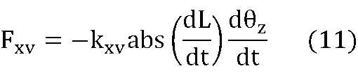
具体例3-2は、具体例3-1で説明した擬似力覚呈示装置1のx軸方向の位置の時間変化dx/dtを、擬似力覚呈示装置1のz軸周りの角速度Θzの時間変化dΘz/dtで近似するものである。すなわち、具体例3-2は、力覚呈示機構15が物理量P1=Lの時間変化dL/dt、および、擬似力覚呈示装置1のz軸周りの角速度Θzの時間変化dΘz/dtに応じた非対称運動を行い、当該非対称運動に基づいた擬似的な力覚(物理量P1=Lの時間変化dL/dtおよび擬似力覚呈示装置1のz軸周りの角速度の時間変化dΘz/dtに応じた擬似的な力覚)を呈示する例である。軸方向の位置の時間変化dx/dtを得るためにはカルマンフィルタ等を用いた複雑な計算が必要となるが、角速度の時間変化dΘz/dtはジャイロセンサ等の簡易なセンサを位置・姿勢計測部12として用いることで容易に計算できる。よって、具体例3-2は具体例3-1に比べ、擬似力覚呈示装置1の構成を簡易にできる。この例の場合、距離計測部11が擬似力覚呈示装置1から外界対象物101までのy軸方向の距離Lを計測し、位置・姿勢計測部12が擬似力覚呈示装置1のz軸周りの角速度の時間変化dΘz/dtを特定するための物理量P2(例えば、擬似力覚呈示装置1のx軸上の位置、速度、または、加速度)を計測し、物理量P1=Lおよび物理量P2が演算部13に入力される。演算部13は、以下のような擬似的な力覚Fxvを認知させるための制御信号CSを生成して出力する。

ただし、図5Aおよび図5Bに例示するように、z軸周りの角速度Θzはz軸方向(図5Aおよび図5Bの奥から手前に向かう方向)で見たときの時計回り(図5Aおよび図5Bにおける反時計回り)の方向を正方向とする。
具体例3-2は、具体例3-1で説明した擬似力覚呈示装置1のx軸方向の位置の時間変化dx/dtを、擬似力覚呈示装置1のz軸周りの角速度Θzの時間変化dΘz/dtで近似するものである。すなわち、具体例3-2は、力覚呈示機構15が物理量P1=Lの時間変化dL/dt、および、擬似力覚呈示装置1のz軸周りの角速度Θzの時間変化dΘz/dtに応じた非対称運動を行い、当該非対称運動に基づいた擬似的な力覚(物理量P1=Lの時間変化dL/dtおよび擬似力覚呈示装置1のz軸周りの角速度の時間変化dΘz/dtに応じた擬似的な力覚)を呈示する例である。軸方向の位置の時間変化dx/dtを得るためにはカルマンフィルタ等を用いた複雑な計算が必要となるが、角速度の時間変化dΘz/dtはジャイロセンサ等の簡易なセンサを位置・姿勢計測部12として用いることで容易に計算できる。よって、具体例3-2は具体例3-1に比べ、擬似力覚呈示装置1の構成を簡易にできる。この例の場合、距離計測部11が擬似力覚呈示装置1から外界対象物101までのy軸方向の距離Lを計測し、位置・姿勢計測部12が擬似力覚呈示装置1のz軸周りの角速度の時間変化dΘz/dtを特定するための物理量P2(例えば、擬似力覚呈示装置1のx軸上の位置、速度、または、加速度)を計測し、物理量P1=Lおよび物理量P2が演算部13に入力される。演算部13は、以下のような擬似的な力覚Fxvを認知させるための制御信号CSを生成して出力する。
ただし、図5Aおよび図5Bに例示するように、z軸周りの角速度Θzはz軸方向(図5Aおよび図5Bの奥から手前に向かう方向)で見たときの時計回り(図5Aおよび図5Bにおける反時計回り)の方向を正方向とする。
≪具体例3-3≫
具体例3-3は、力覚呈示機構15が物理量P1=Lの時間変化dL/dtの絶対値、および、擬似力覚呈示装置1のx軸方向の位置の時間変化dx/dtに応じた非対称運動を行い、当該非対称運動に基づいた擬似的な力覚(物理量P1=Lの時間変化dL/dtの絶対値および擬似力覚呈示装置1のx軸方向の位置の時間変化dx/dtに応じた擬似的な力覚)を呈示する例である。この例の場合、距離計測部11が擬似力覚呈示装置1から外界対象物101までのy軸方向の距離Lを計測し、位置・姿勢計測部12が擬似力覚呈示装置1のx軸上の移動速度を特定するための物理量P2(例えば、擬似力覚呈示装置1のx軸上の位置、速度、または、加速度)を計測し、物理量P1=Lおよび物理量P2が演算部13に入力される。演算部13は、以下のような擬似的な力覚Fxvを認知させるための制御信号CSを生成して出力する。

このような制御信号CSに対応する駆動信号DSが力覚呈示機構15に供給されると、利用者100は次のような擬似的な力覚を認知する。dx/dtが正であるか負である場合、利用者100はx軸の値が大きくなる方向(右方向)に擬似的な力覚を知覚する。dx/dtが負である場合、利用者100はx軸の値が小さくなる方向(左方向)に擬似的な力覚を知覚する。なお、いずれの方向の擬似的な力覚もdL/dtの絶対値が大きいほど大きく、dx/dtの絶対値が大きいほど大きい。これにより、擬似力覚呈示装置1をx軸方向に速く移動させるほど擬似的な力覚の大きさも大きくなり、Lの時間変化が大きいほど擬似的な力覚の大きさも大きくなる。
具体例3-3は、力覚呈示機構15が物理量P1=Lの時間変化dL/dtの絶対値、および、擬似力覚呈示装置1のx軸方向の位置の時間変化dx/dtに応じた非対称運動を行い、当該非対称運動に基づいた擬似的な力覚(物理量P1=Lの時間変化dL/dtの絶対値および擬似力覚呈示装置1のx軸方向の位置の時間変化dx/dtに応じた擬似的な力覚)を呈示する例である。この例の場合、距離計測部11が擬似力覚呈示装置1から外界対象物101までのy軸方向の距離Lを計測し、位置・姿勢計測部12が擬似力覚呈示装置1のx軸上の移動速度を特定するための物理量P2(例えば、擬似力覚呈示装置1のx軸上の位置、速度、または、加速度)を計測し、物理量P1=Lおよび物理量P2が演算部13に入力される。演算部13は、以下のような擬似的な力覚Fxvを認知させるための制御信号CSを生成して出力する。
このような制御信号CSに対応する駆動信号DSが力覚呈示機構15に供給されると、利用者100は次のような擬似的な力覚を認知する。dx/dtが正であるか負である場合、利用者100はx軸の値が大きくなる方向(右方向)に擬似的な力覚を知覚する。dx/dtが負である場合、利用者100はx軸の値が小さくなる方向(左方向)に擬似的な力覚を知覚する。なお、いずれの方向の擬似的な力覚もdL/dtの絶対値が大きいほど大きく、dx/dtの絶対値が大きいほど大きい。これにより、擬似力覚呈示装置1をx軸方向に速く移動させるほど擬似的な力覚の大きさも大きくなり、Lの時間変化が大きいほど擬似的な力覚の大きさも大きくなる。
≪具体例3-4≫
具体例3-4は、具体例3-3で説明した擬似力覚呈示装置1のx軸方向の位置の時間変化dx/dtを、擬似力覚呈示装置1のz軸周りの角速度Θzの時間変化dΘz/dtで近似するものである。この例の場合、距離計測部11が擬似力覚呈示装置1から外界対象物101までのy軸方向の距離Lを計測し、位置・姿勢計測部12が擬似力覚呈示装置1のz軸周りの角速度の時間変化dΘz/dtを特定するための物理量P2を計測し、物理量P1=Lおよび物理量P2が演算部13に入力される。演算部13は、以下のような擬似的な力覚Fxvを認知させるための制御信号CSを生成して出力する。
具体例3-4は、具体例3-3で説明した擬似力覚呈示装置1のx軸方向の位置の時間変化dx/dtを、擬似力覚呈示装置1のz軸周りの角速度Θzの時間変化dΘz/dtで近似するものである。この例の場合、距離計測部11が擬似力覚呈示装置1から外界対象物101までのy軸方向の距離Lを計測し、位置・姿勢計測部12が擬似力覚呈示装置1のz軸周りの角速度の時間変化dΘz/dtを特定するための物理量P2を計測し、物理量P1=Lおよび物理量P2が演算部13に入力される。演算部13は、以下のような擬似的な力覚Fxvを認知させるための制御信号CSを生成して出力する。
≪具体例4-1≫
上述した擬似的な力覚Fyp,Fyvの成分を合成したものをy軸方向に呈示し、擬似的な力覚Fxvをx軸方向に呈示してもよい。例えば、演算部13が、以下のような擬似的な力覚FyおよびFxを認知させるための制御信号CSを生成して出力してもよい。
Fy=Fyp+Fyv (12)
Fx=Fxv (13)
ただし、擬似的な力覚Fyの向きはy軸方向である。擬似力覚呈示装置1から外界対象物101に向かう方向の擬似的な力覚Fyを正値で表し、逆に外界対象物101から擬似力覚呈示装置1に向かう方向の擬似的な力覚Fyを負値で表す。擬似的な力覚Fxの向きはx軸方向である。図5Aおよび図5Bにおける右方向の擬似的な力覚Fxを正値で表し、左方向の擬似的な力覚Fxを負値で表す。
上述した擬似的な力覚Fyp,Fyvの成分を合成したものをy軸方向に呈示し、擬似的な力覚Fxvをx軸方向に呈示してもよい。例えば、演算部13が、以下のような擬似的な力覚FyおよびFxを認知させるための制御信号CSを生成して出力してもよい。
Fy=Fyp+Fyv (12)
Fx=Fxv (13)
ただし、擬似的な力覚Fyの向きはy軸方向である。擬似力覚呈示装置1から外界対象物101に向かう方向の擬似的な力覚Fyを正値で表し、逆に外界対象物101から擬似力覚呈示装置1に向かう方向の擬似的な力覚Fyを負値で表す。擬似的な力覚Fxの向きはx軸方向である。図5Aおよび図5Bにおける右方向の擬似的な力覚Fxを正値で表し、左方向の擬似的な力覚Fxを負値で表す。
≪具体例4-2≫
具体例4-1においてFy=Fypとしてもよいし、Fy=Fyvとしてもよい。
具体例4-1においてFy=Fypとしてもよいし、Fy=Fyvとしてもよい。
≪具体例5-1≫
飽和特性等を考慮し、演算部13が、具体例4の擬似的な力覚FyおよびFxを非線形変換した擬似的な力覚をF’yおよびF’xを認知させるための制御信号CSを生成して出力してもよい。例えば、演算部13が、以下のようなFyおよびFxのシグモイド関数値である擬似的な力覚F’yおよびF’xを認知させるための制御信号CSを生成して出力してもよい。


ただし、kgy1,kgy2,kgx1,kgx2は正のゲイン定数である。exp(α)はαの指数関数値である。擬似的な力覚Fyの向きはy軸方向である。擬似力覚呈示装置1から外界対象物101に向かう方向の擬似的な力覚F’yを正値で表し、逆に外界対象物101から擬似力覚呈示装置1に向かう方向の擬似的な力覚F’yを負値で表す。擬似的な力覚F’xの向きはx軸方向である。図5Aおよび図5Bにおける右方向の擬似的な力覚F’xを正値で表し、左方向の擬似的な力覚F’xを負値で表す。これにより、呈示される疑似的な力覚を知覚のダイナミックレンジと整合させることができる。
飽和特性等を考慮し、演算部13が、具体例4の擬似的な力覚FyおよびFxを非線形変換した擬似的な力覚をF’yおよびF’xを認知させるための制御信号CSを生成して出力してもよい。例えば、演算部13が、以下のようなFyおよびFxのシグモイド関数値である擬似的な力覚F’yおよびF’xを認知させるための制御信号CSを生成して出力してもよい。
ただし、kgy1,kgy2,kgx1,kgx2は正のゲイン定数である。exp(α)はαの指数関数値である。擬似的な力覚Fyの向きはy軸方向である。擬似力覚呈示装置1から外界対象物101に向かう方向の擬似的な力覚F’yを正値で表し、逆に外界対象物101から擬似力覚呈示装置1に向かう方向の擬似的な力覚F’yを負値で表す。擬似的な力覚F’xの向きはx軸方向である。図5Aおよび図5Bにおける右方向の擬似的な力覚F’xを正値で表し、左方向の擬似的な力覚F’xを負値で表す。これにより、呈示される疑似的な力覚を知覚のダイナミックレンジと整合させることができる。
≪具体例5-2≫
演算部13が、以下のようなFyの区分線形関数値で表される疑似的な力覚F’yを認知させるための制御信号CSを生成して出力してもよい。
F'y=Fy for -Fy max<Fy<Fy max (14)
F'y=Fy max for Fy max≦Fy (15)
F'y=-Fy max for -Fy max≧Fy (16)
ただし、Fy maxは疑似的な力覚Fyの最大値である。
演算部13が、以下のようなFyの区分線形関数値で表される疑似的な力覚F’yを認知させるための制御信号CSを生成して出力してもよい。
F'y=Fy for -Fy max<Fy<Fy max (14)
F'y=Fy max for Fy max≦Fy (15)
F'y=-Fy max for -Fy max≧Fy (16)
ただし、Fy maxは疑似的な力覚Fyの最大値である。
≪具体例5-3≫
具体例5-1,5-2においてFy=Fypとしてもよいし、Fy=Fyvとしてもよい。
具体例5-1,5-2においてFy=Fypとしてもよいし、Fy=Fyvとしてもよい。
以上に例示するように、力覚呈示機構15は、物理量P1=Lに応じた非対称運動を行い、物理量P1=Lに応じた擬似的な力覚を呈示してもよいし(モードA:具体例1-1,1-2)、物理量P1=Lの時間変化に応じた非対称運動を行い、物理量P1=Lの時間変化に応じた擬似的な力覚を呈示してもよい(モードB:具体例2-1,2-2)。また、力覚呈示機構15は、擬似力覚呈示装置1の動きを計測して得られた物理量P2、物理量P2の関数値、擬似力覚呈示装置1の姿勢を計測して得られた物理量P3、および第3物理量P3の関数値、の少なくとも何れか、ならびに、物理量P1=Lの時間変化、に応じた非対称運動を行い、物理量P2、物理量P2の関数値、物理量P3、物理量P3の関数値、の少なくとも何れか、ならびに、物理量P1=Lの時間変化に応じた擬似的な力覚を呈示してもよい(モードC:具体例3-1,3-2,3-3,3-4)。また、力覚呈示機構15がモードA~Cの疑似的な力覚の少なくとも一部を合成したものを呈示してもよいし、力覚呈示機構15がモードA~Cの疑似的な力覚の少なくとも一部を非線形変換して合成したものを呈示してもよい(モードD:具体例4-1,4-2,5-1,5-2,5-3)。
≪位置関係と擬似的な力覚との関係の例示1≫
外界対象物101と擬似力覚呈示装置1との位置関係と擬似力覚呈示装置1が呈示する擬似的な力覚との関係を例示する。図6Aから図9Bは、擬似力覚呈示装置1がy軸方向に式(5)の擬似的な力覚Fy=Fyvを呈示し、x軸方向に式(8)の擬似的な力覚Fx=Fxvを呈示する場合の例である。図6A,図7A,図8A,図9Aにおける1から8の数字はx-y平面における方向を表す。図6B,図7B,図8B,図9Bは、それぞれ、擬似力覚呈示装置1および壁である外界対象物101が図6B,図7B,図8B,図9Bの位置関係にあるときに、上述の1から8の数字で示されたx-y平面における方向に擬似力覚呈示装置1が単位速度で平行移動する場合に、擬似力覚呈示装置1が呈示する擬似的な力覚FyおよびFxの合成をベクトル表示したものである。外界対象物101は静止している。各ベクトルには対応する擬似力覚呈示装置1の移動方向を表す数字を付している。これらの図に示すように、外界対象物101までの距離Lが長くなる方向へ擬似力覚呈示装置1が移動する場合(図6Aの5,6,7の方向、図7Aの6,7,8の方向、図8Aの1,6,7,8の方向、図9Aの1,7,8の方向)、擬似力覚呈示装置1は移動方向のy軸成分の反対向きの成分および移動方向のx軸方向成分(図6Bの5,6,7の方向成分、図7Bの6,7,8の方向成分、図8Bの1,6,7,8の方向成分、図9Bの1,7,8の方向成分)を持つ擬似的な力覚を呈示する。一方、外界対象物101までの距離Lが短くなる方向へ擬似力覚呈示装置1が移動する場合(図6Aの1,2,3の方向、図7Aの2,3,4の方向、図8Aの2,3,4,5の方向、図9Aの3,4,5の方向)、擬似力覚呈示装置1は移動方向のy軸成分の反対向きの成分および移動方向のx軸方向成分の反対向きの成分(図6Bの1,2,3の方向成分、図7Bの2,3,4の方向成分、図8Bの2,3,4,5の方向成分、図9Bの3,4,5の方向成分)を持つ擬似的な力覚を呈示する。図6Aの4,8で示された方向、図7Aの1,5で示された方向、図9Aの2,6で示された方向に擬似力覚呈示装置1が移動する場合には、擬似的な力覚は呈示されない。
外界対象物101と擬似力覚呈示装置1との位置関係と擬似力覚呈示装置1が呈示する擬似的な力覚との関係を例示する。図6Aから図9Bは、擬似力覚呈示装置1がy軸方向に式(5)の擬似的な力覚Fy=Fyvを呈示し、x軸方向に式(8)の擬似的な力覚Fx=Fxvを呈示する場合の例である。図6A,図7A,図8A,図9Aにおける1から8の数字はx-y平面における方向を表す。図6B,図7B,図8B,図9Bは、それぞれ、擬似力覚呈示装置1および壁である外界対象物101が図6B,図7B,図8B,図9Bの位置関係にあるときに、上述の1から8の数字で示されたx-y平面における方向に擬似力覚呈示装置1が単位速度で平行移動する場合に、擬似力覚呈示装置1が呈示する擬似的な力覚FyおよびFxの合成をベクトル表示したものである。外界対象物101は静止している。各ベクトルには対応する擬似力覚呈示装置1の移動方向を表す数字を付している。これらの図に示すように、外界対象物101までの距離Lが長くなる方向へ擬似力覚呈示装置1が移動する場合(図6Aの5,6,7の方向、図7Aの6,7,8の方向、図8Aの1,6,7,8の方向、図9Aの1,7,8の方向)、擬似力覚呈示装置1は移動方向のy軸成分の反対向きの成分および移動方向のx軸方向成分(図6Bの5,6,7の方向成分、図7Bの6,7,8の方向成分、図8Bの1,6,7,8の方向成分、図9Bの1,7,8の方向成分)を持つ擬似的な力覚を呈示する。一方、外界対象物101までの距離Lが短くなる方向へ擬似力覚呈示装置1が移動する場合(図6Aの1,2,3の方向、図7Aの2,3,4の方向、図8Aの2,3,4,5の方向、図9Aの3,4,5の方向)、擬似力覚呈示装置1は移動方向のy軸成分の反対向きの成分および移動方向のx軸方向成分の反対向きの成分(図6Bの1,2,3の方向成分、図7Bの2,3,4の方向成分、図8Bの2,3,4,5の方向成分、図9Bの3,4,5の方向成分)を持つ擬似的な力覚を呈示する。図6Aの4,8で示された方向、図7Aの1,5で示された方向、図9Aの2,6で示された方向に擬似力覚呈示装置1が移動する場合には、擬似的な力覚は呈示されない。
≪位置関係と擬似的な力覚との関係の例示2≫
図10Aから図13Bは、擬似力覚呈示装置1がy軸方向に式(5)の擬似的な力覚Fy=Fyvを呈示し、x軸方向に式(10)の擬似的な力覚Fx=Fxvを呈示する場合の例である。図10A,図11A,図12A,図13Aにおける1から8の数字はx-y平面における方向を表す。図10B,図11B,図12B,図13Bは、それぞれ、擬似力覚呈示装置1および壁である外界対象物101が図10B,図11B,図12B,図13Bの位置関係にあるときに、上述の1から8の数字で示されたx-y平面における方向に擬似力覚呈示装置1が単位速度で平行移動する場合に、擬似力覚呈示装置1が呈示する擬似的な力覚FyおよびFxの合成をベクトル表示したものである。外界対象物101は静止している。各ベクトルには対応する擬似力覚呈示装置1の移動方向を表す数字を付している。これらの例では、擬似力覚呈示装置1の移動方向にかかわらず、擬似力覚呈示装置1は移動方向のy軸成分の反対向きの成分および移動方向のx軸方向成分を持つ擬似的な力覚を呈示する。図10Aの4,8で示された方向、図11Aの1,5で示された方向、図13Aの2,6で示された方向に擬似力覚呈示装置1が移動する場合には、擬似的な力覚は呈示されない。
図10Aから図13Bは、擬似力覚呈示装置1がy軸方向に式(5)の擬似的な力覚Fy=Fyvを呈示し、x軸方向に式(10)の擬似的な力覚Fx=Fxvを呈示する場合の例である。図10A,図11A,図12A,図13Aにおける1から8の数字はx-y平面における方向を表す。図10B,図11B,図12B,図13Bは、それぞれ、擬似力覚呈示装置1および壁である外界対象物101が図10B,図11B,図12B,図13Bの位置関係にあるときに、上述の1から8の数字で示されたx-y平面における方向に擬似力覚呈示装置1が単位速度で平行移動する場合に、擬似力覚呈示装置1が呈示する擬似的な力覚FyおよびFxの合成をベクトル表示したものである。外界対象物101は静止している。各ベクトルには対応する擬似力覚呈示装置1の移動方向を表す数字を付している。これらの例では、擬似力覚呈示装置1の移動方向にかかわらず、擬似力覚呈示装置1は移動方向のy軸成分の反対向きの成分および移動方向のx軸方向成分を持つ擬似的な力覚を呈示する。図10Aの4,8で示された方向、図11Aの1,5で示された方向、図13Aの2,6で示された方向に擬似力覚呈示装置1が移動する場合には、擬似的な力覚は呈示されない。
≪外界対象物101の形状と擬似的な力覚との関係の例示1≫
外界対象物101の形状と擬似力覚呈示装置1が呈示する擬似的な力覚との関係を例示する。図14Aから図16Dは、擬似力覚呈示装置1がy軸方向に式(5)の擬似的な力覚Fy=Fyvを呈示し、x軸方向に式(8)の擬似的な力覚Fx=Fxvを呈示する場合の例である。図14Bから図14Dは、図14Aのように断面形状が矩形型のくぼみ(y軸方向のくぼみ)を持つ外界対象物101に対し、擬似力覚呈示装置1をx軸方向に秒速0.25m/sで移動させた場合における、時間[s]と、擬似力覚呈示装置1から外界対象物101までの距離L[m]、擬似的な力覚Fx、および擬似的な力覚Fyとの関係をそれぞれ例示している。断面形状が矩形型のくぼみを持つ外界対象物101の場合、擬似力覚呈示装置1がくぼみに差し掛かったところで、擬似力覚呈示装置1が外界対象物101に引き寄せられるような擬似的な力覚Fx,Fyが呈示される(FxおよびFyが共に正)。これにより、利用者100は、擬似力覚呈示装置1が外界対象物101のくぼみにy軸方向に落ち込み、さらにx軸方向に加速するような感覚が得られる。これは手で外界対象物101をなぞる際の感覚に似ている。擬似力覚呈示装置1がくぼみに対向している時点では擬似的な力覚Fx,Fyは0である。その後、擬似力覚呈示装置1がくぼみの終わりに差し掛かったところで、擬似力覚呈示装置1が外界対象物101から押し出され、かつ、擬似力覚呈示装置1の進行方向の逆向きに押されるような擬似的な力覚が呈示される(FxおよびFyが共に負)。これにより、利用者100は、擬似力覚呈示装置1が外界対象物101のくぼみの終端でx軸方向に減速し、y軸方向に押し戻されるような感覚が得られる。これも手で外界対象物101をなぞる際の感覚に似ている。図15Bから図15Dは、図15Aのように断面形状が楔形のくぼみ(y軸方向のくぼみ)を持つ外界対象物101に対し、擬似力覚呈示装置1をx軸方向に秒速0.25m/sで移動させた場合における、時間[s]と、擬似力覚呈示装置1から外界対象物101までの距離L[m]、擬似的な力覚Fx、および擬似的な力覚Fyとの関係をそれぞれ例示している。断面形状が楔形のくぼみを持つ外界対象物101の場合、擬似力覚呈示装置1がくぼみに差し掛かってからくぼみの最も深い部分に対向する位置に達するまで、正の擬似的な力覚Fx,Fyが継続的に呈示される。その後、擬似力覚呈示装置1がくぼみの終わりに達するまで、負の擬似的な力覚Fx,Fyが継続的に呈示される。図16Bから図16Dは、図16Aのように断面形状が半円型のくぼみ(y軸方向のくぼみ)を持つ外界対象物101に対し、擬似力覚呈示装置1をx軸方向に秒速0.25m/sで移動させた場合における、時間[s]と、擬似力覚呈示装置1から外界対象物101までの距離L[m]、擬似的な力覚Fx、および擬似的な力覚Fyとの関係をそれぞれ例示している。断面形状が半円型のくぼみを持つ外界対象物101の場合、擬似力覚呈示装置1がくぼみに差し掛かってからくぼみの最も深い部分に対向する位置に達するまで、正の擬似的な力覚Fx,Fyが継続的に呈示される。その後、擬似力覚呈示装置1がくぼみの終わりに達するまで、負の擬似的な力覚Fx,Fyが継続的に呈示される。ただし、断面形状が半円型のくぼみの場合には距離Lが連続的に変化するため、擬似的な力覚Fx,Fyの大きさは連続的に変化する。以上のように、擬似的な力覚Fx,Fyにより、利用者100に外界対象物101の形状をクリアに認知させることができる。
外界対象物101の形状と擬似力覚呈示装置1が呈示する擬似的な力覚との関係を例示する。図14Aから図16Dは、擬似力覚呈示装置1がy軸方向に式(5)の擬似的な力覚Fy=Fyvを呈示し、x軸方向に式(8)の擬似的な力覚Fx=Fxvを呈示する場合の例である。図14Bから図14Dは、図14Aのように断面形状が矩形型のくぼみ(y軸方向のくぼみ)を持つ外界対象物101に対し、擬似力覚呈示装置1をx軸方向に秒速0.25m/sで移動させた場合における、時間[s]と、擬似力覚呈示装置1から外界対象物101までの距離L[m]、擬似的な力覚Fx、および擬似的な力覚Fyとの関係をそれぞれ例示している。断面形状が矩形型のくぼみを持つ外界対象物101の場合、擬似力覚呈示装置1がくぼみに差し掛かったところで、擬似力覚呈示装置1が外界対象物101に引き寄せられるような擬似的な力覚Fx,Fyが呈示される(FxおよびFyが共に正)。これにより、利用者100は、擬似力覚呈示装置1が外界対象物101のくぼみにy軸方向に落ち込み、さらにx軸方向に加速するような感覚が得られる。これは手で外界対象物101をなぞる際の感覚に似ている。擬似力覚呈示装置1がくぼみに対向している時点では擬似的な力覚Fx,Fyは0である。その後、擬似力覚呈示装置1がくぼみの終わりに差し掛かったところで、擬似力覚呈示装置1が外界対象物101から押し出され、かつ、擬似力覚呈示装置1の進行方向の逆向きに押されるような擬似的な力覚が呈示される(FxおよびFyが共に負)。これにより、利用者100は、擬似力覚呈示装置1が外界対象物101のくぼみの終端でx軸方向に減速し、y軸方向に押し戻されるような感覚が得られる。これも手で外界対象物101をなぞる際の感覚に似ている。図15Bから図15Dは、図15Aのように断面形状が楔形のくぼみ(y軸方向のくぼみ)を持つ外界対象物101に対し、擬似力覚呈示装置1をx軸方向に秒速0.25m/sで移動させた場合における、時間[s]と、擬似力覚呈示装置1から外界対象物101までの距離L[m]、擬似的な力覚Fx、および擬似的な力覚Fyとの関係をそれぞれ例示している。断面形状が楔形のくぼみを持つ外界対象物101の場合、擬似力覚呈示装置1がくぼみに差し掛かってからくぼみの最も深い部分に対向する位置に達するまで、正の擬似的な力覚Fx,Fyが継続的に呈示される。その後、擬似力覚呈示装置1がくぼみの終わりに達するまで、負の擬似的な力覚Fx,Fyが継続的に呈示される。図16Bから図16Dは、図16Aのように断面形状が半円型のくぼみ(y軸方向のくぼみ)を持つ外界対象物101に対し、擬似力覚呈示装置1をx軸方向に秒速0.25m/sで移動させた場合における、時間[s]と、擬似力覚呈示装置1から外界対象物101までの距離L[m]、擬似的な力覚Fx、および擬似的な力覚Fyとの関係をそれぞれ例示している。断面形状が半円型のくぼみを持つ外界対象物101の場合、擬似力覚呈示装置1がくぼみに差し掛かってからくぼみの最も深い部分に対向する位置に達するまで、正の擬似的な力覚Fx,Fyが継続的に呈示される。その後、擬似力覚呈示装置1がくぼみの終わりに達するまで、負の擬似的な力覚Fx,Fyが継続的に呈示される。ただし、断面形状が半円型のくぼみの場合には距離Lが連続的に変化するため、擬似的な力覚Fx,Fyの大きさは連続的に変化する。以上のように、擬似的な力覚Fx,Fyにより、利用者100に外界対象物101の形状をクリアに認知させることができる。
≪外界対象物101の形状と擬似的な力覚との関係の例示2≫
他の例を示す。図17Aから図19Dは、擬似力覚呈示装置1がy軸方向に式(1)(2)および式(5)の擬似的な力覚を合成した擬似的な力覚Fy=Fyp+Fyvを呈示し、x軸方向に式(8)の擬似的な力覚Fx=Fxvを呈示する場合の例である。図17Bから図17Dは、図17Aのように断面形状が矩形型のくぼみ(y軸方向のくぼみ)を持つ外界対象物101に対し、擬似力覚呈示装置1をx軸方向に秒速0.25m/sで移動させた場合における、時間[s]と、擬似力覚呈示装置1から外界対象物101までの距離L[m]、擬似的な力覚Fx、および擬似的な力覚Fyとの関係をそれぞれ例示している。断面形状が矩形型のくぼみを持つ外界対象物101の場合、擬似力覚呈示装置1がくぼみに差し掛かったところで、擬似力覚呈示装置1が外界対象物101に引き寄せられるような擬似的な力覚Fx,Fyが呈示される(FxおよびFyが共に正)。擬似力覚呈示装置1がくぼみに対向している時点では擬似的な力覚Fx,Fyは0である。その後、擬似力覚呈示装置1がくぼみの終わりに差し掛かったところで、擬似力覚呈示装置1が外界対象物101から押し出され、かつ、擬似力覚呈示装置1の進行方向の逆向きに押されるような擬似的な力覚が呈示される(FxおよびFyが共に負)。図18Bから図18Dは、図18Aのように断面形状が楔形のくぼみ(y軸方向のくぼみ)を持つ外界対象物101に対し、擬似力覚呈示装置1をx軸方向に秒速0.25m/sで移動させた場合における、時間[s]と、擬似力覚呈示装置1から外界対象物101までの距離L[m]、擬似的な力覚Fx、および擬似的な力覚Fyとの関係をそれぞれ例示している。断面形状が楔形のくぼみを持つ外界対象物101の場合、擬似力覚呈示装置1がくぼみに差し掛かってからくぼみの最も深い部分に対向する位置に達するまで、正の擬似的な力覚Fx,Fyが継続的に呈示される。その後、擬似力覚呈示装置1がくぼみの終わりに達するまで、負の擬似的な力覚Fx,Fyが継続的に呈示される。ただし、距離Lに依存するFypの成分もFyに含まれるため、y軸方向の擬似的な力覚Fyは時間変化する。図19Bから図19Dは、図19Aのように断面形状が半円型のくぼみ(y軸方向のくぼみ)を持つ外界対象物101に対し、擬似力覚呈示装置1をx軸方向に秒速0.25m/sで移動させた場合における、時間[s]と、擬似力覚呈示装置1から外界対象物101までの距離L[m]、擬似的な力覚Fx、および擬似的な力覚Fyとの関係をそれぞれ例示している。断面形状が半円型のくぼみを持つ外界対象物101の場合、擬似力覚呈示装置1がくぼみに差し掛かってからくぼみの最も深い部分に対向する位置に達するまで、正の擬似的な力覚Fx,Fyが継続的に呈示される。その後、擬似力覚呈示装置1がくぼみの終わりに達するまで、負の擬似的な力覚Fx,Fyが継続的に呈示される。ただし、半円型のくぼみの場合には距離Lが連続的に変化するため、擬似的な力覚Fx,Fyの大きさは連続的に変化する。さらに、距離Lに依存するFypの成分もFyに含まれるため、y軸方向の擬似的な力覚Fyの時間変化はさらに顕著になる。以上の例の場合、Fyが距離Lに依存するFypの成分を含むため、利用者100に外界対象物101の形状をより明確に認知させることができる。
他の例を示す。図17Aから図19Dは、擬似力覚呈示装置1がy軸方向に式(1)(2)および式(5)の擬似的な力覚を合成した擬似的な力覚Fy=Fyp+Fyvを呈示し、x軸方向に式(8)の擬似的な力覚Fx=Fxvを呈示する場合の例である。図17Bから図17Dは、図17Aのように断面形状が矩形型のくぼみ(y軸方向のくぼみ)を持つ外界対象物101に対し、擬似力覚呈示装置1をx軸方向に秒速0.25m/sで移動させた場合における、時間[s]と、擬似力覚呈示装置1から外界対象物101までの距離L[m]、擬似的な力覚Fx、および擬似的な力覚Fyとの関係をそれぞれ例示している。断面形状が矩形型のくぼみを持つ外界対象物101の場合、擬似力覚呈示装置1がくぼみに差し掛かったところで、擬似力覚呈示装置1が外界対象物101に引き寄せられるような擬似的な力覚Fx,Fyが呈示される(FxおよびFyが共に正)。擬似力覚呈示装置1がくぼみに対向している時点では擬似的な力覚Fx,Fyは0である。その後、擬似力覚呈示装置1がくぼみの終わりに差し掛かったところで、擬似力覚呈示装置1が外界対象物101から押し出され、かつ、擬似力覚呈示装置1の進行方向の逆向きに押されるような擬似的な力覚が呈示される(FxおよびFyが共に負)。図18Bから図18Dは、図18Aのように断面形状が楔形のくぼみ(y軸方向のくぼみ)を持つ外界対象物101に対し、擬似力覚呈示装置1をx軸方向に秒速0.25m/sで移動させた場合における、時間[s]と、擬似力覚呈示装置1から外界対象物101までの距離L[m]、擬似的な力覚Fx、および擬似的な力覚Fyとの関係をそれぞれ例示している。断面形状が楔形のくぼみを持つ外界対象物101の場合、擬似力覚呈示装置1がくぼみに差し掛かってからくぼみの最も深い部分に対向する位置に達するまで、正の擬似的な力覚Fx,Fyが継続的に呈示される。その後、擬似力覚呈示装置1がくぼみの終わりに達するまで、負の擬似的な力覚Fx,Fyが継続的に呈示される。ただし、距離Lに依存するFypの成分もFyに含まれるため、y軸方向の擬似的な力覚Fyは時間変化する。図19Bから図19Dは、図19Aのように断面形状が半円型のくぼみ(y軸方向のくぼみ)を持つ外界対象物101に対し、擬似力覚呈示装置1をx軸方向に秒速0.25m/sで移動させた場合における、時間[s]と、擬似力覚呈示装置1から外界対象物101までの距離L[m]、擬似的な力覚Fx、および擬似的な力覚Fyとの関係をそれぞれ例示している。断面形状が半円型のくぼみを持つ外界対象物101の場合、擬似力覚呈示装置1がくぼみに差し掛かってからくぼみの最も深い部分に対向する位置に達するまで、正の擬似的な力覚Fx,Fyが継続的に呈示される。その後、擬似力覚呈示装置1がくぼみの終わりに達するまで、負の擬似的な力覚Fx,Fyが継続的に呈示される。ただし、半円型のくぼみの場合には距離Lが連続的に変化するため、擬似的な力覚Fx,Fyの大きさは連続的に変化する。さらに、距離Lに依存するFypの成分もFyに含まれるため、y軸方向の擬似的な力覚Fyの時間変化はさらに顕著になる。以上の例の場合、Fyが距離Lに依存するFypの成分を含むため、利用者100に外界対象物101の形状をより明確に認知させることができる。
[第1実施形態の変形例1]
前述した複数のモードA~Dから特定のモードが選択可能であってもよいし、各モードで呈示される疑似的な力覚が選択可能(例えば、前述した具体例の式に示される擬似的な力覚からの選択)であってもよい。このように選択される疑似的な力覚の種別を「力覚種別」と呼ぶことにする。この場合、擬似力覚呈示装置1は、演算部13に代え、力覚種別を選択する機能を持つ演算部13’を有する。演算部13’には複数の力覚種別から選択された特定の力覚種別を示す選択情報μが入力される。演算部13’は当該選択情報μが示す力覚種別を設定し、力覚呈示機構15が当該設定された力覚種別での擬似的な力覚を呈示するための制御信号CSを第1実施形態で説明したように得て出力する。すなわち、複数の力覚種別のそれぞれは、物理量P1、物理量P1の関数値、物理量P2、物理量P2の関数値、物理量P3、および物理量P3の関数値、の少なくとも何れかを含む物理情報に対応し、力覚呈示機構15は、選択された特定の力覚種別に対応する物理情報に応じた非対称運動を行い、当該特定の力覚種別に対応する物理情報に応じた擬似的な力覚を呈示する。これにより、様々な状況に応じて適切な擬似的な力覚を呈示できる。例えば、外界対象物101の形状に応じて疑似的な力覚を切り替え、外界対象物101の形状に関する情報をより明確に利用者100に知覚させることができる。
前述した複数のモードA~Dから特定のモードが選択可能であってもよいし、各モードで呈示される疑似的な力覚が選択可能(例えば、前述した具体例の式に示される擬似的な力覚からの選択)であってもよい。このように選択される疑似的な力覚の種別を「力覚種別」と呼ぶことにする。この場合、擬似力覚呈示装置1は、演算部13に代え、力覚種別を選択する機能を持つ演算部13’を有する。演算部13’には複数の力覚種別から選択された特定の力覚種別を示す選択情報μが入力される。演算部13’は当該選択情報μが示す力覚種別を設定し、力覚呈示機構15が当該設定された力覚種別での擬似的な力覚を呈示するための制御信号CSを第1実施形態で説明したように得て出力する。すなわち、複数の力覚種別のそれぞれは、物理量P1、物理量P1の関数値、物理量P2、物理量P2の関数値、物理量P3、および物理量P3の関数値、の少なくとも何れかを含む物理情報に対応し、力覚呈示機構15は、選択された特定の力覚種別に対応する物理情報に応じた非対称運動を行い、当該特定の力覚種別に対応する物理情報に応じた擬似的な力覚を呈示する。これにより、様々な状況に応じて適切な擬似的な力覚を呈示できる。例えば、外界対象物101の形状に応じて疑似的な力覚を切り替え、外界対象物101の形状に関する情報をより明確に利用者100に知覚させることができる。
あるいは、演算部13’に選択情報μが入力されるのではなく、擬似力覚呈示装置1の内部で取得可能な情報(例えば、時間、方向、速度、加速度など)に応じ、演算部13’の内部で力覚種別の選択および設定が行われてもよい。
[第2実施形態]
第2実施形態は、第1実施形態の変形例であり、演算部13の機能が擬似力覚呈示装置の外部に設けられる。以下、既に説明した事項については同じ参照番号を用いて説明を簡略化する。
第2実施形態は、第1実施形態の変形例であり、演算部13の機能が擬似力覚呈示装置の外部に設けられる。以下、既に説明した事項については同じ参照番号を用いて説明を簡略化する。
<構成>
図20に例示するように、本実施形態の擬似力覚呈示装置2は、距離計測部11、位置・姿勢計測部12、制御部14、力覚呈示機構15、ケース16、出力部26、および入力部27を有する。また、擬似力覚呈示装置2の外部には、擬似力覚呈示装置2と無線通信または有線通信が可能な演算装置23が設けられている。演算装置23は、例えば、汎用または専用のコンピュータが所定のプログラムを実行することで構成される。このコンピュータは1個のプロセッサやメモリを備えていてもよいし、複数個のプロセッサやメモリを備えていてもよい。このプログラムはコンピュータにインストールされてもよいし、予めROM等に記録されていてもよい。また、CPUのようにプログラムが読み込まれることで機能構成を実現する電子回路(circuitry)ではなく、プログラムを用いることなく処理機能を実現する電子回路を用いて一部またはすべての処理部が構成されてもよい。1個の装置を構成する電子回路が複数のCPUを含んでいてもよい。
図20に例示するように、本実施形態の擬似力覚呈示装置2は、距離計測部11、位置・姿勢計測部12、制御部14、力覚呈示機構15、ケース16、出力部26、および入力部27を有する。また、擬似力覚呈示装置2の外部には、擬似力覚呈示装置2と無線通信または有線通信が可能な演算装置23が設けられている。演算装置23は、例えば、汎用または専用のコンピュータが所定のプログラムを実行することで構成される。このコンピュータは1個のプロセッサやメモリを備えていてもよいし、複数個のプロセッサやメモリを備えていてもよい。このプログラムはコンピュータにインストールされてもよいし、予めROM等に記録されていてもよい。また、CPUのようにプログラムが読み込まれることで機能構成を実現する電子回路(circuitry)ではなく、プログラムを用いることなく処理機能を実現する電子回路を用いて一部またはすべての処理部が構成されてもよい。1個の装置を構成する電子回路が複数のCPUを含んでいてもよい。
<動作>
次に、第2実施形態の擬似力覚呈示装置2の動作を説明する。第1実施形態との相違点は以下の通りである。第1実施形態では、距離計測部11で得られた物理量P1、ならびに位置・姿勢計測部12で得られた物理量P2および物理量P3の少なくとも一方が演算部13に入力された。これに代え、第2実施形態では、これらの物理量P1ならびに物理量P2および物理量P3の少なくとも一方を表す情報(計測部で得られた計測値を表す情報)が出力部26から出力され、演算装置23に送られる。演算装置23は、物理量P1ならびに物理量P2および物理量P3の少なくとも一方を表す情報を用い、第1実施形態の演算部13の処理を行って制御信号CS(計測値に応じた入力情報)を得て出力する。制御信号CSは、擬似力覚呈示装置2の入力部27に入力され、制御部14に送られる。制御部14は、この制御信号CSに対応する駆動信号DSを生成し、非対称運動部152-iのコイル1524-iに供給する。これにより、力覚呈示機構15は、制御信号CSに応じた非対称運動を行い、当該非対称運動に基づいた擬似的な力覚を呈示する。これにより、擬似力覚呈示装置2を小型化できる。
次に、第2実施形態の擬似力覚呈示装置2の動作を説明する。第1実施形態との相違点は以下の通りである。第1実施形態では、距離計測部11で得られた物理量P1、ならびに位置・姿勢計測部12で得られた物理量P2および物理量P3の少なくとも一方が演算部13に入力された。これに代え、第2実施形態では、これらの物理量P1ならびに物理量P2および物理量P3の少なくとも一方を表す情報(計測部で得られた計測値を表す情報)が出力部26から出力され、演算装置23に送られる。演算装置23は、物理量P1ならびに物理量P2および物理量P3の少なくとも一方を表す情報を用い、第1実施形態の演算部13の処理を行って制御信号CS(計測値に応じた入力情報)を得て出力する。制御信号CSは、擬似力覚呈示装置2の入力部27に入力され、制御部14に送られる。制御部14は、この制御信号CSに対応する駆動信号DSを生成し、非対称運動部152-iのコイル1524-iに供給する。これにより、力覚呈示機構15は、制御信号CSに応じた非対称運動を行い、当該非対称運動に基づいた擬似的な力覚を呈示する。これにより、擬似力覚呈示装置2を小型化できる。
[第2実施形態の変形例1]
その他、演算部13の機能だけではなく制御部14の機能も、擬似力覚呈示装置2の外部の演算装置23に設けられてもよい。この場合には、物理量P1ならびに物理量P2および物理量P3の少なくとも一方を表す情報(計測部で得られた計測値を表す情報)が出力部26から出力され、演算装置23に送られる。演算装置23は、物理量P1ならびに物理量P2および物理量P3の少なくとも一方を表す情報を用い、第1実施形態の演算部13および制御部14の処理を行って制御信号CSおよび駆動信号DS(計測値に応じた入力情報)を得て出力する。駆動信号DSは、擬似力覚呈示装置2の入力部27に入力され、非対称運動部152-iのコイル1524-iに供給される。これにより、力覚呈示機構15は、制御信号CSに応じた非対称運動を行い、当該非対称運動に基づいた擬似的な力覚を呈示する。これにより、擬似力覚呈示装置2をより小型化できる。
その他、演算部13の機能だけではなく制御部14の機能も、擬似力覚呈示装置2の外部の演算装置23に設けられてもよい。この場合には、物理量P1ならびに物理量P2および物理量P3の少なくとも一方を表す情報(計測部で得られた計測値を表す情報)が出力部26から出力され、演算装置23に送られる。演算装置23は、物理量P1ならびに物理量P2および物理量P3の少なくとも一方を表す情報を用い、第1実施形態の演算部13および制御部14の処理を行って制御信号CSおよび駆動信号DS(計測値に応じた入力情報)を得て出力する。駆動信号DSは、擬似力覚呈示装置2の入力部27に入力され、非対称運動部152-iのコイル1524-iに供給される。これにより、力覚呈示機構15は、制御信号CSに応じた非対称運動を行い、当該非対称運動に基づいた擬似的な力覚を呈示する。これにより、擬似力覚呈示装置2をより小型化できる。
[第2実施形態の変形例2]
第2実施形態または第2実施形態の変形例1において、演算装置23が演算部13の機能に代えて、第1実施形態の変形例1で説明した演算部13’の機能を備えてもよい。
第2実施形態または第2実施形態の変形例1において、演算装置23が演算部13の機能に代えて、第1実施形態の変形例1で説明した演算部13’の機能を備えてもよい。
[その他の変形例等]
なお、本発明は上述の実施形態に限定されるものではない。例えば、非対称運動部152-iとして、特許第4551448号公報(参考文献3)、国際公開第WO2007/086426号(参考文献4)、特開2015-226388公報(参考文献5)等のその他の非対称運動に基づいて擬似的な力覚を呈示する装置が用いられてもよい。また、力覚呈示機構15が3個以上の非対称運動部152-iを備え、それらの駆動を制御することで並進方向の疑似的な力覚だけではなく、回転方向の疑似的な力覚も呈示できてもよい(例えば、参考文献1等参照)。また参考文献5に記載された構成の非対称運動部152-1を用い、1個の非対称運動部152-1のみで並進方向および回転方向が呈示できてもよい。距離計測部11および位置・姿勢計測部12での計測結果に応じ、非対称運動部152-iが非対称運動を行い、当該計測結果に応じた2自由度以上の擬似的な力覚が呈示できるのであれば、非対称運動部152-iの構成および個数に制限はない。
なお、本発明は上述の実施形態に限定されるものではない。例えば、非対称運動部152-iとして、特許第4551448号公報(参考文献3)、国際公開第WO2007/086426号(参考文献4)、特開2015-226388公報(参考文献5)等のその他の非対称運動に基づいて擬似的な力覚を呈示する装置が用いられてもよい。また、力覚呈示機構15が3個以上の非対称運動部152-iを備え、それらの駆動を制御することで並進方向の疑似的な力覚だけではなく、回転方向の疑似的な力覚も呈示できてもよい(例えば、参考文献1等参照)。また参考文献5に記載された構成の非対称運動部152-1を用い、1個の非対称運動部152-1のみで並進方向および回転方向が呈示できてもよい。距離計測部11および位置・姿勢計測部12での計測結果に応じ、非対称運動部152-iが非対称運動を行い、当該計測結果に応じた2自由度以上の擬似的な力覚が呈示できるのであれば、非対称運動部152-iの構成および個数に制限はない。
また、物理量P1=Lの関数値や物理量P2の関数値は、速度であってもよいし、加速度であってもよい。物理量P2の関数値は、角速度であってもよいし、角加速度であってもよい。
上述の各種の処理は、記載に従って時系列に実行されるのみならず、処理を実行する装置の処理能力あるいは必要に応じて並列的にあるいは個別に実行されてもよい。その他、本発明の趣旨を逸脱しない範囲で適宜変更が可能であることはいうまでもない。
上記の演算部や演算装置の機能をコンピュータによって実現する場合、各機能の処理内容はプログラムによって記述される。このプログラムをコンピュータで実行することにより、上記処理機能がコンピュータ上で実現される。この処理内容を記述したプログラムは、コンピュータで読み取り可能な記録媒体に記録しておくことができる。コンピュータで読み取り可能な記録媒体の例は、非一時的な(non-transitory)記録媒体である。このような記録媒体の例は、磁気記録装置、光ディスク、光磁気記録媒体、半導体メモリ等である。
このプログラムの流通は、例えば、そのプログラムを記録したDVD、CD-ROM等の可搬型記録媒体を販売、譲渡、貸与等することによって行う。さらに、このプログラムをサーバコンピュータの記憶装置に格納しておき、ネットワークを介して、サーバコンピュータから他のコンピュータにそのプログラムを転送することにより、このプログラムを流通させる構成としてもよい。
このようなプログラムを実行するコンピュータは、例えば、まず、可搬型記録媒体に記録されたプログラムもしくはサーバコンピュータから転送されたプログラムを、一旦、自己の記憶装置に格納する。処理の実行時、このコンピュータは、自己の記憶装置に格納されたプログラムを読み取り、読み取ったプログラムに従った処理を実行する。このプログラムの別の実行形態として、コンピュータが可搬型記録媒体から直接プログラムを読み取り、そのプログラムに従った処理を実行することとしてもよく、さらに、このコンピュータにサーバコンピュータからプログラムが転送されるたびに、逐次、受け取ったプログラムに従った処理を実行することとしてもよい。サーバコンピュータから、このコンピュータへのプログラムの転送は行わず、その実行指示と結果取得のみによって処理機能を実現する、いわゆるASP(Application Service Provider)型のサービスによって、上述の処理を実行する構成としてもよい。
コンピュータ上で所定のプログラムを実行させて本装置の処理機能が実現されるのではなく、これらの処理機能の少なくとも一部がハードウェアで実現されてもよい。
本発明により、例えば、目の不自由な人や視覚が不自由な状況にある人が、外界対象物に触れずに、外界対象物の存在、位置、形状などを知ることができる。特に、壊れやすい外界対象物、触れてはいけない外界対象物、歩行中や乗り物の中の他人の存在、位置、形状などを、非接触で認知させることができる。
1,2 擬似力覚呈示装置
Claims (7)
- 擬似的な力覚を呈示する擬似力覚呈示装置であって、
外界対象物から当該擬似力覚呈示装置までの距離を計測して得られた第1物理量または前記第1物理量の関数値に応じた非対称運動を行い、前記非対称運動に基づいた擬似的な力覚を呈示する力覚呈示機構を有する擬似力覚呈示装置。 - 請求項1の擬似力覚呈示装置であって、
前記力覚呈示機構は、当該擬似力覚呈示装置の動きを計測して得られた第2物理量、前記第2物理量の関数値、当該擬似力覚呈示装置の姿勢を計測して得られた第3物理量、および前記第3物理量の関数値、の少なくとも何れかに応じた前記非対称運動を行う、擬似力覚呈示装置。 - 請求項1または2の擬似力覚呈示装置であって、
前記力覚呈示機構は、前記第1物理量に応じた前記非対称運動を行い、前記第1物理量に応じた前記擬似的な力覚を呈示する、擬似力覚呈示装置。 - 請求項1から3のいずれかの擬似力覚呈示装置であって、
前記力覚呈示機構は、前記第1物理量の時間変化に応じた前記非対称運動を行い、前記第1物理量の時間変化に応じた前記擬似的な力覚を呈示する、擬似力覚呈示装置。 - 請求項1から4のいずれかの擬似力覚呈示装置であって、
前記力覚呈示機構は、当該擬似力覚呈示装置の動きを計測して得られた第2物理量、前記第2物理量の関数値、当該擬似力覚呈示装置の姿勢を計測して得られた第3物理量、および前記第3物理量の関数値、の少なくとも何れか、ならびに、前記第1物理量の時間変化、に応じた前記非対称運動を行い、前記第2物理量、前記第2物理量の関数値、前記第3物理量、前記第3物理量の関数値、の少なくとも何れか、ならびに、前記第1物理量の時間変化に応じた前記擬似的な力覚を呈示する、擬似力覚呈示装置。 - 請求項1から5のいずれかの擬似力覚呈示装置であって、
複数の力覚種別から選択された特定の力覚種別を設定する演算部さらに有し、
前記複数の力覚種別のそれぞれは、前記第1物理量、前記第1物理量の関数値、当該擬似力覚呈示装置の動きを計測して得られた第2物理量、前記第2物理量の関数値、当該擬似力覚呈示装置の姿勢を計測して得られた第3物理量、および前記第3物理量の関数値、の少なくとも何れかを含む物理情報に対応し、
前記力覚呈示機構は、前記特定の力覚種別に対応する物理情報に応じた前記非対称運動を行い、前記特定の力覚種別に対応する擬似的な力覚を呈示する、擬似力覚呈示装置。 - 請求項1から6のいずれかの擬似力覚呈示装置であって、
前記第1物理量、前記第1物理量の関数値、当該擬似力覚呈示装置の動きを表す第2物理量、前記第2物理量の関数値、当該擬似力覚呈示装置の姿勢を表す第3物理量、および前記第3物理量の関数値の少なくとも何れかを計測する計測部と、
前記計測部で得られた計測値を表す情報を出力する出力部と、
前記計測値に応じた入力情報を受け付ける入力部と、をさらに有し、
前記力覚呈示機構は、前記入力情報に応じた前記非対称運動を行う、擬似力覚呈示装置。
Priority Applications (1)
| Application Number | Priority Date | Filing Date | Title |
|---|---|---|---|
| US17/257,259 US11450184B2 (en) | 2018-07-04 | 2019-07-01 | Pseudo force sense generation apparatus |
Applications Claiming Priority (2)
| Application Number | Priority Date | Filing Date | Title |
|---|---|---|---|
| JP2018127674A JP6969511B2 (ja) | 2018-07-04 | 2018-07-04 | 擬似力覚呈示装置 |
| JP2018-127674 | 2018-07-04 |
Publications (1)
| Publication Number | Publication Date |
|---|---|
| WO2020009050A1 true WO2020009050A1 (ja) | 2020-01-09 |
Family
ID=69060326
Family Applications (1)
| Application Number | Title | Priority Date | Filing Date |
|---|---|---|---|
| PCT/JP2019/026025 Ceased WO2020009050A1 (ja) | 2018-07-04 | 2019-07-01 | 擬似力覚呈示装置 |
Country Status (3)
| Country | Link |
|---|---|
| US (1) | US11450184B2 (ja) |
| JP (2) | JP6969511B2 (ja) |
| WO (1) | WO2020009050A1 (ja) |
Citations (6)
| Publication number | Priority date | Publication date | Assignee | Title |
|---|---|---|---|---|
| JP2006305214A (ja) * | 2005-05-02 | 2006-11-09 | Daysys:Kk | 歩行支援装置及び歩行支援方法 |
| JP2010158472A (ja) * | 2009-01-09 | 2010-07-22 | Akita Prefectural Univ | 視覚障害者用歩行支援装置及び視覚障害者用歩行支援システム |
| JP2014021703A (ja) * | 2012-07-18 | 2014-02-03 | Sony Corp | ポインティングデバイス及び撮像装置 |
| JP2015226388A (ja) * | 2014-05-28 | 2015-12-14 | 日本電信電話株式会社 | 加速度発生装置 |
| JP2018084920A (ja) * | 2016-11-22 | 2018-05-31 | コニカミノルタ株式会社 | 作業補助システム、画像形成装置 |
| WO2019123622A1 (ja) * | 2017-12-21 | 2019-06-27 | 株式会社ニコン | 誘導装置 |
Family Cites Families (3)
| Publication number | Priority date | Publication date | Assignee | Title |
|---|---|---|---|---|
| JPH1159355A (ja) | 1997-08-26 | 1999-03-02 | Nippon Telegr & Teleph Corp <Ntt> | 車間距離警報装置 |
| JP6126047B2 (ja) | 2014-05-28 | 2017-05-10 | 日本電信電話株式会社 | 加速度発生装置 |
| JP6663484B2 (ja) | 2016-04-19 | 2020-03-11 | 日本電信電話株式会社 | 擬似力覚発生装置 |
-
2018
- 2018-07-04 JP JP2018127674A patent/JP6969511B2/ja active Active
-
2019
- 2019-07-01 WO PCT/JP2019/026025 patent/WO2020009050A1/ja not_active Ceased
- 2019-07-01 US US17/257,259 patent/US11450184B2/en active Active
-
2021
- 2021-08-26 JP JP2021137734A patent/JP7107419B2/ja active Active
Patent Citations (6)
| Publication number | Priority date | Publication date | Assignee | Title |
|---|---|---|---|---|
| JP2006305214A (ja) * | 2005-05-02 | 2006-11-09 | Daysys:Kk | 歩行支援装置及び歩行支援方法 |
| JP2010158472A (ja) * | 2009-01-09 | 2010-07-22 | Akita Prefectural Univ | 視覚障害者用歩行支援装置及び視覚障害者用歩行支援システム |
| JP2014021703A (ja) * | 2012-07-18 | 2014-02-03 | Sony Corp | ポインティングデバイス及び撮像装置 |
| JP2015226388A (ja) * | 2014-05-28 | 2015-12-14 | 日本電信電話株式会社 | 加速度発生装置 |
| JP2018084920A (ja) * | 2016-11-22 | 2018-05-31 | コニカミノルタ株式会社 | 作業補助システム、画像形成装置 |
| WO2019123622A1 (ja) * | 2017-12-21 | 2019-06-27 | 株式会社ニコン | 誘導装置 |
Also Published As
| Publication number | Publication date |
|---|---|
| JP2020009006A (ja) | 2020-01-16 |
| JP6969511B2 (ja) | 2021-11-24 |
| US20210280024A1 (en) | 2021-09-09 |
| JP7107419B2 (ja) | 2022-07-27 |
| US11450184B2 (en) | 2022-09-20 |
| JP2021185519A (ja) | 2021-12-09 |
Similar Documents
| Publication | Publication Date | Title |
|---|---|---|
| Amemiya et al. | Lead-me interface for a pulling sensation from hand-held devices | |
| Aazam et al. | Fog computing for 5G tactile industrial Internet of Things: QoE-aware resource allocation model | |
| US20200012349A1 (en) | Haptic information presentation system and method | |
| JP6663484B2 (ja) | 擬似力覚発生装置 | |
| JP2019114270A (ja) | 触覚変換を行うためのシステム及び方法 | |
| EP3088996A1 (en) | Systems and methods for tactile guidance | |
| KR101578345B1 (ko) | 역감을 재생하는 장치 | |
| JP2016186696A5 (ja) | ||
| JP2016186696A (ja) | ハプティック・スタイラス | |
| Kappers et al. | Hand-held haptic navigation devices for actual walking | |
| Bouzit et al. | Tactile feedback navigation handle for the visually impaired | |
| Tawa et al. | Extended phantom sensation: Vibrotactile-based movement sensation in the area outside the inter-stimulus | |
| Tzovaras et al. | Interactive mixed reality white cane simulation for the training of the blind and the visually impaired | |
| JP7107419B2 (ja) | 擬似力覚呈示装置 | |
| JPWO2018189914A1 (ja) | 触感提供装置、及び、シミュレーションシステム | |
| Kim et al. | Miniature impact actuator for haptic interaction with mobile devices | |
| Krishnan et al. | Retracted Chapter: Development of Magnetic Control System for Electric Wheel Chair Using Tongue | |
| Matsuo et al. | Implementation of a cloud based voice recognition motor control system for omnidirectional wheelchair | |
| JP6469041B2 (ja) | 制御信号推定装置、擬似力覚発生装置、波形推定装置、制御信号推定方法、波形推定方法、およびプログラム | |
| JP6387762B2 (ja) | 力覚提示装置、情報端末、力覚提示方法、及びプログラム | |
| WO2014119382A1 (ja) | 触力覚提示装置、情報端末、触力覚提示方法、およびコンピュータ読み取り可能な記録媒体 | |
| Deng et al. | The roughness display with pen-like tactile device for touchscreen device | |
| Lutz | Prototyping and evaluation of landcons: auditory objects that support wayfinding for blind travelers | |
| Paolocci et al. | Human rendezvous via haptic suggestion | |
| Sokołowski et al. | Semantic modelling of user interactions in virtual reality environments |
Legal Events
| Date | Code | Title | Description |
|---|---|---|---|
| 121 | Ep: the epo has been informed by wipo that ep was designated in this application |
Ref document number: 19831360 Country of ref document: EP Kind code of ref document: A1 |
|
| NENP | Non-entry into the national phase |
Ref country code: DE |
|
| 122 | Ep: pct application non-entry in european phase |
Ref document number: 19831360 Country of ref document: EP Kind code of ref document: A1 |