WO2020009024A1 - 情報処理装置、モデル生成処理装置、および情報処理方法 - Google Patents
情報処理装置、モデル生成処理装置、および情報処理方法 Download PDFInfo
- Publication number
- WO2020009024A1 WO2020009024A1 PCT/JP2019/025838 JP2019025838W WO2020009024A1 WO 2020009024 A1 WO2020009024 A1 WO 2020009024A1 JP 2019025838 W JP2019025838 W JP 2019025838W WO 2020009024 A1 WO2020009024 A1 WO 2020009024A1
- Authority
- WO
- WIPO (PCT)
- Prior art keywords
- loading
- loading position
- state
- information
- loaded
- Prior art date
Links
Images


Classifications
-
- G—PHYSICS
- G06—COMPUTING; CALCULATING OR COUNTING
- G06N—COMPUTING ARRANGEMENTS BASED ON SPECIFIC COMPUTATIONAL MODELS
- G06N3/00—Computing arrangements based on biological models
- G06N3/004—Artificial life, i.e. computing arrangements simulating life
- G06N3/006—Artificial life, i.e. computing arrangements simulating life based on simulated virtual individual or collective life forms, e.g. social simulations or particle swarm optimisation [PSO]
-
- G—PHYSICS
- G06—COMPUTING; CALCULATING OR COUNTING
- G06N—COMPUTING ARRANGEMENTS BASED ON SPECIFIC COMPUTATIONAL MODELS
- G06N3/00—Computing arrangements based on biological models
- G06N3/02—Neural networks
- G06N3/04—Architecture, e.g. interconnection topology
-
- G—PHYSICS
- G06—COMPUTING; CALCULATING OR COUNTING
- G06N—COMPUTING ARRANGEMENTS BASED ON SPECIFIC COMPUTATIONAL MODELS
- G06N3/00—Computing arrangements based on biological models
- G06N3/02—Neural networks
- G06N3/04—Architecture, e.g. interconnection topology
- G06N3/045—Combinations of networks
-
- G—PHYSICS
- G06—COMPUTING; CALCULATING OR COUNTING
- G06N—COMPUTING ARRANGEMENTS BASED ON SPECIFIC COMPUTATIONAL MODELS
- G06N3/00—Computing arrangements based on biological models
- G06N3/02—Neural networks
- G06N3/08—Learning methods
-
- G—PHYSICS
- G06—COMPUTING; CALCULATING OR COUNTING
- G06Q—INFORMATION AND COMMUNICATION TECHNOLOGY [ICT] SPECIALLY ADAPTED FOR ADMINISTRATIVE, COMMERCIAL, FINANCIAL, MANAGERIAL OR SUPERVISORY PURPOSES; SYSTEMS OR METHODS SPECIALLY ADAPTED FOR ADMINISTRATIVE, COMMERCIAL, FINANCIAL, MANAGERIAL OR SUPERVISORY PURPOSES, NOT OTHERWISE PROVIDED FOR
- G06Q10/00—Administration; Management
- G06Q10/04—Forecasting or optimisation specially adapted for administrative or management purposes, e.g. linear programming or "cutting stock problem"
- G06Q10/043—Optimisation of two dimensional placement, e.g. cutting of clothes or wood
Definitions
- the present invention relates to an information processing device, a model generation processing device, and an information processing method.
- the conventional method in which the computer determines the optimal loading position of each package is based on the premise that the number of packages to be loaded and the size of each package are known in advance. For example, the computer determines the loading position using an algorithm that optimizes the combination of the loading positions of each package.
- the optimal loading position of each load is still determined by the experience of the operator.
- One embodiment of the present invention includes a memory and at least one processing circuit.
- the at least one processing circuit generates state information when the first object to be loaded is loaded on any of the plurality of loading position candidates, and a state related to the loading state of the object in a predetermined space.
- the loading state evaluation model that outputs an evaluation value for the loading state of the object in the predetermined space, to input the state information of the loading position candidate to obtain an evaluation value, Configured to run.
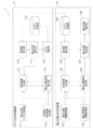
- FIG. 1 is a block diagram showing an example of a loading work support system according to a first embodiment.
- the figure which shows an example of a height map. The figure explaining the detection right or wrong of the loading position candidate by the bottom contact ratio.
- 4 is a schematic flowchart of a model generation process of the model generation processing device according to the first embodiment.
- 5 is a schematic flowchart of reinforcement learning of the model generation processing device according to the first embodiment.
- 4 is a schematic flowchart of processing of a loading position determination processing device according to the first embodiment.
- 9 is a schematic flowchart of reinforcement learning of the model generation processing device according to the second embodiment.
- FIG. 9 is a schematic flowchart of processing of a loading position determination processing device according to a second embodiment.
- the figure which shows the relationship between the number of reservations and a filling rate.
- FIG. 19 is a conceptual diagram of a result when loading is continued according to a designation of the loading position determination processing device according to the third embodiment.
- FIG. 1 is a block diagram showing an example of a hardware configuration according to an embodiment of the present invention.
- FIG. 1 is a block diagram illustrating an example of the loading operation support system according to the first embodiment.
- the loading work support system 1 according to the first embodiment includes a model generation processing device 11 and a loading position determination processing device 12.
- the model generation processing device 11 includes a loading space size acquisition unit 111, a learning baggage information generation unit 112, a state information generation unit 113, a loading position candidate detection unit 114, a model storage unit 115, an evaluation value calculation And a loading position selecting unit 117, and a model updating unit 118.
- the loading position determination processing device 12 includes a loading space information acquiring unit 121, a loading luggage information acquiring unit 122, a state information generating unit 123, a loading position candidate detecting unit 124, a model storing unit 125, An evaluation value calculating unit 126, a loading position determining unit 127, and a loading position instruction unit 128 are provided.
- the loading work support system 1 is a system for specifying a position (loading position) where an object to be loaded in a predetermined space is to be loaded.
- the model generation processing device 11 generates a loading state evaluation model for evaluating the loading state of an object in a predetermined space.
- the loading position determination processing device 12 determines the loading position of the object using the loading state evaluation model, and outputs the loading position.
- the loading operation support system 1 supports the loading operation. For example, it is assumed that the loading work support system 1 is used when the load is loaded on the carrier of the transport vehicle or when the inventory is loaded into the warehouse.
- an object to be loaded in a predetermined space is hereinafter referred to as a “luggage”, but the term does not limit the object to be loaded.
- the predetermined space may be a three-dimensional space whose size (length, width, and height) is predetermined.
- size length, width, and height
- containers, holds, storage rooms, and the like that are generally used for loading luggage are included in a predetermined space if a size that is not surrounded by a wall is defined.
- the predetermined space is hereinafter referred to as “loading space”. It should be noted that the luggage can be loaded from above, from the side, or from both directions, unless limited by a shield included in the loading space, for example, a wall of a storage room.
- the loading work support system 1 determines a loading position suitable for satisfying a desired purpose. For example, it is conceivable to load as much luggage as possible, reduce the gap between loaded luggage as much as possible, and prevent the loaded luggage from falling down as much as possible. Here, the loading work support system 1 loads as much luggage as possible into the loading space. Therefore, the loading position determination processing device 12 determines a loading position suitable for increasing the filling rate of the load in the loading space for the load to be loaded in the loading space.
- the filling rate of the loading space indicates a ratio of the load in the loading space occupied by the load. That is, the filling rate of the loading space is represented by (total volume of luggage in loading space) / (volume in loading space). Regardless of where one piece of luggage is placed, the filling rate will be the same at that point in time. become. That is, the loading position determination processing device 12 determines a loading position at which the total volume of the finally loaded luggage increases.
- the loading position determination processing device 12 does not need the size of all of the packages to be loaded when determining the loading position of the packages, and the loading position of each package is determined individually. For example, when there is a first package to be loaded and a second package to be loaded after the first package, the loading position determination processing device 12 determines the loading position of the first package, The process of determining the loading position of the second package starts. The loading position determination processing device 12 can determine the loading position of the first package even if it does not recognize the size of the second package. That is, when determining the loading position of a certain package, there is no need to have information on the subsequent package.
- each position is designated so that all the packages can be loaded efficiently.
- n is an integer greater than 1
- the device has determined the position of each of the first to n-th packages.
- the loading position determination processing device 12 does not need to know all the packages to be loaded because the loading position of each package is individually determined. For example, there is a case where an online work is performed such that the entire package to be loaded is not known and the package is loaded into the loading space upon arrival. Conventional devices cannot cope with such online work. However, in the loading operation support system 1 of the present embodiment, the worker can recognize the loading position of the arrived luggage every time the luggage arrives.
- the loading position determination processing device 12 determines the loading position of the luggage in order.
- model generation processing device 11 and the loading position determination processing device 12 may be combined into one device, and one device may perform both processes. In that case, the common components of the model generation processing device 11 and the loading position determination processing device 12 may be combined into one or may be separately provided.
- FIG. 1 shows main components that are considered necessary for generation of a loading state evaluation model and designation of a loading position using the loading state evaluation model. May be included. Further, each device and component may be subdivided or may be integrated into one.
- the loading position determination processing device 12 includes a loading space information acquiring unit 121, a loading luggage information acquiring unit 122, a state information generating unit 123, a loading position candidate detecting unit 124, and a model storing unit 125. And a second device including a loading position determining unit 127 and a loading position instructing unit 128.
- the loading position determination processing device 12 includes a third device including a loading space information acquiring unit 121, a loading luggage information acquiring unit 122, and a state information generating unit 123, and a loading position candidate detecting unit. It is also conceivable that the device is divided into a fourth device including a storage device 124, a model storage unit 125, an evaluation value calculation unit 126, a loading position determination unit 127, and a loading position instruction unit 128. In this case, it is conceivable that a height map described later is calculated by the third device and transmitted to the fourth device, and the fourth device determines and outputs a loading position based on the height map.
- the components exist in an external device that is neither the model generation processing device 11 nor the loading position determination processing device 12, and the model generation processing device 11 and the loading position determination processing device 12
- the processing result by the element may be obtained.
- the loading position candidate detection unit 124 may be provided in a device different from the loading position determination processing device 12 to distribute the processing load of the loading position determination processing device 12.
- the model generation processing device 11, the loading position determination processing device 12, the information acquisition source (not shown), and the information output destination (not shown) transmit and receive data via a communication network or the like. Is possible.
- the model generation processing device 11 generates a loading state evaluation model by performing reinforcement learning. Therefore, the model generation processing device 11 can be said to be a reinforcement learning device.
- Value @ Iteration can be used as reinforcement learning.
- the Value Iteration includes various methods such as TD (Temporal Difference Learning), Q-learning, and DQN (Deep Q-Network), and any method may be used. An example of a component for executing the reinforcement learning will be described below.
- the loading space size acquisition unit 111 acquires the size of the loading space from outside.
- the size may be obtained from a user via an input interface built in the model generation processing device 11, or may be obtained from an external device.
- the size of the loading space is set as a range in which luggage can be loaded. Note that the loadable range of the load may be smaller than the size of the loading space.
- the learning luggage information generating unit 112 generates luggage information used for reinforcement learning for generating a loading state evaluation model.
- this information is referred to as “learning baggage information”.
- the learning baggage information is test data, and includes the size of each baggage and the order of arrival of the baggage. That is, the learning baggage information generating unit 112 determines the size of each baggage and the order of arrival of the baggage. In the present embodiment, the order of arrival of the packages matches the order of loading the packages.
- the package is a rectangular parallelepiped, and the size of the package is represented by length, width, and height.
- the size of each package may be determined based on sample data such as a record of packages actually loaded so far, or may be determined randomly. If the size of the package is divided into a plurality of types according to the standard or the like, the size may be selected from those types.
- the information such as the record and the standard may be registered in the learning baggage information generating unit 112 in advance, or may be acquired from outside by the learning baggage information generating unit 112.
- the state information generation unit 113 generates state information relating to the loading state of the package in the loading space.
- information relating to the height of the entire package loaded in the loading space is generated as state information.
- the information is described as “height map”.
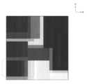
- FIG. 2 is a diagram illustrating an example of the height map.
- the height map in the example of FIG. 2 is a top view showing the loading space as viewed from above, and the height of the upper end of the uppermost luggage present in each section predetermined in the loading space is indicated by a color. It is also a heat map indicated by shading. The darker color indicates that the top of the package is higher.
- the height of the upper end of the uppermost luggage present in the section is defined as "section height”. That is, the height map indicates the height of the entire loaded luggage in each section. In this manner, the height map can indicate the height of the entire package loaded in the loading space.
- the shape of the section is rectangular according to the assumed rectangular parallelepiped luggage.
- each section is generated by partitioning the floor surface of the loading space into a grid, but the method of generating the section may be determined as appropriate. It is assumed that the size of the section is predetermined in consideration of the processing load, the estimation accuracy, and the like. However, the state information generation unit 113 changes the size according to the designated value input to the model generation processing apparatus 11. You may. Further, the size of the section may be different for each section.
- the end of each package is adjusted so as to coincide with the boundary of the section. For example, if the size of the package is not uniform, the boundary line and the end of the package cannot completely match, so the state information generating unit 113 rounds the size of the package to fit the section, and Generate a map. Note that the learning baggage information generating unit 112 may generate a baggage size that fits the section. When the size of the package is any of the predetermined standard sizes, the size of the section may be adjusted so that the boundary line and the end of the package can completely match.
- the height map is not limited to image data.
- the height map may be represented as data obtained by combining information indicating the position of a section (for example, a row number and a column number) and the height of the package in the section. That is, the height map may be in any format as long as the height in each section can be recognized.
- the state information generation unit 113 determines the height when the package is loaded on any of the loading position candidates. A map is generated for each loading position candidate. The height map is described as “height map candidate”.
- the state information generating unit 113 converts the height map candidate corresponding to the loading position into the height at the time of loading the next package. Map. Thus, the height map is updated.
- the height map candidate can be created by increasing the height of the section for the determined loading position or each section included in the candidate loading position by the height of the package to be loaded this time. It is.
- the loading position candidate detection unit 114 detects a position at which a load can be loaded using the learning baggage information and the height map.
- the detected position is described as “loading position candidate”.
- a position where the contact ratio of the bottom surface is equal to or larger than a threshold is set as a loading position candidate.
- the contact ratio of the bottom surface indicates the ratio of the area of contact with the floor surface of the loading space or the top surface of another package to the bottom surface of the package. That is, it means (area of contact area) / (area of entire bottom surface).
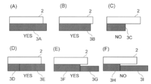
- FIG. 3 is a diagram for explaining whether or not a loading position candidate is detected based on the bottom surface contact ratio.
- the positional relationship between the package 2 to be loaded and the package 3 already loaded (3A to 3I) is shown. Whether or not it is detected as a loading position candidate is indicated by YES or NO.
- the position of the package 2 in FIGS. 3A and 3B is detected as a loading position candidate because the bottom surface contact ratio is large.
- the position of the package 2 in FIG. 3C is not detected as a loading position candidate because the bottom surface contact ratio is small.
- the package 2 is in contact with both the package 3D and the package 3E. In such a case, the bottom surface contact ratio is calculated without distinguishing the luggage 3D and the luggage 3E.
- the position of the package 2 in FIG. 3D is detected as a loading position candidate because the bottom surface contact ratio is large.
- the package 2 is in contact only with the package 3F.
- the position of the package 2 is It is detected as a loading position candidate.
- the package 2 is in contact only with the package 3H, and the bottom contact ratio with the package 3H is small. The position of the package 2 is not detected as a loading position candidate.
- the loading position candidate detection unit 114 searches for a position at which the bottom surface contact ratio is equal to or greater than the threshold based on the height map, and sets the detected position as a loading position candidate. In addition, when a luggage is placed at the detected loading position candidate and a section having a height exceeding the upper limit comes out, it is prevented from being detected as a loading position candidate.
- the conditions for determining the loading position candidates as described above may be appropriately determined.
- the loading position candidate detection unit 114 may rotate the load when determining the loading position. That is, the length, width, and height of the load may be switched. Note that some luggage cannot be turned into an inverted state. For this reason, a rotation direction may be restricted such that rotation in which the rotation axis is parallel to the vertical direction is permitted and other rotations are prohibited.
- the model storage unit 115 stores the loading state evaluation model.
- the loading state evaluation model is a model that outputs an evaluation value for the loading state when information on the loading state of the package in a predetermined space is input.
- the evaluation value based on the loading state evaluation model is a value relating to the total capacity of loads that can be loaded from the loading state. What is used as the evaluation value may be appropriately determined according to the purpose. For example, a value related to the load capacity of the baggage, such as information on the filling rate of the baggage in the predetermined space, information on the total capacity of the baggage, information on the available capacity for loading the package, information on the total capacity of the loadable baggage, etc. It can be used as an evaluation value.
- the evaluation value may be calculated using information on the loading capacity of the baggage and another information.
- a value relating to the total capacity of loads that can be loaded is used as the evaluation value
- a higher evaluation value means that the total capacity is larger and there is still room to load the loads.
- a height map candidate with a high evaluation value calculated by the learned loading state evaluation model is continuously selected from a plurality of height map candidates, a large amount of luggage is loaded, and as a result, the loading space The filling rate can be increased. Therefore, the evaluation value based on the loading state evaluation model indicates whether the input loading state is a state suitable for increasing the filling rate of the load in the predetermined space. Reinforcement learning is performed so that the evaluation value by the loading state evaluation model becomes appropriate.
- the form of the loading state evaluation model may be changed according to the method of reinforcement learning.
- An evaluation function that outputs an evaluation value by combining the feature amounts of the loading state may be used, or a neural network such as a convolutional neural network (CNN) used in DQN may be used.
- CNN convolutional neural network
- DQN convolutional neural network
- the evaluation value calculation unit 116 inputs the height map candidate to the loading state evaluation model, and obtains an evaluation value from the loading state evaluation model.
- the evaluation value calculation unit 116 may adjust the evaluation value based on the loading state evaluation model. Even if the evaluation value calculated by the evaluation value calculation unit 116 does not completely match the evaluation value based on the loading state evaluation model. Good. Thus, the evaluation value calculation unit 116 calculates an evaluation value for the height map candidate using the loading state evaluation model.
- the loading position selection unit 117 selects one of the loading position candidates based on a predetermined policy and sets it as the loading position of the currently loaded package.
- the policy is, for example, a greedy method of selecting the loading position candidate having the largest evaluation value, randomly selecting the loading position candidate with the probability ⁇ , and selecting the loading position candidate having the largest evaluation value with the probability 1 ⁇ . ⁇ -greedy is considered.
- the model updating unit 118 updates the parameters of the loading state evaluation model in the model storage unit 115 by evaluating the validity of the evaluation value related to the selected loading position.
- the updating method may be appropriately determined according to the type of reinforcement learning.
- the parameter may be updated by feeding back the filling rate at the time when the load cannot be loaded, evaluating the validity of the evaluation value with respect to the loading state at each time when the load is loaded.
- the loading state evaluation model can calculate an appropriate evaluation value.
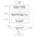
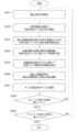
- FIG. 4 is a schematic flowchart of the model generation process of the model generation processing device 11 according to the first embodiment.
- the loading space size acquisition unit 111 acquires the size of the loading space, that is, the vertical, horizontal, and height limit values (S101).
- the learning baggage information generating unit 112 generates test data (S102).
- the test data includes the size of the package and the order of the package. For example, the sizes of the first to n-th packages are determined in advance.
- the constant n is set to a number that is sufficiently large such that all loads cannot be loaded in the loading space.
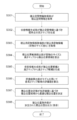
- FIG. 5 is a schematic flowchart of reinforcement learning of the model generation processing device 11 according to the first embodiment.
- the loading state is initialized to start a new episode of reinforcement learning (S201).
- the initialization means that the loading operation of the luggage starts from an initial state where the luggage does not exist in the loading space. That is, after the initialization, the process of determining the loading position of the first package is started.
- the state information generator 113 generates a current height map of the loading space (S202).
- the present time may be any time from when the previous luggage is loaded to before the current luggage is loaded.
- the present time when loading the first luggage may be any time from the start of the work to before loading the first luggage.
- the height map is the same as the top view of the loading space.
- the state information generation unit 113 determines the loading position of the (k ⁇ 1) -th package.
- the height map candidate corresponding to the loaded position may be used as the height map in the process of determining the loading position of the k-th package.
- the loading position candidate detection unit 114 detects a loading position candidate based on the size of the baggage to be loaded this time and the current height map updated in the process of S202 (S203).
- the state information generation unit 113 generates, for each of the calculated loading position candidates, a height map when the calculated loading position candidate is loaded with the package to be loaded this time, that is, a height map candidate ( S204).
- the evaluation value calculation unit 116 calculates an evaluation value from each height map candidate using the loading state evaluation model (S205).
- the loading position selection unit 117 selects one of the plurality of loading position candidates based on the policy (S206).
- the model updating unit 118 updates the model (S207). Note that, depending on the method of reinforcement learning, the process of S207 may not be performed every time a load is loaded. In that case, the process of S207 is omitted. For example, when the loading positions of the first to fourth packages are determined, S207 is omitted, and when the loading position of the fifth package is determined, the first to fifth packages are determined.
- the model may be updated based on the loading position of. Further, when the end condition of the episode or the test data is satisfied, the model may be updated based on the loading position of the luggage not used for updating the model.
- the process returns to S202, and the process for the next package to be loaded is started. If the condition for ending the episode is satisfied (YES in S208) but the condition for ending the test data is not satisfied (NO in S209), the process returns to the initialization of the state to start a new episode (S201). .
- the condition for ending the episode is satisfied (YES in S208) and the condition for ending the test data is also satisfied (YES in S209), the reinforcement learning using the test data ends.
- the condition for ending the episode may be, for example, a case where the evaluation value falls below the threshold value because the evaluation value decreases as the luggage is loaded (as the number of times the loading position determination process is performed increases). The episode may end when the next luggage cannot be loaded.
- the termination condition for the test data may be appropriately determined based on the number of episodes executed, the filling rate at the end of the episode, and the like.
- the loading space information acquisition unit 121 acquires information on the loading space.
- the information is hereinafter referred to as “loading space information”.
- the loading space information includes at least the size of the loading space.
- information on the position of the already loaded luggage may be included in the loading space information. This is because the loading position determination processing device 12 can specify the loading position of the next package even when the package is present in the loading space.
- the loading space information may be obtained from a user via an input interface built in the model generation processing device 11, or may be obtained from an external device.
- the loading luggage information acquisition unit 122 acquires information on the luggage to be loaded.
- the information is hereinafter referred to as “loading luggage information” to distinguish it from learning luggage information.
- the loading baggage information includes the size of the baggage to be loaded this time.
- Loading baggage information may be obtained from a user via an input interface built in the model generation processing device 11 or may be obtained from an external device.
- the state information generation unit 123 of the loading position determination processing device 12 may be the same as the state information generation unit 113 of the model generation processing device 11, and generates a height map and a height map candidate corresponding to the loading position candidate. .
- the state information generation unit 123 of the loading position determination processing device 12 may generate a height map from an image in the loading space.
- Known measurement software that can determine the height from the image using a technique such as triangulation or a stereo camera may be used. That is, the image in the loading space may be included in the loading space information as information on the position of the already loaded luggage. Alternatively, for example, information on the height of already loaded luggage may be acquired by a depth camera or the like, and the information may be transmitted to the state information generation unit 123. Further, the information may be used as test data for generating a loading state evaluation model of the model generation device.
- the loading position candidate detection unit 124 of the loading position determination processing device 12 may be the same as the loading position candidate detection unit 114 of the model generation processing device 11, and the next luggage can be loaded using the height map. Calculate the correct position.
- the model storage unit 125 of the loading position determination processing device 12 acquires and stores the learned loading state evaluation model from the model generation processing device 11.
- the model storage unit 125 of the loading position determination processing device 12 stores a plurality of loading state evaluation models corresponding to different loading spaces, and when the loading space is designated, the specified loading condition is determined.
- the loading state evaluation model corresponding to the loading space may be transmitted.
- the evaluation value calculation unit 126 of the loading position determination processing device 12 uses the loading state evaluation model stored in the model storage unit 125 as a program module that is a part of software, and calculates an evaluation value for each height map candidate. calculate.
- the evaluation value calculation unit 126 may be the same as the evaluation value calculation unit 116 of the model generation processing device 11.
- the evaluation value calculation unit 116 obtains the loading space information obtaining unit 121 from the plurality of loading state evaluation models.
- the loading state evaluation model corresponding to the loading space according to the loading space information is extracted from the model storage unit 115 based on the size of the loading space, the identifier of the loading space, and the like. Therefore, the identifier of the loading space may be included in the loading space information.
- the loading position determination unit 127 of the loading position determination processing device 12 determines the loading position candidate having the highest evaluation value among the loading position candidates as the loading position of the currently loaded package.
- the loading position instruction unit 128 outputs (instructs) information relating to the loading position to an output destination.
- the loading position may be represented by coordinates or may be represented by an image such as a height map.
- the output destination is not particularly limited.
- the loading position may be displayed on a display device such as a monitor to inform the worker of the loading position.
- a control device such as a robot arm, it is also possible to control the robot arm to load a load at the loading position.
- the actual loading operation can be supported.
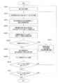
- FIG. 6 is a schematic flowchart of the processing of the loading position determination processing device 12 according to the first embodiment.
- the loading space information acquiring unit 121 acquires loading space information (S301), and the state information generating unit 123 generates a current height map based on the loading space information (S302).
- the loading luggage information acquisition unit 122 acquires loading luggage information (S303).
- the loading position candidate detection unit 124 detects a loading position candidate from the size of the package to be loaded this time and the height map included in the loading package information (S304).
- the state information generation unit 123 generates, for each of the calculated loading position candidates, a height map when the current luggage is loaded on the calculated loading position candidate, that is, a height map candidate (S305). .
- the evaluation value calculation unit 126 calculates the evaluation value of each height map candidate using the loading state evaluation model (S306). Then, the loading position determination unit determines the loading position candidate relating to the height map candidate having the largest evaluation value as the optimal loading position (S307). Finally, the loading position indicating unit 128 outputs the determined loading position (S308), and the flow ends.
- the loading position of the package is selected from one or more possible loading positions based on the evaluation value. Therefore, the loading position is not determined heuristically. For example, in the heuristic approach, the load is placed at the corner of the loading space or in close contact with the load already loaded. However, in the present embodiment, this is not the case, and the first package may be placed near the center of the loading space.
- the loading state evaluation model for evaluating the loading state is generated by performing the reinforcement learning using the height map. Then, using the loading state evaluation model, the loading position is specified for each package.
- the loading state evaluation model for evaluating the loading state is generated by performing the reinforcement learning using the height map. Then, using the loading state evaluation model, the loading position is specified for each package.
- the packages are loaded in the order of arrival of the packages.
- the arriving luggage can be held without being loaded, for example, when the luggage can be temporarily stored.
- the luggage does not necessarily have to be loaded in the order of arrival.
- by changing the loading order it is considered possible to load the luggage more efficiently.
- FIG. 7 is a block diagram showing an example of the loading operation support system 1 according to the second embodiment.
- the model generation processing device 11 further includes a reservation determination unit 119
- the loading position determination processing device 12 further includes a reservation determination unit 129. The description of the same points as in the first embodiment will be omitted.
- the loading position candidate detection unit 114 of the model generation processing device 11 and the loading position candidate detection unit 124 of the loading position determination processing device 12 perform loading not only on the presently provided luggage but also on the pending luggage.
- This embodiment differs from the first embodiment in that the insertion position candidate is detected.
- the pending luggage and the luggage given this time are luggage candidates to be loaded this time, and the loading position candidate detection unit 114 of the present embodiment detects a luggage position candidate for each luggage candidate.
- the luggage candidates to be loaded this time are described as “load luggage candidates”.
- the method of detecting a loading position candidate is the same as in the first embodiment.
- the suspension determination unit 119 of the model generation processing device 11 and the suspension determination unit 129 of the loading position determination processing device 12 determine whether to suspend the determination of the loading position. If the evaluation values of all loading position candidates do not satisfy the conditions for being selected as loading positions, it may be determined to be “pending”. For example, if all values obtained by subtracting the evaluation value for the height map candidate from the current evaluation value of the height map are equal to or greater than a certain value, that is, if the evaluation of the loading state suddenly worsens, It is more likely not to be loaded. Therefore, in such a case, the determination of the loading position may be suspended.
- the evaluation value calculation unit 116 of the model generation processing device 11 and the evaluation value calculation unit 126 of the loading position determination processing device 12 may be the same as in the first embodiment. However, in the second embodiment, there may be a case where there are a plurality of packages that are the loading baggage candidates. These packages may be equally selected from the evaluation values based on the height map candidates, or certain packages may be preferentially selected. Alternatively, the evaluation value calculation unit 116 and the evaluation value calculation unit 126 may assign weights for selecting packages to be loaded from a plurality of packages according to purposes.
- the luggage including, for a value that indicates the total capacity of the loading possible luggage, to compare the load between the different sizes Will be possible.
- luggage b i a loading position candidates p j in embarked's state S (b i, p j) the loading state evaluation model in V M (S (b i, p j))
- the evaluation value calculator 116 and the evaluation value calculation unit 126, V (S (b i, p j)) + volume (b i) values may be evaluation values obtained by.
- the larger or smaller the size of the baggage the higher the possibility of being loaded first.
- the evaluation value calculation unit 116 and the evaluation value calculation section 126 it is conceivable to add the value of the penalty function penalty (b i) the (penalty value) of the evaluation value by the loading condition evaluation model. That is, the evaluation value calculation unit 116 and the evaluation value calculation unit 126, V (S (b i, p j)) + penalty (b i), or, V (S (b i, p j)) + volume (b i) + penalty value obtained by (b i) may be calculated as an evaluation value.
- Penalty function penalty (b i) is the calculated zero or negative value depending on the luggage loading. For example, the value is 0 for the baggage that has arrived most recently (baggage that has not been held), but a negative value is calculated for the baggage that has been held. The negative value may be adjusted appropriately. This increases the possibility that the most recently arrived luggage (luggage that is not on hold) will be loaded.
- the evaluation value may be processed for the purpose of selecting the load to be loaded and reducing the number of the stored packages, and the processing method is not limited to the above example.
- FIG. 8 is a schematic flowchart of reinforcement learning of the model generation processing device 11 according to the second embodiment.
- the processing of S401 and S402 is the same as the processing of S201 and S202 of the first embodiment, respectively.
- the processing in S403 is partially different from the processing in S203, and the loading position candidate detection unit 114 detects a loading position candidate for each piece of package that has been set as a loaded package candidate (S403). Note that, when the hold is selected in the last process of determining the loading position of the baggage, the detection of the baggage candidate of the held baggage is omitted because the baggage candidate of the held baggage has already been detected. However, only the loaded luggage candidate of the current luggage may be detected.
- the processing of S404 and S405 is the same as the processing of S204 and S205 of the first embodiment, respectively, and the evaluation value of each height map candidate is calculated.
- the loading position selection unit 117 adds the package given this time to the loading candidate (S407).
- the process of determining the loading position of the next package is started. If the condition for suspension is not satisfied (NO in S406), the loading position selection unit 117 selects a loading position from the loading position candidates, similarly to S206 in the first embodiment (S408). . Subsequent processing and branching are the same as in the first embodiment.
- the process of S409 for updating the model may be performed for a plurality of packages at once instead of every time the packages are loaded.
- FIG. 9 is a schematic flowchart of the processing of the loading position determination processing device 12 according to the second embodiment.
- the processing from S501 to S503 is the same as the processing from S301 to S303 in the first embodiment, respectively.
- the processing in S504 is partly different from the processing in S304, and the loading position candidate detection unit 124 detects a loading position candidate for each loaded luggage candidate (S403).
- the processing of S505 and S506 is the same as the processing of S305 and S306 of the first embodiment, respectively, and the evaluation value of each height map candidate is calculated. If the calculated evaluation value of the height map candidate satisfies the condition for suspension (YES in S507), the loading position determination unit 127 is given this time without determining the loading position as suspension. The loaded luggage is added to the loading luggage candidate (S508). If the conditions for suspension are not satisfied (NO in S406), the loading position determination unit determines the loading position as in the first embodiment (S509). Then, the loading position instructing section 128 outputs the content of the decision, the hold or the loading position (S510).
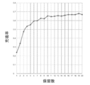
- FIG. 10 is a diagram illustrating the relationship between the number of reservations and the filling rate.
- the horizontal axis indicates the maximum number that can be reserved, and the vertical axis indicates the final filling rate of the loading space.
- the shape of the graph in FIG. 10 naturally changes depending on the distribution of the size of the load, the size of the loading space, and the like, but the filling rate tends to increase as the number of holdings increases from zero. Therefore, it is understood that the luggage can be efficiently loaded when the holding is enabled.
- the filling rate does not improve so much, which indicates that the number of reservations need only be a fixed number.
- the final filling rate of the loading space can be improved by enabling the holding.
- the number of holdings is several, it is sufficiently effective, and it is not necessary to hold all the packages.
- the load may eventually be stair-like stacked.
- the density decreases in order from left to right. This indicates that the packages are stacked in steps.
- the stability of the load may be emphasized. Therefore, in the third embodiment, the stability of the load is also considered without evaluating the loading state based only on the filling rate. The description of the same points as in the first embodiment will be omitted.
- FIG. 1 or FIG. 8 is also a schematic configuration diagram in the third embodiment. The description of the same points as in the first embodiment will be omitted.
- the condition for determining the loading position candidate is relaxed, and a condition for enabling loading is provided even when the condition regarding the bottom surface contact ratio is not satisfied.
- a position where the side surface that does not intersect with the contact area on the bottom surface contacts the side wall of the loading space or other luggage is allowed as a loading position candidate.
- positions where the contact ratio of the side surface may be allowed as a loading position candidate. Good.
- the position where the side surface that does not intersect with the contact region of the bottom surface comes into contact with the side wall of the loading space directly or via another load is set at the loading position. You may make it allow as a position candidate.
- FIG. 11 is a diagram for explaining whether or not a loading position candidate is detected by side contact. The positional relationship between the package 2 to be loaded and the package 3 (3J to 30) already loaded is shown. Whether or not it is detected as a loading position candidate is indicated by YES or NO.
- FIG. 11 (A) although the contact ratio of the bottom of the package 2 with the package 3J is small, the package 2 is in contact with the package 3K on the side surface that does not intersect with the contact area of the bottom surface. However, the load 3K is not in contact with the side wall 4 of the loading space. In such a case, if the loading space sways, the luggage 3N and luggage 2 may collapse to the right. Therefore, the position of the package 2 in FIG. 11A is not detected as a loading position candidate.
- FIG. 11 (B) although the contact ratio of the bottom surface of the baggage 2 and the baggage 3M is small, the baggage 2 is in contact with the baggage 3N on the side surface that does not intersect with the contact area of the bottom surface.
- the load 3N is in contact with the side wall 4 of the loading space. In such a case, even if the loading space sways, the load 3N is supported by the side wall 4 and is therefore less likely to collapse. Therefore, the position of the package 2 in FIG. 11B may be detected as a loading position candidate.
- the model generation processing device 11 of the third embodiment may generate a loading state evaluation model so as to calculate an evaluation value in consideration of the stability of the loading state of the load.
- the loading state evaluation model of the embodiments described above the height map candidates were used as input information, but information indicating the stability of the loading state of the package is added to the input information, and the loading state evaluation model is used. Can be generated.
- a model for calculating an evaluation value for stability may be generated from information indicating the stability of the loading state of the package, separately from the loading state evaluation model of the embodiments described above. In this case, the evaluation value calculation unit calculates the evaluation value based on the sum of the evaluation value of the loading state evaluation model and the evaluation value of the model for calculating the evaluation value for stability.
- a step map obtained by processing a height map can be considered. For example, for each section of the height map, the sum of logical values representing the comparison of the height with each of the adjacent sections is calculated. For example, it is conceivable that the logical value is 1 when the height is higher than the adjacent section, 0 when the height is the same, and -1 when the height is lower. Thus, the absolute value of the sum indicates the difference in height between the adjacent sections.
- the sum is defined as a “step”, and information indicating a step in each section of the entire loaded luggage is described as a “step map”.
- the step map can be considered as information indicating the stability of the loading state of the load.
- This step map is further added to the input information of the loading state evaluation model, and reinforcement learning is performed so that many rewards can be finally obtained even when the height of each section is uniform. This allows the loading state evaluation model to evaluate the loading state suitable for increasing the filling rate of the load in the predetermined space and equalizing the height in each section.
- the state information generation unit 113 and the state information generation unit 123 may generate the height map and then generate the step map from the height map.
- the state information generating unit 113 and the state information generating unit 123 generate a step map candidate in the same manner as the height map candidate and together with the height map candidate.
- the evaluation value calculation unit 116 and the evaluation value calculation unit 126 input the generated step map candidates together with the height map candidates to the loading state evaluation model, and acquire evaluation values. Other points are the same as those of the previous embodiments.
- the step map may be image data such as a heat map, or may be data obtained by combining information indicating the position of a section (for example, a row number and a column number) and a sum of logical values in the section. May be represented as
- step map candidate is set to “height map candidate”. It should be read as “step map candidate", and a description thereof will be omitted.
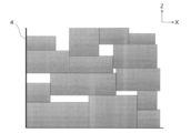
- FIG. 12 is a conceptual diagram of a result when loading is continued according to the designation of the loading position determination processing device according to the third embodiment. It can be seen that the luggage is not stacked in a staircase and the stability has increased.
- the product by considering the contact on the side surface, and by using the step map to calculate the evaluation value in consideration of not only the filling rate but also the stability, the product It is possible to improve the stability of the insertion state.
- FIG. 1 or FIG. 7 is also a schematic configuration diagram in the fourth embodiment. The description of the same points as the above embodiments is omitted.
- the baggage information for learning and the baggage information for loading further include the weight of the baggage.
- the learning baggage information generating unit 112 further determines the weight of the baggage together with the size of the baggage as test data.
- the weight is used, but the density may be considered instead of the weight. In this case, in this description, the weight (weight) may be read as the density.
- the state information generation unit 113 and the state information generation unit 123 perform the same process as generating the height map except that the weight of the package is used instead of the height of the package. And generating information indicating the weight of each section defined in the predetermined space. The information is described as “weight map”.
- the weight map is further added as input information, and reinforcement learning is performed so that a large amount of reward can be obtained even when the weight in each section is finally uniform.
- This allows the loading state evaluation model to evaluate the loading state suitable for increasing the filling rate of the load in the predetermined space and equalizing the height in each section.
- the state information generation unit 113 and the state information generation unit 123 generate a weight map candidate for the loading position candidate from the loading position candidate and the weight map in the same manner as the height map candidate and together with the height map candidate. I do.
- the loading position candidate detection unit 114 and the loading position candidate detection unit 124 detect loading position candidates based on the height map and the weight map.
- the height of each section does not exceed the corresponding upper limit when the baggage is loaded.
- the weight of each section does not exceed the corresponding upper limit.
- an upper limit value of the total weight of the stacked luggage may be set for each luggage.
- the upper limit of the total weight of the stacked luggage may be different for each luggage according to the size of the luggage. For example, it is conceivable that the upper limit value is increased for high-density packages, and the upper limit value is reduced for low-density packages.
- a value obtained by dividing the total weight of the loaded luggage by the area of the upper surface of the luggage, that is, the upper limit of the pressure applied to the upper surface of the luggage may be provided.
- the evaluation value calculation unit 116 and the evaluation value calculation unit 126 input the generated weight map candidates together with the height map candidates into the loading state evaluation model, and acquire evaluation values.
- the loading state evaluation model of the fourth embodiment is an evaluation value that takes into account the weight of the section.
- a model for calculating an evaluation value from the weight map candidate is generated separately from the loading state evaluation model of the previous embodiment, and the model is added to the loading state evaluation model of the previous embodiment.
- a new loading state evaluation model may be generated. Other points are the same as those of the previous embodiments.
- the weight map may be image data, or may be information obtained by combining information indicating the position of a section (for example, a row number and a column number) and the total weight of luggage in the section. May be represented.
- the flow of the present embodiment is omitted because “height map” may be replaced with “height map and weight map” and “height map candidate” may be replaced with “height map candidate and weight map candidate”. I do.
- the lower baggage by using the weight map to calculate the evaluation value in consideration of not only the filling rate but also the weight of each section, the lower baggage can weigh the upper baggage. This can prevent the situation of being crushed.
- the state information generation unit 113 uses the “height map” indicating the height of the load relative to the bottom surface as an example of the state information regarding the load state of the load in the loading space. It may be used. For example, when the upper surface of the loading space is shielded and only a part of the side surface is open, information on the depth of the entire package based on the open surface may be used as the state information. That is, a height map for the surface facing the opening surface, in other words, a depth map may be used.
- the loading position candidate detection unit 114 sets a position where the contact ratio of the side surface and the bottom surface of the package on the opposite surface side is equal to or greater than a threshold value as a loading position candidate, and the state information generation unit 113 detects the loading position candidate.
- information on the depth (depth map candidate) when the package is loaded on any of the loading position candidates is generated for each loading position candidate. Is also good.
- the depth map and the depth map candidate may be a heat map indicating the depth of the depth based on the opening surface in shades of color, or information indicating the position of the section.
- the data may be a combination of the depth of the baggage in the section.
- the evaluation value calculation unit 126 calculates an evaluation value of information on depth for each loading position candidate using the loading state evaluation model.
- As the evaluation value information on the filling rate of luggage in the loading section and the total capacity of the loadable objects may be used.
- the height map for the bottom surface of the loading space may be generated and used.
- the loading position candidate detection unit 114 detects the loading position candidate using the contact ratio of the bottom surface or the like, but may determine the loading position candidate using other information. For example, when the intensity of an already loaded object is low and the object cannot be placed on the upper surface, the upper surface of the object may be controlled so as not to be detected as a loading position candidate. Further, the loading position candidates may be determined according to the weight of the loading target object. As described above, the loading position candidate detection unit 114 may determine the loading position according to the characteristics (strength, weight, etc.) of each object.
- a dedicated electronic circuit that is, hardware
- IC integrated circuit
- a plurality of components may be realized by one electronic circuit, one component may be realized by a plurality of electronic circuits, or one component and one electronic circuit may be realized.
- at least a part of the above-described embodiment may be realized by executing software (program).
- a general-purpose computer device is used as basic hardware, and a central processing unit (CPU: Central Processing Unit) mounted on the computer device, a processor (processing circuit, Processing Circuit, etc.) such as an image processing device (GPU: Graphics Processing Unit).
- CPU Central Processing Unit
- the processing of the above-described embodiment can be realized by causing the processing (processing @ circuit) to execute the program.
- the processor processing circuit
- the processor is configured to execute each process of each device by executing the program.
- the computer can read the dedicated software stored in the computer-readable storage medium, and the computer can be used as the device of the above embodiment.
- the type of storage medium is not particularly limited.
- the computer can be used as the device of the above embodiment by installing the dedicated software downloaded via the communication network.
- information processing by software is specifically implemented using hardware resources.
- FIG. 13 is a block diagram illustrating an example of a hardware configuration according to an embodiment of the present invention.
- Each device of the work support system includes a processor 51, a main storage device 52, an auxiliary storage device 53, a network interface 54, and a device interface 55, and these are connected to a computer device 5 via a bus 56.
- the computer device 5 in FIG. 13 includes one component, but may include a plurality of the same components.
- one computer device 5 is shown.
- software may be installed in a plurality of computer devices, and each of the plurality of computer devices may execute a part of processing different from the software. .
- the processor 51 is an electronic circuit (processing circuit) including a computer control device and an arithmetic device.
- the processor 51 performs arithmetic processing based on data and programs input from each device of the internal configuration of the computer device 5 and outputs an arithmetic result and a control signal to each device and the like.
- the processor 51 controls each component configuring the computer device 5 by executing an OS (Operating System), an application, and the like of the computer device 5.
- the processor 51 is not particularly limited as long as it can perform the above processing. It is assumed that the components of the model generation processing device 11 and the loading position determination processing device 12 other than the model storage unit 115 and the model storage unit 125 are realized by the processor 51. Further, when the loading state evaluation model is read, the processor 51 functions to output output information such as an evaluation value from input information stored in the main storage device 52 or the auxiliary storage device 53.
- the main storage device 52 is a storage device for storing instructions executed by the processor 51, various data, and the like, and the information stored in the main storage device 52 is directly read by the processor 51.
- the auxiliary storage device 53 is a storage device other than the main storage device 52. Note that these storage devices mean any electronic component capable of storing electronic information, and may be a memory or a storage.
- the memory includes a volatile memory and a non-volatile memory, and any of them may be used.
- the model storage unit 115 may be realized by the main storage device 52 or the auxiliary storage device 53. That is, the model storage unit 115 may be a memory or a storage.
- the network interface 54 is an interface for connecting to the communication network 6 wirelessly or by wire.
- the network interface 54 may be one that conforms to an existing communication standard. From the network interface 54, the computer device 5 and the external device 7A can be connected via the communication network 6.
- the device interface 55 is an interface such as a USB that is directly connected to the external device 7B. That is, the connection between the computer device 5 and the external device 7 may be via a network or directly.
- the external device 7 (7A and 7B) may be any of a device outside the loading work support system 1, a device inside the loading work support system 1, an external storage medium, and a storage device.
Abstract
事前に積込予定の荷物を全て把握していなくとも、適切な積込位置の決定に関する処理を行うことが可能な装置を提供する。本発明の一実施形態は、メモリと、少なくとも1つの処理回路と、を備える。前記少なくとも1つの処理回路は、積込予定の第1物体が複数の積込位置候補のいずれかに積み込まれたとした場合の状態情報を生成することと、所定空間における物体の積込状態に関する状態情報が入力されると、前記所定空間における物体の積込状態に対する評価値を出力する積込状態評価モデルに、前記積込位置候補の状態情報を入力して評価値を取得することと、を実行するよう構成される。
Description
本発明は、情報処理装置、モデル生成処理装置、および情報処理方法に関する。
物流業界にとって、コンテナ、トラックの荷台といった荷物を積み込むための空間に、いかにして荷物を積み込むかは、非常に重要な課題である。近年では、各荷物の最適な積込位置がコンピュータにより判断されることも少なくない。
コンピュータが各荷物の最適な積込位置を判断する従来方式では、積込予定の荷物の個数、各荷物のサイズが事前に把握されていることが前提となっている。例えば、コンピュータは、各荷物の積込位置の組み合わせが最適となるようなアルゴリズムを用いて、積込位置を決定する。しかし、宅配便などを取り扱う場合、作業時間、作業スペースなどの観点から、荷物が到着する度に荷物を積み込むといったオンライン対応を行うことも多い。そのような場合には、各荷物の最適な積込位置は依然として作業員の経験により判断されている。
事前に積込予定の荷物を全て把握していなくとも、適切な積込位置の決定に関する処理を行うことが可能な装置を提供する。
本発明の一実施形態は、メモリと、少なくとも1つの処理回路と、を備える。前記少なくとも1つの処理回路は、積込予定の第1物体が複数の積込位置候補のいずれかに積み込まれたとした場合の状態情報を生成することと、所定空間における物体の積込状態に関する状態情報が入力されると、前記所定空間における物体の積込状態に対する評価値を出力する積込状態評価モデルに、前記積込位置候補の状態情報を入力して評価値を取得することと、を実行するよう構成される。
以下、図面を参照しながら、本発明の実施形態について説明する。
(第1の実施形態)
図1は、第1の実施形態に係る積込作業支援システムの一例を示すブロック図である。第1の実施形態に係る積込作業支援システム1は、モデル生成処理装置11と、積込位置決定処理装置12と、を備える。
図1は、第1の実施形態に係る積込作業支援システムの一例を示すブロック図である。第1の実施形態に係る積込作業支援システム1は、モデル生成処理装置11と、積込位置決定処理装置12と、を備える。
モデル生成処理装置11は、積込空間サイズ取得部111と、学習用荷物情報生成部112と、状態情報生成部113と、積込位置候補検出部114と、モデル記憶部115と、評価値算出部116と、積込位置選択部117と、モデル更新部118と、を備える。
積込位置決定処理装置12は、積込空間情報取得部121と、積込用荷物情報取得部122と、状態情報生成部123と、積込位置候補検出部124と、モデル記憶部125と、評価値算出部126と、積込位置決定部127と、積込位置指示部128と、を備える。
第1の実施形態に係る積込作業支援システム1は、所定空間内に積込予定の物体に対し、当該物体を積み込むべき位置(積込位置)を指定するシステムである。モデル生成処理装置11が、所定空間における物体の積込状態を評価する積込状態評価モデルを生成する。積込位置決定処理装置12が、当該積込状態評価モデルを用いて、当該物体の積込位置を決定し、その積込位置を出力する。こうして、積込作業支援システム1は積込作業を支援する。例えば、荷物が運搬車両の荷台に積み込まれる場合、在庫が倉庫に積み込まれる場合などにおいて、積込作業支援システム1が活用されることが想定される。
なお、説明の便宜上、以降、所定空間内に積み込まれる物体を「荷物」と記載するが、当該用語により、積み込まれる物体が限定されるものではない。
所定空間は、サイズ(縦、横、および高さの長さ)が予め定められた3次元の空間であればよい。荷物を積み込むために一般的に使用されるコンテナ、船倉、物置部屋などは当然のこと、壁などにより周囲を囲われていない一区画もサイズが定められていれば所定空間に含まれる。所定空間を、以降、「積込空間」と記載する。なお、積込空間が有する遮蔽物、例えば物置部屋の壁など、により限定されなければ、荷物は、上、横、または両方向から積込可能である。
積込作業支援システム1は、所望の目的を満たすのに適した積込位置を決定する。例えば、なるべく多くの荷物を積み込む、積み込み荷物同士の隙間をなるべく減らす、積み込まれた荷物がなるべく崩れ落ちにないようにする、といったことが考えられる。ここでは、積込作業支援システム1は、なるべく多くの荷物が積込空間に積み込まれるようにする。そのため、積込位置決定処理装置12は、積込空間に積込予定の荷物に対して、積込空間における荷物の充填率を上げるのに適した積込位置を決定する。積込空間の充填率は、積込空間において、積込空間内の荷物が占める割合を表す。つまり、積込空間の充填率は、(積込空間内の荷物の総体積)/(積込空間内の体積)で表される。1個の荷物をどこに置いたとしてもその時点では同じ充填率になるが、荷物を積み込めなくなるまで積み込んだ場合、荷物の配置によって積み込まれた荷物の個数は異なり、充填率に差が生まれることになる。つまり、積込位置決定処理装置12は、最終的に積み込まれた荷物の総体積が多くなるような積込位置を決定する。
なお、積込位置決定処理装置12は、荷物の積込位置を決める際に積込予定の荷物全てのサイズを必要とせず、各荷物の積込位置は個別に決定される。例えば、積込予定の第1荷物と、第1荷物の後に積込予定の第2荷物がある場合において、積込位置決定処理装置12は、第1の荷物の積込位置を決定した後に、第2荷物の積込位置を決定する処理を開始する。積込位置決定処理装置12は、第2の荷物のサイズを認識していなくとも、第1の荷物の積込位置を決定することが可能である。つまり、ある荷物の積込位置を決定する際に、後続の荷物の情報はなくともよい。
積込位置を指定する従来の装置は、積込予定の全ての荷物の情報が与えられ、当該全ての荷物を効率的に積み込むことができるように、各位置を指定する。例えば、第1から第n(nは1より大きい整数)までの荷物があることが事前に認識されており、第1から第nまでの各荷物のサイズが従来の装置に与えられ、従来の装置は、第1から第nまでの荷物の各位置を決定していた。このように従来装置では、積込位置を決定する前に、積込予定の荷物を全て把握する必要がある。
一方、本実施形態に係る積込位置決定処理装置12は、各荷物の積込位置は個別に決定されるため、積込予定の荷物を全て把握する必要はない。例えば、積み込む荷物の全貌が判明しておらず、荷物は到着次第、積込空間に積み込まれるといったオンライン作業が実施される場合がある。従来装置はこのようなオンライン作業に対応することができない。しかし、本実施形態の積込作業支援システム1では、作業員は、荷物の到着の度に、到着した荷物の積込位置を認識することが可能である。
なお、荷物が積み込まれる順番が指定されていれば、積込位置決定処理装置12に複数の荷物の情報が同時に与えられてもよい。その場合、積込位置決定処理装置12は、順番通りに、荷物の積込位置を決定する。
なお、上記では、積込状態評価モデルの生成と、積込状態評価モデルを用いた積込位置の指定と、を別々の装置で行うことを想定した。しかし、モデル生成処理装置11と、積込位置決定処理装置12とをまとめて一つの装置とし、一つの装置が両方の処理を行うようにしてもよい。その場合において、モデル生成処理装置11と積込位置決定処理装置12の共通の構成要素は一つにまとめられてもよいし、別々に設けられていてもよい。
また、図1では、積込状態評価モデルの生成と、積込状態評価モデルを用いた積込位置の指定と、に必要と思われる主な構成要素を示しているが、その他の構成要素が含まれていてもよい。また、各装置および構成要素が細分化されていてもよいし、一つにまとめられていてもよい。例えば、積込位置決定処理装置12が、積込空間情報取得部121と、積込用荷物情報取得部122と、状態情報生成部123と、積込位置候補検出部124と、モデル記憶部125と、評価値算出部126と、を備える第1装置と、積込位置決定部127と、積込位置指示部128と、を備える第2装置に分けられている場合が考えられる。この場合、後述する各評価値が第1装置により算出されて、第2装置に送信され、第2装置が各評価値に基づいて積込位置を決定および出力することが考えられる。また、第1装置からの各評価値に基づいて、ユーザが積込位置を決定するといったこともできる。あるいは、積込位置決定処理装置12が、積込空間情報取得部121と、積込用荷物情報取得部122と、状態情報生成部123と、を備える第3装置と、積込位置候補検出部124と、モデル記憶部125と、評価値算出部126と、積込位置決定部127と、積込位置指示部128と、を備える第4装置に分けられている場合も考えられる。この場合、後述する高さマップが第3装置により算出されて、第4装置に送信され、第4装置が高さマップに基づいて積込位置を決定および出力することが考えられる。
また、構成要素が、モデル生成処理装置11でも積込位置決定処理装置12でもない外部の装置に存在し、モデル生成処理装置11および積込位置決定処理装置12は、外部の装置から、その構成要素による処理結果を取得してもよい。例えば、積込位置候補検出部124を積込位置決定処理装置12とは別の装置内に存在させて、積込位置決定処理装置12の処理負荷を分散させてもよい。
また、モデル生成処理装置11、積込位置決定処理装置12、情報の入手元(図示されていない)、および情報の出力先(図示されていない)は、通信ネットワークなどを介して、データの送受が可能であるとする。
積込作業支援システム1の各構成要素について説明する。まずは、モデル生成処理装置11について説明する。
モデル生成処理装置11は、強化学習を行うことにより、積込状態評価モデルを生成する。ゆえに、モデル生成処理装置11は、強化学習装置とも言える。強化学習としては、Value Iterationを用いることができる。Value Iterationは、TD(Temporal Difference Learning)、Q-learning、DQN(Deep Q-Network)などの様々な手法があるが、いずれを用いてもよい。強化学習を実行するための構成要素の一例を以下に説明する。
積込空間サイズ取得部111は、外部から積込空間のサイズを取得する。当該サイズは、モデル生成処理装置11に内蔵の入力インタフェースを介してユーザから取得してもよいし、外部装置から取得してもよい。本実施形態では、積込空間のサイズが、荷物の積込可能な範囲として設定されるものとする。なお、荷物の積込可能な範囲は、積込空間のサイズよりも小さくしてもよい。
学習用荷物情報生成部112は、積込状態評価モデル生成のための強化学習に用いられる、荷物に関する情報を生成する。以降、当該情報を「学習用荷物情報」と記載する。学習用荷物情報はテストデータであり、各荷物のサイズと、当該荷物の到着の順番と、が含まれる。つまり、学習用荷物情報生成部112は、各荷物のサイズと、当該荷物の到着の順番と、を決定する。なお、本実施形態では、荷物の到着の順番は、荷物が積み込まれる順番と一致する。
本実施形態では、荷物は直方体を想定し、荷物のサイズは、縦、横、高さで表されるものとして説明する。各荷物のサイズは、これまでに実際に積み込まれた荷物の記録などのサンプルデータに基づき決定されてもよいし、ランダムに決定されてもよい。また、規格等により荷物のサイズが複数の種別に分けられている場合は、それらの種別から選択すればよい。記録、規格などの情報は、学習用荷物情報生成部112に予め登録されていてもよいし、学習用荷物情報生成部112が外部から取得してもよい。
状態情報生成部113は、積込空間における荷物の積込状態に関する状態情報を生成する。本実施形態では、状態情報として、積込空間に積み込まれた荷物全体の高さに関する情報を生成する。当該情報を「高さマップ」と記載する。図2は、高さマップの一例を示す図である。図2の例の高さマップは積込空間を上から見た状態を示す上面図であり、積込空間に予め定められた各区画に存在する一番上の荷物の上端の高さを色の濃淡で示したヒートマップでもある。色の濃いほうが、荷物の上端が高いことを示す。区画に存在する一番上の荷物の上端の高さを「区画の高さ」と規定する。つまり、高さマップは、積み込まれた荷物全体の各区画における高さを示す。このように、高さマップにより、積込空間に積み込まれた荷物全体の高さを示すことができる。
本実施形態では、区画の形状は、前述の想定した直方体の荷物に合わせて矩形とする。ここでは、積込空間の床面を格子状に区切ることにより、各区画を生成したが、区画の生成方法は適宜に定めてよい。区画のサイズは、処理負荷、推定精度などを考慮して、予め定められていることを想定するが、モデル生成処理装置11に入力された指定値に応じて、状態情報生成部113が変更してもよい。また、区画のサイズが区画ごとに異なっていてもよい。
本実施形態では、高さマップにおいて、各荷物の端は、当該区画の境界線と一致するように調整される。例えば、荷物のサイズが統一されていない場合、当該境界線と荷物の端とが完全には一致できないため、状態情報生成部113は、荷物のサイズを区画に合うように丸めた上で、高さマップを生成する。なお、学習用荷物情報生成部112が、区画に合うような荷物のサイズを生成してもよい。また、荷物のサイズが予め定められた規格サイズのいずれかである場合は、境界線と荷物の端とが完全に一致できるように、区画のサイズが調整されてもよい。
なお、高さマップは画像データとは限らない。高さマップは、区画の位置を示す情報(例えば行番号と列番号)と、当該区画の荷物の高さと、を組み合わせたデータとして表されてもよい。つまり、高さマップは、各区画における高さが認識可能であれば、どのようなフォーマットでもよい。
また、状態情報生成部113は、積込位置候補検出部114から後述の積込位置候補が送られてきたときは、荷物が当該積込位置候補のいずれかに積み込まれたとした場合における高さマップを、積込位置候補ごとに生成する。当該高さマップを「高さマップ候補」と記載する。
そして、状態情報生成部113は、積込位置候補から選出された積込位置が送られてきたときに、当該積込位置に対応する高さマップ候補を、次の荷物を積み込む時点の高さマップとする。こうして、高さマップが更新される。
なお、高さマップ候補は、決定された積込位置または積込位置候補に含まれる各区画に対して、その区画の高さを今回積み込む予定の荷物の高さ分だけ増加させることにより作成可能である。
積込位置候補検出部114は、学習用荷物情報と、高さマップと、を用いて、荷物を積み込むことが可能な位置を検出する。検出された位置を「積込位置候補」と記載する。例えば、底面の接触率が閾値以上である位置を積込位置候補とすることが考えられる。底面の接触率とは、積込空間の床面または他の荷物の上面との接触領域が、荷物の底面に対して占める割合を示す。つまり、(接触領域の面積)/(底面全体の面積)を意味する。
図3は、底面接触率による積込位置候補の検出是非について説明する図である。積込予定の荷物2と、既に積み込まれた荷物3(3Aから3I)との位置関係が示されている。また、積込位置候補として検出されるか否かが、YESまたはNOで示されている。図3(A)および(B)での荷物2の位置は、底面接触率が大きいため、積込位置候補として検出されている。図3(C)での荷物2の位置は、底面接触率が小さいために、積込位置候補として検出されていない。図3(D)では、荷物2が荷物3Dと荷物3Eの両方と接触している。このような場合、底面接触率は、荷物3Dと荷物3Eを区別せずに、算出される。ゆえに、図3(D)での荷物2の位置は、底面接触率が大きいため、積込位置候補として検出されている。図3(E)では、荷物3Fと荷物3Gの高さが異なっているため、荷物2は荷物3Fとしか接触していないが、荷物3Fとの底面接触率が大きいため、荷物2の位置は積込位置候補として検出されている。図3(F)では、荷物3Hと3Iの高さが異なっているため、荷物2は荷物3Hとしか接触しておらず、荷物3Hとの底面接触率が小さいため、図3(F)の荷物2の位置は、積込位置候補として検出されていない。
積込位置候補検出部114は、底面接触率が閾値以上となる位置を高さマップに基づき検索し、検出された位置を積込位置候補とする。また、検出された積込位置候補に荷物が置かれた場合に、高さが上限値を超える区画が出てくるときは、積込位置候補として検出されないようにする。上記のような積込位置候補を決定するための条件は、適宜に定めてよい。
検出方法は、公知のシミュレーション手法を用いればよい。また、積込位置候補検出部114は、積込位置を決定する際に、荷物を回転させてもよい。つまり、荷物の縦、横、および高さを入れ替えてもよい。なお、荷物によっては、倒立状態などにできないものもある。そのため、回転軸が鉛直方向と平行である回転は許可し、その他の回転は禁止するといった回転方向の制限を加えてもよい。
モデル記憶部115は、積込状態評価モデルを記憶する。積込状態評価モデルは、所定空間における荷物の積込状態に関する情報が入力されると、当該積込状態に対する評価値を出力するモデルである。ここでは、積込空間の充填率を高くするため、積込状態評価モデルによる評価値は、当該積込状態から積込可能な荷物の総容量に関する値とする。なお、何を評価値とするかは、目的に応じて適宜に定めてよい。例えば、所定空間における荷物の充填率に関する情報、荷物の総容量に関する情報、荷物を積込可能な空き容量に関する情報、積込可能な荷物の総容量に関する情報など、荷物の積込容量に関する値を評価値として用いることができる。また、荷物の積込容量に関する情報と別の情報とを用いて評価値を算出するようにしてもよい。評価値として、積込可能な荷物の総容量に関する値を用いる場合、評価値が高い方が、当該総容量が大きく、荷物を積み込む余裕がまだあることを意味する。複数ある高さマップ候補から、学習済みの積込状態評価モデルにより算出された評価値が高い高さマップ候補を選択し続けると、結果的には多くの荷物が積み込まれて、積込空間の充填率を高くすることができる。ゆえに、積込状態評価モデルによる評価値は、入力された積込状態が所定空間における荷物の充填率を上げるのに適した状態であるかを示すものでもある。積込状態評価モデルによる評価値が適正となるように、強化学習が行われる。
積込状態評価モデルの形態は、強化学習の手法に応じて、変えてよい。積込状態の特徴量を組み合わせて評価値を出力する評価関数でもよいし、DQNで用いられる畳み込みニューラルネットワーク(CNN)などのニューラルネットワークでもよい。例えば、高さマップ候補の画像データをCNNの入力層に入力することにより、各中間層における演算を経て、出力層から高さマップ候補の評価値が出力されるようにしてもよい。
評価値算出部116は、高さマップ候補を積込状態評価モデルに入力して、積込状態評価モデルから評価値を得る。評価値算出部116は積込状態評価モデルによる評価値を調整してもよく、評価値算出部116により算出された評価値と、積込状態評価モデルによる評価値とが完全に一致しなくともよい。こうして、評価値算出部116は、積込状態評価モデルを用いて、高さマップ候補に対して評価値を算出する。
積込位置選択部117は、所定のポリシーに基づき、積込位置候補のうちの一つを選出して、今回積み込まれる荷物の積込位置とする。ポリシーは、例えば、その評価値が最大の積込位置候補を選択するという貪欲法(greedy)、確率εでランダムに選択し確率1-εでその評価値が最大の積込位置候補を選択するというε-greedyなどが考えられる。
モデル更新部118は、選択された積込位置に係る評価値の妥当性を評価することにより、モデル記憶部115内の積込状態評価モデルのパラメータを更新する。更新方法は、強化学習の種類に応じて、適宜に定めればよい。例えば、荷物が積み込めなくなった時点における充填率をフィードバックして、荷物が積み込まれた各時点の積込状態に対する評価値の妥当性を評価して、パラメータを更新してもよい。積込状態評価モデルが更新されていくことにより、積込状態評価モデルが適切な評価値を算出することできるようになる。
モデル生成処理装置11の処理の流れについて説明する。図4は、第1の実施形態に係るモデル生成処理装置11のモデル生成処理の概略フローチャートである。
まず、積込空間サイズ取得部111は、積込空間のサイズ、つまり縦、横、および高さの各制限値を取得する(S101)。また、学習用荷物情報生成部112がテストデータを生成する(S102)。テストデータは、荷物のサイズと、荷物の順番と、が含まれる。例えば、第1から第nまでの荷物のサイズを予め決めておく。定数nは、積込空間に全ての荷物を積み込むことができない程、十分に大きい数とする。
そして、生成されたテストデータに基づく強化学習が実行されて、積込状態評価モデルの学習が進行する(S103)。強化学習のフローは後述する。このテストデータによる学習の終了後、学習の終了条件を満たしていない場合(S104のNO)は、S102の処理に戻り、新たなテストデータが生成されて、再度学習が行われる。学習の終了条件を満たした場合(S104のYES)は、モデル生成処理が終了する。学習の終了条件は、積込状態評価モデルのパラメータの更新が行われた回数などに基づき、適宜に定めてよい。
次に、S103の処理の内部のフローを説明する。図5は、第1の実施形態に係るモデル生成処理装置11の強化学習の概略フローチャートである。
まず、強化学習の新たなエピソードの開始のために、積込状態の初期化が行われる(S201)。初期化は、積込空間に荷物が存在しない初期状態から荷物の積込作業が開始されることを意味する。つまり、初期化後は、1番目の荷物の積込位置の決定処理が開始される。
状態情報生成部113は、積込空間の現時点の高さマップを生成する(S202)。現時点とは、前回の荷物が積み込まれてから今回の荷物を積み込む前までのいずれの時点でもよい。また、1番目の荷物を積み込む場合における現時点は、作業開始から1番目の荷物を積み込む前までのいずれの時点でもよい。1番目の荷物の積込位置の決定処理では、荷物が一つも積まれていない状態のため、高さマップは積込空間の上面図と同じになる。また、k(kは1<k≦nを満たす整数)番目の荷物の積込位置の決定処理では、状態情報生成部113は、k-1番目の荷物の積込位置の決定処理において決定された積込位置に対応する高さマップ候補を、k番目の荷物の積込位置の決定処理における高さマップとすればよい。
積込位置候補検出部114が、今回積み込む荷物のサイズと、S202の処理で更新された今回の高さマップと、に基づき、積込位置候補を検出する(S203)。状態情報生成部113は、算出された積込位置候補ごとに、算出された積込位置候補に今回積み込む予定の荷物が積み込まれた場合の高さマップ、つまり、高さマップ候補を生成する(S204)。
評価値算出部116は、積込状態評価モデルを用いて、各高さマップ候補から評価値を算出する(S205)。積込位置選択部117が、ポリシーに基づき、複数の積込位置候補のうちの一つを選択する(S206)。そして、モデル更新部118が、モデルを更新する(S207)。なお、強化学習の手法によってはS207の処理が、荷物が積み込まれるたびに行われない場合もあり得る。その場合は、S207の処理は省略される。例えば、第1から第4番目の荷物の積込位置が決定された場合にはS207が省略され、第5番目の荷物の積込位置が決定された際に、第1から第5番目の荷物の積込位置に基づいて、モデルが更新されてもよい。また、エピソードまたはテストデータの終了条件を満たした際に、モデルの更新に用いられていない荷物の積込位置に基づき、モデルの更新が行われてよい。
そして、エピソードの終了条件を満たしていない場合(S208のNO)は、S202の処理に戻り、次に積込予定の荷物に対する処理が開始される。エピソードの終了条件を満たしているが(S208のYES)、テストデータの終了条件を満たしていない場合(S209のNO)は、新たなエピソードの開始のために、状態の初期化に戻る(S201)。エピソードの終了条件を満たし(S208のYES)、テストデータの終了条件も満たした場合(S209のYES)は、このテストデータによる強化学習は終了する。エピソードの終了条件は、例えば、荷物が積み込まれるにつれて(積込位置の決定処理の実施回数が増加するにつれて)評価値は減少していくため、評価値が閾値を下回った場合とすればよい。次の荷物が積めなくなった時点で、エピソードが終了するようにしてもよい。テストデータに対する終了条件は、エピソードの実行回数、エピソード終了時点における充填率などに基づき、適宜に定めてよい。
なお、本説明におけるフローチャートは一例であり、上記の例に限られるものではない。実施形態の求められる仕様、変更などに応じて、手順の並び替え、追加、および省略が行われてもよい。例えば、積込空間のサイズを取得と、テストデータの生成と、は並行に処理されてもよい。以降のフローチャートについても同様である。
次に、積込位置決定処理装置12について説明する。積込空間情報取得部121は、積込空間に関する情報を取得する。当該情報を、以降、「積込空間情報」と記載する。積込空間情報には、少なくとも積込空間のサイズが含まれる。その他には、既に積み込まれた荷物の位置に関する情報が積込空間情報に含まれていてもよい。積込位置決定処理装置12は、積込空間に荷物が存在している状態からでも、次の荷物の積込位置が指定可能なためである。当該積込空間情報は、モデル生成処理装置11に内蔵の入力インタフェースを介してユーザから取得してもよいし、外部装置から取得してもよい。
積込用荷物情報取得部122は、積込予定の荷物に関する情報を取得する。当該情報を、以降、「積込用荷物情報」と記載して、学習用荷物情報と区別する。積込用荷物情報には、今回積み込む予定の荷物のサイズが含まれる。
なお、積み込む順番を示す識別子も含まれていれば、複数の荷物のサイズが積込用荷物情報に含まれていてもよい。積込用荷物情報も、モデル生成処理装置11に内蔵の入力インタフェースを介してユーザから取得してもよいし、外部装置から取得してもよい。
積込位置決定処理装置12の状態情報生成部123は、モデル生成処理装置11の状態情報生成部113と同じでよく、高さマップと、積込位置候補に応じた高さマップ候補を生成する。
積込位置決定処理装置12の状態情報生成部123は、積込空間内の画像から、高さマップを生成してもよい。三角測量などの手法、またはステレオカメラを用いて、画像から高さを割り出すことが可能な公知の測定ソフトを用いればよい。つまり、積込空間内の画像が、既に積み込まれた荷物の位置に関する情報として、積込空間情報に含まれていてもよい。あるいは、例えば、デプスカメラなどにより、既に積み込まれた荷物の高さに関する情報が取得され、当該情報が状態情報生成部123に送信されてもよい。また、当該情報は、モデル生成装置の積込状態評価モデルの生成のためのテストデータとして用いられてもよい。
積込位置決定処理装置12の積込位置候補検出部124は、モデル生成処理装置11の積込位置候補検出部114と同じでよく、高さマップを用いて、次の荷物を積み込むことが可能な位置を算出する。
積込位置決定処理装置12のモデル記憶部125は、モデル生成処理装置11から、学習済みの積込状態評価モデルを取得して記憶する。なお、積込位置決定処理装置12のモデル記憶部125は、対応する積込空間が異なる複数の積込状態評価モデルを記憶しておき、積込空間が指定されたときに、指定された積込空間に対応する積込状態評価モデルを伝送するようにしてもよい。
積込位置決定処理装置12の評価値算出部126は、モデル記憶部125に記憶された積込状態評価モデルをソフトウェアの一部であるプログラムモジュールとして用いて、高さマップ候補ごとに評価値を算出する。評価値算出部126は、モデル生成処理装置11の評価値算出部116と同じでよい。
なお、モデル記憶部115に複数の積込状態評価モデルが記憶されているときは、評価値算出部116は、複数の積込状態評価モデルのうちから、積込空間情報取得部121が取得した積込空間情報に係る積込空間に対応する積込状態評価モデルを、積込空間のサイズ、積込空間の識別子などに基づいて、モデル記憶部115から抽出する。ゆえに、積込空間の識別子も、積込空間情報に含まれていてもよい。
積込位置決定処理装置12の積込位置決定部127は、積込位置候補のうちから、評価値が最も高い積込位置候補を、今回積み込まれる荷物の積込位置と決定する。
積込位置指示部128は、積込位置に係る情報を出力先に出力(指示)する。積込位置は、座標で表されてもよいし、高さマップのような画像で表わされてもよい。出力先は、特に限られるものではない。例えば、作業員に積込位置を知らせるために、モニタなどの表示装置に積込位置を表示させてもよい。あるいは、ロボットアームなどの制御装置に対し、積込位置を出力することにより、ロボットアームが積込位置に荷物を積み込むといった制御も可能になる。こうして、実際の積込作業を支援することができる。
次に、積込位置決定処理装置12の処理の流れについて説明する。図6は、第1の実施形態に係る積込位置決定処理装置12の処理の概略フローチャートである。
積込空間情報取得部121が積込空間情報を取得し(S301)、状態情報生成部123が当該積込空間情報に基づき現時点の高さマップを生成する(S302)。一方、積込用荷物情報取得部122は積込用荷物情報を取得する(S303)。
なお、積込位置の指定を既に実施しており、次の荷物に対する積込位置を指定する場合は、前回の荷物に対して決定された積込位置に係る高さマップ候補をキャッシュしておき、現時点の高さマップとして用いてもよい。その場合、S301は省略されてよい。
積込位置候補検出部124は、積込用荷物情報に含まれている今回積み込む荷物のサイズと、高さマップと、から、積込位置候補を検出する(S304)。状態情報生成部123は、算出された積込位置候補ごとに、算出された積込位置候補に今回の荷物が積み込まれた場合の高さマップ、つまり、高さマップ候補を生成する(S305)。
評価値算出部126は、積込状態評価モデルを用いて、各高さマップ候補の評価値を算出する(S306)。そして、積込位置決定部が、評価値が最も大きい高さマップ候補に係る積込位置候補を、最適な積込位置と決定する(S307)。最後に、積込位置指示部128が決定された積込位置を出力し(S308)、フローは終了する。
このように、本実施形態では、荷物の積込位置は、一つ以上の積込可能な位置から、評価値に基づき選択される。ゆえに、積込位置がヒューリスティックに決定されるものではない。例えば、ヒューリスティック手法では、積込空間の角に、または既に積み込まれている荷物と隙間なく接するように、荷物が置かれる。しかし、本実施形態では、そのようなことはなく、最初の荷物が積込空間の中央付近に置かれることもあり得る。
以上のように、本実施形態によれば、高さマップを用いた強化学習を行うことにより、積込状態を評価する積込状態評価モデルを生成する。そして、積込状態評価モデルを用いて、荷物個別に積込位置が指定される。これにより、荷物が到着する度に荷物を適切な位置に積み込むこというオンライン対応を行うことができる。また、積込空間に既にある程度荷物が積み込まれている状態であっても、荷物の積込作業の支援を開始することができる。
(第2の実施形態)
第1の実施形態では、荷物の到着順に荷物を積み込むことを想定した。本実施形態では、荷物を一時的に置いておくことができる場合などで、到着した荷物を積み込まずに保留することが可能な場合を想定する。例えば、少数の荷物を一時的に置くことが可能なスペースがある場合に、複数の荷物がほぼ同時に到着したときは、必ずしも到着順に荷物を積み込まなくともよいと考えられる。また、積み込む順番を変えることで、より効率的に荷物を積み込むことが可能と考えられる。
第1の実施形態では、荷物の到着順に荷物を積み込むことを想定した。本実施形態では、荷物を一時的に置いておくことができる場合などで、到着した荷物を積み込まずに保留することが可能な場合を想定する。例えば、少数の荷物を一時的に置くことが可能なスペースがある場合に、複数の荷物がほぼ同時に到着したときは、必ずしも到着順に荷物を積み込まなくともよいと考えられる。また、積み込む順番を変えることで、より効率的に荷物を積み込むことが可能と考えられる。
図7は、第2の実施形態に係る積込作業支援システム1の一例を示すブロック図である。第2の実施形態に係る積込作業支援システム1では、モデル生成処理装置11が保留決定部119をさらに備え、積込位置決定処理装置12が保留決定部129をさらに備える。第1の実施形態と同様な点は、説明を省略する。
モデル生成処理装置11の積込位置候補検出部114と積込位置決定処理装置12の積込位置候補検出部124は、今回与えられた荷物だけでなく、保留中の荷物に対しても、積込位置候補を検出する点が第1の実施形態とは異なる。保留中の荷物と今回与えられた荷物が、今回積み込まれる荷物の候補であり、本実施形態の積込位置候補検出部114は、積み込む荷物の候補ごとに、積込位置候補を検出する。今回積み込まれる荷物の候補を「積込荷物候補」と記載する。積込位置候補の検出方法は第1の実施形態と同様である。
モデル生成処理装置11の保留決定部119と、積込位置決定処理装置12の保留決定部129は、積込位置の決定を保留するか否かを決定する。全ての積込位置候補の評価値が、積込位置として選択されるための条件を満たしていない場合に「保留」と決定してよい。例えば、現時点の高さマップの評価値から、高さマップ候補に対する評価値を減算した値がいずれも一定値以上である場合、つまり積込状態の評価が急激に悪くなる場合では、その荷物を積み込まないほうが良い可能性が高い。ゆえに、そのような場合に、積込位置の決定が保留されてもよい。
但し、保留するためのスペースが埋まっている場合など、荷物を保留できないときもあり得る。ゆえに、保留可能かを判断するための条件も定めておく。保留できない場合は、必ず積込位置が決定される。
モデル生成処理装置11の評価値算出部116と、積込位置決定処理装置12の評価値算出部126は、第1の実施形態と同様でよい。しかし、第2の実施形態では、積込荷物候補である荷物が複数ある場合があり得る。これらの荷物が、高さマップ候補に基づく評価値から平等に選択されてもよいし、ある荷物が優先的に選択されるようにしてもよい。あるいは、評価値算出部116および評価値算出部126が、複数ある荷物から積み込む荷物を選択するための重みづけを、目的に応じて付与してもよい。例えば、荷物biのサイズに応じた値を算出する関数volume(bi)の値を、積込状態評価モデルによる評価値に加算し、加算後の評価値に基づき、いずれの荷物を積み込むかを決定することが考えられる。volume(bi)を加算した後の評価値は、現在の状態から、その荷物も含めて、積込可能な荷物の総容量を示す値となるため、サイズが異なる荷物同士を比較することが可能になる。
例えば、荷物biを積込位置候補pjに積み込んだ状態S(bi,pj)における積込状態評価モデルをVM(S(bi,pj))で表すとすると、評価値算出部116および評価値算出部126は、V(S(bi,pj))+volume(bi)により得られる値を評価値としてもよい。これにより、荷物のサイズが大きいまたは小さいほうが、先に積み込まれる可能性を高くすることができる。
また、荷物を保留することにより、作業時間および作業労力が増加するというデメリットも想定される。ゆえに、荷物を保留するという行動が選択されにくくしてもよい。例えば、評価値算出部116および評価値算出部126が、ペナルティ関数penalty(bi)の値(ペナルティ値)を積込状態評価モデルによる評価値に加算することが考えられる。つまり、評価値算出部116および評価値算出部126は、V(S(bi,pj))+penalty(bi)、または、V(S(bi,pj))+volume(bi)+penalty(bi)により得られる値を評価値として算出してもよい。ペナルティ関数penalty(bi)は、積み込む荷物に応じて0または負の値を算出するとする。例えば、直近に到着した荷物(保留としていない荷物)に対しては0であるが、保留していた荷物に対しては負の値を算出するようにする。当該負の値は、適宜に調整されてよい。こうすることにより、直近に到着した荷物(保留としていない荷物)が積み込まれる可能性が高まる。このように、積み込む荷物を選択するため、保留する荷物を少なくするといった目的のために、評価値を加工してもよく、加工方法は上記例に限られるものではない。
次に、第2の実施形態における処理のフローを説明する。図8は、第2の実施形態に係るモデル生成処理装置11の強化学習の概略フローチャートである。S401とS402の処理は、それぞれ第1の実施形態のS201およびS202の処理と同様である。S403の処理はS203の処理と一部異なり、積込位置候補検出部114は、積込荷物候補とされた荷物ごとに積込位置候補を検出する(S403)。なお、前回の荷物の積込位置の決定処理において保留が選択された場合、保留中の荷物の積込荷物候補は既に検出されているため、保留中の荷物の積込荷物候補の検出は省略し、今回の荷物の積込荷物候補だけを検出してもよい。
S404とS405の処理は、それぞれ第1の実施形態のS204およびS205の処理と同様であり、各高さマップ候補の評価値が算出される。算出された高さマップ候補の評価値が閾値を超えている、保留している荷物の数が上限値を超えていない、といった保留のための条件を満たしている場合(S406のYES)は、保留するとして、積込位置選択部117が今回与えられた荷物を積込荷物候補に追加(S407)する。そして、S402の処理に戻り、次の荷物の積込位置の決定処理が開始される。保留のための条件を満たしていない場合(S406のNO)は、第1の実施形態でのS206と同様に、積込位置選択部117が積込位置候補から積込位置を選択する(S408)。以降の処理および分岐は、第1の実施形態と同様である。また、モデル更新のS409処理も、第1の実施形態のS207の処理と同様、荷物が積み込まれるたびに実施するのではなく、複数の荷物に対してまとめて実施されてもよい。
図9は、第2の実施形態に係る積込位置決定処理装置12の処理の概略フローチャートである。S501からS503までの処理は、それぞれ第1の実施形態のS301からS303までの処理と同様である。S504の処理はS304の処理と一部異なり、積込位置候補検出部124は、積込荷物候補ごとに積込位置候補を検出する(S403)。
S505とS506の処理は、それぞれ第1の実施形態のS305およびS306の処理と同様であり、各高さマップ候補の評価値が算出される。算出された高さマップ候補の評価値が保留のための条件を満たしている場合(S507のYES)は、積込位置決定部127は、保留として積込位置を決定せずに、今回与えられた荷物を積込荷物候補に追加する(S508)。保留のための条件を満たしていない場合(S406のNO)は、第1の実施形態と同様に、積込位置決定部が積込位置を決定する(S509)。そして、積込位置指示部128が、決定内容、保留または積込位置を出力する(S510)。
図10は、保留数と充填率との関係を例示する図である。横軸が保留可能な最大数を示し、縦軸が積込空間の最終的な充填率を示す。荷物のサイズの分布、積込空間のサイズなどにより、図10のグラフの形状は当然変化するが、保留数が0から増加するにつれて充填率は向上する傾向にある。ゆえに、保留を可能にしたほうが、効率よく荷物を積み込むことができることが分かる。また、保留数が10以上に増加しても、充填率はあまり向上しないことから、保留数は一定数あればよいことが分かる。
以上のように、本実施形態によれば、保留を可能にすることにより、積込空間の最終的な充填率を向上させることができる。また、保留数は数個程度でも十分に効果があり、全ての荷物を保留する必要はない。また、なるべく保留を行わないように調整することもでき、保留による作業時間および労力の増加を防ぐこともできる。
(第3の実施形態)
これまでの実施形態では、最終的に、荷物が階段状に積み上げられた状態になることもある。例えば、図2に示した高さマップの左下の点線枠に囲まれた領域を見ると、左から右に向かって濃度が順に薄くなっている。これは、荷物が階段状に積まれていることを示す。このような積込状態では、例えば、積込空間がトラックの荷台であった場合では、荷物が横揺れにより崩れ落ちる危険性が高くなる。このように、積込空間などの事情により、荷物の安定性が重視される場合もある。そこで、第3の実施形態では、充填率だけで積込状態を評価せずに、荷物の安定性も考慮する。第1の実施形態と同様な点は、説明を省略する。
これまでの実施形態では、最終的に、荷物が階段状に積み上げられた状態になることもある。例えば、図2に示した高さマップの左下の点線枠に囲まれた領域を見ると、左から右に向かって濃度が順に薄くなっている。これは、荷物が階段状に積まれていることを示す。このような積込状態では、例えば、積込空間がトラックの荷台であった場合では、荷物が横揺れにより崩れ落ちる危険性が高くなる。このように、積込空間などの事情により、荷物の安定性が重視される場合もある。そこで、第3の実施形態では、充填率だけで積込状態を評価せずに、荷物の安定性も考慮する。第1の実施形態と同様な点は、説明を省略する。
第3の実施形態の構成は、第1または第2の実施形態と同様である。ゆえに、図1または図8は第3の実施形態における概略構成図でもある。第1の実施形態と同様な点は、説明を省略する。
発明者達の実験により、底面接触率に係る閾値が高いと、結果として階段状になりやすいことが判明した。そこで、第3実施形態では、積込位置候補の決定の条件を緩和し、底面接触率に関する条件を満たさない場合でも、積込可能とする条件を設ける。具体的には、底面の接触領域とは交差していない側面が、積込空間の側壁または他の荷物と接触する位置は、積込位置候補として許容する。なお、側面が接触する位置全てを許容するのではなく、側面の接触率(側面の接触領域の面積/側面全体の面積)が閾値を越える位置は、積込位置候補として許容するようにしてもよい。
あるいは、底面接触率に関する条件を満たさない場合でも、底面の接触領域とは交差していない側面が、前記積込空間の側壁と直接または他の荷物を介して接触するような位置は、積込位置候補として許容するようにしてもよい。
図11は、側面接触による積込位置候補の検出是非について説明する図である。積込予定の荷物2と、既に積み込まれた荷物3(3Jから3O)との位置関係が示されている。また、積込位置候補として検出されるか否かが、YESまたはNOで示されている。
図11(A)では、荷物2と荷物3Jとの底面接触率は小さいが、荷物2が、底面の接触領域とは交差していない側面において荷物3Kと接触している。しかし、荷物3Kは積込空間の側壁4と接触していない。このような場合、積込空間が横揺れすると、荷物3Nと荷物2が右方向に崩れる恐れがある。ゆえに、図11(A)の荷物2の位置は、積込位置候補として検出されていない。
一方、図11(B)では、荷物2と荷物3Mとの底面接触率は小さいが、荷物2が、底面の接触領域とは交差していない側面において荷物3Nと接触している。そして、荷物3Nは積込空間の側壁4と接触している。このような場合、積込空間が横揺れしても、荷物3Nが側壁4に支えられるため、崩れにくい。ゆえに、図11(B)の荷物2の位置は、積込位置候補として検出されてよい。
また、第3の実施形態のモデル生成処理装置11は、荷物の積込状態の安定性を加味した評価値を算出するように、積込状態評価モデルを生成してもよい。例えば、これまでの実施形態の積込状態評価モデルは、高さマップ候補を入力情報としたが、荷物の積込状態の安定性を示す情報を入力情報に加えて、積込状態評価モデルを生成することが考えられる。あるいは、これまでの実施形態の積込状態評価モデルとは別に、荷物の積込状態の安定性を示す情報から、安定性に対する評価値を算出するモデルを生成してもよい。この場合、評価値算出部が、積込状態評価モデルの評価値と、安定性に対する評価値を算出するモデルの評価値との和に基づき、評価値を算出する。
荷物の積込状態の安定性を示す情報としては、高さマップを加工した段差マップが考えられる。例えば、高さマップの各区画に対し、隣接する各区画との高さの比較を表した論理値の総和を算出する。論理値は、例えば、隣接する区画よりも高さが高い場合は1を、同じ場合は0を、低い場合は-1とすることが考えられる。これにより、当該総和の絶対値は、隣接する区画との高さの差を示すものとなる。ここでは、当該総和を「段差」と規定し、積み込まれた荷物全体の各区画における段差を示す情報を「段差マップ」と記載する。区画の段差が0に近いと、側面が接触可能な荷物が増えるため、安定性が増加すると考えられる。ゆえに、段差マップは、荷物の積込状態の安定性を示す情報と考えられる。この段差マップを積込状態評価モデルの入力情報にさらに加え、最終的に各区画における高さが均一である場合でも多くの報酬が得られるような強化学習を行う。これにより、積込状態評価モデルが、所定空間における荷物の充填率を上げ、かつ、各区画における高さを均一化させるのに適した積込状態を高く評価するようにする。
段差マップを用いる場合は、状態情報生成部113および状態情報生成部123が、高さマップを生成した後に、当該高さマップから段差マップを生成すればよい。また、状態情報生成部113および状態情報生成部123は、高さマップ候補と同様に、かつ高さマップ候補とともに、段差マップ候補を生成する。評価値算出部116および評価値算出部126は、生成された段差マップ候補を、高さマップ候補とともに、積込状態評価モデルに入力して、評価値を取得する。その他の点は、これまでの実施形態と同様である。
段差マップは、高さマップ同様に、ヒートマップのような画像データでもよいし、区画の位置を示す情報(例えば行番号と列番号)と、当該区画における論理値の総和と、を組み合わせたデータとして表されてもよい。
段差マップを用いる場合のフローは、第1または第2の実施形態のフローにおいて、「高さマップ」が「高さマップと段差マップ」に、「高さマップ候補」が「高さマップ候補と段差マップ候補」に読み替えられればよいため、省略する。
図12は、第3の実施形態に係る積込位置決定処理装置の指定に従い、荷物を積み込み続けたときの結果の概念図である。荷物が階段状に積み上げられてはおらず、安定性が増していることが分かる。
以上のように、本実施形態によれば、側面の接触を考慮することにより、また、段差マップを用いて、充填率だけでなく安定性を考慮した評価値を算出することにより、荷物の積込状態の安定性を向上することが可能になる。
(第4の実施形態)
これまでの実施形態では、高さに制限を持たせることが可能であり、荷物があまりにも高く積まれることは防ぐことができる。しかし、積み上げられた荷物の重さによっては、高さの制限値に届く前に、下側の荷物が上側の荷物の重さにより潰れてしまうこともあり得る。ゆえに、第4の実施形態では、下側の荷物が上側の荷物の重さにより潰れてしまう事態を防ぐことができるようにする。第1の実施形態と同様な点は、説明を省略する。
これまでの実施形態では、高さに制限を持たせることが可能であり、荷物があまりにも高く積まれることは防ぐことができる。しかし、積み上げられた荷物の重さによっては、高さの制限値に届く前に、下側の荷物が上側の荷物の重さにより潰れてしまうこともあり得る。ゆえに、第4の実施形態では、下側の荷物が上側の荷物の重さにより潰れてしまう事態を防ぐことができるようにする。第1の実施形態と同様な点は、説明を省略する。
第4の実施形態の構成は、これまでの実施形態と同様である。ゆえに、図1または図7は第4の実施形態における概略構成図でもある。これまでの実施形態と同様な点は、説明を省略する。
第4の実施形態では、学習用荷物情報および積込用荷物情報に、荷物の重さがさらに含まれる。また、学習用荷物情報生成部112は、テストデータとして、荷物のサイズとともに、荷物の重さをさらに決定する。
なお、本説明では、重さとしたが、重さではなく密度で考慮してもよい。その場合、本説明において重さ(重量)を密度と読み替えればよい。
第4の実施形態では、状態情報生成部113および状態情報生成部123は、荷物の高さの代わりに荷物の重さを用いる点以外は高さマップを生成するのと同様にして、荷物全体の前記所定空間に定められた各区画における重さを示す情報を生成する。当該情報を「重さマップ」と記載する。
この重さマップが入力情報としてさらに加えられ、最終的に各区画における重さが均一である場合でも多くの報酬が得られるような強化学習を行う。これにより、積込状態評価モデルが、所定空間における荷物の充填率を上げ、かつ、各区画における高さを均一化させるのに適した積込状態を高く評価するようにする。
状態情報生成部113および状態情報生成部123は、高さマップ候補と同様にして、かつ高さマップ候補とともに、積込位置候補と重さマップから、積込位置候補に対する重さマップ候補を生成する。
第4の実施形態では、積込位置候補検出部114および積込位置候補検出部124は、高さマップと重さマップに基づき、積込位置候補を検出する。これまでの実施形態では、荷物を積み込んだときに、各区画の高さが対応する上限値を超えないようにしたが、本実施形態では、さらに各区画の重さ(各区画における荷物の総重量)が対応する上限値を超えないようにする。
あるいは、荷物ごとに、上積みされた荷物の総重量の上限値を設けてもよい。なお、荷物のサイズなどに応じて、上積みされた荷物の総重量の上限値が荷物ごとに異なっていてもよい。例えば、密度の高い荷物に対しては当該上限値を大きくし、密度の低い荷物に対しては当該上限値を小さくすることが考えられる。あるいは、上積みされた荷物の総重量を荷物の上面の面積で除算した値、つまり荷物の上面に掛かる圧力の上限値を設けてもよい。
第4の実施形態の評価値算出部116および評価値算出部126は、生成された重さマップ候補を、高さマップ候補とともに、積込状態評価モデルに入力して、評価値を取得する。これにより、第4の実施形態の積込状態評価モデルは、区画の重さが考慮された評価値となる。なお、これまでの実施形態の積込状態評価モデルとは別に、重さマップ候補から評価値を算出するモデルを生成し、当該モデルと、これまでの実施形態の積込状態評価モデルとを加算した新たな積込状態評価モデルを生成してもよい。その他の点は、これまでの実施形態と同様である。
重さマップは、高さマップ同様に、画像データであってもよいし、区画の位置を示す情報(例えば行番号と列番号)と、当該区画における荷物の総重量と、を組み合わせたデータとして表されてもよい。
本実施形態のフローは、「高さマップ」が「高さマップと重さマップ」に、「高さマップ候補」が「高さマップ候補と重さマップ候補」に読み替えられればよいため、省略する。
以上のように、本実施形態によれば、重さマップを用いて、充填率だけでなく各区画の重さを考慮した評価値を算出することにより、下側の荷物が上側の荷物の重さにより潰れてしまう事態を防ぐことができる。
以上の実施形態において、状態情報生成部113は、積込空間における荷物の積込状態に関する状態情報の一例として底面に対する荷物の高さを示す「高さマップ」を用いたが、他の情報を用いるようにしてもよい。例えば、積込空間の上面が遮蔽されており、一部の側面のみが開口している場合、開口面を基準とした荷物全体の奥行に関する情報を状態情報として用いてもよい。すなわち、開口面との対向面に対する高さマップ、言い換えれば、奥行マップが用いられてもよい。この場合、積込位置候補検出部114が、荷物の当該対向面側の側面および底面の接触率が閾値以上である位置を積込位置候補とし、状態情報生成部113は、積込位置候補検出部114から積込位置候補が送られてきたとき、荷物が当該積込位置候補のいずれかに積み込まれたとした場合における奥行に関する情報(奥行マップ候補)を、積込位置候補ごとに生成してもよい。奥行マップおよび奥行マップ候補は、高さマップおよび高さマップ候補と同様に、開口面を基準とした奥行きの深さを色の濃淡で示したヒートマップでもよいし、区画の位置を示す情報と当該区画の荷物の奥行とを組み合わせたデータでもよい。評価値算出部126は、積込状態評価モデルを用いて、積込位置候補ごとの奥行に関する情報の評価値を算出する。評価値には、積込区間における荷物の充填率や積込可能な物体の総容量に関する情報を用いてもよい。このように、積込空間の底面に対する高さマップだけでなく、積込空間の側面に対する高さマップも生成および用いてよい。
以上の実施形態において、積込位置候補検出部114は、底面の接触率等を用いて積込位置候補を検出したが、他の情報を用いて積込位置候補を決定するようにしてもよい。例えば、既に積み込まれている物体の強度が低く、上面に物体を載せることができないような場合、この物体の上面は積込位置候補として検出しないように制御してもよい。また、積込対象となる物体の重さに応じて、積込位置候補を決定するようにしてもよい。このように、積込位置候補検出部114は、各物体の特性(強度、重さ等)に応じて、積込位置を決定するようにしてもよい。
なお、上記の実施形態の少なくとも一部は、プロセッサ、メモリなどを実装しているIC(Integrated Circuit:集積回路)などの専用の電子回路(すなわちハードウェア)により実現されてもよい。複数の構成要素が一つの電子回路で実現されてもよいし、一つの構成要素が複数の電子回路で実現されてもよいし、構成要素と電子回路が一対一で実現されていてもよい。また、上記の実施形態の少なくとも一部は、ソフトウェア(プログラム)を実行することにより、実現されてもよい。例えば、汎用のコンピュータ装置を基本ハードウェアとして用い、コンピュータ装置に搭載された中央処理装置(CPU:Central Processing Unit)、画像処理装置(GPU:Graphics Processing Unit)などのプロセッサ(処理回路、Processing circuit、Processing circuitry)にプログラムを実行させることにより、上記の実施形態の処理を実現することが可能である。言い換えると、当該プログラムの実行により、プロセッサ(処理回路)が、各装置の各処理を実行できるように構成される。
例えば、コンピュータが読み取り可能な記憶媒体に記憶された専用のソフトウェアをコンピュータが読み出すことにより、コンピュータを上記の実施形態の装置とすることができる。記憶媒体の種類は特に限定されるものではない。また、通信ネットワークを介してダウンロードされた専用のソフトウェアをコンピュータがインストールすることにより、コンピュータを上記の実施形態の装置とすることができる。こうして、ソフトウェアによる情報処理が、ハードウェア資源を用いて、具体的に実装される。
図13は、本発明の一実施形態におけるハードウェア構成の一例を示すブロック図である。作業支援システムの各装置は、プロセッサ51と、主記憶装置52と、補助記憶装置53と、ネットワークインタフェース54と、デバイスインタフェース55と、を備え、これらがバス56を介して接続されたコンピュータ装置5として実現できる。
なお、図13のコンピュータ装置5は、各構成要素を一つ備えているが、同じ構成要素を複数備えていてもよい。また、図13では、1台のコンピュータ装置5が示されているが、ソフトウェアが複数のコンピュータ装置にインストールされて、当該複数のコンピュータ装置それぞれがソフトウェアの異なる一部の処理を実行してもよい。
プロセッサ51は、コンピュータの制御装置および演算装置を含む電子回路(処理回路)である。プロセッサ51は、コンピュータ装置5の内部構成の各装置などから入力されたデータやプログラムに基づいて演算処理を行い、演算結果や制御信号を各装置などに出力する。具体的には、プロセッサ51は、コンピュータ装置5のOS(オペレーティングシステム)や、アプリケーションなどを実行することにより、コンピュータ装置5を構成する各構成要素を制御する。プロセッサ51は、上記の処理を行うことができれば特に限られるものではない。モデル記憶部115およびモデル記憶部125以外の、モデル生成処理装置11および積込位置決定処理装置12の構成要素は、プロセッサ51により実現されることが想定される。また、プロセッサ51は、積込状態評価モデルを読み込むと、主記憶装置52または補助記憶装置53に記憶された入力情報から評価値などの出力情報を出力するように機能する。
主記憶装置52は、プロセッサ51が実行する指示および各種データなどを記憶する記憶装置であり、主記憶装置52に記憶された情報がプロセッサ51により直接読み出される。補助記憶装置53は、主記憶装置52以外の記憶装置である。なお、これらの記憶装置は、電子情報を格納可能な任意の電子部品を意味するものとし、メモリでもストレージでもよい。また、メモリには、揮発性メモリと、不揮発性メモリがあるが、いずれでもよい。モデル記憶部115は、主記憶装置52または補助記憶装置53により実現されてもよい。つまり、モデル記憶部115は、メモリでもよいし、ストレージでもよい。
ネットワークインタフェース54は、無線または有線により、通信ネットワーク6に接続するためのインタフェースである。ネットワークインタフェース54は、既存の通信規格に適合したものを用いればよい。ネットワークインタフェース54より、通信ネットワーク6を介して、コンピュータ装置5と外部装置7Aとを接続することができる。
デバイスインタフェース55は、外部装置7Bと直接接続するUSBなどのインタフェースである。つまり、コンピュータ装置5と外部装置7との接続は、ネットワークを介してでもよいし、直接でもよい。
なお、外部装置7(7Aおよび7B)は、積込作業支援システム1の外部の装置、積込作業支援システム1の内部の装置、外部記憶媒体、およびストレージ装置のいずれでもよい。
上記に、本発明の一実施形態を説明したが、これらの実施形態は、例として提示したものであり、発明の範囲を限定することは意図していない。これら新規な実施形態は、その他の様々な形態で実施されることが可能であり、発明の要旨を逸脱しない範囲で、種々の省略、置き換え、変更を行うことができる。これら実施形態やその変形は、発明の範囲や要旨に含まれるとともに、特許請求の範囲に記載された発明とその均等の範囲に含まれる。
1:積込作業支援システム、11:モデル生成処理装置、12:積込位置決定処理装置、111:積込空間サイズ取得部、112:学習用荷物情報生成部、113:状態情報生成部、114:積込位置候補検出部、115:モデル記憶部、116評価値算出部、117積込位置選択部、118モデル更新部、119保留決定部、121積込空間情報取得部、122積込用荷物情報取得部、123状態情報生成部、124積込位置候補検出部、125モデル記憶部、126評価値算出部、127積込位置決定部、128積込位置指示部、129保留決定部、2:積み込み予定の荷物、3(3Aから3O):既に積み込まれた荷物、4:積込空間の側壁、5:コンピュータ装置、51:プロセッサ、52:主記憶装置、53:補助記憶装置、54:ネットワークインタフェース、55:デバイスインタフェース、56:バス、6:通信ネットワーク、7(7A、7B):外部装置
Claims (28)
- メモリと、
少なくとも1つの処理回路と、を備え、
前記少なくとも1つの処理回路は、
積込予定の第1物体が複数の積込位置候補のいずれかに積み込まれたとした場合の状態情報を生成することと、
所定空間における物体の積込状態に関する状態情報が入力されると、前記所定空間における物体の積込状態に対する評価値を出力する積込状態評価モデルに、前記積込位置候補の状態情報を入力して評価値を取得することと、
を実行するよう構成される、
情報処理装置。 - 前記物体の積込状態に対する評価値は、前記所定空間における物体の容量に関する値である、
請求項1に記載の情報処理装置。 - 前記少なくとも1つの処理回路は、取得された評価値に基づき、前記複数の積込位置候補から、前記第1物体の積込位置を決定すること、を更に実行するよう構成される、
請求項1または2に記載の情報処理装置。 - 前記少なくとも1つの処理回路は、前記第1物体に関する情報と、前記第1物体が積み込まれる前の第1時点の状態情報と、を用いて、前記所定空間において前記第1物体を積み込むことが可能な位置を、前記複数の積込位置候補として検出すること、を更に実行するよう構成される、
請求項1ないし3のいずれか一項に記載の情報処理装置。 - 前記少なくとも1つの処理回路は、取得された評価値に基づき、前記第1物体の積込位置の決定を保留するか否かを決定すること、を更に実行するよう構成される、
請求項3に記載の情報処理装置。 - 前記少なくとも1つの処理回路は、前記第1物体の積込位置の決定を保留した場合、
積込予定の第2物体が複数の積込位置候補のいずれかに積み込まれたとした場合の状態情報を生成することと、
前記積込状態評価モデルを用いて、前記第2物体について生成された状態情報に対する評価値を取得することと、
前記第1物体の状態情報に対する評価値と、前記第2物体の状態情報に対する評価値と、に基づき、前記第1物体の積込位置と前記第2物体の積込位置のいずれかを決定することと、
を更に実行するよう構成される、
請求項5に記載の情報処理装置。 - 前記少なくとも1つの処理回路は、前記第1物体の状態情報に対する評価値を、ペナルティ値を用いて更新すること、を更に実行するように構成される、
請求項6に記載の情報処理装置。 - 前記少なくとも1つの処理回路は、少なくとも、前記第1物体の底面における接触領域が前記底面に対して占める割合が閾値以上となるような位置と、前記接触領域が前記底面に対して占める割合が前記閾値未満ではあるが、前記接触領域と交差しない前記第1物体の側面が、前記所定空間の側壁と直接または他の物体を介して接触するような位置と、のいずれか一つを前記第1物体の積込位置候補として検出することを、を更に実行するよう構成される、
請求項4に記載の情報処理装置。 - 前記状態情報は、積み込まれた物体の前記所定空間における高さに関する情報を含む、
請求項1ないし8のいずれか一項に記載の情報処理装置。 - 前記積込状態評価モデルは、入力された状態情報に係る積込状態が、前記所定空間における物体の充填率を上げ、かつ、積み込まれた物体の前記所定空間における高さを均一化させるのに適している場合に、評価値を高くするように学習されている、
請求項9に記載の情報処理装置。 - 前記状態情報は、積み込まれた物体全体の前記所定空間に定められた各区間における重さに関する情報を含む、
請求項1ないし10のいずれか一項に記載の情報処理装置。 - 前記積込状態評価モデルは、入力された状態情報に係る積込状態が、前記所定空間における物体の充填率を上げ、かつ、積み込まれた物体全体の前記所定空間に定められた各区画における重さを均一化させるのに適している場合に、評価値を高くするように学習されている、
請求項11に記載の情報処理装置。 - 前記積込状態評価モデルは、前記状態情報から評価値を出力するニューラルネットワークである、
請求項1ないし12のいずれか一項に記載の情報処理装置。 - メモリと、
少なくとも1つの処理回路と、を備え、
前記少なくとも1つの処理回路は、
物体が複数の積込位置候補のいずれかに積み込まれたとした場合の状態情報を生成することと、
所定空間における前記物体の積み込み位置を決定するための積込状態評価モデルを用いて、生成された状態情報に対して評価値を取得することと、
所定のポリシーに基づき、前記複数の積込位置候補のうちの一つを、前記物体の積込位置として選択することと、
選択された積込位置に係る評価値の妥当性を評価することにより、前記積込状態評価モデルを更新することと、
を実行するよう構成され、
前記積込状態評価モデルは、前記所定空間における物体の積込状態に対する評価値を出力するモデルである、
モデル生成処理装置。 - 積込予定の第1物体が複数の積込位置候補のいずれかに積み込まれたとした場合の状態情報を生成するステップと、
所定空間における物体の積込状態に関する状態情報が入力されると、前記所定空間における物体の積込状態に関する評価値を出力する積込状態評価モデルを用いて、前記積込位置候補に対する評価値を取得するステップと、
を備える情報処理方法。 - 前記物体の積込状態に対する評価値は、前記所定空間における物体の容量に関する値である、
請求項15に記載の情報処理方法。 - 取得された評価値に基づき、前記複数の積込位置候補から、前記第1物体の積込位置を決定するステップ
を更に備える請求項15または16に記載の情報処理方法。 - 前記第1物体に関する情報と、前記第1物体が積み込まれる前の第1時点の状態情報と、を用いて、前記所定空間において前記第1物体を積み込むことが可能な位置を、前記複数の積込位置候補として検出するステップ
を更に備える請求項15ないし17のいずれか一項に記載の情報処理方法。 - 取得された評価値に基づき、前記第1物体の積込位置の決定を保留するか否かを決定するステップ
を更に備える請求項15または16に記載の情報処理方法。 - 前記第1物体の積込位置の決定が保留された場合、
積込予定の第2物体が複数の積込位置候補のいずれかに積み込まれたとした場合の状態情報を生成するステップと、
前記積込状態評価モデルを用いて、前記第2物体について生成された状態情報に対する評価値を取得するステップと、
前記第1物体の状態情報に対する評価値と、前記第2物体の状態情報に対する評価値と、に基づき、前記第1物体の積込位置と前記第2物体の積込位置のいずれかを決定するステップと、
を更に備える請求項19に記載の情報処理方法。 - 前記第1物体の積込位置と前記第2物体の積込位置のいずれかを決定する前に、前記第1物体の状態情報に対する評価値を、ペナルティ値を用いて更新するステップ
を更に備える請求項20に記載の情報処理方法。 - 少なくとも、前記第1物体の底面における接触領域が前記底面に対して占める割合が閾値以上となるような位置と、前記接触領域が前記底面に対して占める割合が前記閾値未満ではあるが、前記接触領域と交差しない前記第1物体の側面が、前記所定空間の側壁と直接または他の物体を介して接触するような位置と、のいずれか一つが前記第1物体の積込位置候補として検出される
請求項18に記載の情報処理方法。 - 前記状態情報は、積み込まれた物体の前記所定空間における高さに関する情報を含む、
請求項15ないし22のいずれか一項に記載の情報処理方法。 - 前記積込状態評価モデルは、入力された状態情報に係る積込状態が、前記所定空間における物体の充填率を上げ、かつ、積み込まれた物体の前記所定空間における高さを均一化させるのに適している場合に、評価値を高くするように学習されている、
請求項23に記載の情報処理方法。 - 前記状態情報は、積み込まれた物体全体の前記所定空間に定められた各区間における重さに関する情報を含む、
請求項15ないし24のいずれか一項に記載の情報処理方法。 - 前記積込状態評価モデルは、入力された状態情報に係る積込状態が、前記所定空間における物体の充填率を上げ、かつ、積み込まれた物体全体の前記所定空間に定められた各区画における重さを均一化させるのに適している場合に、評価値を高くするように学習されている、
請求項25に記載の情報処理方法。 - 前記積込状態評価モデルは、前記状態情報から評価値を出力するニューラルネットワークである、
請求項15ないし26のいずれか一項に記載の情報処理方法。 - 物体が複数の積込位置候補のいずれかに積み込まれたとした場合の状態情報を生成するステップと、
所定空間における前記物体の積み込み位置を決定するための積込状態評価モデルを用いて、生成された状態情報に対して評価値を取得するステップと、
所定のポリシーに基づき、前記複数の積込位置候補のうちの一つを、前記物体の積込位置として選択するステップと、
選択された積込位置に係る評価値の妥当性を評価することにより、前記積込状態評価モデルを更新するステップと、
を備え、
前記積込状態評価モデルは、前記所定空間における物体の積込状態に対する評価値を出力するモデルである、
情報処理方法。
Priority Applications (3)
| Application Number | Priority Date | Filing Date | Title |
|---|---|---|---|
| JP2020503339A JP6743318B2 (ja) | 2018-07-02 | 2019-06-28 | 情報処理装置、モデル生成処理装置、および情報処理方法 |
| CN201980044321.2A CN112368728A (zh) | 2018-07-02 | 2019-06-28 | 信息处理装置、模型生成处理装置以及信息处理方法 |
| US17/137,149 US20210150353A1 (en) | 2018-07-02 | 2020-12-29 | Information processing system, model generation processing system, and information processing method |
Applications Claiming Priority (2)
| Application Number | Priority Date | Filing Date | Title |
|---|---|---|---|
| JP2018-126366 | 2018-07-02 | ||
| JP2018126366 | 2018-07-02 |
Related Child Applications (1)
| Application Number | Title | Priority Date | Filing Date |
|---|---|---|---|
| US17/137,149 Continuation US20210150353A1 (en) | 2018-07-02 | 2020-12-29 | Information processing system, model generation processing system, and information processing method |
Publications (1)
| Publication Number | Publication Date |
|---|---|
| WO2020009024A1 true WO2020009024A1 (ja) | 2020-01-09 |
Family
ID=69060862
Family Applications (1)
| Application Number | Title | Priority Date | Filing Date |
|---|---|---|---|
| PCT/JP2019/025838 WO2020009024A1 (ja) | 2018-07-02 | 2019-06-28 | 情報処理装置、モデル生成処理装置、および情報処理方法 |
Country Status (4)
| Country | Link |
|---|---|
| US (1) | US20210150353A1 (ja) |
| JP (2) | JP6743318B2 (ja) |
| CN (1) | CN112368728A (ja) |
| WO (1) | WO2020009024A1 (ja) |
Families Citing this family (2)
| Publication number | Priority date | Publication date | Assignee | Title |
|---|---|---|---|---|
| US11712005B2 (en) * | 2021-01-18 | 2023-08-01 | Cnh Industrial America Llc | Agricultural vehicle with controller for determining sufficiently sized bale drop zone |
| CN114275561B (zh) * | 2021-12-27 | 2022-09-16 | 华中科技大学 | 一种厢式货车多批次货物装载方法及应用 |
Citations (7)
| Publication number | Priority date | Publication date | Assignee | Title |
|---|---|---|---|---|
| JPH09128362A (ja) * | 1995-11-02 | 1997-05-16 | Fuji Electric Co Ltd | 最適配置方法及びその装置 |
| JP2000076220A (ja) * | 1998-08-28 | 2000-03-14 | Kobe Steel Ltd | 荷物配置位置決定装置 |
| JP2004203603A (ja) * | 2002-12-26 | 2004-07-22 | Honda Motor Co Ltd | 航空混載貨物管理システム |
| WO2007119898A1 (en) * | 2006-04-17 | 2007-10-25 | Nexzen Interactive Co., Ltd. | System and method for loading management for passenger and cargo aircraft |
| JP2008265970A (ja) * | 2007-04-20 | 2008-11-06 | Nippon Cargo Airlines Co Ltd | 物品積載システム、物品積載シミュレーション方法、物品積載シミュレーションプログラム、及び記録媒体 |
| WO2014167704A1 (ja) * | 2013-04-12 | 2014-10-16 | 株式会社日立製作所 | 配置データの処理装置と処理方法、及び物品の入出庫作業方法 |
| JP2017210302A (ja) * | 2016-05-23 | 2017-11-30 | 株式会社東芝 | 積載手順決定装置、および積載手順決定プログラム |
Family Cites Families (6)
| Publication number | Priority date | Publication date | Assignee | Title |
|---|---|---|---|---|
| JP2518779B2 (ja) * | 1992-08-21 | 1996-07-31 | 村田機械株式会社 | パレタイジング方法 |
| US5908283A (en) | 1996-11-26 | 1999-06-01 | United Parcel Service Of Americia, Inc. | Method and apparatus for palletizing packages of random size and weight |
| JP4680345B2 (ja) * | 2000-02-22 | 2011-05-11 | 香川県 | 箱詰め手順決定方法及び装置 |
| JP6298392B2 (ja) * | 2014-10-29 | 2018-03-20 | 三菱重工業株式会社 | バン詰め作業計画作成装置及びバン詰め作業計画作成方法 |
| JP6378232B2 (ja) * | 2016-03-17 | 2018-08-22 | ファナック株式会社 | 複数の種類の物品を積み付けるための積み付けパターン計算装置および積み付け装置 |
| US9984339B2 (en) | 2016-08-23 | 2018-05-29 | X Development Llc | Autonomous shuffling of pallets of items in a warehouse |
-
2019
- 2019-06-28 JP JP2020503339A patent/JP6743318B2/ja active Active
- 2019-06-28 WO PCT/JP2019/025838 patent/WO2020009024A1/ja active Application Filing
- 2019-06-28 CN CN201980044321.2A patent/CN112368728A/zh active Pending
-
2020
- 2020-07-14 JP JP2020120886A patent/JP7417486B2/ja active Active
- 2020-12-29 US US17/137,149 patent/US20210150353A1/en active Pending
Patent Citations (7)
| Publication number | Priority date | Publication date | Assignee | Title |
|---|---|---|---|---|
| JPH09128362A (ja) * | 1995-11-02 | 1997-05-16 | Fuji Electric Co Ltd | 最適配置方法及びその装置 |
| JP2000076220A (ja) * | 1998-08-28 | 2000-03-14 | Kobe Steel Ltd | 荷物配置位置決定装置 |
| JP2004203603A (ja) * | 2002-12-26 | 2004-07-22 | Honda Motor Co Ltd | 航空混載貨物管理システム |
| WO2007119898A1 (en) * | 2006-04-17 | 2007-10-25 | Nexzen Interactive Co., Ltd. | System and method for loading management for passenger and cargo aircraft |
| JP2008265970A (ja) * | 2007-04-20 | 2008-11-06 | Nippon Cargo Airlines Co Ltd | 物品積載システム、物品積載シミュレーション方法、物品積載シミュレーションプログラム、及び記録媒体 |
| WO2014167704A1 (ja) * | 2013-04-12 | 2014-10-16 | 株式会社日立製作所 | 配置データの処理装置と処理方法、及び物品の入出庫作業方法 |
| JP2017210302A (ja) * | 2016-05-23 | 2017-11-30 | 株式会社東芝 | 積載手順決定装置、および積載手順決定プログラム |
Also Published As
| Publication number | Publication date |
|---|---|
| JP2020191104A (ja) | 2020-11-26 |
| JP7417486B2 (ja) | 2024-01-18 |
| JP6743318B2 (ja) | 2020-08-19 |
| JPWO2020009024A1 (ja) | 2020-07-09 |
| US20210150353A1 (en) | 2021-05-20 |
| CN112368728A (zh) | 2021-02-12 |
Similar Documents
| Publication | Publication Date | Title |
|---|---|---|
| WO2020009024A1 (ja) | 情報処理装置、モデル生成処理装置、および情報処理方法 | |
| JP4614341B2 (ja) | シミュレーションプログラム、シミュレーション方法及びシミュレーション装置 | |
| JP6298392B2 (ja) | バン詰め作業計画作成装置及びバン詰め作業計画作成方法 | |
| JP2020091887A (ja) | 配送車両の配送計画生成方法、装置およびシステム | |
| US11367214B2 (en) | Apparatus for determining arrangement of objects in space and method thereof | |
| US10592859B2 (en) | Shelf system and associated methods | |
| CN108510095B (zh) | 一种拣货路径的确定方法及装置 | |
| US10810542B2 (en) | Systems and methods for fulfilment design and optimization | |
| US11321301B2 (en) | Information processing apparatus, information processing method, and information processing system | |
| WO2018118009A1 (en) | Arrangement determination for 3d fabricated parts | |
| US9805502B2 (en) | Rendering system and method | |
| US11619929B2 (en) | Automatic operation control method and system | |
| JP2013114500A (ja) | サービス制御システム、サービスシステム | |
| JP2017091351A (ja) | 統合装置、統合方法、統合プログラム、および制御システム | |
| CN108171359A (zh) | 一种方舱布局的最优化方法 | |
| CN114792216A (zh) | 配送计划制定系统、配送计划制定装置和配送计划制定方法 | |
| KR101409434B1 (ko) | 수화물 적재 시뮬레이션 장치 및 방법 | |
| US10467505B2 (en) | Spatial information delivery system, spatial information delivery method, and non-transitory computer readable medium | |
| JP2005339402A (ja) | シミュレーションプログラム、シミュレーション方法及びシミュレーション装置 | |
| KR102256385B1 (ko) | 철강 제품 배선 계획 수립 장치 및 방법 | |
| CN112069641B (zh) | 一种容器空间的分配方法、分配装置及终端设备 | |
| KR20120007598A (ko) | 컨테이너 최적 배치 선정 방법 및 이를 실행하기 위한 프로그램이 기록된 컴퓨터 판독 가능한 기록매체 | |
| JP2021113110A (ja) | 制御装置、制御方法、及び物品積付システム | |
| KR102456334B1 (ko) | 적재 공간의 크기 결정 방법 및 장치 | |
| KR101682298B1 (ko) | 3차원 모델의 비트맵 생성 장치 및 방법 |
Legal Events
| Date | Code | Title | Description |
|---|---|---|---|
| ENP | Entry into the national phase |
Ref document number: 2020503339 Country of ref document: JP Kind code of ref document: A |
|
| 121 | Ep: the epo has been informed by wipo that ep was designated in this application |
Ref document number: 19830117 Country of ref document: EP Kind code of ref document: A1 |
|
| NENP | Non-entry into the national phase |
Ref country code: DE |
|
| 122 | Ep: pct application non-entry in european phase |
Ref document number: 19830117 Country of ref document: EP Kind code of ref document: A1 |