WO2020008787A1 - カメラ装置の標識認識方法及び標識認識装置 - Google Patents
カメラ装置の標識認識方法及び標識認識装置 Download PDFInfo
- Publication number
- WO2020008787A1 WO2020008787A1 PCT/JP2019/022269 JP2019022269W WO2020008787A1 WO 2020008787 A1 WO2020008787 A1 WO 2020008787A1 JP 2019022269 W JP2019022269 W JP 2019022269W WO 2020008787 A1 WO2020008787 A1 WO 2020008787A1
- Authority
- WO
- WIPO (PCT)
- Prior art keywords
- histogram
- image
- sign
- radius
- circle
- Prior art date
Links
Images


Classifications
-
- G—PHYSICS
- G06—COMPUTING; CALCULATING OR COUNTING
- G06T—IMAGE DATA PROCESSING OR GENERATION, IN GENERAL
- G06T7/00—Image analysis
- G06T7/10—Segmentation; Edge detection
- G06T7/13—Edge detection
-
- G—PHYSICS
- G06—COMPUTING; CALCULATING OR COUNTING
- G06T—IMAGE DATA PROCESSING OR GENERATION, IN GENERAL
- G06T7/00—Image analysis
- G06T7/10—Segmentation; Edge detection
- G06T7/168—Segmentation; Edge detection involving transform domain methods
-
- G—PHYSICS
- G06—COMPUTING; CALCULATING OR COUNTING
- G06T—IMAGE DATA PROCESSING OR GENERATION, IN GENERAL
- G06T7/00—Image analysis
- G06T7/70—Determining position or orientation of objects or cameras
- G06T7/73—Determining position or orientation of objects or cameras using feature-based methods
-
- G—PHYSICS
- G06—COMPUTING; CALCULATING OR COUNTING
- G06T—IMAGE DATA PROCESSING OR GENERATION, IN GENERAL
- G06T2207/00—Indexing scheme for image analysis or image enhancement
- G06T2207/20—Special algorithmic details
- G06T2207/20048—Transform domain processing
- G06T2207/20061—Hough transform
-
- G—PHYSICS
- G06—COMPUTING; CALCULATING OR COUNTING
- G06T—IMAGE DATA PROCESSING OR GENERATION, IN GENERAL
- G06T2207/00—Indexing scheme for image analysis or image enhancement
- G06T2207/20—Special algorithmic details
- G06T2207/20112—Image segmentation details
- G06T2207/20168—Radial search
-
- G—PHYSICS
- G06—COMPUTING; CALCULATING OR COUNTING
- G06T—IMAGE DATA PROCESSING OR GENERATION, IN GENERAL
- G06T2207/00—Indexing scheme for image analysis or image enhancement
- G06T2207/30—Subject of image; Context of image processing
- G06T2207/30248—Vehicle exterior or interior
- G06T2207/30252—Vehicle exterior; Vicinity of vehicle
Definitions
- the present invention relates to a sign recognition method and a sign recognition device in a camera device.
- a camera device is mounted on a vehicle, and is widely used as a vehicle-mounted camera device.
- the stereo camera device measures various objects (people, cars, three-dimensional objects, road surfaces, road signs, road signs, signboard signs, etc.) in order to simultaneously measure visual information from images and distance information to the objects. Etc.) can be understood in detail and contribute to improving safety during driving assistance.
- Patent Literature 1 discloses a technique that focuses on improving recognition accuracy.
- the sign recognition technology described in Patent Document 1 sequentially executes a center estimation process, a radius estimation process, and a discrimination process of a circle of an imaged target.
- the center estimating process voting is performed for a predetermined length from the edge in the normal direction, and a pixel in which a fixed number of votes are collected is set as an estimated center.
- Patent Literature 1 there is a possibility that a random pattern in which many edges, such as tree branches, appear erroneously as a circle as one of the factors of accuracy deterioration, and may be erroneously recognized as a marker in identification. .
- the object of the present invention has been made in view of the above points, and excludes a random pattern such as a tree branch in a circle detection process, suppresses erroneous determination of a random pattern as a sign, and recognizes a sign.
- An object of the present invention is to realize a sign recognition method and a sign recognition device for a camera device that can improve the accuracy.
- the present invention is configured as follows.
- a circle and a center of the circle are estimated from an image captured by the camera device, and the number of edges and the center to the edge within a predetermined radial width of the circle from the center.
- a radius which is the distance of the angle image or the intensity image or the angle image and the intensity image, based on a change in shading, create a histogram consisting of the number of edges and the radius, calculate the gradient of the histogram, An identification process is performed on a histogram whose gradient is equal to or greater than a predetermined gradient threshold to recognize a marker.
- an image input unit that inputs an image captured by the camera device, an image processing unit that performs a correction process on the image input by the image input unit, and an image that is corrected by the image processing unit.
- An arithmetic processing unit that determines whether or not the sign is included, and includes an arithmetic processing unit that identifies the determined marker. The arithmetic processing unit estimates a circle and the center of the circle from the corrected image, and calculates the circle from the center.
- the number of edges within a predetermined width in the radial direction of the circle and the radius that is the distance from the center to the edge are detected based on an angle image or an intensity image or a change in the density of the angle image and the intensity image, and the number of edges and the edge are detected.
- a histogram including a radius is created, the gradient of the histogram is calculated, and the histogram is calculated with the calculated gradient being equal to or greater than a predetermined gradient threshold to recognize a marker.
- a sign recognition method and a sign recognition device for a camera device that can exclude a random pattern such as a tree branch, suppress erroneous determination of a random pattern as a sign, and improve sign recognition accuracy can be realized. be able to.
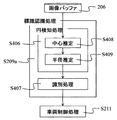
- FIG. 1 is a block diagram illustrating an overall configuration of an image processing device in a vehicle-mounted camera system according to an embodiment of the present invention.
- FIG. 3 is a diagram showing a processing flow of a stereo camera which is one embodiment of the present invention.
- FIG. 4 is a diagram showing a timing chart of a process in the stereo camera device.
- FIG. 7 is a diagram showing a part of an image stored in an image buffer step after an image processing step.
- FIG. 4B is a diagram illustrating a processing result obtained by performing image processing on the image illustrated in FIG. 4A for use in the sign recognition step.
- FIG. 5B is a diagram illustrating a histogram obtained based on a change in shading of the image illustrated in FIG. 4B.
- FIG. 6B is a diagram showing the vicinity of a radius candidate in the histogram shown in FIG. 6A.
- FIG. 11 is a diagram illustrating a histogram created from a part of a tree determined to be a circle in the circle detection process in spite of not being a sign.
- FIG. 6C is a diagram showing the vicinity of a radius candidate in the histogram shown in FIG. 6C.
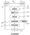
- FIG. 1 is a block diagram showing the overall configuration of an image processing device in a vehicle-mounted camera system according to one embodiment of the present invention.
- the on-vehicle stereo camera device 100 is a device mounted on a vehicle and recognizing an environment outside the vehicle based on image information of a shooting target area in front of the vehicle.
- the on-vehicle stereo camera device 100 recognizes, for example, white lines on roads, pedestrians, vehicles, other three-dimensional objects, signals, signs, lighting lamps, and the like, and brakes a vehicle (own vehicle) on which the on-vehicle stereo camera device 100 is mounted. Make adjustments such as steering adjustment.
- the in-vehicle stereo camera device 100 controls the imaging operations of the left camera 101 and the right camera 102, which are two cameras arranged on the left and right for acquiring image information, and the imaging operation of the left camera 101 and the right camera 102, and And an image input interface 103 for capturing.
- the image captured through the image input interface 103 is transmitted through a bus 109, processed by an image processing unit 104 and an arithmetic processing unit 105, and stored in the storage unit 106. Is stored in
- the image processing unit 104 compares the first image obtained from the image sensor of the left camera 101 with the second image obtained from the image sensor of the right camera 102, and compares each image with an image sensor. An image correction process such as correction of device-specific deviation due to noise or noise interpolation is performed, and this is stored in the storage unit 106. Further, the image processing unit 104 calculates a mutually corresponding portion between the first and second images, calculates disparity information, and stores the same in the storage unit 106 as described above.
- the arithmetic processing unit 105 uses the image and the parallax information (distance information for each point on the image) stored in the storage unit 106 to recognize various objects necessary for perceiving the environment around the host vehicle.
- the various objects include a person, a car, other obstacles, a traffic light, a sign, a tail lamp of a car, a head ride, and the like. Some of these recognition results and intermediate calculation results are recorded in the storage unit 106 as described above. After performing various object recognition on the captured image, the arithmetic control 105 calculates the control of the vehicle using the recognition results.
- control processing unit 108 monitors whether or not each processing unit has performed an abnormal operation and whether or not an error has occurred during data transfer. ing.
- the image processing unit 104 includes a control processing unit 108, a storage unit 106, an arithmetic processing unit 105, an image input interface 103 between the left camera 101 and the right camera 102 via the internal bus 109, It is connected to an input / output unit 107 with the network 110.
- the image processing unit 104, the storage unit 106, the arithmetic processing unit 105, the output unit 107, and the control processing unit 108 are configured by a single or a plurality of computer units.
- the storage unit 106 includes, for example, a memory that stores image information obtained by the image processing unit 104, image information created by scanning by the arithmetic processing unit 105, and the like.
- the input / output unit 107 with the external vehicle-mounted network outputs the information output from the vehicle-mounted stereo camera device 100 to the control system of the own vehicle via the vehicle-mounted network CAN110.
- FIG. 2 is a diagram showing a processing flow of the stereo camera 100 according to one embodiment of the present invention.
- an image is captured by the left and right cameras 101 and 102 in the in-vehicle stereo camera device 100, and the image data 203 and 204 captured by each of the left and right cameras 101 and 102 absorb the peculiar habit of the image sensor.
- Image processing such as correction for correction is performed.
- the processing result of the image processing step S205 is stored in the storage unit 106 in the image buffer step S206.
- the image buffer is provided in the storage unit 106 shown in FIG. Further, the two images corrected by the image processing unit 104 (corrected images of the images from the cameras 101 and 102) are used to compare the images, and thereby the parallax between the images obtained by the left and right cameras 101 and 102 is obtained. Information is obtained (parallax processing step S207).
- the image processing step S205, the image buffer step S206, and the parallax processing step S207 are performed by the image processing unit 104 illustrated in FIG. 1, and the finally obtained image and the parallax information are stored in the storage unit 106.
- step S209 various object recognition processes (step S209) are performed using the stored image and the parallax information.
- the object to be recognized includes a person, a car, other three-dimensional objects, a sign, a traffic light, a tail lamp, and the like.
- a recognition dictionary use step S210 (stored in the storage unit 106) is performed as necessary. Use.
- the recognition dictionary is stored in the storage unit 106.
- a warning is issued to the occupant by the vehicle control processing step S211 to control the braking and steering angle of the own vehicle. Is determined, or a policy for performing the avoidance control of the object is determined, and the result is output through the CAN interface 107 (CAN @ IF step S212).
- the various object recognition processing 209, the recognition dictionary use step S210, and the vehicle control processing step S211 are performed by the arithmetic processing unit 105 shown in FIG. 1, and the output to the in-vehicle network CAN 110 is performed by the CAN interface 107.
- Each of these processes and each means is configured by, for example, a single or a plurality of computer units, and is configured to be able to exchange data mutually.
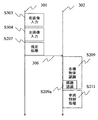
- FIG. 3 is a diagram showing a timing chart of processing in the stereo camera device.
- processing flow of two systems is shown as a processing flow 301 and a processing flow 302.
- the processing flow 301 is the processing timing in the image processing unit 104 shown in FIG. 1, and the processing flow 302 is the processing timing in the arithmetic processing unit 105 shown in FIG.
- a right image input step S303 is performed in the processing flow 301. This corresponds to the processing of capturing an image by the right camera 102 in FIG. 2, passing through the image processing 205 and storing the right image in the image buffer step S206.
- a left image input step S304 is performed. This corresponds to the processing from capturing an image by the left camera 101 in FIG. 2, through the image processing step S205, and storing the left image in the image buffer step S206.
- the parallax processing step S207 is performed. This is because, in FIG. 2, in the image buffer processing step S206, the two images from the left and right cameras 101 and 102 are read, the disparity is calculated by comparing the two images, and the calculated disparity is obtained. This corresponds to processing until information is stored in the storage unit 106. At this point, the image and the parallax information are stored in the storage unit 106. In the processing flow 301, input processing to the image buffer step S206 is performed following the parallax processing step S207.
- the processing information 306 up to the parallax processing step S207 of the processing flow 301 moves to the processing flow 302, and various object recognition 209 is performed.
- the various object recognition step S209 includes a later-described sign recognition step S209a.
- FIG. 4A, 4B, 4C, and 4D are schematic explanatory diagrams of a marker recognition function for performing marker recognition on an image stored in the image buffer 206
- FIG. 4D is an overall schematic diagram of the marker recognition processing in the marker recognition step S209a. Shows the flow.
- the sign recognition step S209a shown in FIG. 3 includes a circle detection processing step S406 and an identification processing step S407.
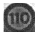
- FIG. 4A is a view showing a part of the image stored in the image buffer step S206 after the image processing step S205.
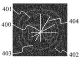
- FIG. 4B is a diagram illustrating a processing result obtained by performing image processing on the image illustrated in FIG. 4A for use in the sign recognition step S209a, and is an image having luminance in a portion where the density change is large in the vicinity of the image.
- FIG. 4C is a diagram showing a histogram obtained based on the change in shading of the image shown in FIG. 4B.
- a circle and a circle detection processing step S406 for estimating a circle and the center of the circle are performed from the image shown in FIG. 4B (images captured by the cameras 101 and 102).
- the center of the circle is obtained by “center calculation”.
- the circle detection processing step S406 is divided into center estimation (step S408) and radius estimation (step S409). Details of the radius estimation step S409 will be described later with reference to FIG.
- step S408 the center is estimated.
- a line segment 404 extending in the normal direction is drawn from each edge of the image shown in FIG. 4B, and a point where the intersections of the plurality of line segments 404 overlap by a certain number or more is estimated as the center.
- 400 is estimated as the center.
- step S409 the radius of the circle 401 (first edge) is estimated based on the histogram described in FIG. 4C. Then, identification processing of the sign detected in the identification processing step S407 (identification (recognition) of the contents of the sign) is performed, and vehicle control processing step S211 is executed.
- the horizontal axis indicates the radius from the center 400 shown in FIG. 4B, and the vertical axis indicates the number of edges within a predetermined width (within the radial width). A method of obtaining the histogram of FIG. 4C will be described.
- the number of edges 405 of the histogram shown in FIG. 4C increases, and in a case where there is no circle as in 403 shown in FIG.
- the number of edges 406 decreases.
- a histogram exceeding the predetermined edge number threshold value 407 is selected as a radius candidate.
- the counting of the number of edges may be omitted from the center 400 to a predetermined radius.
- a calculation omission area may be set.
- the calculation load on the sign recognition unit 209a can be reduced. That is, in a circle having a radius smaller than the predetermined width, it is possible to configure so as not to recognize the sign based on the change in shading.
- the calculation omission area may be reduced.
- FIG. 5 is a diagram showing a more detailed processing flow of the present invention, and shows details of the radius estimation step S409 of the flow shown in FIG. 4D.
- the separation of the random pattern is performed in the radius estimation step S409.
- the histogram creation step S500 the histogram shown in FIG. 4C is created (creation of a histogram including the number of edges and the radius that is the distance from the center of the circle to the edge).
- radius candidates are determined from the histogram created in step S500 by using a predetermined edge number threshold value 407.
- the gradient of the histogram is calculated in the histogram gradient calculation step S502 from the obtained radius candidates and the values of the histogram in the vicinity thereof.
- the random pattern separation step S503 a random pattern is separated by comparing the gradient obtained in the histogram gradient calculation step S502 with a predetermined gradient threshold.
- step S407 identification processing of the detected sign (identification (recognition) of the sign) is performed.
- FIGS. 6A, 6B, 6C, and 6D are diagrams for explaining that a label pattern and a random pattern are separated by a gradient of a histogram.
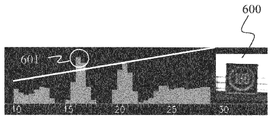
- FIG. 6A is a diagram showing a histogram created from an image of the sign 600.
- FIG. 6A the radius candidate estimated for the marker 600 is 601.
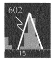
- FIG. 6B is a diagram showing the vicinity of the radius candidate 601 in the histogram shown in FIG. 6A.
- the gradient 602 of the radius candidate 601 is calculated in the histogram gradient calculation step S502.
- the gradient there are slopes on both sides of the vertex of the radius candidate 601. The slope of the slope on both sides is calculated, and the larger slope is set as the slope 602 of the radius candidate 601.
- the gradient 602 shown in FIG. 6B is equal to or greater than the gradient threshold, it is identified as a histogram indicating a sign. Since the example illustrated in FIG. 6B is a histogram indicating a marker, the gradient 602 is equal to or greater than the gradient threshold, and is identified as a histogram indicating a marker (step S503).
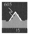
- FIG. 6C is a diagram showing a histogram created from a part 603 of a tree determined to be a circle in the circle detection processing step S406 although it is not a sign.
- the radius candidate estimated for the tree branch 603 is 604.
- FIG. 6D is a diagram showing the vicinity of the radius candidate 604 in the histogram shown in FIG. 6C.
- the gradient 605 of the radius candidate 604 is calculated in the histogram gradient calculation step S502.
- the gradient 605 is less than the gradient threshold, is identified as a random pattern, and is separated from the marker (step S503).
- the marker 600 and the random pattern 603 such as a tree branch can be separated.
- a circle detection process is performed on an image captured by the camera (101, 102), a histogram is created, and the number of edges within a predetermined width exceeds a predetermined edge threshold.
- the gradient is calculated as a radius candidate, and the gradient of the histogram is calculated from the radius candidate and the values of the histograms in the vicinity thereof.
- a random pattern such as a tree branch is excluded, a false determination of the random pattern as a sign is suppressed, and a sign recognition method and a sign recognition device of a camera device capable of improving sign recognition accuracy are provided. Can be realized.
- the center of the circular portion (circle) is estimated, and the radius estimation processing step S409 is performed.
- an angle image or intensity within a predetermined width is determined based on a position radially separated from the estimated center.
- create a histogram formed from the radius and the number of edges calculate the gradient of the histogram, perform the identification process for the calculated gradient is more than a predetermined gradient threshold, It can also be configured to recognize the sign.
- a histogram candidate exceeding a predetermined edge number threshold is determined as a radius candidate, a gradient of the histogram is calculated from the radius candidate and values of the histogram in the vicinity thereof, and the calculated gradient is compared with the gradient threshold to separate the random pattern. It can also be configured to do so.
- the histogram formed from the radius and the number of edges is created based on the change in the density of both the angle image and the intensity image.
- the above-described example is an example in which the sign recognition method and apparatus of the camera device of the present invention are mounted on a vehicle.
- the present invention is not limited to a vehicle, but is applied to other moving objects and robots. be able to.
Landscapes
- Engineering & Computer Science (AREA)
- Computer Vision & Pattern Recognition (AREA)
- Physics & Mathematics (AREA)
- General Physics & Mathematics (AREA)
- Theoretical Computer Science (AREA)
- Image Analysis (AREA)
- Traffic Control Systems (AREA)
Abstract
木の枝などのランダムパターンを除外し、ランダムパターンを標識と誤判定することを抑制し、標識認定精度を向上可能な標識認識方法を実現する。 ステップS408にて中心の推定を行う。ヒストグラム作成ステップS500によりヒストグラムを作成し、所定閾値407により半径候補を求める。求めた半径候補とその近傍のヒストグラムの値からヒストグラムの勾配をヒストグラム勾配計算ステップS502により計算する。ランダムパターン分離ステップS503にてステップS502で求めた勾配を所定閾値と比較しランダムパターンの分離を行う。標識を示すヒストグラムとランダムパターンを示すヒストグラムとは勾配が異なることからヒストグラムの勾配を閾値により判別することで標識とランダムパターンとを分離する。
Description
本発明は、カメラ装置における標識認識方法及び標識認識装置に関する。
近年、車両にカメラ装置が搭載され、車載カメラ装置として普及している。車載カメラ装置の普及により、安全運転や自動運転に向けた各種認識機能への要求が高まってきている。なかでも、ステレオカメラ装置は、画像による視覚的な情報と、対象物への距離情報を同時に計測するため、自動車周辺の様々な対象物(人、車、立体物、路面、路面標識、看板標識など)を詳細に把握でき、運転支援時の安全性の向上にも寄与するとされている。
国内外でステレオカメラ装置における標識認識機能の要求が高まり、認識精度の向上が求められている。
ステレオカメラ装置の精度劣化要因のひとつとして、木の枝などのエッジが多く現れるランダムパターンを誤って円と検知し、識別においても標識と誤認識するという課題がある。
従来から、車両に搭載され、車両の前方の状況を認識する車載カメラ装置に関する様々な技術・装置が提案されてきた。例えば、標識認識の性能向上に関しては、認識の高精度化を図るという点に着目した技術として、特許文献1がある。
特許文献1に記載の標識認識技術は、撮像した対象の円の中心推定処理、半径推定処理、及び識別処理を順に実行していく。そして、中心推定処理においては、エッジから法線方向に所定の長さ分投票を行い、一定数投票数が集まった画素を推定中心としている。
しかしながら、特許文献1に記載の技術では、精度劣化要因のひとつとして、木の枝などのエッジが多く現れるランダムパターンを誤って円と検知し、識別においても標識と誤認識する可能性があった。
つまり、対象が円形であれば、円周上のエッジから法線方向に所定の長さ分の投票が中心に集まるが、木の枝の多数の集合のように、エッジが密集しているパターンでも、投票が一定数を超える場合がある。このような場合に、上述した半径推定処理、識別処理においても誤った判定を行い、木の枝の多数の集合を標識として誤認識する可能性があった。
本発明の目的は、上記の点に鑑みてなされたものであり、円の検知処理において、木の枝などのランダムパターンを除外し、ランダムパターンを標識と誤判定することを抑制し、標識認定精度を向上可能なカメラ装置の標識認識方法及び標識認識装置を実現することである。
上記目的を達成するために、本発明は次のように構成される。
カメラ装置の標識認識方法において、カメラ装置が撮像した画像から、円形と、この円形の中心とを推定し、前記中心から前記円形の半径方向の所定の幅内におけるエッジ数と前記中心からエッジまでの距離である半径とを角度画像若しくは強度画像又は角度画像及び強度画像の濃淡変化に基づいて検出し、エッジ数と前記半径とからなるヒストグラムを作成し、前記ヒストグラムの勾配を計算し、前記計算した勾配が所定勾配閾値以上のヒストグラムについて識別処理を行い、標識を認識する。
また、標識認識装置において、カメラ装置が撮像した画像を入力する画像入力部と、前記画像入力部が入力した画像の補正処理を行う画像処理部と、前記画像処理部により補正処理された画像が標識か否かを判断し、判断した標識を識別する演算処理部とを備え、前記演算処理部は、前記補正処理された画像から、円形と、この円形の中心とを推定し、前記中心から前記円形の半径方向の所定の幅内におけるエッジ数と前記中心からエッジまでの距離である半径とを角度画像若しくは強度画像又は角度画像及び強度画像の濃淡変化に基づいて検出し、エッジ数と前記半径とからなるヒストグラムを作成し、前記ヒストグラムの勾配を計算し、前記計算した勾配が所定勾配閾値以上のヒストグラムについて識別処理を行い、標識を認識する。
本発明によれば、木の枝などのランダムパターンを除外し、ランダムパターンを標識と誤判定することを抑制し、標識認定精度を向上可能なカメラ装置の標識認識方法及び標識認識装置を実現することができる。
本発明の実施形態について添付図を参照して以下に説明する。
図1は、本発明の一実施例に係る車載カメラシステムにおける画像処理装置の全体構成を示すブロック図である。
図1において、一実施例による車載ステレオカメラ装置100は、車両に搭載され、車両前方の撮影対象領域の画像情報に基づいて車外環境を認識する装置である。
車載ステレオカメラ装置100は、例えば、道路の白線、歩行者、車両、その他の立体物、信号、標識、点灯ランプなどの認識を行い、車載ステレオカメラ装置100を搭載した車両(自車両)のブレーキ、ステアリング調整などの調整を行う。
車載ステレオカメラ装置100は、画像情報を取得する左右に配置された2つのカメラである左カメラ101及び右カメラ102と、左カメラ101及び右カメラ102の撮像動作を制御して、撮像した画像を取り込むための画像入力インタフェース103とを備える。この画像入力インタフェース103を通して取り込まれた画像は、バス109を通してデータが送られ、画像処理部104や、演算処理部105で処理され、処理途中の結果や最終結果となる画像データなどが記憶部106に記憶される。
画像処理部104は、左カメラ101の撮像素子から得られる第1の画像と、右カメラ102の撮像素子から得られる第2の画像とを比較して、それぞれの画像に対して、撮像素子に起因するデバイス固有の偏差の補正や、ノイズ補間などの画像補正処理を行い、これを記憶部106に記憶する。更に、画像処理部104は、上記第1および第2の画像の間で、相互に対応する箇所を計算して、視差情報を計算し、上述と同様に、これを記憶部106に記憶する。
演算処理部105は、記憶部106に蓄えられた画像および視差情報(画像上の各点に対する距離情報)を使い、自車両周辺の環境を知覚するために必要な、各種物体の認識を行う。各種物体とは、人、車、その他の障害物、信号機、標識、車のテールランプやヘッドライド、などである。これら認識結果や中間的な計算結果の一部が、上述と同様に記憶部106に記録される。演算制御105は、撮像した画像に対して各種物体認識を行った後に、これら認識結果を用いて車両の制御を計算する。
計算の結果として得られた車両の制御方針や、物体認識結果の一部はCANインタフェース107を通して、車載ネットワークCAN110に伝えられ、これにより車両の制動が行われる。
また、これらの動作について、各処理部が異常動作を起こしていないか、データ転送時にエラーが発生していないかどうかなどを、制御処理部108が監視しており、異常動作を防ぐ仕掛けとなっている。
上記の画像処理部104は、内部バス109を介して制御処理部108、記憶部106、演算処理部105、左カメラ101及び右カメラ102の撮像素子との間の画像入力インタフェース103と、外部車載ネットワーク110との入出力部107に接続されている。
画像処理部104、記憶部106、演算処理部105、出力部107および制御処理部108は、単一または複数のコンピュータユニットにより構成されている。
記憶部106は、例えば画像処理部104によって得られた画像情報や、演算処理部105によって、走査された結果作られた画像情報等を記憶するメモリ等により構成されている。
外部車載ネットワークとの入出力部107は、車載ステレオカメラ装置100から出力された情報を、車載ネットワークCAN110を介して自車両の制御システムに出力する。
図2は、本発明の一実施例であるステレオカメラ100の処理フローを示す図である。
まず、車載ステレオカメラ装置100における左右のカメラ101と102により画像が撮像され、左右のカメラ101と102の各々で撮像した画像データ203、204のそれぞれについて、撮像素子が持つ固有の癖を吸収するための補正などの画像処理(ステップS205)を行う。
画像処理ステップS205の処理結果は、画像バッファステップS206により記憶部106に蓄えられる。画像バッファは、図1に示した記憶部106に設けられる。更に、画像処理部104により、補正された2つの画像(カメラ101、102からの画像の補正画像)を使って、画像同士の照合を行い、これにより左右カメラ101、102で得た画像の視差情報を得る(視差処理ステップS207)。
左右画像の視差により、対象物体上のある着目点が、左右カメラ101、102の画像上の何処と何処に対応するかが明らかとなり、三角測量の原理によって、対象物までの距離が得られることになる。これを行うのが視差処理ステップS207である。画像処理ステップS205、画像バッファステップS206および視差処理ステップS207は、図1に示した画像処理部104で行われ、最終的に得られた画像、および視差情報は記憶部106に蓄えられる。
更に、上記の記憶された画像、および視差情報を用いて、各種物体認識処理(ステップS209)を行う。認識対象の物体としては、人、車、その他の立体物、標識、信号機、テールランプなどがあるが、認識の際は必要に応じて認識辞書利用ステップS210(記憶部106に記憶されている)を利用する。認識辞書は記憶部106に記憶されている。
更に、物体認識の結果と、自車両の状態(速度、舵角など)とを勘案して、車両制御処理ステップS211によって、例えば、乗員に警告を発し、自車両のブレーキングや舵角調整などの制動を行う、あるいは、それによって対象物の回避制御を行う方針を決め、その結果を、CANインタフェース107を通して出力する(CAN IFステップS212)。
各種物体認識処理209、認識辞書利用ステップS210および車両制御処理ステップS211は、図1に示した演算処理部105で行われ、車載ネットワークCAN110への出力は、CANインタフェース107にて行われる。これらの各処理及び各手段は、例えば単一または複数のコンピュータユニットにより構成され、相互にデータを交換可能に構成されている。
図3は、ステレオカメラ装置内の処理のタイミングチャートを示す図である。
図3のタイミングチャートにおいては、大きく2系統の処理の流れを、処理流れ301と、処理流れ302として示している。
処理流れ301が、図1に示した画像処理部104における処理タイミングであり、処理流れ302が、図1に示した演算処理部105における処理タイミングを示している。
図3において、まず、処理流れ301で右画像入力ステップS303が行われる。これは、図2における右カメラ102による画像撮像を行い、その後で画像処理205を経て、画像バッファステップS206により、右画像を蓄えるまでの処理に相当する。
次に、左画像入力ステップS304が行われる。これは、図2における左カメラ101による画像撮像を行い、画像処理ステップS205を経て、画像バッファステップS206に左画像を蓄えるまでの処理に該当する。
次に、視差処理ステップS207を行う。これは、図2において、画像バッファ処理ステップS206にて、左右のカメラ101、102からの2つの画像を読み出し、両画像間の照合を取ることで視差を計算し、計算して得られた視差情報を記憶部106に蓄えるまでの処理に相当する。この時点で、画像と視差情報が記憶部106に揃ったことになる。処理流れ301では、視差処理ステップS207に続いて画像バッファステップS206への入力処理が行われる。
処理流れ301の視差処理ステップS207までの処理情報306が処理流れ302に移動し、各種物体認識209が行われる。各種物体認識ステップS209は、後述する標識認識ステップS209aを有している。
各種物体認識ステップS209にて認識処理を行って、車両制御処理S211を行い、その結果を車載ネットワークCAN110に出力する運びとなる。
図4A、図4B、図4C、図4Dは、画像バッファ206に格納された画像について標識認識を行う標識認識機能の概略説明図であり、図4Dが標識認識ステップS209aによる標識認識処理の全体概略フローを示す。
図3に示した標識認識ステップS209aは、円検知処理ステップS406と識別処理ステップS407とを備える。
図4Aは、画像処理ステップS205を経て、画像バッファステップS206にて蓄えられた画像の一部を示す図である。図4Bは、標識認識ステップS209aで使用するために図4Aに示した画像を画像処理した処理結果を示す図であり、画像内における近傍での濃淡変化が大きい部分に輝度を持つ画像である。
また、図4Cは、図4Bに示した画像の濃淡変化に基づいて求められるヒストグラムを示す図である。
標識認識ステップS209aは、まず、図4Bに示した画像(カメラ101、102が撮像した画像)から、円形と、円形の中心を推定する円検知処理ステップS406(図4Dに示す)を行う。円検知処理ステップS406では、「中心演算」により円の中心を求める。円検知処理ステップS406は、中心推定(ステップS408)と半径推定(ステップS409)に分けられる。半径推定ステップS409の詳細については、図5を参照して後述する。
はじめに、ステップS408において、中心の推定を行う。図4Bに示す画像の各エッジから法線方向に延びる線分404を引き、複数の線分404の互いの交点が一定数以上重なる点を中心と推定する。図4Bでは、400が中心と推定される。次に、ステップS409において、図4Cに記載されたヒストグラムに基づいて円401(第1エッジ)の半径を推定する。そして、識別処理ステップS407にて検知した標識の識識別処理(標識の内容の識別(認識))が行われ、車両制御処理ステップS211が実行される。
図4Cのヒストグラムは、横軸が図4Bに示した中心400からの半径を示し、縦軸が所定幅内(半径方向の幅内)のエッジ数を表す。図4Cのヒストグラムの求め方を説明する。
図4Bの中心400から半径が徐々に大きくなる円を想定する。この円とエッジ(例えば、第1エッジ401や第2エッジ402)が重なった場合に、その重なったエッジ数をカウントして、図4Cの縦軸とする。
第1エッジ401のように円が存在する場合は、図4Cに示したヒストグラムのエッジ数405が多くなり、図4Bに示した403のように円が存在しない部分の場合は図4Cのヒストグラムのエッジ数406は少なくなる。図4Cに示したヒストグラムで所定エッジ数閾値407を超えたものを半径候補として選択する。
なお、中心400から所定半径まではエッジ数のカウントを省略してもよい。
標識は一般的に、直径30cm以上であることや、非常に遠くにある標識を検知しても識別処理ステップS407で処理できない場合を鑑みて、演算省略領域を設定してもよい。演算省略領域を設定することにより、標識認識部209aの演算負荷を低減することができる。つまり、所定幅内よりも小さい半径を有する円形においては、濃淡変化に基づいた標識の認識は行わないように構成することも可能である。
なお、標識認識部209aの処理能力の向上により、非常に遠くにある標識を認識して安全性向上させるために、演算省略領域を小さくしてもよい。
図5は、本発明のより詳細な処理フローを示す図であり、図4Dに示したフローの半径推定ステップS409の詳細を示している。図5に示した円検知処理(ステップS406)、識別処理(ステップS407)は演算処理部105により実行される。
図5において、ランダムパターンの分離は半径推定ステップS409内で行う。まず、ヒストグラム作成ステップS500により、図4Cに示したヒストグラムを作成する(エッジ数と円の中心からエッジまでの距離である半径とからなるヒストグラムの作成)。
次に、ステップS500にて作成したヒストグラムから、所定エッジ数閾値407により半径候補を求める。求めた半径候補とその近傍のヒストグラムの値からヒストグラムの勾配をヒストグラム勾配計算ステップS502により計算する。ランダムパターン分離ステップS503において、ヒストグラム勾配計算ステップS502で求めた勾配を所定勾配閾値と比較することで、ランダムパターンの分離を行う。
これは、標識を示すヒストグラムと、複数の木の枝のようなランダムパターンを示すヒストグラムとは、ヒストグラムの勾配が異なることから、ヒストグラムの勾配を閾値により判別することで、標識とランダムパターンとを分離可能であるという原理に基づくものである。
そして、ステップS407において、検知した標識の識別処理(標識の内容識別(認識))を行う。
図6A、図6B、図6C及び図6Dは、ヒストグラムの勾配により、標識パターンとランダムパターンとが分離する説明する図である。
図6Aは、標識600を撮像した画像から作成したヒストグラムを示す図である。図6Aにおいて、標識600で推定される半径候補は601である。図6Bは、図6Aに示したヒストグラム内の半径候補601の近傍を示す図である。
半径候補601の勾配602は、ヒストグラム勾配計算ステップS502で計算される。勾配の計算においては、半径候補601の頂点の両側に傾斜が存在するが、両側の傾斜の勾配を計算し、大の方の勾配を半径候補601の勾配602とする。
図6Bに示した勾配602が勾配閾値より以上であれば、標識を示すヒストグラムであると識別する。図6Bに示した例は、標識を示すヒストグラムであるので、勾配602は勾配閾値以上であり、標識を示すヒストグラムであると識別する(ステップS503)。
図6Cは、標識で無いにも関わらず円検知処理ステップS406で円と判定された木の一部603より作成したヒストグラムを示す図である。図6Cにおいて、木の枝603で推定される半径候補は604である。図6Dは、図6Cに示したヒストグラム内の半径候補604の近傍を示す図である。
半径候補604の勾配605は、ヒストグラム勾配計算ステップS502で計算される。
図6Dに示した例は、木の枝を示すヒストグラムであるので、勾配605は勾配閾値未満であり、ランダムパターンであると識別し、標識から分離する(ステップS503)。
標識であるか木の枝のようなランダムパターンであるかを識別する勾配閾値は、カメラの性能等により任意に設定可能であるが、一例としては、120/3=40を勾配閾値として挙げることができる。
ヒストグラムの勾配を所定勾配閾値と比較することで、標識600と木の枝等のランダムパターン603とを分離することができる。
以上のように、本発明の一実施例によれば、カメラ(101、102)で撮像した画像について、円検知処理を行い、ヒストグラムを作成し、所定幅内のエッジ数が所定エッジ閾値を越えるものについて半径候候補とし、半径候補とその近傍のヒストグラムの値からヒストグラムの勾配を算出し、算出した勾配が閾値勾配以上のものを標識として識別する。
したがって、円の検知処理において、木の枝などのランダムパターンを除外し、ランダムパターンを標識と誤判定することを抑制し、標識認定精度を向上可能なカメラ装置の標識認識方法及び標識認識装置を実現することができる。
なお、円検知処理においては、円形部(円形)の中心を推定し、半径推定処理ステップS409を行っているが、推定した中心から半径分離れた位置を基準に所定幅内における角度画像または強度画像若しくはそれらの両方の濃淡変化に基づいて、半径とエッジ数とから形成されるヒストグラムを作成して、ヒストグラムの勾配を計算し、計算した勾配が所定勾配閾値以上のヒストグラムについて識別処理を行い、標識を認識するように構成することもできる。
また、ヒストグラムから所定エッジ数閾値を超えたものを半径候補とし、半径候補とその近傍のヒストグラムの値からヒストグラムの勾配を計算し、計算した勾配を勾配閾値と比較して、ランダンパターンの分離を行うように構成することもできる。
上述した一実施例においては、角度画像及び強度画像の両方の濃淡変化に基づいて、半径とエッジ数とから形成されるヒストグラムを作成している。
また、上述した例は、本発明のカメラ装置の標識認識方法及び装置を車両に搭載される場合の例であるが、本発明は、車両に限らず、その他の移動体やロボットにも適用することができる。
100・・・ステレオカメラ、 101・・・左カメラ、 102・・・右カメラ、 103・・・画像入力インタフェース、 104・・・画像処理部、 105・・・演算処理部、 106・・・記憶部、 107・・・CANインタフェース、 108・・・制御処理部、 109・・・内部バス、 110・・・外部車載ネットワーク
Claims (10)
- カメラ装置が撮像した画像から、円形と、この円形の中心とを推定し、
前記中心から前記円形の半径方向の所定の幅内におけるエッジ数と前記中心からエッジまでの距離である半径とを角度画像若しくは強度画像又は角度画像及び強度画像の濃淡変化に基づいて検出し、エッジ数と前記半径とからなるヒストグラムを作成し、
前記ヒストグラムの勾配を計算し、
前記計算した勾配が所定勾配閾値以上のヒストグラムについて識別処理を行い、標識を認識することを特徴とするカメラ装置の標識認識方法。 - 請求項1に記載のカメラ装置の標識認識方法において、
前記ヒストグラムから所定エッジ数閾値以上の半径を半径候補として選択し、
前記選択した半径候補とその近傍のヒストグラムの値からヒストグラムの勾配を計算することを特徴とするカメラ装置の標識認識方法。 - 請求項2に記載のカメラ装置の標識認識方法において、
複数の前記エッジから法線方向に延びる線分の互い交点が一定数以上重なる点を前記円形の中心と推定することを特徴とするカメラ装置の標識認識方法。 - 請求項3に記載のカメラ装置の標識認識方法において、
推定した前記円形が、前記所定の幅よりも小さい半径を有する円形である場合は、この円形についての標識を認識する処理は行わないことを特徴とするカメラ装置の標識認識方法。 - 請求項1、2、3及び4のうちのいずれか一項に記載のカメラ装置の標識認識方法において、
前記カメラ装置は、車両に搭載されることを特徴とするカメラ装置の標識認識方法。 - カメラ装置が撮像した画像を入力する画像入力部と、
前記画像入力部が入力した画像の補正処理を行う画像処理部と、
前記画像処理部により補正処理された画像が標識か否かを判断し、判断した標識を識別する演算処理部と、
を備え、前記演算処理部は、
前記補正処理された画像から、円形と、この円形の中心とを推定し、前記中心から前記円形の半径方向の所定の幅内におけるエッジ数と前記中心からエッジまでの距離である半径とを角度画像若しくは強度画像又は角度画像及び強度画像の濃淡変化に基づいて検出し、エッジ数と前記半径とからなるヒストグラムを作成し、前記ヒストグラムの勾配を計算し、前記計算した勾配が所定勾配閾値以上のヒストグラムについて識別処理を行い、標識を認識することを特徴とする標識認識装置。 - 請求項6に記載の標識認識装置において、
前記演算処理部は、
前記ヒストグラムから所定エッジ数閾値以上の半径を半径候補として選択し、
前記選択した半径候補とその近傍のヒストグラムの値からヒストグラムの勾配を計算することを特徴とする標識認識装置。 - 請求項7に記載の標識認識装置において、
前記演算処理部は、複数の前記エッジから法線方向に延びる線分の互いの交点が一定数以上重なる点を前記円形の中心と推定することを特徴とする標識認識装置。 - 請求項8に記載の標識認識装置において、
前記演算処理部は、推定した前記円形が、前記所定の幅よりも小さい半径を有する円形である場合は、この円形についての標識を認識する処理は行わないことを特徴とする標識認識装置。 - 請求項6、7、8及び9のうちのいずれか一項に記載の標識認識装置において、
前記カメラ装置は、車両に搭載されることを特徴とする標識認識装置。
Priority Applications (3)
| Application Number | Priority Date | Filing Date | Title |
|---|---|---|---|
| JP2020528735A JP7005762B2 (ja) | 2018-07-03 | 2019-06-05 | カメラ装置の標識認識方法及び標識認識装置 |
| EP19830290.3A EP3819866A4 (en) | 2018-07-03 | 2019-06-05 | MARK DETECTION METHOD FOR A CAMERA DEVICE AND MARK DETECTION DEVICE |
| CN201980041939.3A CN112334944B (zh) | 2018-07-03 | 2019-06-05 | 摄像机装置的标志识别方法及标志识别装置 |
Applications Claiming Priority (2)
| Application Number | Priority Date | Filing Date | Title |
|---|---|---|---|
| JP2018-127092 | 2018-07-03 | ||
| JP2018127092 | 2018-07-03 |
Publications (1)
| Publication Number | Publication Date |
|---|---|
| WO2020008787A1 true WO2020008787A1 (ja) | 2020-01-09 |
Family
ID=69060930
Family Applications (1)
| Application Number | Title | Priority Date | Filing Date |
|---|---|---|---|
| PCT/JP2019/022269 WO2020008787A1 (ja) | 2018-07-03 | 2019-06-05 | カメラ装置の標識認識方法及び標識認識装置 |
Country Status (4)
| Country | Link |
|---|---|
| EP (1) | EP3819866A4 (ja) |
| JP (1) | JP7005762B2 (ja) |
| CN (1) | CN112334944B (ja) |
| WO (1) | WO2020008787A1 (ja) |
Citations (3)
| Publication number | Priority date | Publication date | Assignee | Title |
|---|---|---|---|---|
| JP2015191621A (ja) | 2014-03-28 | 2015-11-02 | 富士重工業株式会社 | 車外環境認識装置 |
| CN105203045A (zh) * | 2015-07-02 | 2015-12-30 | 天津师范大学 | 一种基于异步时域视觉传感器的产品形状完整性检测系统及检查方法 |
| JP2016103215A (ja) * | 2014-11-28 | 2016-06-02 | 本田技研工業株式会社 | 画像解析装置、画像特徴情報データベース作成方法並びに意匠類否判定装置及び方法 |
Family Cites Families (4)
| Publication number | Priority date | Publication date | Assignee | Title |
|---|---|---|---|---|
| KR20110104243A (ko) * | 2010-03-16 | 2011-09-22 | 에스케이텔레콤 주식회사 | 증강 현실에서 차폐된 마커의 인식 장치 및 방법 |
| KR101596299B1 (ko) * | 2014-01-06 | 2016-02-22 | 현대모비스 주식회사 | 교통 표지판 인식 방법 및 장치 |
| JP5961207B2 (ja) * | 2014-03-28 | 2016-08-02 | 富士重工業株式会社 | 車外環境認識装置 |
| CN107346413A (zh) * | 2017-05-16 | 2017-11-14 | 北京建筑大学 | 一种街景影像中的交通标志识别方法和系统 |
-
2019
- 2019-06-05 JP JP2020528735A patent/JP7005762B2/ja active Active
- 2019-06-05 CN CN201980041939.3A patent/CN112334944B/zh active Active
- 2019-06-05 WO PCT/JP2019/022269 patent/WO2020008787A1/ja unknown
- 2019-06-05 EP EP19830290.3A patent/EP3819866A4/en active Pending
Patent Citations (3)
| Publication number | Priority date | Publication date | Assignee | Title |
|---|---|---|---|---|
| JP2015191621A (ja) | 2014-03-28 | 2015-11-02 | 富士重工業株式会社 | 車外環境認識装置 |
| JP2016103215A (ja) * | 2014-11-28 | 2016-06-02 | 本田技研工業株式会社 | 画像解析装置、画像特徴情報データベース作成方法並びに意匠類否判定装置及び方法 |
| CN105203045A (zh) * | 2015-07-02 | 2015-12-30 | 天津师范大学 | 一种基于异步时域视觉传感器的产品形状完整性检测系统及检查方法 |
Non-Patent Citations (1)
| Title |
|---|
| INOUE, YASUO ET AL.: "Automatic Recognition of Road Signs", PROC. OF SPIE, vol. 4790, 2002, pages 543 - 550, XP055763208 * |
Also Published As
| Publication number | Publication date |
|---|---|
| EP3819866A4 (en) | 2022-04-06 |
| CN112334944A (zh) | 2021-02-05 |
| CN112334944B (zh) | 2023-09-08 |
| JP7005762B2 (ja) | 2022-02-10 |
| JPWO2020008787A1 (ja) | 2021-04-30 |
| EP3819866A1 (en) | 2021-05-12 |
Similar Documents
| Publication | Publication Date | Title |
|---|---|---|
| CN112292711B (zh) | 关联lidar数据和图像数据 | |
| CN106647776B (zh) | 车辆变道趋势的判断方法、判断装置和计算机存储介质 | |
| JP7040374B2 (ja) | 物体検出装置、車両制御システム、物体検出方法及び物体検出用コンピュータプログラム | |
| CN107667378B (zh) | 用于识别和评估路面反射的方法和装置 | |
| CN111932901B (zh) | 道路车辆跟踪检测设备、方法及存储介质 | |
| JP6457278B2 (ja) | 物体検出装置及び物体検出方法 | |
| KR20160137247A (ko) | 횡단보도 인식 결과를 이용한 안내 정보 제공 장치 및 방법 | |
| US20160217335A1 (en) | Stixel estimation and road scene segmentation using deep learning | |
| US10672141B2 (en) | Device, method, system and computer-readable medium for determining collision target object rejection | |
| US10748014B2 (en) | Processing device, object recognition apparatus, device control system, processing method, and computer-readable recording medium | |
| JP7077910B2 (ja) | 区画線検出装置及び区画線検出方法 | |
| JP6283105B2 (ja) | ステレオカメラ装置、ステレオカメラ装置を設置した車両及びプログラム | |
| EP3115933B1 (en) | Image processing device, image capturing device, mobile body control system, image processing method, and computer-readable recording medium | |
| EP3545464A1 (en) | Information processing device, imaging device, equipment control system, mobile object, information processing method, and computer-readable recording medium | |
| JP7095559B2 (ja) | 区画線検出装置及び区画線検出方法 | |
| EP4060640B1 (en) | Traffic signal recognition method and traffic signal recognition device | |
| JP6174884B2 (ja) | 車外環境認識装置および車外環境認識方法 | |
| WO2020008787A1 (ja) | カメラ装置の標識認識方法及び標識認識装置 | |
| JP6569416B2 (ja) | 画像処理装置、物体認識装置、機器制御システム、画像処理方法及び画像処理プログラム | |
| JP2018163530A (ja) | 対象物検知装置、対象物検知方法、及び対象物検知プログラム | |
| JP2018073049A (ja) | 画像認識装置、画像認識システム、及び画像認識方法 | |
| JP7064400B2 (ja) | 物体検知装置 | |
| JP2015219212A (ja) | ステレオカメラ装置及び距離算出方法 | |
| WO2018097269A1 (en) | Information processing device, imaging device, equipment control system, mobile object, information processing method, and computer-readable recording medium | |
| JP7446445B2 (ja) | 画像処理装置、画像処理方法、及び車載電子制御装置 |
Legal Events
| Date | Code | Title | Description |
|---|---|---|---|
| 121 | Ep: the epo has been informed by wipo that ep was designated in this application |
Ref document number: 19830290 Country of ref document: EP Kind code of ref document: A1 |
|
| ENP | Entry into the national phase |
Ref document number: 2020528735 Country of ref document: JP Kind code of ref document: A |
|
| NENP | Non-entry into the national phase |
Ref country code: DE |
|
| ENP | Entry into the national phase |
Ref document number: 2019830290 Country of ref document: EP Effective date: 20210203 |