WO2020008767A1 - 打込機 - Google Patents
打込機 Download PDFInfo
- Publication number
- WO2020008767A1 WO2020008767A1 PCT/JP2019/021778 JP2019021778W WO2020008767A1 WO 2020008767 A1 WO2020008767 A1 WO 2020008767A1 JP 2019021778 W JP2019021778 W JP 2019021778W WO 2020008767 A1 WO2020008767 A1 WO 2020008767A1
- Authority
- WO
- WIPO (PCT)
- Prior art keywords
- electric motor
- control unit
- driving machine
- hitting
- striking
- Prior art date
- Legal status (The legal status is an assumption and is not a legal conclusion. Google has not performed a legal analysis and makes no representation as to the accuracy of the status listed.)
- Ceased
Links
Images




Classifications
-
- B—PERFORMING OPERATIONS; TRANSPORTING
- B25—HAND TOOLS; PORTABLE POWER-DRIVEN TOOLS; MANIPULATORS
- B25C—HAND-HELD NAILING OR STAPLING TOOLS; MANUALLY OPERATED PORTABLE STAPLING TOOLS
- B25C1/00—Hand-held nailing tools; Nail feeding devices
- B25C1/06—Hand-held nailing tools; Nail feeding devices operated by electric power
Definitions
- the present invention relates to a driving machine including a hitting portion and a driving portion that operates the hitting portion.
- Patent Document 1 discloses a driving machine including a hitting unit and a driving unit that operates the hitting unit.
- the driving machine described in Patent Document 1 includes a housing, a striking unit, an electric motor as a driving unit, a reduction gear, a magazine, an injection unit mounted on the housing, a spring, a battery pack, a trigger, a contact member, a control unit, a bumper. , A rotary element, a cam, a trigger switch, and a position detection switch.
- the hitting portion has a plunger and a driver blade.
- the magazine houses a stop, and the magazine supplies the stop to the ejection section.
- the cam is provided on the rotating element.
- the spring urges the hitting portion in a direction approaching the bumper.
- the position detection switch detects the position of the hitting portion.
- the signal output from the position detection switch is input to the control unit.
- the control unit rotates the electric motor.
- the torque of the electric motor is transmitted to the speed reducer, the torque is transmitted to the cam.
- the striking section operates from the standby position.
- the cam is released from the plunger, and the hitting portion is operated by the biasing force of the spring.
- the striking section is activated, the driver blade strikes a stop at the firing section.
- the plunger collides with the bumper and the hitting part stops at the bottom dead center.
- the control unit rotates the electric motor even after the hitting unit hits the stopper.
- the cam engages the plunger the striking portion operates from the bottom dead center toward the top dead center.
- the control unit stops the electric motor when detecting that the hitting unit has reached the standby position.
- the inventor of the present application has recognized that there is room for improving the responsiveness of the operation of the hitting portion.
- An object of the present invention is to provide a driving machine capable of improving the responsiveness of the operation of a hitting portion.
- a driving machine includes a striking portion operable between a first position and a second position, and the striking portion is moved from the first position to the second position so as to strike a stopper.
- a first urging mechanism that operates in a first direction
- a second urging mechanism that operates the striking unit in a second direction from the second position toward the first position
- a striking unit that moves the striking unit to the first position.
- a stop mechanism for stopping at a standby position between the driving position and the second position, wherein the driving member applies and releases an operation force by an operator, and a stop that is hit by the hitting portion.
- a contact member capable of contacting and separating from a counterpart material into which the tool is driven, and a control unit for controlling the second urging mechanism, wherein the control unit applies an operating force to the operation member by an operator; And when the contact member comes into contact with the counterpart material, the second urging mechanism causes the hitting portion to move to the standby position. From the first control to operate in the second direction, the first process to continue the preparation control, the second to stop the preparation control and stop the hitting portion between the first position and the second position 2 processing and control for selecting either the first processing or the second processing in accordance with the elapsed time of the state in which the contact member is in contact with the counterpart material.
- the driving machine can improve the responsiveness of the operation of the hitting portion.
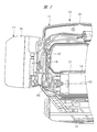
- FIG. 2 is a side cross-sectional view showing an internal structure of a driving machine, which is different from the internal structure shown in FIG. 1.
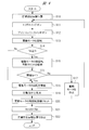
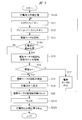
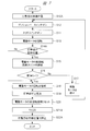
- It is a block diagram which shows the control system of a driving machine. It is a flowchart which shows the control example 1 at the time of using a driving machine in the 1st mode. It is a flowchart which shows the example 2 of a control at the time of using a driving machine in a 1st mode. It is a flowchart which shows the control example 1 at the time of using a driving machine in 2nd mode.
- the housing 11 includes a housing 11, a hitting unit 12, a magazine 13, an electric motor 14, a power transmission unit 15, a control board 16, a battery pack 17, and a counter weight 18.
- the housing 11 is made of metal and synthetic resin.
- the housing 11 includes a cylindrical main body 19, a handle 20 connected to the main body 19, and a motor case 21 connected to the main body 19. Have.
- the mounting part 22 is connected to the handle 20 and the motor case 21.
- the injection unit 23 is provided outside the main body 19, and the injection unit 23 is fixed to the main body 19.
- a push lever 24 is attached to the injection unit 23.
- the push lever 24 is operable in the direction of the center line A1 with respect to the ejection unit 23.
- the ejection section 23 and the push lever 24 form an ejection path 25. The operator can make the tip of the push lever 24 contact and separate from the counterpart material W1.
- the magazine 13 is supported by the housing 11 and the ejection unit 23.
- the magazine 13 houses a plurality of fasteners 26.
- the stopper 26 includes a nail, and the material of the stopper 26 includes metal, non-ferrous metal, and steel.
- the stops 26 are connected to each other by connecting elements.
- the connection element may be a wire, an adhesive, or a resin.
- the stopper 26 has a rod shape.
- the magazine 13 has a feeder. The feeder sends the stopper 26 housed in the magazine 13 to the ejection path 25.
- the injection path 25 determines the driving position of the stopper 26, the posture of the stopper 26, and the driving direction of the stopper 26.
- the hitting portion 12 is provided over the inside and outside of the main body portion 19.
- the striking section 12 has a metal plunger 27 and a metal driver blade 28.
- the plunger 27 is arranged in the main body 19.
- the driver blade 28 is fixed to the plunger 27.
- a plunger shaft 29 is provided in the main body 19.
- a top holder 30 and a bottom holder 31 are fixedly provided in the housing 11.
- the plunger shaft 29 is supported by the top holder 30 and the bottom holder 31.
- the hitting portion 12 is supported by the housing 11 via the plunger shaft 29, the top holder 30, and the bottom holder 31 so as to be capable of reciprocating operation.
- the plunger 27 is attached to a plunger shaft 29, and the plunger 27 is operable along a center line A1 of the plunger shaft 29.
- the driver blade 28 is operable in parallel with the center line A1 together with the plunger 27, and operates within the main body 19 and the injection path 25. The operation direction of the driver blade 28 is guided by the ejection unit 23 and the push lever 24.
- the counter weight 18 suppresses the reaction received by the housing 11.
- the material of the counterweight 18 may be any of metal, non-ferrous metal, steel, and ceramic.
- the counter weight 18 has a cylindrical shape and is attached to a plunger shaft 29.
- the counterweight 18 is operable with respect to the plunger shaft 29 along a center line A1.
- the plunger shaft 29 regulates the operation direction of the counterweight 18 and the plunger 27.
- a spring 32 is disposed in the main body 19, and the spring 32 is disposed between the plunger 27 and the counterweight 18 in a direction along the center line A1.
- the spring 32 is a compression coil spring, and can expand and contract in a direction along the center line A1.
- the material of the spring 32 may be metal, non-ferrous metal, or ceramic.
- the spring 32 receives a compressive force in the direction of the center line A1 and stores elastic energy.
- the weight bumper 33 and the plunger bumper 34 are provided in the main body 19.
- the weight bumper 33 is disposed between the top holder 30 and the counter weight 18.
- the plunger bumper 34 is disposed between the bottom holder 31 and the plunger 27.
- the weight bumper 33 and the plunger bumper 34 are both made of synthetic rubber.
- the plunger 27 receives from the spring 32 an urging force in the first direction B1 approaching the bottom holder 31 in a direction along the center line A1.
- the counter weight 18 receives from the spring 32 a biasing force in the second direction B2 approaching the top holder 30 in a direction along the center line A1.
- the first direction B1 and the second direction B2 are opposite to each other, and the first direction B1 and the second direction B2 are parallel to the center line A1 direction.
- the driving machine 10 shown in FIG. 1 shows a usage example in which the center line A1 is parallel to a vertical line.
- the operation of the hitting portion 12, the plunger 27, or the counterweight 18 in the first direction B ⁇ b> 1 is defined as lowering.
- the operation of the hitting section 12, the plunger 27, or the counterweight 18 in the second direction B ⁇ b> 2 is defined as rising.
- the battery pack 17 is attachable to and detachable from the mounting section 22, and the battery pack 17 includes a storage case 35 and a plurality of battery cells stored in the storage case 35.
- the battery cell is a secondary battery that can be charged and discharged.
- any of a lithium ion battery, a nickel hydride battery, a lithium ion polymer battery, and a nickel cadmium battery can be used.
- the battery pack 17 is a DC power supply, and the electric power of the battery pack 17 is supplied to the electric motor 14.
- the main body side terminal is provided on the mounting portion 22, and the battery side terminal is provided on the battery pack 17. When the battery pack 17 is attached to the mounting section 22, the main body side terminal and the battery side terminal are electrically connected.
- the control board 16 is provided in the mounting section 22, and the control board 16 is provided with a control section 37 and an inverter circuit 38 shown in FIG.
- the control unit 37 is a microcomputer having an input port, an output port, a timer, and a storage unit.
- the inverter circuit 38 connects and disconnects a path for supplying the electric power of the battery pack 17 to the electric motor 14.
- Inverter circuit 38 has a switching element.
- a trigger 39 and a trigger switch 40 are provided on the handle 20.
- the trigger switch 40 is turned on when an operator applies an operating force to the trigger 39, and the trigger switch 40 is turned off when the operating force applied to the trigger 39 is released.
- a first position detection switch 64 and a second position detection switch 54 are provided in the main body 19. The first position detection switch 64 and the second position detection switch 54 detect the position of the counter weight 18 in the direction of the center line A1 and output a signal.
- the position of the counter weight 18 in the direction of the center line A1 detected by the first position detection switch 64 is different from the position of the counter weight 18 in the direction of the center line A1 detected by the second position detection switch 54.
- the first position detection switch 64 is a sensor that detects that the striking section 12 has reached the top dead center.
- the second position detection switch 54 is a sensor that detects that the striking section 12 has reached the limit position. The top dead center and the limit position of the striking section 12 will be described later.
- a push lever switch 55 is provided on the magazine 13.
- the push lever switch 55 detects whether the push lever 24 is in contact with or separated from the partner material W1, and outputs a signal.
- the electric motor 14 has a rotor and a stator, and a drive shaft 41 is connected to the rotor.
- the drive shaft 41 of the electric motor 14 rotates when electric power is supplied from the battery pack 17.
- the phase detection sensor 56 is provided in the motor case 21.
- the phase detection sensor 56 detects a phase in the rotation direction of the drive shaft 41 and outputs a signal.
- the control unit 37 processes the signal of the trigger switch 40, the signal of the first position detection switch 64, the signal of the second position detection switch 54, the signal of the push lever switch 55, the signal of the phase detection sensor 56, and the inverter circuit. 38 is controlled.
- the speed reducer 42 is arranged in the motor case 21.
- the speed reducer 42 has a planetary gear mechanism, an input element 43 and an output element 44, and the input element 43 is connected to the drive shaft 41.
- the speed of the output element 44 of the speed reducer 42 is lower than the speed of the input element 43.
- the electric motor 14 and the speed reducer 42 are arranged concentrically about the center line A2. 1, the center line A1 and the center line A2 intersect at right angles in FIG.
- the power transmission unit 15 converts the rotational force of the output element 44 into an operating force of the hitting unit 12 and converts the rotational force of the output element 44 into an operating force of the counterweight 18.
- the power transmission unit 15 includes a first gear 45, a second gear 46, a third gear 47, a plunger arm 48, and a weight arm 49.
- the first gear 45 is fixed to the output element 44.
- the second gear 46 is rotatably supported by the first support shaft 50.
- the third gear 47 is rotatably supported by the second support shaft 51.
- a gear holder 52 is fixedly provided in the housing 11, and the first support shaft 50 and the second support shaft 51 are attached to the gear holder 52.
- the center line A2, the center line A3 of the first support shaft 50, and the center line A4 of the second support shaft 51 are parallel to each other.
- the first support shaft 50 is disposed between the output element 44 and the second support shaft 51 in a direction along the center line A1.
- the second gear 46 meshes with the first gear 45 and the third gear 47.
- a plurality of cam rollers 53 are provided on the second gear 46.
- the plurality of cam rollers 53 are arranged at intervals in the rotation direction of the second gear 46.
- a plurality of cam rollers 57 are provided on the third gear 47.
- the plurality of cam rollers 57 are arranged at intervals in the rotation direction of the third gear 47.
- the plunger arm 48 is provided on the plunger 27.
- the plunger arm 48 is operable with the plunger 27 in the direction of the center line A1.
- the plunger arm 48 is made of metal, for example.
- the weight arm 49 is provided on the counter weight 18.
- the weight arm 49 is operable together with the counterweight 18 in the direction of the center line A1.
- the weight arm 49 is made of metal, for example.
- a rotation regulating mechanism 66 is provided in the motor case 21.
- the rotation restricting mechanism 66 can be engaged with and released from the drive shaft 41.
- the rotation restricting mechanism 66 prevents the drive shaft 41 from rotating reversely with the rotational force. Further, the rotation regulating mechanism 66 does not prevent the drive shaft 41 from rotating forward.
- the operator can select the first mode and the second mode when using the driving machine 10.
- the striking section 12 is operated by pressing the push lever 24 against the opponent W1 in a state where an operating force is applied to the trigger 39.
- the striking unit 12 is operated by applying an operating force to the trigger 39 while the push lever 24 is pressed against the partner material W1.
- the cam roller 53 is engaged with the plunger arm 48, and the cam roller 57 is engaged with the weight arm 49.
- the spring 32 is sandwiched between the plunger 27 and the counterweight 18 and receives a compressive load in the direction of the center line A1.
- the plunger 27 receives an urging force in the first direction B1 from the spring 32, and the counterweight 18 receives an urging force in the second direction B2 from the spring 32.
- the biasing force in the first direction B1 received by the plunger 27 is transmitted to the second gear 46 via the plunger arm 48, and the second gear 46 receives a rotational force.
- the biasing force in the second direction B2 received by the counterweight 18 is transmitted to the third gear 47 via the weight arm 49, and the third gear 47 receives a rotational force.
- the rotational force received by the third gear 47 is transmitted to the second gear 46.
- the second gear 46 receives the torque
- the torque is transmitted to the first gear 45.
- the rotation restricting mechanism 66 prevents the drive shaft 41 of the electric motor 14 from rotating in the reverse direction. For this reason, the first gear 45 is maintained in a stopped state.
- the plunger 27 is separated from the plunger bumper 34 and the counterweight 18 is separated from the weight bumper 33.
- the control unit 37 detects that the trigger switch 40 is turned on in step S11.
- the control unit 37 detects that the push lever switch 55 is turned on in step S12 while the trigger switch 40 is on, the control unit 37 causes the electric motor 14 to supply the electric power of the battery pack 17 to the electric motor 14 in step S13. Then, the drive shaft 41 of the electric motor 14 is rotated forward.
- the torque of the drive shaft 41 is amplified by the speed reducer 42 and transmitted to the output element 44, and the first gear 45 rotates.
- the torque of the first gear 45 is transmitted to the third gear 47 via the second gear 46.
- the plunger 27 operates in the second direction B2 against the urging force of the spring 32. That is, the striking portion 12 moves up. Further, the counter weight 18 operates in the first direction B1. That is, the counter weight 18 falls. As described above, when the plunger 27 is raised and the counterweight 18 is lowered, the spring 32 is further compressed, and elastic energy is stored in the spring 32.
- the control unit 37 determines whether or not the total number of rotations N of the electric motor 14 is equal to or less than a threshold value Nm in step S14.
- the total number of rotations N of the electric motor 14 is the number of rotations from the time when the electric motor 14 starts rotating.
- the control unit 37 stores the threshold value Nm in advance.
- the threshold value Nm is a value corresponding to the position where the striking portion 12 is close to the top dead center in the direction of the center line A1, that is, the position immediately before.
- the immediately preceding position is between the top dead center and the standby position in the direction of the center line A1.
- the distance from the top dead center to the position immediately before is, for example, 10 mm.
- step S14 the controller 37 continues to count the total number of rotations N of the electric motor 14 in step S15.
- step S16 the control unit 37 determines whether the elapsed time t from when the push lever switch 55 is turned on is less than the threshold value tp.
- the control unit 37 stores the threshold value tp in advance.
- the threshold value tp is a value for distinguishing a situation where the push lever switch 55 is turned on into a first situation and a second situation.
- the first situation is a situation where the operator has pressed the push lever 24 against the partner material W1.
- the second situation is a situation where the push lever 24 has come into contact with an object different from the partner material W1.
- the threshold value tp can be set to, for example, 50 ms, that is, 0.05 seconds.
- step S16 If the control unit 37 determines No in step S16, this is the second situation. Therefore, if the control unit 37 determines No in step S16, it stops the supply of electric power to the electric motor 14 in step S17, stops the electric motor 14, and proceeds to step S11. That the control unit 37 determines Yes in step S16 is the first situation. Therefore, if the determination is Yes in step S16, the control unit 37 continues the rotation of the electric motor 14 in step S18. When the control unit 37 determines No in step S14, the process proceeds to step S18.
- step S19 the control unit 37 detects that the striking unit 12 has reached the top dead center based on the signal of the first position detection switch 64. Further, the cam roller 53 is released from the plunger arm 48. The striking portion 12 is at the top dead center immediately before the cam roller 53 is released from the plunger arm portion 48.
- the plunger 27 is urged in the first direction B1 by the elastic energy of the spring 32, and the driver blade 28 hits the stopper 26. After the driver blade 28 hits the stopper 26, the plunger 27 collides with the plunger bumper 34 as shown in FIG.
- the plunger bumper 34 absorbs a part of the operating energy of the hitting portion 12 and suppresses the vibration of the housing 11.
- the counterweight 18 is urged in the second direction B2 by the elastic energy of the spring 32.
- the counterweight 18 rises at the same time as the striking unit 12 descends, and receives a reaction when the striking unit 12 strikes.
- the counter weight 18 collides with the weight bumper 33 as shown in FIG. 1, and the counter weight 18 stops at the top dead center.
- the weight bumper 33 absorbs a part of the operating energy of the counterweight 18 and suppresses the vibration of the housing 11.
- the operator separates the push lever 24 from the counterpart W1.
- the control unit 37 rotates the electric motor 14 even after the hitting unit 12 drives the stopper 26 into the counterpart material W1.
- the cam roller 53 engages with the plunger arm 48
- the striking portion 12 rises from the bottom dead center.
- the cam roller 57 engages with the weight arm 49, the counterweight 18 descends from the top dead center.
- the control section 37 When detecting that the hitting section 12 has reached the top dead center, the control section 37 once resets the total number of rotations N of the electric motor 14 in step S20, and starts counting the total number of rotations N of the electric motor 14 again. . Then, in step S21, the control unit 37 detects that the striking unit 12 has reached the standby position. In step S21, when the total number of rotations N of the electric motor 14 is equal to or greater than the threshold value Nt and less than the threshold value Nm, the control unit 37 determines that the striking unit 12 has reached the standby position. The control unit 37 stores a threshold value Nt in advance so as to correspond to the standby position of the striking unit 12. The standby position of the striking unit 12 is between the bottom dead center and the immediately preceding position in the direction of the center line A1. The threshold value Nt is, for example, a distance of 20 mm from the top dead center.
- the control unit 37 stops the electric motor 14 in step S22 to stop the striking unit 12 at the standby position, and ends the control example of FIG.
- the responsiveness of the operation of the striking unit 12 is improved. Specifically, the responsiveness from when the trigger switch 40 is turned on and the push lever switch 55 is turned on to when the striking portion 12 operates in the first direction B1 is improved.
- control unit 37 determines No in step S16, the control unit 37 stops the electric motor 14 in step S17. Therefore, when the push lever 24 comes into contact with an object different from the counterpart material W1, it is possible to prevent the striking portion 12 from operating in the first direction B1.
- control unit 37 determines No in step S14, it proceeds to step S19 via step S18 regardless of the position of the striking unit 12 in the direction of the center line A1. Therefore, the responsiveness of the operation of the striking portion 12 is improved.
- control unit 37 estimates the position of the striking unit 12 in the direction of the center line A1 from the total number of rotations N of the electric motor 14. This is because there is a correlation between the total number of rotations N of the electric motor 14 and the position of the striking portion 12 in the direction of the center line A1.
- Example 2 of control in first mode Example 2 of control in first mode
- Example 2 of control when the operator selects the first mode will be described with reference to the flowchart in FIG.
- steps having the same contents as the steps shown in FIG. 4 are denoted by the same step numbers as those in FIG.
- the control unit 37 has stopped the electric motor 14 in step S10A, and the striking unit 12 has stopped at the standby position.
- the control unit 37 performs the processing of step S11, step S12, and step S13 after step S10A.
- step S14A following step S13 the control unit 37 determines whether or not the hitting unit 12 has reached the immediately preceding position based on the signal of the second position detection switch 54.
- step S14A When the control unit 37 determines Yes in step S14A, the process proceeds to step S15. When the control unit 37 determines No in step S14A, the process proceeds to step S18.
- step S21A control unit 37 detects that striking unit 12 has reached the standby position. If the total number of rotations N of the electric motor 14 is equal to or greater than the threshold Nt in step S21A, the control unit 37 determines that the striking unit 12 has reached the standby position. When the striking unit 12 reaches the standby position, the control unit 37 stops the electric motor 14 in step S22A to stop the striking unit 12 at the standby position, and ends the control example of FIG.
- control unit 37 When the control unit 37 performs the control example 2 of the first mode, it is possible to obtain the same effect as the control example 1 of the first mode.
- Control Example 1 of Second Mode Control Example 1 in the case where the operator selects the second mode will be described with reference to the flowchart of FIG. 6, steps having the same contents as the steps shown in FIG. 4 are denoted by the same step numbers as those in FIG.
- the control unit 37 performs the process of step S12 after step S10, and then proceeds to step S13 after performing the process of step S11. Further, the control unit 37 performs the process of step S17, and proceeds to step S12.
- control unit 37 When the control unit 37 performs the control example 1 of the second mode, it is possible to obtain the same effect as the control example 1 of the first mode.
- Example 2 of control in second mode Example 1 of control in the case where the operator selects the second mode will be described with reference to the flowchart in FIG. Steps having the same contents as the steps shown in FIG. 5 among the steps shown in FIG. 7 are given the same step numbers as those in FIG.
- the control unit 37 performs the process of step S12 following step S10A, then performs the process of step S11, and proceeds to step S13. Further, the control unit 37 performs the process of step S17, and proceeds to step S12.
- control unit 37 When the control unit 37 performs the control example 2 of the second mode, it is possible to obtain the same effect as the control example 2 of the first mode.
- control unit 37 detects that the trigger switch 40 and the push lever switch 55 are on while the impact unit 12 is stopped at the standby position, the control unit 37 turns on the trigger switch 40 and the push lever switch 55.
- the electric motor 14 is rotated regardless of the execution order.
- control unit 37 When the second mode is selected, when the push lever 24 is pressed against the partner material W1 and the control unit 37 detects that the push lever switch 55 is turned on for a predetermined time or more, the control unit 37 rotates the electric motor 14. And stop. Then, the striking unit 12 rises from the standby position, moves to an arbitrary position before the top dead center, and the striking unit 12 stops. Any position can be defined as a second standby position. Thereafter, when the operating force is applied to the trigger 39 while the push lever switch 55 is on, and the control unit 37 detects that the trigger switch 40 is on, the control unit 37 rotates the electric motor 14 to cause the striking unit 12 to rotate. When activated, the striking section 12 may strike the stopper 26.
- step S11 regardless of whether the trigger switch 40 is on or off, the control unit 37 proceeds to step S12 and detects that the push lever switch 55 is on.
- step S13 the control unit 37 starts the operation after the push lever switch 55 is turned on. It is determined whether the elapsed time t is less than the threshold value tp.
- the control unit 37 is provided with a memory unit, and stores the threshold value tp in advance in this memory unit.
- the threshold value tp is a value for distinguishing a situation where the push lever switch 55 is turned on into a first situation and a second situation.
- the first situation is a situation where the operator has pressed the push lever 24 against the partner material W1.
- the second situation is a situation where the push lever 24 comes into contact with an object different from the mating material W1 or a case where the push lever 24 has accidentally hit the mating material W1 such as wood.
- the threshold value tp is, for example, about 50 ms (0.05 seconds), but can be arbitrarily determined.
- step S13 it is determined whether or not the total number of rotations N of the electric motor 14 is equal to or greater than a threshold value Nm.
- the total number of rotations N of the electric motor 14 is the number of rotations of the electric motor 14 from the time when the striking unit is moved from the bottom dead center by the electric motor 14.
- the control unit 37 stores a threshold value Nm.
- the threshold value Nm is a value corresponding to the position where the striking portion 12 is close to the top dead center in the direction of the center line A1, that is, the position immediately before.
- the immediately preceding position is between the top dead center and the standby position in the direction of the center line A1.
- the distance from the top dead center to the position immediately before is, for example, 10 mm.
- the process proceeds to step 17, and the process proceeds to step 21 without rotating the electric motor 14.
- the process proceeds to step 15, and the electric motor 14 is driven to rotate while the push lever switch is in the ON state.
- step S16 the count of the total number of rotations N of the electric motor 14 is continued to calculate the movement amount from the bottom dead center of the striking unit 12.
- step 18 If it is determined in step 18 that the push lever switch 55 is off (Yes), the process proceeds to step 12 and waits until the push lever is turned on again. If it is determined that the push lever switch 55 is on (No), the process proceeds to step 19, and the rotation of the electric motor 17 is maintained. If the value becomes equal to or larger than the threshold value Nm during the rotation of the electric motor 14 in step 20, the process proceeds to step 21 and the electric motor 17 is stopped. In step 22, when the trigger switch 40 and the push lever switch 55 are turned on for a certain period of time or more, the electric motor 14 is driven to move the striker to the top dead center. The engagement is released, and a fastener (a nail) 26 is driven with a driver blade 28.
- step S23 the total number of rotations N of the electric motor 14 is once reset, and in step S24, when the electric motor 14 starts moving the striking unit 12 from the bottom dead center toward the top dead center, the total number of rotations N is counted. To start again. Then, it is detected that the striking section 12 has reached the standby position.
- the control unit 37 stops the electric motor 14 in step S25 to stop the hitting unit 12 at the standby position, and ends the control example of FIG.
- the push lever 24 is operated to turn on (slightly push) the push lever switch 55 a plurality of times, whereby the striking unit 12 can be moved from the standby position to the immediately preceding position, and the driving operation is performed. The response at the time can be improved.
- control unit 37 If the control unit 37 does not detect the push lever switch 55 to be turned on again within a predetermined time from the time when the push lever switch 55 is turned off, the control unit 37 rotates the electric motor 14 in the reverse direction and the driver blade 28
- the hitting portion 12 may be operated in the second direction up to a position where the hitting portion 12 does not contact the head. In this case, by changing the direction of the current supplied to the electric motor 14, the electric motor 14 can be rotated forward and backward.
- the driving machine 10 is an example of a driving machine.
- the top dead center of the striking section 12 is an example of a first position of the striking section.
- the bottom dead center of the striking section 12 is an example of a second position of the striking section.
- the striking unit 12 is an example of a striking unit.
- the first direction B1 is an example of a first direction.
- the second direction B2 is an example of a second direction.
- the spring 32 is an example of a first biasing mechanism and an elastic member.
- the electric motor 14 and the power transmission unit 15 are examples of a second urging mechanism.
- the rotation control mechanism 66 is an example of a stop mechanism.
- the trigger 39 is an example of an operation member.
- the push lever 24 is an example of a contact member.
- the battery pack 17, the control unit 37, and the inverter circuit 38 are examples of a control unit.
- the process performed by the control unit 37 in step S13 is an example of the preparation control. Determining No in step S16 by the control unit 37 is an example of “the elapsed time is equal to or longer than a predetermined time”. Determining “Yes” in step S16 by the control unit 37 is an example of “the elapsed time is shorter than a predetermined time”.
- the process from step S13 to step S18 via step S16 is an example of the first process.
- the process from step S13 to step S17 via step S16 is an example of the second process.
- the elapsed time t is an example of the elapsed time.
- the threshold value tp is an example of a predetermined time. Further, judging No in step 13 of FIG. 8 is an example of “the elapsed time is equal to or longer than a predetermined time”. Determining “Yes” in step S13 by the control unit 37 is an example of “the elapsed time is less than a predetermined time”. The process from step S13 in FIG. 8 to step S19 via step S14 is an example of the first process. The process from step S13 to step S17 via step S14 is an example of the second process. The elapsed time t is an example of the elapsed time. The threshold value tp is an example of a predetermined time.
- the electric motor 14 is an example of an electric motor.
- the power transmission unit 15 is an example of a power transmission unit.
- Battery pack 17 is an example of a power supply unit.
- the state where the control unit 37 determines No in step S16 is an example of "the distance between the hitting unit and the first position is less than a predetermined value".
- the housing 11 is an example of a housing.
- the counter weight 18 is an example of a weight.
- the driving machine is not limited to the embodiment described above, and can be variously changed without departing from the gist thereof.
- the position of the striking portion in the center line direction can be determined not by the total number of rotations of the electric motor but by the total rotation angle from the time when the electric motor starts rotating.
- the position of the hitting portion in the center line direction that is, the top dead center, the immediately preceding position, and the standby position can all be performed by a single position detection sensor.
- An optical sensor, a magnetic sensor, or the like can be used as the position detection sensor.
- the position of the hitting portion in the center line direction can be directly detected without indirectly judging the position of the weight from the position of the weight.
- the driving machine does not need to include the counterweight.
- the first end of the first urging mechanism may directly or indirectly contact the plunger, and the second end of the first urging member may directly or indirectly contact the housing.
- the power supply for supplying electric power to the electric motor may be either a DC power supply or an AC power supply.
- the first biasing mechanism includes a solid spring, a gas spring, and a synthetic rubber.
- Solid springs include, for example, metal springs, non-ferrous metal springs, and composite springs of metal and non-metal. Solid springs include tension springs, spiral springs, leaf springs, and torsion springs in addition to compression springs.
- the gas spring has a pressure accumulating chamber in which an inert gas such as air, nitrogen, or a rare gas is sealed at atmospheric pressure or under a pressurized state.
- the gas spring is a mechanism using the elastic force of the inert gas.
- the housing is an element that supports the hitting portion, and includes a body, a case, a frame, and a shell.
- the stop mechanism that holds the hitting portion at the standby position may be an element that engages / disengages one of the rotating elements of the speed reducer.
- the stop mechanism for holding the hitting portion at the standby position may be an electric motor.
- the motor includes a hydraulic motor, a pneumatic motor, and an engine in addition to the electric motor.
- the power transmission unit includes, in addition to the gear transmission, a wrapping transmission, a friction transmission, and a traction device.
- the power transmission unit also has a function of a clutch that connects and disconnects a path that transmits the rotational force of the motor to the hitting unit.
- the operating member may be either a member that can be operated linearly with respect to the housing or a member that can be operated in an arc shape around the support shaft in the housing.
- the operation member may be any of a lever, a button, and an arm.
- the contact member is operably provided in the center line direction with respect to the housing.
- the contact member may be any of a lever, an arm, and a shaft.
- the fastener may be a nail with a head or a nail without a head.
- the stopper includes staples in addition to the rod-shaped nails.
- the driving machine can also be used in a state where a vertical line intersects with a center line which is a direction in which the hitting section operates.
- the material of the counterpart material may be any of concrete, wood, tile, plaster, metal, and non-ferrous metal.
Landscapes
- Engineering & Computer Science (AREA)
- Mechanical Engineering (AREA)
- Portable Nailing Machines And Staplers (AREA)
Abstract
打撃部が作動する応答性を向上させることの可能な打込機を提供する。第1位置と第2位置との間で作動可能な打撃部(12)と、打撃部(12)を第1方向(B1)で作動させるスプリング(32)と、打撃部(12)を第2方向(B2)で作動させる電動モータ(14)と、打撃部(12)を待機位置で停止させる停止機構と、を有する、打込機(10)であって、トリガ(39)と、プッシュレバー(24)と、電動モータを制御する制御部と、を有し、制御部は、電動モータ(14)により打撃部(12)を待機位置から第2方向(B2)で作動させる準備制御と、準備制御を継続させる第1処理と、準備制御を終了させて打撃部(12)を第1位置と第2位置との間で停止させる第2処理と、第1処理または第2処理の何れかを、作業者がプッシュレバー(24)を相手材(W1)に接触させた状態の経過時間に応じて選択する制御と、を行う。
Description
本発明は、打撃部と、打撃部を作動させる駆動部と、を備えた打込機に関する。
打撃部と、打撃部を作動させる駆動部と、を備えた打込機が特許文献1に記載されている。特許文献1に記載された打込機は、ハウジング、打撃部、駆動部としての電動モータ、減速機、マガジン、ハウジングに取り付けた射出部、スプリング、電池パック、トリガ、接触部材、制御部、バンパ、回転要素、カム、トリガスイッチ、位置検出スイッチを有する。打撃部は、プランジャ及びドライバブレードを有する。マガジンは止具を収容し、マガジンは止具を射出部へ供給する。カムは回転要素に設けられている。スプリングは、打撃部をバンパに近づく向きで付勢する。位置検出スイッチは、打撃部の位置を検出する。位置検出スイッチから出力される信号は、制御部に入力される。
特許文献1に記載された打込機は、トリガスイッチがオフされていると、制御部は電動モータを停止している。また、カムがプランジャに係合し、打撃部は待機位置で停止している。打撃部が待機位置に停止していると、プランジャはバンパから離間している。
作業者が接触部材を相手材に押し付け、かつ、トリガに操作力を付加してトリガスイッチがオンすると、制御部は電動モータを回転させる。電動モータの回転力が減速機に伝達されると、その回転力がカムに伝達される。このため、打撃部は待機位置から作動する。打撃部が上死点に到達すると、カムがプランジャから解放され、打撃部はスプリングの付勢力で作動する。打撃部が作動すると、ドライバブレードは、射出部にある止具を打撃する。プランジャがバンパに衝突し、打撃部は下死点で停止する。制御部は、打撃部が止具を打撃した後も電動モータを回転させる。カムがプランジャに係合すると、打撃部は下死点から上死点に向けて作動する。制御部は、打撃部が待機位置に到達したことを検出すると、電動モータを停止させる。
本願発明者は、打撃部が作動する応答性を向上させる余地がある、という課題を認識した。
本発明の目的は、打撃部が作動する応答性を向上させることの可能な打込機を提供することにある。
一実施形態の打込機は、第1位置と第2位置との間で作動可能な打撃部と、止具を打撃するように前記打撃部を前記第1位置から前記第2位置に向けて第1方向に作動させる第1付勢機構と、前記打撃部を前記第2位置から前記第1位置に向けて第2方向に作動させる第2付勢機構と、前記打撃部を前記第1位置と前記第2位置との間の待機位置で停止させる停止機構と、を有する、打込機であって、作業者が操作力を付加及び解除する操作部材と、前記打撃部により打撃される止具を打ち込む相手材に接触及び離間可能な接触部材と、前記第2付勢機構を制御する制御部と、を有し、前記制御部は、作業者が前記操作部材に操作力を付加し、かつ、前記接触部材が前記相手材に接触すると、前記第2付勢機構により前記打撃部を前記待機位置から前記第2方向に作動させる準備制御と、前記準備制御を継続させる第1処理と、前記準備制御を終了させて前記打撃部を前記第1位置と前記第2位置との間で停止させる第2処理と、前記第1処理または前記第2処理の何れかを、前記接触部材が前記相手材に接触した状態の経過時間に応じて選択する制御と、を行う。
一実施形態の打込機は、打撃部が作動する応答性を向上させることが可能である。
以下、本発明における打込機の一実施形態を図面を参照して説明する。
図1及び図2に示す打込機10は、ハウジング11、打撃部12、マガジン13、電動モータ14、動力伝達部15、制御基板16、電池パック17及びカウンタウェイト18を有する。ハウジング11は、金属及び合成樹脂で構成されており、ハウジング11は、筒形状の本体部19と、本体部19に接続されたハンドル20と、本体部19に接続されたモータケース21と、を有する。装着部22がハンドル20及びモータケース21に接続されている。
射出部23が本体部19の外に設けられ、射出部23が本体部19に固定されている。プッシュレバー24が射出部23に取り付けられている。プッシュレバー24は、射出部23に対して中心線A1方向に作動可能である。射出部23及びプッシュレバー24は、射出路25を形成している。作業者は、プッシュレバー24の先端を相手材W1に対して接触及び離間させることが可能である。
マガジン13は、ハウジング11及び射出部23により支持されている。マガジン13は、止具26を複数収容する。止具26は釘を含み、止具26の材質は、金属、非鉄金属、鋼を含む。止具26同士は接続要素で互いに接続されている。接続要素は、ワイヤ、接着剤、樹脂の何れでもよい。止具26は棒形状である。マガジン13はフィーダを有する。フィーダは、マガジン13に収容された止具26を射出路25に送る。射出路25は、止具26の打ち込み位置、止具26の姿勢、止具26の打ち込み方向を定める。
打撃部12は、本体部19の内外に亘って設けられている。打撃部12は、金属製のプランジャ27及び金属製のドライバブレード28を有する。プランジャ27は、本体部19内に配置されている。ドライバブレード28は、、プランジャ27に固定されている。プランジャシャフト29が本体部19内に設けられている。トップホルダ30及びボトムホルダ31が、ハウジング11内に固定して設けられている。プランジャシャフト29は、トップホルダ30及びボトムホルダ31により支持されている。このように、打撃部12は、プランジャシャフト29、トップホルダ30及びボトムホルダ31を介して、ハウジング11により往復作動可能に支持されている。
プランジャ27はプランジャシャフト29に取り付けられており、プランジャ27は、プランジャシャフト29の中心線A1に沿って作動可能である。ドライバブレード28は、プランジャ27と共に中心線A1に対して平行に作動可能であり、かつ、本体部19内及び射出路25内で作動する。ドライバブレード28は、射出部23及びプッシュレバー24により作動方向がガイドされる。
カウンタウェイト18は、ハウジング11が受ける反動を抑制する。カウンタウェイト18の材質は、金属、非鉄金属、鋼、セラミックの何れでもよい。カウンタウェイト18は筒形状であり、プランジャシャフト29に取り付けられている。カウンタウェイト18はプランジャシャフト29に対して中心線A1に沿って作動可能である。プランジャシャフト29は、カウンタウェイト18及びプランジャ27の作動方向を規制する。
スプリング32が本体部19内に配置され、スプリング32は、中心線A1に沿った方向でプランジャ27とカウンタウェイト18との間に配置されている。スプリング32は圧縮コイルスプリングであり、中心線A1に沿った方向に伸縮可能である。スプリング32の材質は、金属製、非鉄金属製、セラミック製の何れでもよい。スプリング32は、中心線A1方向の圧縮力を受けて弾性エネルギを蓄積する。
ウェイトバンパ33及びプランジャバンパ34が、本体部19内に設けられている。ウェイトバンパ33はトップホルダ30とカウンタウェイト18との間に配置されている。プランジャバンパ34は、ボトムホルダ31とプランジャ27との間に配置されている。ウェイトバンパ33及びプランジャバンパ34は、共に合成ゴム製である。
プランジャ27は、中心線A1に沿った方向でボトムホルダ31に近づく第1方向B1の付勢力を、スプリング32から受ける。カウンタウェイト18は、中心線A1に沿った方向でトップホルダ30に近づく第2方向B2の付勢力を、スプリング32から受ける。第1方向B1と第2方向B2とは互いに逆向きであり、第1方向B1及び第2方向B2は、中心線A1方向と平行である。
図1に示す打込機10は、中心線A1が鉛直線と平行な状態である使用例を示す。図1において、打撃部12またはプランジャ27またはカウンタウェイト18が、第1方向B1に作動することを、下降と定義する。図1において、打撃部12またはプランジャ27またはカウンタウェイト18が、第2方向B2に作動することを、上昇と定義する。
電池パック17は、装着部22に対して取り付け及び取り外し可能であり、電池パック17は、収容ケース35と、収容ケース35内に収容した複数の電池セルとを有する。電池セルは、充電及び放電が可能な二次電池であり、電池セルは、リチウムイオン電池、ニッケル水素電池、リチウムイオンポリマー電池、ニッケルカドミウム電池の何れかを用いることができる。電池パック17は直流電源であり、電池パック17の電力は電動モータ14に供給される。本体側端子が装着部22に設けられており、電池側端子が電池パック17に設けられている。電池パック17を装着部22に取り付けると、本体側端子と電池側端子とが電気的に接続される。
制御基板16は装着部22内に設けられており、制御基板16には、図3に示す制御部37、インバータ回路38が設けられている。制御部37は、入力ポート、出力ポート、タイマー及び記憶部を有するマイクロコンピュータである。インバータ回路38は、電池パック17の電力を電動モータ14に供給する経路を接続及び遮断する。インバータ回路38は、スイッチング素子を有する。
トリガ39及びトリガスイッチ40がハンドル20に設けられており、作業者がトリガ39に操作力を加えるとトリガスイッチ40がオンし、トリガ39に加えた操作力を解除するとトリガスイッチ40がオフする。本体部19内に第1位置検出スイッチ64及び第2位置検出スイッチ54が設けられている。第1位置検出スイッチ64及び第2位置検出スイッチ54は、中心線A1方向におけるカウンタウェイト18の位置を検出して信号を出力する。
第1位置検出スイッチ64が検出するカウンタウェイト18の中心線A1方向における位置と、第2位置検出スイッチ54が検出するカウンタウェイト18の中心線A1方向における位置とは異なる。第1位置検出スイッチ64は、打撃部12が上死点に到達したことを検出するセンサである。第2位置検出スイッチ54は、打撃部12が限界位置に到達したことを検出するセンサである。打撃部12の上死点、限界位置は後述する。
また、プッシュレバースイッチ55が、マガジン13に設けられている。プッシュレバースイッチ55は、プッシュレバー24が相手材W1に接触しているか、または離間しているかを検出して信号を出力する。
電動モータ14は、ロータ及びステータを有し、駆動軸41がロータに連結されている。電動モータ14は、電池パック17から電力が供給されると駆動軸41が回転する。位相検出センサ56が、モータケース21内に設けられている。位相検出センサ56は、駆動軸41の回転方向における位相を検出して信号を出力する。制御部37は、トリガスイッチ40の信号、第1位置検出スイッチ64の信号、第2位置検出スイッチ54の信号、プッシュレバースイッチ55の信号、位相検出センサ56の信号を処理し、かつ、インバータ回路38を制御する。
減速機42がモータケース21内に配置されている。減速機42は、遊星歯車機構、入力要素43及び出力要素44を有し、入力要素43は駆動軸41に連結されている。駆動軸41の回転力が減速機42に伝達されると、減速機42は、出力要素44の回転速度が入力要素43の回転速度よりも低速となる。電動モータ14及び減速機42は、中心線A2を中心として同心状に配置されている。打込機10を側面視した図1において、中心線A1と中心線A2とは直角に交差する。
動力伝達部15は、出力要素44の回転力を打撃部12の作動力に変換し、かつ、出力要素44の回転力をカウンタウェイト18の作動力に変換する。動力伝達部15は、第1ギヤ45、第2ギヤ46、第3ギヤ47、プランジャアーム部48及びウェイトアーム部49を有する。第1ギヤ45は出力要素44に固定されている。第2ギヤ46は第1支持軸50により回転可能に支持されている。第3ギヤ47は第2支持軸51により回転可能に支持されている。ギヤホルダ52がハウジング11内に固定して設けられ、第1支持軸50及び第2支持軸51はギヤホルダ52に取り付けられている。中心線A2と、第1支持軸50の中心線A3と、第2支持軸51の中心線A4とは、互いに平行である。
第1支持軸50は、中心線A1に沿った方向で出力要素44と第2支持軸51との間に配置されている。第2ギヤ46は第1ギヤ45及び第3ギヤ47に噛み合っている。カムローラ53が、第2ギヤ46に複数設けられている。複数のカムローラ53は、第2ギヤ46の回転方向に間隔をおいて配置されている。カムローラ57が、第3ギヤ47に複数設けられている。複数のカムローラ57は、第3ギヤ47の回転方向に間隔をおいて配置されている。本実施形態では、電動モータ14の駆動軸41が正回転すると、駆動軸41の回転力が減速機42を介して第1ギヤ45に伝達され、第1ギヤ45は所定方向に回転するものとする。
プランジャアーム部48はプランジャ27に設けられている。プランジャアーム部48は、プランジャ27と共に中心線A1方向に作動可能である。プランジャアーム部48は、一例として金属製である。
ウェイトアーム部49はカウンタウェイト18に設けられている。ウェイトアーム部49は、カウンタウェイト18と共に中心線A1方向に作動可能である。ウェイトアーム部49は、一例として金属製である。
図2に示すように、回転規制機構66が、モータケース21内に設けられている。回転規制機構66は、駆動軸41に対して係合及び解放が可能である。回転規制機構66は、第2ギヤ46から第1ギヤ45に対して回転力が伝達された場合に、その回転力で駆動軸41が逆回転することを阻止する。また、回転規制機構66は、駆動軸41が正回転することを阻止しない。
作業者は、打込機10を使用する場合に第1モードと第2モードとを選択可能である。第1モードは、トリガ39に操作力を加えた状態で、プッシュレバー24を相手材W1に押し付けることにより、打撃部12を作動させるものである。第2モードは、プッシュレバー24を相手材W1に押し付けた状態で、トリガ39に操作力を加えることにより、打撃部12を作動させるものである。
(第1モードの制御例1) 作業者が第1モードを選択する場合の制御例1を、図4のフローチャートを参照して説明する。制御部37は、トリガスイッチ40のオフ及びプッシュレバースイッチ55のオフを検出すると、ステップS10において電動モータ14に対する電力の供給を停止している。打撃部12は待機位置で停止している。打撃部12の待機位置は、中心線A1方向で、打撃部12の上死点と下死点との間である。打撃部12の上死点は、プランジャ27がプランジャバンパ34から最も離れている位置である。打撃部12の下死点は、プランジャ27がプランジャバンパ34に接触している位置である。
打撃部12が待機位置で停止している原理を説明する。カムローラ53がプランジャアーム部48に係合し、かつ、カムローラ57がウェイトアーム部49に係合している。スプリング32は、プランジャ27とカウンタウェイト18との間に挟まれ、中心線A1方向の圧縮荷重を受けている。プランジャ27は、スプリング32から第1方向B1の付勢力を受け、カウンタウェイト18は、スプリング32から第2方向B2の付勢力を受ける。プランジャ27が受けた第1方向B1の付勢力は、プランジャアーム部48を介して第2ギヤ46に伝達され、第2ギヤ46は回転力を受ける。
カウンタウェイト18が受けた第2方向B2の付勢力は、ウェイトアーム部49を介して第3ギヤ47に伝達され、第3ギヤ47は回転力を受ける。第3ギヤ47が受けた回転力は、第2ギヤ46に伝達される。第2ギヤ46が回転力を受けると、その回転力は第1ギヤ45に伝達される。回転規制機構66は、電動モータ14の駆動軸41が逆回転することを防止する。このため、第1ギヤ45は停止した状態に維持される。打撃部12が待機位置で停止していると、プランジャ27がプランジャバンパ34から離れ、かつ、カウンタウェイト18がウェイトバンパ33から離間している。
次に、作業者がトリガ39に操作力を付加すると、制御部37は、ステップS11でトリガスイッチ40のオンを検出する。制御部37は、トリガスイッチ40がオンしている状態で、ステップS12でプッシュレバースイッチ55のオンを検出すると、制御部37は、ステップS13で電池パック17の電力を電動モータ14に供給させて、電動モータ14の駆動軸41を正回転させる。
駆動軸41の回転力は、減速機42で増幅されて出力要素44に伝達され、第1ギヤ45が回転する。第1ギヤ45の回転力は、第2ギヤ46を介して第3ギヤ47に伝達される。プランジャ27は、スプリング32の付勢力に抗して第2方向B2で作動する。つまり、打撃部12は上昇する。また、カウンタウェイト18は第1方向B1に作動する。つまり、カウンタウェイト18は下降する。このように、プランジャ27が上昇し、かつ、カウンタウェイト18が下降することでスプリング32が更に圧縮され、スプリング32に弾性エネルギが蓄積される。
制御部37は、ステップS14において、電動モータ14の総回転回数Nが、閾値Nm以下であるか否かを判断する。電動モータ14の総回転回数Nは、電動モータ14が回転を開始した時点からの回転回数である。制御部37は、予め閾値Nmを記憶している。閾値Nmは、中心線A1方向で打撃部12が上死点に近接した位置、つまり、直前位置に対応する値である。直前位置は、中心線A1方向で上死点と待機位置との間である。上死点から直前位置までの距離は、一例として10mmである。
制御部37は、ステップS14でYesと判断すると、ステップS15において、電動モータ14の総回転回数Nのカウントを継続する。制御部37は、ステップS16において、プッシュレバースイッチ55がオンされてからの経過時間tが、閾値tp未満であるか否かを判断する。制御部37は、予め閾値tpを予め記憶している。閾値tpは、プッシュレバースイッチ55がオンした状況を、第1の状況と第2の状況とに区別するための値である。第1の状況は、作業者がプッシュレバー24を相手材W1に押し付けた状況である。第2の状況は、プッシュレバー24が相手材W1とは異なる物体に接触した状況である。閾値tpは、一例として50ms、つまり、0.05秒に設定可能である。
制御部37が、ステップS16でNoと判断するということは、第2の状況であることになる。そこで、制御部37は、ステップS16でNoと判断すると、ステップS17で電動モータ14対する電力の供給を停止して、電動モータ14を停止させ、ステップS11に進む。制御部37が、ステップS16でYesと判断するということは、第1の状況であることになる。そこで、制御部37は、ステップS16でYesと判断すると、ステップS18において電動モータ14の回転を継続させる。また、制御部37は、ステップS14でNoと判断すると、ステップS18に進む。
制御部37は、ステップS19において、第1位置検出スイッチ64の信号に基づいて、打撃部12が上死点に到達したことを検出する。さらに、カムローラ53がプランジャアーム部48から解放される。打撃部12は、カムローラ53がプランジャアーム部48から解放される直前において上死点にある。そして、カムローラ53がプランジャアーム部48から解放されると、プランジャ27はスプリング32の弾性エネルギで第1方向B1で付勢され、ドライバブレード28が止具26を打撃する。ドライバブレード28が止具26を打撃した後、プランジャ27は、図1のようにプランジャバンパ34に衝突して打撃部12が停止する。プランジャバンパ34は、打撃部12の作動エネルギの一部を吸収し、ハウジング11の振動を抑制する。
さらに、カムローラ53がプランジャアーム部48から解放されることと併行して、カムローラ57がウェイトアーム部49から解放される。このため、カウンタウェイト18は、スプリング32の弾性エネルギで第2方向B2で付勢される。つまり、打撃部12が下降すると同時にカウンタウェイト18が上昇し、打撃部12が打撃を行う際の反動を受ける。カウンタウェイト18は図1のようにウェイトバンパ33に衝突し、カウンタウェイト18は上死点で停止する。ウェイトバンパ33はカウンタウェイト18の作動エネルギの一部を吸収し、ハウジング11の振動を抑制する。
また、作業者は、ドライバブレード28が止具26を相手材W1に打ち込んだ後、プッシュレバー24を相手材W1から離間させる。制御部37は、打撃部12が止具26を相手材W1に打ち込んだ後も、電動モータ14を回転させる。そして、カムローラ53がプランジャアーム部48に係合すると、打撃部12が下死点から上昇する。また、カムローラ57がウェイトアーム部49に係合すると、カウンタウェイト18が上死点から下降する。
制御部37は、打撃部12が上死点に到達したことを検出すると、ステップS20で電動モータ14の総回転回数Nを一旦リセットし、電動モータ14の総回転回数Nのカウントを再度開始する。そして、制御部37は、ステップS21において、打撃部12が待機位置に到達したことを検出する。制御部37は、ステップS21において、電動モータ14の総回転回数Nが、閾値Nt以上であり、かつ、閾値Nm未満であると、打撃部12が待機位置に到達したと判断する。制御部37は、打撃部12の待機位置に対応させて、予め閾値Ntを記憶している。打撃部12の待機位置は、中心線A1方向で下死点と直前位置との間である。閾値Ntは、一例として、上死点から20mmの距離である。
制御部37は、打撃部12が待機位置に到達すると、ステップS22で電動モータ14を停止して打撃部12を待機位置で停止させ、図4の制御例を終了する。
図4の制御例によれば、ステップS15,S16を経由してステップS19に進むと、打撃部12が作動する応答性が向上する。具体的には、トリガスイッチ40がオンし、かつ、プッシュレバースイッチ55がオンした時点から、打撃部12が第1方向B1で作動するまでの応答性が向上する。
また、制御部37がステップS16でNoと判断すると、制御部37は、ステップS17で電動モータ14を停止させる。したがって、プッシュレバー24が相手材W1とは異なる物体に接触した場合に、打撃部12が第1方向B1で作動することを防止できる。
さらに、制御部37は、ステップS14でNoと判断すると、打撃部12の中心線A1方向の位置に関わり無く、ステップS18を経てステップS19に進む。したがって、打撃部12が作動する応答性が向上する。
制御部37は、図4の制御例1を行うにあたり、電動モータ14の総回転回数Nから、打撃部12の中心線A1方向における位置を推定している。これは、電動モータ14の総回転回数Nと、打撃部12の中心線A1方向における位置とに、相関関係があるからである。
(第1モードの制御例2) 作業者が第1モードを選択する場合の制御例2を、図5のフローチャートを参照して説明する。図5に示すステップのうち、図4に示すステップと同じ内容のステップは、図4と同じステップ番号を付してある。
制御部37は、ステップS10Aで電動モータ14を停止させており、打撃部12は待機位置に停止している。制御部37は、ステップS10Aに次いでステップS11、ステップS12及びステップS13の処理を行う。制御部37は、ステップS13に次ぐステップS14Aにおいて、第2位置検出スイッチ54の信号に基づき、打撃部12が直前位置に到達したか否かを判断する。
制御部37は、ステップS14AでYesと判断すると、ステップS15に進む。制御部37は、ステップS14AでNoと判断すると、ステップS18に進む。
制御部37は、ステップS20に次ぐステップS21Aにおいて、打撃部12が待機位置に到達したことを検出する。制御部37は、ステップS21Aにおいて、電動モータ14の総回転回数Nが、閾値Nt以上であると、打撃部12が待機位置に到達したと判断する。制御部37は、打撃部12が待機位置に到達すると、ステップS22Aで電動モータ14を停止して打撃部12を待機位置で停止させ、図5の制御例を終了する。
制御部37が第1モードの制御例2を行うと、第1モードの制御例1と同様の効果を得ることが可能である。
(第2モードの制御例1) 作業者が第2モードを選択する場合の制御例1を、図6のフローチャートを参照して説明する。図6に示すステップのうち、図4に示すステップと同じ内容のステップは、図4と同じステップ番号を付してある。制御部37は、ステップS10に次いでステップS12の処理を行い、次いでステップS11の処理を行うとステップS13に進む。また、制御部37は、ステップS17の処理を行い、ステップS12に進む。
制御部37が第2モードの制御例1を行うと、第1モードの制御例1と同様の効果を得ることが可能である。
(第2モードの制御例2) 作業者が第2モードを選択する場合の制御例1を、図7のフローチャートを参照して説明する。図7に示すステップのうち、図5に示すステップと同じ内容のステップは、図5と同じステップ番号を付してある。制御部37は、ステップS10Aに次いでステップS12の処理を行い、次いでステップS11の処理を行ってステップS13に進む。また、制御部37は、ステップS17の処理を行い、ステップS12に進む。
制御部37が第2モードの制御例2を行うと、第1モードの制御例2と同様の効果を得ることが可能である。
このように、制御部37は、打撃部12が待機位置で停止している状態で、トリガスイッチ40オン及びプッシュレバースイッチ55のオンを検出すると、トリガスイッチ40オン、及びプッシュレバースイッチ55のオンの実行順序に関わり無く、電動モータ14を回転させる。
(他の制御例) 更に、制御部37が行うことの可能な他の制御例を説明する。第2モードが選択されている場合は、プッシュレバー24が相手材W1に押し付けられ、制御部37がプッシュレバースイッチ55のオンが所定時間以上検出すると、制御部37は、電動モータ14を回転させ、かつ、停止させる。すると、打撃部12が待機位置から上昇し、上死点よりも手前の任意の位置まで移動し、かつ、打撃部12が停止する。任意の位置は、第2の待機位置として定義可能である。その後、プッシュレバースイッチ55がオンの状態で、トリガ39に操作力が付加されて、制御部37がトリガスイッチ40のオンを検出すると、制御部37が電動モータ14を回転させて打撃部12を作動させ、打撃部12が止具26を打撃するようにしてもよい。
(他の実施形態) 更に、他の実施形態について、図8を用いて、説明する。なお、釘打機の構造については、図1、図2に記載されている内容と同じである。制御部37は、トリガスイッチ40のオフ及びプッシュレバースイッチ55のオフを検出すると、ステップS10において電動モータ14に対する電力の供給を停止している。打撃部12は待機位置で停止している。
ステップS11ではトリガスイッチ40のオンまたはオフに関係なく制御部37は、ステップS12に進みプッシュレバースイッチ55のオンを検出すると、制御部37は、ステップS13でプッシュレバースイッチ55がオンされてからの経過時間tが、閾値tp未満であるか否かを判断する。制御部37はメモリー部が設けられていて、このメモリー部に、予め閾値tpを記憶している。閾値tpは、プッシュレバースイッチ55がオンした状況を、第1の状況と第2の状況とに区別するための値である。第1の状況は、作業者がプッシュレバー24を相手材W1に押し付けた状況である。第2の状況は、プッシュレバー24が相手材W1とは異なる物体に接触した状況又は、木材等の相手材W1に意図せずにぶつけてしまった場合である。閾値tpは、一例として50ms(0.05秒)程度であるが、任意に決めることができる。
制御部37が、ステップS13で第2の状況(No)と判断すると、ステップS12に戻り、第1の状況(Yes)と判断すると、ステップ14に進む。ステップS14に進むと、電動モータ14の総回転回数Nが、閾値Nm以上か否かを判断する。電動モータ14の総回転回数Nは、電動モータ14により打撃部を下死点から移動をした時点からの電動モータ14の回転回数である。制御部37は、閾値Nmを記憶している。閾値Nmは、中心線A1方向で打撃部12が上死点に近接した位置、つまり、直前位置に対応する値である。直前位置は、中心線A1方向で上死点と待機位置との間である。上死点から直前位置までの距離は、一例として10mmである。ここで、閾値Nm以上(直前位置)と判断(Yes)した場合は、ステップ17に進み、電動モータ14を回転させずに、ステップ21に進む。閾値Nm以下(直前位置ではない)と判断(No)した場合には、ステップ15に進み、プッシュレバースイッチがオン状態の間、電動モータ14を回転駆動させる。ステップS16において、打撃部12の下死点からの移動量を算出するために電動モータ14の総回転回数Nのカウントを継続する。
ステップ18で、プッシュレバースイッチ55がオフ(Yes)と判断した場合は、ステップ12に進に、再度プッシュレバーがオン状態になるまで待機する。プッシュレバースイッチ55がオン(No)と判断した場合は、ステップ19に進み、電気モータ17の回転を維持する。ステップ20で電動モータ14が回転中に、閾値Nm以上になった場合は、ステップ21に進み、電気モータ17を停止する。ステップ22で、トリガスイッチ40とプッシュレバースイッチ55が一定時間以上オン状態になったら、電気モータ14を駆動させて、打撃子を上死点まで移動させて、駆動伝達部15と打撃部12の係合を外し、ドライバブレード28で止具(釘)26を打込む。
その後、ステップS23で電動モータ14の総回転回数Nを一旦リセットし、ステップS24で、電動モータ14によって打撃部12が下死点から上死点に向けて移動を開始すると総回転回数Nのカウントを再度開始する。そして、打撃部12が待機位置に到達したことを検出する。制御部37は、打撃部12が待機位置に到達すると、ステップS25で電動モータ14を停止して打撃部12を待機位置で停止させ、図8の制御例を終了する。以上のような制御を行うことにより、プッシュレバー24を操作しプッシュレバースイッチ55を複数回オン(ちょい押し)させることで、打撃部12を待機位置から直前位置まで移動させることができ、打込み動作時のレスポンスの向上が図れる。
なお、制御部37は、プッシュレバースイッチ55がオフになった時点から一定時間内に、再度、プッシュレバースイッチ55のオンを検出しない場合は、電動モータ14を逆回転させて、ドライバブレード28が止具26の頭部に接触しない位置まで、打撃部12を第2方向に作動させてもよい。この場合、電動モータ14に供給する電流の向きを変更することにより、電動モータ14を正回転及び逆回転させることが可能である。
実施形態で説明した事項の技術的意味の一例は、次の通りである。打込機10は、打込機の一例である。打撃部12の上死点は、打撃部の第1位置の一例である。打撃部12の下死点は、打撃部の第2位置の一例である。打撃部12は、打撃部の一例である。第1方向B1は、第1方向の一例である。第2方向B2は、第2方向の一例である。スプリング32は、第1付勢機構及び弾性部材の一例である。電動モータ14及び動力伝達部15は、第2付勢機構の一例である。回転規制機構66は、停止機構の一例である。トリガ39は、操作部材の一例である。プッシュレバー24は、接触部材の一例である。
電池パック17、制御部37及びインバータ回路38は、制御部の一例である。制御部37がステップS13で行う処理が、準備制御の一例である。制御部37が、ステップS16でNoと判断することが、“経過時間が予め定められている所定時間以上である”の一例である。制御部37が、ステップS16でYesと判断することが、“経過時間が予め定められている所定時間未満である”の一例である。ステップS13からステップS16を経てステップS18に進む処理が、第1処理の一例である。ステップS13からステップS16を経てステップS17に進む処理が、第2処理の一例である。経過時間tは、経過時間の一例である。閾値tpは、所定時間の一例である。更に、図8のステップ13でNoと判断することが、“経過時間が予め定められている所定時間以上である”の一例である。制御部37が、ステップS13でYesと判断することが、“経過時間が予め定められている所定時間未満である”の一例である。図8のステップS13からステップS14を経てステップS19に進む処理が、第1処理の一例である。ステップS13からステップS14を経てステップS17に進む処理が、第2処理の一例である。経過時間tは、経過時間の一例である。閾値tpは、所定時間の一例である。
電動モータ14は、電動モータの一例である。動力伝達部15は、動力伝達部の一例である。電池パック17は、電源部の一例である。制御部37がステップS16でNoと判断する状態が、“打撃部と第1位置との距離が所定値未満である”という一例である。ハウジング11は、ハウジングの一例である。カウンタウェイト18は、ウェイトの一例である。
打込機は、上記した実施形態に限定されるものではなく、その要旨を逸脱しない範囲で種々変更可能である。例えば、打撃部の中心線方向における位置は、電動モータの総回転回数で判断することに代えて、電動モータが回転を開始した時点からの総回転角度で判断することも可能である。打撃部の中心線方向の位置、つまり、上死点、直前位置、待機位置を、全て単数の位置検出センサで行うことも可能である。この位置検出センサとして、光センサ、磁気センサなどを用いることが可能である。打撃部の中心線方向における位置は、ウェイトの位置から間接的に判断することなく、打撃部の中心線方向の位置を直接検出することも可能である。
また、打込機は、カウンタウェイトを備えていなくてもよい。第1付勢機構の第1端部がプランジャに直接または間接に接触し、第1付勢部材の第2端部が、直接または間接にハウジングに接触する構成でもよい。
電動モータに電力を供給する電源は、直流電源または交流電源の何れでもよい。第1付勢機構は、固体スプリング、ガススプリング、合成ゴムを含む。固体スプリングは、例えば、金属製スプリング、非鉄金属製スプリング、金属と非金属との複合材料のスプリングを含む。固体スプリングは、圧縮スプリングの他、引っ張りスプリング、渦巻きスプリング、リーフスプリング、ねじりスプリングを含む。ガススプリングは、例えば、空気、窒素、希ガス等の不活性ガスを大気圧、あるいは加圧した状態で封入した蓄圧室を有する。ガススプリングは、不活性ガスの弾性力を利用した機構である。打撃部が第2方向に作動すると蓄圧室の圧力が上昇し、蓄圧室の圧力で打撃部が第1方向に作動する。
また、ハウジングは、打撃部を支持する要素であり、ボディ、ケース、フレーム、シェルを含む。さらに、打撃部を待機位置に保持する停止機構は、減速機の回転要素の1個に係合・解放する要素であってもよい。さらに、打撃部を待機位置に保持する停止機構は、電動モータであってもよい。
さらに、モータは、電動モータの他、油圧モータ、空気圧モータ、エンジンを含む。動力伝達部は、歯車伝動装置の他、巻き掛け伝動装置、摩擦伝動装置、牽引装置を含む。また、動力伝達部は、モータの回転力を打撃部に伝達する経路を接続及び遮断する、クラッチの機能を兼ねる。
操作部材は、ハウジングに対して直線状に作動可能であるもの、ハウジングに支持軸を中心として円弧状に作動可能であるもの、の何れでもよい。操作部材は、レバー、ボタン、アームの何れでもよい。接触部材は、ハウジングに対して中心線方向に作動可能に設けられている。接触部材は、レバー、アーム、シャフトの何れでもよい。止具は、頭部の有る釘、頭部の無い釘の何れでもよい。止具は、棒形状の釘の他、ステープルを含む。打込機は、打撃部が作動する方向である中心線と、鉛直線とが交差する状態で使用することも可能である。相手材の材質は、コンクリート、木材、タイル、石膏、金属、非鉄金属の何れでもよい。
10…打込機、11…ハウジング、12…打撃部、14…電動モータ、15…動力伝達部、17…電池パック、18…カウンタウェイト、24…プッシュレバー、32…スプリング、37…制御部、38…インバータ回路、39…トリガ、66…回転規制機構、B1…第1方向、B2…第2方向、t…経過時間、tp…閾値
Claims (10)
- 第1位置と第2位置との間で作動可能な打撃部と、止具を打撃するように前記打撃部を前記第1位置から前記第2位置に向けて第1方向に作動させる第1付勢機構と、前記打撃部を前記第2位置から前記第1位置に向けて第2方向に作動させる第2付勢機構と、前記打撃部を前記第1位置と前記第2位置との間の待機位置で停止させる停止機構と、を有する、打込機であって、
作業者が操作力を付加及び解除する操作部材と、
前記打撃部により打撃される止具を打ち込む相手材に接触及び離間可能な接触部材と、
前記第2付勢機構を制御する制御部と、
を有し、
前記制御部は、
作業者が前記操作部材に操作力を付加し、かつ、前記接触部材が前記相手材に接触すると、前記第2付勢機構により前記打撃部を前記待機位置から前記第2方向に作動させる準備制御と、
前記準備制御を継続させる第1処理と、
前記準備制御を終了させて前記打撃部を前記第1位置と前記第2位置との間で停止させる第2処理と、
前記第1処理または前記第2処理の何れかを、前記接触部材が前記相手材に接触した状態の経過時間に応じて選択する制御と、
を行う、打込機。 - 前記制御部は、前記経過時間が所定時間以上であると前記第1処理を選択し、前記経過時間が前記所定時間に到達する前に、前記接触部材が前記相手材から離間すると前記第2処理を選択する、請求項1記載の打込機。
- 前記制御部は、作業者が前記操作部材に操作力を付加する操作と、前記接触部材を前記相手材に接触させる操作とを行う順序に関わり無く、前記準備制御を行う、請求項1または2記載の打込機。
- 前記第2付勢機構は、
電力が供給されると回転する電動モータと、
前記電動モータの回転力を前記打撃部を前記第2方向に作動させる付勢力に変換する動力伝達部と、
を有する、請求項1乃至3の何れか1項記載の打込機。 - 前記電動モータに対して電気的に接続された電源部が更に設けられ、
前記制御部が行う前記準備制御は、前記電源部から前記電動モータに電力を供給して前記電動モータを回転させることであり、
前記制御部が行う前記第1処理は、前記電動モータに電力を供給して前記電動モータの回転を継続させることであり、
前記制御部が行う前記第2処理は、前記電動モータに対する電力の供給を停止させることにより、前記電動モータを停止させることである、請求項4記載の打込機。 - 前記制御部は、前記準備制御を行っている状態で前記打撃部と前記第1位置との距離が所定値未満であると、前記経過時間に関わり無く前記準備制御を継続させる、請求項1乃至5の何れか1項記載の打込機。
- 前記第1付勢機構は、前記打撃部を前記第1方向に作動させる弾性部材を有し、
前記弾性部材は、前記打撃部が前記第2方向に作動されると圧縮されて弾性エネルギを蓄積し、かつ、蓄積した前記弾性エネルギで前記打撃部を前記第1方向に作動させる、請求項1乃至6の何れか1項記載の打込機。 - 前記打撃部を作動可能に支持するハウジングと、
前記ハウジングに支持され、かつ、前記第1方向に作動すると前記第2方向に作動し、かつ、前記打撃部が前記第2方向に作動すると前記第1方向に作動するウェイトと、
が設けられている、請求項1乃至7の何れか1項記載の打込機。 - 第1位置と第2位置との間で作動可能な打撃部と、止具を打撃するように前記打撃部を前記第1位置から前記第2位置に向けて第1方向に作動させる第1付勢機構と、前記打撃部を前記第2位置から前記第1位置に向けて第2方向に作動させる第2付勢機構と、前記打撃部を前記第1位置と前記第2位置との間の待機位置で停止させる停止機構と、を有する、打込機であって、
作業者が操作力を付加及び解除する操作部材と、
前記打撃部により打撃される止具を打ち込む相手材に接触及び離間可能な接触部材と、
前記第2付勢機構を制御する制御部と、
を有し、
前記制御部は、
前記接触部材が前記相手材に接触すると、前記第2付勢機構により前記打撃部を前記待機位置から前記第2方向に作動させる準備制御と、
前記準備制御を継続させる第1処理と、
前記準備制御を終了させて前記打撃部を前記第1位置と前記第2位置との間で停止させる第2処理とを備え、前記第1処理では、前記打撃部を直前位置までの間で、前記接触部材の接触時間に応じて、前記打撃部を移動させることを特徴とする打込機。 - 前記打撃部を直前位置まで移動させる間に前記接触部材を相手材に複数回接触させることができる請求項9記載の打込機
Priority Applications (1)
| Application Number | Priority Date | Filing Date | Title |
|---|---|---|---|
| JP2020528727A JP7115543B2 (ja) | 2018-07-05 | 2019-05-31 | 打込機 |
Applications Claiming Priority (2)
| Application Number | Priority Date | Filing Date | Title |
|---|---|---|---|
| JP2018-128343 | 2018-07-05 | ||
| JP2018128343 | 2018-07-05 |
Publications (1)
| Publication Number | Publication Date |
|---|---|
| WO2020008767A1 true WO2020008767A1 (ja) | 2020-01-09 |
Family
ID=69059456
Family Applications (1)
| Application Number | Title | Priority Date | Filing Date |
|---|---|---|---|
| PCT/JP2019/021778 Ceased WO2020008767A1 (ja) | 2018-07-05 | 2019-05-31 | 打込機 |
Country Status (2)
| Country | Link |
|---|---|
| JP (1) | JP7115543B2 (ja) |
| WO (1) | WO2020008767A1 (ja) |
Cited By (1)
| Publication number | Priority date | Publication date | Assignee | Title |
|---|---|---|---|---|
| WO2025094834A1 (ja) * | 2023-10-30 | 2025-05-08 | 工機ホールディングス株式会社 | 作業機 |
Citations (4)
| Publication number | Priority date | Publication date | Assignee | Title |
|---|---|---|---|---|
| JP2009184050A (ja) * | 2008-02-05 | 2009-08-20 | Hitachi Koki Co Ltd | 留め具打込機 |
| JP2015030052A (ja) * | 2013-07-31 | 2015-02-16 | 日立工機株式会社 | 留め具打込機 |
| JP2017136656A (ja) * | 2016-02-02 | 2017-08-10 | 株式会社マキタ | 打ち込み工具 |
| JP2018051724A (ja) * | 2016-09-30 | 2018-04-05 | 日立工機株式会社 | 打込機 |
Family Cites Families (1)
| Publication number | Priority date | Publication date | Assignee | Title |
|---|---|---|---|---|
| JP2018051715A (ja) * | 2016-09-30 | 2018-04-05 | 日立工機株式会社 | 打込機 |
-
2019
- 2019-05-31 WO PCT/JP2019/021778 patent/WO2020008767A1/ja not_active Ceased
- 2019-05-31 JP JP2020528727A patent/JP7115543B2/ja active Active
Patent Citations (4)
| Publication number | Priority date | Publication date | Assignee | Title |
|---|---|---|---|---|
| JP2009184050A (ja) * | 2008-02-05 | 2009-08-20 | Hitachi Koki Co Ltd | 留め具打込機 |
| JP2015030052A (ja) * | 2013-07-31 | 2015-02-16 | 日立工機株式会社 | 留め具打込機 |
| JP2017136656A (ja) * | 2016-02-02 | 2017-08-10 | 株式会社マキタ | 打ち込み工具 |
| JP2018051724A (ja) * | 2016-09-30 | 2018-04-05 | 日立工機株式会社 | 打込機 |
Cited By (1)
| Publication number | Priority date | Publication date | Assignee | Title |
|---|---|---|---|---|
| WO2025094834A1 (ja) * | 2023-10-30 | 2025-05-08 | 工機ホールディングス株式会社 | 作業機 |
Also Published As
| Publication number | Publication date |
|---|---|
| JP7115543B2 (ja) | 2022-08-09 |
| JPWO2020008767A1 (ja) | 2021-06-24 |
Similar Documents
| Publication | Publication Date | Title |
|---|---|---|
| AU2002319711B2 (en) | Portable electrical motor driven nail gun | |
| JP7095698B2 (ja) | 打込機 | |
| CN101704236B (zh) | 具有安全机构的无线敲钉机 | |
| US6705503B1 (en) | Electrical motor driven nail gun | |
| JP7081595B2 (ja) | 打込機 | |
| CN101704237B (zh) | 具有安全传感器的无线敲钉机 | |
| EP3478457B1 (en) | Cordless concrete nailer with improved power take-off mechanism | |
| AU2017290151B2 (en) | Return mechanism for a cordless nailer | |
| JPWO2018198670A1 (ja) | 打込機、打撃機構及び移動機構 | |
| JP5424105B2 (ja) | 電動式打込機 | |
| EP1497080A1 (en) | Enhanced electrical motor driven nail gun | |
| CN101898349A (zh) | 无刷直流电机射钉器 | |
| JP7087789B2 (ja) | 打込機 | |
| JP7115543B2 (ja) | 打込機 | |
| JP2018039064A (ja) | 打込機 | |
| JP6903890B2 (ja) | 打込機 | |
| JP6673524B2 (ja) | 打込機 | |
| JP2018167340A (ja) | 打込機 | |
| JP2018043294A (ja) | 打込機 | |
| JP2007136598A (ja) | 打込機 | |
| JP6753341B2 (ja) | 打込機 | |
| JP2022018216A (ja) | 作業機 | |
| CN121194853A (zh) | 作业机 | |
| JP2021109246A (ja) | 打込機 | |
| NZ531817A (en) | Enhanced electrical motor driven nail gun |
Legal Events
| Date | Code | Title | Description |
|---|---|---|---|
| 121 | Ep: the epo has been informed by wipo that ep was designated in this application |
Ref document number: 19831561 Country of ref document: EP Kind code of ref document: A1 |
|
| ENP | Entry into the national phase |
Ref document number: 2020528727 Country of ref document: JP Kind code of ref document: A |
|
| NENP | Non-entry into the national phase |
Ref country code: DE |
|
| 122 | Ep: pct application non-entry in european phase |
Ref document number: 19831561 Country of ref document: EP Kind code of ref document: A1 |