WO2020008728A1 - 飲料供給装置 - Google Patents
飲料供給装置 Download PDFInfo
- Publication number
- WO2020008728A1 WO2020008728A1 PCT/JP2019/018978 JP2019018978W WO2020008728A1 WO 2020008728 A1 WO2020008728 A1 WO 2020008728A1 JP 2019018978 W JP2019018978 W JP 2019018978W WO 2020008728 A1 WO2020008728 A1 WO 2020008728A1
- Authority
- WO
- WIPO (PCT)
- Prior art keywords
- beverage
- unit
- container
- supply
- opening
- Prior art date
- Legal status (The legal status is an assumption and is not a legal conclusion. Google has not performed a legal analysis and makes no representation as to the accuracy of the status listed.)
- Ceased
Links
Images






Classifications
-
- A—HUMAN NECESSITIES
- A47—FURNITURE; DOMESTIC ARTICLES OR APPLIANCES; COFFEE MILLS; SPICE MILLS; SUCTION CLEANERS IN GENERAL
- A47J—KITCHEN EQUIPMENT; COFFEE MILLS; SPICE MILLS; APPARATUS FOR MAKING BEVERAGES
- A47J31/00—Apparatus for making beverages
-
- B—PERFORMING OPERATIONS; TRANSPORTING
- B67—OPENING, CLOSING OR CLEANING BOTTLES, JARS OR SIMILAR CONTAINERS; LIQUID HANDLING
- B67D—DISPENSING, DELIVERING OR TRANSFERRING LIQUIDS, NOT OTHERWISE PROVIDED FOR
- B67D1/00—Apparatus or devices for dispensing beverages on draught
- B67D1/08—Details
-
- G—PHYSICS
- G07—CHECKING-DEVICES
- G07F—COIN-FREED OR LIKE APPARATUS
- G07F13/00—Coin-freed apparatus for controlling dispensing or fluids, semiliquids or granular material from reservoirs
- G07F13/10—Coin-freed apparatus for controlling dispensing or fluids, semiliquids or granular material from reservoirs with associated dispensing of containers, e.g. cups or other articles
Definitions
- the present invention relates to a beverage supply device, and more particularly, to a beverage supply device such as a coffee machine installed in a store such as a convenience store.
- a beverage supply device such as a coffee machine is installed.
- the beverage supply device generates a beverage by performing processes such as extraction of coffee beans and extraction of dripping, and supplies the beverage to a container such as a cup.
- the beverage is supplied when the supply instruction button is pressed down, so that the user presses down the supply instruction button without disposing the container in the predetermined beverage supply unit. Then, there is a possibility that the produced beverage is discharged without being supplied to the container. If the beverage is discharged in this way, the user not only suffers disadvantages but also wastes the produced beverage, which is not preferable.
- an object of the present invention is to provide a beverage supply device capable of suppressing a beverage from being supplied without disposing a container in the beverage supply unit.
- a beverage supply device is a beverage supply device that supplies a beverage generated by a beverage generation unit to a container arranged in a beverage supply unit, and generates and generates a beverage.
- a supply instruction button for instructing supply, while displaying based on a given instruction, a display operation unit capable of inputting an operation, and the display operation unit as a trigger when the supply instruction button is pressed.
- the display indicating that the container is arranged in the beverage supply unit, and the display of the input unit as an indication of intention to arrange the container in the beverage supply unit are performed, and when the input unit is operated and input, the display is generated by the beverage generation unit.
- a control unit for supplying the prepared beverage to the container.
- the control unit transmits the beverage generated by the beverage generation unit to the container on condition that a predetermined payment process is completed. It is characterized by being supplied.
- the present invention also provides the beverage supply device, wherein an opening and closing door for opening and closing the entrance of the beverage supply unit, a locked state for holding the opening and closing door for closing the entrance in a closed state,
- a door opening / closing lock mechanism that can be selectively switched between a release state that allows opening of the entrance and a door opening / closing lock mechanism, wherein when the input unit is operated and input, the door opening / closing lock mechanism is provided. Is made to be in a locked state, and then the beverage generated by the beverage producing section is supplied to the container on condition that the predetermined settlement processing is completed, and the door opening / closing lock mechanism is released after supplying the beverage.
- the beverage supply device is a beverage supply device that supplies a beverage generated by a beverage generation unit to a container disposed in a beverage supply unit, wherein the container is disposed in the beverage supply unit.
- a container detection unit that detects that, a supply instruction button for instructing the production and supply of beverage, and when the arrangement of the container is detected by the container detection unit, while enabling the supply instruction button,
- a control unit that disables the supply instruction button, the control unit, when the activated supply instruction button is pressed down operation
- the beverage produced by the beverage producing section is supplied to the container.
- the control unit when the activated supply instruction button is pressed, the control unit generates the beverage on the condition that a predetermined payment process is completed. A beverage is supplied to the container.
- the present invention also provides the beverage supply device, wherein an opening and closing door for opening and closing the entrance of the beverage supply unit, a locked state for holding the opening and closing door for closing the entrance in a closed state, A door opening / closing lock mechanism that can be selectively switched between a release state that allows opening of the entrance, and the control unit, when the activated supply instruction button is pressed,
- the beverage generated by the beverage generating unit is supplied to the container on condition that the predetermined settlement processing is completed after the door opening / closing lock mechanism is locked, and the door opening / closing lock mechanism is released after the supply of the beverage. It is characterized by making it.
- the present invention also provides the beverage supply device, wherein an opening and closing door for opening and closing the entrance of the beverage supply unit, a locked state for holding the opening and closing door for closing the entrance in a closed state, A door opening / closing lock mechanism that can be selectively switched between a release state that allows opening of the entrance, and the control unit, when the activated supply instruction button is pressed, The door opening / closing lock mechanism is set to a locked state on condition that the predetermined settlement processing is completed, the beverage generated by the beverage generating unit is supplied to the container, and after the beverage is supplied, the door opening / closing lock mechanism is released. It is characterized by making it.
- the control unit displays on the display operation unit a message indicating that the container is to be disposed in the beverage supply unit, and indicates that the container has been disposed in the beverage supply unit.
- the input unit is operated and the input unit is operated, the beverage produced by the beverage producing unit is supplied to the container, so that the user is only prompted to arrange the container in the beverage supplying unit.
- the control unit activates the supply instruction button, and the activated supply instruction button is pressed to perform the beverage production. Since the beverage generated by the unit is supplied to the container, it is possible to prevent the beverage from being supplied without disposing the container in the beverage supply unit.
- FIG. 1 is a perspective view illustrating an external configuration of the beverage supply device according to the first embodiment of the present invention.
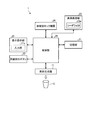
- FIG. 2 is a block diagram schematically illustrating a control system of the beverage supply device according to the first embodiment of the present invention.
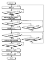
- FIG. 3 is a flowchart showing the contents of processing performed by the control unit shown in FIG.
- FIGS. 4A to 4C are explanatory diagrams showing display examples on the display operation unit.
- FIG. 5 is a perspective view illustrating an external configuration of a beverage supply device according to the second embodiment of the present invention.
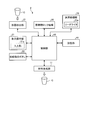
- FIG. 6 is a block diagram schematically illustrating a control system of the beverage supply device according to the second embodiment of the present invention.
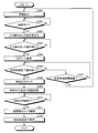
- FIG. 7 is a flowchart illustrating processing performed by the control unit illustrated in FIG. 6.
- FIG. 8 is a perspective view showing an external configuration of a beverage supply device according to Embodiment 3 of the present invention.
- FIG. 9 is a block diagram schematically illustrating a control system of the beverage supply device according to the third embodiment of the present invention.
- FIG. 10 is a flowchart illustrating the processing performed by the control unit illustrated in FIG. 9.
- FIGS. 11A to 11E are explanatory diagrams showing display examples on the display operation unit.
- FIG. 1 is a perspective view showing an external configuration
- FIG. 2 is a block diagram schematically showing a control system.
- the beverage supply device 1 exemplified here is, for example, a coffee machine installed in a store such as a convenience store, and performs, for example, coffee bean grind and extraction processing of dripping, and outputs a beverage such as coffee to a container C such as a cup. Is to supply.
- a beverage supply device 1 includes a main body cabinet 10 and a front door 20.
- the main body cabinet 10 has a substantially rectangular shape with an open front surface. Inside the main body cabinet 10, a beverage producing unit 11 for producing a beverage (for example, coffee) is provided.
- a beverage for example, coffee
- the front door 20 is a door body having a size sufficient to close the opening on the front surface of the main body cabinet 10.
- the front door 20 is provided at one side edge on the front side of the main body cabinet 10 so as to be swingable around a central axis of a shaft (not shown) extending in the up-down direction.
- the opening can be opened and closed.
- the front door 20 has a front side serving as a customer service surface, and includes a display operation unit 21, a supply instruction button 22, a payment processing unit 23, a beverage supply unit 24, and an opening / closing door 25.
- the display operation unit 21 includes, for example, a liquid crystal touch panel, and includes an input unit 21a that displays various information and performs an operation input such as a touch operation.
- the supply instruction button 22 is an input unit for instructing generation and supply of a beverage. Note that the supply instruction button 22 may be a GUI button on the display operation unit 21.
- the settlement processing unit 23 performs settlement processing such as electronic money settlement, for example, and includes a reader / writer 23a that transmits and receives data to and from a portable information terminal such as a smartphone.
- the beverage supply unit 24 is provided below the display operation unit 21 and has a nozzle 24a and a stage 24b.
- the nozzle 24a discharges the beverage generated by the beverage generator 11 downward.
- the stage 24b is provided below the nozzle 24a.
- the stage 24b is for mounting the container C, and has an arc-shaped stopper 24c.
- the door 25 is made of a translucent material such as a transparent resin, for example, and has a size sufficient to cover the entrance 24d of the beverage supply unit 24.
- the opening / closing door 25 has its left end pivotally supported by the front door 20 and can swing in the front-rear direction. That is, the opening / closing door 25 is swingable in the front-rear direction in a manner to approach and separate from the beverage supply unit 24, and when swinging backward in a manner close to the beverage supply unit 24, the entrance of the beverage supply unit 24 24d can be closed, and when swinging forward in a mode separated from the beverage supply unit 24, the entrance 24d of the beverage supply unit 24 can be opened.
- the beverage supply device 1 includes a door opening / closing lock mechanism 26 and a control unit 30.
- the door opening / closing lock mechanism 26 is provided near the entrance 24 d of the beverage supply unit 24.
- This door opening / closing lock mechanism 26 holds a state where the opening / closing door 25 closing the entrance 24d is closed and restricts the opening / closing door 25 from swinging forward. Can be selectively switched between a release state and a release state in which swinging forward is possible.
- the switching of the door opening / closing lock mechanism 26 is performed according to a command given from the control unit 30.
- the control unit 30 is electrically connected to the beverage generation unit 11, the display operation unit 21, the supply instruction button 22, the payment processing unit 23, and the door opening / closing lock mechanism 26, and is also a storage unit that is also electrically connected. In accordance with the programs and data stored in the storage unit 31, the operations of these units are controlled overall.
- the control unit 30 may be realized by executing a program on a processing device such as a CPU (Central Processing Unit), that is, by software, or by hardware such as an IC (Integrated Circuit). Alternatively, it may be realized by using software and hardware together.
- a processing device such as a CPU (Central Processing Unit)
- IC Integrated Circuit
- FIG. 3 is a flowchart showing the processing performed by the control unit 30 shown in FIG. The operation of the beverage supply device 1 will be described while describing the processing content.
- control unit 30 causes the display operation unit 21 to perform a standby display such as "Sellable” (step S101), and waits for a press operation of the supply instruction button 22 (step S101). S102).
- step S102 When the supply instruction button 22 has been pressed (step S102: Yes), the control unit 30 displays on the display operation unit 21 a message indicating that the container C is to be placed in the beverage supply unit 24, and displays a message on the beverage supply unit 24
- the input section 21a is displayed as an indication of intention to arrange the container C (step S103). That is, as shown in FIG. 4B, the input section 21a indicated as "OK” is displayed while "Please set the container” is displayed.
- step S104, step S105 determines whether or not the input unit 21a is operated and input before the preset time elapses after performing the processing of step S103.
- Step S104 No, Step S105: Yes
- the control unit 30 returns to the process of Step S101, and causes the display operation unit 21 to perform standby display.
- Step S104 when the operation input is performed before the set time elapses (Step S104: Yes, Step S105: No), the control unit 30 locks the open / close door 25 to the closed state using the door open / close lock mechanism 26.
- Step S106 it is determined whether or not the payment processing is performed by the payment processing unit 23 before the preset payment standby time elapses after the processing of Step S106 is performed (Step S107, Step S107). S108).
- Step S107: No, Step S108: Yes the control unit 30 sets the closed state of the open / close door 25 by the door open / close lock mechanism 26.
- the lock is released, and the process returns to step S101 to cause the display operation unit 21 to perform standby display.
- Step S107 when the payment processing is performed by the payment processing unit 23 before the payment standby time elapses (Step S107: Yes, Step S108: No), the control unit 30 supplies the beverage to the beverage generation unit 11. The process of producing and supplying the beverage to be performed is performed (step S109).
- the control unit 30 determines whether or not the beverage supply by the beverage generation unit 11 has been completed (step S110). When the beverage supply has not been completed (Step S110: No), the control unit 30 returns to Step S109 and continues the beverage generation and supply processing. On the other hand, when the beverage supply ends (Step S110: Yes), the control unit 30 unlocks the closed state of the opening / closing door 25 by the door opening / closing lock mechanism 26 (Step S111), and shows in FIG. 4C. Thus, the display of the removal of the container C is displayed as in the case of “container removal” (step S112), and then the current process is terminated.
- the control unit 30 places the container C on the display operation unit 21 when the supply instruction button 22 is pressed.
- the input section 21a is displayed as an indication of the intention to arrange the container C on the beverage supply section 24, and the input section 21a is operated and input, the beverage generation section is displayed. Since the beverage generated in 11 is supplied to the container C, not only is the user prompted to arrange the container C by the beverage supply unit 24, but also the input unit 21a is operated to make the user recognize the arrangement of the container C strongly. Accordingly, it is possible to prevent the beverage from being supplied without disposing the container C in the beverage supply unit 24.
- the door 25 that opens and closes the entrance 24d of the beverage supply unit 24 is provided.
- the door 25 may not be provided. In that case, in the processing shown in FIG. 3, the processing of step S106 and step S111 may be omitted.
- FIG. 5 and 6 show a beverage supply device according to a second embodiment of the present invention.
- FIG. 5 is a perspective view showing an external configuration
- FIG. 6 is a block diagram schematically showing a control system.
- the beverage supply device 2 illustrated here is, for example, a coffee machine installed in a store such as a convenience store, and performs, for example, coffee bean grind and extraction processing of dripping, and outputs a beverage such as coffee to a container C such as a cup. Is to supply.
- a beverage supply device 2 includes a main body cabinet 10 and a front door 20.
- the main body cabinet 10 has a substantially rectangular shape with an open front surface. Inside the main body cabinet 10, a beverage producing unit 11 for producing a beverage (for example, coffee) is provided.
- a beverage for example, coffee
- the front door 20 is a door body having a size sufficient to close the opening on the front surface of the main body cabinet 10.
- the front door 20 is provided at one side edge on the front side of the main body cabinet 10 so as to be swingable around a central axis of a shaft (not shown) extending in the up-down direction.
- the opening can be opened and closed.
- the front door 20 has a front side serving as a customer service surface, and includes a display operation unit 21, a supply instruction button 22, a payment processing unit 23, a beverage supply unit 24, and an opening / closing door 25.
- the display operation unit 21 includes, for example, a liquid crystal touch panel, and includes an input unit 21a that displays various information and performs an operation input such as a touch operation.
- the supply instruction button 22 is an input unit for instructing generation and supply of a beverage. Note that the supply instruction button 22 may be a GUI button on the display operation unit 21.
- the settlement processing unit 23 performs settlement processing such as electronic money settlement, for example, and includes a reader / writer 23a that transmits and receives data to and from a portable information terminal such as a smartphone.
- the beverage supply unit 24 is provided below the display operation unit 21 and has a nozzle 24a and a stage 24b.
- the nozzle 24a discharges the beverage generated by the beverage generator 11 downward.
- the stage 24b is provided below the nozzle 24a.
- the stage 24b is for mounting the container C, and has an arc-shaped stopper 24c.
- the door 25 is made of a translucent material such as a transparent resin, for example, and has a size sufficient to cover the entrance 24d of the beverage supply unit 24.
- the opening / closing door 25 has its left end pivotally supported by the front door 20 and can swing in the front-rear direction. That is, the opening / closing door 25 is swingable in the front-rear direction in a manner to approach and separate from the beverage supply unit 24, and when swinging backward in a manner close to the beverage supply unit 24, the entrance of the beverage supply unit 24 24d can be closed, and when swinging forward in a mode separated from the beverage supply unit 24, the entrance 24d of the beverage supply unit 24 can be opened.
- the beverage supply device 2 includes a door opening / closing lock mechanism 26, a container detection unit 27, and a control unit 40.
- the container detection unit 27 is configured by, for example, an optical sensor or the like, and detects whether or not the container C is disposed in the beverage supply unit 24, that is, whether or not the container C is placed on the stage 24b.
- the container detection section 27 gives the detection result of the presence or absence of the container C to the control section 40.
- the control unit 40 is electrically connected to the beverage generation unit 11, the display operation unit 21, the supply instruction button 22, the payment processing unit 23, the container detection unit 27, and the door opening / closing lock mechanism 26. In accordance with programs and data stored in the connected storage unit 41, the operations of these units are generally controlled.
- the control unit 40 may be realized, for example, by causing a processing device such as a CPU (Central Processing Unit) to execute a program, that is, by a software or by a hardware such as an IC (Integrated Circuit). Alternatively, it may be realized by using software and hardware together.
- a processing device such as a CPU (Central Processing Unit)
- a program that is, by a software or by a hardware such as an IC (Integrated Circuit).
- IC Integrated Circuit
- FIG. 7 is a flowchart showing the processing performed by the control unit 40 shown in FIG. The operation of the beverage supply device 2 will be described while describing such processing contents.
- the control unit 40 causes the display operation unit 21 to perform a standby display such as “Sellable” (step S201), and determines whether the container detection unit 27 has detected that the container C is present in the beverage supply unit 24. (Step S202). That is, the container detection unit 27 detects whether the container C is mounted on the stage 24b.
- Step S202 When it is detected that the container C is present (Step S202: Yes), the control unit 40 activates the supply instruction button 22, that is, enters a state in which a press operation of the supply instruction button 22 can be received (Step S203), and The operation waits for the button 22 to be pressed (step S204). On the other hand, when it is not detected that the container C is present (Step S202: No), the control unit 40 repeats the determination processing of Step S202. In this case, the control unit 40 disables the supply instruction button 22, that is, enters a state in which the operation of pressing the supply instruction button 22 cannot be accepted.
- step S204 When the supply instruction button 22 has been pressed (step S204: Yes), the control unit 40 locks the door 25 in the closed state using the door opening / closing lock mechanism 26 (step S205), and performs the processing of step S205. Then, it is determined whether or not payment processing has been performed by the payment processing unit 23 before the preset payment standby time elapses (steps S206 and S207).
- Step S206 No, Step S207: Yes
- the control unit 40 sets the closed state of the open / close door 25 by the door open / close lock mechanism 26.
- the lock is released, and the process returns to step S201 to cause the display operation unit 21 to perform standby display.
- Step S206 when the payment processing is performed by the payment processing unit 23 before the payment standby time elapses (Step S206: Yes, Step S207: No), the control unit 40 supplies the beverage to the beverage generation unit 11. The process of producing and supplying the beverage to be performed is performed (step S208).
- the control unit 40 determines whether or not the beverage supply by the beverage generation unit 11 has been completed (Step S209). If the beverage supply has not been completed (step S209: No), the control unit 40 returns to step S208 and continues the beverage generation and supply processing. On the other hand, when the beverage supply is completed (Step S209: Yes), the control unit 40 unlocks the closed state of the opening / closing door 25 by the door opening / closing lock mechanism 26 (Step S210), and performs a process such as “container removal”. To display the removal of the container C (step S211), and thereafter, the current process ends.
- the control unit 40 activates the supply instruction button 22 when the arrangement of the container C is detected by the container detection unit 27. Since the beverage generated by the beverage generation unit 11 is supplied to the container C by pressing the activated and activated supply instruction button 22, the beverage is supplied without disposing the container C in the beverage supply unit 24. Can be suppressed.
- the door 25 that opens and closes the entrance 24d of the beverage supply unit 24 is provided.
- the door 25 may not be provided. In that case, in the processing shown in FIG. 7, the processing of step S205 and step S210 may be omitted.
- FIG. 8 and 9 show a beverage supply apparatus according to Embodiment 3 of the present invention.
- FIG. 8 is a perspective view showing an external configuration
- FIG. 9 is a block diagram schematically showing a control system.
- the beverage supply device 3 exemplified here is, for example, a coffee machine installed in a store such as a convenience store, and performs, for example, coffee bean grind and extraction processing of dripping, and stores a beverage such as coffee in a container C such as a cup. Is to supply.
- a beverage supply device 3 includes a main body cabinet 10 and a front door 20a.
- the main body cabinet 10 has a substantially rectangular shape with an open front surface. Inside the main body cabinet 10, a beverage producing unit 11 for producing a beverage (for example, coffee) is provided.
- a beverage for example, coffee
- the front door 20a is a door having a size sufficient to close the opening on the front surface of the main body cabinet 10.
- the front door 20a is provided at one side edge on the front side of the main body cabinet 10 so as to be swingable about a central axis of a shaft (not shown) extending along the vertical direction.
- the opening can be opened and closed.
- the front door 20a has a front side serving as a customer service surface, and is provided with a display operation unit 21, a beverage supply unit 24, and an opening / closing door 25.
- the display operation unit 21 includes, for example, a liquid crystal touch panel, and includes an input unit 21a that displays various information and performs an operation input such as a touch operation.
- the input unit 21a also has a function of a supply instruction button for instructing generation and supply of the beverage.
- the beverage supply unit 24 is provided below the display operation unit 21 and has a nozzle 24a and a stage 24b.
- the nozzle 24a discharges the beverage generated by the beverage generator 11 downward.
- the stage 24b is provided below the nozzle 24a.
- the stage 24b is for mounting the container C, and has an arc-shaped stopper 24c.
- the door 25 is made of a translucent material such as a transparent resin, for example, and has a size sufficient to cover the entrance 24d of the beverage supply unit 24.
- the opening / closing door 25 has its left end pivotally supported by the front door 20a, and can swing in the front-rear direction. That is, the opening / closing door 25 is swingable in the front-rear direction in a manner to approach and separate from the beverage supply unit 24, and when swinging backward in a manner close to the beverage supply unit 24, the entrance of the beverage supply unit 24 24d can be closed, and when swinging forward in a mode separated from the beverage supply unit 24, the entrance 24d of the beverage supply unit 24 can be opened.
- the beverage supply device 3 includes a door opening / closing lock mechanism 26, a container detection unit 27, and a control unit 50.
- the container detection unit 27 is configured by, for example, an optical sensor or the like, and detects whether or not the container C is disposed in the beverage supply unit 24, that is, whether or not the container C is placed on the stage 24b.
- the container detection unit 27 gives the detection result of the presence or absence of the container C to the control unit 50.
- the control unit 50 is electrically connected to the beverage generating unit 11, the display operation unit 21, the container detection unit 27, and the door opening / closing lock mechanism 26, and is stored in the storage unit 51 which is also electrically connected. In accordance with programs and data, the operations of these units are controlled overall.
- the control unit 50 may be realized by, for example, causing a processing device such as a CPU (Central Processing Unit) to execute a program, that is, realized by software, or realized by hardware such as an IC (Integrated Circuit). Alternatively, it may be realized by using software and hardware together.
- FIG. 10 is a flowchart showing the processing performed by the control unit 50 shown in FIG. The operation of the beverage supply device 3 will be described while describing such processing contents.
- the control unit 50 displays the word “Place a container” on the display operation unit 21 as shown in FIG. 11A, and also inputs an instruction to supply “beverage 1” and “beverage 2”.
- a standby display for displaying 21a is performed (step S301), and it is determined whether or not the container detection unit 27 has detected that the container C is in the beverage supply unit 24 (step S302). That is, the container detection unit 27 detects whether the container C is mounted on the stage 24b.
- Step S302 When it is detected that the container C is present (Step S302: Yes), the control unit 50 causes the display operation unit 21 to display the word "Please select a beverage" as shown in FIG. 11B. Meanwhile, the input unit 21a for supplying instructions is enabled, that is, the input operation of each input unit 21a can be accepted (input operation) (step S303), and the input unit 21a waits for the touch operation (step S304).
- Step S302 when the presence of the container C is not detected (Step S302: No), the control unit 50 repeats the determination processing of Step S302. In this case, the control unit 50 invalidates the supply instruction input unit 21a, that is, enters a state in which the touch operation of the input unit 21a cannot be accepted.
- Step S304 Yes
- the control unit 50 performs A QR code (registered trademark) for settlement is displayed on the display operation unit 21 while displaying the words "Beverage is extracted after payment” (step S305).
- the control unit 50 displaying the QR code (registered trademark) in this manner transmits a payment processing completion notification to a predetermined communication unit before the predetermined payment standby time elapses after performing the processing of step S305. Then, it is determined whether or not the input has been made (steps S306 and S307). Although not shown in the figure, such a communication unit is connected to a communication line such as a network and transmits and receives data.
- the user can read the QR code (registered trademark) with a portable information terminal such as a smartphone and communicate with the server that performs the payment process. To perform the settlement process.
- step S306 If the payment standby time has elapsed without receiving a payment processing completion notification indicating that the payment processing has been properly performed from the mobile terminal device via the communication unit (step S306: No, step S307: Yes), the process proceeds to step S301. Returning to the processing, the display operation unit 21 is caused to perform standby display.
- step S306 when a payment processing completion notification indicating that the payment processing has been properly performed is input from the portable terminal device via the communication unit before the payment standby time elapses (step S306: Yes, step S307: No). That is, when the predetermined payment process is completed, the control unit 50 locks the open / close door 25 to the closed state using the door open / close lock mechanism 26 (Step S308).
- control part 50 makes the beverage production
- control unit 50 determines whether or not the beverage supply by the beverage generation unit 11 has been completed (Step S310). If the beverage supply has not been completed (Step S310: No), the control unit 50 returns to Step S309 and continues the processing of the beverage generation and supply.
- step S310 Yes
- the control unit 50 unlocks the closed state of the opening / closing door 25 by the door opening / closing lock mechanism 26 (step S311), and (e) of FIG.
- step S312 a beverage supply end display for displaying the word "drink is ready" on the display operation unit 21 is performed (step S312), and then the current process is terminated.
- the control unit 50 activates the input unit 21a when the arrangement of the container C is detected by the container detection unit 27.
- the input unit 21a that has been activated is touch-operated, the beverage generated by the beverage generation unit 11 is supplied to the container C, so that the beverage is supplied without disposing the container C in the beverage supply unit 24. Can be suppressed.
- the door 25 that opens and closes the entrance 24d of the beverage supply unit 24 is provided.
- the door 25 may not be provided. In that case, in the processing shown in FIG. 10, the processing of steps S308 and S311 may be omitted.
- a cancel button for instructing cancellation of the settlement process may be provided in the present invention. If such a cancel button is provided, it is possible to return to the standby state when the cancel button is pressed, and it is not necessary for the user to wait for the payment standby time to elapse, thereby improving convenience. Can be achieved.
- the settlement processing unit 23 is provided as an element constituting the beverage supply devices 1 and 2, but in the beverage supply device according to the present invention, the settlement processing unit 23 is It does not have to be provided.
- the beverage supply device displays a QR code (registered trademark) on the display operation unit instead of steps S107 and S206 in FIGS. 3 and 7, and reads the QR code (registered trademark). What is necessary is just to judge whether or not the appropriate payment processing between the mobile information terminal and the server that performs the payment processing is provided by the mobile information terminal. Then, when it is determined that the payment processing has been performed by the portable information terminal, the processing of steps S109 and S208 may be performed.
- QR code registered trademark
- an opening / closing sensor that detects opening / closing of the inlet 24d of the beverage supply unit 24 may be provided.
- the opening / closing sensor is turned on when the door 25 swings forward and the entrance 24d is opened, and provides an ON signal to the control unit 50.
- the opening / closing door 25 swings rearward to enter the entrance 24d. Is turned off when the switch is closed, thereby restricting the transmission of the on signal.
- SYMBOLS 1 ... Beverage supply apparatus, 10 ... Main body cabinet, 11 ... Beverage production part, 20 ... Front door, 21 ... Display operation part, 21a ... Input part, 22 ... Supply instruction button, 23 ... Settlement processing part, 24 ... Beverage supply part .., 24a ... nozzle, 24b ... stage, 24c ... stopper, 24d ... entrance, 25 ... open / close door, 26 ... door open / close lock mechanism, 30 ... control unit, 31 ... memory unit, C ... container.
Landscapes
- Engineering & Computer Science (AREA)
- Food Science & Technology (AREA)
- Physics & Mathematics (AREA)
- General Physics & Mathematics (AREA)
- Apparatus For Making Beverages (AREA)
- Devices For Dispensing Beverages (AREA)
Abstract
飲料供給部(24)に配置された容器(C)に対して、飲料生成部(11)で生成した飲料を供給する飲料供給装置(1)であって、飲料の生成及び供給を指示する供給指示ボタン(22)と、与えられた指令に基づいて表示を行うとともに、操作入力が可能な表示操作部(21)と、供給指示ボタン(22)が押下操作されたことを契機として、表示操作部(21)に容器(C)を飲料供給部(24)に配置する旨の表示、並びに飲料供給部(24)に容器(C)を配置した意思表示としての入力部(21a)の表示を行わせ、入力部(21a)が操作入力された場合に、飲料生成部(11)で生成した飲料を容器(C)に供給させる制御部(30)を備えている。
Description
本発明は、飲料供給装置に関し、より詳細には、例えばコンビニエンスストア等の店舗に設置されるコーヒーマシン等の飲料供給装置に関するものである。
従来、例えばコンビニエンスストア等の店舗には、コーヒーマシン等の飲料供給装置が設置されている。飲料供給装置は、例えばコーヒー豆挽き及びドリッピングの抽出処理等の処理を行って飲料を生成し、例えばカップ等の容器に対して飲料を供給するものである。
そのような飲料供給装置では、飲料の生成及び供給を指示する供給指示ボタンが押下操作されると、容器に対して飲料の供給を行っている(例えば、特許文献1参照)。
ところで、上述した飲料供給装置では、供給指示ボタンが押下操作されると飲料の供給を行っているので、利用者が容器を所定の飲料供給部に配置しないで供給指示ボタンを押下操作してしまうと、生成した飲料が容器に供給されずに吐出されてしまう虞れがあった。このように飲料が吐出されてしまうと、利用者が不利益を被るだけでなく、生成した飲料の無駄になり好ましくない。
本発明は、上記実情に鑑みて、飲料供給部に容器が配置されないで飲料が供給されてしまうことを抑制することができる飲料供給装置を提供することを目的とする。
上記目的を達成するために、本発明に係る飲料供給装置は、飲料供給部に配置された容器に対して、飲料生成部で生成した飲料を供給する飲料供給装置であって、飲料の生成及び供給を指示する供給指示ボタンと、与えられた指令に基づいて表示を行うとともに、操作入力が可能な表示操作部と、前記供給指示ボタンが押下操作されたことを契機として、前記表示操作部に容器を飲料供給部に配置する旨の表示、並びに飲料供給部に容器を配置した意思表示としての入力部の表示を行わせ、該入力部が操作入力された場合に、前記飲料生成部で生成した飲料を前記容器に供給させる制御部とを備えたことを特徴とする。
また本発明は、上記飲料供給装置において、前記制御部は、前記入力部が操作入力された場合に、所定の決済処理が終了したことを条件として前記飲料生成部で生成した飲料を前記容器に供給させることを特徴とする。
また本発明は、上記飲料供給装置において、前記飲料供給部の入口を開閉する開閉扉と、前記入口を閉成する前記開閉扉が閉となる状態に保持するロック状態と、該開閉扉が前記入口を開成することを許容する解除状態との間で択一的に切り替え可能な扉開閉ロック機構とを備え、前記制御部は、前記入力部が操作入力された場合に、前記扉開閉ロック機構をロック状態にさせてから所定の決済処理が終了したことを条件として前記飲料生成部で生成した飲料を前記容器に供給させ、該飲料の供給後に扉開閉ロック機構を解除状態にさせることを特徴とする。
また、本発明に係る飲料供給装置は、飲料供給部に配置された容器に対して、飲料生成部で生成した飲料を供給する飲料供給装置であって、前記飲料供給部に前記容器が配置されたことを検出する容器検出部と、飲料の生成及び供給を指示する供給指示ボタンと、前記容器検出部により前記容器の配置が検出された場合には、前記供給指示ボタンを有効化させる一方、前記容器検出部により前記容器の配置が検出されない場合には、前記供給指示ボタンを無効化させる制御部とを備え、前記制御部は、有効化させた前記供給指示ボタンが押下操作された場合に、前記飲料生成部で生成した飲料を前記容器に供給させることを特徴とする。
また本発明は、上記飲料供給装置において、前記制御部は、有効化させた前記供給指示ボタンが押下操作された場合に、所定の決済処理が終了したことを条件として前記飲料生成部で生成した飲料を前記容器に供給させることを特徴とする。
また本発明は、上記飲料供給装置において、前記飲料供給部の入口を開閉する開閉扉と、前記入口を閉成する前記開閉扉が閉となる状態に保持するロック状態と、該開閉扉が前記入口を開成することを許容する解除状態との間で択一的に切り替え可能な扉開閉ロック機構とを備え、前記制御部は、有効化させた前記供給指示ボタンが押下操作された場合に、前記扉開閉ロック機構をロック状態にさせてから所定の決済処理が終了したことを条件として前記飲料生成部で生成した飲料を前記容器に供給させ、該飲料の供給後に扉開閉ロック機構を解除状態にさせることを特徴とする。
また本発明は、上記飲料供給装置において、前記飲料供給部の入口を開閉する開閉扉と、前記入口を閉成する前記開閉扉が閉となる状態に保持するロック状態と、該開閉扉が前記入口を開成することを許容する解除状態との間で択一的に切り替え可能な扉開閉ロック機構とを備え、前記制御部は、有効化させた前記供給指示ボタンが押下操作された場合に、所定の決済処理が終了したことを条件として前記扉開閉ロック機構をロック状態にさせ、前記飲料生成部で生成した飲料を前記容器に供給させ、該飲料の供給後に扉開閉ロック機構を解除状態にさせることを特徴とする。
本発明によれば、制御部が、供給指示ボタンが押下操作されたことを契機として、表示操作部に容器を飲料供給部に配置する旨の表示、並びに飲料供給部に容器を配置した意思表示としての入力部の表示を行わせ、該入力部が操作入力された場合に、飲料生成部で生成した飲料を容器に供給させるので、利用者に対して飲料供給部に容器の配置を促すだけでなく、入力部を入力操作させることで容器の配置を強く認識させることができ、これにより、飲料供給部に容器が配置されないで飲料が供給されてしまうことを抑制することができるという効果を奏する。
また本発明によれば、制御部が、容器検出部により容器の配置が検出された場合には供給指示ボタンを有効化させ、有効化させた供給指示ボタンが押下操作されることで、飲料生成部で生成した飲料を容器に供給させるので、飲料供給部に容器が配置されないで飲料が供給されてしまうことを抑制することができるという効果を奏する。
以下に添付図面を参照して、本発明に係る飲料供給装置の好適な実施の形態について詳細に説明する。
<実施の形態1>
図1及び図2は、それぞれ本発明の実施の形態1である飲料供給装置を示すもので、図1は、外観構成を示す斜視図であり、図2は、制御系を模式的に示すブロック図である。ここで例示する飲料供給装置1は、例えばコンビニエンスストア等の店舗に設置されるコーヒーマシンであり、例えばコーヒー豆挽き及びドリッピングの抽出処理を行って、例えばカップ等の容器Cにコーヒー等の飲料を供給するものである。このような飲料供給装置1は、本体キャビネット10及び前面扉20を備えている。
図1及び図2は、それぞれ本発明の実施の形態1である飲料供給装置を示すもので、図1は、外観構成を示す斜視図であり、図2は、制御系を模式的に示すブロック図である。ここで例示する飲料供給装置1は、例えばコンビニエンスストア等の店舗に設置されるコーヒーマシンであり、例えばコーヒー豆挽き及びドリッピングの抽出処理を行って、例えばカップ等の容器Cにコーヒー等の飲料を供給するものである。このような飲料供給装置1は、本体キャビネット10及び前面扉20を備えている。
本体キャビネット10は、前面が開口した略直方状の形態を成すものである。この本体キャビネット10の内部には、飲料(例えばコーヒー)を生成する飲料生成部11が設けてある。
前面扉20は、本体キャビネット10の前面の開口を閉塞するのに十分な大きさを有する扉体である。この前面扉20は、本体キャビネット10の前方側一側縁部において、上下方向に沿って延在する図示せぬ軸部の中心軸回りに揺動可能に設けてあり、本体キャビネット10の前面の開口を開閉することが可能である。
かかる前面扉20は、前面が接客面を構成しており、表示操作部21、供給指示ボタン22、決済処理部23、飲料供給部24及び開閉扉25が設けてある。
表示操作部21は、例えば液晶タッチパネルで構成してあり、各種情報を表示するとともに、タッチ操作等の操作入力を行う入力部21aを有している。供給指示ボタン22は、飲料の生成及び供給を指示するための入力手段である。尚、供給指示ボタン22は、表示操作部21上のGUIボタンであってもよい。
決済処理部23は、例えば電子マネー決済等の決済処理を行うものであり、例えばスマートフォン等の携帯情報端末との間でデータの送受信を行うリーダライタ23aを備えている。
飲料供給部24は、表示操作部21の下方側に設けてあり、ノズル24aとステージ24bとを有している。ノズル24aは、飲料生成部11で生成された飲料を下方に向けて吐出するものである。ステージ24bは、ノズル24aの下方域に設けてある。このステージ24bは、容器Cを載置させるものであり、円弧状のストッパ24cが設けてある。
開閉扉25は、例えば透明な樹脂等の透光性材料により構成されるものであり、飲料供給部24の入口24dを覆うのに十分な大きさを有している。この開閉扉25は、左側端部が前面扉20に軸支されており、前後方向に沿って揺動可能なものである。つまり、開閉扉25は、飲料供給部24に近接離反する態様で前後方向に沿って揺動可能であり、飲料供給部24に近接する態様で後方に揺動する場合に飲料供給部24の入口24dを閉成させることが可能であり、飲料供給部24から離隔する態様で前方に揺動する場合に飲料供給部24の入口24dを開成させることが可能である。
図2に示すように、飲料供給装置1は、扉開閉ロック機構26及び制御部30を備えている。扉開閉ロック機構26は、飲料供給部24の入口24dの近傍に設けてある。この扉開閉ロック機構26は、入口24dを閉成する開閉扉25が閉となる状態を保持させて該開閉扉25が前方に向けて揺動することを規制するロック状態と、該開閉扉25が前方に向けて揺動することを許容する解除状態との間で択一的に切替可能なものである。かかる扉開閉ロック機構26の切り替えは、制御部30から与えられる指令に応じて行われる。
制御部30は、上述した飲料生成部11、表示操作部21、供給指示ボタン22、決済処理部23、扉開閉ロック機構26に電気的に接続してあり、同じく電気的に接続された記憶部31に記憶されたプログラムやデータに従って、これら各部の動作を統括的に制御するものである。尚、制御部30は、例えば、CPU(Central Processing Unit)等の処理装置にプログラムを実行させること、すなわち、ソフトウェアにより実現してもよいし、IC(Integrated Circuit)等のハードウェアにより実現してもよいし、ソフトウェア及びハードウェアを併用して実現してもよい。
図3は、図2に示した制御部30が実施する処理内容を示すフローチャートである。かかる処理内容を説明しながら飲料供給装置1の動作について説明する。
制御部30は、図4の(a)に示すように、表示操作部21に「販売可」のように待機表示を行わせ(ステップS101)、供給指示ボタン22の押下操作待ちとなる(ステップS102)。
供給指示ボタン22が押下操作された場合(ステップS102:Yes)、制御部30は、表示操作部21に対して、容器Cを飲料供給部24に配置する旨の表示、並びに飲料供給部24に容器Cを配置した意思表示としての入力部21aの表示を行わせる(ステップS103)。すなわち、図4の(b)に示すように、「容器セットしてください」と表示させつつ、「OK」と示された入力部21aを表示させる。そして、制御部30は、ステップS103の処理を実施してから予め設定された設定時間が経過するまでに入力部21aが操作入力されるか否かを判断する(ステップS104,ステップS105)。
操作入力されることなく設定時間が経過した場合(ステップS104:No,ステップS105:Yes)、制御部30は、ステップS101の処理に戻って、表示操作部21に待機表示を行わせる。
その一方、設定時間が経過するまでに操作入力が行われた場合(ステップS104:Yes,ステップS105:No)、制御部30は、扉開閉ロック機構26を用いて開閉扉25を閉状態にロックし(ステップS106)、ステップS106の処理を実施してから予め設定された決済待機時間が経過するまでに、決済処理部23にて決済処理が行われたか否かを判断する(ステップS107,ステップS108)。
決済処理部23にて決済処理が行われることなく決済待機時間が経過した場合(ステップS107:No,ステップS108:Yes)、制御部30は、扉開閉ロック機構26による開閉扉25の閉状態のロックを解除してステップS101の処理に戻り、表示操作部21に待機表示を行わせる。
その一方、決済待機時間が経過するまでに決済処理部23にて決済処理が行われた場合(ステップS107:Yes,ステップS108:No)、制御部30は、飲料生成部11に対して、供給する飲料の生成及び供給の処理を行わせる(ステップS109)。
その後、制御部30は、飲料生成部11による飲料供給が終了したか否かを判断する(ステップS110)。飲料供給が終了していない場合(ステップS110:No)、制御部30は、ステップS109に戻って飲料の生成及び供給の処理を続行する。一方、飲料供給が終了した場合(ステップS110:Yes)、制御部30は、扉開閉ロック機構26による開閉扉25の閉状態のロックを解除し(ステップS111)、図4の(c)に示すように、「容器取出し」のように容器Cの取出しの表示を行わせ(ステップS112)、その後に今回の処理を終了する。
以上説明したように、本発明の実施の形態1である飲料供給装置1によれば、制御部30が、供給指示ボタン22が押下操作されたことを契機として、表示操作部21に容器Cを飲料供給部24に配置する旨の表示、並びに飲料供給部24に容器Cを配置した意思表示としての入力部21aの表示を行わせ、該入力部21aが操作入力された場合に、飲料生成部11で生成した飲料を容器Cに供給させるので、利用者に対して飲料供給部24に容器Cの配置を促すだけでなく、入力部21aを入力操作させることで容器Cの配置を強く認識させることができ、これにより、飲料供給部24に容器Cが配置されないで飲料が供給されてしまうことを抑制することができる。
上述した実施の形態1では、飲料供給部24の入口24dを開閉する開閉扉25が設けられていたが、本発明においては、開閉扉25が設けられていなくてもよい。その場合には、図3に示す処理において、ステップS106及びステップS111の処理を省略すればよい。
<実施の形態2>
図5及び図6は、それぞれ本発明の実施の形態2である飲料供給装置を示すもので、図5は、外観構成を示す斜視図であり、図6は、制御系を模式的に示すブロック図である。尚、上述した実施の形態1と同様の構成要素については同一の符号を付してその説明を適宜省略する。
図5及び図6は、それぞれ本発明の実施の形態2である飲料供給装置を示すもので、図5は、外観構成を示す斜視図であり、図6は、制御系を模式的に示すブロック図である。尚、上述した実施の形態1と同様の構成要素については同一の符号を付してその説明を適宜省略する。
ここで例示する飲料供給装置2は、例えばコンビニエンスストア等の店舗に設置されるコーヒーマシンであり、例えばコーヒー豆挽き及びドリッピングの抽出処理を行って、例えばカップ等の容器Cにコーヒー等の飲料を供給するものである。このような飲料供給装置2は、本体キャビネット10及び前面扉20を備えている。
本体キャビネット10は、前面が開口した略直方状の形態を成すものである。この本体キャビネット10の内部には、飲料(例えばコーヒー)を生成する飲料生成部11が設けてある。
前面扉20は、本体キャビネット10の前面の開口を閉塞するのに十分な大きさを有する扉体である。この前面扉20は、本体キャビネット10の前方側一側縁部において、上下方向に沿って延在する図示せぬ軸部の中心軸回りに揺動可能に設けてあり、本体キャビネット10の前面の開口を開閉することが可能である。
かかる前面扉20は、前面が接客面を構成しており、表示操作部21、供給指示ボタン22、決済処理部23、飲料供給部24及び開閉扉25が設けてある。
表示操作部21は、例えば液晶タッチパネルで構成してあり、各種情報を表示するとともに、タッチ操作等の操作入力を行う入力部21aを有している。供給指示ボタン22は、飲料の生成及び供給を指示するための入力手段である。尚、供給指示ボタン22は、表示操作部21上のGUIボタンであってもよい。
決済処理部23は、例えば電子マネー決済等の決済処理を行うものであり、例えばスマートフォン等の携帯情報端末との間でデータの送受信を行うリーダライタ23aを備えている。
飲料供給部24は、表示操作部21の下方側に設けてあり、ノズル24aとステージ24bとを有している。ノズル24aは、飲料生成部11で生成された飲料を下方に向けて吐出するものである。ステージ24bは、ノズル24aの下方域に設けてある。このステージ24bは、容器Cを載置させるものであり、円弧状のストッパ24cが設けてある。
開閉扉25は、例えば透明な樹脂等の透光性材料により構成されるものであり、飲料供給部24の入口24dを覆うのに十分な大きさを有している。この開閉扉25は、左側端部が前面扉20に軸支されており、前後方向に沿って揺動可能なものである。つまり、開閉扉25は、飲料供給部24に近接離反する態様で前後方向に沿って揺動可能であり、飲料供給部24に近接する態様で後方に揺動する場合に飲料供給部24の入口24dを閉成させることが可能であり、飲料供給部24から離隔する態様で前方に揺動する場合に飲料供給部24の入口24dを開成させることが可能である。
図6に示すように、飲料供給装置2は、扉開閉ロック機構26、容器検出部27及び制御部40を備えている。
容器検出部27は、例えば光センサ等により構成されるもので、飲料供給部24における容器Cの配置の有無、すなわちステージ24bに容器Cが載置されたか否かを検出するものである。この容器検出部27は、容器Cの有無の検出結果を制御部40に与えるものである。
制御部40は、上述した飲料生成部11、表示操作部21、供給指示ボタン22、決済処理部23、容器検出部27、扉開閉ロック機構26に電気的に接続してあり、同じく電気的に接続された記憶部41に記憶されたプログラムやデータに従って、これら各部の動作を統括的に制御するものである。尚、制御部40は、例えば、CPU(Central Processing Unit)等の処理装置にプログラムを実行させること、すなわち、ソフトウェアにより実現してもよいし、IC(Integrated Circuit)等のハードウェアにより実現してもよいし、ソフトウェア及びハードウェアを併用して実現してもよい。
図7は、図6に示した制御部40が実施する処理内容を示すフローチャートである。かかる処理内容を説明しながら飲料供給装置2の動作について説明する。
制御部40は、表示操作部21に「販売可」のように待機表示を行わせ(ステップS201)、容器検出部27が、容器Cが飲料供給部24に有ると検出したか否かを判断する(ステップS202)。すなわち、容器検出部27が、容器Cがステージ24bに載置されたか否かを検出する。
容器Cが有ると検出された場合(ステップS202:Yes)、制御部40は、供給指示ボタン22を有効化、すなわち供給指示ボタン22の押下操作の受付可能状態になり(ステップS203)、供給指示ボタン22の押下操作待ちとなる(ステップS204)。一方、容器Cが有ると検出されない場合(ステップS202:No)、制御部40は、ステップS202の判断処理を繰り返す。この場合、制御部40は、供給指示ボタン22を無効化、すなわち、供給指示ボタン22の押下操作を受付不可状態となる。
供給指示ボタン22が押下操作された場合(ステップS204:Yes)、制御部40は、扉開閉ロック機構26を用いて開閉扉25を閉状態にロックし(ステップS205)、ステップS205の処理を実施してから予め設定された決済待機時間が経過するまでに、決済処理部23にて決済処理が行われたか否かを判断する(ステップS206,ステップS207)。
決済処理部23にて決済処理が行われることなく決済待機時間が経過した場合(ステップS206:No,ステップS207:Yes)、制御部40は、扉開閉ロック機構26による開閉扉25の閉状態のロックを解除してステップS201の処理に戻り、表示操作部21に待機表示を行わせる。
その一方、決済待機時間が経過するまでに決済処理部23にて決済処理が行われた場合(ステップS206:Yes,ステップS207:No)、制御部40は、飲料生成部11に対して、供給する飲料の生成及び供給の処理を行わせる(ステップS208)。
その後、制御部40は、飲料生成部11による飲料供給が終了したか否かを判断する(ステップS209)。飲料供給が終了していない場合(ステップS209:No)には、制御部40は、ステップS208に戻って飲料の生成及び供給の処理を続行する。一方、飲料供給が終了した場合(ステップS209:Yes)には、制御部40は、扉開閉ロック機構26による開閉扉25の閉状態のロックを解除し(ステップS210)、「容器取出し」のように容器Cの取出しの表示を行わせ(ステップS211)、その後に今回の処理を終了する。
以上説明したように、本発明の実施の形態2である飲料供給装置2によれば、制御部40が、容器検出部27により容器Cの配置が検出された場合には供給指示ボタン22を有効化させ、有効化させた供給指示ボタン22が押下操作されることで、飲料生成部11で生成した飲料を容器Cに供給させるので、飲料供給部24に容器Cが配置されないで飲料が供給されてしまうことを抑制することができる。
上述した実施の形態2では、飲料供給部24の入口24dを開閉する開閉扉25が設けられていたが、本発明においては、開閉扉25が設けられていなくてもよい。その場合には、図7に示す処理において、ステップS205及びステップS210の処理を省略すればよい。
<実施の形態3>
図8及び図9は、それぞれ本発明の実施の形態3である飲料供給装置を示すもので、図8は、外観構成を示す斜視図であり、図9は、制御系を模式的に示すブロック図である。尚、上述した実施の形態1と同様の構成要素については同一の符号を付してその説明を適宜省略する。
図8及び図9は、それぞれ本発明の実施の形態3である飲料供給装置を示すもので、図8は、外観構成を示す斜視図であり、図9は、制御系を模式的に示すブロック図である。尚、上述した実施の形態1と同様の構成要素については同一の符号を付してその説明を適宜省略する。
ここで例示する飲料供給装置3は、例えばコンビニエンスストア等の店舗に設置されるコーヒーマシンであり、例えばコーヒー豆挽き及びドリッピングの抽出処理を行って、例えばカップ等の容器Cにコーヒー等の飲料を供給するものである。このような飲料供給装置3は、本体キャビネット10及び前面扉20aを備えている。
本体キャビネット10は、前面が開口した略直方状の形態を成すものである。この本体キャビネット10の内部には、飲料(例えばコーヒー)を生成する飲料生成部11が設けてある。
前面扉20aは、本体キャビネット10の前面の開口を閉塞するのに十分な大きさを有する扉体である。この前面扉20aは、本体キャビネット10の前方側一側縁部において、上下方向に沿って延在する図示せぬ軸部の中心軸回りに揺動可能に設けてあり、本体キャビネット10の前面の開口を開閉することが可能である。
かかる前面扉20aは、前面が接客面を構成しており、表示操作部21、飲料供給部24及び開閉扉25が設けてある。
表示操作部21は、例えば液晶タッチパネルで構成してあり、各種情報を表示するとともに、タッチ操作等の操作入力を行う入力部21aを有している。この入力部21aは、飲料の生成及び供給を指示するための供給指示ボタンの機能も兼ねている。
飲料供給部24は、表示操作部21の下方側に設けてあり、ノズル24aとステージ24bとを有している。ノズル24aは、飲料生成部11で生成された飲料を下方に向けて吐出するものである。ステージ24bは、ノズル24aの下方域に設けてある。このステージ24bは、容器Cを載置させるものであり、円弧状のストッパ24cが設けてある。
開閉扉25は、例えば透明な樹脂等の透光性材料により構成されるものであり、飲料供給部24の入口24dを覆うのに十分な大きさを有している。この開閉扉25は、左側端部が前面扉20aに軸支されており、前後方向に沿って揺動可能なものである。つまり、開閉扉25は、飲料供給部24に近接離反する態様で前後方向に沿って揺動可能であり、飲料供給部24に近接する態様で後方に揺動する場合に飲料供給部24の入口24dを閉成させることが可能であり、飲料供給部24から離隔する態様で前方に揺動する場合に飲料供給部24の入口24dを開成させることが可能である。
図9に示すように、飲料供給装置3は、扉開閉ロック機構26、容器検出部27及び制御部50を備えている。
容器検出部27は、例えば光センサ等により構成されるもので、飲料供給部24における容器Cの配置の有無、すなわちステージ24bに容器Cが載置されたか否かを検出するものである。この容器検出部27は、容器Cの有無の検出結果を制御部50に与えるものである。
制御部50は、上述した飲料生成部11、表示操作部21、容器検出部27、扉開閉ロック機構26に電気的に接続してあり、同じく電気的に接続された記憶部51に記憶されたプログラムやデータに従って、これら各部の動作を統括的に制御するものである。尚、制御部50は、例えば、CPU(Central Processing Unit)等の処理装置にプログラムを実行させること、すなわち、ソフトウェアにより実現してもよいし、IC(Integrated Circuit)等のハードウェアにより実現してもよいし、ソフトウェア及びハードウェアを併用して実現してもよい。
図10は、図9に示した制御部50が実施する処理内容を示すフローチャートである。かかる処理内容を説明しながら飲料供給装置3の動作について説明する。
制御部50は、図11の(a)に示すように表示操作部21に「容器を置いて下さい」の文言を表示させつつ、「飲料1」及び「飲料2」の供給指示用の入力部21aを表示させる待機表示を行わせ(ステップS301)、容器検出部27が、容器Cが飲料供給部24に有ると検出したか否かを判断する(ステップS302)。すなわち、容器検出部27が、容器Cがステージ24bに載置されたか否かを検出する。
容器Cが有ると検出された場合(ステップS302:Yes)、制御部50は、図11の(b)に示すように、表示操作部21に「飲料を選択して下さい」の文言を表示させつつ、供給指示用の入力部21aを有効化、すなわち各入力部21aのタッチ操作(入力操作)の受付可能状態になり(ステップS303)、入力部21aのタッチ操作待ちとなる(ステップS304)。
一方、容器Cが有ると検出されない場合(ステップS302:No)、制御部50は、ステップS302の判断処理を繰り返す。この場合、制御部50は、供給指示用の入力部21aを無効化、すなわち、入力部21aのタッチ操作を受付不可状態となる。
入力部21aがタッチ操作された場合(ステップS304:Yes)、すなわち、例えば「飲料1」の入力部21aがタッチ操作された場合、制御部50は、図11の(c)に示すように、表示操作部21に「支払後、飲料が抽出されます」の文言を表示させつつ、決済用のQRコード(登録商標)を表示させる(ステップS305)。
このようにQRコード(登録商標)を表示させた制御部50は、ステップS305の処理を実施してから予め設定された決済待機時間が経過するまでに、決済処理完了通知が所定の通信部を介して入力されたか否かを判断する(ステップS306,ステップS307)。かかる通信部は、図には明示していないが、ネットワーク等の通信回線に接続され、データの送受信を行うものである。
このように表示操作部21にQRコード(登録商標)が表示されることで、利用者は、スマートフォン等の携帯情報端末で該QRコード(登録商標)を読み取り、決済処理を行うサーバとの間で決済処理を行うことになる。
決済処理が適正に行われた旨の決済処理完了通知が携帯端末機器より通信部を介して入力されずに決済待機時間が経過した場合(ステップS306:No,ステップS307:Yes)、ステップS301の処理に戻り、表示操作部21に待機表示を行わせる。
その一方、決済待機時間が経過するまでに、決済処理が適正に行われた旨の決済処理完了通知が携帯端末機器より通信部を介して入力された場合(ステップS306:Yes,ステップS307:No)、すなわち、所定の決済処理が終了した場合、制御部50は、扉開閉ロック機構26を用いて開閉扉25を閉状態にロックする(ステップS308)。
そして、制御部50は、飲料生成部11に対して、供給する飲料の生成及び供給の処理を行わせ(ステップS309)、図11の(d)に示すように、表示操作部21に「飲料抽出中・・・」の文言を表示させる。
その後、制御部50は、飲料生成部11による飲料供給が終了したか否かを判断する(ステップS310)。飲料供給が終了していない場合(ステップS310:No)には、制御部50は、ステップS309に戻って飲料の生成及び供給の処理を続行する。
一方、飲料供給が終了した場合(ステップS310:Yes)には、制御部50は、扉開閉ロック機構26による開閉扉25の閉状態のロックを解除し(ステップS311)、図11の(e)に示すように、表示操作部21に「飲料が出来上がりました」の文言を表示させる飲料供給終了表示を行い(ステップS312)、その後に今回の処理を終了する。
以上説明したように、本発明の実施の形態3である飲料供給装置3によれば、制御部50が、容器検出部27により容器Cの配置が検出された場合には入力部21aを有効化させ、有効化させた入力部21aがタッチ操作されることで、飲料生成部11で生成した飲料を容器Cに供給させるので、飲料供給部24に容器Cが配置されないで飲料が供給されてしまうことを抑制することができる。
上述した実施の形態3では、飲料供給部24の入口24dを開閉する開閉扉25が設けられていたが、本発明においては、開閉扉25が設けられていなくてもよい。その場合には、図10に示す処理において、ステップS308及びステップS311の処理を省略すればよい。
以上、本発明の好適な実施の形態1~3について説明したが、本発明はこれらに限定されるものではなく、種々の変更を行うことができる。
上述した実施の形態1~3では述べられていないが、本発明においては、決済処理のキャンセルを指示するためのキャンセルボタンが設けられていてもよい。かかるキャンセルボタンが設けられていると、該キャンセルボタンが押下操作された場合に、待機状態に戻ることができ、利用者に対して決済待機時間の経過を待たせる必要がなく、利便性の向上を図ることができる。
上述した実施の形態1及び実施の形態2においては、飲料供給装置1,2を構成する要素として決済処理部23が設けられていたが、本発明に係る飲料供給装置では、決済処理部23が設けられていなくてもよい。
この場合、飲料供給装置は、図3及び図7のステップS107,ステップS206の代わりに、表示操作部にQRコード(登録商標)を表示し、該QRコード(登録商標)を読み取ったスマートフォン等の携帯情報端末と決済処理を行うサーバとの間で決済処理が適正に行われたことが、該携帯情報端末により与えられたか否かを判断すればよい。そして、携帯情報端末より決済処理が行われたことが与えられたと判断した場合に、ステップS109,ステップS208の処理を実施すればよい。
上述した実施の形態3では述べられていないが、本発明においては、飲料供給部24の入口24dの開閉を検知する開閉センサが設けられていてもよい。この開閉センサは、開閉扉25が前方に揺動して入口24dが開成される場合にオン状態となってオン信号を制御部50に与える一方、開閉扉25が後方に揺動して入口24dが閉成される場合にオフ状態となってオン信号の送出を規制するものである。そのような開閉センサが設けられている場合には、ステップS302で容器Cが有ると検出された場合に、開閉センサがオフ状態となることを条件として、ステップS303の処理を行うことが好ましい。
1…飲料供給装置、10…本体キャビネット、11…飲料生成部、20…前面扉、21…表示操作部、21a…入力部、22…供給指示ボタン、23…決済処理部、24…飲料供給部、24a…ノズル、24b…ステージ、24c…ストッパ、24d…入口、25…開閉扉、26…扉開閉ロック機構、30…制御部、31…記憶部、C…容器。
Claims (7)
- 飲料供給部に配置された容器に対して、飲料生成部で生成した飲料を供給する飲料供給装置であって、
飲料の生成及び供給を指示する供給指示ボタンと、
与えられた指令に基づいて表示を行うとともに、操作入力が可能な表示操作部と、
前記供給指示ボタンが押下操作されたことを契機として、前記表示操作部に容器を飲料供給部に配置する旨の表示、並びに飲料供給部に容器を配置した意思表示としての入力部の表示を行わせ、該入力部が操作入力された場合に、前記飲料生成部で生成した飲料を前記容器に供給させる制御部と
を備えたことを特徴とする飲料供給装置。 - 前記制御部は、前記入力部が操作入力された場合に、所定の決済処理が終了したことを条件として前記飲料生成部で生成した飲料を前記容器に供給させることを特徴とする請求項1に記載の飲料供給装置。
- 前記飲料供給部の入口を開閉する開閉扉と、
前記入口を閉成する前記開閉扉が閉となる状態に保持するロック状態と、該開閉扉が前記入口を開成することを許容する解除状態との間で択一的に切り替え可能な扉開閉ロック機構と
を備え、
前記制御部は、前記入力部が操作入力された場合に、前記扉開閉ロック機構をロック状態にさせてから所定の決済処理が終了したことを条件として前記飲料生成部で生成した飲料を前記容器に供給させ、該飲料の供給後に扉開閉ロック機構を解除状態にさせることを特徴とする請求項1に記載の飲料供給装置。 - 飲料供給部に配置された容器に対して、飲料生成部で生成した飲料を供給する飲料供給装置であって、
前記飲料供給部に前記容器が配置されたことを検出する容器検出部と、
飲料の生成及び供給を指示する供給指示ボタンと、
前記容器検出部により前記容器の配置が検出された場合には、前記供給指示ボタンを有効化させる一方、前記容器検出部により前記容器の配置が検出されない場合には、前記供給指示ボタンを無効化させる制御部と
を備え、
前記制御部は、有効化させた前記供給指示ボタンが押下操作された場合に、前記飲料生成部で生成した飲料を前記容器に供給させることを特徴とする飲料供給装置。 - 前記制御部は、有効化させた前記供給指示ボタンが押下操作された場合に、所定の決済処理が終了したことを条件として前記飲料生成部で生成した飲料を前記容器に供給させることを特徴とする請求項4に記載の飲料供給装置。
- 前記飲料供給部の入口を開閉する開閉扉と、
前記入口を閉成する前記開閉扉が閉となる状態に保持するロック状態と、該開閉扉が前記入口を開成することを許容する解除状態との間で択一的に切り替え可能な扉開閉ロック機構と
を備え、
前記制御部は、有効化させた前記供給指示ボタンが押下操作された場合に、前記扉開閉ロック機構をロック状態にさせてから所定の決済処理が終了したことを条件として前記飲料生成部で生成した飲料を前記容器に供給させ、該飲料の供給後に扉開閉ロック機構を解除状態にさせることを特徴とする請求項4に記載の飲料供給装置。 - 前記飲料供給部の入口を開閉する開閉扉と、
前記入口を閉成する前記開閉扉が閉となる状態に保持するロック状態と、該開閉扉が前記入口を開成することを許容する解除状態との間で択一的に切り替え可能な扉開閉ロック機構と
を備え、
前記制御部は、有効化させた前記供給指示ボタンが押下操作された場合に、所定の決済処理が終了したことを条件として前記扉開閉ロック機構をロック状態にさせ、前記飲料生成部で生成した飲料を前記容器に供給させ、該飲料の供給後に扉開閉ロック機構を解除状態にさせることを特徴とする請求項4に記載の飲料供給装置。
Priority Applications (3)
| Application Number | Priority Date | Filing Date | Title |
|---|---|---|---|
| KR1020207036145A KR20210015855A (ko) | 2018-07-04 | 2019-05-13 | 음료 공급 장치 |
| CN201980042010.2A CN112334958B (zh) | 2018-07-04 | 2019-05-13 | 饮料供给装置 |
| US17/121,135 US20210094816A1 (en) | 2018-07-04 | 2020-12-14 | Beverage supplying apparatus |
Applications Claiming Priority (4)
| Application Number | Priority Date | Filing Date | Title |
|---|---|---|---|
| JP2018-127288 | 2018-07-04 | ||
| JP2018127288 | 2018-07-04 | ||
| JP2018-224664 | 2018-11-30 | ||
| JP2018224664A JP2020011772A (ja) | 2018-07-04 | 2018-11-30 | 飲料供給装置 |
Related Child Applications (1)
| Application Number | Title | Priority Date | Filing Date |
|---|---|---|---|
| US17/121,135 Continuation US20210094816A1 (en) | 2018-07-04 | 2020-12-14 | Beverage supplying apparatus |
Publications (1)
| Publication Number | Publication Date |
|---|---|
| WO2020008728A1 true WO2020008728A1 (ja) | 2020-01-09 |
Family
ID=69059457
Family Applications (1)
| Application Number | Title | Priority Date | Filing Date |
|---|---|---|---|
| PCT/JP2019/018978 Ceased WO2020008728A1 (ja) | 2018-07-04 | 2019-05-13 | 飲料供給装置 |
Country Status (1)
| Country | Link |
|---|---|
| WO (1) | WO2020008728A1 (ja) |
Cited By (2)
| Publication number | Priority date | Publication date | Assignee | Title |
|---|---|---|---|---|
| CN112244642A (zh) * | 2020-10-27 | 2021-01-22 | 宁波心想科技有限公司 | 一种带红外线感应的饮水机及对应的感应方法 |
| JP7513151B1 (ja) | 2023-04-14 | 2024-07-09 | 富士電機株式会社 | 飲料提供装置 |
Citations (4)
| Publication number | Priority date | Publication date | Assignee | Title |
|---|---|---|---|---|
| JP3050833U (ja) * | 1998-01-24 | 1998-08-07 | 株式会社アペックス | マイカップ式自動販売機の誤販売防止装置 |
| JP2008234411A (ja) * | 2007-03-22 | 2008-10-02 | Sanden Corp | 自動販売機 |
| JP2013190882A (ja) * | 2012-03-12 | 2013-09-26 | Fuji Electric Co Ltd | 飲料ディスペンサ |
| JP2016120931A (ja) * | 2014-12-24 | 2016-07-07 | パナソニックIpマネジメント株式会社 | 飲料供給装置 |
-
2019
- 2019-05-13 WO PCT/JP2019/018978 patent/WO2020008728A1/ja not_active Ceased
Patent Citations (4)
| Publication number | Priority date | Publication date | Assignee | Title |
|---|---|---|---|---|
| JP3050833U (ja) * | 1998-01-24 | 1998-08-07 | 株式会社アペックス | マイカップ式自動販売機の誤販売防止装置 |
| JP2008234411A (ja) * | 2007-03-22 | 2008-10-02 | Sanden Corp | 自動販売機 |
| JP2013190882A (ja) * | 2012-03-12 | 2013-09-26 | Fuji Electric Co Ltd | 飲料ディスペンサ |
| JP2016120931A (ja) * | 2014-12-24 | 2016-07-07 | パナソニックIpマネジメント株式会社 | 飲料供給装置 |
Cited By (3)
| Publication number | Priority date | Publication date | Assignee | Title |
|---|---|---|---|---|
| CN112244642A (zh) * | 2020-10-27 | 2021-01-22 | 宁波心想科技有限公司 | 一种带红外线感应的饮水机及对应的感应方法 |
| JP7513151B1 (ja) | 2023-04-14 | 2024-07-09 | 富士電機株式会社 | 飲料提供装置 |
| JP2024152230A (ja) * | 2023-04-14 | 2024-10-25 | 富士電機株式会社 | 飲料提供装置 |
Similar Documents
| Publication | Publication Date | Title |
|---|---|---|
| US10733597B2 (en) | Smart card and method for controlling the same | |
| WO2021117712A1 (ja) | 自動販売機及び自動販売機の決済方法 | |
| US10711382B2 (en) | Self laundry system | |
| US9443373B2 (en) | Beverage preparation machine comprising an extended user-advisory functionality | |
| US9317854B2 (en) | Automatic audio level adjustment for video vending machines | |
| EP2929488A1 (en) | Touch sensor and radio frequency identification apparatus and method | |
| JP2020011772A (ja) | 飲料供給装置 | |
| JP6809537B2 (ja) | 飲料提供システム | |
| JP2013041460A (ja) | 取引データ処理装置およびプログラム | |
| JP7255171B2 (ja) | 飲料供給装置及び飲料供給方法 | |
| US20200026480A1 (en) | Display system and computer-readable recording medium | |
| JP7513151B1 (ja) | 飲料提供装置 | |
| JP7513132B1 (ja) | 飲料供給装置 | |
| WO2019216095A1 (ja) | 飲料供給装置 | |
| JP2004199445A (ja) | 非接触型icカード取引装置、該装置に用いられる取引方法及び取引制御プログラム | |
| JP7533708B1 (ja) | 飲料供給装置 | |
| JP2017151674A (ja) | 自動販売機用リーダライタ及びそれを備えた自動販売機 | |
| JP6242360B2 (ja) | 決済端末及びプログラム | |
| JP2025070453A (ja) | 購入情報入力システム、及びこの購入情報入力システムを搭載した飲料供給装置 | |
| JP7491324B2 (ja) | 飲料供給機の制御装置 | |
| JP2019133349A (ja) | ポイント付与システム及びポイント付与方法 | |
| JP4210960B2 (ja) | 自動販売機 | |
| JP4735508B2 (ja) | 自動販売機 | |
| JP2020050360A (ja) | 飲料供給装置 | |
| CN118779934A (zh) | 信息处理装置及存储介质 |
Legal Events
| Date | Code | Title | Description |
|---|---|---|---|
| 121 | Ep: the epo has been informed by wipo that ep was designated in this application |
Ref document number: 19831226 Country of ref document: EP Kind code of ref document: A1 |
|
| ENP | Entry into the national phase |
Ref document number: 20207036145 Country of ref document: KR Kind code of ref document: A |
|
| NENP | Non-entry into the national phase |
Ref country code: DE |
|
| 122 | Ep: pct application non-entry in european phase |
Ref document number: 19831226 Country of ref document: EP Kind code of ref document: A1 |