WO2020008688A1 - ガス監視画像記録装置、該方法および該プログラム - Google Patents
ガス監視画像記録装置、該方法および該プログラム Download PDFInfo
- Publication number
- WO2020008688A1 WO2020008688A1 PCT/JP2019/010999 JP2019010999W WO2020008688A1 WO 2020008688 A1 WO2020008688 A1 WO 2020008688A1 JP 2019010999 W JP2019010999 W JP 2019010999W WO 2020008688 A1 WO2020008688 A1 WO 2020008688A1
- Authority
- WO
- WIPO (PCT)
- Prior art keywords
- gas
- monitoring image
- leak
- gas monitoring
- search
- Prior art date
- Legal status (The legal status is an assumption and is not a legal conclusion. Google has not performed a legal analysis and makes no representation as to the accuracy of the status listed.)
- Ceased
Links
Images




Classifications
-
- G—PHYSICS
- G06—COMPUTING OR CALCULATING; COUNTING
- G06T—IMAGE DATA PROCESSING OR GENERATION, IN GENERAL
- G06T7/00—Image analysis
- G06T7/0002—Inspection of images, e.g. flaw detection
- G06T7/0004—Industrial image inspection
-
- G—PHYSICS
- G01—MEASURING; TESTING
- G01M—TESTING STATIC OR DYNAMIC BALANCE OF MACHINES OR STRUCTURES; TESTING OF STRUCTURES OR APPARATUS, NOT OTHERWISE PROVIDED FOR
- G01M3/00—Investigating fluid-tightness of structures
- G01M3/002—Investigating fluid-tightness of structures by using thermal means
-
- G—PHYSICS
- G01—MEASURING; TESTING
- G01M—TESTING STATIC OR DYNAMIC BALANCE OF MACHINES OR STRUCTURES; TESTING OF STRUCTURES OR APPARATUS, NOT OTHERWISE PROVIDED FOR
- G01M3/00—Investigating fluid-tightness of structures
- G01M3/02—Investigating fluid-tightness of structures by using fluid or vacuum
- G01M3/04—Investigating fluid-tightness of structures by using fluid or vacuum by detecting the presence of fluid at the leakage point
-
- G—PHYSICS
- G01—MEASURING; TESTING
- G01M—TESTING STATIC OR DYNAMIC BALANCE OF MACHINES OR STRUCTURES; TESTING OF STRUCTURES OR APPARATUS, NOT OTHERWISE PROVIDED FOR
- G01M3/00—Investigating fluid-tightness of structures
- G01M3/38—Investigating fluid-tightness of structures by using light
-
- G—PHYSICS
- G06—COMPUTING OR CALCULATING; COUNTING
- G06F—ELECTRIC DIGITAL DATA PROCESSING
- G06F16/00—Information retrieval; Database structures therefor; File system structures therefor
- G06F16/50—Information retrieval; Database structures therefor; File system structures therefor of still image data
- G06F16/58—Retrieval characterised by using metadata, e.g. metadata not derived from the content or metadata generated manually
- G06F16/583—Retrieval characterised by using metadata, e.g. metadata not derived from the content or metadata generated manually using metadata automatically derived from the content
-
- G—PHYSICS
- G06—COMPUTING OR CALCULATING; COUNTING
- G06T—IMAGE DATA PROCESSING OR GENERATION, IN GENERAL
- G06T7/00—Image analysis
- G06T7/60—Analysis of geometric attributes
- G06T7/62—Analysis of geometric attributes of area, perimeter, diameter or volume
-
- G—PHYSICS
- G06—COMPUTING OR CALCULATING; COUNTING
- G06T—IMAGE DATA PROCESSING OR GENERATION, IN GENERAL
- G06T7/00—Image analysis
- G06T7/70—Determining position or orientation of objects or cameras
- G06T7/73—Determining position or orientation of objects or cameras using feature-based methods
-
- G—PHYSICS
- G06—COMPUTING OR CALCULATING; COUNTING
- G06V—IMAGE OR VIDEO RECOGNITION OR UNDERSTANDING
- G06V10/00—Arrangements for image or video recognition or understanding
- G06V10/20—Image preprocessing
- G06V10/25—Determination of region of interest [ROI] or a volume of interest [VOI]
-
- G—PHYSICS
- G06—COMPUTING OR CALCULATING; COUNTING
- G06V—IMAGE OR VIDEO RECOGNITION OR UNDERSTANDING
- G06V20/00—Scenes; Scene-specific elements
- G06V20/50—Context or environment of the image
- G06V20/52—Surveillance or monitoring of activities, e.g. for recognising suspicious objects
-
- G—PHYSICS
- G06—COMPUTING OR CALCULATING; COUNTING
- G06T—IMAGE DATA PROCESSING OR GENERATION, IN GENERAL
- G06T2207/00—Indexing scheme for image analysis or image enhancement
- G06T2207/10—Image acquisition modality
- G06T2207/10016—Video; Image sequence
-
- G—PHYSICS
- G06—COMPUTING OR CALCULATING; COUNTING
- G06T—IMAGE DATA PROCESSING OR GENERATION, IN GENERAL
- G06T2207/00—Indexing scheme for image analysis or image enhancement
- G06T2207/30—Subject of image; Context of image processing
- G06T2207/30108—Industrial image inspection
Definitions
- the present invention relates to a gas monitoring image recording device, a gas monitoring image recording method, and a gas monitoring image recording program for recording a gas monitoring image used for monitoring a gas leak.
- the gas leak detection device disclosed in Patent Document 1 is a gas leak detection device that detects a gas leak in an inspection target region, and processes an infrared camera that captures an inspection target region and an infrared image that is captured by the infrared camera.
- An image processing unit; and a gas leak determination unit configured to determine a gas leak based on a processing result of the image processing unit.
- the image processing unit is configured to dynamically detect a gas leak from a plurality of infrared images arranged in time series.
- the apparatus further includes a fluctuation extracting unit that extracts a fluctuation, and the gas leak determining unit determines that a gas leak has occurred when a dynamic fluctuation is extracted by the fluctuation extracting unit.
- image data obtained by monitoring is generally stored.
- Such stored image data can be used as data indicating the situation when a gas leak occurs, as data for maintenance work for gas facilities, and the like.
- the image data is usually obtained and stored continuously every day, it becomes enormous, and it is difficult to find a target material (image data) from the enormous image data.
- the present invention has been made in view of the above circumstances, and has as its object to provide a gas monitoring image recording apparatus, a gas monitoring image recording method, and a gas monitoring image recording program that can more easily search for target image data. It is to provide.
- a gas monitoring image recording apparatus, a gas monitoring image recording method, and a gas monitoring image recording program which reflect one aspect of the present invention include a plurality of time-series images used for monitoring a gas leak.
- Gas monitoring image data consisting of, based on the obtained gas monitoring image data, extracting a leakage candidate region that is a candidate for gas leakage, when extracting the leakage candidate region, a predetermined A feature is extracted, and the extracted feature is stored in the storage unit in association with the gas monitoring image data from which the leakage candidate area has been extracted.
- FIG. 3 is a diagram for explaining features of the gas monitoring image recording device. It is a flowchart which shows the operation
- FIG. 1 is a block diagram showing the configuration of the gas monitoring image recording apparatus according to the embodiment.
- FIG. 2 is a diagram for explaining features of the gas monitoring image recording device.
- the gas monitoring image recording device is a device that retrievably stores image data (gas monitoring image data) of a gas monitoring image used for monitoring a gas leak in a storage unit, for example, as shown in FIG.
- the image processing apparatus further includes an image acquisition unit 1, a storage unit 2, a control processing unit 3, an input unit 4, a display unit 5, and an interface unit (IF unit) 6.
- IF unit interface unit
- the image acquisition unit 1 is a device that is connected to the control processing unit 3 and acquires gas monitoring image data composed of a plurality of time-series images used for monitoring gas leakage under the control of the control processing unit 3.
- the gas monitoring image data detects a gas leak from an infrared image, so that a plurality of time-series infrared rays generated by capturing an image of the monitoring target area for monitoring the gas leak with an infrared camera are generated. This is data composed of images.
- the gas monitoring image data is moving image data having a predetermined time length, and a plurality of gas monitoring image data are provided according to the monitoring time.
- An arbitrary file name is assigned to each of the plurality of gas monitoring image data so as to be individually identifiable. For example, a file name is given at the generation time (acquisition time) of the gas monitoring image data.
- the image acquisition unit 1 may be, for example, an infrared camera that generates such gas monitoring image data.
- the image acquisition unit 1 is a communication unit that performs communication, such as a network card, and receives and acquires the gas monitoring image data from an infrared camera that generates the gas monitoring image data via a network.
- the image acquisition unit 1 is a communication unit that performs communication, and receives and acquires the gas monitoring image data via a network from a server device that stores and provides the gas monitoring image data.
- the image acquisition unit 1 is an interface unit for exchanging data with an external device according to, for example, a USB (Universal Serial Bus) standard, and stores the gas monitoring image data from a storage device such as a USB memory. Read and acquire image data.
- the image acquisition unit 1 is a drive device that reads data from a recording medium such as a CD-ROM, and reads and acquires the gas monitoring image data from the storage medium that stores the gas monitoring image data.
- the image acquiring unit 1 outputs the acquired gas monitoring image data to the control processing unit 3, and the control processing unit 3 stores the gas monitoring image data acquired by the image acquiring unit 1 in the storage unit 2.
- the input unit 4 is connected to the control processing unit 3 and, for example, various commands such as a command for instructing start of an associating process for associating a predetermined feature with the gas monitoring image data, a command for instructing start of search, and, for example, It is a device for inputting various data necessary for performing the association processing such as the name of the monitoring target area and various data necessary for searching such as a search key to the gas monitoring image recording apparatus D. And a mouse.
- the input unit 4 corresponds to an example of a search key input unit that receives a predetermined feature as a search key.
- the display unit 5 is connected to the control processing unit 3 and, under the control of the control processing unit 3, displays commands and data input from the input unit 4 and images of gas monitoring image data retrieved by the gas monitoring image recording device D.
- a display device such as a CRT display, a liquid crystal display, and an organic EL display.
- the touch panel may include the input unit 4 and the display unit 5.
- the input unit 4 is a position input device that detects and inputs an operation position of, for example, a resistive type or a capacitive type.
- a position input device is provided on the display surface of the display unit 5, one or more candidates for input contents that can be input are displayed on the display unit 5, and a display position where the user displays the input contents desired to be input is displayed. Is touched, the position is detected by the position input device, and the display content displayed at the detected position is input to the gas monitoring image recording device D as the user's operation input content.
- the user can easily and intuitively understand the input operation, so that the gas monitoring image recording device D that is easy for the user to handle is provided.
- the IF unit 6 is a circuit that is connected to the control processing unit 3 and that inputs and outputs data to and from an external device under the control of the control processing unit 3.
- an interface circuit of an RS-232C serial communication system is used.
- An interface circuit using the Bluetooth (registered trademark) standard is used.
- an interface circuit for performing infrared communication such as the IrDA (Infrared Data Association) standard
- an interface circuit using the USB (Universal Serial Bus) standard USB (Universal Serial Bus) standard.
- the IF unit 6 is a circuit for performing communication with an external device.
- it may be a communication interface circuit or the like according to the IEEE 802.11 standard or the like.
- the storage unit 2 is a circuit that is connected to the control processing unit 3 and stores various predetermined programs and various predetermined data under the control of the control processing unit 3.
- the various predetermined programs include control processing programs such as a control program, a leakage candidate area extraction program, a feature extraction program, a storage processing program, and a search processing program.
- the control program is a program for controlling each of the units 1, 2, 4 to 6 of the gas monitoring image recording apparatus D according to the functions of the respective units.
- the leakage candidate area extraction program is a program for extracting a leakage candidate area that is a candidate for gas leakage based on the gas monitoring image data acquired by the image acquisition unit 1.
- the feature extraction program is a program for extracting a predetermined feature relating to the gas leak when a leakage candidate area is extracted by the leakage candidate area extraction program.
- the storage processing program is a program that stores the features extracted by the feature extraction program in the storage unit 2 in association with the gas monitoring image data from which the leak candidate areas are extracted by the leak candidate area extraction program.
- the search processing program corresponds to the search key received by the input unit 4 from among a plurality of features stored in the storage unit 2 in association with the gas monitoring image data from which the leak candidate area has been extracted by the leak candidate area extraction program.
- This is a program for retrieving a feature to be extracted, extracting gas monitoring image data extracted from the leakage candidate region by the leakage candidate region extraction program and associated with the retrieved characteristic, and displaying it on the display unit 5.
- the various types of predetermined data include a plurality of pieces of gas monitoring image data acquired by the image acquisition unit 1, characteristic information, gas information, and other data necessary for executing each program.
- the storage unit 2 includes, for example, a ROM (Read Only Memory) which is a nonvolatile storage element, an EEPROM (Electrically Erasable Programmable Read Only Memory) which is a rewritable nonvolatile storage element, and the like.
- the storage unit 2 includes a RAM (Random Access Memory) serving as a working memory of a so-called control processing unit 3 for storing data and the like generated during execution of the predetermined program.
- the storage unit 2 may include a hard disk device that can store a relatively large amount of data. Then, the storage unit 2 functionally stores the gas monitoring image storage unit 21, the characteristic information storage unit 22, and the gas information storage unit 23 in order to store a plurality of pieces of gas monitoring image data, feature information, and gas information coefficient information. Prepare for.
- the gas monitoring image storage unit 21 stores a plurality of gas monitoring image data obtained by the image obtaining unit 1 with a predetermined file name.
- the feature information storage unit 22 stores feature information representing features associated with the gas monitoring image data in the storage processing program. The features will be described later.
- the characteristic information storage unit 22 stores an electronic file containing the characteristic information and the file name of the gas monitoring image data associated with the characteristic information with an arbitrary file name attached so as to be individually identifiable. Further, for example, the characteristic information storage unit 22 stores the electronic file containing the characteristic information with the same file name except for the file name and extension of the gas monitoring image data associated with the characteristic information. Further, for example, the characteristic information storage unit 22 stores the characteristic information incorporated in the file name of the gas monitoring image data associated with the characteristic information. In this case, the feature information storage unit 22 is also used as the gas monitoring image storage unit 21.
- the feature information storage unit 22 stores the feature information incorporated in an electronic file of gas monitoring image data associated with the feature information.
- An electronic file of moving image data that can store such metadata is, for example, an mp4 format electronic file.
- the characteristic information storage unit 22 is also used as the gas monitoring image storage unit 21.
- the characteristic information is, for example, encoded. Therefore, it is preferable that the data amount be compressed. In this case, the correspondence between the feature information and the code is stored in the storage unit 2.
- the gas information storage unit 23 stores gas information relating to gas required for extracting the above-mentioned features.
- the gas information includes, for example, position and shape information indicating an arrangement position and a shape of a gas facility (gas facility) arranged in a monitoring target area for monitoring gas leakage, and the gas facility It is gas type information indicating the gas type of the gas inside.
- the gas facilities (gas facilities) are, for example, pipes, tanks, valves and the like.
- the position and shape information is stored in the gas information storage unit 23 in such a manner that an identifier (gas equipment ID) for specifying and identifying gas equipment such as the name of the gas equipment and the position and shape thereof are associated with each other. .
- An occupied area of the gas facility is determined based on data on the position and shape of the gas facility.
- the position may be an actual coordinate value represented by a coordinate system set in the monitoring target region, but is preferably represented by a pixel position in an image obtained by capturing the monitoring target region as a subject. According to this, it is possible to easily specify the gas facility that has caused the gas leak from the leak position obtained from the image.
- the gas type information is stored in the gas information storage unit 23 by associating the gas equipment ID with the gas type (gas type) of the gas in the gas equipment.
- the control processing unit 3 controls each of the units 1, 2, 4 to 6 of the gas monitoring image recording apparatus D according to the function, and allows the storage unit 2 to search for gas monitoring image data used for monitoring a gas leak. This is a circuit for storing. More specifically, in the present embodiment, when the predetermined control processing program is executed, the control processing unit 3 controls the control unit 31, the leakage candidate area extraction unit 32, the feature extraction unit 33, A processing unit 34 and a search processing unit 35 are functionally provided.
- the control unit 31 controls each of the units 1, 2, 4 to 6 of the gas monitoring image recording device D according to the function, and controls the entire control of the gas monitoring image recording device D.
- the leak candidate area extraction unit 32 extracts a leak candidate area that is a candidate for gas leak based on the gas monitoring image data acquired by the image acquisition unit 1.
- a leakage candidate area for example, the method disclosed in Japanese Patent No. 5343054 (Japanese Patent Application Laid-Open No. 2012-058093), the method disclosed in International Publication No. 2017/073426, and the method disclosed in International Publication No. A known method such as the method disclosed in Japanese Patent No. 073430 is used.
- the feature extracting unit 33 extracts a predetermined feature relating to gas leakage when the leakage candidate region is extracted by the leakage candidate region extracting unit 32.
- the feature includes a leak position PS, which is a position of a gas leaking out, and the feature extracting unit 33 uses the leak candidate area extracted by the leak candidate area extracting unit 32 based on the leak candidate area. To extract the leak location.
- the feature extraction unit 33 extracts, for example, the position (or the center position) of the first leak candidate area among the leak candidate areas continuously extracted in a time series as the leak position.
- the feature extraction unit 33 extracts a leakage position by a method disclosed in International Publication WO2017 / 073426.
- the feature includes a gas type which is a type of leaked gas
- the feature extracting unit 33 extracts a leak position based on the leak candidate area extracted by the leak candidate area extracting unit 32 and extracts the leak position.
- a gas facility corresponding to the extracted leak position is extracted based on the leak shape and the position and shape information stored in the gas information storage unit, and the extracted facility and gas type information stored in the gas information storage unit are extracted.
- a gas type corresponding to the extracted gas equipment is extracted based on the extracted gas equipment. It is assumed that the distance between the infrared camera that generated the gas monitoring image data and the monitoring target area, the angle of view of the infrared camera, and the like are known.
- the feature extraction unit 33 extracts a leakage position based on the leakage candidate area extracted by the leakage candidate area extraction unit 32 by the above-described method.
- the feature extraction unit 33 selects (searches) a gas facility ID corresponding to the extracted leakage position from the position and shape information stored in the gas information storage unit.
- the feature extracting unit 33 selects (searches) a gas type corresponding to the selected gas equipment ID from the gas type information stored in the gas information storage unit.
- the gas species of the leaked gas is extracted. For example, as shown in FIG. 2, when the leak position PS of the leaked gas is extracted on the methane pipe PP2, methane is extracted as a gas species.
- the feature includes a leak scale which is the size of the leaking gas, and the feature extracting unit 33 extracts the leak scale based on the leak candidate area extracted by the leak candidate area extracting unit 32.
- the leak size includes at least one of a gas cloud size, a concentration thickness product, and an appearance time in the leaked gas.
- the feature extraction unit 33 obtains the concentration thickness product of the leaked gas by, for example, the method disclosed in International Publication WO2017 / 104607, the method disclosed in International Publication WO2017 / 073429, or the like.
- the feature extraction unit 33 obtains the appearance time of the leak gas from the difference between each extraction time of each of the first and last leak candidate regions that are successively extracted in the time series.
- the storage processing unit 34 stores the feature extracted by the feature extraction unit 33 in the storage unit 2 in association with the gas monitoring image data from which the leakage candidate region has been extracted by the leakage candidate region extraction unit 32.
- the storage processing unit 34 associates the electronic file containing the feature extracted by the feature extraction unit 33 with the gas monitoring image data from which the leakage candidate area has been extracted by the leakage candidate area extraction unit 32, and stores the feature information in the storage unit 2.
- the information is stored in the unit 22. More specifically, the storage processing unit 34 can individually identify the electronic file containing the characteristic information representing the characteristic extracted by the characteristic extracting unit 33 and the file name of the gas monitoring image data associated with the characteristic information. An arbitrary file name is assigned and stored in the feature information storage unit 22. Alternatively, the storage processing unit 34 assigns an electronic file containing the feature information representing the features extracted by the feature extraction unit 33 to the same file name except for the file name and extension of the gas monitoring image data associated with the feature information. Then, it is stored in the feature information storage unit 22.
- the storage processing unit 34 incorporates the feature information representing the feature extracted by the feature extraction unit 33 into the file name of the gas monitoring image data associated with the feature information.
- the storage processing unit 34 incorporates the feature information representing the feature extracted by the feature extracting unit 33 into the electronic file of the gas monitoring image data associated with the feature information.
- the search processing unit 35 uses the input unit 4 to select, from the plurality of features stored in the feature information storage unit 22 of the storage unit 2 in association with the gas monitoring image data from which the leak candidate region has been extracted by the leak candidate region extraction unit 32.
- a feature corresponding to the received search key is searched, and gas monitoring image data extracted from the leak candidate area by the leak candidate area extracting unit 32, which is associated with the searched feature, is extracted and displayed on the display unit 5. is there.
- the input unit 4 receives a search position or a search area of a leak position to be searched as the search key. More specifically, the display unit 5 displays a monitoring target region image obtained by imaging a monitoring target region for monitoring gas leakage as a subject, and the input unit 4 displays the monitoring target image displayed on the display unit 5. A designation of a search position or a search area as the search key in the target area image is received.
- the search processing unit 35 selects the input unit 4 from the plurality of leakage positions stored in the feature information storage unit 22 of the storage unit 2 in association with the gas monitoring image data from which the leakage candidate region has been extracted by the leakage candidate region extraction unit 32.
- Search for a leak position corresponding to the search position or search area received as a search key and retrieve the gas monitoring image data extracted from the leak candidate area by the leak candidate area extraction unit 32, which is associated with the searched leak position. Is displayed on the display unit 5. More specifically, the search processing unit 35 displays the extracted gas monitoring image data on the display unit 5 by superimposing the leak position as the searched feature on the extracted gas monitoring image data.
- the input unit 4 receives a search gas type of a gas type to be searched as the search key.
- the search processing unit 35 selects the input unit 4 from the plurality of gas types stored in the characteristic information storage unit 22 of the storage unit 2 in association with the gas monitoring image data from which the leakage candidate region has been extracted by the leakage candidate region extraction unit 32. Searches for a gas type corresponding to the search gas type received as a search key, retrieves and displays the gas monitoring image data associated with the searched gas type and from which the leak candidate area is extracted by the leak candidate area extraction unit 32 It is displayed in the section 5.
- the input unit 4 receives a search leak size of a leak size to be searched as the search key.
- the search leak size includes at least one of a gas cloud size, a concentration thickness product, and an appearance time of the leaked gas.
- the search processing unit 35 selects the input unit 4 from the plurality of leakage scales stored in the feature information storage unit 22 of the storage unit 2 in association with the gas monitoring image data from which the leakage candidate region has been extracted by the leakage candidate region extraction unit 32. Searches for a leak size corresponding to the search leak size received as a search key, retrieves and displays the gas monitoring image data associated with the searched leak size and from which the leak candidate region has been extracted by the leak candidate region extraction unit 32. It is displayed in the section 5.
- the search processing unit 35 associates the leak candidate area with the gas monitoring image data from which the leak candidate area has been extracted by the leak candidate area extracting unit 32 and stores it in the storage unit 2. From the plurality of gas cloud sizes stored in the characteristic information storage unit 22, a gas cloud size corresponding to the search gas cloud size accepted as a search key by the input unit 4 is searched, and the gas cloud size is associated with the searched gas cloud size.
- the gas monitoring image data from which the leakage candidate area has been extracted by the leakage candidate area extraction unit 32 is extracted and displayed on the display unit 5.
- the search processing unit 35 associates the leak candidate area with the gas monitoring image data from which the leak candidate area is extracted by the leak candidate area A density thickness product corresponding to the search density thickness product received as a search key at the input unit 4 is searched from among the stored plurality of density thickness products, and a leakage candidate area associated with the searched density thickness product is searched.
- the gas monitoring image data from which the extraction candidate area has been extracted by the extraction unit 32 is extracted and displayed on the display unit 5.
- the search processing unit 35 stores the search candidate area in the feature information storage unit 22 of the storage unit 2 in association with the gas monitoring image data from which the leak candidate area has been extracted by the leak candidate area extraction unit 32.
- the input unit 4 searches for an appearance time corresponding to the search appearance time received as a search key from the plurality of occurrence times, and the leakage candidate area extraction unit 32 associated with the searched appearance time leaks.
- the gas monitoring image data from which the candidate area has been extracted is extracted and displayed on the display unit 5.
- Such a gas monitoring image recording apparatus D can be constituted by a computer of a desktop type or a node type, for example, except for the image acquisition unit 1.
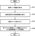
- FIG. 3 is a flowchart showing an operation of associating a feature with gas monitoring image data in the gas monitoring image recording apparatus.
- FIG. 4 is a flowchart showing a search operation in the gas monitoring image recording device.
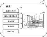
- FIG. 5 is a diagram showing a search top screen displayed on the gas monitoring image recording device.
- FIG. 6 is a diagram showing a gas cloud size search screen displayed on the gas monitoring image recording apparatus.
- FIG. 7 is a view showing a leak position search screen displayed on the gas monitoring image recording apparatus.
- FIG. 8 is a diagram showing a size search result screen for displaying a search result with a gas cloud size displayed on the gas monitoring image recording apparatus.
- FIG. 9 is a diagram showing a position search result screen that displays a search result at a leak position displayed on the gas monitoring image recording device.
- the control processing unit 3 functionally includes a control unit 31, a leakage candidate area extraction unit 32, a feature extraction unit 33, a storage processing unit 34, and a search processing unit 35.
- a plurality of gas monitoring image data is obtained by the image obtaining unit 1, and the obtained plurality of gas monitoring image data is given a file name in the gas monitoring image storage unit 21 of the storage unit 2. Shall be stored.
- the gas monitoring image recording device D in FIG. A plurality of gas monitoring image data stored in the storage unit 21 is extracted in chronological order, and a process of extracting a leakage candidate area based on the extracted gas monitoring image data is executed (S11).
- the control processing unit 3 determines whether or not the leakage candidate area has been extracted in the processing S11 (S12). As a result of this determination, when the leakage candidate area has not been extracted (No), the gas monitoring image recording apparatus D next executes the processing S15, while when the leakage candidate area has been extracted (Yes). Next, the gas monitoring image recording apparatus D sequentially executes the processing of steps S13, S14, and S15.
- the gas monitoring image recording device D extracts a predetermined feature by the feature extracting unit 33 of the control processing unit 3.
- the feature extraction unit 33 determines the leakage position, gas type, and leakage scale (gas cloud size, concentration thickness product, and appearance time) based on the leakage candidate region extracted by the leakage candidate region extraction unit 32, respectively. Extract as
- the gas monitoring image recording device D uses the storage processing unit 34 of the control processing unit 3 to extract the feature extracted by the feature extraction unit 33 in process S13 in the leakage candidate region extraction unit in process S11. 32, the leakage candidate area is stored in the characteristic information storage unit 22 of the storage unit 2 in association with the extracted gas monitoring image data.
- the gas monitoring image recording apparatus D determines whether or not the control processing unit 3 has finished the processing for all the gas monitoring image data stored in the gas monitoring image storage unit 21 of the storage unit 2. Is determined. As a result of this determination, if all the processes have been completed (Yes), the gas monitoring image recording apparatus D ends this process, while if all the processes have not been completed (No), , The gas monitoring image recording device D returns the process to the process S11.
- the gas monitoring image recording apparatus D associates a feature with the gas monitoring image data from which the leakage candidate area has been extracted.
- each process is performed on a plurality of pieces of gas monitoring image data previously acquired by the image acquisition unit 1 and stored in the gas monitoring image storage unit 21 of the storage unit 2.
- Each process may be performed on the gas monitoring image data immediately after the acquisition while acquiring the data.
- the gas monitoring image recording device D displays a search top screen on the display unit 5 by the search processing unit 35 of the control processing unit 3 ( S21).
- the search top screen is a screen for selecting a search item to be searched and inputting the searched search item to the gas monitoring image recording apparatus D.
- a search top screen 71 includes, for example, a “leak gas size” button 711, a “leak gas concentration thickness product” button 712, a “leak time” button 713, and a “leak position” as shown in FIG.
- a button 714, a “leakage gas type” button 715, and a monitoring target image display area 716 for displaying an image of the monitoring target area are provided.
- the “leakage gas size” button 711 is a button for selecting the gas cloud size of the leaked gas as a search item and inputting it to the gas monitoring image recording apparatus D.
- the “leak gas concentration thickness product” button 712 is a button for selecting the leak gas concentration thickness product as a search item and inputting it to the gas monitoring image recording apparatus D.
- the “leakage time” button 713 is a button for selecting the appearance time of the leaked gas as a search item and inputting it to the gas monitoring image recording device D.
- the “leak position” button 714 is a button for selecting a leak position of a leak gas as a search item and inputting the selected position to the gas monitoring image recording apparatus D.
- the “leak gas type” button 715 is a button for selecting a gas type of the leak gas as a search item and inputting the gas type to the gas monitoring image recording apparatus D.
- the user performs an input operation to select a search item on the search top screen.
- the gas monitoring image recording apparatus D causes the search processing unit 35 to display a search screen for each search item on the display unit 5 (S22).
- the search processing unit 35 causes the search top screen 71
- the display unit 5 displays a gas cloud size search screen for receiving a gas cloud size search key from.
- the search screen 72 for the gas cloud size includes a search item name display area 721 for displaying a search item name such as “leakage gas size” and a gas cloud size (search gas cloud) to be searched.
- the search key input units 722 to 725 for inputting the size (size) as a search key to the gas monitoring image recording apparatus D, and a monitoring target image display area 726 similar to the monitoring target image display area 716 are provided.
- the search key input units 722 to 725 input first to third search key input units 722 to 724 in which the search gas cloud size is predetermined, and the search gas cloud size by an arbitrary numerical value.
- a fourth search key input unit 725 that can be used.
- the first search key input unit 722 is a button for inputting a range of 40 m 2 or more as a search gas cloud size to the gas monitoring image recording apparatus D.
- the first search key input unit 722 is displayed with a “rank A 40 m 2 or more” button.
- the second search key input unit 723 is a button for inputting a range larger than 10 m 2 and smaller than 40 m 2 as a search gas cloud size to the gas monitoring image recording apparatus D.
- the third search key input unit 724 is a button for inputting a range of 10 m 2 or less as a search gas cloud size to the gas monitoring image recording device D.
- the third search key input unit 724 is displayed with a “rank C 10 m 2 or less” button.
- the fourth search key input unit 725 is a numerical value input box for inputting a numerical value to the gas monitoring image recording device D.
- the search processing unit 35 displays a concentration thickness product search screen for receiving a concentration thickness product search key from the search top screen 71 on the display unit 5.
- the search screen for the density / thickness product includes a search item name display area for displaying a search item name such as “density / thickness product” and a gas monitoring image recording apparatus using the density / thickness product to be searched (search density / thickness product) as a search key.
- the search key input unit is, for example, a numerical value input box for inputting a numerical value to the gas monitoring image recording device D.
- the search processing unit 35 displays an appearance time search screen for receiving an appearance time search key from the search top screen 71 on the display unit 5.
- a search item name display area for displaying a search item name such as "leakage time” and an appearance time to be searched (search appearance time) are input to the gas monitoring image recording apparatus D as search keys.
- the search key input unit is, for example, a numerical value input box for inputting a numerical value to the gas monitoring image recording device D.
- the search processing unit 35 displays a leak position search screen for receiving a leak position search key from the search top screen 71 on the display unit 5.
- a search item name display area 731 for displaying a search item name such as “leakage position” and a position to be searched (search position) are used as search keys.
- a search key input unit 732 (732-1 to 732-4) for inputting to the gas monitoring image recording device D is provided.
- the search key input unit 732 includes an area displaying the image of the monitoring target area so that the user can specify and input a search position while referring to the image of the monitoring target area. .
- the search position is transmitted to the gas monitoring image recording apparatus D.
- a search key may be input to the gas monitoring image recording device D in an area to be searched (search area). More specifically, as shown in FIG. 7, the search key input unit 732 includes first to fourth search key input units 732-1 to 732-4 obtained by dividing an area in which the image of the monitoring target area is displayed into four parts. It is provided with.
- the first search key input unit 732-1 is a button for inputting the upper left half of the monitoring target area to the gas monitoring image recording apparatus D as a search area.
- the second search key input section 732-2 is a button for inputting the upper right half of the monitoring target area to the gas monitoring image recording device D as a search area.
- the third search key input section 732-3 is a button for inputting the lower left half of the monitoring target area to the gas monitoring image recording apparatus D as a search area.
- the fourth search key input unit 732-4 is a button for inputting the lower right half of the monitoring target area to the gas monitoring image recording device D as a search area.
- the search area may be input in the rectangle by designating two vertices of the rectangle on the image of the monitoring target area.
- the search processing unit 35 displays a gas type search screen for receiving a gas type search key from the search top screen 71 on the display unit 5.
- the search screen for the gas type includes a search item name display area for displaying a search item name such as "leakage gas type” and a gas type to be searched (search gas type) input to the gas monitoring image recording apparatus D as a search key.
- a search key input unit is, for example, a text input box for inputting text to the gas monitoring image recording device D.
- the gas monitoring image recording apparatus D causes the search processing unit 35 to From the plurality of features stored in the feature information storage unit 22, a feature corresponding to the search key received by the input unit 4 is searched, and gas monitoring image data associated with the searched feature is extracted and displayed on the display unit. 5 (S24), and the process ends.
- the search process is performed in the process S24.
- the unit 35 selects (retrieves) feature information having a gas cloud size of 10 m 2 or less from a plurality of feature information stored in the feature information storage unit 22, and selects a gas associated with the selected feature.
- the monitoring image data is extracted from the gas monitoring image storage unit 21, and the gas monitoring image of the extracted gas monitoring image data is displayed on the display unit 5. For example, as shown in FIG.
- the gas monitoring image of the extracted gas monitoring image data is displayed on the display unit 5 on a size search result screen 81 that displays a search result in a gas cloud size.
- the size search result screen 81 includes a screen title area 811 for displaying a screen title such as “search result of rank C” and a search result area 812 for displaying a search result.
- three first to third gas monitoring image data are searched in the process S24, and the search result area 812 displays the gas monitoring image (for example, the first gas monitoring image) of the first gas monitoring image data.
- a first search result area 812-1 for displaying a gas monitoring image from which a leakage candidate area has been extracted from the data (in the case of a plurality of gas monitoring images, one of the gas monitoring images or a moving image);
- a second search result area 812-2 for displaying the gas monitoring image of the gas monitoring image data and a third search result area 812-3 for displaying the gas monitoring image of the third gas monitoring image data are provided.
- each occurrence time of gas leakage is also displayed in each search result area 812-1 to 812-3.
- the search processing unit 35 stores the feature information in the process S24. From among the plurality of pieces of feature information stored in the unit 22, feature information whose leakage position is within the upper left half area of the gas monitoring image is selected (searched), and the gas monitoring information associated with the selected feature information is selected.
- the image data is extracted from the gas monitoring image storage unit 21, and the gas monitoring image of the extracted gas monitoring image data is displayed on the display unit 5. For example, as shown in FIG. 9, the gas monitoring image of the extracted gas monitoring image data is displayed on the display unit 5 on a position search result screen 82 that displays a search result at the leak position.
- the position search result screen 82 includes a screen title area 821 that displays the title of the screen, such as “A zone search result”, and a search result area 822 that displays the search result.
- the search result area 822 stores the gas monitoring image (for example, the first gas monitoring image) of the first gas monitoring image data.
- a first search result area 822-1 for displaying a gas monitoring image from which a leakage candidate area has been extracted from the data (in the case of a plurality of gas monitoring images, one of the gas monitoring images or a moving image);
- a second search result area 822-2 for displaying a gas monitoring image of the gas monitoring image data.
- each occurrence time of gas leakage is also displayed in each search result area 822-1 and 822-2. Further, in the example shown in FIG. 9, in each of the search result areas 822-1 and 822-2, the leak positions PS-1 and PS-2 based on the selected characteristic information are superimposed on the gas monitoring image with crosses. Is displayed.
- the search result is displayed on the display unit 5 by displaying the gas monitoring image of the gas monitoring image data, but may be displayed on the display unit 5 in a file name list of the gas monitoring image data. good. Further, as described above, since the file name is given at the generation time (acquisition time) of the gas monitoring image data, the generation time (acquisition time) may be displayed as shown in FIGS. If the file name is not given at the generation time (acquisition time) of the gas monitoring image data, the generation time (acquisition time) of the gas monitoring image data is stored in the storage unit to display the generation time (acquisition time). 2 may be stored.
- the gas monitoring image recording apparatus D As described above, the gas monitoring image recording apparatus D according to the present embodiment and the gas monitoring image recording method and the gas monitoring image recording program mounted on the gas monitoring image recording apparatus D are based on gas monitoring image data including a plurality of time-series images.
- the feature is extracted, and the extracted feature is stored in the storage unit 2 in association with the gas monitoring image data from which the leakage candidate area is extracted.
- the gas monitoring image recording device D, the gas monitoring image recording method, and the gas monitoring image recording program can use the above features as clues, so that the target image data can be more easily searched.
- the gas monitoring image recording device D the gas monitoring image recording method, and the gas monitoring image recording program that extract the leak position as one of the features.
- Such a gas monitoring image recording device D, a gas monitoring image recording method, and a gas monitoring image recording program can search for target image data based on a leak position. It is possible to grasp the leak tendency for each position or for each area. According to the leak tendency, it is also possible to determine a monitoring strengthening point, repair gas equipment, and plan a replacement time.
- the gas monitoring image recording device D the gas monitoring image recording method, and the gas monitoring image recording program that extract the leakage scale as one of the features. Since such a gas monitoring image recording device D, a gas monitoring image recording method, and a gas monitoring image recording program can search for target image data based on a leak size, a leak tendency is grasped for each leak size. It becomes possible. According to the leak tendency, it is also possible to determine a monitoring strengthening point, repair gas equipment, and plan a replacement time.
- the gas monitoring image recording device D, the gas monitoring image recording method, and the gas monitoring image recording program can search for target image data with a search key.
- a gas monitoring image recording device D a gas monitoring image recording method, and a gas monitoring image recording program that can search for target image data using a search position or a search area as the search key.
- a gas monitoring image recording device D, a gas monitoring image recording method, and a gas monitoring image recording program can grasp a leak tendency for each position or each region in a monitoring target region for monitoring gas leakage. Depending on the leak tendency, it is possible to determine the monitoring strengthening point, repair the gas equipment, and plan the replacement time.
- the gas monitoring image recording device D, the gas monitoring image recording method, and the gas monitoring image recording program display the monitoring target area image on the display unit 5. You can specify the search area.
- the gas monitoring image recording device D, the gas monitoring image recording method, and the gas monitoring image recording program can display the gas monitoring image data and the leak position on the display unit 5, and visually recognize the gas facility that has caused the gas leak.
- a gas monitoring image recording device D a gas monitoring image recording method, and a gas monitoring image recording program capable of searching for target image data using a search gas type as the search key.
- a gas monitoring image recording device D, a gas monitoring image recording method, and a gas monitoring image recording program can grasp a leak tendency for each gas type, determine a monitoring strengthening point and repair gas equipment according to the leak tendency. And the exchange time can be planned.
- the gas monitoring image recording device D the gas monitoring image recording method, and the gas monitoring image recording program that can search for the target image data using the search leak size as the search key.
- Such a gas monitoring image recording device D, a gas monitoring image recording method, and a gas monitoring image recording program can grasp a leak tendency for each leak scale, determine a monitoring strengthening point and repair gas equipment according to the leak tendency. And the exchange time can be planned.
- a gas monitoring image recording device includes a storage unit that stores predetermined data, an image acquisition unit that acquires gas monitoring image data including a plurality of time-series images used for monitoring gas leakage, Based on the gas monitoring image data acquired by the image acquisition unit, a leakage candidate region extraction unit that extracts a leakage candidate region that is a candidate for gas leakage, and when a leakage candidate region is extracted by the leakage candidate region extraction unit, A feature extraction unit for extracting a predetermined feature related to the gas leak, and a feature extracted by the feature extraction unit stored in the storage unit in association with the gas monitoring image data from which the leak candidate region is extracted by the leak candidate region extraction unit. And a storage processing unit.
- the image acquisition unit is an infrared camera that generates the gas monitoring image data.
- the image acquisition unit is a communication unit that performs communication, and receives and acquires the gas monitoring image data from an infrared camera that generates the gas monitoring image data.
- the image acquisition unit is a communication unit that performs communication, and receives and acquires the gas monitoring image data from a server device that stores and provides the gas monitoring image data. I do.
- the image acquisition unit is an interface unit that exchanges data with an external device, and reads and acquires the gas monitoring image data from a storage device that stores the gas monitoring image data. I do.
- the image acquisition unit is a drive device that reads data from a recording medium, and reads and acquires the gas monitoring image data from a storage medium that stores the gas monitoring image data.
- the storage processing unit stores the electronic file containing the features extracted by the feature extraction unit and the gas monitoring image data obtained by extracting the leakage candidate area by the leakage candidate area extraction unit. And stored in the storage unit.
- the gas monitoring image data from which the leakage candidate area is extracted by the leakage candidate area extracting unit is a predetermined time including an image from which the leakage candidate area is extracted by the leakage candidate area extracting unit.
- the storage processing unit stores the feature extracted by the feature extraction unit in a file name of the image data in an electronic file.
- the gas monitoring image data from which the leakage candidate area is extracted by the leakage candidate area extracting unit is a predetermined time including an image from which the leakage candidate area is extracted by the leakage candidate area extracting unit.
- the storage processing unit stores the features extracted by the feature extraction unit in an electronic file of the image data.
- the electronic file of the image data is an mp4 electronic file.
- Such a gas monitoring image recording apparatus when extracting a leakage candidate area based on gas monitoring image data composed of a plurality of time-series images, extracts the feature, and extracts the extracted feature into the leakage candidate area. Is stored in the storage unit in association with the extracted gas monitoring image data. For this reason, the gas monitoring image recording apparatus can use the feature as a clue, so that the target image data can be more easily searched.
- the feature extraction unit extracts a leak position as one of the features based on the leak candidate region.
- a gas monitoring image recording device that extracts a leak position as one of the features.
- Such a gas monitoring image recording apparatus can search for target image data based on a leak position. Therefore, in a monitoring target area for monitoring a gas leak, a leak tendency is detected for each position or for each area. Can be grasped. According to the leak tendency, it is also possible to determine a monitoring strengthening point, repair gas equipment, and plan a replacement time.
- position / shape information indicating an arrangement position and a shape of a gas facility disposed in a monitoring target area for monitoring gas leakage
- a gas information storage unit that stores gas type information representing a gas type of the gas, wherein the feature extraction unit extracts a leakage position based on the leakage candidate area, and stores the extracted leakage position and the gas information storage.
- a gas facility corresponding to the extracted leak position is extracted based on the position and shape information stored in the section, and the gas facility is extracted based on the extracted facility and gas type information stored in the gas information storage section.
- a gas type corresponding to the gas equipment is extracted as another one of the above-mentioned features.
- a gas monitoring image recording device that extracts a gas type as one of the features. Since such a gas monitoring image recording apparatus can search for target image data based on a gas type, it is possible to grasp a leak tendency for each gas type. According to the leak tendency, it is also possible to determine a monitoring strengthening point, repair gas equipment, and plan a replacement time.
- the feature extracting unit determines at least one of a gas cloud size, a concentration thickness product, and an appearance time in the leaked gas based on the leak candidate area.
- the leakage scale including the leakage is extracted as another one of the features.
- a gas monitoring image recording device that extracts the leakage scale as one of the features. Since such a gas monitoring image recording apparatus can search for target image data based on the leak size, it is possible to grasp the leak tendency for each leak size. According to the leak tendency, it is also possible to determine a monitoring strengthening point, repair gas equipment, and plan a replacement time.
- a display unit that displays an image, a search key input unit that receives a predetermined feature as a search key, and a leak candidate area is extracted by the leak candidate area extracting unit. From among the plurality of features stored in the storage unit in association with the obtained gas monitoring image data, a feature corresponding to the search key received by the search key input unit is searched, and the feature is associated with the searched feature.
- a search processing unit that extracts the gas monitoring image data from which the leakage candidate area is extracted by the leakage candidate area extracting unit and displays the data on the display unit.
- Such a gas monitoring image recording apparatus can search for target image data using a search key.
- the search key input unit receives a search position or a search area of a leak position to be searched as the search key.
- the display unit displays a monitoring target region image of a monitoring target region for monitoring gas leakage
- the search key input unit is displayed on the display unit.
- a search position or a search area is specified as the search key.
- Such a gas monitoring image recording device can designate a search position or a search area as a search key while referring to the monitoring target area image displayed on the display unit.
- the search processing unit superimposes the leak position as the searched feature on the extracted gas monitoring image data, and obtains the extracted gas monitoring image data. Is displayed on the display unit.
- Such a gas monitoring image recording device can display gas monitoring image data and a leak position on a display unit, and can visually recognize a gas facility that has caused a gas leak.
- the search key input unit receives a search gas type of a gas type to be searched as the search key.
- a gas monitoring image recording apparatus capable of searching for target image data using a search gas type as the search key.
- a gas monitoring image recording apparatus can grasp a leak tendency for each gas type, and can determine a monitoring strengthening point, and plan a repair or replacement time of a gas facility according to the leak tendency.
- the search key input unit receives a search leak size of a leak size to be searched as the search key.
- a gas monitoring image recording apparatus capable of searching for target image data using a search leak size as the search key.
- a gas monitoring image recording device can grasp a leak tendency for each leak scale, and can determine a monitoring strengthening point, and plan a repair or replacement time of a gas facility according to the leak tendency.
- a gas monitoring image recording method includes an image obtaining step of obtaining gas monitoring image data composed of a plurality of time-series images used for monitoring a gas leak; A leak candidate area extracting step of extracting a leak candidate area that is a candidate for gas leak based on the obtained gas monitoring image data, and, when the leak candidate area is extracted in the leak candidate area extracting step, a predetermined A feature extraction step of extracting a feature, and a storage processing step of storing the feature extracted in the feature extraction step in a storage unit in association with the gas monitoring image data from which the leakage candidate area has been extracted in the leakage candidate area extraction step. .
- a gas monitoring image recording program includes: a computer having an image obtaining step of obtaining gas monitoring image data composed of a plurality of time-series images used for monitoring a gas leak; A leak candidate area extracting step of extracting a leak candidate area that is a candidate for gas leak based on the gas monitoring image data obtained in the step, and, when the leak candidate area is extracted in the leak candidate area extracting step, the gas leak is detected.
- Such a gas monitoring image recording method and a gas monitoring image recording program when a leakage candidate area is extracted based on gas monitoring image data composed of a plurality of time-series images, extract the feature, and extract the extracted feature. Is stored in the storage unit in association with the gas monitoring image data from which the leakage candidate area has been extracted. Therefore, the gas monitoring image recording method and the gas monitoring image recording program can use the above features as clues, and thus can easily search for target image data.
- a gas monitoring image recording device a gas monitoring image recording method, and a gas monitoring image recording program for recording a gas monitoring image used for monitoring a gas leak.
Landscapes
- Engineering & Computer Science (AREA)
- Physics & Mathematics (AREA)
- General Physics & Mathematics (AREA)
- Theoretical Computer Science (AREA)
- Computer Vision & Pattern Recognition (AREA)
- Multimedia (AREA)
- Quality & Reliability (AREA)
- Library & Information Science (AREA)
- Geometry (AREA)
- Databases & Information Systems (AREA)
- General Engineering & Computer Science (AREA)
- Data Mining & Analysis (AREA)
- Examining Or Testing Airtightness (AREA)
- Information Retrieval, Db Structures And Fs Structures Therefor (AREA)
- Image Analysis (AREA)
Abstract
本発明のガス監視画像記録装置、該方法および該プログラムは、ガス漏れの監視に利用される時系列な複数の画像から成るガス監視画像データを取得し、この取得したガス監視画像データに基づいて、ガス漏れの候補となる漏洩候補領域を抽出し、前記漏洩候補領域を抽出した場合に、前記ガス漏れに関する所定の特徴を抽出し、この抽出した特徴を、前記漏洩候補領域を抽出したガス監視画像データに関連付けて記憶部に記憶する。
Description
本発明は、ガス漏れの監視に利用されるガス監視画像を記録するガス監視画像記録装置、ガス監視画像記録方法およびガス監視画像記録プログラムに関する。
例えば、可燃性ガス、毒性ガスおよび有機溶剤の蒸気等のガスが配管やタンク等から漏洩した場合、早期に対処する必要がある。このため、漏洩ガス等のガスを求める装置が研究、開発されている。このような装置の1つとして、例えば、特許文献1に開示されたガス漏れ検出装置がある。
この特許文献1に開示されたガス漏れ検出装置は、検査対象領域におけるガス漏れを検出するガス漏れ検出装置において、検査対象領域を撮影する赤外線カメラと、赤外線カメラにより撮影された赤外線画像を処理する画像処理部と、画像処理部の処理結果に基づいてガス漏れを判断するガス漏れ判断部と、を有し、画像処理部は、時系列に並べられた複数の赤外線画像からガス漏れによる動的なゆらぎを抽出するゆらぎ抽出部を有し、ガス漏れ判断部は、ゆらぎ抽出部により動的なゆらぎが抽出された場合、ガス漏れが発生していると判断する。
上記特許文献1に開示されたガス漏れ検出装置のような監視カメラでガス漏れを監視する場合、監視で得られた画像データは、保存されることが一般的である。このような保存された画像データは、ガス漏れが発生した場合にその状況を表す資料や、ガスの施設に対する保全業務の資料等として活用できる。しかしながら、前記画像データは、通常、毎日連続で得られ保存されるので、膨大となるため、前記膨大な画像データの中から、目的の資料(画像データ)を探すことが難しい。
本発明は、上述の事情に鑑みて為された発明であり、その目的は、より容易に目的の画像データを探すことができるガス監視画像記録装置、ガス監視画像記録方法およびガス監視画像記録プログラムを提供することである。
上述した目的を実現するために、本発明の一側面を反映したガス監視画像記録装置、ガス監視画像記録方法およびガス監視画像記録プログラムは、ガス漏れの監視に利用される時系列な複数の画像から成るガス監視画像データを取得し、この取得したガス監視画像データに基づいて、ガス漏れの候補となる漏洩候補領域を抽出し、前記漏洩候補領域を抽出した場合に、前記ガス漏れに関する所定の特徴を抽出し、この抽出した特徴を、前記漏洩候補領域を抽出したガス監視画像データに関連付けて記憶部に記憶する。
発明の1または複数の実施形態により与えられる利点および特徴は、以下に与えられる詳細な説明および添付図面から十分に理解される。これら詳細な説明及び添付図面は、例としてのみ与えられるものであり本発明の限定の定義として意図されるものではない。
以下、図面を参照して、本発明の1または複数の実施形態が説明される。しかしながら、発明の範囲は、開示された実施形態に限定されない。なお、各図において同一の符号を付した構成は、同一の構成であることを示し、適宜、その説明を省略する。本明細書において、総称する場合には添え字を省略した参照符号で示し、個別の構成を指す場合には添え字を付した参照符号で示す。
図1は、実施形態におけるガス監視画像記録装置の構成を示すブロック図である。図2は、前記ガス監視画像記録装置における特徴を説明するための図である。
実施形態におけるガス監視画像記録装置は、ガス漏れの監視に利用されるガス監視画像の画像データ(ガス監視画像データ)を検索可能に記憶部に記憶する装置であり、例えば、図1に示すように、画像取得部1と、記憶部2と、制御処理部3と、入力部4と、表示部5と、インターフェース部(IF部)6とを備える。
画像取得部1は、制御処理部3に接続され、制御処理部3の制御に従って、ガス漏れの監視に利用される、時系列な複数の画像から成るガス監視画像データを取得する装置である。前記ガス監視画像データは、本実施形態では、赤外線画像からガス漏れを検出するので、ガス漏れを監視する監視対象領域を被写体として赤外線カメラで撮像することによって生成された、時系列な複数の赤外線画像から成るデータである。本実施形態では、前記ガス監視画像データは、所定の時間長の動画データであり、監視時間に応じて複数備える。例えば、10秒ごとにガス監視画像データが生成されると、24時間では、ガス監視画像データは、6×60×24=8640個となり、1年間では、ガス監視画像データは、8640×365=3153600個となる。また例えば、20秒ごとにガス監視画像データが生成されると、24時間では、ガス監視画像データは、3×60×24=4320個となり、1年間では、ガス監視画像データは、4320×365=1576800個となる。これら複数のガス監視画像データに対し、個々に識別可能に任意のファイル名が付される。例えば、ガス監視画像データの生成時刻(取得時刻)でファイル名が付される。
画像取得部1は、例えば、このようなガス監視画像データを生成する赤外線カメラであって良い。また例えば、画像取得部1は、例えばネットワークカード等の、通信を行う通信部であり、前記ガス監視画像データを生成する赤外線カメラからネットワークを介して前記ガス監視画像データを受信して取得する。また例えば、画像取得部1は、通信を行う通信部であり、前記ガス監視画像データを記憶して提供するサーバ装置からネットワークを介して前記ガス監視画像データを受信して取得する。また例えば、画像取得部1は、例えばUSB(Universal Serial Bus)規格で外部機器とデータを交換するインターフェース部であり、前記ガス監視画像データを記憶する、例えばUSBメモリ等の記憶装置から前記ガス監視画像データを読み込んで取得する。また例えば、画像取得部1は、例えばCD-ROM等の記録媒体からデータを読み込むドライブ装置であり、前記ガス監視画像データを記憶する前記記憶媒体から前記ガス監視画像データを読み込んで取得する。
画像取得部1は、取得したガス監視画像データを制御処理部3へ出力し、制御処理部3は、画像取得部1で取得したガス監視画像データを記憶部2に記憶する。
入力部4は、制御処理部3に接続され、例えば、ガス監視画像データに対する所定の特徴を関連付ける関連付け処理の開始を指示するコマンドや、検索の開始を指示するコマンド等の各種コマンド、および、例えば監視対象領域の名称等の前記関連付け処理を実施する上で必要な各種データや、検索キー等の検索する上で必要な各種データをガス監視画像記録装置Dに入力する機器であり、例えば、キーボードやマウス等である。入力部4は、所定の特徴を検索キーとして受け付ける検索キー入力部の一例に相当する。表示部5は、制御処理部3に接続され、制御処理部3の制御に従って、入力部4から入力されたコマンドやデータ、および、ガス監視画像記録装置Dによって検索されたガス監視画像データの画像を出力する機器であり、例えばCRTディスプレイ、液晶ディスプレイおよび有機ELディスプレイ等の表示装置である。
なお、入力部4および表示部5からタッチパネルが構成されてもよい。このタッチパネルを構成する場合において、入力部4は、例えば抵抗膜方式や静電容量方式等の操作位置を検出して入力する位置入力装置である。このタッチパネルでは、表示部5の表示面上に位置入力装置が設けられ、表示部5に入力可能な1または複数の入力内容の候補が表示され、ユーザが、入力したい入力内容を表示した表示位置を触れると、位置入力装置によってその位置が検出され、検出された位置に表示された表示内容がユーザの操作入力内容としてガス監視画像記録装置Dに入力される。このようなタッチパネルでは、ユーザは、入力操作を直感的に理解し易いので、ユーザにとって取り扱い易いガス監視画像記録装置Dが提供される。
IF部6は、制御処理部3に接続され、制御処理部3の制御に従って、外部機器との間でデータの入出力を行う回路であり、例えば、シリアル通信方式であるRS-232Cのインターフェース回路、Bluetooth(登録商標)規格を用いたインターフェース回路、IrDA(Infrared Data Association)規格等の赤外線通信を行うインターフェース回路、および、USB(Universal Serial Bus)規格を用いたインターフェース回路等である。なお、画像取得部1が上述で例示したように前記通信部である場合には、必要ではないが、IF部6は、外部機器との間で通信を行う回路であり、例えば、データ通信カードや、IEEE802.11規格等に従った通信インターフェース回路等であっても良い。
記憶部2は、制御処理部3に接続され、制御処理部3の制御に従って、各種の所定のプログラムおよび各種の所定のデータを記憶する回路である。
前記各種の所定のプログラムには、制御プログラム、漏洩候補領域抽出プログラム、特徴抽出プログラム、記憶処理プログラムおよび検索処理プログラム等の制御処理プログラムが含まれる。前記制御プログラムは、ガス監視画像記録装置Dの各部1、2、4~6を当該各部の機能に応じてそれぞれ制御するプログラムである。前記漏洩候補領域抽出プログラムは、画像取得部1で取得したガス監視画像データに基づいて、ガス漏れの候補となる漏洩候補領域を抽出するプログラムである。前記特徴抽出プログラムは、前記漏洩候補領域抽出プログラムで漏洩候補領域を抽出した場合に、前記ガス漏れに関する所定の特徴を抽出するプログラムである。前記記憶処理プログラムは、前記特徴抽出プログラムで抽出した特徴を、前記漏洩候補領域抽出プログラムで漏洩候補領域を抽出したガス監視画像データに関連付けて記憶部2に記憶するプログラムである。前記検索処理プログラムは、前記漏洩候補領域抽出プログラムで漏洩候補領域を抽出したガス監視画像データに関連付けて記憶部2に記憶された複数の特徴の中から、入力部4で受け付けた検索キーに対応する特徴を検索し、前記検索した特徴に関連づけられている、前記漏洩候補領域抽出プログラムで漏洩候補領域を抽出したガス監視画像データを取り出して表示部5に表示するプログラムである。
前記各種の所定のデータには、例えば画像取得部1で取得した複数のガス監視画像データや、特徴情報や、ガス情報等の、各プログラムを実行する上で必要なデータ等が含まれる。
記憶部2は、例えば不揮発性の記憶素子であるROM(Read Only Memory)や書き換え可能な不揮発性の記憶素子であるEEPROM(Electrically Erasable Programmable Read Only Memory)等を備える。記憶部2は、前記所定のプログラムの実行中に生じるデータ等を記憶するいわゆる制御処理部3のワーキングメモリとなるRAM(Random Access Memory)等を含む。記憶部2は、比較的大容量のデータを記憶できるハードディスク装置を備えても良い。そして、記憶部2は、複数のガス監視画像データ、特徴情報およびガス情報係数情報それぞれを記憶するために、ガス監視画像記憶部21、特徴情報記憶部22およびガス情報記憶部23それぞれを機能的に備える。
ガス監視画像記憶部21は、画像取得部1で取得した複数のガス監視画像データを、所定のファイル名を付して記憶するものである。
特徴情報記憶部22は、前記記憶処理プログラムでガス監視画像データに関連付けられた特徴を表す特徴情報を記憶するものである。前記特徴については後述する。例えば、特徴情報記憶部22は、特徴情報および前記特徴情報に関連付けられるガス監視画像データのファイル名を収容した電子ファイルを、個々に識別可能に任意のファイル名を付して記憶する。また例えば、特徴情報記憶部22は、特徴情報を収容した電子ファイルを、前記特徴情報に関連付けられるガス監視画像データのファイル名と拡張子を除き同じファイル名を付して記憶する。また例えば、特徴情報記憶部22は、特徴情報を、前記特徴情報に関連付けられるガス監視画像データのファイル名に組み込んで収容する。この場合、特徴情報記憶部22は、ガス監視画像記憶部21と兼用される。また例えば、特徴情報記憶部22は、特徴情報を、前記特徴情報に関連付けられるガス監視画像データの電子ファイルに組み込んで収容する。このようなメタデータ(本実施形態では特徴情報)を収容できる動画データの電子ファイルは、例えば、mp4形式の電子ファイルである。この場合も、特徴情報記憶部22は、ガス監視画像記憶部21と兼用される。なお、特徴情報がガス監視画像データのファイル名に組み込まれて収容される場合や、特徴情報がガス監視画像データの電子ファイルに組み込まれて収容される場合では、前記特徴情報は、例えば符号化されることで、データ量が圧縮されることが好ましい。この場合では、前記特徴情報と符号との対応関係が記憶部2に記憶される。
ガス情報記憶部23は、前記特徴を抽出する上で必要なガスに関するガス情報を記憶するものである。前記ガス情報は、例えば、本実施形態では、ガス漏れを監視する監視対象領域に配設されているガス設備(ガス施設)の配設位置およびその形状を表す位置形状情報、および、前記ガス設備内のガスにおけるガス種を表すガス種情報等である。前記ガス設備(ガス施設)は、例えば、配管、タンクおよびバルブ等である。前記位置形状情報は、例えばガス設備の名称等のガス設備を特定し識別するための識別子(ガス設備ID)と、その位置および形状それぞれとを互いに対応付けてガス情報記憶部23に記憶される。ガス設備の位置および形状のデータ基づいて前記ガス設備の占有領域が求められる。前記位置は、前記監視対象領域に設定された座標系で表された実際の座標値であって良いが、前記監視対象領域を被写体として撮像した画像における画素位置で表されることが好ましい。これによれば、画像から求めた漏洩位置から容易にガス漏れを起こしたガス設備が特定できる。前記ガス種情報は、前記ガス設備IDと、そのガス設備内のガスのガス種(ガスの種類)とを互いに対応付けてガス情報記憶部23に記憶される。
制御処理部3は、ガス監視画像記録装置Dの各部1、2、4~6を当該機能に応じて制御し、ガス漏れの監視に利用されるガス監視画像データを検索可能に記憶部2に記憶するための回路である。より具体的には、制御処理部3は、本実施形態では、前記所定の制御処理プログラムが実行されることによって、制御部31と、漏洩候補領域抽出部32と、特徴抽出部33と、記憶処理部34と、検索処理部35とを機能的に備える。
制御部31は、ガス監視画像記録装置Dの各部1、2、4~6を当該機能に応じて制御し、ガス監視画像記録装置Dの全体制御を司るものである。
漏洩候補領域抽出部32は、画像取得部1で取得したガス監視画像データに基づいて、ガス漏れの候補となる漏洩候補領域を抽出するものである。このような漏洩候補領域の抽出には、例えば特許第5343054号公報(特開2012-058093号公報)に開示された手法や国際公開第2017/073426号に開示された手法や国際公開第2017/073430号に開示された手法等の公知の手法が利用される。
特徴抽出部33は、漏洩候補領域抽出部32で漏洩候補領域を抽出した場合に、ガス漏れに関する所定の特徴を抽出するものである。
前記特徴は、例えば、図2に示すように、ガスが漏れ出している箇所の位置である漏洩位置PSを含み、特徴抽出部33は、漏洩候補領域抽出部32で抽出した漏洩候補領域に基づいて漏洩位置を抽出する。特徴抽出部33は、例えば、時系列で連続的に抽出される漏洩候補領域のうちの最初に抽出された漏洩候補領域の位置(またはその中央位置)を漏洩位置として抽出する。また例えば、特徴抽出部33は、国際公開第2017/073426号に開示された手法で漏洩位置を抽出する。
また例えば、前記特徴は、漏れているガスの種類であるガス種を含み、特徴抽出部33は、漏洩候補領域抽出部32で抽出した漏洩候補領域に基づいて漏洩位置を抽出し、この抽出した漏洩位置およびガス情報記憶部に記憶されている位置形状情報に基づいて前記抽出した漏洩位置に対応するガス設備を抽出し、この抽出した施設およびガス情報記憶部に記憶されているガス種情報に基づいて前記抽出したガス設備に対応するガス種を抽出する。なお、ガス監視画像データを生成した赤外線カメラと監視対象領域との距離や前記赤外線カメラの画角等は、既知であるとする。より具体的には、本実施形態では、まず、特徴抽出部33は、上述の手法により、漏洩候補領域抽出部32で抽出した漏洩候補領域に基づいて漏洩位置を抽出する。次に、特徴抽出部33は、ガス情報記憶部に記憶されている位置形状情報から、この抽出した漏洩位置に対応するガス設備IDを選定(検索)する。そして、特徴抽出部33は、ガス情報記憶部に記憶されているガス種情報から、この選定したガス設備IDに対応するガス種を選定(検索)する。これによって漏洩ガスのガス種が抽出される。例えば、図2に示すように、漏洩ガスの漏洩位置PSがメタン配管PP2上で抽出されると、メタンがガス種として抽出される。
また例えば、前記特徴は、漏れているガスの規模である漏洩規模を含み、特徴抽出部33は、漏洩候補領域抽出部32で抽出した漏洩候補領域に基づいて漏洩規模を抽出する。前記漏洩規模は、漏洩ガスにおけるガス雲サイズ、濃度厚み積および出現時間のうちの少なくとも1つを含む。特徴抽出部33は、漏洩候補領域抽出部32で抽出した漏洩候補領域のサイズを前記ガス雲サイズとして求める。例えば、図2に示すように、特徴抽出部33は、漏洩候補領域抽出部32で抽出した漏洩候補領域における横方向の長さWxおよび縦方向の長さWyを前記ガス雲サイズとして求める(ガス雲サイズ=Wx×Wy)。特徴抽出部33は、例えば、国際公開第2017/104607号に開示された手法や国際公開第2017/073429号に開示された手法等によって漏洩ガスの濃度厚み積を求める。特徴抽出部33は、時系列で連続的に抽出される漏洩候補領域のうちの最初および最後それぞれに抽出された各漏洩候補領域の各抽出時刻の差から、漏洩ガスの出現時間を求める。
記憶処理部34は、特徴抽出部33で抽出した特徴を、漏洩候補領域抽出部32で漏洩候補領域を抽出したガス監視画像データに関連付けて記憶部2に記憶するものである。
例えば、記憶処理部34は、特徴抽出部33で抽出した特徴を収容した電子ファイルを、漏洩候補領域抽出部32で漏洩候補領域を抽出したガス監視画像データに関連付けて記憶部2の特徴情報記憶部22に記憶する。より具体的には、記憶処理部34は、特徴抽出部33で抽出した特徴を表す特徴情報および前記特徴情報に関連付けられるガス監視画像データのファイル名を収容した電子ファイルを、個々に識別可能に任意のファイル名を付して特徴情報記憶部22に記憶する。あるいは、記憶処理部34は、特徴抽出部33で抽出した特徴を表す特徴情報を収容した電子ファイルを、前記特徴情報に関連付けられるガス監視画像データのファイル名と拡張子を除き同じファイル名を付して特徴情報記憶部22に記憶する。
また例えば、記憶処理部34は、特徴抽出部33で抽出した特徴を表す特徴情報を、前記特徴情報に関連付けられるガス監視画像データのファイル名に組み込む。
また例えば、記憶処理部34は、特徴抽出部33で抽出した特徴を表す特徴情報を、前記特徴情報に関連付けられるガス監視画像データの電子ファイルに組み込む。
検索処理部35は、漏洩候補領域抽出部32で漏洩候補領域を抽出したガス監視画像データに関連付けて記憶部2の特徴情報記憶部22に記憶された複数の特徴の中から、入力部4で受け付けた検索キーに対応する特徴を検索し、この検索した特徴に関連づけられている、漏洩候補領域抽出部32で漏洩候補領域を抽出したガス監視画像データを取り出して表示部5に表示するものである。
例えば、入力部4は、検索すべき漏洩位置の検索位置または検索領域を前記検索キーとして受け付ける。より具体的には、表示部5は、ガス漏れを監視する監視対象領域を被写体として撮像することによって得られた監視対象領域画像を表示し、入力部4は、表示部5に表示された監視対象領域画像で前記検索キーとしての検索位置または検索領域の指定を受け付ける。検索処理部35は、漏洩候補領域抽出部32で漏洩候補領域を抽出したガス監視画像データに関連付けて記憶部2の特徴情報記憶部22に記憶された複数の漏洩位置の中から、入力部4で検索キーとして受け付けた検索位置または検索領域に対応する漏洩位置を検索し、この検索した漏洩位置に関連づけられている、漏洩候補領域抽出部32で漏洩候補領域を抽出したガス監視画像データを取り出して表示部5に表示する。より具体的には、検索処理部35は、前記検索した特徴としての漏洩位置を前記取り出したガス監視画像データに重畳して、前記取り出したガス監視画像データを表示部5に表示する。
また例えば、入力部4は、検索すべきガス種の検索ガス種を前記検索キーとして受け付ける。検索処理部35は、漏洩候補領域抽出部32で漏洩候補領域を抽出したガス監視画像データに関連付けて記憶部2の特徴情報記憶部22に記憶された複数のガス種の中から、入力部4で検索キーとして受け付けた検索ガス種に対応するガス種を検索し、この検索したガス種に関連づけられている、漏洩候補領域抽出部32で漏洩候補領域を抽出したガス監視画像データを取り出して表示部5に表示する。
また例えば、入力部4は、検索すべき漏洩規模の検索漏洩規模を前記検索キーとして受け付ける。前記検索漏洩規模は、漏洩ガスにおけるガス雲サイズ、濃度厚み積および出現時間のうちの少なくとも1つを含む。検索処理部35は、漏洩候補領域抽出部32で漏洩候補領域を抽出したガス監視画像データに関連付けて記憶部2の特徴情報記憶部22に記憶された複数の漏洩規模の中から、入力部4で検索キーとして受け付けた検索漏洩規模に対応する漏洩規模を検索し、この検索した漏洩規模に関連づけられている、漏洩候補領域抽出部32で漏洩候補領域を抽出したガス監視画像データを取り出して表示部5に表示する。より具体的には、前記検索漏洩規模がガス雲サイズである場合には、検索処理部35は、漏洩候補領域抽出部32で漏洩候補領域を抽出したガス監視画像データに関連付けて記憶部2の特徴情報記憶部22に記憶された複数のガス雲サイズの中から、入力部4で検索キーとして受け付けた検索ガス雲サイズに対応するガス雲サイズを検索し、この検索したガス雲サイズに関連づけられている、漏洩候補領域抽出部32で漏洩候補領域を抽出したガス監視画像データを取り出して表示部5に表示する。前記検索漏洩規模が濃度厚み積である場合には、検索処理部35は、漏洩候補領域抽出部32で漏洩候補領域を抽出したガス監視画像データに関連付けて記憶部2の特徴情報記憶部22に記憶された複数の濃度厚み積の中から、入力部4で検索キーとして受け付けた検索濃度厚み積に対応する濃度厚み積を検索し、この検索した濃度厚み積に関連づけられている、漏洩候補領域抽出部32で漏洩候補領域を抽出したガス監視画像データを取り出して表示部5に表示する。前記検索漏洩規模が出現時間である場合には、検索処理部35は、漏洩候補領域抽出部32で漏洩候補領域を抽出したガス監視画像データに関連付けて記憶部2の特徴情報記憶部22に記憶された複数の出現時間の中から、入力部4で検索キーとして受け付けた検索出現時間に対応する出現時間を検索し、この検索した出現時間に関連づけられている、漏洩候補領域抽出部32で漏洩候補領域を抽出したガス監視画像データを取り出して表示部5に表示する。
このようなガス監視画像記録装置Dは、画像取得部1を除き、例えばデスクトップ型やノード型等のコンピュータによって構成可能である。
次に、本実施形態の動作について説明する。図3は、前記ガス監視画像記録装置におけるガス監視画像データに特徴を関連付ける動作を示すフローチャートである。図4は、前記ガス監視画像記録装置における検索の動作を示すフローチャートである。図5は、前記ガス監視画像記録装置に表示される検索トップ画面を示す図である。図6は、前記ガス監視画像記録装置に表示されるガス雲サイズの検索画面を示す図である。図7は、前記ガス監視画像記録装置に表示される漏洩位置の検索画面を示す図である。図8は、前記ガス監視画像記録装置に表示されるガス雲サイズでの検索結果を表示するサイズ検索結果画面を示す図である。図9は、前記ガス監視画像記録装置に表示される漏洩位置での検索結果を表示する位置検索結果画面を示す図である。
このような構成のガス監視画像記録装置Dは、その電源が投入されると、必要な各部の初期化を実行し、その稼働を始める。その制御処理プログラムの実行によって、制御処理部3には、制御部31、漏洩候補領域抽出部32、特徴抽出部33、記憶処理部34および検索処理部35が機能的に構成される。そして、ここでは、複数のガス監視画像データが画像取得部1で取得され、記憶部2のガス監視画像記憶部21には、この取得された複数のガス監視画像データがファイル名を付せられて記憶されているものとする。
ガス監視画像記録装置Dにおけるガス監視画像データに特徴を関連付ける動作では、図3において、ガス監視画像記録装置Dは、制御処理部3の漏洩候補領域抽出部32によって、記憶部2のガス監視画像記憶部21に記憶されている複数のガス監視画像データを時系列順に取り出し、この取り出したガス監視画像データに基づいて漏洩候補領域を抽出する処理を実行する(S11)。
続いて、ガス監視画像記録装置Dは、制御処理部3によって、前記処理S11で漏洩候補領域を抽出したか否かを判定する(S12)。この判定の結果、漏洩候補領域が抽出されていない場合(No)には、ガス監視画像記録装置Dは、次に処理S15を実行し、一方、漏洩候補領域が抽出されている場合(Yes)には、ガス監視画像記録装置Dは、次に処理S13、処理S14および処理S15の各処理を順次に実行する。
この処理S13では、ガス監視画像記録装置Dは、制御処理部3の特徴抽出部33によって、所定の特徴を抽出する。本実施形態では、特徴抽出部33は、漏洩候補領域抽出部32で抽出した漏洩候補領域に基づいて漏洩位置、ガス種および漏洩規模(ガス雲サイズ、濃度厚み積および出現時間)それぞれを前記特徴として抽出する。
続いて、処理S14では、ガス監視画像記録装置Dは、制御処理部3の記憶処理部34によって、前記処理S13で特徴抽出部33によって抽出した前記特徴を、前記処理S11で漏洩候補領域抽出部32によって漏洩候補領域を抽出したガス監視画像データに関連付けて記憶部2の特徴情報記憶部22に記憶する。
そして、処理S15では、ガス監視画像記録装置Dは、制御処理部3によって、記憶部2のガス監視画像記憶部21に記憶されている全てのガス監視画像データに対して処理を終了したか否かを判定する。この判定の結果、全ての処理が終了している場合(Yes)には、ガス監視画像記録装置Dは、本処理を終了し、一方、全ての処理が終了していない場合(No)には、ガス監視画像記録装置Dは、処理を処理S11に戻す。
このような動作によって、ガス監視画像記録装置Dは、漏洩候補領域を抽出したガス監視画像データに特徴を関連付ける。
なお、上述では、予め画像取得部1で取得され記憶部2のガス監視画像記憶部21に記憶された複数のガス監視画像データについて各処理が実行されたが、画像取得部1でガス監視画像データを取得しつつ、取得後直ちにガス監視画像データについて各処理が実行されても良い。
一方、ガス監視画像記録装置Dにおける検索の動作では、図4において、まず、ガス監視画像記録装置Dは、制御処理部3の検索処理部35によって、検索トップ画面を表示部5に表示する(S21)。
前記検索トップ画面は、検索したい検索項目を選択してこの検索した検索項目をガス監視画像記録装置Dに入力するための画面である。このような検索トップ画面71は、例えば、図5に示すように、「漏洩ガスサイズ」ボタン711と、「漏洩ガス濃度厚み積」ボタン712と、「漏洩時間」ボタン713と、「漏洩位置」ボタン714と、「漏洩ガス種」ボタン715と、監視対象領域を撮像した画像を表示する監視対象画像表示領域716とを備える。「漏洩ガスサイズ」ボタン711は、検索項目として漏洩ガスのガス雲サイズを選択してガス監視画像記録装置Dに入力するためボタンである。「漏洩ガス濃度厚み積」ボタン712は、検索項目として漏洩ガスの濃度厚み積を選択してガス監視画像記録装置Dに入力するためボタンである。「漏洩時間」ボタン713は、検索項目として漏洩ガスの出現時間を選択してガス監視画像記録装置Dに入力するためボタンである。「漏洩位置」ボタン714は、検索項目として漏洩ガスの漏洩位置を選択してガス監視画像記録装置Dに入力するためボタンである。「漏洩ガス種」ボタン715は、検索項目として漏洩ガスのガス種を選択してガス監視画像記録装置Dに入力するためボタンである。
ユーザ(検索者)は、検索トップ画面で検索項目を選択する入力操作を行う。検索項目の入力操作を受け付けると、ガス監視画像記録装置Dは、検索処理部35によって、検索項目別の検索画面を表示部5に表示する(S22)。
例えば、ユーザがマウスカーソル727を「漏洩ガスサイズ」ボタン711上に移動させ左ダブルクリックする等の、「漏洩ガスサイズ」ボタン711の入力操作を受け付けると、検索処理部35は、検索トップ画面71からガス雲サイズの検索キーを受け付けるガス雲サイズの検索画面を表示部5に表示する。このガス雲サイズの検索画面72は、例えば、図6に示すように、“漏洩ガスサイズ”のように検索項目名を表示する検索項目名表示領域721と、検索したいガス雲サイズ(検索ガス雲サイズ)を検索キーとしてガス監視画像記録装置Dに入力する検索キー入力部722~725と、監視対象画像表示領域716と同様の監視対象画像表示領域726とを備える。図6に示す例では、検索キー入力部722~725は、検索ガス雲サイズが予め規定されている第1ないし第3検索キー入力部722~724と、検索ガス雲サイズを任意の数値で入力できる第4検索キー入力部725とを備えている。第1検索キー入力部722は、検索ガス雲サイズとして40m2以上の範囲をガス監視画像記録装置Dに入力するためボタンであり、図6では、「ランクA 40m2以上」ボタンで表示されている。第2検索キー入力部723は、検索ガス雲サイズとして10m2より大きく40m2より小さい範囲をガス監視画像記録装置Dに入力するためボタンであり、図6では、「ランクB 10m2<サイズ<40m2」ボタンで表示されている。第3検索キー入力部724は、検索ガス雲サイズとして10m2以下の範囲をガス監視画像記録装置Dに入力するためボタンであり、図6では、「ランクC 10m2以下」ボタンで表示されている。第4検索キー入力部725は、数値をガス監視画像記録装置Dに入力する数値入力ボックスである。
また例えば、「漏洩ガス濃度厚み積」ボタン712の入力操作を受け付けると、検索処理部35は、検索トップ画面71から濃度厚み積の検索キーを受け付ける濃度厚み積の検索画面を表示部5に表示する。この濃度厚み積の検索画面は、“濃度厚み積”のように検索項目名を表示する検索項目名表示領域と、検索したい濃度厚み積(検索濃度厚み積)を検索キーとしてガス監視画像記録装置Dに入力する検索キー入力部とを備える。前記検索キー入力部は、例えば、数値をガス監視画像記録装置Dに入力する数値入力ボックスである。
また例えば、「漏洩時間」ボタン713の入力操作を受け付けると、検索処理部35は、検索トップ画面71から出現時間の検索キーを受け付ける出現時間の検索画面を表示部5に表示する。この出現時間の検索画面は、“漏洩時間”のように検索項目名を表示する検索項目名表示領域と、検索したい出現時間(検索出現時間)を検索キーとしてガス監視画像記録装置Dに入力する検索キー入力部とを備える。前記検索キー入力部は、例えば、数値をガス監視画像記録装置Dに入力する数値入力ボックスである。
また例えば、「漏洩位置」ボタン714の入力操作を受け付けると、検索処理部35は、検索トップ画面71から漏洩位置の検索キーを受け付ける漏洩位置の検索画面を表示部5に表示する。この漏洩位置の検索画面73は、例えば、図7に示すように、“漏洩位置”のように検索項目名を表示する検索項目名表示領域731と、検索したい位置(検索位置)を検索キーとしてガス監視画像記録装置Dに入力する検索キー入力部732(732-1~732-4)とを備える。検索キー入力部732は、本実施形態では、ユーザが監視対象領域の画像を参照しながら検索位置を指定して入力できるように、監視対象領域の画像を表示した領域を備えて構成されている。このような監視対象領域の画像上で検索位置を指定する入力操作(例えば検索位置にマウスカーソルを合わせて左ダブルクリックを行う操作等)を行うことで、検索位置がガス監視画像記録装置Dに入力されてもよいが、本実施形態では、検索したい領域(検索領域)で検索キーがガス監視画像記録装置Dに入力される。より具体的には、検索キー入力部732は、図7に示すように、監視対象領域の画像を表示した領域を4分割した第1ないし第4検索キー入力部732-1~732-4を備えて構成されている。第1検索キー入力部732-1は、監視対象領域の左上半分を検索領域としてガス監視画像記録装置Dに入力するためボタンである。第2検索キー入力部732-2は、監視対象領域の右上半分を検索領域としてガス監視画像記録装置Dに入力するためボタンである。第3検索キー入力部732-3は、監視対象領域の左下半分を検索領域としてガス監視画像記録装置Dに入力するためボタンである。第4検索キー入力部732-4は、監視対象領域の右下半分を検索領域としてガス監視画像記録装置Dに入力するためボタンである。なお、監視対象領域の画像上において、矩形の2頂点を指定することで前記矩形で検索領域が入力されても良い。
また例えば、「漏洩ガス種」ボタン715の入力操作を受け付けると、検索処理部35は、検索トップ画面71からガス種の検索キーを受け付けるガス種の検索画面を表示部5に表示する。このガス種の検索画面は、“漏洩ガス種”のように検索項目名を表示する検索項目名表示領域と、検索したいガス種(検索ガス種)を検索キーとしてガス監視画像記録装置Dに入力する検索キー入力部とを備える。前記検索キー入力部は、例えば、テキストをガス監視画像記録装置Dに入力するテキスト入力ボックスである。
図4に戻って、そして、検索項目別の検索画面を用いて入力部4から検索キーの入力を受け付けると(S23)、ガス監視画像記録装置Dは、検索処理部35によって、記憶部2の特徴情報記憶部22に記憶された複数の特徴の中から、入力部4で受け付けた検索キーに対応する特徴を検索し、この検索した特徴に関連づけられているガス監視画像データを取り出して表示部5に表示し(S24)、本処理を終了する。
例えば、前記処理S23で、図6に示すガス雲サイズの検索画面72における、第3検索キー入力部724の「ランクC 10m2以下」ボタンの入力操作を受け付けると、前記処理S24で、検索処理部35は、特徴情報記憶部22に記憶されている複数の特徴情報の中から、ガス雲サイズが10m2以下である特徴情報を選定(検索)し、この選定した特徴に関連付けられているガス監視画像データをガス監視画像記憶部21から取り出し、この取り出したガス監視画像データのガス監視画像を表示部5に表示する。例えば、この取り出したガス監視画像データのガス監視画像は、図8に示すように、ガス雲サイズでの検索結果を表示するサイズ検索結果画面81で表示部5に表示される。このサイズ検索結果画面81は、“ランクCの検索結果”のように画面のタイトルを表示する画面タイトル領域811と、検索結果を表示する検索結果領域812とを備える。図8に示す例では、前記処理S24で3個の第1ないし第3ガス監視画像データが検索され、検索結果領域812は、第1ガス監視画像データのガス監視画像(例えば第1ガス監視画像データの中で漏洩候補領域が抽出されたガス監視画像(複数の場合には、そのうちの1個のガス監視画像、あるいは、動画))を表示する第1検索結果領域812-1と、第2ガス監視画像データのガス監視画像を表示する第2検索結果領域812-2と、第3ガス監視画像データのガス監視画像を表示する第3検索結果領域812-3とを備えて構成される。そして、図8に示す例では、各検索結果領域812-1~812-3には、ガス漏洩の各発生時刻も表示されている。
また例えば、前記処理S23で、図7に示す漏洩位置の検索画面73における、第1検索キー入力部732-1の入力操作を受け付けると、前記処理S24で、検索処理部35は、特徴情報記憶部22に記憶されている複数の特徴情報の中から、漏洩位置がガス監視画像の左上半分の領域以内である特徴情報を選定(検索)し、この選定した特徴情報に関連付けられているガス監視画像データをガス監視画像記憶部21から取り出し、この取り出したガス監視画像データのガス監視画像を表示部5に表示する。例えば、この取り出したガス監視画像データのガス監視画像は、図9示すように、漏洩位置での検索結果を表示する位置検索結果画面82で表示部5に表示される。この位置検索結果画面82は、“Aゾーンの検索結果”のように画面のタイトルを表示する画面タイトル領域821と、検索結果を表示する検索結果領域822とを備える。図8に示す例では、前記処理S24で2個の第1および第2ガス監視画像データが検索され、検索結果領域822は、第1ガス監視画像データのガス監視画像(例えば第1ガス監視画像データの中で漏洩候補領域が抽出されたガス監視画像(複数の場合には、そのうちの1個のガス監視画像、あるいは、動画))を表示する第1検索結果領域822-1と、第2ガス監視画像データのガス監視画像を表示する第2検索結果領域822-2とを備えて構成される。そして、図9に示す例では、各検索結果領域822-1、822-2には、ガス漏洩の各発生時刻も表示されている。さらに、図9に示す例では、各検索結果領域822-1、822-2には、前記選定した各特徴情報による各漏洩位置PS-1、PS-2が×印でガス監視画像に重畳して表示されている。
なお、上述では、検索結果は、ガス監視画像データのガス監視画像を表示することで表示部5に表示されたが、ガス監視画像データのファイル名の一覧表で表示部5に表示されても良い。また、上述のように、ガス監視画像データの生成時刻(取得時刻)でファイル名が付されるので、図8や図9に示すように、生成時刻(取得時刻)が表示されても良い。また、ガス監視画像データの生成時刻(取得時刻)でファイル名が付されていない場合に、生成時刻(取得時刻)の表示のために、ガス監視画像データの生成時刻(取得時刻)が記憶部2に記憶されても良い。
以上説明したように、本実施形態におけるガス監視画像記録装置Dならびにこれに実装されたガス監視画像記録方法およびガス監視画像記録プログラムは、時系列な複数の画像から成るガス監視画像データに基づいて漏洩候補領域を抽出した場合に、前記特徴を抽出し、この抽出した特徴を、前記漏洩候補領域を抽出したガス監視画像データに関連付けて記憶部2に記憶する。このため、上記ガス監視画像記録装置D、ガス監視画像記録方法およびガス監視画像記録プログラムは、前記特徴を手がかりにできるから、より容易に目的の画像データを探すことができる。
上述によれば、漏洩位置を前記特徴の1つとして抽出するガス監視画像記録装置D、ガス監視画像記録方法およびガス監視画像記録プログラムが提供できる。このようなガス監視画像記録装置D、ガス監視画像記録方法およびガス監視画像記録プログラムは、漏洩位置を手がかりに目的の画像データを探すことができるから、ガス漏れを監視する監視対象領域において、各位置ごとに、あるいは、各領域ごとに、漏洩傾向を把握することが可能となる。漏洩傾向に応じて監視強化箇所の決定やガス設備の補修や交換時期の計画等を行うことも可能となる。
上述によれば、ガス種を前記特徴の1つとして抽出するガス監視画像記録装置D、ガス監視画像記録方法およびガス監視画像記録プログラムが提供できる。このようなガス監視画像記録装置D、ガス監視画像記録方法およびガス監視画像記録プログラムは、ガス種を手がかりに目的の画像データを探すことができるから、各ガス種ごとに、漏洩傾向を把握することが可能となる。漏洩傾向に応じて監視強化箇所の決定やガス設備の補修や交換時期の計画等を行うことも可能となる。
上述によれば、漏洩規模を前記特徴の1つとして抽出するガス監視画像記録装置D、ガス監視画像記録方法およびガス監視画像記録プログラムが提供できる。このようなガス監視画像記録装置D、ガス監視画像記録方法およびガス監視画像記録プログラムは、漏洩規模を手がかりに目的の画像データを探すことができるから、各漏洩規模ごとに、漏洩傾向を把握することが可能となる。漏洩傾向に応じて監視強化箇所の決定やガス設備の補修や交換時期の計画等を行うことも可能となる。
上記ガス監視画像記録装置D、ガス監視画像記録方法およびガス監視画像記録プログラムは、検索キーで目的の画像データを検索できる。
上述によれば、検索位置または検索領域を前記検索キーとして目的の画像データを検索できるガス監視画像記録装置D、ガス監視画像記録方法およびガス監視画像記録プログラムが提供できる。このようなガス監視画像記録装置D、ガス監視画像記録方法およびガス監視画像記録プログラムは、ガス漏れを監視する監視対象領域において、各位置ごとに、あるいは、各領域ごとに、漏洩傾向を把握でき、漏洩傾向に応じて監視強化箇所の決定やガス設備の補修や交換時期の計画等を行い得る。
上記ガス監視画像記録装置D、ガス監視画像記録方法およびガス監視画像記録プログラムは、監視対象領域画像を表示部5に表示するので、この監視対象領域画像を参照しながら、検索キーとして検索位置または検索領域を指定できる。
上記ガス監視画像記録装置D、ガス監視画像記録方法およびガス監視画像記録プログラムは、表示部5にガス監視画像データおよび漏洩位置を表示でき、ガス漏れを起こしたガス設備を視覚で認識できる。
上述によれば、検索ガス種を前記検索キーとして目的の画像データを検索できるガス監視画像記録装置D、ガス監視画像記録方法およびガス監視画像記録プログラムが提供できる。このようなガス監視画像記録装置D、ガス監視画像記録方法およびガス監視画像記録プログラムは、各ガス種ごとに、漏洩傾向を把握でき、漏洩傾向に応じて監視強化箇所の決定やガス設備の補修や交換時期の計画等を行い得る。
上述によれば、検索漏洩規模を前記検索キーとして目的の画像データを検索できるガス監視画像記録装置D、ガス監視画像記録方法およびガス監視画像記録プログラムが提供できる。このようなガス監視画像記録装置D、ガス監視画像記録方法およびガス監視画像記録プログラムは、各漏洩規模ごとに、漏洩傾向を把握でき、漏洩傾向に応じて監視強化箇所の決定やガス設備の補修や交換時期の計画等を行い得る。
本明細書は、上記のように様々な態様の技術を開示しているが、そのうち主な技術を以下に纏める。
一態様にかかるガス監視画像記録装置は、所定のデータを記憶する記憶部と、ガス漏れの監視に利用される時系列な複数の画像から成るガス監視画像データを取得する画像取得部と、前記画像取得部で取得した前記ガス監視画像データに基づいて、ガス漏れの候補となる漏洩候補領域を抽出する漏洩候補領域抽出部と、前記漏洩候補領域抽出部で漏洩候補領域を抽出した場合に、前記ガス漏れに関する所定の特徴を抽出する特徴抽出部と、前記特徴抽出部で抽出した特徴を、前記漏洩候補領域抽出部で漏洩候補領域を抽出したガス監視画像データに関連付けて前記記憶部に記憶する記憶処理部とを備える。好ましくは、上述のガス監視画像記録装置において、前記画像取得部は、前記ガス監視画像データを生成する赤外線カメラである。好ましくは、上述のガス監視画像記録装置において、前記画像取得部は、通信を行う通信部であり、前記ガス監視画像データを生成する赤外線カメラから前記ガス監視画像データを受信して取得する。好ましくは、上述のガス監視画像記録装置において、前記画像取得部は、通信を行う通信部であり、前記ガス監視画像データを記憶して提供するサーバ装置から前記ガス監視画像データを受信して取得する。好ましくは、上述のガス監視画像記録装置において、前記画像取得部は、外部機器とデータを交換するインターフェース部であり、前記ガス監視画像データを記憶する記憶装置から前記ガス監視画像データを読み込んで取得する。好ましくは、上述のガス監視画像記録装置において、前記画像取得部は、記録媒体からデータを読み込むドライブ装置であり、前記ガス監視画像データを記憶する記憶媒体から前記ガス監視画像データを読み込んで取得する。好ましくは、上述のガス監視画像記録装置において、前記記憶処理部は、前記特徴抽出部で抽出した特徴を収容した電子ファイルを、前記漏洩候補領域抽出部で漏洩候補領域を抽出したガス監視画像データに関連付けて前記記憶部に記憶する。好ましくは、上述のガス監視画像記録装置において、前記漏洩候補領域抽出部で漏洩候補領域を抽出したガス監視画像データは、前記漏洩候補領域抽出部で漏洩候補領域を抽出した画像を含む所定の時間長の画像データであり、前記記憶処理部は、前記特徴抽出部で抽出した特徴を、前記画像データの電子ファイルにおけるファイル名に収容する。好ましくは、上述のガス監視画像記録装置において、前記漏洩候補領域抽出部で漏洩候補領域を抽出したガス監視画像データは、前記漏洩候補領域抽出部で漏洩候補領域を抽出した画像を含む所定の時間長の画像データであり、前記記憶処理部は、前記特徴抽出部で抽出した特徴を、前記画像データの電子ファイルに収容する。好ましくは、前記画像データの電子ファイルは、mp4形式の電子ファイルである。
このようなガス監視画像記録装置は、時系列な複数の画像から成るガス監視画像データに基づいて漏洩候補領域を抽出した場合に、前記特徴を抽出し、この抽出した特徴を、前記漏洩候補領域を抽出したガス監視画像データに関連付けて記憶部に記憶する。このため、上記ガス監視画像記録装置は、前記特徴を手がかりにできるから、より容易に目的の画像データを探すことができる。
他の一態様では、上述のガス監視画像記録装置において、前記特徴抽出部は、前記漏洩候補領域に基づいて漏洩位置を前記特徴の1つとして抽出する。
これによれば、漏洩位置を前記特徴の1つとして抽出するガス監視画像記録装置が提供できる。このようなガス監視画像記録装置は、漏洩位置を手がかりに目的の画像データを探すことができるから、ガス漏れを監視する監視対象領域において、各位置ごとに、あるいは、各領域ごとに、漏洩傾向を把握することが可能となる。漏洩傾向に応じて監視強化箇所の決定やガス設備の補修や交換時期の計画等を行うことも可能となる。
他の一態様では、これら上述のガス監視画像記録装置において、ガス漏れを監視する監視対象領域に配設されているガス設備の配設位置および形状を表す位置形状情報と、前記ガス設備内のガスにおけるガス種を表すガス種情報とを記憶するガス情報記憶部をさらに備え、前記特徴抽出部は、前記漏洩候補領域に基づいて漏洩位置を抽出し、前記抽出した漏洩位置および前記ガス情報記憶部に記憶されている位置形状情報に基づいて前記抽出した漏洩位置に対応するガス設備を抽出し、前記抽出した施設および前記ガス情報記憶部に記憶されているガス種情報に基づいて前記抽出したガス設備に対応するガス種を前記特徴の他の1つとして抽出する。
これによれば、ガス種を前記特徴の1つとして抽出するガス監視画像記録装置が提供できる。このようなガス監視画像記録装置は、ガス種を手がかりに目的の画像データを探すことができるから、各ガス種ごとに、漏洩傾向を把握することが可能となる。漏洩傾向に応じて監視強化箇所の決定やガス設備の補修や交換時期の計画等を行うことも可能となる。
他の一態様では、これら上述のガス監視画像記録装置において、前記特徴抽出部は、前記漏洩候補領域に基づいて、漏洩ガスにおけるガス雲サイズ、濃度厚み積および出現時間のうちの少なくとも1つを含む漏洩規模を前記特徴の他の1つとして抽出する。
これによれば、漏洩規模を前記特徴の1つとして抽出するガス監視画像記録装置が提供できる。このようなガス監視画像記録装置は、漏洩規模を手がかりに目的の画像データを探すことができるから、各漏洩規模ごとに、漏洩傾向を把握することが可能となる。漏洩傾向に応じて監視強化箇所の決定やガス設備の補修や交換時期の計画等を行うことも可能となる。
他の一態様では、これら上述のガス監視画像記録装置において、画像を表示する表示部と、所定の特徴を検索キーとして受け付ける検索キー入力部と、前記漏洩候補領域抽出部で漏洩候補領域を抽出したガス監視画像データに関連付けて前記記憶部に記憶された複数の特徴の中から、前記検索キー入力部で受け付けた検索キーに対応する特徴を検索し、前記検索した特徴に関連づけられている、前記漏洩候補領域抽出部で漏洩候補領域を抽出したガス監視画像データを取り出して前記表示部に表示する検索処理部とをさらに備える。
このようなガス監視画像記録装置は、検索キーで目的の画像データを検索できる。
他の一態様では、これら上述のガス監視画像記録装置において、前記検索キー入力部は、検索すべき漏洩位置の検索位置または検索領域を前記検索キーとして受け付ける。
これによれば、検索位置または検索領域を前記検索キーとして目的の画像データを検索できるガス監視画像記録装置が提供できる。このようなガス監視画像記録装置は、ガス漏れを監視する監視対象領域において、各位置ごとに、あるいは、各領域ごとに、漏洩傾向を把握でき、漏洩傾向に応じて監視強化箇所の決定やガス設備の補修や交換時期の計画等を行い得る。
他の一態様では、上述のガス監視画像記録装置において、前記表示部は、ガス漏れを監視する監視対象領域の監視対象領域画像を表示し、前記検索キー入力部は、前記表示部に表示された監視対象領域画像で前記検索キーとしての検索位置または検索領域の指定を受け付ける。
このようなガス監視画像記録装置は、表示部に表示された監視対象領域画像を参照しながら、検索キーとして検索位置または検索領域を指定できる。
他の一態様では、これら上述のガス監視画像記録装置において、前記検索処理部は、前記検索した特徴としての漏洩位置を前記取り出したガス監視画像データに重畳して、前記取り出したガス監視画像データを、前記表示部に表示する。
このようなガス監視画像記録装置は、表示部にガス監視画像データおよび漏洩位置を表示でき、ガス漏れを起こしたガス設備を視覚で認識できる。
他の一態様では、これら上述のガス監視画像記録装置において、前記検索キー入力部は、検索すべきガス種の検索ガス種を前記検索キーとして受け付ける。
これによれば、検索ガス種を前記検索キーとして目的の画像データを検索できるガス監視画像記録装置が提供できる。このようなガス監視画像記録装置は、各ガス種ごとに、漏洩傾向を把握でき、漏洩傾向に応じて監視強化箇所の決定やガス設備の補修や交換時期の計画等を行い得る。
他の一態様では、これら上述のガス監視画像記録装置において、前記検索キー入力部は、検索すべき漏洩規模の検索漏洩規模を前記検索キーとして受け付ける。
これによれば、検索漏洩規模を前記検索キーとして目的の画像データを検索できるガス監視画像記録装置が提供できる。このようなガス監視画像記録装置は、各漏洩規模ごとに、漏洩傾向を把握でき、漏洩傾向に応じて監視強化箇所の決定やガス設備の補修や交換時期の計画等を行い得る。
本発明の他の一態様にかかるガス監視画像記録方法は、ガス漏れの監視に利用される時系列な複数の画像から成るガス監視画像データを取得する画像取得工程と、前記画像取得工程で取得したガス監視画像データに基づいて、ガス漏れの候補となる漏洩候補領域を抽出する漏洩候補領域抽出工程と、前記漏洩候補領域抽出工程で漏洩候補領域を抽出した場合に、前記ガス漏れに関する所定の特徴を抽出する特徴抽出工程と、前記特徴抽出工程で抽出した特徴を、前記漏洩候補領域抽出工程で漏洩候補領域を抽出したガス監視画像データに関連付けて記憶部に記憶する記憶処理工程とを備える。本発明の他の一態様にかかるガス監視画像記録プログラムは、コンピュータに、ガス漏れの監視に利用される時系列な複数の画像から成るガス監視画像データを取得する画像取得工程と、前記画像取得工程で取得したガス監視画像データに基づいて、ガス漏れの候補となる漏洩候補領域を抽出する漏洩候補領域抽出工程と、前記漏洩候補領域抽出工程で漏洩候補領域を抽出した場合に、前記ガス漏れに関する所定の特徴を抽出する特徴抽出工程と、前記特徴抽出工程で抽出した特徴を、前記漏洩候補領域抽出工程で漏洩候補領域を抽出したガス監視画像データに関連付けて記憶部に記憶する記憶処理工程とを、実行させるためのプログラムである。
このようなガス監視画像記録方法およびガス監視画像記録プログラムは、時系列な複数の画像から成るガス監視画像データに基づいて漏洩候補領域を抽出した場合に、前記特徴を抽出し、この抽出した特徴を、前記漏洩候補領域を抽出したガス監視画像データに関連付けて記憶部に記憶する。このため、上記ガス監視画像記録方法およびガス監視画像記録プログラムは、前記特徴を手がかりにできるから、より容易に目的の画像データを探すことができる。
この出願は、2018年7月5日に出願された日本国特許出願特願2018-128367を基礎とするものであり、その内容は、本願に含まれるものである。
本発明の実施形態が詳細に図示され、かつ、説明されたが、それは単なる図例及び実例であって限定ではない。本発明の範囲は、添付されたクレームの文言によって解釈されるべきである。
本発明を表現するために、上述において図面を参照しながら実施形態を通して本発明を適切且つ十分に説明したが、当業者であれば上述の実施形態を変更および/または改良することは容易に為し得ることであると認識すべきである。したがって、当業者が実施する変更形態または改良形態が、請求の範囲に記載された請求項の権利範囲を離脱するレベルのものでない限り、当該変更形態または当該改良形態は、当該請求項の権利範囲に包括されると解釈される。
本発明によれば、ガス漏れの監視に利用されるガス監視画像を記録するガス監視画像記録装置、ガス監視画像記録方法およびガス監視画像記録プログラムが提供できる。
Claims (12)
- 所定のデータを記憶する記憶部と、
ガス漏れの監視に利用される時系列な複数の画像から成るガス監視画像データを取得する画像取得部と、
前記画像取得部で取得した前記ガス監視画像データに基づいて、ガス漏れの候補となる漏洩候補領域を抽出する漏洩候補領域抽出部と、
前記漏洩候補領域抽出部で漏洩候補領域を抽出した場合に、前記ガス漏れに関する所定の特徴を抽出する特徴抽出部と、
前記特徴抽出部で抽出した特徴を、前記漏洩候補領域抽出部で漏洩候補領域を抽出したガス監視画像データに関連付けて前記記憶部に記憶する記憶処理部とを備える、
ガス監視画像記録装置。 - 前記特徴抽出部は、前記漏洩候補領域に基づいて漏洩位置を前記特徴の1つとして抽出する、
請求項1に記載のガス監視画像記録装置。 - ガス漏れを監視する監視対象領域に配設されているガス設備の配設位置および形状を表す位置形状情報と、前記ガス設備内のガスにおけるガス種を表すガス種情報とを記憶するガス情報記憶部をさらに備え、
前記特徴抽出部は、前記漏洩候補領域に基づいて漏洩位置を抽出し、前記抽出した漏洩位置および前記ガス情報記憶部に記憶されている位置形状情報に基づいて前記抽出した漏洩位置に対応するガス設備を抽出し、前記抽出した施設および前記ガス情報記憶部に記憶されているガス種情報に基づいて前記抽出したガス設備に対応するガス種を前記特徴の他の1つとして抽出する、
請求項1または請求項2に記載のガス監視画像記録装置。 - 前記特徴抽出部は、前記漏洩候補領域に基づいて、漏洩ガスにおけるガス雲サイズ、濃度厚み積および出現時間のうちの少なくとも1つを含む漏洩規模を前記特徴の他の1つとして抽出する、
請求項1ないし請求項3のいずれか1項に記載のガス監視画像記録装置。 - 画像を表示する表示部と、
所定の特徴を検索キーとして受け付ける検索キー入力部と、
前記漏洩候補領域抽出部で漏洩候補領域を抽出したガス監視画像データに関連付けて前記記憶部に記憶された複数の特徴の中から、前記検索キー入力部で受け付けた検索キーに対応する特徴を検索し、前記検索した特徴に関連づけられている、前記漏洩候補領域抽出部で漏洩候補領域を抽出したガス監視画像データを取り出して前記表示部に表示する検索処理部とをさらに備える、
請求項1ないし請求項4のいずれか1項に記載のガス監視画像記録装置。 - 前記検索キー入力部は、検索すべき漏洩位置の検索位置または検索領域を前記検索キーとして受け付ける、
請求項5に記載のガス監視画像記録装置。 - 前記表示部は、ガス漏れを監視する監視対象領域の監視対象領域画像を表示し、
前記検索キー入力部は、前記表示部に表示された監視対象領域画像で前記検索キーとしての検索位置または検索領域の指定を受け付ける、
請求項6に記載のガス監視画像記録装置。 - 前記検索処理部は、前記検索した特徴としての漏洩位置を前記取り出したガス監視画像データに重畳して、前記取り出したガス監視画像データを、前記表示部に表示する、
請求項6または請求項7のいずれか1項に記載のガス監視画像記録装置。 - 前記検索キー入力部は、検索すべきガス種の検索ガス種を前記検索キーとして受け付ける、
請求項5ないし請求項8のいずれか1項に記載のガス監視画像記録装置。 - 前記検索キー入力部は、検索すべき漏洩規模の検索漏洩規模を前記検索キーとして受け付ける、
請求項5ないし請求項9のいずれか1項に記載のガス監視画像記録装置。 - ガス漏れの監視に利用される時系列な複数の画像から成るガス監視画像データを取得する画像取得工程と、
前記画像取得工程で取得したガス監視画像データに基づいて、ガス漏れの候補となる漏洩候補領域を抽出する漏洩候補領域抽出工程と、
前記漏洩候補領域抽出工程で漏洩候補領域を抽出した場合に、前記ガス漏れに関する所定の特徴を抽出する特徴抽出工程と、
前記特徴抽出工程で抽出した特徴を、前記漏洩候補領域抽出工程で漏洩候補領域を抽出したガス監視画像データに関連付けて記憶部に記憶する記憶処理工程とを備える、
ガス監視画像記録方法。 - コンピュータに、
ガス漏れの監視に利用される時系列な複数の画像から成るガス監視画像データを取得する画像取得工程と、
前記画像取得工程で取得したガス監視画像データに基づいて、ガス漏れの候補となる漏洩候補領域を抽出する漏洩候補領域抽出工程と、
前記漏洩候補領域抽出工程で漏洩候補領域を抽出した場合に、前記ガス漏れに関する所定の特徴を抽出する特徴抽出工程と、
前記特徴抽出工程で抽出した特徴を、前記漏洩候補領域抽出工程で漏洩候補領域を抽出したガス監視画像データに関連付けて記憶部に記憶する記憶処理工程とを、
実行させるためのガス監視画像記録プログラム。
Priority Applications (2)
| Application Number | Priority Date | Filing Date | Title |
|---|---|---|---|
| JP2020528690A JPWO2020008688A1 (ja) | 2018-07-05 | 2019-03-15 | ガス監視画像記録装置、該方法および該プログラム |
| US16/973,171 US11538145B2 (en) | 2018-07-05 | 2019-03-15 | Gas monitoring image recording device, method, and program |
Applications Claiming Priority (2)
| Application Number | Priority Date | Filing Date | Title |
|---|---|---|---|
| JP2018-128367 | 2018-07-05 | ||
| JP2018128367 | 2018-07-05 |
Publications (1)
| Publication Number | Publication Date |
|---|---|
| WO2020008688A1 true WO2020008688A1 (ja) | 2020-01-09 |
Family
ID=69060656
Family Applications (1)
| Application Number | Title | Priority Date | Filing Date |
|---|---|---|---|
| PCT/JP2019/010999 Ceased WO2020008688A1 (ja) | 2018-07-05 | 2019-03-15 | ガス監視画像記録装置、該方法および該プログラム |
Country Status (3)
| Country | Link |
|---|---|
| US (1) | US11538145B2 (ja) |
| JP (1) | JPWO2020008688A1 (ja) |
| WO (1) | WO2020008688A1 (ja) |
Cited By (1)
| Publication number | Priority date | Publication date | Assignee | Title |
|---|---|---|---|---|
| WO2021181675A1 (ja) * | 2020-03-13 | 2021-09-16 | コニカミノルタ株式会社 | ガス検査管理システム、ガス検査管理方法、及びプログラム |
Families Citing this family (8)
| Publication number | Priority date | Publication date | Assignee | Title |
|---|---|---|---|---|
| IT201900006922A1 (it) * | 2019-05-16 | 2020-11-16 | Ft System Srl | Metodo ed apparato per stabilire la presenza di fessure in contenitori sigillati |
| US12181376B1 (en) * | 2022-03-30 | 2024-12-31 | Preview Consultants, LLC | Skid mounted compressed natural gas (CNG) metering and regulation station having IR and UV gas leak detection |
| US12467818B2 (en) * | 2022-12-29 | 2025-11-11 | Schlumberger Technology Corporation | Detecting gas leaks from image data and leak detection models |
| CN115841486B (zh) * | 2023-02-20 | 2023-04-25 | 深圳市特安电子有限公司 | 一种气体感知红外图像处理方法 |
| CN115965773B (zh) * | 2023-03-16 | 2023-05-16 | 深圳市特安电子有限公司 | 基于物联网大数据的气体泄漏检测系统 |
| US20250173856A1 (en) * | 2023-11-27 | 2025-05-29 | GM Global Technology Operations LLC | Method to automate gas leak detection in battery manufacturing using data from optical gas imaging system |
| US20250272981A1 (en) * | 2024-02-27 | 2025-08-28 | Battelle Energy Alliance, Llc | System for movement detection and related methods |
| JP2026002161A (ja) * | 2024-06-20 | 2026-01-08 | コニカミノルタ株式会社 | ガス流量推定装置、ガス流量推定方法及びガス流量推定プログラム、漏洩ガス検出装置及び漏洩ガス検出方法並びに検出データ処理装置 |
Citations (4)
| Publication number | Priority date | Publication date | Assignee | Title |
|---|---|---|---|---|
| JPH07200049A (ja) * | 1993-12-29 | 1995-08-04 | Toshiba Corp | 監視装置 |
| JPH09204221A (ja) * | 1996-01-26 | 1997-08-05 | Toshiba Corp | 監視制御装置 |
| JP2000207018A (ja) * | 1999-01-19 | 2000-07-28 | Toshiba Corp | プラント監視装置 |
| JP2000310577A (ja) * | 1999-04-27 | 2000-11-07 | Toshiba Corp | 漏洩量測定装置および漏洩量測定方法 |
Family Cites Families (5)
| Publication number | Priority date | Publication date | Assignee | Title |
|---|---|---|---|---|
| US9948872B2 (en) * | 2009-03-02 | 2018-04-17 | Flir Systems, Inc. | Monitor and control systems and methods for occupant safety and energy efficiency of structures |
| JP5343054B2 (ja) | 2010-09-09 | 2013-11-13 | 三菱電機ビルテクノサービス株式会社 | ガス漏れ検出装置 |
| EP2590138B1 (en) * | 2011-11-07 | 2019-09-11 | Flir Systems AB | Gas visualization arrangements, devices, and methods |
| US9726543B2 (en) * | 2015-02-18 | 2017-08-08 | Providence Photonics, Llc | Apparatus and method for validating leak survey results |
| WO2018231735A1 (en) * | 2017-06-12 | 2018-12-20 | Flir Systems Ab | System and method for quantifying a gas leak |
-
2019
- 2019-03-15 WO PCT/JP2019/010999 patent/WO2020008688A1/ja not_active Ceased
- 2019-03-15 JP JP2020528690A patent/JPWO2020008688A1/ja active Pending
- 2019-03-15 US US16/973,171 patent/US11538145B2/en active Active
Patent Citations (4)
| Publication number | Priority date | Publication date | Assignee | Title |
|---|---|---|---|---|
| JPH07200049A (ja) * | 1993-12-29 | 1995-08-04 | Toshiba Corp | 監視装置 |
| JPH09204221A (ja) * | 1996-01-26 | 1997-08-05 | Toshiba Corp | 監視制御装置 |
| JP2000207018A (ja) * | 1999-01-19 | 2000-07-28 | Toshiba Corp | プラント監視装置 |
| JP2000310577A (ja) * | 1999-04-27 | 2000-11-07 | Toshiba Corp | 漏洩量測定装置および漏洩量測定方法 |
Non-Patent Citations (1)
| Title |
|---|
| MORIMOTO TAKAHI ET AL.: "OPTICAL GAS IMAGING (OGI) GAS LEAK MONITORING SYSTEM FOR PLANT SAFETY", KONICA MINOLTA TECHNOLOGY REPORT, vol. 15, January 2018 (2018-01-01), pages 12 - 16 * |
Cited By (2)
| Publication number | Priority date | Publication date | Assignee | Title |
|---|---|---|---|---|
| WO2021181675A1 (ja) * | 2020-03-13 | 2021-09-16 | コニカミノルタ株式会社 | ガス検査管理システム、ガス検査管理方法、及びプログラム |
| US12146812B2 (en) | 2020-03-13 | 2024-11-19 | Konica Minolta, Inc. | Gas inspection management system, gas inspection management method, and instructions for gas inspection management |
Also Published As
| Publication number | Publication date |
|---|---|
| JPWO2020008688A1 (ja) | 2021-09-30 |
| US20210264584A1 (en) | 2021-08-26 |
| US11538145B2 (en) | 2022-12-27 |
Similar Documents
| Publication | Publication Date | Title |
|---|---|---|
| WO2020008688A1 (ja) | ガス監視画像記録装置、該方法および該プログラム | |
| RU2009144933A (ru) | Устройство обработки изображения и способ отображения изображения | |
| US10373107B2 (en) | Generation of actions to correct physical configurations | |
| CN104794050A (zh) | 应用程序的测试方法、装置及系统 | |
| US9805477B2 (en) | Display management method and associated computer program product and electronic device | |
| JP2022103189A (ja) | 作業現場監視装置、作業現場監視システム、作業現場監視方法およびプログラム | |
| JPWO2008038469A1 (ja) | 移動車輌の不具合対策支援システム | |
| KR20160099682A (ko) | 프로세스 시스템의 관리 시스템, 서버 장치, 관리 프로그램 및 관리 방법 | |
| JP2006146628A5 (ja) | ||
| JP2010049533A (ja) | データ表示装置 | |
| JP5102362B2 (ja) | プラント監視制御システム | |
| JP6514276B2 (ja) | 情報処理装置および情報処理システム | |
| JP2005334219A (ja) | 画像診断支援装置及び方法 | |
| US10417323B2 (en) | Dynamic annotation in user information system of IR camera | |
| KR101711772B1 (ko) | 시스템 구축 지원 장치 | |
| KR20140049910A (ko) | 프로그래머블 표시기용 화면 데이터 작성 장치 | |
| JP2024093150A (ja) | システム、プログラム、及び映像表示方法 | |
| JP2009134673A (ja) | Gui画面操作シーケンス検証装置、方法、及び、プログラム | |
| JP4668059B2 (ja) | 目視検査支援装置、目視検査支援プログラムおよびそのプログラムを記録した記録媒体 | |
| JP5824550B1 (ja) | データ管理装置及びデータ管理プログラム | |
| JP2006312025A5 (ja) | ||
| CN104335153A (zh) | 用于控制物理系统的基于上下文的桌面环境 | |
| KR101635054B1 (ko) | 복수의 단말을 일괄적으로 제어하는 단말 제어 방법 | |
| JP6010062B2 (ja) | キューポイント制御装置およびキューポイント制御プログラム | |
| JP6666461B2 (ja) | 検査支援装置、検査支援方法およびプログラム |
Legal Events
| Date | Code | Title | Description |
|---|---|---|---|
| 121 | Ep: the epo has been informed by wipo that ep was designated in this application |
Ref document number: 19831438 Country of ref document: EP Kind code of ref document: A1 |
|
| ENP | Entry into the national phase |
Ref document number: 2020528690 Country of ref document: JP Kind code of ref document: A |
|
| NENP | Non-entry into the national phase |
Ref country code: DE |
|
| 122 | Ep: pct application non-entry in european phase |
Ref document number: 19831438 Country of ref document: EP Kind code of ref document: A1 |