WO2020008560A1 - 情報表示装置及び情報表示方法 - Google Patents
情報表示装置及び情報表示方法 Download PDFInfo
- Publication number
- WO2020008560A1 WO2020008560A1 PCT/JP2018/025355 JP2018025355W WO2020008560A1 WO 2020008560 A1 WO2020008560 A1 WO 2020008560A1 JP 2018025355 W JP2018025355 W JP 2018025355W WO 2020008560 A1 WO2020008560 A1 WO 2020008560A1
- Authority
- WO
- WIPO (PCT)
- Prior art keywords
- information
- display
- unit
- light
- person
- Prior art date
- Legal status (The legal status is an assumption and is not a legal conclusion. Google has not performed a legal analysis and makes no representation as to the accuracy of the status listed.)
- Ceased
Links
Images






Classifications
-
- B—PERFORMING OPERATIONS; TRANSPORTING
- B60—VEHICLES IN GENERAL
- B60Q—ARRANGEMENT OF SIGNALLING OR LIGHTING DEVICES, THE MOUNTING OR SUPPORTING THEREOF OR CIRCUITS THEREFOR, FOR VEHICLES IN GENERAL
- B60Q1/00—Arrangement of optical signalling or lighting devices, the mounting or supporting thereof or circuits therefor
- B60Q1/0029—Spatial arrangement
- B60Q1/0035—Spatial arrangement relative to the vehicle
-
- B—PERFORMING OPERATIONS; TRANSPORTING
- B60—VEHICLES IN GENERAL
- B60K—ARRANGEMENT OR MOUNTING OF PROPULSION UNITS OR OF TRANSMISSIONS IN VEHICLES; ARRANGEMENT OR MOUNTING OF PLURAL DIVERSE PRIME-MOVERS IN VEHICLES; AUXILIARY DRIVES FOR VEHICLES; INSTRUMENTATION OR DASHBOARDS FOR VEHICLES; ARRANGEMENTS IN CONNECTION WITH COOLING, AIR INTAKE, GAS EXHAUST OR FUEL SUPPLY OF PROPULSION UNITS IN VEHICLES
- B60K35/00—Instruments specially adapted for vehicles; Arrangement of instruments in or on vehicles
- B60K35/20—Output arrangements, i.e. from vehicle to user, associated with vehicle functions or specially adapted therefor
-
- B—PERFORMING OPERATIONS; TRANSPORTING
- B60—VEHICLES IN GENERAL
- B60K—ARRANGEMENT OR MOUNTING OF PROPULSION UNITS OR OF TRANSMISSIONS IN VEHICLES; ARRANGEMENT OR MOUNTING OF PLURAL DIVERSE PRIME-MOVERS IN VEHICLES; AUXILIARY DRIVES FOR VEHICLES; INSTRUMENTATION OR DASHBOARDS FOR VEHICLES; ARRANGEMENTS IN CONNECTION WITH COOLING, AIR INTAKE, GAS EXHAUST OR FUEL SUPPLY OF PROPULSION UNITS IN VEHICLES
- B60K35/00—Instruments specially adapted for vehicles; Arrangement of instruments in or on vehicles
- B60K35/20—Output arrangements, i.e. from vehicle to user, associated with vehicle functions or specially adapted therefor
- B60K35/28—Output arrangements, i.e. from vehicle to user, associated with vehicle functions or specially adapted therefor characterised by the type of the output information, e.g. video entertainment or vehicle dynamics information; characterised by the purpose of the output information, e.g. for attracting the attention of the driver
-
- B—PERFORMING OPERATIONS; TRANSPORTING
- B60—VEHICLES IN GENERAL
- B60K—ARRANGEMENT OR MOUNTING OF PROPULSION UNITS OR OF TRANSMISSIONS IN VEHICLES; ARRANGEMENT OR MOUNTING OF PLURAL DIVERSE PRIME-MOVERS IN VEHICLES; AUXILIARY DRIVES FOR VEHICLES; INSTRUMENTATION OR DASHBOARDS FOR VEHICLES; ARRANGEMENTS IN CONNECTION WITH COOLING, AIR INTAKE, GAS EXHAUST OR FUEL SUPPLY OF PROPULSION UNITS IN VEHICLES
- B60K35/00—Instruments specially adapted for vehicles; Arrangement of instruments in or on vehicles
- B60K35/65—Instruments specially adapted for specific vehicle types or users, e.g. for left- or right-hand drive
-
- B—PERFORMING OPERATIONS; TRANSPORTING
- B60—VEHICLES IN GENERAL
- B60Q—ARRANGEMENT OF SIGNALLING OR LIGHTING DEVICES, THE MOUNTING OR SUPPORTING THEREOF OR CIRCUITS THEREFOR, FOR VEHICLES IN GENERAL
- B60Q1/00—Arrangement of optical signalling or lighting devices, the mounting or supporting thereof or circuits therefor
- B60Q1/02—Arrangement of optical signalling or lighting devices, the mounting or supporting thereof or circuits therefor the devices being primarily intended to illuminate the way ahead or to illuminate other areas of way or environments
- B60Q1/04—Arrangement of optical signalling or lighting devices, the mounting or supporting thereof or circuits therefor the devices being primarily intended to illuminate the way ahead or to illuminate other areas of way or environments the devices being headlights
- B60Q1/06—Arrangement of optical signalling or lighting devices, the mounting or supporting thereof or circuits therefor the devices being primarily intended to illuminate the way ahead or to illuminate other areas of way or environments the devices being headlights adjustable, e.g. remotely-controlled from inside vehicle
- B60Q1/08—Arrangement of optical signalling or lighting devices, the mounting or supporting thereof or circuits therefor the devices being primarily intended to illuminate the way ahead or to illuminate other areas of way or environments the devices being headlights adjustable, e.g. remotely-controlled from inside vehicle automatically
- B60Q1/085—Arrangement of optical signalling or lighting devices, the mounting or supporting thereof or circuits therefor the devices being primarily intended to illuminate the way ahead or to illuminate other areas of way or environments the devices being headlights adjustable, e.g. remotely-controlled from inside vehicle automatically due to special conditions, e.g. adverse weather, type of road, badly illuminated road signs or potential dangers
-
- B—PERFORMING OPERATIONS; TRANSPORTING
- B60—VEHICLES IN GENERAL
- B60Q—ARRANGEMENT OF SIGNALLING OR LIGHTING DEVICES, THE MOUNTING OR SUPPORTING THEREOF OR CIRCUITS THEREFOR, FOR VEHICLES IN GENERAL
- B60Q1/00—Arrangement of optical signalling or lighting devices, the mounting or supporting thereof or circuits therefor
- B60Q1/02—Arrangement of optical signalling or lighting devices, the mounting or supporting thereof or circuits therefor the devices being primarily intended to illuminate the way ahead or to illuminate other areas of way or environments
- B60Q1/04—Arrangement of optical signalling or lighting devices, the mounting or supporting thereof or circuits therefor the devices being primarily intended to illuminate the way ahead or to illuminate other areas of way or environments the devices being headlights
- B60Q1/18—Arrangement of optical signalling or lighting devices, the mounting or supporting thereof or circuits therefor the devices being primarily intended to illuminate the way ahead or to illuminate other areas of way or environments the devices being headlights being additional front lights
-
- B—PERFORMING OPERATIONS; TRANSPORTING
- B60—VEHICLES IN GENERAL
- B60Q—ARRANGEMENT OF SIGNALLING OR LIGHTING DEVICES, THE MOUNTING OR SUPPORTING THEREOF OR CIRCUITS THEREFOR, FOR VEHICLES IN GENERAL
- B60Q1/00—Arrangement of optical signalling or lighting devices, the mounting or supporting thereof or circuits therefor
- B60Q1/26—Arrangement of optical signalling or lighting devices, the mounting or supporting thereof or circuits therefor the devices being primarily intended to indicate the vehicle, or parts thereof, or to give signals, to other traffic
- B60Q1/50—Arrangement of optical signalling or lighting devices, the mounting or supporting thereof or circuits therefor the devices being primarily intended to indicate the vehicle, or parts thereof, or to give signals, to other traffic for indicating other intentions or conditions, e.g. request for waiting or overtaking
-
- B—PERFORMING OPERATIONS; TRANSPORTING
- B60—VEHICLES IN GENERAL
- B60Q—ARRANGEMENT OF SIGNALLING OR LIGHTING DEVICES, THE MOUNTING OR SUPPORTING THEREOF OR CIRCUITS THEREFOR, FOR VEHICLES IN GENERAL
- B60Q1/00—Arrangement of optical signalling or lighting devices, the mounting or supporting thereof or circuits therefor
- B60Q1/26—Arrangement of optical signalling or lighting devices, the mounting or supporting thereof or circuits therefor the devices being primarily intended to indicate the vehicle, or parts thereof, or to give signals, to other traffic
- B60Q1/50—Arrangement of optical signalling or lighting devices, the mounting or supporting thereof or circuits therefor the devices being primarily intended to indicate the vehicle, or parts thereof, or to give signals, to other traffic for indicating other intentions or conditions, e.g. request for waiting or overtaking
- B60Q1/543—Arrangement of optical signalling or lighting devices, the mounting or supporting thereof or circuits therefor the devices being primarily intended to indicate the vehicle, or parts thereof, or to give signals, to other traffic for indicating other intentions or conditions, e.g. request for waiting or overtaking for indicating other states or conditions of the vehicle
-
- G—PHYSICS
- G06—COMPUTING OR CALCULATING; COUNTING
- G06T—IMAGE DATA PROCESSING OR GENERATION, IN GENERAL
- G06T7/00—Image analysis
- G06T7/70—Determining position or orientation of objects or cameras
-
- G—PHYSICS
- G06—COMPUTING OR CALCULATING; COUNTING
- G06V—IMAGE OR VIDEO RECOGNITION OR UNDERSTANDING
- G06V10/00—Arrangements for image or video recognition or understanding
- G06V10/10—Image acquisition
- G06V10/12—Details of acquisition arrangements; Constructional details thereof
- G06V10/14—Optical characteristics of the device performing the acquisition or on the illumination arrangements
- G06V10/141—Control of illumination
-
- G—PHYSICS
- G06—COMPUTING OR CALCULATING; COUNTING
- G06V—IMAGE OR VIDEO RECOGNITION OR UNDERSTANDING
- G06V20/00—Scenes; Scene-specific elements
- G06V20/50—Context or environment of the image
- G06V20/56—Context or environment of the image exterior to a vehicle by using sensors mounted on the vehicle
-
- G—PHYSICS
- G06—COMPUTING OR CALCULATING; COUNTING
- G06V—IMAGE OR VIDEO RECOGNITION OR UNDERSTANDING
- G06V40/00—Recognition of biometric, human-related or animal-related patterns in image or video data
- G06V40/10—Human or animal bodies, e.g. vehicle occupants or pedestrians; Body parts, e.g. hands
-
- G—PHYSICS
- G06—COMPUTING OR CALCULATING; COUNTING
- G06V—IMAGE OR VIDEO RECOGNITION OR UNDERSTANDING
- G06V40/00—Recognition of biometric, human-related or animal-related patterns in image or video data
- G06V40/10—Human or animal bodies, e.g. vehicle occupants or pedestrians; Body parts, e.g. hands
- G06V40/103—Static body considered as a whole, e.g. static pedestrian or occupant recognition
-
- B—PERFORMING OPERATIONS; TRANSPORTING
- B60—VEHICLES IN GENERAL
- B60K—ARRANGEMENT OR MOUNTING OF PROPULSION UNITS OR OF TRANSMISSIONS IN VEHICLES; ARRANGEMENT OR MOUNTING OF PLURAL DIVERSE PRIME-MOVERS IN VEHICLES; AUXILIARY DRIVES FOR VEHICLES; INSTRUMENTATION OR DASHBOARDS FOR VEHICLES; ARRANGEMENTS IN CONNECTION WITH COOLING, AIR INTAKE, GAS EXHAUST OR FUEL SUPPLY OF PROPULSION UNITS IN VEHICLES
- B60K2360/00—Indexing scheme associated with groups B60K35/00 or B60K37/00 relating to details of instruments or dashboards
- B60K2360/151—Instrument output devices for configurable output
-
- B—PERFORMING OPERATIONS; TRANSPORTING
- B60—VEHICLES IN GENERAL
- B60K—ARRANGEMENT OR MOUNTING OF PROPULSION UNITS OR OF TRANSMISSIONS IN VEHICLES; ARRANGEMENT OR MOUNTING OF PLURAL DIVERSE PRIME-MOVERS IN VEHICLES; AUXILIARY DRIVES FOR VEHICLES; INSTRUMENTATION OR DASHBOARDS FOR VEHICLES; ARRANGEMENTS IN CONNECTION WITH COOLING, AIR INTAKE, GAS EXHAUST OR FUEL SUPPLY OF PROPULSION UNITS IN VEHICLES
- B60K2360/00—Indexing scheme associated with groups B60K35/00 or B60K37/00 relating to details of instruments or dashboards
- B60K2360/16—Type of output information
- B60K2360/162—Visual feedback on control action
-
- B—PERFORMING OPERATIONS; TRANSPORTING
- B60—VEHICLES IN GENERAL
- B60K—ARRANGEMENT OR MOUNTING OF PROPULSION UNITS OR OF TRANSMISSIONS IN VEHICLES; ARRANGEMENT OR MOUNTING OF PLURAL DIVERSE PRIME-MOVERS IN VEHICLES; AUXILIARY DRIVES FOR VEHICLES; INSTRUMENTATION OR DASHBOARDS FOR VEHICLES; ARRANGEMENTS IN CONNECTION WITH COOLING, AIR INTAKE, GAS EXHAUST OR FUEL SUPPLY OF PROPULSION UNITS IN VEHICLES
- B60K2360/00—Indexing scheme associated with groups B60K35/00 or B60K37/00 relating to details of instruments or dashboards
- B60K2360/16—Type of output information
- B60K2360/178—Warnings
-
- B—PERFORMING OPERATIONS; TRANSPORTING
- B60—VEHICLES IN GENERAL
- B60K—ARRANGEMENT OR MOUNTING OF PROPULSION UNITS OR OF TRANSMISSIONS IN VEHICLES; ARRANGEMENT OR MOUNTING OF PLURAL DIVERSE PRIME-MOVERS IN VEHICLES; AUXILIARY DRIVES FOR VEHICLES; INSTRUMENTATION OR DASHBOARDS FOR VEHICLES; ARRANGEMENTS IN CONNECTION WITH COOLING, AIR INTAKE, GAS EXHAUST OR FUEL SUPPLY OF PROPULSION UNITS IN VEHICLES
- B60K2360/00—Indexing scheme associated with groups B60K35/00 or B60K37/00 relating to details of instruments or dashboards
- B60K2360/20—Optical features of instruments
- B60K2360/33—Illumination features
- B60K2360/334—Projection means
-
- B—PERFORMING OPERATIONS; TRANSPORTING
- B60—VEHICLES IN GENERAL
- B60K—ARRANGEMENT OR MOUNTING OF PROPULSION UNITS OR OF TRANSMISSIONS IN VEHICLES; ARRANGEMENT OR MOUNTING OF PLURAL DIVERSE PRIME-MOVERS IN VEHICLES; AUXILIARY DRIVES FOR VEHICLES; INSTRUMENTATION OR DASHBOARDS FOR VEHICLES; ARRANGEMENTS IN CONNECTION WITH COOLING, AIR INTAKE, GAS EXHAUST OR FUEL SUPPLY OF PROPULSION UNITS IN VEHICLES
- B60K2360/00—Indexing scheme associated with groups B60K35/00 or B60K37/00 relating to details of instruments or dashboards
- B60K2360/20—Optical features of instruments
- B60K2360/33—Illumination features
- B60K2360/349—Adjustment of brightness
-
- B—PERFORMING OPERATIONS; TRANSPORTING
- B60—VEHICLES IN GENERAL
- B60K—ARRANGEMENT OR MOUNTING OF PROPULSION UNITS OR OF TRANSMISSIONS IN VEHICLES; ARRANGEMENT OR MOUNTING OF PLURAL DIVERSE PRIME-MOVERS IN VEHICLES; AUXILIARY DRIVES FOR VEHICLES; INSTRUMENTATION OR DASHBOARDS FOR VEHICLES; ARRANGEMENTS IN CONNECTION WITH COOLING, AIR INTAKE, GAS EXHAUST OR FUEL SUPPLY OF PROPULSION UNITS IN VEHICLES
- B60K2360/00—Indexing scheme associated with groups B60K35/00 or B60K37/00 relating to details of instruments or dashboards
- B60K2360/741—Instruments adapted for user detection
-
- B—PERFORMING OPERATIONS; TRANSPORTING
- B60—VEHICLES IN GENERAL
- B60K—ARRANGEMENT OR MOUNTING OF PROPULSION UNITS OR OF TRANSMISSIONS IN VEHICLES; ARRANGEMENT OR MOUNTING OF PLURAL DIVERSE PRIME-MOVERS IN VEHICLES; AUXILIARY DRIVES FOR VEHICLES; INSTRUMENTATION OR DASHBOARDS FOR VEHICLES; ARRANGEMENTS IN CONNECTION WITH COOLING, AIR INTAKE, GAS EXHAUST OR FUEL SUPPLY OF PROPULSION UNITS IN VEHICLES
- B60K2360/00—Indexing scheme associated with groups B60K35/00 or B60K37/00 relating to details of instruments or dashboards
- B60K2360/77—Instrument locations other than the dashboard
- B60K2360/797—Instrument locations other than the dashboard at the vehicle exterior
-
- B—PERFORMING OPERATIONS; TRANSPORTING
- B60—VEHICLES IN GENERAL
- B60K—ARRANGEMENT OR MOUNTING OF PROPULSION UNITS OR OF TRANSMISSIONS IN VEHICLES; ARRANGEMENT OR MOUNTING OF PLURAL DIVERSE PRIME-MOVERS IN VEHICLES; AUXILIARY DRIVES FOR VEHICLES; INSTRUMENTATION OR DASHBOARDS FOR VEHICLES; ARRANGEMENTS IN CONNECTION WITH COOLING, AIR INTAKE, GAS EXHAUST OR FUEL SUPPLY OF PROPULSION UNITS IN VEHICLES
- B60K35/00—Instruments specially adapted for vehicles; Arrangement of instruments in or on vehicles
- B60K35/20—Output arrangements, i.e. from vehicle to user, associated with vehicle functions or specially adapted therefor
- B60K35/21—Output arrangements, i.e. from vehicle to user, associated with vehicle functions or specially adapted therefor using visual output, e.g. blinking lights or matrix displays
- B60K35/22—Display screens
-
- B—PERFORMING OPERATIONS; TRANSPORTING
- B60—VEHICLES IN GENERAL
- B60K—ARRANGEMENT OR MOUNTING OF PROPULSION UNITS OR OF TRANSMISSIONS IN VEHICLES; ARRANGEMENT OR MOUNTING OF PLURAL DIVERSE PRIME-MOVERS IN VEHICLES; AUXILIARY DRIVES FOR VEHICLES; INSTRUMENTATION OR DASHBOARDS FOR VEHICLES; ARRANGEMENTS IN CONNECTION WITH COOLING, AIR INTAKE, GAS EXHAUST OR FUEL SUPPLY OF PROPULSION UNITS IN VEHICLES
- B60K35/00—Instruments specially adapted for vehicles; Arrangement of instruments in or on vehicles
- B60K35/20—Output arrangements, i.e. from vehicle to user, associated with vehicle functions or specially adapted therefor
- B60K35/26—Output arrangements, i.e. from vehicle to user, associated with vehicle functions or specially adapted therefor using acoustic output
- B60K35/265—Voice
-
- B—PERFORMING OPERATIONS; TRANSPORTING
- B60—VEHICLES IN GENERAL
- B60Q—ARRANGEMENT OF SIGNALLING OR LIGHTING DEVICES, THE MOUNTING OR SUPPORTING THEREOF OR CIRCUITS THEREFOR, FOR VEHICLES IN GENERAL
- B60Q2300/00—Indexing codes for automatically adjustable headlamps or automatically dimmable headlamps
- B60Q2300/30—Indexing codes relating to the vehicle environment
- B60Q2300/31—Atmospheric conditions
- B60Q2300/312—Adverse weather
-
- B—PERFORMING OPERATIONS; TRANSPORTING
- B60—VEHICLES IN GENERAL
- B60Q—ARRANGEMENT OF SIGNALLING OR LIGHTING DEVICES, THE MOUNTING OR SUPPORTING THEREOF OR CIRCUITS THEREFOR, FOR VEHICLES IN GENERAL
- B60Q2300/00—Indexing codes for automatically adjustable headlamps or automatically dimmable headlamps
- B60Q2300/30—Indexing codes relating to the vehicle environment
- B60Q2300/32—Road surface or travel path
- B60Q2300/324—Road inclination, e.g. uphill or downhill
-
- B—PERFORMING OPERATIONS; TRANSPORTING
- B60—VEHICLES IN GENERAL
- B60Q—ARRANGEMENT OF SIGNALLING OR LIGHTING DEVICES, THE MOUNTING OR SUPPORTING THEREOF OR CIRCUITS THEREFOR, FOR VEHICLES IN GENERAL
- B60Q2300/00—Indexing codes for automatically adjustable headlamps or automatically dimmable headlamps
- B60Q2300/40—Indexing codes relating to other road users or special conditions
- B60Q2300/45—Special conditions, e.g. pedestrians, road signs or potential dangers
-
- B—PERFORMING OPERATIONS; TRANSPORTING
- B60—VEHICLES IN GENERAL
- B60Q—ARRANGEMENT OF SIGNALLING OR LIGHTING DEVICES, THE MOUNTING OR SUPPORTING THEREOF OR CIRCUITS THEREFOR, FOR VEHICLES IN GENERAL
- B60Q2400/00—Special features or arrangements of exterior signal lamps for vehicles
- B60Q2400/50—Projected symbol or information, e.g. onto the road or car body
Definitions
- the present invention relates to an information display device and an information display method for displaying information. Specifically, the present invention relates to an information display device and an information display method for displaying information outside a moving vehicle.
- Patent Document 1 an information display device that displays information outside a vehicle by projecting a light beam onto a road by a projection device mounted on the vehicle.
- the apparatus further includes a detection unit that detects an environmental state around the vehicle, and improves visibility of a predetermined pattern when the environmental state around the vehicle is lower than a predetermined determination threshold value than a reference value. Perform improvement control.
- the visibility improvement control for example, means for changing the luminance or hue of the light source of the light beam is proposed.
- Patent Document 1 when it is determined that the environmental condition around the vehicle is poor, the visibility of the display pattern can be improved by changing the brightness or hue of the predetermined pattern.
- An object of the present invention is to provide an information display device and an information display method that provide a display that is easily viewable by persons around the vehicle.
- the information display device A person detection unit that detects a position of the person, A display data acquisition unit for acquiring display data for displaying information, Based on the position of the person detected by the person detection unit, the visibility of display information displayed by the display data acquired by the display data acquisition unit is determined, and a light projection mode is determined based on the visibility.
- the visibility of the display information when viewed from the position of the person is determined to determine the light projection mode, so that the visibility of the display information can be improved.
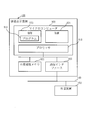
- FIG. 2 is a system configuration diagram of the information display device 100 according to the first embodiment.
- 2 is an example illustrating a hardware configuration of the information display device 100 according to Embodiment 1.
- 5 is a flowchart illustrating an operation procedure of the information display device 100 according to the first embodiment.
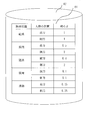
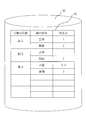
- 5 is an example showing correction data 64 of display data in the first embodiment.
- 5 is an example showing an irradiation state of display information 75 on a road surface in the first embodiment.
- 5 is an example showing a method of irradiating display information 75 to a road surface in the first embodiment.
- 6 is an example showing a method for changing a lighting area of display information 75 on a road surface in the first embodiment.
- 5 is an example showing a method of irradiating display information 75 to a road surface in the first embodiment.
- 5 is an example showing a method of irradiating display information 75 to a road surface in the first embodiment.
- 5 is an example showing a method of irradiating display information 75 to a road surface in the first embodiment.
- 7 is an example showing a method for changing the hue of display information 75 on a road surface according to the first embodiment.
- 10 is a system configuration diagram of an information display device 100 according to Embodiment 2.
- FIG. 15 is an example showing correction data 64 of display data in the second embodiment.
- FIG. *** Configuration description *** FIG. 1 is a configuration diagram of the information display device 100 according to the first embodiment.
- the information display device 100 acquires vehicle information 15 indicating the state of the vehicle from an in-vehicle device such as the vehicle operation control unit 110, the surrounding environment detection unit 120, or the indoor information display unit 130 via the in-vehicle network 140.
- the information display device 100 is a device that determines the state of the vehicle from the vehicle information 15 and outputs the display information 75 to a display surface outside the vehicle based on the display data 55 corresponding to the determined state of the vehicle.
- the vehicle driving control unit 110 is a processing unit that controls driving of the vehicle, such as engine control, brake control, and steering control.
- the surrounding environment detection unit 120 includes a front camera, a rear camera, a LIDAR (Light Detection and Ranging, a Laser Imaging and a Detection and a Ranging), a sonar, a V2X (Vehicle-to-Vehicle, Vehicle-in-the-vehicle, Vehicle-in-the-vehicle illumination device) , A rain sensor, a locator, and the like to acquire information on the surrounding environment of the vehicle.
- LIDAR Light Detection and Ranging, a Laser Imaging and a Detection and a Ranging
- V2X Vehicle-to-Vehicle, Vehicle-in-the-vehicle, Vehicle-in-the-vehicle illumination device
- a rain sensor a locator, and the like to acquire information on the surrounding environment of the vehicle.
- the indoor information display unit 130 is a processing unit that presents information to passengers such as drivers in the room, such as a car navigation device.
- the vehicle information acquisition unit 10 includes an interface device for the in-vehicle network 140 such as a CAN (Controller Area Network) or Ethernet (registered trademark).
- the vehicle information acquisition unit 10 performs a process of acquiring vehicle information 15 indicating the state of the vehicle from the in-vehicle device via the in-vehicle network 140.
- vehicle information 15 for example, operation information of a blinker, an accelerator, a brake, a shift lever, and the like, vehicle state information such as a vehicle speed and a steering wheel drive angle, obstacle information and a pedestrian information detected by a vehicle front camera, and the like are obtained by a locator.
- the vehicle state determination unit 20 determines the state of the vehicle from the vehicle information 15 acquired by the vehicle information acquisition unit 10 and outputs state information 25.
- the state information 25 includes, for example, information indicating the behavior of the vehicle such as backward or forward movement, vehicle state information such as the speed of the vehicle, or obstacle information such as the position of an object around the vehicle.
- the backward movement of the vehicle can be determined from the operation information of the shift lever notified by the vehicle information 15 and the speed of the vehicle.
- the display data acquisition unit 50 includes a display data storage unit 51 and a display data selection unit 52.
- the display data obtaining unit 50 obtains display data 55 for displaying information indicating the state of the vehicle determined by the vehicle state determining unit 20, and outputs the display data 55.
- the display data 55 is data for forming the display information 75, and has the following data. 1. Lighting area shape data, 2. Moving direction data of the lighting area, 3. Lighting time and lighting time data, 4. Lighting area brightness data, 5. Hue data of the lighting area, 6. Sound data or voice data, 7. Other attribute data.
- the display data storage unit 51 stores display data 55 for displaying information presented outside the vehicle for each state of the vehicle.
- the display data 55 stored in the display data storage unit 51 is, for example, animation display data including information to be presented outside the vehicle.
- the display data selection unit 52 performs a process of selecting display data 55 corresponding to the state of the vehicle determined by the vehicle state determination unit 20 from a plurality of display data stored in the display data storage unit 51. .
- the environmental state detection unit 30 is a processing unit that detects an environmental state outside the vehicle.
- the environment state detection unit 30 determines the state of the projection surface on which the display data 55 is projected and the weather state when the display data 55 is projected, and outputs the result as environment information 35.
- the state of the projection surface refers to an uneven state of the road surface, a presence or absence of a puddle, or a road surface state such as dry, wet, submerged, snow-covered, and frozen.
- the weather condition is information relating to the weather such as rain, snow and fog, and information indicating the weather condition such as rainfall and fog density.
- the process of determining the road surface unevenness state, the presence / absence state of the puddle, and the road surface state from the camera information is a known technique, and thus the description thereof is omitted.
- road surface conditions such as dryness and wetness can be obtained from road traffic information, and can also be obtained by a road surface sensor using near infrared rays or the like.
- the person detection unit 40 detects the person 500 around the vehicle and outputs it as the person detection information 45.
- the person 500 is, for example, a pedestrian, a cyclist or an occupant of a car.
- the person detection unit 40 detects the position and orientation of the face of the person or the position and orientation of the face of the occupant of the bicycle or car from the video information of the camera.
- the position of the face can be generally represented by three-dimensional coordinates using a geographic coordinate system.
- the position of the face means a relative position to the display position of the display information 75.
- the positional relationship refers to a relative positional relationship between the position of the person 500 and the display position of the display information 75.
- forward refers to a case where the person 500 is located farther from the vehicle than the display position of the display information 75 in the projection direction indicated by the arrow.
- Lateral refers to a case where the person 500 is beside the projection direction and is on the side of the display position of the display information 75.
- Behind means that the person 500 is at a position closer to the vehicle than the display position of the display information 75 in the projection direction.
- the position of the face of the person 500 is also simply referred to as the position of the person 500.
- the direction of the face can be generally represented by an orientation using north, south, east and west.
- the direction of the face refers to the direction of the face with respect to the display position of the display information 75.
- front means a case where the display information 75 is viewed from the front.
- side surface refers to a case where the display information 75 is obliquely viewed from the side.
- the rear surface refers to a case in which the display information 75 faces backward.
- the face direction is the front.
- the direction of the face of the person 500 is also simply referred to as the direction of the person 500.
- the process of detecting the person 500 from the camera information and the process of detecting the position and orientation of the face of the person are well-known technologies, and thus description thereof will be omitted.
- the determining unit 69 determines the projection mode of the light for displaying the display data based on the visibility of the display information 75.
- the determination unit 69 includes a display data correction unit 60 that outputs corrected data obtained by correcting the display data.
- the corrected data is an example of information indicating a light projection mode. Creating the corrected data by correcting the display data is an example of determining the light projection mode.
- the display data correction unit 60 will be described as a specific example of the determination unit 69.
- the operation of the determination unit 69 described below can be regarded as the operation of the display data correction unit 60, and the operation of the display data correction unit 60 can be regarded as the operation of the determination unit 69.
- the display data correction unit 60 includes a visibility determination unit 61, a correction data storage unit 62, and a correction processing unit 63.
- the display data correction unit 60 determines the visibility of the display information 75 based on the display data 55 at the position of the person 500 around the vehicle, and performs a process of determining an irradiation method suitable for visually recognizing the display information 75.
- the display data correction unit 60 corrects the display data 55 and outputs corrected data 65.
- the display information 75 refers to a display pattern projected on the projection surface 600 based on the display data 55.
- the display information 75 mainly includes a figure and may include a symbol, a character, a sound, and a voice.
- the visibility determining unit 61 estimates the light distribution of the display information 75 output from the information display unit 70 in the current environmental state based on the road surface state and the weather state obtained by the environmental state detecting unit 30.
- the light distribution refers to the output directions of the light emitted from the vehicle and the light reflected from the road surface, and the light intensity in each direction.
- the visibility judging unit 61 recognizes the display information 75 based on the light distribution information of the display information 75 and the position and orientation of the face of the person 500 who visually recognizes the display information 75 obtained by the person detecting unit 40. The visibility of the display information 75 viewed from the position of the nearby person 500 is determined.
- the visibility refers to the degree of collapse or dazzling of the figure of the display information 75 when viewed from the position of the person 500.
- the visibility determining unit 61 determines a display position and an angle at which the display information 75 is irradiated based on the visibility determination result. Based on the determined display position and angle of the display information 75, the positional relationship between the person 500 who visually recognizes the display information 75 and the display information 75 is obtained.
- the correction data storage unit 62 stores correction data 64 for correcting the display data 55 in accordance with the environmental state and the position of the person 500.
- the correction data 64 stored in the correction data storage unit 62 visually recognizes, for example, road surface conditions such as dryness, wetness, and freezing, and display information 75 viewed from the position of the display information 75 such as front, side, and rear. This is data relating to light intensity according to the position of the person 500.
- the correction processing unit 63 displays the road surface condition, the weather condition, the positional relationship between the person 500 and the display information 75, and the correction data 64 stored in the correction data storage unit 62.
- the luminance or hue at the time of irradiating the information 75 is determined. Further, the horizontal direction angle and the vertical direction angle are obtained as the irradiation direction of the display information 75 from the display position and the angle of the display information 75 obtained by the visibility determining section 61.
- the information display unit 70 displays display information on the projection surface based on the light projection mode determined by the determination unit 69. Specifically, the information display unit 70 irradiates the display information 75 on the road surface or another projection surface 600 based on the corrected data 65. The information display unit 70 performs a process of displaying information to the outside of the vehicle according to the corrected data 65 output from the display data correction unit 60.
- the light irradiation unit 71 of the information display unit 70 irradiates, for example, laser light or LED (Light Emitting Diode) light to the projection surface 600 outside the vehicle according to the corrected data 65 output from the display data correction unit 60. Thus, information indicating the state of the vehicle is displayed on the projection surface 600.
- the light projection surface 600 a road surface around the vehicle, a wall surface around the vehicle, a surface of a building around the vehicle, a surface of an installation around the vehicle, a body of the vehicle, a window of the vehicle, and the like are considered. Is included in the projection surface outside the vehicle.
- FIG. 2 is an example showing a hardware configuration of the information display device 100 according to the first embodiment.
- the information display device 100 includes, as main components, a microcomputer 900 including a ROM 920, a RAM 921, and a processor 910, a nonvolatile memory 922, and a communication unit that is a communication interface 923 with a vehicle-mounted device.
- the communication interface 923 communicates with an external device 150 such as an in-vehicle device via the in-vehicle network 140.
- the vehicle information acquisition unit 10, the vehicle state determination unit 20, the display data acquisition unit 50, the display data correction unit 60, the environment state detection unit 30, the person detection unit 40, and the information display unit 70 are all implemented by one device.
- a configuration that realizes this, or a configuration that realizes only the information display unit 70 by another device may be used. That is, the combination of the processing units is arbitrary. In the case of realizing with a plurality of devices, data is mutually exchanged by a communication interface provided in each device.
- the processor 910 is a device that executes the program 930.
- the processor 910 is an IC (Integrated Circuit) that performs arithmetic processing.
- a specific example of the processor 910 is a CPU (Central Processing Unit), a DSP (Digital Signal Processor), or a GPU (Graphics Processing Unit).
- the RAM 921 is a storage device that temporarily stores data.
- a specific example of the RAM 921 is an SRAM (Static Random Access Memory) or a DRAM (Dynamic Random Access Memory).
- the ROM 920 is a storage device that stores data permanently.
- the ROM 920 stores a program 930.
- the nonvolatile memory 922 is a storage device that stores data.
- a specific example of the nonvolatile memory 922 is an HDD.
- the nonvolatile memory 922 may be a portable storage medium such as a memory card, a NAND flash, a flexible disk, an optical disk, and a compact disk.
- the communication interface 923 includes a receiving unit that receives data and a transmitting unit that transmits data.
- the communication interface 923 includes, for example, a communication chip or a NIC (Network Interface Card).
- the program 930 implements the functions of the vehicle information acquisition unit 10, the vehicle state determination unit 20, the display data acquisition unit 50, the display data correction unit 60, the environment state detection unit 30, the person detection unit 40, and the information display unit 70.
- This is an information display program.
- the information display program is read into the processor 910 from the ROM 920 and executed by the processor 910.
- the ROM 920 stores not only an information display program but also an OS (Operating System).
- the processor 910 executes the information display program while executing the OS.
- the information display program and the OS may be stored in the nonvolatile memory 922.
- the information display program and the OS stored in the nonvolatile memory 922 are loaded into the RAM 921 and executed by the processor 910. Note that part or all of the information display program may be incorporated in the OS.
- the information display device 100 may include a plurality of processors instead of the processor 910.
- the plurality of processors share execution of the information display program.
- Each processor is a device that executes an information display program, similarly to the processor 910.
- Data, information, signal values, and variable values used, processed, or output by the information display program are stored in the RAM 921, the nonvolatile memory 922, or a register or a cache memory in the processor 910.
- the “parts” of the vehicle information acquisition unit 10, the vehicle state determination unit 20, the display data acquisition unit 50, the display data correction unit 60, the environmental state detection unit 30, the person detection unit 40, and the information display unit 70 are referred to as “parts”. It may be read as “processing”, “procedure” or “step”.
- the “processing” of each processing of the vehicle information acquisition unit 10, the vehicle state determination unit 20, the display data acquisition unit 50, the display data correction unit 60, the environment state detection unit 30, the person detection unit 40, and the information display unit 70 "May be read as” program, "" program product, "or” computer-readable storage medium recording the program.
- the information display program causes a computer to execute each process, each procedure, or each process in which the “unit” of each unit is replaced with “process”, “procedure”, or “process”.
- the information display method is a method performed by the information display device 100 executing an information display program.
- the information display program may be provided by being stored in a computer-readable recording medium. Further, the information display program may be provided as a program product.
- the information display device 100 may be a circuit such as a logic IC (Integrated Circuit), a GA (Gate Array), an ASIC (Application Specific Integrated Circuit), or an FPGA (Field-Programmable Array).
- a logic IC Integrated Circuit
- GA Gate Array
- ASIC Application Specific Integrated Circuit
- FPGA Field-Programmable Array
- processing circuitry The general concept of a processor, a memory, a combination of a processor and a memory, and a processing circuit is referred to as “processing circuitry”. That is, the processor, the memory, the combination of the processor and the memory, and the processing circuit are each a specific example of “processing circuitry”.
- FIG. 3 is a flowchart showing an information display method which is a processing procedure of information display device 100 according to the first embodiment of the present invention.
- the information display device 100 executes the following flow.
- Step 1 Vehicle information acquisition step by vehicle information acquisition unit 10>
- the vehicle information acquisition unit 10 acquires vehicle information 15 indicating the state of the vehicle from the in-vehicle device via the in-vehicle network 140, and outputs the vehicle information 15 to the vehicle state determination unit 20.
- Step 2 Vehicle state determination step by vehicle state determination unit 20>
- the vehicle state determination unit 20 receives the vehicle information 15 from the vehicle information acquisition unit 10, determines the state of the vehicle from the vehicle information 15, and outputs state information 25.
- the state information 25 includes, for example, information indicating the behavior of the vehicle such as backward or forward movement, vehicle state information such as the speed of the vehicle, and obstacle information around the vehicle. For example, when the vehicle starts to retreat, it can be determined from the operation information of the shift lever notified by the vehicle information 15.
- Step 3 Display data acquisition step by display data acquisition unit 50>
- the display data selection unit 52 of the display data acquisition unit 50 converts the display data 55 corresponding to the vehicle state determined by the vehicle state determination unit 20 from the plurality of display data stored in the display data storage unit 51. select.
- the data stored in the display data storage unit 51 is information to be presented to the outside of the vehicle for each state of the vehicle, and is animation display data 55 including information to be presented to the outside of the vehicle.
- the animation data is data of a graphic such as an arrow or a moving image pattern in which the traveling direction of the vehicle is transmitted.
- the display data selection unit 52 selects, as the display data 55, an arrow graphic displayed behind the vehicle. If the vehicle state determined by the vehicle state determination unit 20 is retreating and a pedestrian is detected as an obstacle around the vehicle, the display data selection unit 52 displays a red color indicating that the movement of the vehicle is more transmitted. The display data 55 or the display data 55 including the blinking pattern is selected. The display data acquisition unit 50 outputs the display data 55 selected by the display data selection unit 52.
- Step 4 Detection Step by Environmental Condition Detection Unit 30 and Person Detection Unit 40> From the vehicle information 15 acquired by the vehicle information acquisition unit 10, the environmental state detection unit 30 determines the state of the projection surface that projects the display information 75 or the weather state when the display information 75 is projected, as the environment state outside the vehicle. The determination is made and the environmental state is output as environmental information 35.
- the environmental state detection unit 30 detects the state of the road surface, the presence or absence of a puddle, from the image information of the vehicle front camera or the vehicle rear camera in the vehicle information 15 acquired by the vehicle information acquisition unit 10 as the state of the projection surface. Further, road surface conditions such as dry, wet, submerged, snow-covered, and frozen are determined. The environmental condition detection unit 30 determines whether the vehicle information 15 as the weather condition from the vehicle information 15 acquired by the vehicle information acquisition unit 10 based on the rainfall information acquired by the rain sensor or the weather information around the vehicle acquired by the car navigation device. Information on the weather, such as rain, snow, and fog, and the degree of weather, such as rainfall and fog density, are detected.
- the person detection unit 40 detects a person 500 around the vehicle from the image information of the vehicle front camera or the vehicle rear camera in the vehicle information 15 acquired by the vehicle information acquisition unit 10, and outputs the person 500 as the person detection information 45. .
- the person detection unit 40 detects the position and orientation of the face of a pedestrian, a cyclist, or a vehicle occupant from the video information of the camera.
- Step 5 Determination Step by Display Data Correction Unit 60>
- the visibility determination unit 61 of the display data correction unit 60 determines the light distribution of the display information 75 output from the information display unit 70 in the current irradiation state based on the road surface state and the weather state obtained by the environmental state detection unit 30. Is estimated.
- the visibility determination unit 61 converts the display information 75 based on the light distribution information of the display information 75 and the position and orientation of the face of the person 500 who visually recognizes the display information 75 obtained by the person detection unit 40.
- the visibility of the display information 75 viewed from the position of the person 500 around the vehicle to be visually recognized is determined.
- the visibility determining unit 61 determines a position and an angle at which the display information 75 is irradiated based on the visibility determination result.
- the visibility determining unit 61 obtains the positional relationship between the person 500 who visually recognizes the display information 75 and the display information 75 based on the determined display position and angle of the display information 75.
- the correction processing unit 63 of the display data correction unit 60 corrects the road surface state obtained by the visibility determination unit 61, the weather state, the positional relationship between the person 500 and the display information 75, and the correction stored in the correction data storage unit 62. Based on the data 64, the luminance or hue at the time of irradiating the display information 75 is determined. Further, the correction processing unit 63 obtains the horizontal direction angle and the vertical direction angle as the irradiation direction of the display information 75 from the display position and the angle of the display information 75 obtained by the visibility determining unit 61.
- FIG. 4 shows a specific example of the correction data 64 when the face direction is the front.
- the correction data storage unit 62 also stores the correction data when the face direction is the side surface and the rear surface.
- the road surface state and the position of the person are combined, and the brightness of the light when the display information 75 is output is stored for each combination.
- the correction processing unit 63 performs correction to double the brightness. A specific example regarding the processing of the display data correction unit 60 will be described later.
- Step 7 Information Display Step by Information Display Unit 70>
- the information display unit 70 irradiates the display information 75 on the road surface based on the corrected data 65.
- the light irradiating section 71 of the information display section 70 irradiates laser light or LED light to the projection surface 600 outside the vehicle toward the outside of the vehicle according to the corrected data 65 output from the display data correcting section 60.
- the irradiation angle of the light irradiation unit 71 is adjusted based on the horizontal direction angle and the vertical direction angle obtained by the display data correction unit 60.
- the adjustment of the irradiation angle of the light irradiation unit 71 may be a mechanism for controlling the position of the light irradiation unit 71 using a motor, or a mechanism for controlling the position where light is irradiated by mounting a shade and changing the position of the shade. May be.
- a plurality of light sources may be prepared in the light irradiation unit 71, and only the light source corresponding to the irradiation position may be turned on. A specific example regarding the display processing of the information display unit 70 will be described later.
- Display Data Correction Process of Display Data Correction Unit 60 and Display Process of Information Display Unit 70 >> Hereinafter, specific examples of the display data correction process of the display data correction unit 60 and the display process of the information display unit 70 will be described.
- the visibility determination unit 61 of the display data correction unit 60 determines the unevenness of the road surface serving as the projection surface 600 of the display information 75 based on the road surface condition obtained by the environmental condition detection unit 30.
- a display data when a figure having both a lighting area and a light-off area is displayed, on a road with severe road surface unevenness or a snowy road, light is irregularly reflected on the road surface, and when the display information 75 is viewed from the front, the display information is displayed. 75 figures collapse and look. On the other hand, when the figure is viewed from behind, the way the figure collapses is small, and the figure of the display information 75 can be visually recognized in the plan.
- FIG. 5 (a) shows how the normal road surface display information 75 looks.
- FIG. 5B shows how the display information 75 on a road surface with severe unevenness is seen.
- the visibility determination unit 61 determines the visibility of the display information 75 viewed from the position of the person 500 around the vehicle that views the display information 75 from the position and orientation of the person 500 who views the display information 75 obtained by the person detection unit 40. Is determined. In other words, the degree of collapse of the figure is large from the person 500 located in front of the display information 75, and the degree of collapse is small for the person 500 located behind the display information 75, depending on the position of the person 500. judge.
- the correction processing unit 63 does not correct the display data 55, and the display data acquired by the display data acquisition unit 50 is not corrected. 55 is output as corrected data 65.
- the correction processing unit 63 detects a place on the road surface to which the display information 75 is irradiated with a small amount of unevenness on the road surface and irradiates the place with a small amount of unevenness on the road surface. In order to make it possible to generate the corrected data 65, the irradiation angle at which the display information 75 is irradiated is changed in the horizontal direction.
- the correction processing unit 63 detects a place where the road surface has less unevenness
- the road surface is irradiated with lattice-like light
- the irradiated lattice-like light is photographed by a camera
- the image is taken from an image photographed by the camera.
- a known method of estimating a road surface state from an image captured by a camera may be used.
- the information display unit 70 outputs the display information 75 to the projection plane 600 according to the corrected data 65 corrected by the display data correction unit 60.
- the method of changing the light irradiation angle can be realized by attaching a motor to the light irradiation unit 71 and changing the angle of the light irradiation unit 71 by controlling the motor. Further, it can be realized by selecting a light source to be turned on as the light irradiating unit 71 composed of a plurality of light sources, or by changing the position to irradiate light by providing a shade in the light irradiating unit 71 and controlling the shade.
- ⁇ Switching display position switching display position by selecting light irradiation unit 71> A case where the road information is uneven and the display information 75 is difficult to see will be described.
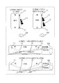
- a plurality of light irradiation units 71 are physically attached before and after in the traveling direction of the vehicle, and based on the state of the road surface whether the road surface is uneven or not, The case where one of the light irradiation units 71 is selected to project the display data will be described. As shown in FIG.
- the plurality of light irradiation units 71 display the same display information at the same position in the front-rear direction of the vehicle (the center position in the front-rear direction of the vehicle). Can do it.
- FIG. 8B when the road surface is uneven between the front end and the rear end of the vehicle, the display positions of the plurality of light irradiation units 71 change.
- FIG. 8C when the road information between the front end and the rear end of the vehicle has a mountain-like undulation, it is difficult to visually recognize the display information 75 when the display information 75 is projected on a slope far from the person 500. If 75 is projected on a slope close to the person 500, it becomes easier to see. As shown in FIG.
- the visibility determination unit 61 of the determination unit 69 determines the undulation state of the road surface serving as the projection surface 600 of the display information 75 from the road surface state obtained by the environment state detection unit 30 and determines whether the display information 75 is difficult to see. judge.
- the visibility determining unit 61 determines whether or not the display information 75 is difficult to see, the road surface has undulations, and the light irradiating unit 71 irradiates light in a direction approaching the person 500. It is determined that it is difficult to see in that case. As shown in (c) and (d) of FIG. 8, when the position of the person is on the front side of the vehicle, it is difficult to see if the light irradiation direction is from back to front. As described above, the determining unit 69 determines the visibility of the display information based on the environmental state of the undulation of the road surface and the positional relationship between the light projection direction and the position of the person.
- the light projection direction includes a projection direction approaching the person 500 and a projection direction moving away from the person 500.
- the projection direction approaching the person 500 refers to a case where display information is displayed between the light irradiation unit 71 and the person 500.
- the projection direction moving away from the person 500 refers to a case where display information is displayed other than between the light irradiation unit 71 and the person 500.
- the visibility determination unit 61 determines the inclination angle of the road surface on which the display information 75 is displayed based on the road surface state obtained by the environmental state detection unit 30.
- the inclination angle of the line of sight of the person 500 is determined from the position of the person 500 and the position where the display information 75 is displayed, and the intersection angle ⁇ formed by the inclination angle of the road surface and the inclination angle of the line of sight of the person 500 is a predetermined threshold value. If it is below, it may be determined that it is difficult to see.
- the determination unit 69 determines whether to switch the light irradiation unit 71 or not.
- the determination unit 69 determines the inclination angle of the road surface from the road surface state obtained by the environmental state detection unit 30, and the position of the person 500 and the display information 75 are displayed.
- the inclination angle of the line of sight of the person 500 is determined based on the position of the person 500, and the magnitude of the intersection angle ⁇ formed by the inclination angle of the road surface and the inclination angle of the line of sight of the person 500 is determined.
- the determination unit 69 selects the front light irradiation unit 71 having the large intersection angle ⁇ . In FIG.
- the determination unit 69 selects the front light irradiation unit 71 having the large intersection angle ⁇ .
- the determination unit 69 selects the rear light irradiation unit 71 having a large intersection angle ⁇ .
- the determination unit 69 selects the rear light irradiation unit 71 having a large intersection angle ⁇ .
- the relationship among the undulating state of the road surface, the position of the person, and the light irradiation direction is as follows.
- the deciding unit 69 may select the light irradiating unit 71 that irradiates light in an irradiation direction away from the person 500.
- the determination unit 69 selects the light irradiation unit 71 in consideration of the following two points.
- the correction processing unit 63 of the determination unit 69 creates data for switching the light irradiation unit 71.
- the information display unit 70 switches the light irradiation unit 71 based on the data for switching the light irradiation unit 71, and outputs display information 75 to the projection plane 600.
- the determination unit 69 determines the visibility of the display information to be projected based on the environmental state, the position of the person, and the projection direction of the light, and determines the visibility of the light for displaying the display information based on the visibility. Determine the projection mode.
- the determination unit 69 determines the light projection direction, and includes data instructing switching of the light irradiation unit 71 in the information indicating the light projection mode.
- the number of the light irradiation units 71 may be three or more.
- the case where the road surface has undulations is not limited to a mountain-like or valley-like shape, and may be a road surface having unevenness due to snow, a road surface having severe unevenness, or a sloped road surface such as a slope.
- the specifications of the display data 55 are changed.
- a method of changing the specifications of the display data 55 there are a method of increasing the spatial contrast and a method of increasing the temporal contrast.
- the correction processing unit 63 enhances the spatial contrast by correcting the display data 55 so as to increase the interval between the light-on region and the light-off region of the display data 55.
- FIG. 6B shows display information 75 based on corrected data corrected so that the interval between the light-on area and the light-off area of the display information 75 is widened on a road surface with severe unevenness.
- the correction processing unit 63 corrects the display data 55 so as to increase the lighting time, thereby increasing the temporal contrast.
- the information display unit 70 outputs the display information 75 to the projection plane 600 according to the corrected data 65 corrected by the display data correction unit 60.
- the display data 55 can be changed by providing a shade in the light irradiation unit 71 and controlling the shade.
- As a shade control method two shades are prepared, and the gap between the light-on area and the light-off area can be changed at a desired interval by shifting the overlapping position of the shades.
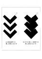
- FIG. 7A shows a front shade 201 having a V-shaped light transmitting portion 211.
- FIG. 7B shows the rear shade 202 having the V-shaped light shielding portion 212.
- FIG. 7C shows a normal display method in which the rear shade 202 is not overlapped with the front shade 201. In the case of FIG. 7C, light is emitted from the V-shaped light transmitting portion 211 of the front shade 201. In the case of FIG. 7C, the lighting region 230 is formed by the entire V-shaped light transmitting portion 211 of the front shade 201.
- FIG. 7D shows a display method in which the rear shade 202 is slid in the direction of the arrow with respect to the front shade 201 to reduce the lighting area of the front shade 201.
- the V-shaped light-transmitting portion 211 of the front shade 201 is covered about half by the V-shaped light-shielding portion 212 of the rear shade 202.
- a lighting area 240 that is half of the V-shaped light transmitting portion 211 of the front shade 201 is formed.
- the light reflected by the road surface condition is diffused on the road surface if it is in a dry state, so that it can be seen at the same brightness even when viewed from any position around the display pattern.
- the road surface is covered with a water film, as in a submerged state, the light reflected from the road is strongly reflected and the diffused light is weak.
- the display pattern is viewed from the front and front, the brightness appears to increase, and when the display pattern is viewed from the side or the back, the display pattern looks dark.
- the road surface condition is dry, the light distribution of the display information 75 is approximately equal in light intensity at any angle around the display pattern, and when the road condition is submerged, the light distribution of the display information 75 is displayed.
- the light intensity is high in the front and front directions around the pattern, and weak in the side and rear directions.
- the road surface state is a snow-covered state, light is diffused on the road surface, but since the reflectance of snow is high, the brightness appears to increase even from any position around the display pattern.
- the visibility determining unit 61 determines the position of the person 500 around the vehicle that visually recognizes the display information 75 from the light distribution distribution information of the display information 75 and the position and orientation of the person 500 who visually recognizes the display information 75 obtained by the person detection unit 40.
- the visibility of the display information 75 as viewed from is determined. That is, for example, if the road surface state is a submerged state, the person 500 located in front of the display information 75 feels dazzling the display information 75, and the person 500 located on the side or behind the display information 75 has display information. A difference in visibility depending on the position of the person 500, such as 75 being dark, is determined.
- the correction processing unit 63 sets the visibility of the display information 75 such that the brightness of the emitted light is reduced when the display information 75 is dazzling, and the brightness of the emitted light is increased when the display information 75 is dark. Then, the display data 55 is corrected.
- FIG. 9 illustrates a specific example in which the visibility of the display information is determined based on the position of the person and the environmental state, the light projection mode is determined based on the visibility, and information on the determined projection mode is output.
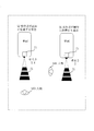
- FIG. 9A shows an example in which the brightness is set to 0.4 since the pedestrian is located ahead.
- FIG. 9B shows an example in which the brightness is set to 2 because the pedestrian is located on the side.
- FIG. 9 shows a case where the road surface state is a flooded state. As shown in FIG. 4, when the road surface state is a flooded state and the position of the person is ahead, the correction processing unit 63 sets the brightness to 0. .4 times correction.
- the correction processing unit 63 performs correction to double the brightness.
- the reflected light from the road surface becomes strong, so that the brightness is reduced regardless of the position of the person.
- the brightness is set to 0.5 at normal time (when the road surface condition is dry)
- the diffused light is weakened, and the visibility is reduced.
- the display information is displayed as "2 times,” the visibility of the display pattern viewed from the person can be increased even when the road surface state is flooded and the person is on the side.
- the correction processing unit 63 performs the visibility determination for all the persons 500, and corrects them so that the visibility of all the persons 500 becomes equal.
- the correction processing unit 63 performs correction so that the visibility of the person 500 who needs to communicate the state of the vehicle is high.
- the person 500 with a high need to convey the state of the vehicle may be the person 500 closest to the vehicle, or may be an attribute of the target person 500, such as the age of the person 500. Good.
- the information display unit 70 outputs the display information 75 to the projection plane 600 according to the corrected data 65 corrected by the display data correction unit 60.
- the reflected light from the road surface has a strong regular reflection light and a weak diffused light, as described above.
- the brightness increases, and when viewed from the side or rear, the display pattern appears dark.
- the intensity of the reflected light from the road surface varies depending on the angle at which the reflected light from the road surface is output. For this reason, the appearance of light differs depending on the height of the person 500 who is to view the display pattern. In particular, the larger the angle at which the light enters the road surface and the angle at which the reflected light from the road surface is output, the larger the value.
- the visibility determination unit 61 determines the person 500 around the vehicle that visually recognizes the display information 75 from the light distribution distribution information of the display information 75 and the position and orientation of the face of the person 500 who visually recognizes the display information 75 obtained by the person detection unit 40. The visibility of the display information 75 viewed from the position is determined.
- the correction processing unit 63 sets the angle between the angle at which light enters the road surface and the position of the face of the person 500 to be large.
- the irradiation angle for irradiating light is changed in the vertical direction.
- FIG. 10 shows an example in which the incident angle is set to a normal incident angle in a dry state.
- FIG. 10B shows an example in which the angle of incidence is small so that the reflected light does not hit the position of the face of the person 500 in the wet state.
- the information display unit 70 outputs the display information 75 to the projection plane 600 according to the corrected data 65 corrected by the display data correction unit 60.
- the method of changing the light irradiation angle can be realized by attaching a motor to the light irradiation unit 71 and changing the angle of the light irradiation unit 71 by controlling the motor. Alternatively, it can also be realized by selecting the light source to be turned on as the light irradiation unit 71 including a plurality of light sources. Further, it can also be realized by providing a shade in the light irradiation unit 71 and changing the angle by controlling the shade.
- a color having a high color temperature that is, white light
- the color temperature is low, that is, an illumination color (yellow).
- an illumination color yellow
- a color having a low color temperature that is, an illumination color (yellow) is preferred even when the weather condition is fog.
- the correction processing unit 63 of the display data correction unit 60 changes the hue of the display information 75 based on the weather condition obtained by the environmental condition detection unit 30.
- the correction processing unit 63 changes the color temperature to a higher color when the road surface state is dry, and changes the hue of the display information 75 to a lower color temperature when the road surface state is wet or submerged. to correct.
- the information display unit 70 outputs the display information 75 to the projection plane 600 according to the display data corrected by the display data correction unit 60.
- the method of changing the hue of light can be realized by configuring the light irradiation unit 71 with white and yellow LEDs and blinking the white and yellow LEDs at high speed. When outputting in a color close to white, both LEDs are blinked so that the lighting time of the white LED is long and the lighting time of the yellow LED is short.
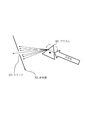
- the light irradiation unit 71 may be provided with a prism 301 and a light shielding plate 303 having a slit 302 at the tip of the prism 301. It is known that when white light passes through the prism 301, the direction of the light exiting the prism 301 changes depending on the wavelength (dispersion).
- the prism 301 is irradiated with light, and only a part of the light split by the prism 301 passes through the slit 302. By rotating the prism 301, only light of a desired color can be output.
- FIG. 11 shows an example in which the prism 301 is rotated behind the light shielding plate 303, and only a part of the light split by the prism 301 passes through the slit 302.
- a structure using a diffraction grating or the like instead of the prism 301 may be used as a dispersion element for dispersing light.
- the light irradiating unit 71 of the information display unit 70 uses laser light, there is a risk of harm to the person 500 around the vehicle. For this reason, when the road surface state detected by the environmental state detection unit 30 is a road surface state such as a severe road surface state, a flooded state, or a frozen state, LED light is used without using laser light. When there are a plurality of persons 500 detected by the person detection unit 40 and the display information 75 cannot be output in a direction in which the persons 500 do not exist, LED light is used without using laser light.
- the display data correction unit 60 detects a road surface state such as a severely uneven road surface state, a flooded state, or a frozen state as the road surface state detected by the environmental state detection unit 30, a display output to the information display unit 70.
- the data is corrected from laser light to LED light.
- the display data correction unit 60 when there are a plurality of persons 500 detected by the person detection unit 40 and the display information 75 cannot be output in a direction in which no person 500 exists, the display data correction unit 60 outputs the display information 75 to the information display unit 70.
- the display data is corrected from laser light to LED light.
- the information display unit 70 outputs the display information 75 to the projection plane 600 according to the corrected data 65 corrected by the display data correction unit 60.
- the corrected data 65 indicates that the display information 75 is output using laser light
- the information display unit 70 projects the display information 75 on the projection surface 600 using laser light.
- the corrected data 65 indicates that the display information 75 is output using LED light
- the information display unit 70 projects the display information 75 on the projection surface 600 using the LED light.
- the information display device 100 includes: A person detection unit 40 that detects a position of a person, An environmental state detection unit 30 that detects an external environmental state of the vehicle; Based on the position of the person detected by the person detection unit 40 and the environment state detected by the environment state detection unit 30, the visibility of the display information projected on the projection surface 600 is determined, and the display information is determined based on the visibility.
- the information display device 100 includes a vehicle information acquisition unit 10 that acquires the vehicle information 15 from the in-vehicle network 140 and a vehicle state that determines the state of the vehicle based on the vehicle information 15 acquired by the vehicle information acquisition unit 10. It includes a determination unit 20 and an environment state detection unit 30 that detects a state of a projection surface outside the vehicle and a weather state outside the vehicle as an environment state. In addition, the information display device 100 includes a person detection unit 40 that detects the position and the direction of the person 500. Further, the information display device 100 includes a display data acquisition unit 50 that acquires display data 55 for displaying information based on the vehicle state determined by the vehicle state determination unit 20.
- the information display device 100 determines the visibility of the display information 75 displayed by the display data 55 acquired by the display data acquisition unit 50 based on the position and orientation of the person 500 detected by the person detection unit 40.
- a display data correction unit 60 that corrects the display data 55 based on visibility and outputs corrected data 65 is provided.
- the information display device 100 includes an information display unit 70 that displays information based on the corrected data 65 output by the display data correction unit 60.
- the display data correction unit 60 displays the display data based on the state of the projection surface detected by the environmental condition detection unit 30, the weather condition outside the vehicle, and the position and orientation information of the person 500 detected by the person detection unit 40. Correct 55.
- the information display unit 70 displays the state of the vehicle on the projection surface 600 by irradiating light to the projection surface 600 outside the vehicle based on the corrected data 65.
- the display data correction unit 60 determines the visibility of the display information 75 viewed from the person 500 based on the position of the person 500 and the direction of the face.
- the display data correction unit 60 creates at least one of the following corrected data 65 (light projection mode) according to the visibility of the display information 75.
- Corrected data 65 for switching the display position of the display information 75; 2.
- Corrected data 65 for switching the spatial contrast of the display information 75, 3.
- Corrected data 65 for switching the temporal contrast of the display information 75, 4.
- Corrected data 65 for switching the brightness of the display information 75; 5.
- the display data correction unit 60 irradiates the grid-like light from the information display unit 70 to the projection surface 600, shoots the illuminated grid-like light with a camera, and calculates the degree of collapse of the grid-like light from the image captured by the camera. Detect the unevenness state of the projection surface 600.
- the information display unit 70 includes a plurality of shades, and includes a light irradiation unit 71 that displays display information 75 based on the corrected data 65 by shifting the overlapping position of the plurality of shades.
- the information display unit 70 includes a light irradiation unit 71 having a dispersive element that changes the hue of the display information 75.
- the information display unit 70 has a plurality of types of light sources, and displays the display information 75 by switching the light sources.
- the display data correction unit 60 corrects the display data 55 based on the number of persons or the attributes of the persons.
- person detection unit 40 detects the position and orientation of person 500, and display data selection unit 52 selects display data 55 for displaying information.
- the display data correction unit 60 determines the visibility of the display information 75 displayed by the display data 55 selected by the display data selection unit 52 based on the position and orientation of the person 500 detected by the person detection unit 40.
- the display data 55 is corrected based on the visibility, and the corrected data 65 is output.
- the information display unit 70 displays information on the road surface based on the corrected data 65 output by the display data correction unit 60.
- the position of the person 500 outside the vehicle is detected, and the light projection mode is determined in consideration of the visibility of the person 500 at this position. It is possible to project a light pattern with high visibility (easy transmission of intention) for the person 500. Further, according to the information display apparatus 100 and the information display method of the first embodiment, the light projection mode in consideration of the visibility of the target person in accordance with the combination of the environment such as the weather and the road surface environment and the position of the person 500. Is determined, a light pattern with high visibility suitable for a combination of the environment and the position of the person 500 can be projected.
- the visibility of the light of the target person changes according to the environment and the position of the person, and therefore, by projecting a light pattern corresponding to a combination of these, under a specific environment, The visibility of the light pattern at the position of the person can be improved.
- the information display device 100 and the information display method of the first embodiment by correcting the display data in accordance with the environment or weather, the positional relationship between the display information 75 and the person 500, in various situations. Also, a display that is easy to see for the person 500 can be projected on the road surface.
- the display data correction unit 60 determines the visibility of the display information 75 based on the display data 55 when viewed from the position of the person 500.
- the display mode of the display information 75 By changing the display mode of the display information 75 based on the determination result of the visibility, the display pattern of the display information 75 can be prevented from being broken, and the visibility of the display information 75 viewed from the person 500 can be avoided. Can be increased.
- a graphic such as an arrow is used as a display pattern to be displayed outside the vehicle, light is diffused on a road surface or a snowy surface having severe unevenness, but the information display device 100 according to the first embodiment.
- the information display method it is possible to prevent the shape of the displayed figure from being distorted, and the transmission of information is not reduced.
- reflected light from the road surface increases.
- the information display device 100 and the information display method of the first embodiment when a display pattern is confirmed. There is no dazzling and information transmission does not decrease.
- the reflected light from the road surface becomes stronger, the intensity of light in front increases, the diffused light becomes weaker, and the intensity of light on the side decreases, According to the information display device 100 and the information display method of the first aspect, the visibility of the figure from the side does not decrease, and the transmission of information does not decrease.
- the display data correction unit 60 for correcting display data has been described as a specific example of the determination unit 69.
- the determination unit 69 is not limited to the case where the display data selected by the display data selection unit 52 is corrected. New data that does not exist, new attributes, new shapes, and the like may be added to the display data to determine the light projection mode.
- the determination unit 69 may use only new data, a new attribute, a new shape, and the like as the light projection mode without using the existing display data at all. That is, the projection mode determined by the determination unit 69 may be any projection mode as long as the visibility of the display data is improved according to the position of the person.
- the person detection unit 40 may detect only the position of the face of the person 500 and output the detected position as the person detection information 45. When the person detection unit 40 detects only the position of the person 500, it may be assumed that the face of the person 500 always faces the display information 75 in front.
- the information display device 100 may be mounted on a two-wheeled vehicle, a three-wheeled vehicle, a ship, a walker, and other moving objects, instead of an automobile.
- the person detection unit 40 may perform the following detection. 1. Detection of only the position of the person 500, 2. Motion detection of person 500 (while still, walking, running, piggyback, hug, pet band), 3. State detection of the person 500 (while operating a smartphone, talking on a smartphone, watching on an earphone, wearing sunglasses, wearing goggles, wearing a helmet, pulling a cart, using a cane, using a wheelchair), 4. Attribute detection of person 500 (adult, child, elderly, foreigner, height) The display data correction unit 60 performs correction according to the detection content of the person detection unit 40.
- FIG. 12 is a configuration diagram of the information display device 100 according to the second embodiment.
- FIG. 12 is obtained by removing the vehicle operation control unit 110, the indoor information display unit 130, the vehicle state determination unit 20, and the environment state detection unit 30 from FIG. 1 described in the first embodiment.
- the information display device 100 includes a person detection unit 40 that detects the position and orientation of the person 500, and a display data acquisition unit 50 that acquires display data 55 that displays information.
- the information display device 100 determines the visibility of the display information 75 displayed by the display data 55 acquired by the display data acquisition unit 50 based on the position and orientation of the person 500 detected by the person detection unit 40, and A display data correction unit that corrects the display data based on the characteristics and outputs corrected data.
- the information display device 100 includes an information display unit 70 that displays information based on the corrected data 65 output by the display data correction unit 60.
- the display data correction unit 60 determines the visibility of the display information 75 viewed from the person 500 based on the position of the person 500 and the direction of the face.
- the information display device 100 operates when the person detection unit 40 detects the person 500.
- Step 5 Determination Step by Display Data Correction Unit 60>
- the visibility determining unit 61 looks at the display information 75 obtained from the person detection unit 40 based on only the position and orientation of the face of the person 500 who visually recognizes the display information 75 from the position of the person 500 around the vehicle that visually recognizes the display information 75.
- the visibility of the display information 75 based on the display data 55 is determined.
- the visibility determining unit 61 determines the irradiation position and angle based on the visibility determination result.
- the visibility determining unit 61 obtains a positional relationship between the person 500 who visually recognizes the display information 75 and the display information 75 based on the determined display position and angle of the display information 75.
- the correction processing unit 63 of the display data correction unit 60 calculates the display information based on the positional relationship between the person 500 obtained by the visibility determination unit 61 and the display information 75 and the correction data 64 stored in the correction data storage unit 62. Determine the brightness or hue when illuminating 75. Further, the correction processing unit 63 obtains a horizontal angle and a vertical angle as the irradiation direction of the display data 55 from the display position and the angle of the display data 55 obtained by the visibility determining unit 61.
- the correction data 64 stored in the correction data storage unit 62 is, for example, data relating to the light intensity according to the position of the person 500 who views the display information 75 and the direction of the face.
- FIG. 13 shows a specific example of the correction data 64 stored in the correction data storage unit 62.
- the position of the person and the direction of the face are combined, and the brightness of light when the display information 75 is output for each combination is stored.
- the correction processing unit 63 determines that the pedestrian's face is in front. A correction is made to double the brightness as compared with the state (a state where the display information 75 is viewed straight).
- the information display device 100 can be operated only by the person detection unit 40 detecting the person 500. Therefore, the information display device 100 can be operated even when the vehicle is not operated.
- the information display device 100 may be mounted on a building, a traffic signal, or another installed object instead of a mobile object.
- the person detection unit 40 also detects the moving direction of the person 500, and the display data correction unit 60 considers the position of the person 500, the face direction, and the moving direction. , The display data 55 may be corrected.
- the information display device 100 includes all or some of the vehicle operation control unit 110, the indoor information display unit 130, the vehicle state determination unit 20, and the environmental state detection unit 30 described in the first embodiment. May be added.
Landscapes
- Engineering & Computer Science (AREA)
- Mechanical Engineering (AREA)
- Physics & Mathematics (AREA)
- General Physics & Mathematics (AREA)
- Theoretical Computer Science (AREA)
- Multimedia (AREA)
- Chemical & Material Sciences (AREA)
- Combustion & Propulsion (AREA)
- Transportation (AREA)
- Human Computer Interaction (AREA)
- Computer Vision & Pattern Recognition (AREA)
- Lighting Device Outwards From Vehicle And Optical Signal (AREA)
Abstract
情報表示装置(100)は、人物の位置と向きとを検出する人物検出部(40)と、情報を表示する表示データを取得する表示データ取得部(50)とを備えている。情報表示装置(100)は、人物検出部(40)が検出した人物の位置と向きとに基づいて、表示データ選択部(52)が選択した表示データにより表示される表示情報の視認性を判別し、視認性に基づいて光の投射態様を決定する決定部(69)を備えている。さらに、情報表示装置(100)は、決定部(69)が決定した光の投射態様に基づいて、情報を表示する情報表示部(70)を備えている。決定部(69)は、表示データを補正して補正済データを出力する表示データ補正部(60)を備えている。
Description
本発明は、情報を表示する情報表示装置及び情報表示方法に関するものである。
具体的には、移動する車両の外部に情報を表示する情報表示装置及び情報表示方法に関するものである。
具体的には、移動する車両の外部に情報を表示する情報表示装置及び情報表示方法に関するものである。
近年、車両に搭載した投射装置により光ビームを道路に対して投射することで、車両の外部に情報を表示する情報表示装置が知られている(例えば、特許文献1)。
特許文献1で示される情報表示装置では、車速が0又は所定速度以下の場合に、所定パターンを路面に投射させ、車速が所定速度を超えた場合に、所定パターンの投射を停止する。また、この装置は車両周囲の環境状態を検出する検出部を備え、車両周囲の環境状態が予め設定された判定閾値を基準値よりも悪い場合には、所定パターンの視認性を向上する視認性向上制御を行う。視認性向上制御としては、例えば、光ビームの光源の輝度又は色相を変える手段が提示されている。
特許文献1で示される情報表示装置では、車速が0又は所定速度以下の場合に、所定パターンを路面に投射させ、車速が所定速度を超えた場合に、所定パターンの投射を停止する。また、この装置は車両周囲の環境状態を検出する検出部を備え、車両周囲の環境状態が予め設定された判定閾値を基準値よりも悪い場合には、所定パターンの視認性を向上する視認性向上制御を行う。視認性向上制御としては、例えば、光ビームの光源の輝度又は色相を変える手段が提示されている。
特許文献1では、車両周囲の環境状態が悪いと判定した場合には、所定パターンの輝度又は色相を変化させることで、表示パターンの視認性を向上することが可能となる。
矢印等の表示パターンを用いて車両外部の人物に特定の意図を示す場合、意図を伝えたい対象の人物の表示パターンの視認性が重要となる。照射する表示パターンが意図を伝えたい対象の相手にとって視認性が悪ければ、対象の人物に意図が伝わらず、表示は意味のないものとなってしまう。
本発明は、車両周辺の人物が見やすい表示をする情報表示装置ならびに情報表示方法を提供することを目的とする。
本発明に係る情報表示装置は、
人物の位置を検出する人物検出部と、
情報を表示する表示データを取得する表示データ取得部と、
前記人物検出部が検出した人物の位置に基づいて、前記表示データ取得部が取得した前記表示データにより表示される表示情報の視認性を判別し、前記視認性に基づいて光の投射態様を決定する決定部と、
前記決定部が決定した光の投射態様に基づいて、表示情報を投射面に表示する情報表示部とを備えたことを特徴とする。
人物の位置を検出する人物検出部と、
情報を表示する表示データを取得する表示データ取得部と、
前記人物検出部が検出した人物の位置に基づいて、前記表示データ取得部が取得した前記表示データにより表示される表示情報の視認性を判別し、前記視認性に基づいて光の投射態様を決定する決定部と、
前記決定部が決定した光の投射態様に基づいて、表示情報を投射面に表示する情報表示部とを備えたことを特徴とする。
本発明によれば、人物の位置から見た場合の表示情報の視認性を判定して、光の投射態様を決定するので、表示情報の視認性を高めることができる。
実施の形態1.
***構成の説明***
図1は、実施の形態1における情報表示装置100の構成図である。
情報表示装置100は、車両運転制御部110、周辺環境検出部120又は室内情報表示部130等の車載機器から車内ネットワーク140を通じて、車両の状態を示す車両情報15を取得する。
情報表示装置100は、車両情報15から車両の状態を判別し、判別した車両の状態に応じた表示データ55に基づいて、表示情報75を車両外部の表示面に出力する装置である。
***構成の説明***
図1は、実施の形態1における情報表示装置100の構成図である。
情報表示装置100は、車両運転制御部110、周辺環境検出部120又は室内情報表示部130等の車載機器から車内ネットワーク140を通じて、車両の状態を示す車両情報15を取得する。
情報表示装置100は、車両情報15から車両の状態を判別し、判別した車両の状態に応じた表示データ55に基づいて、表示情報75を車両外部の表示面に出力する装置である。
車両運転制御部110は、エンジン制御、ブレーキ制御、ステアリング制御等の自動車の運転を制御する処理部である。
周辺環境検出部120は、車両前方カメラ、車両後方カメラ、LIDAR(Light Detection and Ranging、Laser Imaging Detection and Ranging)、ソナー、V2X(Vehicle-to-Vehicle,Vehicle-to-Infrastructure)車載器、照度センサ、レインセンサ、ロケータ等を用いて、車両の周辺環境の情報を取得する処理部である。
室内情報表示部130は、カーナビゲーション装置等、室内のドライバー等の搭乗者に情報を提示する処理部である。
情報表示装置100の構成を説明する。
車両情報取得部10は、例えばCAN(Controller Area Network)又はEthernet(登録商標)等の車内ネットワーク140に対するインタフェース機器を備えるものである。
車両情報取得部10は、車載機器から車内ネットワーク140を通じて、車両の状態を示す車両情報15を取得する処理を実施する。車両情報15としては、例えば、ウィンカー、アクセル、ブレーキ及びシフトレバー等の操作情報、車速及びハンドル駆動角等の車両状態情報、車両前方カメラ等で検出した障害物情報及び歩行者情報、ロケータで取得した位置情報、カーナビゲーション装置から出力される地図情報等がある。
車両情報取得部10は、例えばCAN(Controller Area Network)又はEthernet(登録商標)等の車内ネットワーク140に対するインタフェース機器を備えるものである。
車両情報取得部10は、車載機器から車内ネットワーク140を通じて、車両の状態を示す車両情報15を取得する処理を実施する。車両情報15としては、例えば、ウィンカー、アクセル、ブレーキ及びシフトレバー等の操作情報、車速及びハンドル駆動角等の車両状態情報、車両前方カメラ等で検出した障害物情報及び歩行者情報、ロケータで取得した位置情報、カーナビゲーション装置から出力される地図情報等がある。
車両状態判別部20は、車両情報取得部10により取得された車両情報15から車両の状態を判別して状態情報25を出力する。状態情報25としては、例えば、後退又は前進等の車両の挙動を示す情報、車両の速度等の車両状態情報、又は、車両周辺の物体の位置等の障害物情報がある。例えば、車両の後退は、車両情報15で通知されるシフトレバーの操作情報と車両の速度から判断できる。
表示データ取得部50は、表示データ記憶部51と表示データ選択部52を備えている。
表示データ取得部50は、車両状態判別部20により判別された車両の状態を示す情報を表示するための表示データ55を取得して、表示データ55を出力する。
表示データ取得部50は、車両状態判別部20により判別された車両の状態を示す情報を表示するための表示データ55を取得して、表示データ55を出力する。
表示データ55は、表示情報75を形成するためのデータであり、以下のようなデータを有する。
1.点灯領域の形状データ、
2.点灯領域の移動方向データ、
3.点灯時間と消灯時間データ、
4.点灯領域の輝度データ、
5.点灯領域の色相データ、
6.音データ又は音声データ、
7.その他の属性データ。
1.点灯領域の形状データ、
2.点灯領域の移動方向データ、
3.点灯時間と消灯時間データ、
4.点灯領域の輝度データ、
5.点灯領域の色相データ、
6.音データ又は音声データ、
7.その他の属性データ。
表示データ記憶部51は、車両の状態別に、車両の外部に提示する情報を表示するための表示データ55を記憶している。表示データ記憶部51に記憶されている表示データ55は、例えば、車両の外部に提示する情報を含むアニメーションの表示データである。
表示データ選択部52は、表示データ記憶部51に記憶されている複数の表示データの中から、車両状態判別部20により判別された車両の状態に対応する表示データ55を選択する処理を実施する。
環境状態検出部30は、車両外の環境状態を検出する処理部である。
環境状態検出部30は、表示データ55を投射する投射面の状態と表示データ55を投射する際の天候状態とを判別して、環境情報35として出力する。
環境状態検出部30は、表示データ55を投射する投射面の状態と表示データ55を投射する際の天候状態とを判別して、環境情報35として出力する。
投射面の状態とは、路面の凹凸状態、水たまりの有無状態、又は、乾燥、湿潤、冠水、積雪、凍結等の路面状態のことである。
天候状態とは、雨、雪、霧等の天候に関わる情報と、雨量、霧の濃度等の気象状態を示す情報のことである。
なお、カメラ情報から路面の凹凸状態、水たまりの有無状態、及び、路面状態を判別する処理は公知の技術であるため、その説明は省略する。また、乾燥、湿潤等の路面状態は道路交通情報から取得することもできるし、近赤外線等を用いた路面センサでも取得することができる。
天候状態とは、雨、雪、霧等の天候に関わる情報と、雨量、霧の濃度等の気象状態を示す情報のことである。
なお、カメラ情報から路面の凹凸状態、水たまりの有無状態、及び、路面状態を判別する処理は公知の技術であるため、その説明は省略する。また、乾燥、湿潤等の路面状態は道路交通情報から取得することもできるし、近赤外線等を用いた路面センサでも取得することができる。
人物検出部40は、車両の周辺の人物500を検出して、人物検出情報45として出力する。ここで、人物500とは、歩行者、自転車又は自動車の搭乗者等のことである。人物検出部40では、カメラの映像情報から人物の顔の位置及び向き又は自転車又は自動車の搭乗者の顔の位置及び向きを検出する。
顔の位置は、一般に地理座標系を用いた3次元座標で表すことができるが、ここでは、顔の位置とは、表示情報75の表示位置との相対位置をいうものとする。以下、顔の位置として、前方、側方、及び、後方の3種類の位置関係があるものとする。位置関係とは、人物500の位置と表示情報75の表示位置との相対的位置関係をいう。
図6に示すように、前方とは、矢印で示す投射方向において人物500が表示情報75の表示位置よりも車両から離れた位置にいる場合をいう。側方とは、人物500が投射方向の脇におり、表示情報75の表示位置のサイドにいる場合をいう。後方とは、投射方向において人物500が表示情報75の表示位置よりも車両側の位置にいる場合をいう。
以下、人物500の顔の位置を単に人物500の位置ともいう。
図6に示すように、前方とは、矢印で示す投射方向において人物500が表示情報75の表示位置よりも車両から離れた位置にいる場合をいう。側方とは、人物500が投射方向の脇におり、表示情報75の表示位置のサイドにいる場合をいう。後方とは、投射方向において人物500が表示情報75の表示位置よりも車両側の位置にいる場合をいう。
以下、人物500の顔の位置を単に人物500の位置ともいう。
顔の向きは、一般に東西南北を用いた方位で表すことができるが、ここでは、顔の向きとは、表示情報75の表示位置に対する顔の向きをいうものとする。以下、顔の向きとして、正面、側面、及び、後面の3種類の方向があるものとする。
図6に示すように、正面とは、表示情報75を正視している場合をいう。側面とは、表示情報75を横目で斜視している場合をいう。後面とは、表示情報75に対して後ろ向きの場合をいう。実施の形態1の以下の説明では、主として顔の向きが正面の場合について説明する。
以下、人物500の顔の向きを単に人物500の向きともいう。
なお、カメラ情報から人物500を検出する処理、及び、人物の顔の位置及び向きを検出する処理は公知の技術であるため、その説明は省略する。
図6に示すように、正面とは、表示情報75を正視している場合をいう。側面とは、表示情報75を横目で斜視している場合をいう。後面とは、表示情報75に対して後ろ向きの場合をいう。実施の形態1の以下の説明では、主として顔の向きが正面の場合について説明する。
以下、人物500の顔の向きを単に人物500の向きともいう。
なお、カメラ情報から人物500を検出する処理、及び、人物の顔の位置及び向きを検出する処理は公知の技術であるため、その説明は省略する。
決定部69は、表示情報75の視認性に基づいて、表示データを表示する光の投射態様を決定する。決定部69は、前記表示データを補正した補正済データを出力する表示データ補正部60を備えている。補正済データは、光の投射態様を示す情報の一例である。また、表示データを補正して補正済データを作成することは、光の投射態様を決定することの一例である。
以下、決定部69の具体例として表示データ補正部60を説明する。以下に述べる決定部69の動作は表示データ補正部60の動作であるとみなすこともできるし、表示データ補正部60の動作は決定部69の動作であるとみなすこともできるものとする。
表示データ補正部60は、視認性判定部61と、補正データ記憶部62と、補正処理部63とを備えている。
表示データ補正部60は、車両周辺の人物500の位置での表示データ55による表示情報75の視認性を判定し、表示情報75を視認する場合適した照射方法を判別する処理を実施する。表示データ補正部60は、表示データ55を補正して補正済データ65を出力する。ここで、表示情報75とは、表示データ55に基づいて投射面600の投射される表示パターンをいう。表示情報75とは、主として図形からなり、記号、文字、音、音声を含んでいてもよい。
以下、決定部69の具体例として表示データ補正部60を説明する。以下に述べる決定部69の動作は表示データ補正部60の動作であるとみなすこともできるし、表示データ補正部60の動作は決定部69の動作であるとみなすこともできるものとする。
表示データ補正部60は、視認性判定部61と、補正データ記憶部62と、補正処理部63とを備えている。
表示データ補正部60は、車両周辺の人物500の位置での表示データ55による表示情報75の視認性を判定し、表示情報75を視認する場合適した照射方法を判別する処理を実施する。表示データ補正部60は、表示データ55を補正して補正済データ65を出力する。ここで、表示情報75とは、表示データ55に基づいて投射面600の投射される表示パターンをいう。表示情報75とは、主として図形からなり、記号、文字、音、音声を含んでいてもよい。
視認性判定部61は、環境状態検出部30で求めた路面状態ならびに天候状態をもとに、現在の環境状態における情報表示部70より出力される表示情報75の配光分布を推定する。ここで、配光分布とは、車両から照射される光と路面より反射される光の出力方向、ならびに、各方向での光の強度のことである。
視認性判定部61は、表示情報75の配光分布情報と人物検出部40より求めた表示情報75を視認する人物500の顔の位置及び向きとをもとに、表示情報75を視認する車両周辺の人物500の位置から見た表示情報75の視認性を判定する。ここで、視認性とは、人物500の位置から見た場合の表示情報75の図形の崩れ度合又は眩惑度合のことである。
視認性判定部61は、視認性判定結果をもとに、表示情報75を照射する表示位置と角度を決定する。決定した表示情報75の表示位置と角度をもとに、表示情報75を視認する人物500と表示情報75の位置関係を求める。
視認性判定部61は、表示情報75の配光分布情報と人物検出部40より求めた表示情報75を視認する人物500の顔の位置及び向きとをもとに、表示情報75を視認する車両周辺の人物500の位置から見た表示情報75の視認性を判定する。ここで、視認性とは、人物500の位置から見た場合の表示情報75の図形の崩れ度合又は眩惑度合のことである。
視認性判定部61は、視認性判定結果をもとに、表示情報75を照射する表示位置と角度を決定する。決定した表示情報75の表示位置と角度をもとに、表示情報75を視認する人物500と表示情報75の位置関係を求める。
補正データ記憶部62は、環境状態と人物500の位置とに応じて、表示データ55を補正するための補正データ64を記憶している。補正データ記憶部62に記憶されている補正データ64は、例えば、乾燥、湿潤、凍結等の路面状態と、前方、側方、後方等の表示情報75の位置から見た表示情報75を視認する人物500の位置とに応じた光の強度に関するデータである。
補正処理部63は、視認性判定部61で求めた路面状態と、天候状態と、人物500と表示情報75の位置関係と、補正データ記憶部62に記憶されている補正データ64とより、表示情報75を照射する際の輝度又は色相を決定する。また、視認性判定部61で求めた表示情報75の表示位置及び角度より、表示情報75の照射方向として、水平方向角度、垂直方向角度を求める。
情報表示部70は、決定部69が決定した光の投射態様に基づいて、表示情報を投射面に表示する。具体的には、情報表示部70は、補正済データ65に基づいて表示情報75を路面その他の投射面600に照射する。
情報表示部70は、表示データ補正部60から出力された補正済データ65にしたがって車両の外部に向けて情報を表示する処理を実施する。情報表示部70の光照射部71は、表示データ補正部60から出力された補正済データ65にしたがって、例えば、レーザー光あるいはLED(Light Emitting Diode)光を車両の外部の投射面600に照射することで、車両の状態を示す情報を投射面600に表示する。
情報表示部70は、表示データ補正部60から出力された補正済データ65にしたがって車両の外部に向けて情報を表示する処理を実施する。情報表示部70の光照射部71は、表示データ補正部60から出力された補正済データ65にしたがって、例えば、レーザー光あるいはLED(Light Emitting Diode)光を車両の外部の投射面600に照射することで、車両の状態を示す情報を投射面600に表示する。
光の投射面600としては、車両の周囲の路面、車両の周囲の壁面、車両の周囲の建物の表面、車両の周囲の設置物の表面、車両のボディ、車両の窓等が考えられ、車両のボディ又は窓は、車両の外部の投射面に含まれるものとする。
<情報表示装置100のハードウェア構成>
図2は、実施の形態1における情報表示装置100のハードウェア構成を示す一例である。情報表示装置100は、主要な構成として、ROM920、RAM921、及び、プロセッサ910を備えるマイクロコンピュータ900と、不揮発性メモリ922と、車載機器との通信インタフェース923である通信部とがある。
通信インタフェース923は、車内ネットワーク140を介して車載機器等の外部装置150と通信する。
図2は、実施の形態1における情報表示装置100のハードウェア構成を示す一例である。情報表示装置100は、主要な構成として、ROM920、RAM921、及び、プロセッサ910を備えるマイクロコンピュータ900と、不揮発性メモリ922と、車載機器との通信インタフェース923である通信部とがある。
通信インタフェース923は、車内ネットワーク140を介して車載機器等の外部装置150と通信する。
ここで、車両情報取得部10、車両状態判別部20、表示データ取得部50、表示データ補正部60、環境状態検出部30、人物検出部40、及び、情報表示部70を全て一つの装置で実現する構成でもよいし、情報表示部70のみ別の装置で実現する構成でもよい。つまり、各処理部の組み合わせは任意である。なお、複数の装置で実現する場合は、各々の装置に備える通信インタフェースにて相互にデータの交換を実施する。
プロセッサ910は、プログラム930を実行する装置である。
プロセッサ910は、演算処理を行うIC(Integrated Circuit)である。プロセッサ910の具体例は、CPU(Central Processing Unit)、DSP(Digital Signal Processor)、あるいはGPU(Graphics Processing Unit)である。
プロセッサ910は、演算処理を行うIC(Integrated Circuit)である。プロセッサ910の具体例は、CPU(Central Processing Unit)、DSP(Digital Signal Processor)、あるいはGPU(Graphics Processing Unit)である。
RAM921は、データを一時的に記憶する記憶装置である。
RAM921の具体例は、SRAM(Static Random Access Memory)、あるいはDRAM(Dynamic Random Access Memory)である。
RAM921の具体例は、SRAM(Static Random Access Memory)、あるいはDRAM(Dynamic Random Access Memory)である。
ROM920は、データを恒久的に記憶する記憶装置である。
ROM920は、プログラム930を記憶している。
ROM920は、プログラム930を記憶している。
不揮発性メモリ922は、データを保管する記憶装置である。
不揮発性メモリ922の具体例は、HDDである。
また、不揮発性メモリ922は、メモリカード、NANDフラッシュ、フレキシブルディスク、光ディスク、コンパクトディスクいった可搬記憶媒体であってもよい。
不揮発性メモリ922の具体例は、HDDである。
また、不揮発性メモリ922は、メモリカード、NANDフラッシュ、フレキシブルディスク、光ディスク、コンパクトディスクいった可搬記憶媒体であってもよい。
通信インタフェース923は、データを受信する受信部及びデータを送信する送信部を有する。
通信インタフェース923は、例えば、通信チップ又はNIC(Network Interface Card)等を有する。
通信インタフェース923は、例えば、通信チップ又はNIC(Network Interface Card)等を有する。
プログラム930は、車両情報取得部10、車両状態判別部20、表示データ取得部50、表示データ補正部60、環境状態検出部30、人物検出部40、及び、情報表示部70の機能を実現する情報表示プログラムである。
情報表示プログラムは、ROM920からプロセッサ910に読み込まれ、プロセッサ910によって実行される。
ROM920には、情報表示プログラムだけでなく、OS(Operating System)も記憶されている。
プロセッサ910は、OSを実行しながら、情報表示プログラムを実行する。
情報表示プログラム及びOSは、不揮発性メモリ922に記憶されていてもよい。
不揮発性メモリ922に記憶されている情報表示プログラム及びOSは、RAM921にロードされ、プロセッサ910によって実行される。
なお、情報表示プログラムの一部又は全部がOSに組み込まれていてもよい。
情報表示プログラムは、ROM920からプロセッサ910に読み込まれ、プロセッサ910によって実行される。
ROM920には、情報表示プログラムだけでなく、OS(Operating System)も記憶されている。
プロセッサ910は、OSを実行しながら、情報表示プログラムを実行する。
情報表示プログラム及びOSは、不揮発性メモリ922に記憶されていてもよい。
不揮発性メモリ922に記憶されている情報表示プログラム及びOSは、RAM921にロードされ、プロセッサ910によって実行される。
なお、情報表示プログラムの一部又は全部がOSに組み込まれていてもよい。
情報表示装置100は、プロセッサ910を代替する複数のプロセッサを備えていてもよい。これら複数のプロセッサは、情報表示プログラムの実行を分担する。それぞれのプロセッサは、プロセッサ910と同じように、情報表示プログラムを実行する装置である。
情報表示プログラムにより利用、処理又は出力されるデータ、情報、信号値及び変数値は、RAM921、不揮発性メモリ922、又は、プロセッサ910内のレジスタあるいはキャッシュメモリに記憶される。
車両情報取得部10、車両状態判別部20、表示データ取得部50、表示データ補正部60、環境状態検出部30、人物検出部40、及び、情報表示部70との各部の「部」を「処理」、「手順」あるいは「工程」に読み替えてもよい。また、車両情報取得部10、車両状態判別部20、表示データ取得部50、表示データ補正部60、環境状態検出部30、人物検出部40、及び、情報表示部70との各処理の「処理」を「プログラム」、「プログラムプロダクト」又は「プログラムを記録したコンピュータ読取可能な記憶媒体」に読み替えてもよい。
情報表示プログラムは、上記の各部の「部」を「処理」、「手順」あるいは「工程」に読み替えた各処理、各手順あるいは各工程を、コンピュータに実行させる。また、情報表示方法は、情報表示装置100が情報表示プログラムを実行することにより行われる方法である。
情報表示プログラムは、コンピュータ読取可能な記録媒体に格納されて提供されてもよい。また、情報表示プログラムは、プログラムプロダクトとして提供されてもよい。
情報表示プログラムは、上記の各部の「部」を「処理」、「手順」あるいは「工程」に読み替えた各処理、各手順あるいは各工程を、コンピュータに実行させる。また、情報表示方法は、情報表示装置100が情報表示プログラムを実行することにより行われる方法である。
情報表示プログラムは、コンピュータ読取可能な記録媒体に格納されて提供されてもよい。また、情報表示プログラムは、プログラムプロダクトとして提供されてもよい。
また、情報表示装置100は、ロジックIC(Integrated Circuit)、GA(Gate Array)、ASIC(Application Specific Integrated Circuit)、FPGA(Field-Programmable Gate Array)といった処理回路により実現されてもよい。
また、プロセッサと、メモリと、プロセッサとメモリの組合せと、処理回路との上位概念を、「プロセッシングサーキットリー」という。つまり、プロセッサと、メモリと、プロセッサとメモリの組合せと、処理回路とは、それぞれ「プロセッシングサーキットリー」の具体例である。
***動作の説明***
図3は、実施の形態1の実施の形態1による情報表示装置100の処理手順である情報表示方法を示すフローチャートである。情報表示装置100では、以下のフローを実行する。
図3は、実施の形態1の実施の形態1による情報表示装置100の処理手順である情報表示方法を示すフローチャートである。情報表示装置100では、以下のフローを実行する。
<ステップ1:車両情報取得部10による車両情報取得ステップ>
車両情報取得部10は、車載機器から車内ネットワーク140を通じて、車両の状態を示す車両情報15を取得し、車両情報15を車両状態判別部20に出力する。
車両情報取得部10は、車載機器から車内ネットワーク140を通じて、車両の状態を示す車両情報15を取得し、車両情報15を車両状態判別部20に出力する。
<ステップ2:車両状態判別部20による車両状態判別ステップ>
車両状態判別部20は、車両情報取得部10から車両情報15を受信し、その車両情報15から車両の状態を判別して状態情報25を出力する。状態情報25としては、例えば、後退又は前進等の車両の挙動を示す情報、車両の速度等の車両状態情報、又は、車両周辺の障害物情報等がある。例えば、後退開始であれば、車両情報15で通知されるシフトレバーの操作情報から判断できる。
車両状態判別部20は、車両情報取得部10から車両情報15を受信し、その車両情報15から車両の状態を判別して状態情報25を出力する。状態情報25としては、例えば、後退又は前進等の車両の挙動を示す情報、車両の速度等の車両状態情報、又は、車両周辺の障害物情報等がある。例えば、後退開始であれば、車両情報15で通知されるシフトレバーの操作情報から判断できる。
<ステップ3:表示データ取得部50による表示データ取得ステップ>
表示データ取得部50の表示データ選択部52は、表示データ記憶部51に記憶されている複数の表示データの中から、車両状態判別部20により判別された車両の状態に対応する表示データ55を選択する。表示データ記憶部51で記憶されているデータは、車両の状態別に、車両の外部に提示する情報であり、車両の外部に提示する情報を含むアニメーションの表示データ55である。アニメーションデータは、矢印のような図形又は車両の進行方向が伝わる動画パターンのデータである。
表示データ取得部50の表示データ選択部52は、表示データ記憶部51に記憶されている複数の表示データの中から、車両状態判別部20により判別された車両の状態に対応する表示データ55を選択する。表示データ記憶部51で記憶されているデータは、車両の状態別に、車両の外部に提示する情報であり、車両の外部に提示する情報を含むアニメーションの表示データ55である。アニメーションデータは、矢印のような図形又は車両の進行方向が伝わる動画パターンのデータである。
例えば、車両状態判別部20により判別された車両の状態が後退であれば、表示データ選択部52は、車両後方に表示する矢印図形を表示データ55として選択する。
また、車両状態判別部20により判別された車両の状態が後退でかつ車両周辺の障害物として歩行者が検知されていれば、表示データ選択部52は、車両の移動がより伝わるような赤色の表示データ55又は点滅パターンが含まれる表示データ55を選択する。
表示データ取得部50は、表示データ選択部52が選択した表示データ55を出力する。
また、車両状態判別部20により判別された車両の状態が後退でかつ車両周辺の障害物として歩行者が検知されていれば、表示データ選択部52は、車両の移動がより伝わるような赤色の表示データ55又は点滅パターンが含まれる表示データ55を選択する。
表示データ取得部50は、表示データ選択部52が選択した表示データ55を出力する。
<ステップ4:環境状態検出部30と人物検出部40による検出ステップ>
環境状態検出部30は、車両情報取得部10にて取得した車両情報15より、車両外の環境状態として、表示情報75を投射する投射面の状態又は表示情報75を投射する際の天候状態を判別して、環境状態を環境情報35として出力する。
環境状態検出部30は、車両情報取得部10にて取得した車両情報15より、車両外の環境状態として、表示情報75を投射する投射面の状態又は表示情報75を投射する際の天候状態を判別して、環境状態を環境情報35として出力する。
環境状態検出部30は、投射面の状態として、車両情報取得部10にて取得した車両情報15のうち、車両前方カメラ又は車両後方カメラの映像情報から、路面の凹凸状態、水たまりの有無状態、及び、乾燥、湿潤、冠水、積雪、凍結等の路面状態を判別する。
環境状態検出部30は、天候状態として、車両情報取得部10にて取得した車両情報15のうち、レインセンサで取得した雨量に関する情報又はカーナビゲーション装置より取得する車両周辺の天候情報等から、車両周辺の雨、雪、霧等の天候に関わる情報と、雨量、霧の濃度等の天候の度合とを検出する。
環境状態検出部30は、天候状態として、車両情報取得部10にて取得した車両情報15のうち、レインセンサで取得した雨量に関する情報又はカーナビゲーション装置より取得する車両周辺の天候情報等から、車両周辺の雨、雪、霧等の天候に関わる情報と、雨量、霧の濃度等の天候の度合とを検出する。
人物検出部40は、車両情報取得部10にて取得した車両情報15のうち、車両前方カメラ又は車両後方カメラの映像情報から車両の周辺の人物500を検出して、人物検出情報45として出力する。人物検出部40では、カメラの映像情報から歩行者又は自転車又は自動車の搭乗者の顔の位置及び向きを検出する。
<ステップ5:表示データ補正部60による判別ステップ>
表示データ補正部60の視認性判定部61は、環境状態検出部30で求めた路面状態ならびに天候状態をもとに、現照射状態における情報表示部70より出力される表示情報75の配光分布を推定する。
表示データ補正部60の視認性判定部61は、環境状態検出部30で求めた路面状態ならびに天候状態をもとに、現照射状態における情報表示部70より出力される表示情報75の配光分布を推定する。
続けて、視認性判定部61は、表示情報75の配光分布情報と人物検出部40より求めた表示情報75を視認する人物500の顔の位置及び向きとをもとに、表示情報75を視認する車両周辺の人物500の位置から見た表示情報75の視認性を判定する。
視認性判定部61は、視認性判定結果をもとに、表示情報75を照射する位置及び角度を決定する。
視認性判定部61は、決定した表示情報75の表示位置と角度をもとに、表示情報75を視認する人物500と表示情報75の位置関係を求める。
視認性判定部61は、視認性判定結果をもとに、表示情報75を照射する位置及び角度を決定する。
視認性判定部61は、決定した表示情報75の表示位置と角度をもとに、表示情報75を視認する人物500と表示情報75の位置関係を求める。
<ステップ6:表示データ補正部60による補正ステップ>
表示データ補正部60の補正処理部63は、視認性判定部61で求めた路面状態と、天候状態と、人物500と表示情報75の位置関係と、補正データ記憶部62に記憶されている補正データ64とにより、表示情報75を照射する際の輝度又は色相を決定する。
また、補正処理部63は、視認性判定部61で求めた表示情報75の表示位置及び角度より、表示情報75の照射方向として、水平方向角度、垂直方向角度を求める。
表示データ補正部60の補正処理部63は、視認性判定部61で求めた路面状態と、天候状態と、人物500と表示情報75の位置関係と、補正データ記憶部62に記憶されている補正データ64とにより、表示情報75を照射する際の輝度又は色相を決定する。
また、補正処理部63は、視認性判定部61で求めた表示情報75の表示位置及び角度より、表示情報75の照射方向として、水平方向角度、垂直方向角度を求める。
図4に、顔の向きが正面の場合の補正データ64の具体例を示す。
図示しないが、補正データ記憶部62は、顔の向きが側面と後面の場合の補正データも記憶されている。
図4では、路面状態と人物の位置とを組み合わせ、各組合せに対して、表示情報75を出力する際の光の明るさを記憶している。例えば、路面状態が湿潤状態であり、人物の位置が側方である場合、補正処理部63は、明るさを2倍にする補正をする。
表示データ補正部60の処理に関する具体例は後述する。
図示しないが、補正データ記憶部62は、顔の向きが側面と後面の場合の補正データも記憶されている。
図4では、路面状態と人物の位置とを組み合わせ、各組合せに対して、表示情報75を出力する際の光の明るさを記憶している。例えば、路面状態が湿潤状態であり、人物の位置が側方である場合、補正処理部63は、明るさを2倍にする補正をする。
表示データ補正部60の処理に関する具体例は後述する。
<ステップ7:情報表示部70による情報表示ステップ>
情報表示部70は、補正済データ65に基づいて表示情報75を路面に照射する。
情報表示部70の光照射部71は、表示データ補正部60から出力された補正済データ65にしたがって車両の外部に向けて、レーザー光あるいはLED光を車両の外部の投射面600に照射する。
情報表示部70は、補正済データ65に基づいて表示情報75を路面に照射する。
情報表示部70の光照射部71は、表示データ補正部60から出力された補正済データ65にしたがって車両の外部に向けて、レーザー光あるいはLED光を車両の外部の投射面600に照射する。
路面に光を照射する場合には、表示データ補正部60で求めた水平方向角度、垂直方向角度に基づき、光照射部71の照射角度を調整する。光照射部71の照射角度調整は、光照射部71の位置をモーターを用いて制御する仕組みでもよいし、シェードを実装しシェードの位置を変化させることで光が照射される位置を制御する仕組みでもよい。
また、光照射部71に複数の光源を準備しておき、照射する位置に応じた光源のみを点灯させる仕組みでもよい。
なお、情報表示部70の表示処理に関する具体例は後述する。
また、光照射部71に複数の光源を準備しておき、照射する位置に応じた光源のみを点灯させる仕組みでもよい。
なお、情報表示部70の表示処理に関する具体例は後述する。
<<表示データ補正部60の表示データ補正処理と情報表示部70の表示処理>>
以下、表示データ補正部60の表示データ補正処理と情報表示部70の表示処理との具体例を説明する。
以下、表示データ補正部60の表示データ補正処理と情報表示部70の表示処理との具体例を説明する。
<<表示情報75の崩れに対する補正と表示>>
表示データ補正部60の視認性判定部61は、環境状態検出部30で求めた路面状態より、表示情報75の投射面600となる路面の凹凸状態を判別する。
表示データ補正部60の視認性判定部61は、環境状態検出部30で求めた路面状態より、表示情報75の投射面600となる路面の凹凸状態を判別する。
表示データとして、点灯領域と消灯領域とを併せ持つ図形を表示する場合、路面の凹凸が激しい道路又は積雪状態の道路では、光は路面で乱反射し、表示情報75を前方から見た場合、表示情報75の図形が崩れて見えてしまう。一方で、図形を後方から見た場合、図形の崩れ方は小さく、表示情報75の図形を計画に視認することができる。
図5の(a)に、通常の路面の表示情報75の見え方を示す。図5の(b)に、凹凸の激しい路面の表示情報75の見え方を示す。
視認性判定部61は、人物検出部40より求めた表示情報75を視認する人物500の位置及び向きから、表示情報75を視認する車両周辺の人物500の位置から見た表示情報75の視認性を判定する。つまり、表示情報75の前方に位置する人物500からは図形は崩れ度合は大きく、表示情報75の後方に位置する人物500には図形は崩れ度合は小さいといった人物500の位置による視認性の違いを判定する。
補正処理部63は、表示データ55による表示情報75の視認性として、図形の崩れ度合が小さいと判定された場合は、表示データ55の補正は行わず、表示データ取得部50が取得した表示データ55を補正済データ65として出力する。
<表示位置の切り替え(水平方向の照射角度の変更よる表示位置の切り替え)>
一方、表示情報75の崩れ度合が大きいと判定された場合、補正処理部63は、表示情報75を照射する路面の内、路面の凹凸が少ない場所を検出し、路面の凹凸が少ない場所に照射できるように、表示情報75を照射する際の照射角度を水平方向に変化させた補正済データ65を作成する。
補正処理部63が、路面の凹凸が少ない場所を検出する方法としては、路面に対して、格子状の光を照射し、照射した格子状の光をカメラで撮影し、カメラで撮影した画像から、格子状の光の崩れ度合を確認することで判別することができる。あるいは、カメラで撮影した画像から路面状態を推定する公知の手法を用いてもよい。
情報表示部70では、表示データ補正部60で補正された補正済データ65に従い、投射面600に表示情報75を出力する。光の照射角を変化させる方法は、光照射部71にモーターを取り付け、モーターを制御することで光照射部71の角度を変化させることで実現できる。また、複数の光源により構成された光照射部71とし点灯する光源を選択すること又は、光照射部71にシェードを設けシェードを制御することで光を照射する位置を変化させることで実現できる。
一方、表示情報75の崩れ度合が大きいと判定された場合、補正処理部63は、表示情報75を照射する路面の内、路面の凹凸が少ない場所を検出し、路面の凹凸が少ない場所に照射できるように、表示情報75を照射する際の照射角度を水平方向に変化させた補正済データ65を作成する。
補正処理部63が、路面の凹凸が少ない場所を検出する方法としては、路面に対して、格子状の光を照射し、照射した格子状の光をカメラで撮影し、カメラで撮影した画像から、格子状の光の崩れ度合を確認することで判別することができる。あるいは、カメラで撮影した画像から路面状態を推定する公知の手法を用いてもよい。
情報表示部70では、表示データ補正部60で補正された補正済データ65に従い、投射面600に表示情報75を出力する。光の照射角を変化させる方法は、光照射部71にモーターを取り付け、モーターを制御することで光照射部71の角度を変化させることで実現できる。また、複数の光源により構成された光照射部71とし点灯する光源を選択すること又は、光照射部71にシェードを設けシェードを制御することで光を照射する位置を変化させることで実現できる。
<表示位置の切り替え(光照射部71の選択による表示位置の切り替え)>
路面に起伏があり、表示情報75が見えにくい場合について説明する。
図8の(a)と(b)に示すように、車両の進行方向の前後に物理的に複数の光照射部71を取り付け、路面に起伏があるか否かという路面の状態に基づいて、いずれか一方の光照射部71を選択して、表示データを投影する場合について説明する。
図8の(a)に示すように、複数の光照射部71は、路面は平らである場合、同一の表示情報を車両の前後方向で同一の位置(車両の前後中央の位置)に表示することができるものとする。
図8の(b)に示すように、車両の前端と後端の間に路面の起伏がある場合、複数の光照射部71による表示位置は変化する。
図8の(c)に示すように、車両の前端と後端の間の路面に山状の起伏がある場合、表示情報75を人物500から遠い斜面に投射すると視認困難にあるが、表示情報75を人物500から近い斜面に投射すると視認容易になる。
図8の(d)に示すように、車両の前端と後端の間の路面に谷状の起伏がある場合、表示情報75を人物500から近い斜面に投射すると視認困難にあるが、表示情報75を人物500から遠い斜面に投射すると視認容易になる。
決定部69の視認性判定部61は、環境状態検出部30で求めた路面状態より、表示情報75の投射面600となる路面の起伏状態を判別し、表示情報75が見えにくいか否かを判定する。
視認性判定部61が、表示情報75が見えにくいか否かを判定方法としては、路面に起伏があり、光照射部71の光の照射方向が人物500に近づく方向に光を照射している場合に見えにくいと判定する。図8の(c)と(d)に示すように、人物の位置が車両の前側にある場合、光の照射方向が後から前であると、見えにくい。
このように、決定部69は、路面の起伏という環境状態と、光の投射方向と人物の位置との位置関係とに基づいて表示情報の視認性を判別する。
ここで、光の投射方向には、人物500に近づく投射方向と人物500から遠ざかる投射方向がある。
人物500に近づく投射方向とは、光照射部71と人物500との間に表示情報が表示される場合をいう。
人物500から遠ざかる投射方向とは、光照射部71と人物500との間以外に表示情報が表示される場合をいう。
あるいは、表示情報75が見えにくいか否かを判定する別な方法として、視認性判定部61が、環境状態検出部30で求めた路面状態より表示情報75が表示される路面の傾斜角度を判定し、人物500の位置と表示情報75が表示される位置とから人物500の視線の傾斜角度を判定し、路面の傾斜角度と人物500の視線の傾斜角度とがなす交差角度θが所定の閾値以下である場合に見えにくいと判定してもよい。
視認性判定部61が路面に起伏があり表示情報75が見えにくいと判定した場合、決定部69は光照射部71を切り替えるか否かを判定する。
決定部69が、光照射部71を切り替えるか否かを判定方法としては、環境状態検出部30で求めた路面状態より路面の傾斜角度を判定し、人物500の位置と表示情報75が表示される位置とから人物500の視線の傾斜角度を判定し、路面の傾斜角度と人物500の視線の傾斜角度とがなす交差角度θの大小を判定し、交差角度θが大きい方の光照射部71を選択する。
図8の(c)では、決定部69は、交差角度θが大きい前側の光照射部71を選択する。
図8の(d)では、決定部69は、交差角度θが大きい前側の光照射部71を選択する。
図示しないが、図8の(c)において、人物500が前側ではなく後側にいる場合、決定部69は、交差角度θが大きい後側の光照射部71を選択する。
図8の(d)において、人物500が前側ではなく後側にいる場合、決定部69は、交差角度θが大きい後側の光照射部71を選択する。
路面の起伏状態と、人物の位置と、光の照射方向との関係は以下のとおりとなる。
起伏=山状、人物の位置=車両の前側、光の照射方向=前から後(図8の(c))
起伏=谷状、人物の位置=車両の前側、光の照射方向=前から後(図8の(d))
起伏=山状、人物の位置=車両の後側、光の照射方向=後から前(図示せず)
起伏=谷状、人物の位置=車両の後側、光の照射方向=後から前(図示せず)
このように、起伏が山状であるか谷状であるかを問わず、人物の位置が車両の前側にあるならば、車両の前に設置した光照射部71を選択して、光の照射方向を前から後にし、人物の位置が車両の後側にあるならば、車両の後に設置した光照射部71を選択して、光の照射方向を後から前にする。換言すれば、決定部69は、人物500から遠ざかる照射方向に光を照射する光照射部71を選択すればよい。
以上のように、決定部69は、以下の二点を考慮して光照射部71を選択する。
A.環境状態(路面に起伏があるか否かという路面の状態)
B.光の照射方向と人物の位置との関係(人物500から遠ざかる照射方向)
決定部69の補正処理部63は、光照射部71を切り替えるデータを作成する。
路面に起伏があり、表示情報75が見えにくい場合について説明する。
図8の(a)と(b)に示すように、車両の進行方向の前後に物理的に複数の光照射部71を取り付け、路面に起伏があるか否かという路面の状態に基づいて、いずれか一方の光照射部71を選択して、表示データを投影する場合について説明する。
図8の(a)に示すように、複数の光照射部71は、路面は平らである場合、同一の表示情報を車両の前後方向で同一の位置(車両の前後中央の位置)に表示することができるものとする。
図8の(b)に示すように、車両の前端と後端の間に路面の起伏がある場合、複数の光照射部71による表示位置は変化する。
図8の(c)に示すように、車両の前端と後端の間の路面に山状の起伏がある場合、表示情報75を人物500から遠い斜面に投射すると視認困難にあるが、表示情報75を人物500から近い斜面に投射すると視認容易になる。
図8の(d)に示すように、車両の前端と後端の間の路面に谷状の起伏がある場合、表示情報75を人物500から近い斜面に投射すると視認困難にあるが、表示情報75を人物500から遠い斜面に投射すると視認容易になる。
決定部69の視認性判定部61は、環境状態検出部30で求めた路面状態より、表示情報75の投射面600となる路面の起伏状態を判別し、表示情報75が見えにくいか否かを判定する。
視認性判定部61が、表示情報75が見えにくいか否かを判定方法としては、路面に起伏があり、光照射部71の光の照射方向が人物500に近づく方向に光を照射している場合に見えにくいと判定する。図8の(c)と(d)に示すように、人物の位置が車両の前側にある場合、光の照射方向が後から前であると、見えにくい。
このように、決定部69は、路面の起伏という環境状態と、光の投射方向と人物の位置との位置関係とに基づいて表示情報の視認性を判別する。
ここで、光の投射方向には、人物500に近づく投射方向と人物500から遠ざかる投射方向がある。
人物500に近づく投射方向とは、光照射部71と人物500との間に表示情報が表示される場合をいう。
人物500から遠ざかる投射方向とは、光照射部71と人物500との間以外に表示情報が表示される場合をいう。
あるいは、表示情報75が見えにくいか否かを判定する別な方法として、視認性判定部61が、環境状態検出部30で求めた路面状態より表示情報75が表示される路面の傾斜角度を判定し、人物500の位置と表示情報75が表示される位置とから人物500の視線の傾斜角度を判定し、路面の傾斜角度と人物500の視線の傾斜角度とがなす交差角度θが所定の閾値以下である場合に見えにくいと判定してもよい。
視認性判定部61が路面に起伏があり表示情報75が見えにくいと判定した場合、決定部69は光照射部71を切り替えるか否かを判定する。
決定部69が、光照射部71を切り替えるか否かを判定方法としては、環境状態検出部30で求めた路面状態より路面の傾斜角度を判定し、人物500の位置と表示情報75が表示される位置とから人物500の視線の傾斜角度を判定し、路面の傾斜角度と人物500の視線の傾斜角度とがなす交差角度θの大小を判定し、交差角度θが大きい方の光照射部71を選択する。
図8の(c)では、決定部69は、交差角度θが大きい前側の光照射部71を選択する。
図8の(d)では、決定部69は、交差角度θが大きい前側の光照射部71を選択する。
図示しないが、図8の(c)において、人物500が前側ではなく後側にいる場合、決定部69は、交差角度θが大きい後側の光照射部71を選択する。
図8の(d)において、人物500が前側ではなく後側にいる場合、決定部69は、交差角度θが大きい後側の光照射部71を選択する。
路面の起伏状態と、人物の位置と、光の照射方向との関係は以下のとおりとなる。
起伏=山状、人物の位置=車両の前側、光の照射方向=前から後(図8の(c))
起伏=谷状、人物の位置=車両の前側、光の照射方向=前から後(図8の(d))
起伏=山状、人物の位置=車両の後側、光の照射方向=後から前(図示せず)
起伏=谷状、人物の位置=車両の後側、光の照射方向=後から前(図示せず)
このように、起伏が山状であるか谷状であるかを問わず、人物の位置が車両の前側にあるならば、車両の前に設置した光照射部71を選択して、光の照射方向を前から後にし、人物の位置が車両の後側にあるならば、車両の後に設置した光照射部71を選択して、光の照射方向を後から前にする。換言すれば、決定部69は、人物500から遠ざかる照射方向に光を照射する光照射部71を選択すればよい。
以上のように、決定部69は、以下の二点を考慮して光照射部71を選択する。
A.環境状態(路面に起伏があるか否かという路面の状態)
B.光の照射方向と人物の位置との関係(人物500から遠ざかる照射方向)
決定部69の補正処理部63は、光照射部71を切り替えるデータを作成する。
情報表示部70では、光照射部71を切り替えるデータに基づいて光照射部71を切り替えて、投射面600に表示情報75を出力する。
以上のように、決定部69は、環境状態と人物の位置と光の投射方向とに基づいて、投射する表示情報の視認性を判別し、視認性に基づいて、表示情報を表示する光の投射態様を決定する。決定部69は、光の投射方向を決定して、光の投射態様を示す情報に、光照射部71の切り替えを指示するデータを含める。
なお、光照射部71は、3個以上でもよい。
また、路面に起伏がある場合とは、山状又は谷状に限らず、積雪による凹凸路面、凹凸が激しい路面、または、坂道など傾斜がある路面などでもよい。
以上のように、決定部69は、環境状態と人物の位置と光の投射方向とに基づいて、投射する表示情報の視認性を判別し、視認性に基づいて、表示情報を表示する光の投射態様を決定する。決定部69は、光の投射方向を決定して、光の投射態様を示す情報に、光照射部71の切り替えを指示するデータを含める。
なお、光照射部71は、3個以上でもよい。
また、路面に起伏がある場合とは、山状又は谷状に限らず、積雪による凹凸路面、凹凸が激しい路面、または、坂道など傾斜がある路面などでもよい。
<コントラストの切り替え>
路面の凹凸が少ない場所が探索できない場合には、表示データ55の仕様を変化させる。表示データ55の仕様の変化方法としては、空間的コントラストを高める方法と時間的コントラストを高める方法とがある。表示データ55として、図形等を用いる場合、補正処理部63は、表示データ55の点灯領域と消灯領域の間隔が広がるように、表示データ55を補正することで、空間的コントラストを高める。
路面の凹凸が少ない場所が探索できない場合には、表示データ55の仕様を変化させる。表示データ55の仕様の変化方法としては、空間的コントラストを高める方法と時間的コントラストを高める方法とがある。表示データ55として、図形等を用いる場合、補正処理部63は、表示データ55の点灯領域と消灯領域の間隔が広がるように、表示データ55を補正することで、空間的コントラストを高める。
図6の(a)に、通常の路面の表示パターンを示す。図6の(b)に、凹凸の激しい路面に対して、表示情報75の点灯領域と消灯領域の間隔が広がるように補正した補正済みデータによる表示情報75を示す。
表示データ55として、点滅等のアニメーションを行う場合、補正処理部63は、点灯している時間を増やすように、表示データ55を補正することで、時間的コントラストを高める。
情報表示部70では、表示データ補正部60で補正された補正済データ65に従い、投射面600に表示情報75を出力する。表示データ55の点灯領域と消灯領域の間隔を変化させる方法として、光照射部71にシェードを設けシェードを制御することで表示データ55を変化させることができる。シェードの制御方法としては、シェードを2枚準備し、シェードの重なり位置をずらすことで所望の間隔で点灯領域と消灯領域の間隔を変化させることができる。
図7の(a)に、V字形の透光部分211を有する前シェード201を示す。図7の(b)に、V字形の遮光部分212を有する後シェード202を示す。
図7の(c)は、前シェード201に対して後シェード202を重ねていない通常の表示方法を示している。図7の(c)の場合は、前シェード201のV字形の透光部分211から光が照射される。図7の(c)の場合は、前シェード201のV字形の透光部分211全体で点灯領域230が形成される。
図7の(d)は、前シェード201に対して後シェード202を矢印の方向にスライドさせて、前シェード201の点灯領域を小さくした表示方法を示している。図7の(d)の場合は、前シェード201のV字形の透光部分211が、後シェード202のV字形の遮光部分212により約半分覆われている。図7の(d)の場合は、前シェード201のV字形の透光部分211の半分の点灯領域240が形成される。
図7の(c)は、前シェード201に対して後シェード202を重ねていない通常の表示方法を示している。図7の(c)の場合は、前シェード201のV字形の透光部分211から光が照射される。図7の(c)の場合は、前シェード201のV字形の透光部分211全体で点灯領域230が形成される。
図7の(d)は、前シェード201に対して後シェード202を矢印の方向にスライドさせて、前シェード201の点灯領域を小さくした表示方法を示している。図7の(d)の場合は、前シェード201のV字形の透光部分211が、後シェード202のV字形の遮光部分212により約半分覆われている。図7の(d)の場合は、前シェード201のV字形の透光部分211の半分の点灯領域240が形成される。
<<表示情報75の明るさ増加に対する補正と表示>>
表示データ補正部60の視認性判定部61は、表示データ取得部50が取得した表示データ55と環境状態検出部30で求めた路面状態ならびに天候状態をもとに、現照射状態における表示情報75の配光分布を判別する。
表示データ補正部60の視認性判定部61は、表示データ取得部50が取得した表示データ55と環境状態検出部30で求めた路面状態ならびに天候状態をもとに、現照射状態における表示情報75の配光分布を判別する。
路面状態による光の反射は、乾燥状態ではあれば、光は路面で拡散され、表示パターンの周囲のどの位置から確認しても同様の明るさで見える。一方、路面状態が冠水状態のように、水膜で覆われる場合は、路面からの反射光は正反射光が強く、拡散光が弱くなる。このため、表示パターンを前方正面から確認すると明るさが増して見え、表示パターンを側方又は後方から確認すると暗く見える。
つまり、路面状態が乾燥状態では、表示情報75の配光分布は表示パターンの周囲でのどの角度でもおおよそ等しい光の強度であり、路面状態が冠水状態では、表示情報75の配光分布は表示パターンの周囲で前方正面方向では光の強度が強く、側方又は後方では光の強度は弱くなる。
また、路面状態が積雪状態の場合は、光は路面で拡散されるが、雪の反射率が高いため、表示パターンの周囲のどの位置から確認しても明るさは増して見える。
つまり、路面状態が乾燥状態では、表示情報75の配光分布は表示パターンの周囲でのどの角度でもおおよそ等しい光の強度であり、路面状態が冠水状態では、表示情報75の配光分布は表示パターンの周囲で前方正面方向では光の強度が強く、側方又は後方では光の強度は弱くなる。
また、路面状態が積雪状態の場合は、光は路面で拡散されるが、雪の反射率が高いため、表示パターンの周囲のどの位置から確認しても明るさは増して見える。
視認性判定部61は、表示情報75の配光分布情報と人物検出部40より求めた表示情報75を視認する人物500の位置及び向きから、表示情報75を視認する車両周辺の人物500の位置から見た表示情報75の視認性を判定する。
つまり、例えば、路面状態が冠水状態であれば、表示情報75の前方正面に位置する人物500からは表示情報75を眩しく感じ、表示情報75の側方又は後方に位置する人物500には表示情報75を暗く感じるといった人物500の位置による視認性の違いを判定する。
つまり、例えば、路面状態が冠水状態であれば、表示情報75の前方正面に位置する人物500からは表示情報75を眩しく感じ、表示情報75の側方又は後方に位置する人物500には表示情報75を暗く感じるといった人物500の位置による視認性の違いを判定する。
<輝度の切り替え>
補正処理部63は、表示情報75の視認性として、表示情報75を眩しいと感じる場合は照射する光の輝度を小さくし、表示情報75を暗いと感じる場合は照射する光の輝度を大きくするように、表示データ55を補正する。
補正処理部63は、表示情報75の視認性として、表示情報75を眩しいと感じる場合は照射する光の輝度を小さくし、表示情報75を暗いと感じる場合は照射する光の輝度を大きくするように、表示データ55を補正する。
図9により、人物の位置と環境状態に基づいて表示情報の視認性を判別し、視認性に基づいて、光の投射態様を決定し、決定した投射態様の情報を出力する具体例を説明する。
図9の(a)に、歩行者が前方に位置しているので、明るさを0.4にした例を示す。
図9の(b)に、歩行者が側方に位置しているので、明るさを2にした例を示す。
図9は、路面状態が冠水状態である場合を示しており、図4に示すように、路面状態が冠水であり、人物の位置が前方である場合、補正処理部63は、明るさを0.4倍にする補正をする。一方、人物の位置が側方である場合、補正処理部63は、明るさを2倍にする補正をする。
従来技術であれば、図9の(b)のような路面状態が冠水の場合、路面からの反射光が強くなるため、人物がどの位置にいても明るさを弱くしてしまう。例えば、明るさを通常時(路面状態が乾燥)の0.5にすると、人物が側方にいる場合には、拡散光が弱くなるため視認性が低下する。しかし、本実施の形態では、「路面状態」が「冠水」であり、「人物の位置」が「側方」の場合、図4に示す「冠水」と「側方」とに対応した「明るさ2倍」で表示情報を表示するので、路面状態が冠水状態で、人物が側方であっても、人物から見た表示パターンの視認性を高くすることができる。
図9の(a)に、歩行者が前方に位置しているので、明るさを0.4にした例を示す。
図9の(b)に、歩行者が側方に位置しているので、明るさを2にした例を示す。
図9は、路面状態が冠水状態である場合を示しており、図4に示すように、路面状態が冠水であり、人物の位置が前方である場合、補正処理部63は、明るさを0.4倍にする補正をする。一方、人物の位置が側方である場合、補正処理部63は、明るさを2倍にする補正をする。
従来技術であれば、図9の(b)のような路面状態が冠水の場合、路面からの反射光が強くなるため、人物がどの位置にいても明るさを弱くしてしまう。例えば、明るさを通常時(路面状態が乾燥)の0.5にすると、人物が側方にいる場合には、拡散光が弱くなるため視認性が低下する。しかし、本実施の形態では、「路面状態」が「冠水」であり、「人物の位置」が「側方」の場合、図4に示す「冠水」と「側方」とに対応した「明るさ2倍」で表示情報を表示するので、路面状態が冠水状態で、人物が側方であっても、人物から見た表示パターンの視認性を高くすることができる。
<人物500の人数又は人物500の属性による補正>
ここで、対象となる人物500が複数存在する場合、補正処理部63は、全ての人物500に対する視認性判定を実施し、全ての人物500の視認性が等しくなるように補正する。全ての人物500の視認性が等しくならない場合、補正処理部63は、車両の状態を伝える必要性が高い人物500の視認性が高くなるように補正する。車両の状態を伝える必要性が高い人物500は、車両との距離が最も近い人物500を対象としてもよいし、対象の人物500の年齢等の属性を推定し、子供又は高齢者を対象としてもよい。
ここで、対象となる人物500が複数存在する場合、補正処理部63は、全ての人物500に対する視認性判定を実施し、全ての人物500の視認性が等しくなるように補正する。全ての人物500の視認性が等しくならない場合、補正処理部63は、車両の状態を伝える必要性が高い人物500の視認性が高くなるように補正する。車両の状態を伝える必要性が高い人物500は、車両との距離が最も近い人物500を対象としてもよいし、対象の人物500の年齢等の属性を推定し、子供又は高齢者を対象としてもよい。
情報表示部70では、表示データ補正部60で補正された補正済データ65に従い、投射面600に表示情報75を出力する。
また、路面状態による光の反射は、前述の通り、冠水状態のように、水膜で覆われる場合は、路面からの反射光は正反射光が強く、拡散光が弱くなるため、表示パターンを前方正面から確認すると明るさが増して見え、表示パターンを側方又は後方から確認すると暗く見える。この際、路面からの反射光の反射光の強さは、路面からの反射光が出力される角度により異なる。このため、表示パターンを視認する対象の人物500の身長により、光の見え方は異なる。特に、路面へ入射する角度と路面からの反射光が出力する角度が近い程大きくなる。
視認性判定部61は、表示情報75の配光分布情報と人物検出部40より求めた表示情報75を視認する人物500の顔の位置及び向きから、表示情報75を視認する車両周辺の人物500の位置から見た表示情報75の視認性を判定する。
<照射角の切り替え>
表示データ55による表示情報75の視認性として、表示情報75を眩しいと感じる場合、補正処理部63は、光が路面への入射する角度と人物500の顔の位置との角度が大きくなるように、光を照射する照射角を垂直方向に変化させる。
表示データ55による表示情報75の視認性として、表示情報75を眩しいと感じる場合、補正処理部63は、光が路面への入射する角度と人物500の顔の位置との角度が大きくなるように、光を照射する照射角を垂直方向に変化させる。
図10の(a)に、乾燥状態なので、入射する角度を通常の入射角度にしている例を示す。図10の(b)に、湿潤状態なので、入射する角度を小さくして、反射光が人物500の顔の位置に当たらないようにした例を示す。
情報表示部70では、表示データ補正部60で補正された補正済データ65に従い、投射面600に表示情報75を出力する。光の照射角を変化させる方法は、光照射部71にモーターを取り付け、モーターを制御することで光照射部71の角度を変化させることで実現できる。あるいは、複数の光源により構成された光照射部71とし、点灯する光源を選択することでも実現できる。また、光照射部71にシェードを設け、シェードを制御することで角度を変化させることでも実現できる。
また、路面状態が乾燥状態の場合は、色温度が高い色、つまり、白色光が好まれ、路面状態が湿潤状態又は冠水情報の場合は、色温度が低い色、つまり、照明色(黄色)が好まれることが知られている。また、天候状態が霧の場合においても、色温度が低い色、つまり、照明色(黄色)が好まれることが知られている。
<色相の切り替え>
表示データ補正部60の補正処理部63は、環境状態検出部30で求めた天候状態をもとに、表示情報75の色相を変更する。補正処理部63は、路面状態が乾燥状態であれば、色温度を高い色へと変化させ、路面状態が湿潤状態又は冠水状態であれば、色温度が低い色へと表示情報75の色相を補正する。
表示データ補正部60の補正処理部63は、環境状態検出部30で求めた天候状態をもとに、表示情報75の色相を変更する。補正処理部63は、路面状態が乾燥状態であれば、色温度を高い色へと変化させ、路面状態が湿潤状態又は冠水状態であれば、色温度が低い色へと表示情報75の色相を補正する。
情報表示部70では、表示データ補正部60で補正された表示データに従い、投射面600に表示情報75を出力する。光の色相を変化させる方法は、光照射部71を白色と黄色のLEDで構成し、白色と黄色のLEDを高速で点滅させることで実現することができる。白色に近い色で出力する場合は、白色のLEDの点灯時間を長く、黄色のLEDの点灯時間を短くなるように双方のLEDを点滅させる。
他の方法として、光照射部71にプリズム301とプリズム301の先にスリット302を有する遮光板303を設ける構成としてもよい。白色光をプリズム301に通した場合に、プリズム301を出る光の方向は波長によって変わること(分散)が知られている。光をプリズム301に照射させ、プリズム301により分光された光の一部のみがスリット302を通過する構成とし、プリズム301を回転させることで所望の色の光のみを出力させることができる。
図11は、遮光板303の後方でプリズム301を回転させ、プリズム301により分光された光の一部のみがスリット302を通過する例を示している。
ここで、光を分散させる分散素子としては、プリズム301ではなく回折格子等を用いる構成としてもよい。
ここで、光を分散させる分散素子としては、プリズム301ではなく回折格子等を用いる構成としてもよい。
情報表示部70の光照射部71がレーザー光を用いる場合、車両周辺の人物500に危害を与える危険性がある。このため、環境状態検出部30で検出した路面状態として、路面の凹凸が激しい状態又は冠水状態、凍結状態等の路面状態の場合では、レーザー光を用いずにLED光を用いる。また、人物検出部40で検出した人物500が複数存在し、人物500が存在しない方向に表示情報75を出力できない状態である場合には、レーザー光を用いずにLED光を用いる。
つまり、表示データ補正部60では、環境状態検出部30で検出した路面状態として、路面の凹凸が激しい状態又は冠水状態、凍結状態等の路面状態を検出した場合、情報表示部70へ出力する表示データをレーザー光からLED光に補正する。
また、表示データ補正部60では、人物検出部40で検出した人物500が複数存在し、人物500が存在しない方向に表示情報75を出力できない状態である場合には、情報表示部70へ出力する表示データをレーザー光からLED光に補正する。
また、表示データ補正部60では、人物検出部40で検出した人物500が複数存在し、人物500が存在しない方向に表示情報75を出力できない状態である場合には、情報表示部70へ出力する表示データをレーザー光からLED光に補正する。
情報表示部70では、表示データ補正部60で補正された補正済データ65に従い、投射面600に表示情報75を出力する。補正済データ65がレーザー光で表示情報75を出力することを示している場合、情報表示部70は、レーザー光を用いて表示情報75を投射面600に投射する。補正済データ65がLED光で表示情報75を出力することを示している場合、情報表示部70は、LED光を用いて表示情報75を投射面600に投射する。
<情報表示装置100の特徴>
以下、実施の形態1の情報表示装置100の特徴について説明する。
実施の形態1の情報表示装置100は、
人物の位置を検出する人物検出部40と、
車両の外部の環境状態を検出する環境状態検出部30と、
人物検出部40が検出した人物の位置と環境状態検出部30が検出した環境状態とに基づいて、投射面600に投射する表示情報の視認性を判別し、視認性に基づいて、表示情報を表示する光の投射態様を決定する決定部69と、
前記決定部69が決定した投射態様に基づく光を投射面600に投射する情報表示部70と
を備えたことを特徴とする。
決定部69は、さらに、光の投射方向に基づいて表示情報の視認性を判別し、視認性に基づいて、光の投射方向を決定する。
以下、実施の形態1の情報表示装置100の特徴について説明する。
実施の形態1の情報表示装置100は、
人物の位置を検出する人物検出部40と、
車両の外部の環境状態を検出する環境状態検出部30と、
人物検出部40が検出した人物の位置と環境状態検出部30が検出した環境状態とに基づいて、投射面600に投射する表示情報の視認性を判別し、視認性に基づいて、表示情報を表示する光の投射態様を決定する決定部69と、
前記決定部69が決定した投射態様に基づく光を投射面600に投射する情報表示部70と
を備えたことを特徴とする。
決定部69は、さらに、光の投射方向に基づいて表示情報の視認性を判別し、視認性に基づいて、光の投射方向を決定する。
実施の形態1の情報表示装置100は、車内ネットワーク140より車両情報15を取得する車両情報取得部10と、車両情報取得部10が取得した車両情報15に基づいて車両の状態を判別する車両状態判別部20と、車両の外部の投射面の状態と車両の外部の天候状態とを環境状態として検出する環境状態検出部30とを備えている。
また、情報表示装置100は、人物500の位置と向きとを検出する人物検出部40を備えている。
また、情報表示装置100は、車両状態判別部20が判別した車両の状態に基づいて、情報を表示する表示データ55を取得する表示データ取得部50を備えている。
また、情報表示装置100は、人物検出部40が検出した人物500の位置と向きとに基づいて、表示データ取得部50が取得した表示データ55により表示される表示情報75の視認性を判別し視認性に基づいて表示データ55を補正して補正済データ65を出力する表示データ補正部60を備えている。
さらに、情報表示装置100は、表示データ補正部60が出力した補正済データ65に基づいて、情報を表示する情報表示部70を備えている。
また、情報表示装置100は、人物500の位置と向きとを検出する人物検出部40を備えている。
また、情報表示装置100は、車両状態判別部20が判別した車両の状態に基づいて、情報を表示する表示データ55を取得する表示データ取得部50を備えている。
また、情報表示装置100は、人物検出部40が検出した人物500の位置と向きとに基づいて、表示データ取得部50が取得した表示データ55により表示される表示情報75の視認性を判別し視認性に基づいて表示データ55を補正して補正済データ65を出力する表示データ補正部60を備えている。
さらに、情報表示装置100は、表示データ補正部60が出力した補正済データ65に基づいて、情報を表示する情報表示部70を備えている。
表示データ補正部60は、環境状態検出部30が検出した投射面の状態と車両の外部の天候状態と、人物検出部40で検出した人物500の位置と向きの情報とに基づいて、表示データ55を補正する。
情報表示部70は、補正済データ65に基づいて、光を車両の外部の投射面600に照射することで、車両の状態を投射面600に表示する。
情報表示部70は、補正済データ65に基づいて、光を車両の外部の投射面600に照射することで、車両の状態を投射面600に表示する。
表示データ補正部60は、人物500の位置と顔の向きから、人物500からみた表示情報75の視認性を判別する。
表示データ補正部60は、表示情報75の視認性に従って、少なくとも以下のいずれかの補正済データ65(光の投射態様)を作成する。
1.表示情報75の表示位置を切り替える補正済データ65(光の投射態様)、
2.表示情報75の空間的コントラストを切り替える補正済データ65(光の投射態様)、
3.表示情報75の時間的コントラストを切り替える補正済データ65(光の投射態様)、
4.表示情報75の輝度を切り替える補正済データ65(光の投射態様)、
5.表示情報75の照射角を切り替える補正済データ65(光の投射態様)、
6.表示情報75の色相を切り替える補正済データ65(光の投射態様)、
7.上記1から7を組み合わせた補正済データ65(光の投射態様)。
1.表示情報75の表示位置を切り替える補正済データ65(光の投射態様)、
2.表示情報75の空間的コントラストを切り替える補正済データ65(光の投射態様)、
3.表示情報75の時間的コントラストを切り替える補正済データ65(光の投射態様)、
4.表示情報75の輝度を切り替える補正済データ65(光の投射態様)、
5.表示情報75の照射角を切り替える補正済データ65(光の投射態様)、
6.表示情報75の色相を切り替える補正済データ65(光の投射態様)、
7.上記1から7を組み合わせた補正済データ65(光の投射態様)。
表示データ補正部60は、情報表示部70から投射面600に格子状の光を照射させ、照射した格子状の光をカメラで撮影し、カメラで撮影した画像から、格子状の光の崩れ度合で投射面600の凹凸状態を検出する。
情報表示部70は、複数のシェードを有し、複数のシェードの重なり位置をずらすことで、補正済データ65に基づく表示情報75を表示する光照射部71を有する。
情報表示部70は、表示情報75の色相を変更する分散素子を有する光照射部71を有する。
情報表示部70は、複数種類の光源を有し、光源を切り替えて表示情報75を表示する。
表示データ補正部60は、人物の人数又は人物の属性に基づいて、表示データ55を補正する。
実施の形態1の情報表示方法では、人物検出部40が、人物500の位置と向きとを検出し、表示データ選択部52が、情報を表示する表示データ55を選択する。
そして、表示データ補正部60が、人物検出部40が検出した人物500の位置と向きとに基づいて、表示データ選択部52が選択した表示データ55により表示される表示情報75の視認性を判別し、視認性に基づいて表示データ55を補正して補正済データ65を出力する。
さらに、情報表示部70が、表示データ補正部60が出力した補正済データ65に基づいて、情報を路面に表示する。
そして、表示データ補正部60が、人物検出部40が検出した人物500の位置と向きとに基づいて、表示データ選択部52が選択した表示データ55により表示される表示情報75の視認性を判別し、視認性に基づいて表示データ55を補正して補正済データ65を出力する。
さらに、情報表示部70が、表示データ補正部60が出力した補正済データ65に基づいて、情報を路面に表示する。
***実施の形態1の効果***
実施の形態1の情報表示装置100ならびに情報表示方法によれば、車両外部の人物500の位置を検出し、この位置の人物500の視認性を考慮して光の投射態様を決定するため、対象の人物500にとって視認性の高い(意図の伝わり易い)光パターンを投射することができる。
また、実施の形態1の情報表示装置100ならびに情報表示方法によれば、天候や路面環境等の環境と人物500の位置の組み合わせに応じて、対象人物の視認性を考慮して光の投射態様を決定するため、環境と人物500の位置の組み合わせに適した視認性の高い光パターンを投射することができる。換言すると、前述のように環境と人物位置に応じて、対象の人物の光の視認性は変化するため、これらの組み合わせに応じた光パターンを投射することで、特定の環境下で、各々の人物位置での光パターンの視認性を向上させることができる。
また、実施の形態1の情報表示装置100ならびに情報表示方法によれば、環境又は天候、表示情報75と人物500との位置関係に合わせて、表示データを補正することで、様々な状況化においても人物500に見やすい表示を路面に投射することができる。
実施の形態1の情報表示装置100ならびに情報表示方法によれば、車両外部の人物500の位置を検出し、この位置の人物500の視認性を考慮して光の投射態様を決定するため、対象の人物500にとって視認性の高い(意図の伝わり易い)光パターンを投射することができる。
また、実施の形態1の情報表示装置100ならびに情報表示方法によれば、天候や路面環境等の環境と人物500の位置の組み合わせに応じて、対象人物の視認性を考慮して光の投射態様を決定するため、環境と人物500の位置の組み合わせに適した視認性の高い光パターンを投射することができる。換言すると、前述のように環境と人物位置に応じて、対象の人物の光の視認性は変化するため、これらの組み合わせに応じた光パターンを投射することで、特定の環境下で、各々の人物位置での光パターンの視認性を向上させることができる。
また、実施の形態1の情報表示装置100ならびに情報表示方法によれば、環境又は天候、表示情報75と人物500との位置関係に合わせて、表示データを補正することで、様々な状況化においても人物500に見やすい表示を路面に投射することができる。
また、実施の形態1の情報表示装置100ならびに情報表示方法によれば、表示データ補正部60にて、人物500の位置から見た場合の表示データ55による表示情報75の視認性を判定する。そして視認性の判定結果に基づき、表示情報75の表示形態を変更する構成としたことで、表示情報75の表示パターンの破綻を回避することができ、人物500から見た表示情報75の視認性を高めることができる。
また、車両の外部へ表示する表示パターンとして、矢印等の図形を用いる場合、凹凸の激しい路面又は雪面においては、路面上で光が拡散されてしまうが、実施の形態1の情報表示装置100ならびに情報表示方法によれば、表示した図形の形状の崩れを防止することができ、情報の伝達度が低下しない。
また、降雨等により水膜が張った路面又は凍結路面においては、路面からの反射光が強まるが、実施の形態1の情報表示装置100ならびに情報表示方法によれば、表示パターンを確認した場合に眩惑を感じることがなく、情報の伝達度が低下しない。
また、水膜が張った路面又は凍結路面においては、路面からの反射光が強くなり前方の光の強度は増し、拡散光が弱くなり側方での光の強度は減ってしまうが、実施の形態1の情報表示装置100ならびに情報表示方法によれば、側方からの図形の視認性が低下せず、情報の伝達度が低下しない。
また、車両の外部へ表示する表示パターンとして、矢印等の図形を用いる場合、凹凸の激しい路面又は雪面においては、路面上で光が拡散されてしまうが、実施の形態1の情報表示装置100ならびに情報表示方法によれば、表示した図形の形状の崩れを防止することができ、情報の伝達度が低下しない。
また、降雨等により水膜が張った路面又は凍結路面においては、路面からの反射光が強まるが、実施の形態1の情報表示装置100ならびに情報表示方法によれば、表示パターンを確認した場合に眩惑を感じることがなく、情報の伝達度が低下しない。
また、水膜が張った路面又は凍結路面においては、路面からの反射光が強くなり前方の光の強度は増し、拡散光が弱くなり側方での光の強度は減ってしまうが、実施の形態1の情報表示装置100ならびに情報表示方法によれば、側方からの図形の視認性が低下せず、情報の伝達度が低下しない。
***実施の形態1の変形例***
決定部69の具体例として、表示データを補正する表示データ補正部60を説明したが、決定部69は、表示データ選択部52が選択した表示データを補正する場合に限らず、表示データには存在していない新たなデータ、新たな属性、及び、新たな形状等を表示データに追加して、光の投射態様として決定もよい。あるいは、決定部69は、既存の表示データを全く使用せず、新たなデータ、新たな属性、及び、新たな形状等のみを光の投射態様としてもよい。
すなわち、決定部69が決定する投射態様は、人物の位置に応じて表示データの視認性を良くするものであれば、どのような投射態様でもよい。
人物検出部40は、人物500の顔の位置のみを検出して人物検出情報45として出力してもよい。人物検出部40が人物500の位置のみを検出する場合、人物500の顔の向きは、表示情報75に対して常に正面を向いていると仮定すればよい。
決定部69の具体例として、表示データを補正する表示データ補正部60を説明したが、決定部69は、表示データ選択部52が選択した表示データを補正する場合に限らず、表示データには存在していない新たなデータ、新たな属性、及び、新たな形状等を表示データに追加して、光の投射態様として決定もよい。あるいは、決定部69は、既存の表示データを全く使用せず、新たなデータ、新たな属性、及び、新たな形状等のみを光の投射態様としてもよい。
すなわち、決定部69が決定する投射態様は、人物の位置に応じて表示データの視認性を良くするものであれば、どのような投射態様でもよい。
人物検出部40は、人物500の顔の位置のみを検出して人物検出情報45として出力してもよい。人物検出部40が人物500の位置のみを検出する場合、人物500の顔の向きは、表示情報75に対して常に正面を向いていると仮定すればよい。
情報表示装置100は、自動車ではなく、2輪車、3輪車、船舶、歩行器、その他の移動体に搭載されてもよい。
人物検出部40は、以下のような検出をしてもよい。
1.人物500の位置のみの検出、
2.人物500の動作検出(静止中、歩行中、ランニング中、おんぶ中、抱っこ中、ペット帯同中)、
3.人物500の状態検出(スマートフォンの操作中、スマートフォンで通話中、イヤフォンで視聴中、サングラス装着中、ゴーグル装着中、ヘルメット装着中、カート牽引中、杖使用中、車椅子使用中、)、
4.人物500の属性検出(大人、子供、老人、外国人、身長)
表示データ補正部60は、人物検出部40の検出内容に応じた補正をする。
1.人物500の位置のみの検出、
2.人物500の動作検出(静止中、歩行中、ランニング中、おんぶ中、抱っこ中、ペット帯同中)、
3.人物500の状態検出(スマートフォンの操作中、スマートフォンで通話中、イヤフォンで視聴中、サングラス装着中、ゴーグル装着中、ヘルメット装着中、カート牽引中、杖使用中、車椅子使用中、)、
4.人物500の属性検出(大人、子供、老人、外国人、身長)
表示データ補正部60は、人物検出部40の検出内容に応じた補正をする。
実施の形態2.
実施の形態2では、実施の形態1と異なる点について説明する。
***構成の説明***
図12は、実施の形態2における情報表示装置100の構成図である。
図12は、実施の形態1で説明した図1から、車両運転制御部110、室内情報表示部130、車両状態判別部20、及び、環境状態検出部30を削除したものである。
実施の形態2では、実施の形態1と異なる点について説明する。
***構成の説明***
図12は、実施の形態2における情報表示装置100の構成図である。
図12は、実施の形態1で説明した図1から、車両運転制御部110、室内情報表示部130、車両状態判別部20、及び、環境状態検出部30を削除したものである。
実施の形態2の情報表示装置100は、人物500の位置と向きとを検出する人物検出部40と、情報を表示する表示データ55を取得する表示データ取得部50とを備えている。
情報表示装置100は、人物検出部40が検出した人物500の位置と向きとに基づいて、表示データ取得部50が取得した表示データ55により表示される表示情報75の視認性を判別し、視認性に基づいて表示データ55を補正して補正済データ65を出力する表示データ補正部60を備えている。
さらに、情報表示装置100は、表示データ補正部60が出力した補正済データ65に基づいて、情報を表示する情報表示部70を備えている。
情報表示装置100は、人物検出部40が検出した人物500の位置と向きとに基づいて、表示データ取得部50が取得した表示データ55により表示される表示情報75の視認性を判別し、視認性に基づいて表示データ55を補正して補正済データ65を出力する表示データ補正部60を備えている。
さらに、情報表示装置100は、表示データ補正部60が出力した補正済データ65に基づいて、情報を表示する情報表示部70を備えている。
表示データ補正部60は、人物500の位置と顔の向きから、人物500からみた表示情報75の視認性を判別する。
***動作の説明***
実施の形態2の情報表示装置100は、人物検出部40が人物500を検出すると動作する。
実施の形態2の情報表示装置100は、人物検出部40が人物500を検出すると動作する。
以下、実施の形態1と異なる動作について説明する。
<ステップ5:表示データ補正部60による判別ステップ>
視認性判定部61は、人物検出部40より求めた表示情報75を視認する人物500の顔の位置及び向きのみをもとに、表示情報75を視認する車両周辺の人物500の位置から見た表示データ55による表示情報75の視認性を判定する。
視認性判定部61は、視認性判定結果を元に照射する位置及び角度を決定する。視認性判定部61は、決定した表示情報75の表示位置と角度をもとに、表示情報75を視認する人物500と表示情報75との位置関係を求める。
<ステップ5:表示データ補正部60による判別ステップ>
視認性判定部61は、人物検出部40より求めた表示情報75を視認する人物500の顔の位置及び向きのみをもとに、表示情報75を視認する車両周辺の人物500の位置から見た表示データ55による表示情報75の視認性を判定する。
視認性判定部61は、視認性判定結果を元に照射する位置及び角度を決定する。視認性判定部61は、決定した表示情報75の表示位置と角度をもとに、表示情報75を視認する人物500と表示情報75との位置関係を求める。
<ステップ6:表示データ補正部60による補正ステップ>
表示データ補正部60の補正処理部63は、視認性判定部61で求めた人物500と表示情報75との位置関係と、補正データ記憶部62に記憶されている補正データ64とにより、表示情報75を照射する際の輝度又は色相を決定する。
また、補正処理部63は、視認性判定部61で求めた表示データ55の表示位置及び角度より、表示データ55の照射方向として、水平方向角度、垂直方向角度を求める。ここで、補正データ記憶部62に記憶されている補正データ64は、例えば、表示情報75を視認する人物500の位置と顔の方向とに応じた光の強度に関するデータである。
表示データ補正部60の補正処理部63は、視認性判定部61で求めた人物500と表示情報75との位置関係と、補正データ記憶部62に記憶されている補正データ64とにより、表示情報75を照射する際の輝度又は色相を決定する。
また、補正処理部63は、視認性判定部61で求めた表示データ55の表示位置及び角度より、表示データ55の照射方向として、水平方向角度、垂直方向角度を求める。ここで、補正データ記憶部62に記憶されている補正データ64は、例えば、表示情報75を視認する人物500の位置と顔の方向とに応じた光の強度に関するデータである。
図13に、補正データ記憶部62に記憶されている補正データ64の具体例を示す。
図13では、人物の位置と顔の向きを組み合わせ、各組合せに対して表示情報75を出力する際の光の明るさを記憶している。例えば、人物の位置が表示情報75の側方であり、歩行者の顔が側面の状態(表示情報75を斜視している状態)の場合、補正処理部63は、歩行者の顔が正面の状態(表示情報75を正視している状態)に比べて明るさを2倍にする補正をする。
図13では、人物の位置と顔の向きを組み合わせ、各組合せに対して表示情報75を出力する際の光の明るさを記憶している。例えば、人物の位置が表示情報75の側方であり、歩行者の顔が側面の状態(表示情報75を斜視している状態)の場合、補正処理部63は、歩行者の顔が正面の状態(表示情報75を正視している状態)に比べて明るさを2倍にする補正をする。
***実施の形態2の効果の説明***
実施の形態2によれば、表示情報75を視認する人物500の位置関係に合わせて、表示データ55を補正することで、人物500に見やすい表示を路面に投射することができる。
実施の形態2によれば、表示情報75を視認する人物500の位置関係に合わせて、表示データ55を補正することで、人物500に見やすい表示を路面に投射することができる。
また、実施の形態2によれば、人物検出部40が人物500を検出するだけで、情報表示装置100を動作させることができる。したがって、車両が操作されていない状態でも情報表示装置100を動作させることができる。
***実施の形態2の変形例***
情報表示装置100は、移動体ではなく、建物、信号機、その他の設置物に搭載されてもよい。情報表示装置100が設置物に搭載される場合、人物検出部40は人物500の移動方向も検出し、表示データ補正部60は、人物500の位置と顔の向きと移動方向とを考慮して、表示データ55を補正すればよい。
情報表示装置100は、移動体ではなく、建物、信号機、その他の設置物に搭載されてもよい。情報表示装置100が設置物に搭載される場合、人物検出部40は人物500の移動方向も検出し、表示データ補正部60は、人物500の位置と顔の向きと移動方向とを考慮して、表示データ55を補正すればよい。
実施の形態2の情報表示装置100に、実施の形態1で説明した車両運転制御部110、室内情報表示部130、車両状態判別部20、及び、環境状態検出部30の全部、又は、一部を付加してもよい。
10 車両情報取得部、15 車両情報、20 車両状態判別部、25 状態情報、30 環境状態検出部、35 環境情報、40 人物検出部、45 人物検出情報、50 表示データ取得部、51 表示データ記憶部、52 表示データ選択部、55 表示データ、60 表示データ補正部、61 視認性判定部、62 補正データ記憶部、63 補正処理部、64 補正データ、65 補正済データ、69 決定部、70 情報表示部、71 光照射部、75 表示情報、100 情報表示装置、110 車両運転制御部、120 周辺環境検出部、130 室内情報表示部、140 車内ネットワーク、150 外部装置、201 前シェード、202 後シェード、211 透光部分、212 遮光部分、230 点灯領域、240 点灯領域、301 プリズム、302 スリット、303 遮光板、500 人物、600 投射面、900 マイクロコンピュータ、910 プロセッサ、920 ROM、921 RAM、922 不揮発性メモリ、923 通信インタフェース、930 プログラム。
Claims (13)
- 人物の位置を検出する人物検出部と、
情報を表示する表示データを取得する表示データ取得部と、
前記人物検出部が検出した人物の位置に基づいて、前記表示データ取得部が取得した前記表示データにより表示される表示情報の視認性を判別し、前記視認性に基づいて光の投射態様を決定する決定部と、
前記決定部が決定した光の投射態様に基づいて、表示情報を投射面に表示する情報表示部と
を備えた情報表示装置。 - 前記人物検出部は、人物の向きを検出し、
前記決定部は、前記人物の位置と向きとから、前記人物からみた前記表示情報の視認性を判別する請求項1に記載の情報表示装置。 - 前記決定部は、前記表示情報の視認性に従って、
前記表示情報の表示位置を切り替える光の投射態様と、
前記表示情報のコントラストを切り替える光の投射態様と、
前記表示情報の輝度を切り替える光の投射態様と、
前記表示情報の照射角を切り替える光の投射態様と、
前記表示情報の色相を切り替える光の投射態様と
の少なくともいずれかの光の投射態様を決定する請求項1又は2に記載の情報表示装置。 - 前記決定部は、前記情報表示部から投射面に格子状の光を照射し、照射した格子状の光の崩れ度合により前記投射面の凹凸状態を検出する請求項1から3のいずれか1項に記載の情報表示装置。
- 前記情報表示部は、複数のシェードを有し、複数のシェードの重なり位置をずらすことで、前記表示情報を表示する光照射部を有する請求項1から4のいずれか1項に記載の情報表示装置。
- 前記情報表示部は、前記表示情報の色相を変更する分散素子を有する請求項1から5のいずれか1項に記載の情報表示装置。
- 前記情報表示部は、前記表示情報を表示する複数種類の光源を有する請求項1から6のいずれか1項に記載の情報表示装置。
- 前記決定部は、前記人物の人数又は前記人物の属性に基づいて、前記光の投射態様を決定する請求項1から7のいずれか1項に記載の情報表示装置。
- 車内ネットワークより車両情報を取得する車両情報取得部と、
前記車両情報取得部が取得した車両情報に基づいて、車両の状態を判別する車両状態判別部と、
車両の外部の環境状態を検出する環境状態検出部とを備え、
前記表示データ取得部は、前記車両状態判別部が判別した車両の状態に基づいて、前記表示データを取得し、
前記決定部は、前記環境状態検出部が検出した環境状態と、前記人物検出部で検出した人物の位置とに基づいて、前記光の投射態様を決定し、
前記情報表示部は、前記光の投射態様に基づいて、光を車両の外部の投射面に照射することで、前記車両の状態を投射面に表示する請求項1から8のいずれか1項に記載の情報表示装置。 - 前記決定部は、前記表示データを補正した補正済データを前記光の投射態様を示す情報として出力する表示データ補正部を有し、
前記情報表示部は、前記表示データ補正部が出力した補正済データに基づいて、表示情報を投射面に表示する請求項1から9のいずれか1項に記載の情報表示装置。 - 人物の位置を検出する人物検出部と、
車両の外部の環境状態を検出する環境状態検出部と、
前記人物の位置と前記環境状態に基づいて、投射する表示情報の視認性を判別し、前記視認性に基づいて、前記表示情報を表示する光の投射態様を決定する決定部と、
前記投射態様に基づく光を投射する情報表示部と
を備えた情報表示装置。 - 前記決定部は、さらに、光の投射方向に基づいて表示情報の視認性を判別し、視認性に基づいて、光の投射方向を決定する請求項1から11のいずれか1項に記載の情報表示装置。
- 人物検出部が、人物の位置と向きとを検出し、
表示データ取得部が、情報を表示する表示データを取得し、
決定部が、前記人物検出部が検出した人物の位置と向きとに基づいて、前記表示データ取得部が取得した前記表示データにより表示される表示情報の視認性を判別し、前記視認性に基づいて光の投射態様を決定し、
情報表示部が、前記決定部が決定した光の投射態様に基づいて、表示情報を表示する情報表示方法。
Priority Applications (5)
| Application Number | Priority Date | Filing Date | Title |
|---|---|---|---|
| DE112018007719.5T DE112018007719B4 (de) | 2018-07-04 | 2018-07-04 | Informationsanzeigevorrichtung und informationsanzeigeverfahren |
| JP2018567318A JP6591096B1 (ja) | 2018-07-04 | 2018-07-04 | 情報表示装置及び情報表示方法 |
| PCT/JP2018/025355 WO2020008560A1 (ja) | 2018-07-04 | 2018-07-04 | 情報表示装置及び情報表示方法 |
| CN201880094962.4A CN112334361B (zh) | 2018-07-04 | 2018-07-04 | 信息显示装置和信息显示方法 |
| US17/094,100 US20210053483A1 (en) | 2018-07-04 | 2020-11-10 | Information display device and information display method |
Applications Claiming Priority (1)
| Application Number | Priority Date | Filing Date | Title |
|---|---|---|---|
| PCT/JP2018/025355 WO2020008560A1 (ja) | 2018-07-04 | 2018-07-04 | 情報表示装置及び情報表示方法 |
Related Child Applications (1)
| Application Number | Title | Priority Date | Filing Date |
|---|---|---|---|
| US17/094,100 Continuation US20210053483A1 (en) | 2018-07-04 | 2020-11-10 | Information display device and information display method |
Publications (1)
| Publication Number | Publication Date |
|---|---|
| WO2020008560A1 true WO2020008560A1 (ja) | 2020-01-09 |
Family
ID=68234834
Family Applications (1)
| Application Number | Title | Priority Date | Filing Date |
|---|---|---|---|
| PCT/JP2018/025355 Ceased WO2020008560A1 (ja) | 2018-07-04 | 2018-07-04 | 情報表示装置及び情報表示方法 |
Country Status (5)
| Country | Link |
|---|---|
| US (1) | US20210053483A1 (ja) |
| JP (1) | JP6591096B1 (ja) |
| CN (1) | CN112334361B (ja) |
| DE (1) | DE112018007719B4 (ja) |
| WO (1) | WO2020008560A1 (ja) |
Cited By (1)
| Publication number | Priority date | Publication date | Assignee | Title |
|---|---|---|---|---|
| KR20240077158A (ko) * | 2022-11-24 | 2024-05-31 | 에스엘 주식회사 | 차량용 램프 및 차량용 램프의 제어 방법 |
Families Citing this family (10)
| Publication number | Priority date | Publication date | Assignee | Title |
|---|---|---|---|---|
| US10841544B2 (en) * | 2018-09-27 | 2020-11-17 | Rovi Guides, Inc. | Systems and methods for media projection surface selection |
| IT201800010490A1 (it) * | 2018-11-21 | 2020-05-21 | Prinoth Spa | Veicolo cingolato per piste da sci e metodo di visualizzazione di informazioni per tale veicolo cingolato |
| CN113291229B (zh) * | 2020-02-24 | 2024-04-26 | 本田技研工业株式会社 | 输出控制系统及其控制方法、移动体以及存储介质 |
| US20240126095A1 (en) * | 2021-02-26 | 2024-04-18 | Kyocera Corporation | Image display device |
| CN115938218B (zh) * | 2021-08-16 | 2025-06-24 | 苏州佳世达电通有限公司 | 显示装置及光学感测单元的控制方法 |
| CN115681871B (zh) * | 2021-08-16 | 2024-02-13 | 华为技术有限公司 | 一种车灯模块、灯光系统以及车辆 |
| FR3130937A1 (fr) * | 2021-12-16 | 2023-06-23 | Valeo Vision | Adaptation du faisceau d’un module lumineux en fonction de la charge d’un véhicule |
| KR20230119899A (ko) * | 2022-02-08 | 2023-08-16 | 현대모비스 주식회사 | 외부 커뮤니케이션 표시 방법 및 시스템 |
| US11972613B1 (en) * | 2022-10-28 | 2024-04-30 | Zoox, Inc. | Apparatus and methods for atmospheric condition detection |
| US20250115124A1 (en) * | 2023-10-05 | 2025-04-10 | Flextronics Ap, Llc | System for assisting a driver |
Citations (9)
| Publication number | Priority date | Publication date | Assignee | Title |
|---|---|---|---|---|
| JPS5985918A (ja) * | 1982-11-10 | 1984-05-18 | Hitachi Ltd | 直接比率式の分光光度計 |
| JP2012084271A (ja) * | 2010-10-07 | 2012-04-26 | Stanley Electric Co Ltd | 車両用灯具 |
| JP2016011039A (ja) * | 2014-06-27 | 2016-01-21 | シャープ株式会社 | 照明装置、車両用前照灯および車両用前照灯の制御システム |
| WO2016163294A1 (ja) * | 2015-04-10 | 2016-10-13 | 日立マクセル株式会社 | 映像投射装置 |
| JP2016222213A (ja) * | 2015-06-04 | 2016-12-28 | 株式会社日立製作所 | 移動体、報知装置及び報知方法 |
| WO2017138150A1 (ja) * | 2016-02-12 | 2017-08-17 | 三菱電機株式会社 | 情報表示装置及び情報表示方法 |
| JP2017144820A (ja) * | 2016-02-16 | 2017-08-24 | トヨタ自動車株式会社 | 車両用照明装置 |
| JP6203463B1 (ja) * | 2017-01-26 | 2017-09-27 | 三菱電機株式会社 | 照射制御装置および照射方法 |
| JP2018024291A (ja) * | 2016-08-08 | 2018-02-15 | 株式会社デンソー | 車外表示処理装置及び車外表示システム |
Family Cites Families (9)
| Publication number | Priority date | Publication date | Assignee | Title |
|---|---|---|---|---|
| JP4720650B2 (ja) * | 2006-06-30 | 2011-07-13 | アイシン・エィ・ダブリュ株式会社 | 路面投影装置及び路面投影方法 |
| JP5262057B2 (ja) * | 2006-11-17 | 2013-08-14 | 株式会社豊田中央研究所 | 照射装置 |
| JP5056445B2 (ja) * | 2008-02-04 | 2012-10-24 | 株式会社豊田中央研究所 | 車両用照明装置 |
| JP6391347B2 (ja) * | 2014-07-29 | 2018-09-19 | 株式会社小糸製作所 | 車両用表示システム |
| JP6746270B2 (ja) * | 2014-09-08 | 2020-08-26 | 株式会社小糸製作所 | 車両用表示システム |
| JP2016101797A (ja) | 2014-11-27 | 2016-06-02 | トヨタ車体株式会社 | 車両発進時の安全制御装置 |
| CN110654306A (zh) * | 2015-04-10 | 2020-01-07 | 麦克赛尔株式会社 | 车辆 |
| JP2017007600A (ja) * | 2015-06-25 | 2017-01-12 | 株式会社デンソー | 車載表示装置 |
| DE102017203896A1 (de) | 2017-03-09 | 2018-10-18 | Bayerische Motoren Werke Aktiengesellschaft | Kraftfahrzeug mit einem Beleuchtungsmodul zur Generierung einer Symbolik |
-
2018
- 2018-07-04 CN CN201880094962.4A patent/CN112334361B/zh active Active
- 2018-07-04 WO PCT/JP2018/025355 patent/WO2020008560A1/ja not_active Ceased
- 2018-07-04 JP JP2018567318A patent/JP6591096B1/ja active Active
- 2018-07-04 DE DE112018007719.5T patent/DE112018007719B4/de active Active
-
2020
- 2020-11-10 US US17/094,100 patent/US20210053483A1/en not_active Abandoned
Patent Citations (9)
| Publication number | Priority date | Publication date | Assignee | Title |
|---|---|---|---|---|
| JPS5985918A (ja) * | 1982-11-10 | 1984-05-18 | Hitachi Ltd | 直接比率式の分光光度計 |
| JP2012084271A (ja) * | 2010-10-07 | 2012-04-26 | Stanley Electric Co Ltd | 車両用灯具 |
| JP2016011039A (ja) * | 2014-06-27 | 2016-01-21 | シャープ株式会社 | 照明装置、車両用前照灯および車両用前照灯の制御システム |
| WO2016163294A1 (ja) * | 2015-04-10 | 2016-10-13 | 日立マクセル株式会社 | 映像投射装置 |
| JP2016222213A (ja) * | 2015-06-04 | 2016-12-28 | 株式会社日立製作所 | 移動体、報知装置及び報知方法 |
| WO2017138150A1 (ja) * | 2016-02-12 | 2017-08-17 | 三菱電機株式会社 | 情報表示装置及び情報表示方法 |
| JP2017144820A (ja) * | 2016-02-16 | 2017-08-24 | トヨタ自動車株式会社 | 車両用照明装置 |
| JP2018024291A (ja) * | 2016-08-08 | 2018-02-15 | 株式会社デンソー | 車外表示処理装置及び車外表示システム |
| JP6203463B1 (ja) * | 2017-01-26 | 2017-09-27 | 三菱電機株式会社 | 照射制御装置および照射方法 |
Cited By (2)
| Publication number | Priority date | Publication date | Assignee | Title |
|---|---|---|---|---|
| KR20240077158A (ko) * | 2022-11-24 | 2024-05-31 | 에스엘 주식회사 | 차량용 램프 및 차량용 램프의 제어 방법 |
| KR102790120B1 (ko) | 2022-11-24 | 2025-04-04 | 에스엘 주식회사 | 차량용 램프 |
Also Published As
| Publication number | Publication date |
|---|---|
| JPWO2020008560A1 (ja) | 2020-07-09 |
| DE112018007719B4 (de) | 2022-03-31 |
| JP6591096B1 (ja) | 2019-10-16 |
| US20210053483A1 (en) | 2021-02-25 |
| DE112018007719T5 (de) | 2021-03-04 |
| CN112334361A (zh) | 2021-02-05 |
| CN112334361B (zh) | 2024-03-26 |
Similar Documents
| Publication | Publication Date | Title |
|---|---|---|
| JP6591096B1 (ja) | 情報表示装置及び情報表示方法 | |
| US10479269B2 (en) | Lighting apparatus for vehicle and vehicle having the same | |
| US11526005B2 (en) | Head-up display for vehicle | |
| KR101908308B1 (ko) | 차량용 램프 | |
| US10558866B2 (en) | System and method for light and image projection | |
| CN111183063B (zh) | 用于车辆的侧镜 | |
| JP6272375B2 (ja) | 車両用表示制御装置 | |
| JP6259482B2 (ja) | 車両用表示制御装置 | |
| US9827956B2 (en) | Method and device for detecting a braking situation | |
| CN109114521B (zh) | 车辆的灯及其控制方法 | |
| US20200361482A1 (en) | Vehicle display device and vehicle | |
| KR102372566B1 (ko) | 차량용 조명 장치 및 차량 | |
| JP2006343322A (ja) | 夜間の霧を検出するための方法、およびこの方法を実施するためのシステム | |
| JP6972782B2 (ja) | 情報提示装置 | |
| US10946744B2 (en) | Vehicular projection control device and head-up display device | |
| KR102809612B1 (ko) | 차량 제어 장치 및 그것의 제어 방법 | |
| KR102578679B1 (ko) | 헤드업 디스플레이 장치 및 그 제어방법 | |
| KR101850325B1 (ko) | 차량용 조명 장치 및 차량 | |
| JP6354356B2 (ja) | 前方状況判定装置 | |
| US20250381911A1 (en) | Intelligent warning method, system and intelligent taillight device based on motor vehicle taillight | |
| KR102922426B1 (ko) | 차량용 디스플레이 장치 | |
| CN110274542A (zh) | 移动载具、安全警示装置及安全警示方法 | |
| KR101858701B1 (ko) | 차량용 헤드 업 디스플레이 장치 | |
| KR20260014572A (ko) | 차량의 프로젝션 장치 및 그것의 동작방법 |
Legal Events
| Date | Code | Title | Description |
|---|---|---|---|
| ENP | Entry into the national phase |
Ref document number: 2018567318 Country of ref document: JP Kind code of ref document: A |
|
| 121 | Ep: the epo has been informed by wipo that ep was designated in this application |
Ref document number: 18925173 Country of ref document: EP Kind code of ref document: A1 |
|
| 122 | Ep: pct application non-entry in european phase |
Ref document number: 18925173 Country of ref document: EP Kind code of ref document: A1 |